JP2010009129A - Monitoring device, equipment to be monitored, terminal, network system provided with them, url list generation means, and url list notification means - Google Patents
Monitoring device, equipment to be monitored, terminal, network system provided with them, url list generation means, and url list notification means Download PDFInfo
- Publication number
- JP2010009129A JP2010009129A JP2008164799A JP2008164799A JP2010009129A JP 2010009129 A JP2010009129 A JP 2010009129A JP 2008164799 A JP2008164799 A JP 2008164799A JP 2008164799 A JP2008164799 A JP 2008164799A JP 2010009129 A JP2010009129 A JP 2010009129A
- Authority
- JP
- Japan
- Prior art keywords
- monitoring
- target device
- url list
- terminal
- monitoring target
- Prior art date
- Legal status (The legal status is an assumption and is not a legal conclusion. Google has not performed a legal analysis and makes no representation as to the accuracy of the status listed.)
- Granted
Links
Images


Abstract
Description
本発明は、WAN(Wide Area Network)に接続された端末からLAN(Local Area Network)内の監視装置および監視対象機器にアクセスする技術に関する。 The present invention relates to a technology for accessing a monitoring device and a monitoring target device in a LAN (Local Area Network) from a terminal connected to a WAN (Wide Area Network).
従来より、遠隔監視対象機器の情報をインターネット等を経由して取得するためのシステムが提案されている。例えば、「電子機器と、該電子機器と通信可能な情報出力装置とを備えた情報出力システムにおいて、前記電子機器は、出力対象データの格納場所を示すリンク情報を記憶する記憶手段と、前記情報出力装置からの前記リンク情報の送信要求に応答して前記記憶手段に記憶されている前記リンク情報を前記情報出力装置へ送信する応答手段と、を備えており、前記情報出力装置は、前記電子機器に対して前記リンク情報の送信要求を行う要求手段と、前記応答手段からの前記リンク情報を受信する受信手段と、前記受信手段によって受信された前記リンク情報に基づいて前記格納場所から前記出力対象データを取得し、該出力対象データの内容を出力する出力手段と、を備えた」ものが提案されている(例えば、特許文献1参照)。 2. Description of the Related Art Conventionally, a system for acquiring information on a remote monitoring target device via the Internet or the like has been proposed. For example, in the “information output system including an electronic device and an information output device capable of communicating with the electronic device, the electronic device includes storage means for storing link information indicating a storage location of output target data; and the information Response means for transmitting the link information stored in the storage means to the information output device in response to a transmission request for the link information from the output device, the information output device comprising the electronic information Request means for requesting transmission of the link information to the device, receiving means for receiving the link information from the response means, and the output from the storage location based on the link information received by the receiving means And an output means for acquiring the target data and outputting the content of the output target data ”(for example, see Patent Document 1).
特許文献1の提案によれば、LAN内の通信装置からUPnP(Universal Plug And Play)の検索方式を利用して対象となる監視対象機器を特定し、その監視対象機器の情報を取得している。しかし、ルータのNAT(Network Address Translation)越えに対応していないため、WANに接続された端末からLAN内の監視装置および監視対象機器に容易にアクセスすることができないという問題点があった。
According to the proposal of
本発明は、上述のような課題を解決するためになされたもので、WANに接続された端末からLAN内の監視装置および監視対象機器に容易にアクセスすることのできる、監視装置、監視対象機器、および端末、ならびにこれらを備えたネットワークシステムを提供するものである。 The present invention has been made in order to solve the above-described problems, and a monitoring device and a monitoring target device that can easily access a monitoring device and a monitoring target device in a LAN from a terminal connected to the WAN. And a terminal, and a network system including these.
本発明に係る監視装置は、
中継器を介してWANと接続されたLANに接続されて監視対象機器を監視する監視装置であって、
前記監視対象機器にアクセスするためのアクセス情報を検出する監視対象機器検出手段と、
前記監視対象機器を監視操作するためのコマンドを発行する監視操作コマンド発行手段と、
前記監視対象機器にアクセスするためのアクセス用URL一覧を前記アクセス情報に基づいて生成するURL一覧生成手段と、
前記アクセス用URL一覧を格納および送信するWebサーバと、
前記アクセス用URL一覧を前記WANに接続された端末に対して前記中継器を介して通知するURL一覧通知手段とを備えた
ことを特徴とするものである。
The monitoring device according to the present invention is:
A monitoring device connected to a LAN connected to a WAN via a repeater and monitoring a monitoring target device,
Monitoring target device detecting means for detecting access information for accessing the monitoring target device;
A monitoring operation command issuing means for issuing a command for monitoring the monitoring target device;
URL list generation means for generating an access URL list for accessing the monitored device based on the access information;
A web server for storing and transmitting the access URL list;
URL list notifying means for notifying the terminal connected to the WAN of the access URL list via the repeater is provided.
本発明に係る監視装置は、監視対象機器にアクセスするためのアクセス用URL一覧を生成してWebサーバに格納し、WANに接続された端末はこのWebサーバを経由して監視装置および監視対象機器にアクセスすることができるので、NAT越えを実現できる。したがって、WANに接続された端末からLAN内の監視装置および監視対象機器に容易にアクセスすることができる。 The monitoring device according to the present invention generates an access URL list for accessing the monitoring target device and stores it in a Web server, and a terminal connected to the WAN passes through the Web server and the monitoring device and the monitoring target device NAT access can be realized. Therefore, it is possible to easily access the monitoring device and the monitoring target device in the LAN from a terminal connected to the WAN.
実施の形態1.
図1は、本発明の実施の形態1に係るネットワークシステムのシステム構成の一例である。図1のネットワークシステムにおいては、端末100と、UPnPに対応したルータ200と、UPnPのコントロールポイント機能を備えた監視装置300と、1または複数の監視対象機器400と、WAN回線としてのインターネット500と、LAN600とを備える。
FIG. 1 is an example of a system configuration of a network system according to
監視対象機器400は監視装置300に接続され、監視装置300はLAN600を介してルータ200に接続されている。また、ルータ200はWAN回線としてのインターネット500に接続されている。端末100もまた、インターネット500に接続されている。端末100としては、Webブラウザ機能を有する機器であればよく、パソコン、PDA、携帯電話などを用いることができ、台数についても特に問わない。
The
図2は、端末100の構成を示すブロック図である。図2において、端末100は、Webコンテンツを表示するWebブラウザ110と、アドレス受信手段120とを備える。Webブラウザ110は、HTML言語等で記述されたWebコンテンツをHTTP通信により取得して表示・再生する。また、フォーム等を使用してユーザがデータをWebサーバに送信する機能も提供する。アドレス受信手段120は、後述の監視装置300から通知されるURL一覧情報を受信するものであり、ルータ200を経由する通信手段を用いて情報を受信できるものであればよく、例えば、電子メール受信手段を用いることができる。
FIG. 2 is a block diagram illustrating a configuration of the
図3は、監視装置300の構成を示すブロック図である。監視装置300は、LAN600に接続された監視対象機器400へのアクセス情報を検出する監視対象機器検出手段310と、監視対象機器400に対して監視コマンドや操作コマンドを発行する監視・操作コマンド発行手段320と、ルータ200に対してポートフォワーディングの設定を行うUPnPにおけるコントロールポイント機能330と、前記アクセス情報に基づいて監視対象機器400へアクセスするためのアクセス用URL一覧を生成するURL一覧生成手段340と、前記URL一覧生成手段340によって生成されるアクセス用URL一覧を含むWebコンテンツ350と、Webコンテンツ350を格納および送信するとともに端末100からの要求に基づいて監視・操作コマンド発行手段320にコマンドの発行を指示するWebサーバ360と、前記アクセス用URL一覧を端末100に通知するためのURL一覧通知手段370とを備える。コントロールポイント機能330は、本発明のアドレス変換テーブル設定手段に相当するものであり、以後、コントロールポイント機能330と称して説明する。URL一覧通知手段370は、ルータ200を経由する通信手段を用いて情報を送信できるものであればよく、例えば、電子メール送信手段を用いることができる。
FIG. 3 is a block diagram illustrating a configuration of the
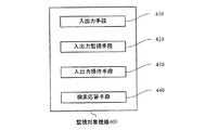
図4は、監視対象機器400の構成を示すブロック図である。監視対象機器400は、センサやアクチュエータなどの入出力手段410と、監視装置300からの要求に基づいて入出力手段410の状態を監視する入出力監視手段420と、監視装置300からの要求に基づいて入出力手段410に対する操作を行う入出力操作手段430と、監視装置300からの要求に基づいて自らのアクセス情報を通知する検索応答手段440とを備える。
FIG. 4 is a block diagram illustrating a configuration of the
なお、本発明においてアクセス情報とは、監視対象機器400を監視・操作するために必要な情報をいい、監視対象機器400の装置名称、ID、装置の種類などのデバイス情報や、監視対象機器400が備える監視・操作コマンドのことをいう。
In the present invention, access information refers to information necessary for monitoring and operating the
本発明において監視装置300とは、1または複数の監視対象機器400を監視および操作する機能を備えた装置をいう。監視対象機器400としては、例えば、空気調和機室内機や室外機を適用することができ、この場合、監視装置300としては空調設備コントローラを適用することができる。また、そのほか、監視対象機器400としては、照明設備を適用することができ、この場合、監視装置300としては照明設備管理コントローラを適用することができる。
In the present invention, the
図5は、本発明の実施の形態1に係る端末100、ルータ200、監視装置300、監視対象機器400の動作フローである。
監視装置300は、接続された監視対象機器400の検索を定期的に行う(S201)。検索が行われると、監視対象機器400は、自らのアクセス情報を監視装置300に通知する(S202)。検索は定期的に行い、監視装置300は監視対象機器400の最新の情報を定期的に得ることができる。なお、検索の頻度については、LAN600の規模等を考慮して適宜定める。
FIG. 5 is an operation flow of the
The
監視装置300は、ルータ200に対してポートマップ設定要求を送信する(S203)。ポートマップとは、ルータ200がWAN回線側のポートからLAN600側のポートにパケットを転送するための情報であり、WAN回線側のIPアドレスおよびポート番号と、これに対応するLAN600側のIPアドレスとを対にした情報である。監視装置300がポートマップを設定するにはUPnPプロトコルに従う必要があり、コントロールポイント機能330を使ってルータ200に対して設定要求を送信する。ルータ200は、ポートマップ設定要求に対する応答を返信する(S204)。そして、監視装置300はルータ200に保持されたポートマップ情報の取得要求を行い(S205)、ルータ200は応答を返信する(S206)。
The
監視装置300は、ステップS206で取得したポートマップ情報と、ステップS202で取得した監視対象機器400のアクセス情報とに基づいて、アクセス用URL一覧を含むWebコンテンツ350を生成する(S207)。アクセス用URL一覧は、監視装置300または監視対象機器400にアクセスするためのURL情報である。より具体的には、監視装置300または監視対象機器400の静的情報を取得するためのURLや、監視対象機器400に対して監視・操作コマンドを発行するためのURLを含む。アクセス用URL一覧は、Webブラウザで表示可能なスクリプト言語またはプログラム言語により記述されており、文字、図、写真、アイコン等を用いてユーザに分かりやすい形態で表現されている。ここで図6に、Webコンテンツ350の一例としてWeb画面351を示す。図6のWeb画面351においては、監視装置300の情報と、これに接続されている監視対象機器400の情報とHTML言語を用いて一覧表示し、一覧の中から選択した項目の情報を取得したり、監視・操作を行ったりできるようになっている。なお、図6では、Web画面351を文字のみで表現した場合の例について説明しているが、前述の通り、図、写真、アイコン等を用いて表現してもよい。
そして、監視装置300は、生成したWebコンテンツ350を、Webサーバ360に格納する(S208)。
Based on the port map information acquired in step S206 and the access information of the
The
監視装置300は、アクセス用URL一覧を含むWebコンテンツ350をルータ200を介して端末100に通知する(S209)。通知の手段は、ルータ200を経由する通信手段であればよく、例えば、電子メールを用いることができる。
The
端末100はアクセス用URL一覧を含むWebコンテンツ350を受信してWebブラウザ110に表示し、端末100側のユーザはアクセスしたい監視装置300または監視対象機器400を選択することができる(S210)。URLを選択すると、選択したURLの情報を含むパケットが端末100からルータ200へ送信され(S211)、ルータ200はポートマップ情報に基づいてポート転送を行う(S212)ので、端末100は監視装置300のWebサーバ360へアクセスすることができる。
The terminal 100 receives the
端末100からのアクセスが、Webコンテンツ350の静的情報の取得要求である場合には、Webサーバ360は、対応する応答をルータ200経由で送信する(S215)。また、端末100からのアクセスが、監視対象機器400に対する監視・操作コマンド発行要求である場合には、Webサーバ360は、監視・操作コマンド発行手段320を用いて監視対象機器400にコマンドを発行し(S213)、監視対象機器400からの応答(S214)をルータ200経由で送信する(S215)。
When the access from the terminal 100 is an acquisition request for static information of the
このように本実施の形態1によれば、監視装置300が監視装置アクセス用URL一覧を生成して端末100に通知し、端末100はこのアクセス用URL一覧を使って監視装置300または監視対象機器400にアクセスすることができるので、NAT越えを実現できる。したがって、端末100から容易にLAN600内の監視対象機器400にアクセスすることができる。
As described above, according to the first embodiment, the
実施の形態2.
図7は、本発明の実施の形態2に係るネットワークシステムのシステム構成の一例であり、複数の監視装置300を備える点が、前述の実施の形態1と異なる。図7のネットワークシステムにおいては、端末100と、UPnPに対応したルータ200と、UPnPのコントロールポイント機能を備えた監視装置300と、1または複数の監視対象機器400と、WAN回線としてのインターネット500と、LAN600とを備える。なお、本実施の形態2では、LAN600に2つの監視装置300を接続した場合の例について説明するが、監視装置300の数はこれに限られるものではない。また、以下の説明において、複数の監視装置300のうちの1つをマスタ監視装置300a、その他をセカンダリ監視装置300bと称する。また、マスタ監視装置300aと接続されたものを監視対象機器400a、セカンダリ監視装置300bと接続されたものを監視対象機器400bと称する。端末100、監視装置300、監視対象機器400、LAN600の基本的な構成については前述の実施の形態1と同様である。
FIG. 7 is an example of a system configuration of a network system according to
図8は、本実施の形態2に係る端末100、ルータ200、マスタ監視装置300a、セカンダリ監視装置300b、監視対象機器400a、監視対象機器400bの動作フローである。なお、本実施の形態2は、前述の実施の形態1で示した図5のステップS207以降の動作については同じであるので、以下、相違点であるステップS201〜S206に相当する部分(後述のステップS301〜310)を中心に説明する。
FIG. 8 is an operation flow of the terminal 100, the
図8において、マスタ監視装置300aは、LAN600内の他の監視装置300の接続状況をブロードキャストを用いて検索する(S301)。言い換えると、LAN600内で最初にブロードキャストを送信した監視装置300が、マスタ監視装置300aとなる。
In FIG. 8, the
マスタ監視装置300aは、前述の実施の形態1と同様に、接続された監視対象機器400aの検索を定期的に行う(S302)。検索が行われると、監視対象機器400は、自らのアクセス情報をマスタ監視装置300aに通知する(S303)。検索は定期的に行い、マスタ監視装置300aは監視対象機器400aの最新の情報を定期的に得ることができる。なお、検索の頻度については、LAN600の規模等を考慮して適宜定める。
As in the first embodiment, the
セカンダリ監視装置300bは、LAN600に参入すると、マスタ監視装置300aと同様に他の監視装置300の接続状況をブロードキャストを用いて検索する(S304)。LAN600に先に参入していたマスタ監視装置300aは、このブロードキャストに対して応答を行う(S305)。
When the
セカンダリ監視装置300bは、マスタ監視装置300aと同様に接続された監視対象機器400bの検索を定期的に行い、監視対象機器400bはその応答を行う(S306、S307)。ステップS306とS307は前述のステップS302とS303と同様の処理を行う。
The
監視対象機器400bの情報を得たセカンダリ監視装置300bは、この情報をマスタ監視装置300aに通知する(S308)。セカンダリ監視装置300bが複数存在する場合には、ステップS304〜S308と同様の動作をそれぞれが行う。これにより、マスタ監視装置300aは、LAN600に接続されたすべてのセカンダリ監視装置300bから、監視対象機器400の情報を取得することができる。
The
マスタ監視装置300aは、ルータ200に対してポートマップ設定要求を送信し(S309)、ルータ200が応答を行う(S310)。マスタ監視装置300aは、マスタ監視装置300aおよびLAN600内に存在するすべてのセカンダリ監視装置300bのIPアドレスを基にポートマップ設定を統一的に行うので、セカンダリ監視装置300bはポートマップ設定を行う必要がない。したがって、LAN600におけるトラフィック抑制の効果を得ることができる。なお、マスタ監視装置300aが何らかの理由により通信不能やダウン状態となった場合には、残りの監視装置300の中で最初にブロードキャストを送信した監視装置300がマスタ監視装置300aとなる。
The
ステップS310以降の処理は、前述の実施の形態1のステップS205以降と同様の処理を行う。 The processes after step S310 are the same as those after step S205 in the first embodiment.
このように本実施の形態2によれば、LAN内に監視装置300が複数存在する場合であっても、前述の実施の形態1と同様に端末100からNAT越えをして監視装置300および監視対象機器400にアクセスすることができる。
また、複数の監視装置300のうちの1つをマスタ監視装置300aとして、このマスタ監視装置300aがLAN600内のすべてのセカンダリ監視装置300bから監視対象機器400のアクセス情報を取得するようにしたので、情報を一元管理することができる。また、マスタ監視装置300aがすべての監視装置300のポートマップ設定を行うようにしたので、LAN600内のトラフィックを抑制する効果を得ることができる。
As described above, according to the second embodiment, even when there are a plurality of
In addition, since one of the plurality of
実施の形態3.
図9は、本発明の実施の形態3に係るネットワークシステムのシステム構成の一例である。本実施の形態3は、前述の実施の形態1と共通する構成を有しているが、WAN回線として電話回線700を備えた点および、ルータ200を設けないでモデム800を備えた点が異なる。図9のネットワークシステムにおいては、端末100と、モデム800と、監視装置300と、1または複数の監視対象機器400と、WAN回線としての電話回線700と、LAN600とを備える。なお、端末100に接続されたモデムをモデム800a、監視装置300に接続されたモデムをモデム800bと称す。端末100、監視装置300、監視対象機器400、LAN600の基本的な構成については前述の実施の形態1と同様である。
FIG. 9 is an example of a system configuration of a network system according to
端末100は、モデム800aのダイアルアップ機能を用いてモデム800bの有するサーバ機能に対して接続を行う。接続後は、TCP/IPベースの通信が可能となる。この接続においては、モデム800aのダイアルアップサーバ機能から端末100に貸与されるIPアドレスは、LAN600と同一セグメント帯に属するため、監視装置300はモデム800bに対してポートマップ設定を行わない。
The terminal 100 connects to the server function of the
以上のような構成において、本実施の形態3に係るネットワークシステムの動作について説明する。なお、本実施の形態3に係る動作は、前述の実施の形態1で示した図5と共通部分を有するので、図5を参照して説明する。 With the above configuration, the operation of the network system according to the third embodiment will be described. The operation according to the third embodiment has a common part with FIG. 5 described in the first embodiment and will be described with reference to FIG.
本実施の形態3においては、端末100、監視装置300、監視対象機器400は、図5のステップS203〜S206に係る処理以外の処理を同様にして行う。すなわち、監視装置300は、LAN600に接続された監視対象機器400の検索を定期的に行い(S201)、監視対象機器400のアクセス情報を取得する(S202)。そして、監視対象機器400のアクセス情報に基づいて、アクセス用URL一覧を含むWebコンテンツ350を生成し(S207)、Webサーバ360に格納する(S208)。
そして監視装置300は、Webコンテンツ350に含まれるアクセス用URL一覧をモデム800b、800aを介して端末100に通知する(S209に相当)。端末100はアクセス用URL一覧を含むWebコンテンツ350を受信してWebブラウザ110に表示し、端末100側のユーザはアクセスしたい監視装置300または監視対象機器400を選択することができる(S210)。選択したURLの情報を含むパケットは端末100からモデム800a、800bへ送信され(S211に相当)、端末100は監視装置300のWebサーバ360へアクセスすることができる。以降の動作については前述の実施の形態1と同様である。
In the third embodiment, the terminal 100, the
The
このように本実施の形態3によれば、WAN回線として電話回線700を用いた場合であっても、前述の実施の形態1と同様に端末100からNAT越えをして監視装置300および監視対象機器400にアクセスすることができる。
また、WAN回線としてインターネット回線を利用することができず電話回線700のみを使用可能な通信環境にある場合であっても、端末100による遠隔監視システムを構築することができる。
As described above, according to the third embodiment, even when the
Further, even in a communication environment where only the
実施の形態4.
図10は、本発明の実施の形態4に係るネットワークシステムのシステム構成の一例である。本実施の形態4においては、前述の実施の形態1と共通する構成を有しているが、LAN600とインターネット500とをVPNルータ900を介して接続した点と、端末100とインターネット500とを中継するVPNルータ900を設けた点が異なる。図10のネットワークシステムにおいては、端末100と、VPN(Virtual Private Network)ルータ900と、監視装置300と、1または複数の監視対象機器400と、WAN回線としてのインターネット500と、LAN600とを備える。なお、端末100に接続されたVPNルータをVPNルータ900a、監視装置300に接続されたVPNルータをVPNルータ900bと称す。端末100、監視装置300、監視対象機器400、LAN600の基本的な構成については前述の実施の形態1と同様である。
Embodiment 4 FIG.
FIG. 10 is an example of a system configuration of a network system according to Embodiment 4 of the present invention. The fourth embodiment has the same configuration as that of the first embodiment described above, but relays the terminal 100 and the
図10に示すVPNルータ900を用いた接続では、端末100と監視装置300とは同一セグメント帯に属するため、監視装置300はVPNルータ900bに対してポートマップ設定を行わない。
In the connection using the VPN router 900 shown in FIG. 10, since the terminal 100 and the
以上のような構成において、端末100、監視装置300、監視対象機器400は、前述の実施の形態3と同様の動作を行う。すなわち、前述の実施の形態1で示した図5のステップS203〜S206に係る処理以外の処理を、前述の実施の形態3と同様にして行う。
In the configuration as described above, the terminal 100, the
このように本実施の形態4によれば、端末100と監視装置300とをVPNルータ900で中継して接続した場合であっても、前述の実施の形態1と同様に端末100からNAT越えをして監視装置300および監視対象機器400にアクセスすることができる。
また、VPNルータ900を使用することで、端末100と監視装置300とのインターネット接続を暗号化することができ、インターネット接続の盗聴や不正操作などへのセキュリティ対策を行うことができる。
As described above, according to the fourth embodiment, even when the terminal 100 and the
Further, by using the VPN router 900, the Internet connection between the terminal 100 and the
実施の形態5.
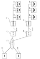
図11は、本発明の実施の形態5に係るネットワークシステムのシステム構成の一例である。本実施の形態5は、前述の実施の形態1と共通する構成を有しているが、インターネット500に複数のLAN600がルータ200を介して接続されている点が、異なる。図11のネットワークシステムにおいては、端末100と、ルータ200と、監視装置300と、1または複数の監視対象機器400と、WAN回線としてのインターネット500と、LAN600とを備える。インターネット500には、2つのルータ200が接続されており、その各々に対して、LAN600を介して監視装置300、監視対象機器400が接続されている。各構成要素の構成については前述の実施の形態1〜4で示したものと同様である。なお、本実施の形態5では、2つのLAN600がインターネット500に接続される場合の例について説明するが、接続されるLAN600の数はこれに限られるものではない。
Embodiment 5 FIG.
FIG. 11 is an example of a system configuration of a network system according to Embodiment 5 of the present invention. The fifth embodiment has the same configuration as that of the first embodiment described above, but is different in that a plurality of
以上のような構成においても、前述の実施の形態1と同様に、端末100からNAT越えをして監視装置300にアクセスすることができる。すなわち端末100は、インターネット500に分散して接続された複数の監視装置300または監視対象機器400にアクセスすることができる。したがって、離隔地にあるような複数の監視装置300や監視対象機器400に対しても、端末100からの遠隔監視操作を実現することができる。
Even in the configuration as described above, the
実施の形態6.
図12は、本発明の実施の形態6に係るネットワークシステムのシステム構成の一例である。本実施の形態6は、前述の実施の形態5と共通する構成を有しているが、インターネット500に接続された管理サーバ1000を設けた点が異なる。管理サーバ1000は、Webサーバ機能を有しており、後述するように監視装置300が生成したアクセス用URL一覧を集中管理して格納および送信する。その他の構成要素については、前述の実施の形態1〜5で示したものと同様である。
Embodiment 6 FIG.
FIG. 12 is an example of a system configuration of a network system according to Embodiment 6 of the present invention. The sixth embodiment has the same configuration as that of the fifth embodiment described above, but differs in that a
図13は、本実施の形態6に係る端末100、管理サーバ1000、ルータ200、監視装置300、監視対象機器400の動作フローである。本実施の形態6においては、前述の実施の形態1で示したステップS201からS208については同じ動作を行うので、相違点であるステップS401〜S409を中心に記載している。
FIG. 13 is an operation flow of the terminal 100, the
監視装置300は、アクセス用URL一覧を含むWebコンテンツ350を管理サーバ1000に対して送信する(S401)。インターネット500に複数の監視装置300がルータ200を介して接続されている場合には、各監視装置300が同様の動作を行う。
The
管理サーバ1000は、監視装置300から受信したアクセス用URL一覧を含むWebコンテンツ350をWebサーバへアップロードし、集中管理する(S402)。端末100は、インターネット500を介して管理サーバ1000にアクセスし、アクセス用URL一覧を取得する(S403)。そして、端末100側のユーザはアクセスしたい監視装置300または監視対象機器400をアクセス用URL一覧から選択する(S404)。選択したURLの情報を含むパケットは端末100からルータ200へ送信され(S405)、ルータ200はポートマップ情報に基づいてポート転送を行う(S406)ので、端末100は監視装置300のWebサーバ360へアクセスすることができる。
The
端末100からのアクセスが、Webコンテンツ350の静的情報の取得要求である場合には、Webサーバ360は、対応する情報をルータ200経由で応答を送信する(S409)。また、端末100からのアクセスが、監視対象機器400に対する監視・操作コマンド発行要求である場合には、Webサーバ360は、監視・操作コマンド発行手段320を用いて監視対象機器400にコマンドを発行し(S407)、監視対象機器400からの応答(S408)をルータ200経由で送信する(S409)。
When the access from the terminal 100 is an acquisition request for static information of the
このように本実施の形態6によれば、前述の実施の形態1と同様に、端末100からNAT越えをして監視装置300および監視対象機器400にアクセスすることができる。
また、端末100は、アクセス用URL一覧をインターネット500に接続された管理サーバを通じて取得することができるので、アクセス用URL一覧を受信するための特別の手段を設ける必要はない。このため、通信トラフィックを抑制することができる。
また、離隔地にある複数の監視装置300が有するアクセス用URL一覧を管理サーバ1000が集中管理するので、監視装置300の保守を容易に行うことができる。
As described above, according to the sixth embodiment, it is possible to access the
Further, since the terminal 100 can acquire the access URL list through the management server connected to the
In addition, since the
100 端末、200 ルータ、300 監視装置、400 監視対象機器、500 インターネット、600 LAN、700 電話回線、800 モデム、900 VPNルータ、1000 管理サーバ。 100 terminal, 200 router, 300 monitoring device, 400 monitored device, 500 Internet, 600 LAN, 700 telephone line, 800 modem, 900 VPN router, 1000 management server.
Claims (15)
前記監視対象機器にアクセスするためのアクセス情報を検出する監視対象機器検出手段と、
前記監視対象機器を監視操作するためのコマンドを発行する監視操作コマンド発行手段と、
前記監視対象機器にアクセスするためのアクセス用URL一覧を前記アクセス情報に基づいて生成するURL一覧生成手段と、
前記アクセス用URL一覧を格納および送信するWebサーバと、
前記アクセス用URL一覧を前記WANに接続された端末に対して前記中継器を介して通知するURL一覧通知手段とを備えた
ことを特徴とする監視装置。 A monitoring device connected to a LAN connected to a WAN via a repeater and monitoring a monitoring target device,
Monitoring target device detecting means for detecting access information for accessing the monitoring target device;
A monitoring operation command issuing means for issuing a command for monitoring the monitoring target device;
URL list generation means for generating an access URL list for accessing the monitored device based on the access information;
A web server for storing and transmitting the access URL list;
A monitoring apparatus comprising: a URL list notifying unit for notifying a terminal connected to the WAN of the access URL list via the repeater.
前記監視対象機器にアクセスするためのアクセス情報を検出する監視対象機器検出手段と、
前記監視対象機器を監視操作するためのコマンドを発行する監視操作コマンド発行手段と、
UPnPのコントロールポイントによる前記ルータへのアドレス変換テーブル設定手段と、
前記監視対象機器にアクセスするためのアクセス用URL一覧を前記アクセス情報に基づいて生成するURL一覧生成手段と、
前記アクセス用URL一覧を格納および送信するWebサーバと、
前記アクセス用URL一覧を前記WANに接続された端末に対して前記ルータを介して通知するURL一覧通知手段とを備えた
ことを特徴とする監視装置。 A monitoring device connected to a LAN connected to a WAN via a router and monitoring a monitoring target device,
Monitoring target device detecting means for detecting access information for accessing the monitoring target device;
A monitoring operation command issuing means for issuing a command for monitoring the monitoring target device;
An address translation table setting means for the router by a UPnP control point;
URL list generation means for generating an access URL list for accessing the monitored device based on the access information;
A web server for storing and transmitting the access URL list;
A monitoring apparatus comprising: a URL list notifying unit that notifies the terminal connected to the WAN of the access URL list via the router.
入出力手段と、
前記入出力手段の状態を監視する入出力監視手段と、
前記入出力手段の状態を変化させる入出力操作手段と、
前記監視装置からの要求に応じて自らのアクセス情報を送信する検索応答手段とを備えた
ことを特徴とする監視対象機器。 A monitoring target device monitored by a monitoring device connected to a LAN connected to a WAN via a router,
Input / output means;
Input / output monitoring means for monitoring the state of the input / output means;
Input / output operation means for changing the state of the input / output means;
A monitoring target device comprising: search response means for transmitting own access information in response to a request from the monitoring device.
前記WANに接続されたWebサーバ上のWebコンテンツを取得して表示するWebブラウザと、
前記Webサーバへアクセスするためのアクセス用URL一覧を受信するURL一覧受信手段とを備えた
ことを特徴とする端末。 A terminal connected to a WAN connected via a router and a LAN to which the monitoring target device and the monitoring device are connected;
A web browser that acquires and displays web content on a web server connected to the WAN;
A terminal comprising URL list receiving means for receiving an access URL list for accessing the Web server.
請求項3に記載の監視対象機器と、
請求項4に記載の端末とを備え、
前記端末は、前記監視装置のWebサーバに格納されたアクセス用URL一覧を用いて前記監視装置および監視対象機器にアクセスする
ことを特徴とするネットワークシステム。 The monitoring device according to claim 1 or 2,
The monitoring target device according to claim 3;
A terminal according to claim 4,
The network system, wherein the terminal accesses the monitoring device and the monitoring target device using an access URL list stored in a Web server of the monitoring device.
請求項3に記載の監視対象機器と、
請求項4に記載の端末とを備え、
前記複数の監視装置のうちの一の監視装置がマスタとなって他の監視装置のアドレス変換テーブル設定を代行し、
前記端末は、前記監視装置のWebサーバに格納されたアクセス用URL一覧を用いて前記監視装置および監視対象機器にアクセスする
ことを特徴とするネットワークシステム。 A plurality of monitoring devices according to claim 2;
The monitoring target device according to claim 3;
A terminal according to claim 4,
One monitoring device of the plurality of monitoring devices serves as a master to act as an address conversion table setting for other monitoring devices,
The network system, wherein the terminal accesses the monitoring device and the monitoring target device using an access URL list stored in a Web server of the monitoring device.
請求項3に記載の監視対象機器と、
請求項4に記載の端末とを備え、
前記監視装置と前記端末とはVPNによる通信を行い、
前記端末は、前記監視装置のWebサーバに格納されたアクセス用URL一覧を用いて前記監視装置および監視対象機器にアクセスする
ことを特徴とするネットワークシステム。 A monitoring device according to claim 2;
The monitoring target device according to claim 3;
A terminal according to claim 4,
The monitoring device and the terminal perform VPN communication,
The network system, wherein the terminal accesses the monitoring device and the monitoring target device using an access URL list stored in a Web server of the monitoring device.
請求項3に記載の監視対象機器と、
請求項4に記載の端末とを備え、
前記監視装置が接続された複数のLANがWANと接続されており、
前記端末は、前記監視装置のWebサーバに格納されたアクセス用URL一覧を用いて前記複数のLANに接続された前記監視装置および監視対象機器にアクセスする
ことを特徴とするネットワークシステム。 A monitoring device according to claim 2;
The monitoring target device according to claim 3;
A terminal according to claim 4,
A plurality of LANs connected to the monitoring device are connected to the WAN;
The network system, wherein the terminal accesses the monitoring device and monitoring target devices connected to the plurality of LANs using an access URL list stored in a Web server of the monitoring device.
前記複数のLANにそれぞれ接続され、監視対象機器にアクセスするためのアクセス用URL一覧を有する監視装置と、
前記WANに接続され、前記複数の監視装置から通知されるアクセス用URL一覧を格納および送信する管理サーバと、
前記WANに接続された端末とを有し、
前記端末は、前記管理サーバ上に格納されたアクセス用URL一覧を取得して表示するWebブラウザを備えており、これを用いて前記管理サーバを経由して前記監視対象機器へアクセスする
ことを特徴とするネットワークシステム。 In a network system composed of a plurality of LANs connected to a WAN via a repeater,
A monitoring device connected to each of the plurality of LANs and having a list of access URLs for accessing monitored devices;
A management server connected to the WAN and storing and transmitting an access URL list notified from the plurality of monitoring devices;
A terminal connected to the WAN,
The terminal includes a Web browser that acquires and displays a list of access URLs stored on the management server, and uses this to access the monitoring target device via the management server. Network system.
前記監視対象機器にアクセスするためのアクセス情報を検出する監視対象機器検出手段と、
前記監視対象機器を監視操作するためのコマンドを発行する監視操作コマンド発行手段と、
前記アクセス情報に基づいて前記監視対象機器へアクセスするためのアクセス用URL一覧を生成するURL一覧生成手段と、
前記アクセス用URL一覧を格納および送信するWebサーバと、
前記アクセス用URL一覧を前記WANに接続された端末に対して前記モデムを介して通知するURL一覧通知手段とを備えた
ことを特徴とする監視装置。 A monitoring device connected to a LAN connected to a WAN via a modem and monitoring a monitoring target device,
Monitoring target device detecting means for detecting access information for accessing the monitoring target device;
A monitoring operation command issuing means for issuing a command for monitoring the monitoring target device;
URL list generation means for generating an access URL list for accessing the monitored device based on the access information;
A web server for storing and transmitting the access URL list;
A monitoring apparatus comprising: a URL list notifying unit for notifying a terminal connected to the WAN of the access URL list via the modem.
入出力手段と、
前記入出力手段の状態を監視する入出力監視手段と、
前記入出力手段の状態を変化させる入出力操作手段と、
前記監視装置からの要求に応じて自らのアクセス情報を送信する検索応答手段とを備えた
ことを特徴とする監視対象機器。 A monitoring target device monitored by a monitoring device connected to a LAN connected to the WAN via a modem,
Input / output means;
Input / output monitoring means for monitoring the state of the input / output means;
Input / output operation means for changing the state of the input / output means;
A monitoring target device comprising: search response means for transmitting own access information in response to a request from the monitoring device.
前記WANに接続されたWebサーバ上のWebコンテンツを取得して表示するWebブラウザと、
前記Webサーバへアクセスするためのアクセス用URL一覧を受信するURL一覧受信手段とを備えた
ことを特徴とする端末。 A terminal connected by a WAN connected via a modem and a LAN to which the monitoring target device and its monitoring device are connected;
A web browser that acquires and displays web content on a web server connected to the WAN;
A terminal comprising URL list receiving means for receiving an access URL list for accessing the Web server.
請求項11に記載の監視対象機器と、
請求項12に記載の端末とを備え、
前記WANは電話回線によって構成されており、
前記端末は、前記監視装置のWebサーバに格納されたアクセス用URL一覧を用いて前記監視装置および監視対象機器にアクセスする
ことを特徴とするネットワークシステム。 A monitoring device according to claim 10;
The monitoring target device according to claim 11;
A terminal according to claim 12,
The WAN is constituted by a telephone line,
The network system, wherein the terminal accesses the monitoring device and the monitoring target device using an access URL list stored in a Web server of the monitoring device.
前記LANに接続された監視対象機器にアクセスするためのアクセス情報と、
UPnPのコントロールポイントによって設定されたアドレス変換テーブルと、
前記アクセス情報及びアドレス変換テーブルとに対応する監視対象機器とを関連づけたアクセス用URL一覧を生成する
ことを特徴とするURL一覧生成手段。 In a network system having a LAN connected to a WAN via a repeater,
Access information for accessing a monitoring target device connected to the LAN;
An address translation table set by UPnP control points;
A URL list generation means for generating an access URL list in which a monitoring target device corresponding to the access information and the address conversion table is associated.
前記LANに接続された監視対象機器にアクセスするためのアクセス用URL一覧を、前記WANに接続された端末に対して通知する
ことを特徴とするURL一覧通知手段。 In a network system having a LAN connected to a WAN via a repeater,
URL list notifying means for notifying a terminal connected to the WAN of an access URL list for accessing a monitoring target device connected to the LAN.
Priority Applications (1)
| Application Number | Priority Date | Filing Date | Title |
|---|---|---|---|
| JP2008164799A JP4889688B2 (en) | 2008-06-24 | 2008-06-24 | Network system |
Applications Claiming Priority (1)
| Application Number | Priority Date | Filing Date | Title |
|---|---|---|---|
| JP2008164799A JP4889688B2 (en) | 2008-06-24 | 2008-06-24 | Network system |
Publications (2)
| Publication Number | Publication Date |
|---|---|
| JP2010009129A true JP2010009129A (en) | 2010-01-14 |
| JP4889688B2 JP4889688B2 (en) | 2012-03-07 |
Family
ID=41589582
Family Applications (1)
| Application Number | Title | Priority Date | Filing Date |
|---|---|---|---|
| JP2008164799A Expired - Fee Related JP4889688B2 (en) | 2008-06-24 | 2008-06-24 | Network system |
Country Status (1)
| Country | Link |
|---|---|
| JP (1) | JP4889688B2 (en) |
Cited By (1)
| Publication number | Priority date | Publication date | Assignee | Title |
|---|---|---|---|---|
| CN103370926A (en) * | 2011-02-18 | 2013-10-23 | 村田机械株式会社 | Relayed communication system |
Citations (3)
| Publication number | Priority date | Publication date | Assignee | Title |
|---|---|---|---|---|
| JP2004349895A (en) * | 2003-05-20 | 2004-12-09 | Nec Access Technica Ltd | Lan interconnection apparatus and its upnp device disclosing method |
| JP2005244408A (en) * | 2004-02-25 | 2005-09-08 | Fujitsu Ltd | Gateway apparatus connected to plurality of networks with different network segments, and program and method for transferring ip packet |
| WO2007043381A1 (en) * | 2005-10-04 | 2007-04-19 | Matsushita Electric Industrial Co., Ltd. | Network communication device, network communication method, and address management device |
-
2008
- 2008-06-24 JP JP2008164799A patent/JP4889688B2/en not_active Expired - Fee Related
Patent Citations (3)
| Publication number | Priority date | Publication date | Assignee | Title |
|---|---|---|---|---|
| JP2004349895A (en) * | 2003-05-20 | 2004-12-09 | Nec Access Technica Ltd | Lan interconnection apparatus and its upnp device disclosing method |
| JP2005244408A (en) * | 2004-02-25 | 2005-09-08 | Fujitsu Ltd | Gateway apparatus connected to plurality of networks with different network segments, and program and method for transferring ip packet |
| WO2007043381A1 (en) * | 2005-10-04 | 2007-04-19 | Matsushita Electric Industrial Co., Ltd. | Network communication device, network communication method, and address management device |
Cited By (2)
| Publication number | Priority date | Publication date | Assignee | Title |
|---|---|---|---|---|
| CN103370926A (en) * | 2011-02-18 | 2013-10-23 | 村田机械株式会社 | Relayed communication system |
| US9357012B2 (en) | 2011-02-18 | 2016-05-31 | Murata Machinery, Ltd. | Relay communication system |
Also Published As
| Publication number | Publication date |
|---|---|
| JP4889688B2 (en) | 2012-03-07 |
Similar Documents
| Publication | Publication Date | Title |
|---|---|---|
| US8250238B2 (en) | Network device, address change notification method, and address change notification program | |
| JP5494649B2 (en) | Relay device, relay method, and relay device control program | |
| US20090055524A1 (en) | Network system | |
| GB2504648A (en) | Relay communication system and access management apparatus | |
| JP2006352666A (en) | Network household electric appliance control system | |
| JP5478546B2 (en) | Access control system and access control method | |
| JP2006203731A (en) | Network repeating device, network connection information browsing system and network connection information notification method | |
| JP6393475B2 (en) | Communication adapter device, communication system, tunnel communication method, and program | |
| JP2010004344A (en) | Method, device, system, and program for conducting remote accessing | |
| JP4889688B2 (en) | Network system | |
| JP2010245681A (en) | Home gateway device and home network system | |
| JP2009146306A (en) | Server device, communication terminal device, access system, access method, and access program | |
| JP5045094B2 (en) | Anomaly detection system, anomaly detection server and anomaly detection server program | |
| JP4900576B2 (en) | Program, storage medium, and image processing method | |
| JP6317630B2 (en) | Tunnel connection device, tunnel termination device, connection control method, and program | |
| JP2006086940A (en) | Image distribution system | |
| JP6002642B2 (en) | Communication node, network system, and device control method | |
| JP3864824B2 (en) | Notification method of access destination to home server system | |
| JP5721184B2 (en) | Electronic device control system and electronic device control method | |
| KR101241736B1 (en) | Port forwarding configuration method, terminal device and system using the same | |
| JP2004021334A (en) | Remote equipment monitor control method, and system therefor | |
| JP4945793B2 (en) | Electronic device, name resolution method, and name resolution control program | |
| JP5385935B2 (en) | Access control system and access control method | |
| JP2014068086A (en) | Operator system, remote support method, and program for operator system | |
| JP4079175B2 (en) | Network system |
Legal Events
| Date | Code | Title | Description |
|---|---|---|---|
| A977 | Report on retrieval |
Free format text: JAPANESE INTERMEDIATE CODE: A971007 Effective date: 20110325 |
|
| A131 | Notification of reasons for refusal |
Free format text: JAPANESE INTERMEDIATE CODE: A131 Effective date: 20110329 |
|
| A521 | Request for written amendment filed |
Free format text: JAPANESE INTERMEDIATE CODE: A523 Effective date: 20110527 |
|
| A131 | Notification of reasons for refusal |
Free format text: JAPANESE INTERMEDIATE CODE: A131 Effective date: 20110705 |
|
| A521 | Request for written amendment filed |
Free format text: JAPANESE INTERMEDIATE CODE: A523 Effective date: 20110902 |
|
| TRDD | Decision of grant or rejection written | ||
| A01 | Written decision to grant a patent or to grant a registration (utility model) |
Free format text: JAPANESE INTERMEDIATE CODE: A01 Effective date: 20111115 |
|
| A01 | Written decision to grant a patent or to grant a registration (utility model) |
Free format text: JAPANESE INTERMEDIATE CODE: A01 |
|
| A61 | First payment of annual fees (during grant procedure) |
Free format text: JAPANESE INTERMEDIATE CODE: A61 Effective date: 20111213 |
|
| R150 | Certificate of patent or registration of utility model |
Ref document number: 4889688 Country of ref document: JP Free format text: JAPANESE INTERMEDIATE CODE: R150 |
|
| FPAY | Renewal fee payment (event date is renewal date of database) |
Free format text: PAYMENT UNTIL: 20141222 Year of fee payment: 3 |
|
| R250 | Receipt of annual fees |
Free format text: JAPANESE INTERMEDIATE CODE: R250 |
|
| R250 | Receipt of annual fees |
Free format text: JAPANESE INTERMEDIATE CODE: R250 |
|
| R250 | Receipt of annual fees |
Free format text: JAPANESE INTERMEDIATE CODE: R250 |
|
| R250 | Receipt of annual fees |
Free format text: JAPANESE INTERMEDIATE CODE: R250 |
|
| R250 | Receipt of annual fees |
Free format text: JAPANESE INTERMEDIATE CODE: R250 |
|
| R250 | Receipt of annual fees |
Free format text: JAPANESE INTERMEDIATE CODE: R250 |
|
| R250 | Receipt of annual fees |
Free format text: JAPANESE INTERMEDIATE CODE: R250 |
|
| LAPS | Cancellation because of no payment of annual fees |