JP2010004329A - Image processing apparatus, image processing method, and program - Google Patents
Image processing apparatus, image processing method, and program Download PDFInfo
- Publication number
- JP2010004329A JP2010004329A JP2008161581A JP2008161581A JP2010004329A JP 2010004329 A JP2010004329 A JP 2010004329A JP 2008161581 A JP2008161581 A JP 2008161581A JP 2008161581 A JP2008161581 A JP 2008161581A JP 2010004329 A JP2010004329 A JP 2010004329A
- Authority
- JP
- Japan
- Prior art keywords
- motion blur
- shutter speed
- motion
- image
- image data
- Prior art date
- Legal status (The legal status is an assumption and is not a legal conclusion. Google has not performed a legal analysis and makes no representation as to the accuracy of the status listed.)
- Granted
Links
- 238000012545 processing Methods 0.000 title claims abstract description 605
- 238000003672 processing method Methods 0.000 title claims description 14
- 230000033001 locomotion Effects 0.000 claims abstract description 815
- 238000012937 correction Methods 0.000 claims abstract description 213
- 238000003384 imaging method Methods 0.000 claims abstract description 158
- 238000000034 method Methods 0.000 claims description 237
- 239000013598 vector Substances 0.000 claims description 230
- 230000008569 process Effects 0.000 claims description 177
- 238000004364 calculation method Methods 0.000 claims description 93
- 230000009467 reduction Effects 0.000 claims description 58
- 238000004458 analytical method Methods 0.000 claims description 37
- 230000008859 change Effects 0.000 claims description 37
- 238000001914 filtration Methods 0.000 claims description 25
- 230000015556 catabolic process Effects 0.000 claims description 21
- 238000006731 degradation reaction Methods 0.000 claims description 21
- 239000000284 extract Substances 0.000 claims description 6
- 208000012661 Dyskinesia Diseases 0.000 abstract description 52
- 230000006866 deterioration Effects 0.000 abstract description 35
- 230000010485 coping Effects 0.000 abstract 1
- 230000008030 elimination Effects 0.000 abstract 1
- 238000003379 elimination reaction Methods 0.000 abstract 1
- 230000000875 corresponding effect Effects 0.000 description 39
- 230000006870 function Effects 0.000 description 38
- 238000001514 detection method Methods 0.000 description 27
- 238000010586 diagram Methods 0.000 description 21
- 238000009499 grossing Methods 0.000 description 17
- 230000015572 biosynthetic process Effects 0.000 description 14
- 238000003786 synthesis reaction Methods 0.000 description 14
- 230000002093 peripheral effect Effects 0.000 description 13
- 238000003860 storage Methods 0.000 description 13
- 238000012935 Averaging Methods 0.000 description 12
- 230000004438 eyesight Effects 0.000 description 11
- 238000011946 reduction process Methods 0.000 description 10
- 238000013459 approach Methods 0.000 description 9
- 230000008447 perception Effects 0.000 description 8
- 230000000007 visual effect Effects 0.000 description 8
- 238000009825 accumulation Methods 0.000 description 6
- 238000006243 chemical reaction Methods 0.000 description 5
- 238000010191 image analysis Methods 0.000 description 4
- 230000007423 decrease Effects 0.000 description 3
- 238000003708 edge detection Methods 0.000 description 3
- 230000006872 improvement Effects 0.000 description 3
- 239000004973 liquid crystal related substance Substances 0.000 description 3
- 238000013178 mathematical model Methods 0.000 description 3
- 239000000203 mixture Substances 0.000 description 3
- 230000003287 optical effect Effects 0.000 description 3
- 230000002194 synthesizing effect Effects 0.000 description 3
- 230000002123 temporal effect Effects 0.000 description 3
- 230000005540 biological transmission Effects 0.000 description 2
- 230000008094 contradictory effect Effects 0.000 description 2
- 230000001276 controlling effect Effects 0.000 description 2
- 230000002596 correlated effect Effects 0.000 description 2
- 230000001934 delay Effects 0.000 description 2
- 230000003111 delayed effect Effects 0.000 description 2
- 238000012217 deletion Methods 0.000 description 2
- 230000037430 deletion Effects 0.000 description 2
- 238000011156 evaluation Methods 0.000 description 2
- 238000002474 experimental method Methods 0.000 description 2
- 238000000605 extraction Methods 0.000 description 2
- 230000010365 information processing Effects 0.000 description 2
- 238000004519 manufacturing process Methods 0.000 description 2
- 238000002156 mixing Methods 0.000 description 2
- 230000000750 progressive effect Effects 0.000 description 2
- 230000035939 shock Effects 0.000 description 2
- 230000003044 adaptive effect Effects 0.000 description 1
- 230000003190 augmentative effect Effects 0.000 description 1
- 230000001413 cellular effect Effects 0.000 description 1
- 238000004891 communication Methods 0.000 description 1
- 238000010835 comparative analysis Methods 0.000 description 1
- 238000004590 computer program Methods 0.000 description 1
- 238000009792 diffusion process Methods 0.000 description 1
- 230000000694 effects Effects 0.000 description 1
- 238000005516 engineering process Methods 0.000 description 1
- 238000007429 general method Methods 0.000 description 1
- 230000007774 longterm Effects 0.000 description 1
- 230000007246 mechanism Effects 0.000 description 1
- 238000010187 selection method Methods 0.000 description 1
- 239000004065 semiconductor Substances 0.000 description 1
- 238000004088 simulation Methods 0.000 description 1
- 238000001228 spectrum Methods 0.000 description 1
- 238000012546 transfer Methods 0.000 description 1
- 230000007704 transition Effects 0.000 description 1
- 238000002834 transmittance Methods 0.000 description 1
- 230000016776 visual perception Effects 0.000 description 1
Images


Classifications
-
- G—PHYSICS
- G06—COMPUTING; CALCULATING OR COUNTING
- G06T—IMAGE DATA PROCESSING OR GENERATION, IN GENERAL
- G06T5/00—Image enhancement or restoration
- G06T5/70—Denoising; Smoothing
-
- G—PHYSICS
- G06—COMPUTING; CALCULATING OR COUNTING
- G06T—IMAGE DATA PROCESSING OR GENERATION, IN GENERAL
- G06T5/00—Image enhancement or restoration
- G06T5/73—Deblurring; Sharpening
-
- H—ELECTRICITY
- H04—ELECTRIC COMMUNICATION TECHNIQUE
- H04N—PICTORIAL COMMUNICATION, e.g. TELEVISION
- H04N23/00—Cameras or camera modules comprising electronic image sensors; Control thereof
- H04N23/70—Circuitry for compensating brightness variation in the scene
-
- H—ELECTRICITY
- H04—ELECTRIC COMMUNICATION TECHNIQUE
- H04N—PICTORIAL COMMUNICATION, e.g. TELEVISION
- H04N23/00—Cameras or camera modules comprising electronic image sensors; Control thereof
- H04N23/70—Circuitry for compensating brightness variation in the scene
- H04N23/76—Circuitry for compensating brightness variation in the scene by influencing the image signals
-
- G—PHYSICS
- G06—COMPUTING; CALCULATING OR COUNTING
- G06T—IMAGE DATA PROCESSING OR GENERATION, IN GENERAL
- G06T2207/00—Indexing scheme for image analysis or image enhancement
- G06T2207/20—Special algorithmic details
- G06T2207/20172—Image enhancement details
- G06T2207/20201—Motion blur correction
-
- H—ELECTRICITY
- H04—ELECTRIC COMMUNICATION TECHNIQUE
- H04N—PICTORIAL COMMUNICATION, e.g. TELEVISION
- H04N5/00—Details of television systems
- H04N5/14—Picture signal circuitry for video frequency region
- H04N5/144—Movement detection
- H04N5/145—Movement estimation
Landscapes
- Engineering & Computer Science (AREA)
- Multimedia (AREA)
- Signal Processing (AREA)
- Physics & Mathematics (AREA)
- General Physics & Mathematics (AREA)
- Theoretical Computer Science (AREA)
- Studio Devices (AREA)
- Picture Signal Circuits (AREA)
- Adjustment Of Camera Lenses (AREA)
Abstract
Description
本発明は画像処理装置、画像処理方法、プログラムに関し、特に画像上の動きぼけの観点に注目し、高品質な画像を得るようにするための画像処理技術に関する。 The present invention relates to an image processing apparatus, an image processing method, and a program, and particularly to an image processing technique for obtaining a high-quality image by paying attention to the viewpoint of motion blur on an image.
高速シャッタで撮像された動画像やアニメーションなどを、プロジェクタやディスプレイなどの表示デバイスを用いて表示すると、画像中に含まれる移動物体の動きが不連続に表示され、画像を観察する観察者が多重像を知覚してしまうという画像劣化が頻繁に発生する。このような動きの不自然さによる動画像の劣化は、一般的にモーションジャーキネス(Motion Jerkiness)と呼ばれる。
一方、オープンシャッタなど低速のシャッタスピードで撮像された動画像を表示すると、動きぼけの影響により、被写体のディテールの欠損やエッジが不鮮明になることがよくある。この現象は、ブラー(動きぼけ)と呼ばれる画質劣化の現象である。
When moving images or animations captured with a high-speed shutter are displayed using a display device such as a projector or display, the movement of moving objects contained in the images is displayed discontinuously, and multiple observers observe the images. Deterioration of the image frequently occurs such that the image is perceived. Such degradation of a moving image due to unnaturalness of motion is generally called motion jerkiness.
On the other hand, when a moving image captured at a low shutter speed, such as an open shutter, is displayed, the loss of details and edges of the subject often become blurred due to the influence of motion blur. This phenomenon is a phenomenon of image quality deterioration called blur (motion blur).
これらのジャーキネスとブラーの発生原理について、図26〜図28を用いて説明する。人間の知覚特性として、目に入射した光を一定時間積分した値として知覚することが知られている。図26〜図28は、この知覚特性に基づく観察者からの物体の見え方を模擬的に説明する図である。 The generation principle of these jerkiness and blur will be described with reference to FIGS. As a human perceptual characteristic, it is known to perceive light incident on the eye as a value obtained by integrating for a certain period of time. FIG. 26 to FIG. 28 are diagrams for simulating the appearance of an object from the observer based on this perceptual characteristic.
図26は、静止物体と移動物体の実世界における見え方を説明する例である。
図26(1)は、横軸を位置(x)、縦軸を時間(t)として、静止物体71と移動物体72の時間的変移を示しており、図26(2)は、これらの静止物体71と移動物体72を観察する観察者の知覚状況を模擬的に示した図である。観察者には、移動物体72を追従して観察する追従視と、および移動物体72を追従しないで視点を固定して観察する固定視を行なう2通りの異なる観察形態における知覚状況がある。それぞれ(a)追従視,(b)固定視として示してある。
FIG. 26 is an example for explaining how a stationary object and a moving object appear in the real world.
FIG. 26 (1) shows the temporal transition of the
図26(2)の(a)追従視に示すように、移動物体72を観察者が追従視した場合、移動物体72の見え方は、図26(2)の移動物体知覚情報a72のようになる。これは図26(2)の(b)固定視における固定物体71の見え方である固定物体知覚情報b71と同様の見え方である。このように、観察者が移動物体72を追従視した場合は、固定視における固定物体71の見え方と同様に観察者は知覚する。
一方、図26(2)の(b)固定視に示すように、移動物体72を観察者が固定視した場合、移動物体72の見え方は、図26(2)の移動物体知覚情報b72のようになる。これは、観察者が移動物体を連続的に移動するように変化する知覚を行うものであり、観察者が違和感を生じることはない。
As shown in (a) following vision in FIG. 26 (2), when the observer follows the moving object 72, the appearance of the moving object 72 is as the moving object perception information a72 in FIG. 26 (2). Become. This is the same appearance as the fixed object perception information b71 which is the appearance of the
On the other hand, as shown in (b) fixed vision in FIG. 26 (2), when the observer views the moving object 72 in a fixed manner, the moving object 72 is viewed in the moving object perception information b72 in FIG. 26 (2). It becomes like this. This is a perception that the observer changes so as to continuously move the moving object, and the observer does not feel uncomfortable.
図27は、高速シャッタで撮像された動画像やアニメーションなどを、プロジェクタやディスプレイなどの表示デバイスを用いて表示した場合に観察者によって知覚されるジャーキネスの発生を説明する図である。すなわち、画像中に含まれる移動物体の動きが不連続に表示され、画像を観察する観察者が多重像を知覚してしまうという現象である。 FIG. 27 is a diagram for explaining the occurrence of jerkiness perceived by an observer when a moving image or animation captured with a high-speed shutter is displayed using a display device such as a projector or a display. That is, this is a phenomenon in which the movement of a moving object included in an image is displayed discontinuously, and an observer who observes the image perceives multiple images.
図27では、図26中の実世界における移動物体を、高速シャッタを用いて撮像し、60Hzでリフレッシュされる表示デバイスに表示した場合、観察者からの見え方を模擬的に表している。図27(1)は、表示静止物体81と表示移動物体82の表示デバイス上での表示位置の変化を示している。縦軸が時間(t)であり表示デバイスのリフレッシュ間隔(1/60sec)毎に区切りを設定してある。横軸が表示位置(x)である。
図27(2)は、表示デバイスに表示される表示静止物体81と表示移動物体82を観察する観察者の知覚状況を模擬的に示した図である。観察者の知覚状況として、表示移動物体82を追従して観察する追従視を、(a)追従視として示し、表示移動物体82を追従しないで視点を固定して観察する固定視を、(b)固定視として示している。
In FIG. 27, when the moving object in the real world in FIG. 26 is imaged using a high-speed shutter and displayed on a display device refreshed at 60 Hz, the appearance from the observer is simulated. FIG. 27A shows changes in the display position of the display stationary object 81 and the display moving object 82 on the display device. The vertical axis represents time (t), and a break is set for each refresh interval (1/60 sec) of the display device. The horizontal axis is the display position (x).
FIG. 27B is a diagram schematically illustrating the perception state of an observer observing the display stationary object 81 and the display moving object 82 displayed on the display device. As the observer's perception status, the following vision for observing the display moving object 82 is shown as (a) following vision, and the fixed vision for observing with the viewpoint fixed without following the display moving object 82 (b) ) Shown as fixed vision.
図27(2)(a)に示すように、表示デバイスに表示される表示移動物体82を、観察者が追従視した場合の見え方(a82)は、上記図26(2)(a)の追従視の見え方(a82)と同様の見え方であり、静止物体を固定視した場合と同じように観察者は知覚することになる。 As shown in FIGS. 27 (2) (a), the appearance (a82) when the observer follows the display moving object 82 displayed on the display device is as shown in FIG. 26 (2) (a). It looks like the way of following vision (a82), and the observer perceives it in the same way as when a stationary object is fixed.
一方、表示デバイスに表示される表示移動物体82を、観察者が固定視した場合においては、図27(2)(b)に示すように、観察者の視覚による知覚上、実世界とは異なり表示移動物体82は、連続的ではなく離散的に移動変化するような見え方(b22)となる。結果として、観測者は、目に入射した光を一定時間積分した値として知覚するという知覚特性に基づいて、表示デバイスに表示される移動物体を多重像として知覚することになる。 On the other hand, when the observer moves the display moving object 82 displayed on the display device, as shown in FIGS. 27 (2) and 27 (b), it differs from the real world in terms of visual perception by the observer. The display moving object 82 looks (b22) so as to move and change discretely instead of continuously. As a result, the observer perceives the moving object displayed on the display device as a multiple image based on the perceptual characteristic of perceiving the light incident on the eye as a value integrated for a certain time.
観測者は、本来1つの物体であるにも拘らず、複数の物体のように感じ取ってしまうことになる。このような現象をジャーキネス劣化という。ジャーキネス劣化は、原理的に移動速度の速い物体ほど発生しやすい。また、ジャーキネス劣化は、表示デバイスのフレームレートが低いほど発生しやすく、フレームレートが高いほど発生しにくい。さらに、ジャーキネス劣化は、一般的に、空間的な輝度の変化が大きい部分、言い換えれば、空間コントラストの高い部分において生じやすい。 Even though the observer is originally a single object, the observer feels like a plurality of objects. Such a phenomenon is called jerkiness degradation. In principle, jerkiness degradation is more likely to occur in an object having a higher moving speed. Further, jerkiness deterioration is more likely to occur as the frame rate of the display device is lower, and is less likely to occur as the frame rate is higher. Further, jerkiness degradation generally tends to occur in a portion where the spatial luminance change is large, in other words, in a portion where the spatial contrast is high.
図28は、例えばオープンシャッタなどの低速シャッタで撮像された動画像やアニメーションなどを、プロジェクタやディスプレイなどの表示デバイスを用いて表示した場合に観察者によって知覚されるブラーの発生を説明する図である。ブラーは、動きボケの影響により、被写体のディテールの欠損やエッジが不鮮明になる現象である。 FIG. 28 is a diagram for explaining the occurrence of blur perceived by an observer when a moving image or animation captured by a low-speed shutter such as an open shutter is displayed using a display device such as a projector or a display. is there. Blur is a phenomenon in which the details of an object are lost or the edges are unclear due to motion blur.
図28では、図26中の実世界における移動物体を、低速シャッタを用いて撮像し、60Hzでリフレッシュされる表示デバイスに表示した場合、観察者からの見え方を模擬的に表している。図28(1)は、表示静止物体91と表示移動物体92の表示デバイス上での表示位置の変化を示している。縦軸が時間(t)であり表示デバイスのリフレッシュ間隔(1/60sec)毎に区切りを設定してある。横軸が表示位置(x)である。
図28(2)は、表示デバイスに表示される表示静止物体91と表示移動物体92を観察する観察者の知覚状況を模擬的に示している。即ち表示移動物体32を追従して観察する(a)追従視と、表示移動物体32を追従しないで視点を固定して観察する(b)固定視を示している。
In FIG. 28, when the moving object in the real world in FIG. 26 is imaged using a low-speed shutter and displayed on a display device refreshed at 60 Hz, the appearance from the observer is simulated. FIG. 28 (1) shows changes in the display position of the display stationary object 91 and the display moving object 92 on the display device. The vertical axis represents time (t), and a break is set for each refresh interval (1/60 sec) of the display device. The horizontal axis is the display position (x).
FIG. 28 (2) schematically shows the perception state of an observer who observes the display stationary object 91 and the display moving object 92 displayed on the display device. That is, (a) follow-up observation in which the
図28(2)(b)に示すように、表示デバイスに表示される表示移動物体32を、観察者が固定視した場合(b32)においては、上記図26(2)(b)の固定視と同様の見え方(b72)であり、観察者が移動物体を連続的に移動するように変化する知覚を行い、観察者が違和感を生じることはない。
As shown in FIGS. 28 (2) and 28 (b), when the observer fixedly views the
一方、表示デバイスに表示される表示移動物体92を、観察者が追従視した場合においては、図28(2)(a)の見え方(a92)に示すように、観察者には、静止物体を固定視した場合とは異なる、ぼやけた像として知覚される。これは、図28(1)の表示移動物体92に示すように、撮像時において、低速シャッタに基づく長期間の露光中の移動物体の動きが1フレームに記録され、この移動する物体が1フレーム中に帯状に表示されるためである。このような現象をブラー劣化という。 On the other hand, when the observer follows the display moving object 92 displayed on the display device, as shown in the view (a92) in FIGS. The image is perceived as a blurred image, which is different from when the image is fixed. This is because, as shown by the display moving object 92 in FIG. 28 (1), the movement of the moving object during long-term exposure based on the low-speed shutter is recorded in one frame at the time of imaging. This is because it is displayed in a strip shape. Such a phenomenon is called blurring deterioration.
ジャーキネス劣化およびブラー劣化の発生は、原理的に見て、撮像時のシャッタ速度について相反する関係にあるため、単純なシャッタ制御ではいずれかの劣化が目立ってしまう。
具体的には、動画像のフレームレートに対して短いシャッタ速度(高速シャッタ)で撮像された画像は、静止画像として表示したときには鮮鋭度が高いが、動画像として表示したときには、画像中の動体領域、特に高速に動く領域の動きが滑らかではなく、人間の視覚特性上、不自然に見えてしまう。
それに対し、動画像のフレームレートに対して長いシャッタ速度(低速シャッタ)で撮像された画像を動画像として表示したときには、画像中の高速移動領域の動きは滑らかであるが、画像全体の鮮鋭度は低減してしまう。
Since the occurrence of jerkiness and blurring is in principle a contradictory relationship with respect to the shutter speed at the time of imaging, any deterioration is conspicuous with simple shutter control.
Specifically, an image captured at a shutter speed (high shutter speed) that is shorter than the frame rate of the moving image has high sharpness when displayed as a still image, but when displayed as a moving image, a moving object in the image The movement of the area, particularly the area moving at high speed, is not smooth, and looks unnatural due to human visual characteristics.
On the other hand, when an image captured at a shutter speed (low shutter speed) that is longer than the frame rate of the moving image is displayed as a moving image, the movement of the high-speed moving area in the image is smooth, but the sharpness of the entire image Will be reduced.
本出願人が先に提案した発明として、上記特許文献1に示されるように、高速シャッタで撮像された画像の入力を主に想定し、画像処理を用いて動きぼけを付加することで、ジャーキネスの発生を低減する方法が知られている。
また、その際に動きぼけの過付加によるブラー劣化が発生しないよう、画像処理手法を用いた解析により動きぼけ付加量を制御することも示している。
また、主に低速シャッタで撮像された画像の入力を想定し、画像処理を用いて動きぼけを削減するアプローチは、一般に広く検討されているテーマである。例えば、上記非特許文献1,2によれば、画像のぼけを補正する画像処理手法として、ぼけモデルを用いた逆たたみ込み法と、ピーキング法やショックフィルタ(Shock Filter)に代表されるぼけモデルが不要な手法とに大別され、非特許文献1では前者に所属する手法を動きぼけの削減手段として適用し、非特許文献2では後者に所属する手法を動きぼけの削減手段として適用している。
As the invention previously proposed by the present applicant, as shown in the above-mentioned
It also shows that the motion blur addition amount is controlled by analysis using an image processing method so that blur deterioration due to excessive motion blur addition does not occur at that time.
In addition, an approach for reducing motion blur using image processing assuming an input of an image captured mainly by a low-speed shutter is a widely studied theme. For example, according to
上述のように、ジャーキネスおよびブラーの発生は、撮像時のシャッタ速度について、相反する関係にあるため、単純なシャッタ制御ではいずれかの劣化が目立ってしまう問題がある。
そしてジャーキネスおよびブラーの劣化に適切に対応して画質向上を図る技術は提案されておらず、そこで本発明では、動画質劣化の要因であるこれらの劣化に適切に対応すること、さらにはジャーキネスとブラーの双方を抑制するよう、ジャーキネス及びブラーに適応的に対応した画像処理を行う技術を提供することを目的とする。
As described above, the occurrence of jerkiness and blur has a contradictory relationship with respect to the shutter speed at the time of imaging, and thus there is a problem that any deterioration is conspicuous in simple shutter control.
No technology has been proposed for improving the image quality by appropriately responding to the deterioration of jerkiness and blur. Therefore, in the present invention, it is necessary to appropriately cope with such deterioration, which is a factor of deterioration of moving image quality. An object of the present invention is to provide a technique for performing image processing adaptively corresponding to jerkiness and blur so as to suppress both blurs.
本発明の画像処理装置は、画像データを構成する単位画像間での画像の動きを示す動き情報、及び上記画像データを撮像した時のシャッタ速度情報を基に、動きぼけ補正処理に必要な動きぼけ補正パラメータを算出する補正パラメータ算出手段と、上記動きぼけ補正パラメータを用いて、少なくとも動きぼけを削減する処理を実行し、画像データに含まれる動きぼけ量を補正する動きぼけ補正処理手段とを備える。
また上記動きぼけ補正処理手段は、上記動きぼけ補正パラメータを用いて、画像データに動きぼけを付加する処理及び動きぼけを削減する処理を実行する。
また上記画像データを解析処理することで上記シャッタ速度情報を推定するシャッタ速度推定処理手段をさらに備え、上記補正パラメータ算出手段は、補正パラメータの算出の際に、上記シャッタ速度推定処理手段で推定されたシャッタ速度情報を用いる。
The image processing apparatus according to the present invention provides motion necessary for motion blur correction processing based on motion information indicating image motion between unit images constituting image data, and shutter speed information when the image data is captured. Correction parameter calculation means for calculating a blur correction parameter, and motion blur correction processing means for executing at least a process for reducing motion blur using the motion blur correction parameter and correcting a motion blur amount included in image data. Prepare.
The motion blur correction processing means executes processing for adding motion blur to the image data and processing for reducing motion blur using the motion blur correction parameter.
The image processing apparatus further includes shutter speed estimation processing means for estimating the shutter speed information by analyzing the image data, and the correction parameter calculation means is estimated by the shutter speed estimation processing means when calculating the correction parameter. Shutter speed information is used.
また上記動きぼけ補正処理手段は、上記動きぼけ補正パラメータを基に、画像データに動きぼけを付加する処理又は動きぼけを削減する処理を、画像データ内の分割領域ごとに適応的に選択し、選択した動きぼけ補正処理を実行する。
或いは、上記動きぼけ補正処理手段は、画像データに対し、動きぼけを付加する処理及び動きぼけを削減する処理をそれぞれ独立に実行し、処理された双方の画像データから、上記動きぼけ補正パラメータを基に、画像データ内の分割領域ごとに適応的に出力するデータを選択して出力する。
The motion blur correction processing means adaptively selects, for each divided region in the image data, a process for adding motion blur to the image data or a process for reducing motion blur based on the motion blur correction parameter. The selected motion blur correction process is executed.
Alternatively, the motion blur correction processing unit independently executes a process for adding motion blur and a process for reducing motion blur to the image data, and sets the motion blur correction parameter from both processed image data. Based on this, data to be adaptively output is selected and output for each divided region in the image data.
また上記画像データから、上記動き情報として動きベクトルを生成する動きベクトル生成手段を更に備え、上記動きぼけ補正手段は、上記動きベクトル生成手段により生成された動きベクトルを用いて、上記画像データにフィルタ処理を施すことにより、動きぼけの補正処理を実行する。 The image data further includes motion vector generation means for generating a motion vector as the motion information, and the motion blur correction means filters the image data using the motion vector generated by the motion vector generation means. By performing the process, a motion blur correction process is executed.
また上記シャッタ速度推定処理手段は、画像データ中の対象領域に含まれる動きぼけの特性を解析し、シャッタ速度演算用パラメータを抽出する動きぼけ特性解析部と、上記動きぼけ特性解析手段により抽出されたシャッタ速度演算用パラメータ、及び上記対象領域に対応する動き情報を用いて、上記画像データを撮像した時のシャッタ速度情報を算出する撮像シャッタ速度演算部とを備える。
またこの場合、上記シャッタ速度推定処理手段は、上記動きぼけ特性解析手段による解析処理の対象領域を、上記画像データを構成する各単位画像中から抽出して特定する処理対象領域選択部をさらに備える。
また上記画像データから、上記動き情報として動きベクトルを生成する動きベクトル生成手段を更に備え、上記シャッタ速度推定処理手段における上記処理対象領域選択部は、上記画像データのエッジ情報、及び上記動きベクトル生成手段で生成された動きベクトルの情報を用いて、上記対象領域を特定する。
また上記シャッタ速度推定処理手段は、撮像シャッタ速度高精度化処理部を更に備え、上記シャッタ速度推定処理手段においては、上記動きぼけ特性解析部は、複数の対象領域について上記シャッタ速度演算用パラメータを抽出し、上記撮像シャッタ速度演算部は、複数の対象領域について上記シャッタ速度演算用パラメータとそれぞれの対象領域に対応する動き情報を用いて、複数の上記シャッタ速度情報を算出し、上記撮像シャッタ速度高精度化処理部は、複数の上記シャッタ速度情報の算出結果を用いて、撮像シャッタ速度の推定を行う。
The shutter speed estimation processing means analyzes the motion blur characteristics included in the target area in the image data, and extracts the shutter speed calculation parameters, and the motion blur characteristics analysis means extracts the motion blur characteristics analysis means. And an imaging shutter speed calculation unit that calculates shutter speed information when the image data is captured using the shutter speed calculation parameter and the motion information corresponding to the target area.
In this case, the shutter speed estimation processing unit further includes a processing target region selection unit that extracts and specifies a target region for analysis processing by the motion blur characteristic analysis unit from each unit image constituting the image data. .
The image processing apparatus further includes a motion vector generation unit that generates a motion vector as the motion information from the image data, and the processing target region selection unit in the shutter speed estimation processing unit includes edge information of the image data and the motion vector generation The target area is specified using information on the motion vector generated by the means.
The shutter speed estimation processing means further includes an imaging shutter speed high accuracy processing section. In the shutter speed estimation processing means, the motion blur characteristic analysis section sets the shutter speed calculation parameters for a plurality of target areas. The imaging shutter speed calculation unit calculates a plurality of the shutter speed information using the shutter speed calculation parameter and motion information corresponding to each target area for the plurality of target areas, and extracts the imaging shutter speed. The high accuracy processing unit estimates the imaging shutter speed using the calculation results of the plurality of shutter speed information.
また上記シャッタ速度推定処理手段は、入力される画像データについてのシーンチェンジが検出されてから次のシーンチェンジが検出されるまでの期間に、1回のみシャッタ速度推定処理を行うとともに、当該期間中は、上記1回のシャッタ速度推定処理の結果を保持する。
或いは上記シャッタ速度推定処理手段は、入力される画像データについてのシーンチェンジが検出されてから次のシーンチェンジが検出されるまでの期間に、複数回のシャッタ速度推定処理を行うとともに、上記複数回のシャッタ速度推定処理による複数のシャッタ速度情報の算出結果を用いて、撮像シャッタ速度の推定を行う撮像シャッタ速度高精度化処理部をさらに備える。
なお、これらは撮像シャッタ速度の変更が、シーンチェンジの前後においてのみ発生する可能性を持つ、という仮定のもとにおいて有効である。
The shutter speed estimation processing means performs the shutter speed estimation process only once during a period from when a scene change is detected for input image data until the next scene change is detected. Holds the result of the one-time shutter speed estimation process.
Alternatively, the shutter speed estimation processing means performs the shutter speed estimation process a plurality of times during a period from when a scene change is detected with respect to input image data until the next scene change is detected, and the plurality of times. An imaging shutter speed enhancement processing unit that estimates the imaging shutter speed using the calculation result of the plurality of shutter speed information by the shutter speed estimation process is further provided.
Note that these are effective under the assumption that the change of the imaging shutter speed may occur only before and after the scene change.
また上記補正パラメータ算出手段は、被写体速度と、出力画像の画像劣化が低減される撮像シャッタ速度とを対応付ける対応付け情報を保持し、該対応付け情報を参照して、被写体速度に対応する最適シャッタ速度を画像データ内の分割領域毎に取得し、入力された撮像シャッタ速度の情報と上記最適シャッタ速度とを比較することで、動きぼけを付加する処理又は動きぼけを削減する処理の選択制御情報である動きぼけ補正パラメータを算出し、上記動きぼけ補正処理手段は、上記動きぼけ補正パラメータに基づいて、画像データに動きぼけを付加する処理及び動きぼけを削減する処理を選択的に実行する。
また上記補正パラメータ算出手段は、被写体速度と、出力画像の画像劣化が低減される撮像シャッタ速度とを対応付ける対応付け情報を保持し、該対応付け情報を参照して、被写体速度に対応する最適シャッタ速度を画像データ内の分割領域毎に取得し、入力された撮像シャッタ速度の情報と上記最適シャッタ速度とを比較することで、動きぼけを付加する処理又は動きぼけを削減する処理の選択制御情報である動きぼけ補正パラメータを算出し、上記動きぼけ補正処理手段は、画像データに対し、動きぼけを付加する処理及び動きぼけを削減する処理をそれぞれ独立に実行し、処理された双方の画像データから、上記動きぼけ補正パラメータを基に、画像データ内の分割領域ごとに適応的に出力するデータを選択して出力する。
また上記補正パラメータ算出手段は、上記動きぼけ補正処理手段において画像データに動きぼけを付加する処理又は動きぼけを削減する処理の実行の際の、付加又は削減の度合いを示す動きぼけ補正パラメータを算出する。
また上記付加又は削減の度合いを示す動きぼけ補正パラメータは、撮像シャッタ速度、又は撮像シャッタ速度と上記最適シャッタ速度との差分である。
また上記付加又は削減の度合いを示す動きぼけ補正パラメータは、分割領域の移動速度情報である。
The correction parameter calculation means holds association information that associates the subject speed with the imaging shutter speed at which image degradation of the output image is reduced, and refers to the association information to determine the optimum shutter corresponding to the subject speed. Selection control information for a process for adding motion blur or a process for reducing motion blur by acquiring the speed for each divided area in the image data and comparing the input information about the imaging shutter speed with the optimum shutter speed. The motion blur correction parameter is calculated, and the motion blur correction processing means selectively executes processing for adding motion blur to the image data and processing for reducing motion blur based on the motion blur correction parameter.
The correction parameter calculation means holds association information that associates the subject speed with the imaging shutter speed at which image degradation of the output image is reduced, and refers to the association information to determine the optimum shutter corresponding to the subject speed. Selection control information for a process for adding motion blur or a process for reducing motion blur by acquiring the speed for each divided area in the image data and comparing the input information about the imaging shutter speed with the optimum shutter speed. The motion blur correction parameter is calculated, and the motion blur correction processing unit independently executes a process for adding motion blur and a process for reducing motion blur to the image data, and both processed image data Then, based on the motion blur correction parameter, data to be adaptively output for each divided region in the image data is selected and output.
The correction parameter calculation means calculates a motion blur correction parameter indicating a degree of addition or reduction when executing the process of adding motion blur to the image data or the process of reducing motion blur in the motion blur correction processing means. To do.
The motion blur correction parameter indicating the degree of addition or reduction is an imaging shutter speed or a difference between the imaging shutter speed and the optimum shutter speed.
The motion blur correction parameter indicating the degree of addition or reduction is the moving speed information of the divided area.
また動き情報を用いて符号化された画像データを取り込む画像取込手段をさらに備え、上記画像取込手段は、取り込んだ画像データを、上記動き情報を用いて復号するとともに、上記動き情報を、動きぼけ補正パラメータの算出に用いる動き情報として、上記補正パラメータ算出手段に供給する。 The image capturing device further includes an image capturing unit that captures image data encoded using motion information, and the image capturing unit decodes the captured image data using the motion information. The motion information used to calculate the motion blur correction parameter is supplied to the correction parameter calculation means.
本発明の画像処理方法は、画像データを構成する単位画像間での画像の動きを示す動き情報、及び上記画像データを撮像した時のシャッタ速度情報を基に、動きぼけ補正処理に必要な動きぼけ補正パラメータを算出するステップと、上記動きぼけ補正パラメータを用いて、少なくとも動きぼけを削減する処理を実行し、画像データに含まれる動きぼけ量を補正するステップとを有する。
本発明のプログラムは、上記各ステップを演算処理装置に実行させるプログラムである。
The image processing method of the present invention is a motion necessary for motion blur correction processing based on motion information indicating the motion of an image between unit images constituting the image data and shutter speed information when the image data is captured. A step of calculating a blur correction parameter; and a step of executing at least a process of reducing motion blur using the motion blur correction parameter to correct a motion blur amount included in the image data.
The program of the present invention is a program that causes the arithmetic processing unit to execute the above steps.
これらの本発明は、動画質劣化の要因であるジャーキネスやブラー、或いはその双方を抑制することを可能とする画像処理装置、画像処理方法、並びにコンピュータ・プログラムを提供するものとなる。
また、動画質劣化要因であるジャーキネスとブラーの発生に影響する要因として、入力画像が撮像された際のシャッタ速度に注目し、シャッタ速度を評価した値をもとに実行する補正処理(動きぼけの付加と動きぼけの削除)を切り替えることで、いかなるシャッタ速度を用いて撮像された入力画像に対してもジャーキネスとブラーの双方を抑制することが可能となる。
さらに、入力画像が撮像された際のシャッタ速度の情報が未知である場合、シャッタ速度推定処理手段により撮像時のシャッタ速度を推定し、推定されたシャッタ速度を評価した値をもとに実行する補正処理を切り替えることで、いかなるシャッタ速度を用いて撮像された入力画像に対してもジャーキネスとブラーの双方を抑制することが可能となる。
The present invention provides an image processing apparatus, an image processing method, and a computer program that can suppress jerkiness and / or blur, which are factors of deterioration of moving image quality.
Also, as a factor that affects the occurrence of jerkiness and blur, which are factors that degrade video quality, pay attention to the shutter speed when the input image is captured, and perform correction processing (motion blur) based on the value evaluated for the shutter speed. By switching between (addition of image and deletion of motion blur), it is possible to suppress both jerkiness and blur for an input image captured using any shutter speed.
Further, when the shutter speed information at the time when the input image is captured is unknown, the shutter speed at the time of imaging is estimated by the shutter speed estimation processing means, and the process is executed based on the estimated shutter speed. By switching the correction processing, it is possible to suppress both jerkiness and blur for an input image captured using any shutter speed.
本発明によれば、動画質劣化の要因であるジャーキネスとブラーに対して適切に対応した補正処理を行い、特にはジャーキネスとブラーの双方を抑制するよう、ジャーキネス及びブラーに適応的に対応して、動きぼけの付加としての補正処理と動きぼけの削除としての補正処理を行う。これにより出力画像としての画質向上を実現できる。
また、入力画像が撮像された際のシャッタ速度の情報が未知である場合であっても、撮像時のシャッタ速度を推定することで、推定されたシャッタ速度を評価した値をもとに適切な動きぼけ補正処理を行うことができる。
According to the present invention, correction processing that appropriately copes with jerkiness and blur, which is a cause of degradation of moving image quality, is performed, and in particular, adaptively copes with jerkiness and blur so as to suppress both jerkiness and blur. Then, correction processing as addition of motion blur and correction processing as deletion of motion blur are performed. Thereby, an improvement in image quality as an output image can be realized.
In addition, even when the shutter speed information at the time when the input image is captured is unknown, the shutter speed at the time of imaging is estimated, so that an appropriate value based on the estimated shutter speed is evaluated. Motion blur correction processing can be performed.
以下、本発明を実施するための最良の形態について、図面を参照しながら詳細に説明する。説明は次の順序で行う。
[1.基本構成例I]
[2.基本構成例II]
[3.基本構成例III]
[4.基本構成例IIに基づく具体的構成:画像再生装置100]
[4−1:画像再生装置100の全体構成]
[4−2:動きベクトル生成処理部140]
[4−3:シャッタ速度推定処理部150]
[4−4:動きぼけ補正パラメータ算出部170及び動きぼけ補正処理部160]
[5.基本構成例IIIに対応する動きぼけ補正処理部160A]
[6.プログラム]
Hereinafter, the best mode for carrying out the present invention will be described in detail with reference to the drawings. The description will be given in the following order.
[1. Basic configuration example I]
[2. Basic configuration example II]
[3. Basic configuration example III]
[4. Specific Configuration Based on Basic Configuration Example II: Image Playback Device 100]
[4-1: Overall Configuration of Image Playback Device 100]
[4-2: Motion vector generation processing unit 140]
[4-3: Shutter speed estimation processing unit 150]
[4-4: Motion blur correction
[5. Motion blur correction processing unit 160A corresponding to basic configuration example III]
[6. program]
[1.基本構成例I]
まず本発明の実施の形態としての基本的な構成概念を示す例として、基本構成例I、II、IIIを説明する。但し、本発明の基本的な構成概念が、この3つの基本構成例に限られるものではない。
[1. Basic configuration example I]
First, basic configuration examples I, II, and III will be described as examples showing a basic configuration concept as an embodiment of the present invention. However, the basic configuration concept of the present invention is not limited to these three basic configuration examples.
実施の形態の画像処理装置は、画像処理を用いて、ジャーキネス劣化とブラー劣化の双方を低減した画像を生成することを目的としている。
単純なシャッタ制御で撮像した動画像を、表示装置を用いて表示した際には、人間の視覚特性上において不自然に感じる、ジャーキネス劣化またはブラー劣化のいずれか一方が目立ってしまう。
そこで実施の形態では、入力画像が撮像された際のシャッタ速度の情報を用いて、高速シャッタ撮像画像に動きぼけを付加することでジャーキネス劣化の発生を低減し、さらに低速シャッタ撮像画像が入力した場合には逆に動きぼけを削減する処理を実行することで、ブラー劣化を低減する。即ち、入力画像信号の条件、詳しくは撮像時のシャッタ速度と被写体の移動速度の関係に応じて、適応的に2つの処理(動きぼけの付加と削減)を選択することで、ジャーキネス劣化やブラー劣化の双方の発生を抑制した、画質劣化の少ない高画質な画像信号を生成して出力し、高画質化処理を実現する。
The image processing apparatus according to the embodiment is intended to generate an image in which both jerkiness degradation and blur degradation are reduced by using image processing.
When a moving image picked up by simple shutter control is displayed using a display device, either jerkiness deterioration or blur deterioration that is unnatural on human visual characteristics becomes conspicuous.
Therefore, in the embodiment, using the information on the shutter speed when the input image is captured, motion blur is added to the high-speed shutter captured image to reduce the occurrence of jerkiness, and the low-speed shutter captured image is input. In some cases, on the other hand, blurring is reduced by executing a process for reducing motion blur. In other words, two processes (addition and reduction of motion blur) are adaptively selected according to the condition of the input image signal, more specifically, the relationship between the shutter speed at the time of imaging and the movement speed of the subject, thereby reducing jerkiness and blurring. It generates and outputs a high-quality image signal with little image quality deterioration that suppresses both occurrences of deterioration, thereby realizing high-quality image processing.
図1に基本構成例Iとしての画像処理装置1を示す。
図1の画像処理装置1は、画像取込部11と、動きぼけ補正パラメータ算出部12と、動きぼけ補正処理部13を備える。
画像取込部11は画像データを当該画像処理装置1に取り込む部位としている。
動きぼけ補正パラメータ算出部12は、画像取込部11により取り込まれた画像データについての動きぼけを補正するために必要なパラメータを設定する。
動きぼけ補正処理部13は、画像取込部11により取り込まれた画像データの動きぼけ量を補正する処理を行う。
FIG. 1 shows an
The
The
The motion blur correction
The motion blur
動きぼけ補正パラメータ算出部12は、画像取込部11により取り込まれた画像データの動き情報、および画像データを撮像した時の各フレームの露光時間を示すシャッタ速度情報を入力とする。そしてこれらに入力情報から、取り込まれた画像データの動きぼけ量を補正するために最適なパラメータを、画像データの各フレーム内の各分割領域について算出し、動きぼけ補正処理部13に供給する。
例えば図2に示すように1フレーム内について複数の分割領域(画素ブロック)#1〜#mを設定し、これら分割領域#1〜#mのそれぞれについての動きぼけ補正パラメータを算出し、動きぼけ補正処理部13に供給する。
なお動き情報とは、フレーム間での画像の動きを示す情報に限定されるものではなく、例えばフィールド間での画像の動きを示す情報など、動画像を構成する単位画像間における画像の動きを示す情報であればよい。
The motion blur correction
For example, as shown in FIG. 2, a plurality of divided areas (pixel blocks) # 1 to #m are set in one frame, and motion blur correction parameters for each of the divided
Note that the motion information is not limited to information indicating the motion of an image between frames. For example, the motion of an image between unit images constituting the moving image, such as information indicating the motion of an image between fields. Any information may be used.
動きぼけ補正処理部13は、動きぼけ補正パラメータ算出部12により算出された動きぼけ補正パラメータを用いて、画像データの動きぼけ量を補正して、当該画像処理装置1の外部へ出力する。
この動きぼけ補正処理部13は、分岐部31、動きぼけ削減処理部32、動きぼけ付加処理部33、合成部34を備える。
The motion blur
The motion blur
分岐部31は、入力された画像データについての各分割領域#1〜#mの画像データについて、それぞれ当該分割領域の動きぼけ量を減らすべきか増やすべきかに応じて、後段の動きぼけ削減処理部32、動きぼけ付加処理部33のいずれかへ出力する。
動きぼけ削減処理部32は、入力した画像データの当該領域の動きぼけ量を減少する処理を行う。
動きぼけ付加処理部33は、入力した画像データの当該領域の動きぼけ量を増加する処理を行う。
なお、或る分割領域について動きぼけ量の補正が不要である場合は、分岐部31は、その分割領域の画像データを合成部34に出力する。但し、実際には、動きぼけ量の補正が不要な分割領域については動きぼけ削減処理部32、動きぼけ付加処理部33で補正を行わない(補正量ゼロ)として処理を行うものとすればよい。
The branching
The motion blur
The motion blur
If correction of the motion blur amount is not necessary for a certain divided area, the branching
合成部34は、動きぼけ削減処理部32又は動きぼけ付加処理部33で動きぼけ補正された分割領域の画像データ、及び補正不要とされた分割領域の画像データについて、合成処理を行い、フレーム画像として合成する。
The synthesizing
このような動きぼけ補正処理部13において、分岐部31には、動きぼけ補正パラメータ算出部12で算出された動きぼけ補正パラメータが入力される。
この動きぼけ補正パラメータは、画像データの各フレーム内の各分割領域について算出されており、画像データにおいて現在の処理対象となっている分割領域に行う動きぼけ補正処理の情報が含まれている。
動きぼけ補正処理部13の動きぼけ補正処理の内容とは、動きぼけ量が過剰、すなわちブラー劣化が発生しやすい領域に対しては、動きぼけを削減するデ・ブラー(de-blur)処理を実行し、動きぼけ量が不足、すなわちジャーキネス劣化が発生しやすい領域に対しては、動きぼけを付加するアド・ブラー(ad-blur)処理のいずれかを実行することである。
そして分岐部31は、動きぼけ補正パラメータに基づいて、各分割領域の画像データの分岐処理を行う。つまりデ・ブラー処理を行う分割領域の画像データは動きぼけ削減処理部32に出力し、アド・ブラー処理を行う分割領域の画像データは動きぼけ付加処理部33に出力する。
In such a motion blur
The motion blur correction parameter is calculated for each divided region in each frame of the image data, and includes information on motion blur correction processing performed on the divided region that is the current processing target in the image data.
The content of the motion blur correction processing of the motion blur
Then, the branching
動きぼけ削減処理部32または動きぼけ付加処理部33へと出力された画像データは、ジャーキネス劣化とブラー劣化の双方を低減するために最適な動きぼけ補正処理され、合成部34へと出力される。
動きぼけ補正処理された画像データの各領域は、合成部34にてフレーム画像として合成されて出力される。
このような構成の動きぼけ補正処理部13の処理により、ジャーキネス劣化とブラー劣化の双方が低減された動画像信号の出力が実現される。
The image data output to the motion blur
Each region of the image data that has been subjected to motion blur correction processing is combined and output as a frame image by the combining
By the processing of the motion blur
なお、動きぼけ補正処理部13については、動きぼけ付加処理部33を省略し、動きぼけ削減処理部32による補正処理のみとすることも本発明の画像処理装置として想定される。また動きぼけ削減処理部32を省略し、動きぼけ付加処理部33による補正処理のみとすることも考えられる。
但し、これらの場合、ジャーキネス劣化とブラー劣化のどちらか一方は残留する恐れがある。例えば、動きぼけ削減処理のみを実装した場合、シャッタ速度を高速に制御して撮像された画像データが入力したとすると、被写体が移動する領域に発生するジャーキネス劣化を低減することはできない。逆に、動きぼけ付加処理のみを実装した場合、シャッタ速度を低速に制御して撮像された画像データが入力したとすると、被写体が移動する領域に発生するブラー劣化を低減することはできない。
As for the motion blur
In these cases, however, either jerkiness deterioration or blur deterioration may remain. For example, when only motion blur reduction processing is implemented, jerkiness degradation that occurs in an area where a subject moves cannot be reduced if image data captured by controlling the shutter speed at a high speed is input. On the other hand, when only the motion blur addition process is implemented, it is not possible to reduce the blur deterioration that occurs in the area where the subject moves if the image data captured by controlling the shutter speed to a low speed is input.
図1の構成例(後述の図3,図4も同様)では、動きぼけの削減処理と付加処理を適応的に組み合わせて用いることにより、画像データの撮像シャッタ速度などの条件によらず、ジャーキネス劣化とブラー劣化の双方を低減することができる。
以上のような構成からなる画像処理装置1では、画像データを表示した際、人間の視覚特性上において不自然に感じられる、ジャーキネス劣化とブラー劣化について、この劣化に影響を及ぼす、画像データの動き情報と撮像時のシャッタ速度情報に基づいて、適応的に画像データに動きぼけを補正することにより、双方の劣化を低減するものである。
In the configuration example of FIG. 1 (the same applies to FIGS. 3 and 4 to be described later), the jerkiness can be obtained regardless of conditions such as the imaging shutter speed of image data by using an adaptive combination of the motion blur reduction process and the additional process. Both deterioration and blur deterioration can be reduced.
In the
[2.基本構成例II]
図3は、実施の形態の基本構成例IIとしての画像処理装置2の構成について示すものである。
上記基本構成例Iの画像処理装置1は、画像取込部11で画像データについてのシャッタ速度情報が得られる場合を想定していた。
上記の通り、動きぼけを補正(付加または削減)する処理の選択において、撮像時のシャッタ速度情報を手掛かりとする。例えば画像処理装置1が撮像機能を有する装置であって、画像取込部11が撮像を実行して画像データを得るのであれば、当該装置が有しているシャッタ機能から、実際に撮像時に用いたシャッタ速度の値を抽出するのは容易である。また画像データのメタデータ等としてシャッタ速度情報が含まれている場合には、そのメタデータ等からをシャッタ速度の値を取り込める。
ところが、本例の画像処理装置を、画像信号を受信したり、記録媒体から再生したりして表示させる装置の一部などとして想定した場合、一般的に画像データが撮像された時のシャッタ速度は未知となる。
[2. Basic configuration example II]
FIG. 3 shows a configuration of the
The
As described above, in selecting a process for correcting (adding or reducing) motion blur, shutter speed information at the time of imaging is used as a clue. For example, if the
However, when it is assumed that the image processing apparatus of this example is a part of an apparatus that receives an image signal or reproduces it from a recording medium and displays it, generally the shutter speed when image data is imaged. Becomes unknown.
そこで、基本構成例IIは、画像処理を用いて入力画像信号を解析することで、画像信号が撮像された時のシャッタ速度を推定する手段を備えるようにする例である。
図3でその処理構成を示す画像処理装置2は、画像取込部11で、画像データの各フレームの露光時間を示すシャッタ速度情報が得られない場合を想定したものである。そのため、特に図1の画像処理装置1と異なるのは、シャッタ速度推定処理部14を具備している点である。
Therefore, the basic configuration example II is an example in which means for estimating a shutter speed when an image signal is captured is provided by analyzing an input image signal using image processing.
The
シャッタ速度推定処理部14は、画像取込部11により取り込まれた画像データ、および画像データの動き情報を入力とし、入力の画像データを解析する画像処理を実行することで、画像データを撮像した時の各フレームの露光時間を示すシャッタ速度情報を推定する。
推定されたシャッタ速度情報は、動きぼけ補正パラメータ算出部12へと出力される。
動きぼけ補正パラメータ算出部12及び動きぼけ補正処理部13の処理の流れは図1の画像処理装置1と同様である。
The shutter speed
The estimated shutter speed information is output to the motion blur correction
The processing flow of the motion blur correction
このような構成からなる画像処理装置2により、画像データを表示した際、人間の視覚特性上において不自然に感じられるジャーキネス劣化とブラー劣化について、この劣化に影響を及ぼす画像データの動き情報を用いて画像データを解析処理することにより、画像データが撮像された時のシャッタ速度情報を推定し、さらに画像データの動き情報および推定されたシャッタ速度情報に基づいて、適応的に画像データに動きぼけを補正することにより、双方の劣化を低減するものである。
When image data is displayed by the
[3.基本構成例III]
図4の基本構成例IIIは、上記図1,図3の動きぼけ補正処理部13に代わる構成として動きぼけ補正処理部13Aを備えたものである。他は図3の基本構成例IIと同様としている。
動きぼけ補正処理部13Aは、動きぼけ削減処理部32、動きぼけ付加処理部33、選択合成部35を備える。
この場合、動きぼけ削減処理部32は、入力された画像データの全ての分割領域について、動きぼけ削減処理を行う。また動きぼけ付加処理部133は、入力された画像データの全ての分割領域について、動きぼけ付加処理を行う。
[3. Basic configuration example III]
The basic configuration example III of FIG. 4 includes a motion blur correction processing unit 13A as a configuration that replaces the motion blur
The motion blur correction processing unit 13A includes a motion blur
In this case, the motion blur
選択合成部35には、動きぼけ削減処理部32から、全ての分割領域について動きぼけ削減処理を行った画像データが供給される。また動きぼけ付加処理部33からは、入力された画像データの全ての分割領域について、動き動きぼけ削減処理を行った画像データが供給される。さらに入力された画像データ(動きぼけ補正されていない画像データ)も供給されている。
選択合成部35は、動きぼけ補正パラメータに基づいて、画像データの各分割領域について、動きぼけ削減されたデータと、動きぼけ付加されたデータと、未補正のデータのいずれかを選択しする。そして選択した各分割領域のデータを合成して、1フレームの出力画像データを生成し、出力する。
つまり基本構成例I、IIでは補正処理前に、分岐部31で実行する補正処理を選択していたことに対し、この図4の基本構成例IIIでは、分割領域の全部について動きぼけ削減及び動きぼけ付加の補正処理を行い、その後、適切な補正状態の画像データを選択して出力画像データを出力する処理方式となる。
Image data obtained by performing the motion blur reduction process for all the divided areas is supplied from the motion blur
Based on the motion blur correction parameter, the selection /
In other words, in the basic configuration examples I and II, the correction processing to be executed by the branching
なお、図4では動きぼけ補正処理部13A以外は、図3と同様とした例を示したが、動きぼけ補正処理部13A以外を図1と同様とする例も考えられる。 4 shows an example similar to that of FIG. 3 except for the motion blur correction processing unit 13A. However, an example in which the configuration other than the motion blur correction processing unit 13A is similar to that of FIG.
以上の基本構成例I、II、IIIにおいては、動きぼけ補正パラメータ算出部12が、本発明請求項でいう補正パラメータ算出手段に相当する。また動きぼけ補正処理部が本発明請求項でいう動きぼけ補正処理手段に相当する。またシャッタ速度推定処理部14が本発明請求項でいうシャッタ速度推定処理手段に相当する。
In the above basic configuration examples I, II, and III, the motion blur correction
[4.基本構成例IIに基づく具体的構成:画像再生装置100]
[4−1:画像再生装置100の全体構成]
以下では、上述した基本構成例IIの画像処理装置2に係る具体的な実施形態について記載することで、本実施の形態の内容をより詳細に説明する。
なお、基本構成例Iの画像処理装置1は、撮像シャッタ速度情報が得られているという点で、画像処理装置2の特別なケースととらえることができるため、以下では特に画像処理装置2に基づいた実施形態例について記載するものである。基本構成例Iにかかる具体的な実施形態は、図5以降で説明する構成の内、シャッタ速度推定処理に関する構成が不要となったものと考えればよい。また、基本構成例IIIについては後述する。
[4. Specific Configuration Based on Basic Configuration Example II: Image Playback Device 100]
[4-1: Overall Configuration of Image Playback Device 100]
Hereinafter, by describing a specific embodiment of the
The
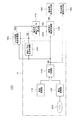
図5は、基本構成例IIの画像処理装置2が適用された実施の形態例に係る画像再生装置100の構成を示している。
この図5に示す画像再生装置100は、伝送路を介して伝送されてくる画像データを受信しての再生、またはDVD(Digital Versatile Disc)やブルーレイディスク(Blu-ray Disc(登録商標))などの記録媒体200に記録された画像データの再生、を行う画像再生装置である。
FIG. 5 shows a configuration of an
The
この画像再生装置100は、図5に示すように、伝送路を介して伝送されてくる符号化された画像データを受信する受信処理部110と、記録媒体200から符号化された画像データを読み込みする読込処理部120を備える。
また符号化された画像データを復号画像データDDに復号する復号処理部130と、復号画像データDDから動きベクトルVDを生成する動きベクトル生成処理部140を備える。
また、復号画像データDDおよび動きベクトルVDを用いて画像データを撮像した時のシャッタ速度SSDを推定するシャッタ速度推定処理部150と、動きぼけ補正パラメータ算出部170を備える。
また復号画像データDDに動きベクトルVDとシャッタ速度SSDに応じて動きぼけ量を補正する動きぼけ補正処理部160を備える。
また、動きぼけが付加されることによりジャーキネス劣化が低減された動画像を表示装置に表示させる動画像表示出力部190と、復号画像を静止画像として表示装置に表示させる静止画像表示出力部180とを備えている。
As shown in FIG. 5, the
In addition, a
In addition, a shutter speed
The decoded image data DD also includes a motion blur
In addition, a moving image
なお、一点鎖線で囲った受信処理部110,読込処理部120、復号処理部130、動きベクトル生成処理部140が、図3の基本構成例IIにおける画像取込部11に相当する部位となる。また、シャッタ速度推定処理部150が図3のシャッタ速度推定処理14に相当し、動きぼけ補正パラメータ算出部170が図3の動きぼけ補正パラメータ算出部12に相当し、動きぼけ補正処理部160が図3の動きぼけ補正処理部13に相当する。
Note that the
図5において、受信処理部110及び読込処理部120は、それぞれMPEG(Moving Picture Experts Group)規格などの画像の動き情報に基づいて予測符号化された画像データを取り込み、この画像データを復号処理部130に供給する処理部である。
ここでは、受信処理部110及び読込処理部120によって動画像として取り込まれる画像データは、単位時間を1秒とし、この単位時間に対して60フレームの画像数から構成されているものとする。すなわち、本例では、画像データがフレームレートを60[fps:frame per second]のプログレッシブ形式の単位画像から構成されているものとして以下説明する。なお、画像データはプログレッシブ形式に限定されるものではなく、フィールド画像単位で処理するインタレース方式で構成されているようにしても良い。また、フレームレートについても本実施形態で用いる60[fps]のみに限定するものではない。
In FIG. 5, a
Here, it is assumed that the image data captured as a moving image by the
なお、画像再生装置100は、外部から画像データを取り込む手段として、受信処理部110及び読込処理部120のうち少なくとも何れか一方を備えていればよい。
また、画像再生装置100は、外部から画像データを取り込むのに加えて、画像データのメタデータとして含まれているなどするシャッタ速度情報を取り込める構成にしてもよい。この場合は、前述の基本構成例Iの画像処理装置1に準じた構成となり、撮像時のシャッタ速度SSDを推定するシャッタ速度推定処理部150は不要になる。
Note that the
The
復号処理部130は、受信処理部110、又は読込処理部120から取り込んだ画像データを復号する。そして復号処理部130は、ここで復号されたデータである復号画像データDDを動きベクトル生成処理部140、シャッタ速度推定処理部150、および動きぼけ補正処理部160に供給する。
また復号処理部130は、この復号画像データDDを静止画像として処理するとき、静止画像表示出力部180にのみ復号画像データDD供給して、復号画像データDDを動画像として処理しなくてもよい。
The
Further, when processing the decoded image data DD as a still image, the
動きベクトル生成処理部140は、復号処理部130から供給される復号画像データDDから、この復号画像データDDの動き情報として、動きベクトルVDを生成する。
ここで言う動きベクトルとは、フレーム間における動画像の移動位置と移動方向とを示す情報である。
また、精度よく動体の動き情報を取得するために画素単位で動きベクトルを生成するようにすることも可能であるが、本実施形態に係る動きベクトル生成処理部140では、演算処理の負担を軽減するため、フレーム画像を複数の領域に分割した画素ブロック単位で動きベクトルを生成する。
The motion vector
The motion vector here is information indicating the moving position and moving direction of the moving image between frames.
In addition, although it is possible to generate a motion vector in units of pixels in order to obtain motion information of a moving object with high accuracy, the motion vector
なお、MPEG規格などにより符号化された画像データもの場合には、符号化情報として動きベクトルが含まれている。本実施形態ではこのような符号化情報としてのベクトルを流用して用いることも可能であり、これを採用することは処理の軽減化において有意である。
但し、この符号化用の動きベクトルは、あくまで動画像を符号化するための情報であり、符号化処理が動きベクトル以外に残差情報などと組み合わせて用いて行われるので、画像全体に亘って実際の動体の動きに応じた値を忠実に示しているとは必ずしもいえない。
このため本実施形態においては、より実際の動体の動きに忠実な動きぼけを付加するため、動きベクトル生成処理部140は、後述する処理工程によって復号画像における実際の動体の動きに応じた動きベクトルを精度良く検出するようにしている。
In the case of image data encoded according to the MPEG standard or the like, a motion vector is included as encoded information. In the present embodiment, it is also possible to divert and use such vectors as encoded information, and adopting this is significant in reducing processing.
However, the encoding motion vector is information for encoding a moving image to the last, and the encoding process is performed in combination with residual information in addition to the motion vector. It cannot necessarily be said that the value according to the actual motion of the moving object is faithfully shown.
For this reason, in this embodiment, in order to add motion blur that is more faithful to the actual motion of the moving object, the motion vector
シャッタ速度推定処理部150は、復号処理部130から供給される復号画像データDDから、画像データを撮像した時のシャッタ速度SSDの推定を行なう。また、このシャッタ速度推定処理は、動きベクトル生成処理部140から供給される動きベクトルVDを用いて、具体的には後述する処理工程により実現される。
ここで、シャッタ速度情報とは、上述したように画像データを撮像した時の、撮像画像に付加される動きぼけに影響を及ぼす情報であり、具体的には、シャッタ機能を有する撮像装置により画像データが撮像された時の各単位画像の露光時間を示す。
なおシャッタ機能としては、撮像装置において、撮像素子の駆動時間を制御する電子シャッタ、開閉機構を用いて露光時間中だけ開放して撮像素子側へレンズからの光を通すメカニカルシャッタ、及び液晶素子の透過率を制御して露光時間中だけ撮像素子側へレンズからの光を通す液晶シャッタなどによって実現される。
The shutter speed
Here, the shutter speed information is information that affects the motion blur added to the captured image when the image data is captured as described above. Specifically, the shutter speed information is captured by an imaging device having a shutter function. The exposure time of each unit image when data is imaged is shown.
Note that the shutter function includes an electronic shutter that controls the drive time of the image sensor in the image pickup apparatus, a mechanical shutter that opens only during the exposure time using an opening / closing mechanism and passes light from the lens to the image sensor side, and a liquid crystal element This is realized by a liquid crystal shutter or the like that controls the transmittance and passes light from the lens toward the image sensor only during the exposure time.
動きぼけ補正パラメータ算出部170は、具体的には後述する処理により、シャッタ速度推定処理部150から供給されるシャッタ速度情報SSD、および動きベクトル生成処理部140から供給される動きベクトルVDに基づいて、動きぼけ補正パラメータを算出し、動きぼけ補正処理部160に出力する。
Specifically, the motion blur correction
動きぼけ補正処理部160は、具体的には後述する処理により、復号処理部130から供給される復号画像データDDに対して、動きぼけ補正パラメータ算出部170から供給される動きぼけ補正パラメータに基づいて、動きぼけの補正処理を行う。
動きぼけの補正処理とは、画像データDDの各分割領域を、動きベクトルVDに含まれる各分割領域に対応した移動速度の値に応じて、ジャーキネスとブラーの発生を低減させる最適なシャッタ速度での撮像に対応する、擬似的な画像へ変換する処理であると言い換えられる。
その際、変換処理前の入力画像信号の撮像シャッタ速度SSDを参照し、各分割領域における最適シャッタ速度が、撮像シャッタ速度SSDよりも低速である場合、動きぼけを付加する処理を行い、逆に撮像シャッタ速度SSDよりも高速である場合、動きぼけを除去する処理を行うこととなる。
そして動きぼけ補正処理部160は、各分割領域を変換処理した画像を1フレーム画像に合成し、出力画像信号ODを生成し、動画像表示出力部170へと出力する。
Specifically, the motion blur
The motion blur correction process is an optimal shutter speed that reduces the occurrence of jerkiness and blur according to the value of the moving speed corresponding to each divided area included in the motion vector VD. In other words, it is a process of converting into a pseudo image corresponding to the imaging of the above.
At that time, with reference to the imaging shutter speed SSD of the input image signal before the conversion process, if the optimum shutter speed in each divided region is lower than the imaging shutter speed SSD, a process for adding motion blur is performed. When it is faster than the imaging shutter speed SSD, a process for removing motion blur is performed.
Then, the motion blur
動画像表示出力部190は、動きぼけ補正処理部160によって動きぼけが補正されることによりジャーキネス劣化とブラー劣化の双方が低減された動画像を、LCD(Liquid Crystal Display)などの表示装置に動画像として出力する。
静止画像表示出力部180は、復号処理部130から供給された復号画像データDDを静止画像として、LCDなどの表示装置に出力する。
The moving image
The still image
[4−2:動きベクトル生成処理部140]
次に図5に示した個々の処理部位についての詳細を記載する。まず最初に、動きベクトル生成処理部140の構成と動作について記述する。
動きベクトル生成処理部140は、上述したように画素ブロック単位で動きベクトルを精度良く生成する部位であって、具体的には図6に示すように、動きベクトル検出部141、画素ブロック特定処理部142、動きベクトル推定処理部143、動きベクトル平滑化処理部144、及び遅延部141a,142aを有する。
[4-2: Motion vector generation processing unit 140]
Next, details of the individual treatment sites shown in FIG. 5 will be described. First, the configuration and operation of the motion vector
As described above, the motion vector
動きベクトル検出部141は、処理対象フレームと直前フレームとから動きベクトルを検出する。
画素ブロック特定処理部142は、処理対象フレームの動きベクトルと直前フレームの動きベクトルとを画素ブロック毎に比較して、相関の高い画素ブロックを特定する。
動きベクトル推定処理部143は、画素ブロック特定処理部142により特定された画素ブロックの動きベクトルから、それ以外の画素ブロックの動きベクトルを推定する。
動きベクトル平滑化処理部144は、動きベクトルに対して平滑化処理を施す。
The motion
The pixel block
The motion vector
The motion vector smoothing
復号処理部130から供給された復号画像データDDは、動きベクトル検出部141と、復号画像データDDを1フレーム分遅延させる遅延部141aに供給される。
動きベクトル検出部141は、復号処理部130から供給された復号画像データDDを処理対象フレームとする。そして当該処理対象フレームと、遅延部141aにより1フレーム分遅延された直前フレームとから、処理対象フレームの動きベクトルを、画素ブロック単位で検出する。
なお、動きベクトル検出部141に係る処理をソフトウェアによって実装する場合には、一般的なブロックマッチング法を用いて画素ブロック単位で動きベクトルを検出すればよい。
The decoded image data DD supplied from the
The motion
When the processing related to the motion
動きベクトル検出部141で検出された動きベクトルは、画素ブロック特定処理部142と遅延部142aに供給される。遅延部142aは入力された動きベクトルを1フレーム分遅延させる。
画素ブロック特定処理部142は、動きベクトル検出部141から供給される処理対象フレームの動きベクトルと、遅延部142aにより遅延された直前フレームの動きベクトルとを、次に示すように画素ブロック単位で比較して、この比較結果から相関の高い画素ブロックを特定する。
The motion vector detected by the motion
The pixel block
具体的に、画素ブロック特定処理部142は、処理対象フレームの一の画素ブロックの動きベクトルを(x,y)とし、これに対応する直前フレームの画素ブロックの動きベクトルを(x’,y’)とし、任意に決定される相関判定係数をαとして、次の(数1)により、この画素ブロックのベクトル相関係数σを算出する。
Specifically, the pixel block
そして画素ブロック特定処理部142は、上述した(数1)から各画素ブロックのベクトル相関係数σを算出して、ベクトル相関係数σが1である画素ブロックを相関の高い動きベクトルを有するものとして特定する。
Then, the pixel block
動きベクトル推定処理部143は、画素ブロック特定処理部142でベクトル相関係数σの値が1として特定された画素ブロックの動きベクトルから、このベクトル相関係数σの値が0である画素ブロックの動きベクトルを推定する。
即ち動きベクトル推定処理部143は、前段の画素ブロック特定処理部142で、ベクトル相関係数σの値が1とされた画素ブロックが有効な動きベクトルを有しているものとして、それ以外の画素ブロック、つまりベクトル相関係数σの値が0とされ有効ではない動きベクトルを有している画素ブロックの動きベクトルを更新する。
The motion vector
That is, the motion vector
具体的な動きベクトル推定処理部143の処理工程について、図7を参照して詳細に説明する。
ステップS1において、動きベクトル推定処理部143は、処理対象フレームにおける現在の処理対象の画素ブロック(以下、注目画素ブロックという。)のベクトル相関係数σが1か0であるかを判断する。すなわち、動きベクトル推定処理部143は、この画素ブロックの動きベクトルが有効であるか否かを判断する。そして、動きベクトル推定処理部143は、この画素ブロックの動きベクトルが有効であるとき動きベクトルの値を更新せずに本処理工程を終了し、この画素ブロックの動きベクトルが有効でないときステップS2に進む。
Specific processing steps of the motion vector
In step S1, the motion vector
ステップS2において、動きベクトル推定処理部143は、注目画素ブロックに対して、その注目画素ブロックの周辺に有効なベクトルを有する周辺画素ブロックが存在するか否かを判断する。具体的には、動きベクトル推定処理部143は、周辺画素ブロックとして、この注目画素ブロックに隣接する合計8つの画素ブロックに対して有効な動きベクトルが存在するか否かを判断し、有効な動きベクトルが存在するとき、ステップS3に進み、有効な動きベクトルが存在しないとき、この注目画素ブロックの動きベクトルを更新せずに本処理工程を終了する。
In step S <b> 2, the motion vector
ここで、有効な動きベクトルが存在しない注目画素ブロックに対して、より広範囲に位置する周辺画素ブロックを用いて推定処理を行わない理由は、次の通りである。
第1の理由としては、より広範囲に位置する画素ブロックを用いて推定処理を行うことは可能であるが、仮に実現したとしても、固定時間処理で本処理工程を終了するためには、周辺画素ブロックとして扱われる画像データを一時的に記憶するための記憶領域が増大してしまうからである。
第2の理由としては、本処理工程の後段で、上述した隣接する合計8つの画素ブロックよりも広範囲の周辺画素ブロックを用いて注目画素ブロックの動きベクトルに対して平滑化処理を施すことにより、有効ではない動きベクトルを適切に補正することができるからである。
Here, the reason why the estimation process is not performed using the neighboring pixel blocks located in a wider range with respect to the target pixel block having no effective motion vector is as follows.
As a first reason, although it is possible to perform estimation processing using pixel blocks located in a wider range, even if it is realized, in order to end this processing step in fixed time processing, peripheral pixels This is because the storage area for temporarily storing image data handled as blocks increases.
As a second reason, by performing the smoothing process on the motion vector of the pixel block of interest using a wider range of peripheral pixel blocks than the total of the adjacent eight pixel blocks described above, in the subsequent stage of this processing step, This is because an invalid motion vector can be corrected appropriately.
ステップS3において、動きベクトル推定処理部143は、有効な動きベクトルを有する周辺画素ブロックの動きベクトルのみから、この注目画素ブロックの動きベクトルを推定して更新して、本処理を終了する。動きベクトル推定処理部143では、推定処理の一例として、有効な動きベクトルを有する周辺画素ブロックの動きベクトルのみを入力としたメディアンフィルタにより注目画素ブロックの動きベクトルを出力して平滑化する。
In step S3, the motion vector
動きベクトル推定処理部143は、以上のようにして、処理対象フレームの動きベクトルを画素ブロック単位で推定する。そして、動きベクトル推定処理部143は、画素ブロック特定処理部142で特定された動きベクトルを含めた動きベクトルを、動きベクトル平滑化処理部144に供給する。
The motion vector
動きベクトル平滑化処理部144は、処理対象画像を構成する各画素ブロックの動きベクトルに対して平滑化処理を施す。具体的に、動きベクトル平滑化処理部144は、平滑化処理前の注目画素ブロックの動きベクトルと上述した隣接画素ブロックよりも広範囲の周辺画素ブロックの動きベクトルとを入力I(x+i,y+j)として、下記に示す(数2)に示すようなガウス型関数により、平滑化処理後の注目画素ブロックの動きベクトルJ(x,y)を出力する。
The motion vector smoothing
動きベクトル平滑化処理部144は、処理対象フレームを構成する各画素ブロックに対して上述した平滑化処理を施して、動きベクトルVDを動きぼけ補正パラメータ算出部170に供給する。
The motion vector smoothing
このように、動きベクトル平滑化処理部144は、処理対象フレームを構成する各画素ブロックから、有効な動きベクトルを有する画素ブロックを特定し、この有効な動きベクトルからそれ以外の動きベクトルを推定する。このため精度良く実際の動体の動きに応じた動きベクトルを生成することができる。
なお、動きベクトル生成処理部140では、動きベクトル検出部141により検出した動きベクトルを、画素ブロック特定処理部142及び動きベクトル推定処理部143を介さずに、直接動きベクトル平滑化処理部144に供給して平滑化処理を施してもよい。このような処理を行った場合にも、上述した符号化情報として動きベクトルに比べて、実際の動体の動きに応じた精度の良い動きベクトルを生成することができる。
In this way, the motion vector smoothing
The motion vector
[4−3:シャッタ速度推定処理部150]
次に、シャッタ速度推定処理部150の具体的な構成例について、図8を参照して詳細に説明する。
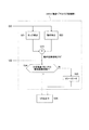
図8は、シャッタ速度推定処理部150の構成の一例を示すブロック図である。シャッタ速度推定処理部150は、処理対象領域選択部151、動きぼけ特性解析部152、撮像シャッタ速度演算部153、撮像シャッタ速度高精度化処理部154を備える。
このシャッタ速度推定処理部150は、入力された復号画像データDDおよび動きベクトルVDが入力される。そしてシャッタ速度推定処理部150は、これらの入力された情報について画像解析を行うことで画像データが撮像された際のシャッタ速度SSDを推定し、出力する。
[4-3: Shutter speed estimation processing unit 150]
Next, a specific configuration example of the shutter speed
FIG. 8 is a block diagram illustrating an example of the configuration of the shutter speed
The shutter speed
シャッタ速度推定処理部150に入力された復号画像データDDおよび動きベクトルVDは、まず処理対象領域選択部151へと入力される。
処理対象領域選択部151は、シャッタ速度の算出を目的とした画像解析を実行する処理対象フレーム、および選択されたフレーム内の処理の対象領域を選択する。そして選択された対象領域DDTとしての画像データ、および当該対象領域DDTに対応する動きベクトルVDTを、後段へと出力する。
なお後述するが、対象領域DDTとは1フレーム内でシャッタ速度推定処理の対象として抽出された領域の画像データのことである。
また処理対象領域選択部151は、動画として入力される復号画像データDDについてのシーンチェンジを検出し、シーンチェンジ検出信号SCDを撮像シャッタ速度高精度化処理部154に出力する。
The decoded image data DD and motion vector VD input to the shutter speed
The processing target
As will be described later, the target area DDT is image data of an area extracted as a target of the shutter speed estimation process within one frame.
The processing target
処理対象領域DDTは、動きぼけ特性解析部152へと入力される。処理対象領域DDTとしての画像データ(1フレーム内における処理対象領域とされた画素範囲の画像データ)は、動きぼけ特性解析部152において画像解析処理される。そして動きぼけ特性解析部152は、当該処理対象領域中に発生している動きぼけの長さ、“動きぼけ長”Lを算出する。動きぼけ長Lの定義については後述する。算出された動きぼけ長Lは、撮像シャッタ速度演算部153へと出力される。
The processing target area DDT is input to the motion blur
撮像シャッタ速度演算部153では、処理対象領域DDTにおいて発生した動きぼけ長Lの値、および当該処理対象領域に対応する動きベクトルVDTの値を用いて、撮像時のシャッタ速度を推定した値である推定撮像シャッタ速度SSDTを算出する。そして算出した推定撮像シャッタ速度SSDTを撮像シャッタ速度高精度化処理部154へと出力する。
撮像シャッタ速度高精度化処理部154には、複数の処理対象領域から推定された、各々の推定撮像シャッタ速度SSDTが入力される。撮像シャッタ速度高精度化処理部154では、これらの値を用いて高信頼度な推定撮像シャッタ速度SSDを算出し、後段へと出力する。
The imaging shutter
Each estimated imaging shutter speed SSDT estimated from a plurality of processing target areas is input to the imaging shutter speed high
ここで、図8のシャッタ速度推定処理部150の各処理ブロックで行われる処理について説明する前に、シャッタ速度推定処理部150で行われる処理の前提となる、動きぼけの特性について説明する。
シャッタ速度推定処理部150における処理は、撮像時のシャッタ速度が未知の画像からシャッタ速度を推定する処理であるが、まず基本的な動きぼけの特性を説明するため、動きぼけの発生と移動速度および撮像シャッタ速度との関係について述べる。その後に、発生する動きぼけの特性を考慮したシャッタ速度の推定方法について詳細を述べていく。
Here, before describing the processing performed in each processing block of the shutter speed
The processing in the shutter speed
動きぼけの発生と移動速度および撮像シャッタ速度との関係について、図9、図10を用いて簡単に説明する。
図9は、撮像によって発生する動きぼけの特性を説明する図である。
図9の上段は、実空間中のある領域に注目し、その空間的な位置と明るさの関係を示している。この図の例では、水平方向で空間的な位置を、垂直方向で明るさをそれぞれ表現している。またこの例では、前景が右に向かって一定の速度で移動しており、明るい前景が暗い背景へと覆い被さっていく状況を想定している。
一方、図9の下段は、上段の図で示した実空間中の注目領域を、図中の撮像装置を用いて撮像することで得られた画像信号について、その水平方向の1ラインの座標と輝度の関係をシミュレートしている。この図では、水平方向で画像信号中の座標を、垂直方向で輝度をそれぞれ表しており、点線は画素の単位を表現している。また、この撮像装置はシャッタ機能を有していることを想定しており、画像を取得する際の露光時間である、シャッタ速度を制御できるものとする。
The relationship between the occurrence of motion blur, the moving speed, and the imaging shutter speed will be briefly described with reference to FIGS.
FIG. 9 is a diagram for explaining the characteristics of motion blur caused by imaging.
The upper part of FIG. 9 focuses on a certain area in the real space and shows the relationship between the spatial position and the brightness. In the example of this figure, the spatial position is expressed in the horizontal direction, and the brightness is expressed in the vertical direction. In this example, it is assumed that the foreground is moving to the right at a constant speed, and the bright foreground covers a dark background.
On the other hand, the lower part of FIG. 9 shows the coordinates of one line in the horizontal direction for the image signal obtained by imaging the attention area in the real space shown in the upper part of the figure using the imaging device in the figure. Simulates the luminance relationship. In this figure, the coordinates in the image signal are represented in the horizontal direction, and the luminance is represented in the vertical direction, and the dotted line represents the unit of the pixel. In addition, it is assumed that the imaging apparatus has a shutter function, and it is possible to control a shutter speed, which is an exposure time when an image is acquired.
図9下段の(i)は、このシャッタ機能を用いて理想的な高速シャッタで(露光期間を無限小として)撮像した場合の画像信号であり、図9下段の(ii)は、低速シャッタで(ある一定の露光期間で)撮像した画像信号である。(i)と(ii)を比較すると、(i)がステップ関数状の信号であるのに対し、(ii)では露光期間が長い分だけ光が積分されて撮像した結果、(i)の信号に動きぼけが発生している状態が見てとれる。
この図から、画像信号中において、移動する被写体の境界付近における動きぼけは、ローパスフィルタの特性を有することがわかる。
以降においては、(ii)中に見られるように、図示した前景の輝度Bfと背景の輝度Bbが安定して記録されている領域に挟まれた、輝度値の勾配が見られる領域、を動きぼけ領域であるものと定義し、この間の距離を動きぼけ長Lと表現して用いる。
(I) in the lower part of FIG. 9 is an image signal when an image is taken with an ideal high-speed shutter (exposure period is infinitely small) using this shutter function, and (ii) in the lower part of FIG. 9 is a low-speed shutter. This is a captured image signal (with a certain exposure period). When (i) and (ii) are compared, (i) is a step function signal, whereas in (ii), the signal of (i) is obtained as a result of imaging with light integrated for a long exposure period. You can see the state of motion blur.
From this figure, it can be seen that motion blur around the boundary of the moving object in the image signal has the characteristics of a low-pass filter.
In the following, as shown in (ii), the region moves between the region where the foreground luminance Bf and the background luminance Bb shown in FIG. It is defined as a blur area, and the distance between the two is expressed as a motion blur length L.
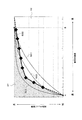
図10の左側に示す(A)(B)(C)は、被写体の移動速度と動きぼけ長Lとの関係について説明する図である。
この図10(A)(B)(C)は、図9の上段において前景の移動速度をそれぞれに変更した場合について、発生する動きぼけの特性を示している。撮像時のシャッタ速度は、図10(A)(B)(C)の全ての図に例おいて一定の値であるものとする。
(A), (B), and (C) shown on the left side of FIG.
FIGS. 10A, 10B, and 10C show characteristics of motion blur that occur when the foreground moving speed is changed in the upper part of FIG. The shutter speed at the time of imaging is assumed to be a constant value in all examples of FIGS. 10A, 10B, and 10C.
前景の移動速度を図10(A)(B)(C)のそれぞれの場合についてA、B、Cと表現するとき、移動速度の大きさには、A:B:C=3:2:1という関係があるものとする。このとき、図10(A)(B)(C)中に図示した、(A)L=9画素、(B)L=6画素、(C)L=3画素のように、動きぼけ長Lも3:2:1の関係となる。この理由は、撮像される画像信号が同じ露光期間分だけ光が積分されて記録されるため、この露光期間に被写体が移動した範囲が動きぼけ領域となるためである。
このように、移動速度を有する画素の周辺において発生する動きぼけ長Lは、被写体の移動速度の大きさに比例する、といえる。
When the moving speed of the foreground is expressed as A, B, and C in each of the cases of FIGS. 10A, 10B, and 10C, the magnitude of the moving speed is A: B: C = 3: 2: 1. It is assumed that there is a relationship. At this time, the motion blur length L is shown in FIGS. 10A, 10B, and 10C, such as (A) L = 9 pixels, (B) L = 6 pixels, and (C) L = 3 pixels. Also has a 3: 2: 1 relationship. This is because the image signal to be captured is integrated and recorded for the same exposure period, and the range of movement of the subject during this exposure period is the motion blur area.
Thus, it can be said that the motion blur length L generated around the pixel having the moving speed is proportional to the magnitude of the moving speed of the subject.
一方、図10の右側に示す(a)(b)(c)は、撮像シャッタ速度と動きぼけ長との関係について説明する図である。
この図10(a)(b)(c)は、図9の上段において撮像装置のシャッタ速度をそれぞれに変更した場合について、発生する動きぼけの特性を示している。前景の移動速度は、上図10(a)(b)(c)の例おいて一定の値であるものとする。
On the other hand, (a), (b), and (c) shown on the right side of FIG. 10 are diagrams for explaining the relationship between the imaging shutter speed and the motion blur length.
FIGS. 10A, 10B, and 10C show characteristics of motion blur that occur when the shutter speed of the imaging apparatus is changed in the upper part of FIG. The foreground moving speed is assumed to be a constant value in the examples of FIGS. 10 (a), 10 (b), and 10 (c).
撮像シャッタ速度を図10(a)(b)(c)のそれぞれの場合についてa、b、cと表現するとき、撮像シャッタ速度は、a:b:c=4:2:1という関係があるものとする。
このとき、図10(a)(b)(c)に示した(a)L=8画素、(b)L=4画素、(c)L=2画素のように、ぼけ長Lも4:2:1の関係となる。この理由は、撮像の露光期間に光が積分されて記録されるため、撮像される被写体の移動速度が一定であれば、露光期間が長いほど動きぼけ領域が長くなるためである。
このように、移動速度を有する画素の周辺において発生する動きぼけの長Lは、撮像時のシャッタ速度の大きさに比例する、といえる。
When the imaging shutter speed is expressed as a, b, and c in each of FIGS. 10A, 10B, and 10C, the imaging shutter speed has a relationship of a: b: c = 4: 2: 1. Shall.
At this time, the blur length L is 4: as in (a) L = 8 pixels, (b) L = 4 pixels, and (c) L = 2 pixels shown in FIGS. The relationship is 2: 1. This is because light is integrated and recorded during the exposure period of imaging, so that if the moving speed of the subject to be imaged is constant, the motion blur region becomes longer as the exposure period is longer.
Thus, it can be said that the length L of the motion blur that occurs around the pixel having the moving speed is proportional to the magnitude of the shutter speed at the time of imaging.
以上のように、動きぼけ長は被写体の移動速度、および、撮像シャッタ速度に比例する。
ここで動きぼけ長をL[画素]、被写体の画像信号中における移動速度をV[画素/フレーム]、撮像シャッタ速度S[秒]、動画像のフレームレートをF(フレーム/秒)表現すると、
Here, when the motion blur length is expressed as L [pixel], the moving speed in the image signal of the subject is expressed as V [pixel / frame], the imaging shutter speed S [second], and the frame rate of the moving image is expressed as F (frame / second).
例えば、図10(a)(b)(c)において、移動速度を8[画素/フレーム]として、撮像シャッタ速度を(a)S=T、(b)S=T/2、(c)S=T/4、フレームレートをF=1/Tとすると(Tはフレーム周期[秒]に相当)、
(a)L=8×T×(1/T)=8 [画素]
(b)L=8×(T/2)×(1/T)=4 [画素]
(c)L=8×(T/4)×(1/T)=2 [画素]
となり、図10(a)(b)(c)にて発生する動きぼけ長Lと等しいことが確認できる。
For example, in FIGS. 10A, 10B, and 10C, the moving speed is 8 [pixel / frame], and the imaging shutter speed is (a) S = T, (b) S = T / 2, and (c) S. = T / 4 and the frame rate is F = 1 / T (T corresponds to the frame period [second])
(A) L = 8 × T × (1 / T) = 8 [pixel]
(B) L = 8 × (T / 2) × (1 / T) = 4 [pixel]
(C) L = 8 × (T / 4) × (1 / T) = 2 [pixel]
Thus, it can be confirmed that the motion blur length L generated in FIGS.
ここまで、動きぼけの発生と、移動速度および撮像シャッタ速度との関係について、簡単な例を用いて説明したが、シャッタ速度推定処理部150の目的は、撮像シャッタ速度が未知の画像からこれを推定することであるため、上述の(数3)を、以下のように変形しておく。
この(数4)より、画像中の注目する領域が有する移動速度V、およびフレームレートF、が既知であるとすると、未知である撮像時のシャッタ速度Sを算出は、発生する動きぼけ長Lが得られれば可能であることがわかる。 From this (Equation 4), assuming that the moving speed V and the frame rate F of the region of interest in the image are known, the unknown shutter speed S at the time of imaging is calculated, and the generated motion blur length L If it is obtained, it is understood that it is possible.
さて以下では、シャッタ速度推定処理部150の構成の一例を示す図8について、各処理ブロックにおける処理内容を明らかにし、シャッタ速度推定の処理手法を説明する。
なお、撮像シャッタ速度が未知の画像からこれを推定する方法は、以下で紹介する手法に限られたものではない。ここでは例として、上で定義した動きぼけ長Lを特定することで、撮像時のシャッタ速度を算出する方法を挙げる。
Now, with reference to FIG. 8 showing an example of the configuration of the shutter speed
Note that the method of estimating this from an image with an unknown imaging shutter speed is not limited to the method introduced below. Here, as an example, a method of calculating the shutter speed at the time of imaging by specifying the motion blur length L defined above will be given.
シャッタ速度推定処理部150の入力である復号画像データDDおよび動きベクトルVDは、まず処理対象領域選択部151へと入力される。ここでは、シャッタ速度推定のための画像解析を実行する対象となる領域(以下「対象領域」という)の抽出を行い、処理対象領域DDTおよび当該対象領域DDTに対応する動きベクトルVDTを後段へと出力する。
この抽出処理は、動きぼけが発生する領域が入力された動画像信号における、当該フレームの全領域について行わなくてもよい、という前提において行う。フレーム中から何らかの方法で解析処理の対象となる対象領域を選択する必要があるわけである。
The decoded image data DD and the motion vector VD, which are inputs of the shutter speed
This extraction process is performed on the premise that it is not necessary to perform the entire region of the frame in the moving image signal in which the region where motion blur occurs is input. This is why it is necessary to select a target area to be subjected to analysis processing from the frame by some method.
ここで限定された対象領域にのみ撮像シャッタ速度の推定を行うことが問題にならない理由は、一般的に撮像時のシャッタ速度が1つのフレーム画像内において均一であることが通常であるためである。さらに、処理コストの観点からも、処理を行う対象領域が少ないことが利点となる。
上記の理由から、原理的には当該フレーム中の1ヶ所の対象領域において、シャッタ速度推定処理を行えば、その他の領域でのシャッタ速度推定は必要ないわけであるが、それでも処理コストが許容する範囲で、フレーム内で複数の対象領域を抽出してシャッタ速度推定処理を実行することは、シャッタ速度推定の精度向上のためには大変有効である。
そのため本例では、1フレーム内から複数の対象領域において下記の処理を実行し、複数得られた結果から、撮像シャッタ速度SSDを推定するものとする。複数の異なるシャッタ速度の値が推定された場合に信頼性を向上する処理は、後段の撮像シャッタ速度高精度化処理部154において実行する。その処理内容については後述する。
The reason why it is not a problem to estimate the imaging shutter speed only for the limited target region is that the shutter speed during imaging is generally uniform in one frame image. . Furthermore, from the viewpoint of processing cost, it is advantageous that there are few target areas to be processed.
For the above reasons, in principle, if shutter speed estimation processing is performed in one target area in the frame, shutter speed estimation in other areas is not necessary, but the processing cost is still acceptable. Extracting a plurality of target areas within a frame and executing shutter speed estimation processing within a range is very effective for improving the accuracy of shutter speed estimation.
For this reason, in this example, the following processing is executed in a plurality of target areas from one frame, and the imaging shutter speed SSD is estimated from a plurality of obtained results. The process of improving the reliability when a plurality of different shutter speed values are estimated is executed in the imaging shutter speed high
復号画像データDDの或る1フレーム中から、解析処理の対象となる対象領域を選択する方法について唯一に限定するものではないが、その詳細を後述する動きぼけ特性の解析処理が効果的に実行できるためには、図9、図10に示した被写体の境界エッジ周辺の領域であることが望ましい。
また、或る領域の移動速度が0である場合には、その領域では動きぼけが発生しないため、対象領域の選択の際に移動速度情報を用いて、一定の移動速度を有する領域を対象領域として選択することが望まれる。
また、エッジの方向と移動速度の方向の関係は、できるだけ直交に近い関係であると、発生する動きぼけの解析が行いやすい。
以上をまとめると、一定の移動速度を有し、なるべく移動速度の方向と直交に近い方向のエッジ周辺の領域を解析の対象領域として選択すればよい、ということとなる。
Although the method for selecting a target region to be analyzed from one frame of the decoded image data DD is not limited to a single method, the analysis processing of motion blur characteristics described later in detail is effectively executed. In order to be able to do so, the area around the boundary edge of the subject shown in FIGS. 9 and 10 is desirable.
In addition, when the movement speed of a certain area is 0, motion blur does not occur in that area. Therefore, the area having a certain movement speed is selected using the movement speed information when selecting the target area. It is desirable to select as
Also, if the relationship between the edge direction and the moving speed direction is as close to orthogonal as possible, it is easy to analyze the motion blur that occurs.
In summary, the region around the edge that has a constant moving speed and is as close to the direction of the moving speed as possible may be selected as the analysis target region.
さらに、解析を画像処理にて実現するために処理コストの観点から考えると、スキャンライン方向に画素をピックアップする方がよい。そのため、水平方向の移動速度を有する垂直方向エッジ周辺の領域が、対象領域の抽出について最も便宜がよい。このような領域を選択する場合、詳細を後述する動きぼけ特性解析処理では、複数ラインにまたがる処理は必要なく、全て1ラインの処理で実現できる。
以上をまとめると、水平方向に移動速度を持つ垂直方向のエッジ周辺の領域に注目すれば、移動速度の大きさに対し十分な画素数の水平方向の画素のみを用いて、後述する動きぼけ特性解析処理は実現できる。
Furthermore, in view of processing cost in order to realize analysis by image processing, it is better to pick up pixels in the scan line direction. Therefore, the area around the vertical edge having the horizontal movement speed is most convenient for extracting the target area. When such an area is selected, the motion blur characteristic analysis process, which will be described in detail later, does not require a process over a plurality of lines, and can be realized by a single line process.
In summary, if we focus on the area around the edge in the vertical direction that has a moving speed in the horizontal direction, only the pixels in the horizontal direction with a sufficient number of pixels with respect to the magnitude of the moving speed can be used. Analysis processing can be realized.
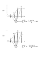
図11は対象領域の選択についてその例を示したものである。
図11(a)は復号画像データDDの或る1フレームを示している。ここまでに説明した通り、復号画像データDDに対してエッジ抽出処理、例えばsobelフィルタなどを用いてエッジ領域を抽出し、図11(b)に示したエッジデータEDのようなデータを得る。さらに、上記の説明の通り、水平の移動速度を有した垂直方向エッジ周辺の水平1ラインを選択する。例えば図中AR1〜AR5と示したような領域を対象領域とする。なお対象領域AR1〜AR5は、それぞれ水平1ライン内の一部とされればよい。
そして図11(c)のように各対象領域についての輝度情報を得る。この図11(c)は、横軸に対象領域の各画素の座標、縦軸に輝度情報を示している。
FIG. 11 shows an example of selection of the target area.
FIG. 11A shows a certain frame of the decoded image data DD. As described so far, an edge region is extracted from the decoded image data DD using an edge extraction process, for example, a sobel filter, and data such as the edge data ED shown in FIG. 11B is obtained. Further, as described above, one horizontal line around the vertical edge having a horizontal movement speed is selected. For example, an area indicated as AR1 to AR5 in the figure is a target area. The target areas AR1 to AR5 may be a part of one horizontal line.
Then, as shown in FIG. 11C, luminance information for each target area is obtained. In FIG. 11C, the horizontal axis represents the coordinates of each pixel in the target area, and the vertical axis represents the luminance information.
なお、ここまでの説明は、当該1フレーム内についてのものであったが、当該フレームの全領域に対して処理を行わなくても問題ないことと同様、対象領域の選択は全てのフレームにおいて実行しなくてもよい。その理由は、複数フレームで構成される動画像が、少なくともシーンチェンジが発生するフレームまでの間は、撮像時のシャッタ速度が一定であることが一般的であるためである。したがって、あるフレームを解析することで推定された撮像シャッタ速度は、次のシーンチェンジが検出されるまで、その値を保持すればよいこととなる。 Although the description so far has been for one frame, the selection of the target area is performed for all frames, as is the case that there is no problem even if processing is not performed for all areas of the frame. You don't have to. The reason is that a moving image composed of a plurality of frames generally has a constant shutter speed during imaging until at least a frame where a scene change occurs. Therefore, the imaging shutter speed estimated by analyzing a certain frame only needs to be held until the next scene change is detected.
このようにシャッタ速度推定処理は、シーンチェンジが検出されてから次のシーンチェンジが検出されるまでの間に、少なくともある一つのフレームで実行すればよい。しかしながら、上述したように1つのフレーム内において複数の対象領域を抽出して、それぞれの対象領域でシャッタ速度推定処理を実行するのと同様に、処理コストが許容する範囲で複数のフレームでシャッタ速度推定処理を実行することは、シャッタ速度推定の精度向上のために大変有効である。複数の異なるシャッタ速度の値が推定された場合に信頼性を向上する処理は、後述する撮像シャッタ速度高精度化処理部154において実行する。
As described above, the shutter speed estimation process may be executed in at least one frame between the detection of a scene change and the detection of the next scene change. However, as described above, a plurality of target areas are extracted in one frame, and the shutter speed estimation process is performed in each target area. Executing the estimation process is very effective for improving the accuracy of the shutter speed estimation. The process of improving the reliability when a plurality of different shutter speed values are estimated is executed by the imaging shutter speed high
ここで処理対象領域選択部151による対象領域選択処理の具体例を、図12を参照して説明する。
なお図12は、図8の構成において、処理対象領域選択部151と撮像シャッタ速度高精度化処理部154について、動作説明のために内部機能構成例を示したものである。
Here, a specific example of the target area selection processing by the processing target
FIG. 12 shows an example of the internal functional configuration for explaining the operation of the processing target
図12の例では、処理対象領域選択部151は、垂直方向エッジ検出部1511、水平方向移動速度しきい値処理部1512、対象領域判別部1513、およびシーンチェンジ検出部1514によって構成されている。
上述の通りこの例においては、1つのフレーム内から、一定以上の水平方向の速度を有した垂直方向エッジ周辺の領域を対象領域として抽出し、抽出した対象領域のみにおいてシャッタ速度推定処理を行うようにする。
In the example of FIG. 12, the processing target
As described above, in this example, an area around a vertical edge having a horizontal speed of a certain level or more is extracted as a target area from one frame, and shutter speed estimation processing is performed only on the extracted target area. To.
垂直方向エッジ検出部1511では、入力された復号画像データDDの当該フレーム中の各領域に対し、エッジ検出処理を行う。このとき、Sobelフィルタなどの方向選択型マスク処理を用いて、垂直方向のエッジのみを抽出すればよい。
垂直エッジ領域として判別された領域は、入力した当該領域の画像信号をそのまま対象領域判別部1513へと出力する。垂直エッジ領域として判別されなかった領域については、領域内の全ての画素信号を「0」にして、対象領域判別部1513へ出力するものとする。
水平方向移動速度しきい値処理部1512には、動きベクトルVDが入力される。ここで、一定以上の水平方向の速度を有した領域を選別するため、各領域の持つ動きベクトルの水平成分、ここでは水平成分VDxと表現するが、この値をしきい値処理する。
あらかじめ用意しておいたしきい値をTHとすると、水平成分VDxがしきい値THより大きい(VDx>TH)場合、入力した当該領域の動きベクトル信号をそのまま対象領域判別部1513へと出力する。水平成分VDxがしきい値THより大きくない(VDx≦TH)場合、当該領域の有する動きベクトル値をすべて「0」にして、対象領域判別部1513へ出力するものとする。
The vertical
For the area determined as the vertical edge area, the input image signal of the area is output to the target
The motion vector VD is input to the horizontal movement speed
Assuming that the threshold value prepared in advance is TH, if the horizontal component VDx is larger than the threshold value TH (VDx> TH), the input motion vector signal of the region is output to the target
対象領域判別部1513では、入力した当該領域の画像データ、および動きベクトルが双方ともに0でない場合のみ、当該領域がシャッタ速度推定処理の対象領域であるものと判断する。その場合にのみ、当該領域を対象領域DDTとする。上述したように「対象領域DDT」とは、対象領域と判定した領域の画像データのことである。
そして対象領域判別部1513は、対象領域DDTを動きぼけ特性解析部152へと出力し、また当該領域の動きベクトルVDTを撮像シャッタ速度演算部153へ出力する。
The target
Then, the target
また、処理対象領域選択部151に入力した復号画像データDDの各フレームは、シーンチェンジ検出部1514に供給され、シーンチェンジ検出処理が行われる。なおシーンチェンジの手法は、例えば特許文献2として挙げた特開2004−282318等に開示された手法を採用すればよい。もちろん他にもシーンチェンジ検出処理手法は多様に考えられる。
そしてシーンチェンジが検出された場合には、シーンチェンジ検出部1514は、シーンチェンジ検出信号SCDを撮像シャッタ速度高精度化処理部154へと出力する。
Each frame of the decoded image data DD input to the processing target
When a scene change is detected, the scene
例えば以上のようにして処理対象領域選択部151は、対象領域DDTを特定し、これを動きぼけ特性解析部152へと出力する。また、対象領域DDTの位置に対応する動きベクトルVDTを取り出し、こちらは撮像シャッタ速度演算部153へ出力する。
続いて、動きぼけ特性解析部152における処理について説明する。
ここで言う動きぼけ特性の解析とは、上記のように選択された対象領域について、その動きぼけが有する動きぼけ長L(図9(ii)、図11(c)参照)を推定する処理である。
For example, as described above, the processing target
Next, processing in the motion blur
The analysis of the motion blur characteristic referred to here is a process of estimating the motion blur length L (see FIGS. 9 (ii) and 11 (c)) of the motion blur for the target region selected as described above. is there.
動きぼけ長Lを求める方法はいくつかが考えられるが、ここでは大きく分けて2種類を説明する。
1つ目は、動きぼけの数式モデルを定義しておき、実際に画像信号中に発生した動きぼけとの誤差関数を最小にする前記数式モデル中のパラメータを発見することにより推定する方法である。
2つ目は、事前に用意しておいた動きぼけのサンプルパターンと実際に画像信号中に発生した動きぼけとのマッチングにより推定する方法である。
There are several methods for obtaining the motion blur length L. Here, two types will be described.
The first method is to define a mathematical model of motion blur and estimate it by finding a parameter in the mathematical model that minimizes an error function with motion blur actually generated in an image signal. .
The second method is an estimation method based on matching between a motion blur sample pattern prepared in advance and a motion blur actually generated in an image signal.
まず、1つ目の方法の一例を述べる。
動きぼけの影響を受けたエッジ周辺の輝度値を数式モデルで表現し、動きぼけ長を推定する手法としては、非特許文献3に示される手法が利用できる。
この方法は、エッジ周辺の各画素の座標をp、エッジ周辺に発生するぼけの中心位置の座標(未知)をp0と表し、これを用いて変数tを次の(数5)のように設定する。
なお、図9(ii)に中心位置座標p0を示している。
As a method for expressing the luminance value around the edge affected by the motion blur by a mathematical model and estimating the motion blur length, the method shown in
In this method, the coordinates of each pixel around the edge are expressed as p, the coordinates (unknown) of the blur center position generated around the edge are expressed as p0, and using this, the variable t is set as in the following (Equation 5) To do.
FIG. 9 (ii) shows the center position coordinate p0.
これを用いて、エッジ周辺の動きぼけの特性を模擬した関数式g(t)を以下のように定義する。
このとき、実際の動きぼけとの比較は、以下の(数7)を用いる。
さて、(数7)にエッジ周辺領域の画素座標pに代入、実際の動きぼけの値との距離関数を最小とするような、パラメータL、p0、Bf、Bbを見つければ、目的である動きぼけ長Lを推定することができるわけである。
距離関数を最小化するような4つの未知数を探索するためには、準ニュートン法などの数値解放を用いるのがよい。距離関数は、実画像と関数fにおいて対応する各画素値について、その差分の2乗値や絶対値の線形和を比較するのが一般的である。
上記の例では(数6)に見られるような、光学ローパスフィルタやフォーカスなどの撮像条件を加味した上で、支配的な動きぼけの特性を模擬した関数式を定義しているが、これは、図9(ii)の画像信号の例のように、シンプルな不連続関数でもよい。
If the parameters L, p0, Bf, and Bb that minimize the distance function with the actual motion blur value are substituted into the pixel coordinates p of the edge peripheral region in (Equation 7), the target motion The blur length L can be estimated.
In order to search for four unknowns that minimize the distance function, numerical release such as the quasi-Newton method may be used. In the distance function, for each pixel value corresponding to the actual image and the function f, the square value of the difference or the linear sum of absolute values is generally compared.
In the above example, the function equation that simulates the characteristic of dominant motion blur is defined in consideration of imaging conditions such as an optical low-pass filter and focus as shown in (Equation 6). As in the example of the image signal in FIG. 9 (ii), a simple discontinuous function may be used.
次に2つ目の方法の一例を説明する。
ここでは、画像信号中において上記のように処理対象として選択されたエッジ周辺の対象領域における空間周波数成分から、動きぼけの長さLを推定する方法を述べる。
図9を用いて説明した通り、移動速度を有する画素の周辺において発生する動きぼけがローパスフィルタとして表現可能である。これを利用し、周波数解析結果のマッチングによる方法で、発生する動きぼけ長Lを推定する。
Next, an example of the second method will be described.
Here, a method for estimating the length L of motion blur from the spatial frequency component in the target region around the edge selected as the processing target in the image signal as described above will be described.
As described with reference to FIG. 9, motion blur that occurs around a pixel having a moving speed can be expressed as a low-pass filter. Using this, the generated motion blur length L is estimated by a method based on matching of frequency analysis results.
図9で示した通り、動きぼけの発生は露光期間によって、その特性が決まる。移動速度が一定のとき、同じ動きぼけ長を有する動きぼけは、同一の周波数特性を持つはずである。
例えば、まず、撮像時の動きぼけが発生した図9(ii)の例のような画像信号について、あらゆる動きぼけ長を持った動きぼけのサンプルパターンを用意し、これらに対し所定の周波数解析を行い、各サンプルパターンが有する周波数成分を記憶しておく。周波数解析の具体的な方法には、フーリエ変換やウェーブレット解析などの一般的な方法のうち1つを用いればよい。
解析対象とされた対象領域が入力されると、サンプルパターンに行った処理と同様の周波数解析を行い、どのサンプルパターンの周波数成分と最も近いか、を誤差関数などによって判別する。最も近いサンプルパターンの動きぼけ長が、解析対象領域中のエッジが有する動きぼけ長Lとなる。
As shown in FIG. 9, the characteristics of motion blur are determined by the exposure period. When the moving speed is constant, motion blurs having the same motion blur length should have the same frequency characteristics.
For example, first, motion blur sample patterns having various motion blur lengths are prepared for an image signal such as the example of FIG. 9 (ii) in which motion blur at the time of imaging occurs, and predetermined frequency analysis is performed on these patterns. The frequency component of each sample pattern is stored. As a specific method of frequency analysis, one of general methods such as Fourier transform and wavelet analysis may be used.
When the target region to be analyzed is input, frequency analysis similar to the processing performed on the sample pattern is performed, and which sample pattern is closest to the frequency component is determined by an error function or the like. The motion blur length of the nearest sample pattern is the motion blur length L of the edge in the analysis target area.
図13は、周波数解析結果のマッチングによる動きぼけ長L推定の、具体的な処理方法の例について、その処理の流れを記している。
解析対象と判別されたエッジ周辺の対象領域は、高速フーリエ変換(FFT) 部1521へと入力される。ここで、当該対象領域に対し、高速フーリエ変換(FFT)の処理が行われ、当該対象領域が有する支配的な周波数成分を周波数成分マッチング部1522へと出力する。本例においては、高速フーリエ変換の結果として、各周波数におけるパワースペクトラムを算出し、その上位3つの値を持つ周波数を後段へと送ることにしている。
周波数成分マッチング部1522では、入力された当該対象領域が有する支配的な周波数成分と、最も類似した周波数パターンを持つ、動きぼけサンプルを動きぼけサンプル周波数テーブル1523から探索し、発見した動きぼけサンプルの動きぼけ長Lを出力する。
FIG. 13 shows the flow of processing for an example of a specific processing method of motion blur length L estimation by matching frequency analysis results.
The target region around the edge determined as the analysis target is input to the fast Fourier transform (FFT)
The frequency
図14は、動きぼけサンプル周波数テーブル1523の例を示すものである。これは図示するように、各種の動きぼけ長L(La・・・Lmax)のそれぞれについて、上位3つの周波数成分が記憶されたテーブルデータとされる。
周波数成分マッチング部1522は、当該対象領域が有する上位3つの周波数成分と最も近い周波数成分を有するサンプルを、図14のようなルックアップテーブルから探索する。このためには、誤差を評価する関数を用意する必要がある。例えば差の2乗を線形に足し合わせる一般的な距離関数のようなもので評価を行ってもよい。該当したサンプル動きぼけパターンが有する動きぼけ長が求めるべきLである。
FIG. 14 shows an example of the motion blur sample frequency table 1523. As shown in the figure, this is table data in which the upper three frequency components are stored for each of various motion blur lengths L (La... Lmax).
The frequency
上記までに、動きぼけのサンプルパターンと実際に画像信号中に発生した動きぼけとのマッチングにより動きぼけ長Lを推定する方法として、空間周波数成分に注目して行う方法を説明した。これに対し、実空間において、サンプルパターンと解析対象と判別されたエッジ周辺の領域の比較評価を行う方法も考えられる。言い換えれば、画像信号としてサンプル動きぼけパターンを保存しておき、実際の画像信号との誤差関数が最小になるようなサンプル動きぼけパターンを探索する方法も可能である。 So far, as a method for estimating the motion blur length L by matching the motion blur sample pattern with the motion blur actually generated in the image signal, a method performed by paying attention to the spatial frequency component has been described. On the other hand, in a real space, a method of comparing and evaluating a sample pattern and a region around an edge determined as an analysis target is also conceivable. In other words, it is possible to store a sample motion blur pattern as an image signal and search for a sample motion blur pattern that minimizes an error function with the actual image signal.
シャッタ速度推定処理部150における動きぼけ特性解析部152は、上記いずれかの方法を用いて動きぼけ長Lを推定し、出力する。出力された動きぼけ長Lは、撮像シャッタ速度演算部153へと入力される。
The motion blur
撮像シャッタ速度演算部153で行われるのは、対象領域DDT中の動きぼけが有する動きぼけ長Lと、対象領域DDTに対応する動きベクトルVDTを用いて、推定撮像シャッタ速度SSDTを求めることである。これは、換言すれば、単に上記(数4)を解くことである。
前記の通り、(数4)中のフレームレートFは既知であり、移動速度Vは対象領域DDTに対応する動きベクトルVDTの水平方向成分を用いればよく、これも既知である。また、動きぼけ特性解析部152によって動きぼけ長Lも推定されている。このため(数4)からシャッタ速度Sが簡単に求められ、これが撮像シャッタ速度演算部153が出力する推定撮像シャッタ速度SSDTとなる。
What is performed by the imaging shutter
As described above, the frame rate F in (Expression 4) is known, and the moving speed V may be the horizontal direction component of the motion vector VDT corresponding to the target region DDT, which is also known. In addition, the motion blur
最後に撮像シャッタ速度高精度化処理部154により撮像シャッタ速度SSDが生成され、出力される。
この撮像シャッタ速度高精度化処理部154には、撮像シャッタ速度演算部153において推定された推定撮像シャッタ速度SSDTが入力されるが、この場合、複数の対象領域から推定された推定撮像シャッタ速度が入力されるようにする。
先に述べたように、シャッタ速度推定処理は、原理的にはシーンチェンジが検出されてから次のシーンチェンジが検出されるまでの間に、ある1フレームの1ヶ所の領域を選択して処理を実行することで可能であるが、フレーム内の複数の対象領域、および、複数のフレームで同処理を実行することが、推定精度の向上のために有効である。このため、複数の推定撮像シャッタ速度SSDTを用いて撮像シャッタ速度SSDを生成するようにする。
このように異なる複数の推定撮像シャッタ速度SSDTが推定された場合には、加重平均値や中間値をもとめて、最終的に出力する撮像シャッタ速度SSDとすることが考えられる。そのような処理により、信頼性を向上することができる。
Finally, the imaging shutter speed
The estimated shutter speed SSDT estimated by the imaging shutter
As described above, in principle, the shutter speed estimation process is performed by selecting one area of a certain frame between the detection of a scene change and the detection of the next scene change. However, it is effective to improve the estimation accuracy to execute the same processing in a plurality of target regions in a frame and a plurality of frames. For this reason, the imaging shutter speed SSD is generated using a plurality of estimated imaging shutter speeds SSDT.
When a plurality of different estimated imaging shutter speeds SSDT are estimated in this way, it is conceivable to obtain the imaging shutter speed SSD that is finally output by obtaining a weighted average value or an intermediate value. Such processing can improve the reliability.
以下では図12により、撮像シャッタ速度高精度化処理部154の動作例を述べる。
図12の例では、撮像シャッタ速度高精度化処理部154は、撮像シャッタ速度蓄積部1541、撮像シャッタ速度フィルタ処理部1542、およびシーンチェンジ検出信号受信部1543によって構成されている。
Hereinafter, an operation example of the imaging shutter speed high
In the example of FIG. 12, the imaging shutter speed high
撮像シャッタ速度演算部153により対象領域について算出された推定撮像シャッタ速度SSDTは、撮像シャッタ速度高精度化処理部154に入力すると、まず撮像シャッタ速度蓄積部1541に入り、その値を蓄積するものとする。
撮像シャッタ速度フィルタ処理部1542は、撮像シャッタ速度蓄積部1541に蓄積された1つ以上の推定撮像シャッタ速度SSDTの値を用いて、これに所定のフィルタ処理を行う。先に述べた通り、この処理は、異なる複数の推定撮像シャッタ速度SSDTの値が入力された場合における、信頼度向上の効果を期待して行うものである。フィルタの内容は、平均化処理、加重平均化処理、中間値検出処理などを行えばよい。
また、撮像シャッタ速度蓄積部1541に蓄積する推定撮像シャッタ速度SSDTの値のデータ量を軽減するためには、IIRフィルタを用いれば、直前の処理結果のみを保持すればよく、効率的である。
When the estimated imaging shutter speed SSDT calculated for the target area by the imaging shutter
The imaging shutter speed
In order to reduce the data amount of the estimated imaging shutter speed SSDT accumulated in the imaging shutter
シーンチェンジ検出信号受信部1543は、処理対象領域選択部151中のシーンチェンジ検出部1514から入力されたシーンチェンジ検出信号SCDを受信する。シーンチェンジ検出信号SCDを受信した場合、当該処理フレームにおいて、シーンチェンジが起こったものとみなし、その結果、撮像シャッタ速度が変更になるものとみなす。
その場合、シーンチェンジ検出信号受信部1543は、リセット信号を撮像シャッタ速度蓄積部1541へと出力し、蓄積されているこれまでの撮像シャッタ速度の推定値を削除する。以降、撮像シャッタ速度フィルタ処理部1542は、撮像シャッタ速度蓄積部1541に新たに入力した、撮像シャッタ速度の推定値を用いて、信頼性の高い撮像シャッタ速度の算出を行っていく。
The scene change detection
In that case, the scene change detection
このような動作による撮像シャッタ速度フィルタ処理部1542の処理結果が、当該フレームの、また、当該シーン(直前にシーンチェンジが検出されてから次にシーンチェンジが検出されるまで)の、撮像シャッタ速度SSDとして出力される。
The processing result of the imaging shutter speed
以上が、シャッタ速度推定処理部150における一連のシャッタ速度の推定方法の説明である。上記までの手法により推定されたシャッタ速度SSDは、動きぼけ補正パラメータ算出部170へと出力される。
The above is the description of the series of shutter speed estimation methods in the shutter speed
[4−4:動きぼけ補正パラメータ算出部170及び動きぼけ補正処理部160]
次に、図5に示した動きぼけ補正パラメータ算出部170及び動きぼけ補正処理部160で行われる処理について説明する。
動きぼけ補正パラメータ算出部170及び動きぼけ補正処理部160における処理の目的は、復号画像データDDの各分割領域(図2参照)を、シャッタ速度推定処理部150から入力した撮像シャッタ速度SSDを参照しつつ、動きベクトル生成処理部140から入力した動きベクトルVDの値に応じてフィルタリング処理を実行し、ジャーキネスとブラーの双方の発生が低減された出力画像を動画像表示出力部190へと出力するものである。
その際に実行する動きぼけ補正処理とは、分割領域ごとに動きぼけを削減または付加するフィルタリング処理であり、フィルタリング処理選択は具体的には後述する手法により、適応的に行なわれる。
[4-4: Motion blur correction
Next, processing performed by the motion blur correction
The purpose of the processing in the motion blur correction
The motion blur correction process executed at this time is a filtering process for reducing or adding motion blur for each divided region, and the filtering process selection is specifically performed adaptively by a method described later.
図15は、動きぼけ補正パラメータ算出部170及び動きぼけ補正処理部160の具体的な構成例を示すものである。動きぼけ補正パラメータ算出部170は、処理選択制御部171と最適シャッタ速度情報記憶部172を備える。
動きぼけ補正処理部160は、分岐部163、動きぼけ削減処理部164、動きぼけ付加処理部165、合成部166を備える。
FIG. 15 shows a specific configuration example of the motion blur correction
The motion blur
上述した動きベクトル生成処理部140から出力された動きベクトルVD、及びシャッタ速度推定処理部150から出力された撮像シャッタ速度SSDは、まず処理選択制御部171へと入力される。
処理選択制御部171では、入力された動きベクトルVD中の当該分割領域に対応するベクトルの値を用いて、最適シャッタ速度情報記憶部172に記憶してあるデータである最適シャッタ速度情報を参照し、当該分割領域における最適シャッタ速度SSD0を導出する。
そして処理選択制御部171はさらに、シャッタ速度推定処理部150から供給された撮像シャッタ速度SSDと、最適シャッタ速度SSD0を比較評価する。これにより当該分割領域に対して実行すべきフィルタリング処理が、動きぼけの削減処理なのか、或いは動きぼけの付加処理なのか、或いは動きぼけ補正処理不要かを判断し、それを伝達する処理選択制御情報SCSを分岐部163へと出力する。
The motion vector VD output from the motion vector
The process
Then, the process
また、処理選択制御部171は、選択された動きぼけ補正用のフィルタリング処理ブロック、すなわち、動きぼけ削減処理部164および動きぼけ付加処理部165へと、フィルタリング処理に必要な、フィルタパラメータPDを出力する。動きぼけ補正は、動きぼけの削減または付加のいずれかの処理によって実現されるわけであるが、フィルタパラメータPDは、その処理の具合(量/強度)を調整するために用いられる。
Further, the process
分岐部163へは、復号画像データDDが既に入力されており、処理選択制御情報SCSに応じて、分割領域毎に、動きぼけ削減処理部164または動きぼけ付加処理部165の選択された方へと出力する。
なお分岐部163は、動きぼけ補正が不要と判断された分割領域については、動きぼけ削減処理部164または動きぼけ付加処理部165に供給せずに合成部166に出力するようにしてもよい。但しここでは、動きぼけ補正が不要と判断された分割領域については、動きぼけ削減処理部164または動きぼけ付加処理部165で補正量ゼロとして処理されるものとする。
The decoded image data DD has already been input to the branching
It should be noted that the branching
動きぼけ削減処理部164では、分岐部163から供給される分割領域毎の画像データについて、詳しくは後述する手法で、動きぼけ量を減少させるフィルタリング処理を実行し、合成部166へと出力する。
動きぼけ削減処理部165では、分岐部163から供給される分割領域毎の画像データについて、詳しくは後述する手法で、動きぼけ量を増加させるフィルタリング処理を実行し、合成部166へと出力する。
合成部166へと出力された、各分割領域のフィルタリング処理後の画像信号は、この合成部166で各フレーム画像へと再構成され、出力画像信号ODとして、出力される。
The motion blur
The motion blur
The image signal after filtering processing of each divided region output to the combining
以降、図15に示した構成例の各処理ブロックにおける処理を順に説明していく。
またその過程で、動きぼけ補正処理部160で行われる処理を理解する上でポイントとなる、前記最適なシャッタ速度情報について詳細な説明、前記動きぼけ削減処理と動きぼけ付加処理の選択方法についての説明、および双方のフィルタリング処理の具体的な実現方法について例を挙げた説明を加えていく。
Hereinafter, processing in each processing block of the configuration example illustrated in FIG. 15 will be described in order.
Further, in the process, a detailed description of the optimum shutter speed information, which is a point in understanding the processing performed by the motion blur
処理選択制御部171で実行される最初の処理は、入力された動きベクトルVD中の当該分割領域に対応するベクトルの値を用いて、事前から最適シャッタ速度情報記憶部172に記憶されているデータである最適シャッタ速度情報を参照し、当該分割領域における最適シャッタ速度SSD0を導出する、ことであった。
そのため、処理選択制御部171の処理内容を述べる前に、最適シャッタ速度そのものについて説明しておく。
The first process executed by the process
Therefore, before describing the processing contents of the processing
図16は、動きベクトルとして検出される動体の移動速度を示す被写体速度と、この被写体速度に応じた最適シャッタ速度曲線を表した図である。
ある移動速度に対する最適なシャッタ速度とは、もし仮にそのシャッタ速度で実際の撮像が行なわれた場合、ジャーキネス劣化と動きぼけ劣化の双方が低減される、という値である。即ち最適シャッタ速度とは、被写体の移動速度に応じた、視覚特性上、ジャーキネス劣化が知覚されにくく、且つ、動きぼけが過度に付加されることによって被写体のディテールが欠損したり不鮮明になるぼけ劣化も知覚されにくいシャッタ速度である。
また、動きぼけ量は撮像時の露光期間であるシャッタ速度の値が大きくなるほど増加する関係にある。
そして、この最適シャッタ速度よりも速いシャッタ速度で被写体を撮像すると、撮像画像には、ジャーキネス劣化が生じていると判断できる。一方、この最適シャッタ速度よりも遅いシャッタ速度で被写体を撮像すると、撮像画像には、ぼけ劣化が生じていると判断することができる。
FIG. 16 is a diagram showing a subject speed indicating a moving speed of a moving object detected as a motion vector and an optimum shutter speed curve corresponding to the subject speed.
The optimum shutter speed for a certain moving speed is a value that, if actual imaging is performed at the shutter speed, both jerkiness deterioration and motion blur deterioration are reduced. In other words, the optimal shutter speed means that the jerkiness degradation is difficult to perceive due to the visual characteristics according to the moving speed of the subject, and the subject details are lost or blurred due to excessive motion blur. The shutter speed is also difficult to perceive.
Also, the amount of motion blur has a relationship that increases as the value of the shutter speed, which is the exposure period during imaging, increases.
When a subject is imaged at a shutter speed faster than the optimum shutter speed, it can be determined that jerkiness deterioration has occurred in the captured image. On the other hand, if a subject is imaged at a shutter speed slower than the optimum shutter speed, it can be determined that the captured image has been blurred.
最適シャッタ速度情報記憶部172は、この図16で表現するような最適なシャッタ速度の情報を事前に有している箇所であり、これを動きぼけ量調整の基準として用いて、後段の動きぼけ量を調整するフィルタリング処理の内容を決定する。言い換えれば、後段の動きぼけ削減処理部164および動きぼけ付加処理部165で行われるフィルタリング処理は、画像中の各領域を“最適なシャッタ速度で撮像された相当”の動きぼけを含んだ画像に変換する処理、と言える。
The optimum shutter speed
図16の最適シャッタ速度曲線SS0は、任意の被写体速度と最適なシャッタ速度との対応関係を示した一例であって、具体的には心理実験に基づいて得られた実験結果値を結んだ曲線である。ここで、図16に示す動きぼけ領域A1は、最適シャッタ速度曲線SS0に基づいて、被写体の動きによる動きぼけが過度に含まれると判別される領域である。同様にして、ジャーキネス領域A2は、最適シャッタ速度曲線SS0に基づいて、被写体の動きによる動きぼけが含まれず、視覚特性上ジャーキネス劣化が生じていると判別される領域である。
この最適シャッタ速度曲線SS0を直接用いて動きベクトルに応じた最適シャッタ速度を求める場合には、任意の刻み幅で動きベクトルに応じた最適シャッタ速度情報をテーブルとして最適シャッタ速度情報記憶部172に予め記憶し、参照すればよい。
The optimum shutter speed curve SS0 in FIG. 16 is an example showing a correspondence relationship between an arbitrary subject speed and the optimum shutter speed, and specifically, a curve connecting experimental result values obtained based on a psychological experiment. It is. Here, the motion blur area A1 shown in FIG. 16 is an area where it is determined that the motion blur due to the motion of the subject is excessively included based on the optimum shutter speed curve SS0. Similarly, the jerkiness area A2 is an area where it is determined that jerkiness deterioration has occurred in visual characteristics based on the optimum shutter speed curve SS0 without motion blur due to the movement of the subject.
When the optimum shutter speed curve SS0 is directly used to obtain the optimum shutter speed corresponding to the motion vector, the optimum shutter speed information corresponding to the motion vector at an arbitrary step size is stored in the optimum shutter speed
また本例では、この実線で示された最適シャッタ速度曲線に近似する関数を用いることにより、動きベクトルに応じた最適シャッタ速度を算出するようにしてもよい。この場合、処理選択制御部171は、ある分割領域での動きベクトルをvとして、下記の(数8)に示す最適シャッタ速度曲線の近似関数により最適シャッタ速度SSD’を算出する。
このように、SS0は主観評価実験により得られた値を基に作成した最適シャッタ速度曲線であり、SS1〜SS3はこれを上記(数8)で近似させた最適シャッタ速度曲線である。SS1〜SS3は、例えば装置の使用者の嗜好によって、この最適シャッタ速度曲線を調整するために用いることが可能である。 As described above, SS0 is an optimum shutter speed curve created based on the values obtained by the subjective evaluation experiment, and SS1 to SS3 are optimum shutter speed curves obtained by approximating them by the above (Equation 8). SS1 to SS3 can be used to adjust this optimum shutter speed curve, for example, according to the preference of the user of the apparatus.
なお、最適シャッタ速度情報記憶部172に保存されるデータの形式は、図16のグラフ曲線や(数8)のような数式での表現のみならず、最適シャッタ速度曲線を量子化したテーブルを持つことなども可能である。
以上において、ジャーキネスとブラー双方の劣化の発生を最も低減させる最適なシャッタ速度について説明した。
Note that the format of data stored in the optimum shutter speed
In the foregoing, the optimum shutter speed that most reduces the occurrence of both jerkiness and blur has been described.
最適シャッタ速度情報記憶部172が図16のグラフ曲線の形式で最適なシャッタ速度情報を有しているとして、処理選択制御部171で行なわれる当該分割領域における最適シャッタ速度SSD0の導出方法を説明する。
Assuming that the optimum shutter speed
動きベクトルVD中の当該分割領域に対応するベクトルの値から、その絶対値を計算したものを、当該分割領域の移動速度AVTと表現すると、移動速度AVTの値を図16のグラフの横軸にとり、対応する曲線上の点を見つけ、さらにその曲線上の点に対応する縦軸の値を見つける。そのときの縦軸の値が、当該分割領域における最適シャッタ速度SSD0である。 When the absolute value calculated from the vector value corresponding to the divided area in the motion vector VD is expressed as the moving speed AVT of the divided area, the horizontal axis of the graph of FIG. Find a point on the corresponding curve, and then find a value on the vertical axis corresponding to the point on the curve. The value on the vertical axis at that time is the optimum shutter speed SSD0 in the divided area.
図17は、処理選択制御部171で行なわれる処理の流れを示すものである。
処理選択制御部171では、ステップS10として、上記の要領で当該分割領域における最適シャッタ速度SSD0を導出する。そしてステップS11で、導出した最適シャッタ速度SSD0と、既に処理選択制御部171に入力している撮像シャッタ速度SSDとを比較評価する。そしてその比較結果として、当該領域に対して実行するフィルタリング処理が、動きぼけの削減処理なのか、あるいは、動きぼけの付加処理なのか、を選択する。
その選択処理の基準は、各領域における最適シャッタ速度が撮像シャッタ速度SSDよりも低速である場合、ブラーを付加する処理を行いものとし(S12)、逆に撮像シャッタ速度SSDよりも高速である場合、ブラーを削減する処理を行うものとする(S13)ということとなる。
FIG. 17 shows the flow of processing performed by the processing
In step S10, the process
The standard of the selection process is that when the optimum shutter speed in each region is lower than the imaging shutter speed SSD, the process of adding blur is performed (S12), and conversely, the speed is higher than the imaging shutter speed SSD. In other words, a process for reducing blur is performed (S13).
また図15に示したように、処理選択制御部171は、選択された動きぼけ補正用のフィルタリング処理ブロック、すなわち、動きぼけ削減処理部164および動きぼけ付加処理部165へと、フィルタパラメータPDを出力する。このフィルタパラメータPDは、動きぼけの削減および付加処理において、選択された処理の具合(量/強度)を調整するためのものである。特に本例では、各分割領域における撮像シャッタ速度と最適シャッタ速度の差分値であるシャッタ速度差分値SSDD、および動きベクトルVDの双方をフィルタパラメータPDとして、動きぼけ削減処理部164および動きぼけ付加処理部165の各々へと出力することとする。
シャッタ速度差分値SSDDは、処理選択制御部171にて、動きぼけ補正の内容を動きぼけ削減処理とするか付加処理とするか、を判断する段階で行う比較評価の際に算出しておけばよい。SSDD=SSD−SSD0の式からシャッタ速度差分値を算出することとすれば、シャッタ速度差分値SSDDが正の場合に動きぼけ削減処理、負の場合に動きぼけ付加処理を実行することとなる。
Also, as shown in FIG. 15, the process
The shutter speed difference value SSDD may be calculated at the time of comparative evaluation performed at the stage where the process
図18は、図16に撮像シャッタ速度と被写体速度(被写体の移動速度)の具体例を加えて記したものである。
この例を用いて、動きぼけ削減と動きぼけ付加のどちらのフィルタリング処理を実行するか、その選択について具体的に説明するとともに、双方のフィルタリングの実現例をそれぞれ説明する。
図18中では、撮像時のシャッタ速度の例として撮像シャッタ速度Sa〜Sc、被写体の移動速度の例として被写体速度Va〜Vcを記載している。便宜上、最適シャッタ速度曲線は、図16中からSS0のみを選択して以降の説明に用いるが、これは図16中のSS0〜SS3のどれを選択して用いても問題ない。
FIG. 18 is a diagram in which specific examples of the imaging shutter speed and the subject speed (subject moving speed) are added to FIG.
Using this example, the selection of whether to perform filtering processing for motion blur reduction or motion blur addition will be specifically described, and implementation examples of both filtering will be described.
In FIG. 18, imaging shutter speeds Sa to Sc are shown as examples of shutter speeds at the time of imaging, and subject speeds Va to Vc are shown as examples of subject moving speeds. For convenience, the optimum shutter speed curve is used in the following description after selecting only SS0 from FIG. 16, but there is no problem even if any of SS0 to SS3 in FIG. 16 is selected and used.
以下では、撮像シャッタ速度について3つの場合に分け、それぞれの場合における動きぼけ量調整処理についてその概要を説明する。それぞれの場合の例として、図18の撮像シャッタ速度の値Sa、Sb、Scを用いて説明する。 Hereinafter, the imaging shutter speed is divided into three cases, and the outline of the motion blur amount adjustment processing in each case will be described. As an example of each case, description will be given using imaging shutter speed values Sa, Sb, and Sc of FIG.
<1>撮像シャッタ速度が図18のSaの場合
この場合、撮像シャッタ速度がオープンシャッタであり、被写体速度がVa、Vb、Vcの全ての場合において、最適なシャッタ速度は実際の撮像シャッタ速度Saよりも高速である。そのため、最適なシャッタ速度相当の動きぼけを含んだ画像を生成するためには、何らかの方法で動きぼけを削減する処理、いわゆるデ・ブラー(de-blur)処理を行って実現しなければならない。
この場合、処理選択制御部171は、動きぼけ削減処理を選択したことを伝達する処理選択制御情報SCSを分岐部163へと出力することとなり、分岐部163では入力された復号画像データDD中の各分割領域の信号を、動きぼけ削減処理部164へと出力する。
<1> When Imaging Shutter Speed is Sa in FIG. 18 In this case, when the imaging shutter speed is an open shutter and the subject speeds are all Va, Vb, and Vc, the optimum shutter speed is the actual imaging shutter speed Sa. Faster than. Therefore, in order to generate an image including motion blur corresponding to the optimum shutter speed, it is necessary to perform a process for reducing motion blur by a certain method, that is, a so-called de-blur process.
In this case, the process
以下、動きぼけ削減処理部164で行われる動きぼけ削減の実現方法を、例を挙げて説明する。
具体的には例えば動きぼけ削減処理部164は、図19の構成とする。
図19の動きぼけ削減処理部164は、移動平均フィルタ特性変換部1641、移動平均フィルタ1642、減算部1643、加算部1644から構成されており、入力された復号画像データDD中の当該分割領域に対して、動きぼけ量の削減を実現する。
Hereinafter, a method for realizing motion blur reduction performed by the motion blur
Specifically, for example, the motion blur
The motion blur
なお移動平均フィルタ1642として用いる移動平均フィルタとは、最も簡易なローパスフィルタの一種であり、処理対象画素が1画素移動する毎に、周辺画素との平均値を算出して出力するフィルタである。例えばある時点では、図20(a)のように現在のサンプル値を含めてn個(図では4個)のサンプルで平均をとる。次の時点でも図20(b)のように現在のサンプル値を含めてn個(図では4個)のサンプルで平均をとる。ここでいうサンプル値が画素値となり、処理対象画素が1画素移動する毎に、処理対象画素を含む周辺画素のnサンプルの平均を出力するものとする。
The moving average filter used as the moving
移動平均フィルタ特性変換部1641には、フィルタパラメータPDが入力している。移動平均フィルタ特性変換部1641では、復号画像データDD中の当該分割領域に位置的に対応するフィルタパラメータを入力されたフィルタパラメータPDから抽出し、これに基づいて移動平均フィルタ1642にて行われる処理のフィルタ特性を決定する。
例えば、複数のフィルタパラメータPDに対して、移動平均フィルタを1つずつ予め用意しておき、注目画素において用いるべきフィルタを決定すればよい。具体的には、以下のように行う。
A filter parameter PD is input to the moving average filter
For example, one moving average filter is prepared in advance for each of the plurality of filter parameters PD, and a filter to be used in the target pixel may be determined. Specifically, this is performed as follows.
移動平均フィルタの特性を、注目画素周辺の何画素について平均処理を実行するか、と置き換えて考え、フィルタパラメータの一例としてシャッタ速度差分値SSDDと動きベクトルVDの双方を用いることとする。このとき、シャッタ速度差分値SSDDと動きベクトルVDの組合せ1つに対して、移動平均フィルタに用いる画素数を1つ決定するテーブルを用意しておき、各領域のシャッタ速度差分値SSDDと動きベクトルVDが入力するたびに、移動平均フィルタに用いる画素数を出力する。
決定された移動平均フィルタに用いる画素数は、移動平均フィルタ部1642へと出力される。
Considering the characteristics of the moving average filter as to how many pixels around the pixel of interest are subjected to the average processing, both the shutter speed difference value SSDD and the motion vector VD are used as examples of filter parameters. At this time, for each combination of the shutter speed difference value SSDD and the motion vector VD, a table for determining one pixel to be used for the moving average filter is prepared, and the shutter speed difference value SSDD and the motion vector of each region are prepared. Each time VD is input, the number of pixels used for the moving average filter is output.
The determined number of pixels used for the moving average filter is output to the moving
移動平均フィルタ部1642(ローパスフィルタ)は、処理対象の当該フレーム内の注目画素を含む所定のブロックに対して、移動平均フィルタ特性変換部1641により特性が決定された移動平均フィルタをかけることで、注目画素の画素値を変換する。移動平均フィルタ部1642により変換された注目画素の画素値は、減算部1643へと出力される。
すなわち、減算部1643には、移動平均フィルタ部1642により変換された注目画素の画素値が極性反転されて入力される。減算部1643にはまた、入力された復号画像データDD中の処理対象のフレームのうちの注目画素が入力されている。
減算部1643は、入力画像データDD中の当該画素の画素値と、移動平均フィルタ部1642により変換された注目画素の画素値との差分を求め、その差分値を加算部1644へと出力する。
このようにして、加算部1644には、移動平均フィルタ前後の差分が入力される。加算部1644にはまた、復号画像データDD中の処理対象のフレームのうちの注目画素が入力されている。加算部1644は、注目画素の補正前の画素値に対して、移動平均フィルタ前後の差分値を加算し、その加算結果を出力画像(その一部)として出力する。
The moving average filter unit 1642 (low-pass filter) applies a moving average filter whose characteristics are determined by the moving average filter
That is, the pixel value of the pixel of interest converted by the moving
The
In this way, the difference before and after the moving average filter is input to the adding
以上が、図19の構成例における動きぼけ削減処理部164の処理内容であるが、この処理の意味を理解するためには、周波数領域で考えるとわかりやすい。
減算部1643の出力信号である移動平均フィルタ前後の差分を周波数領域で考えた場合、着目された周波数において、入力された画像信号のゲインと、移動平均フィルタがかけられた後の画像信号のゲインとの差分が、減算部1643の出力信号のゲインとなる。さらに、加算部1644の出力画像信号のゲインは、入力された画像信号のゲインに対して、移動平均フィルタ前後の差分ゲインが加算された値となる。すなわち、各周波数のそれぞれにおいて、出力画像信号のゲインは、入力画像のゲインに比較して、移動平均フィルタ前後の差分ゲイン分だけ持ち上げられてことになる。
移動平均フィルタがローパスフィルタであることを踏まえ、上記の内容を換言すると、図19の構成例に示す動きぼけ削減処理部164全体では、ハイパスフィルタをかける処理と基本的に等価な処理を実行していることになる。
The above is the processing content of the motion blur
When the difference before and after the moving average filter, which is the output signal of the
In light of the fact that the moving average filter is a low-pass filter, in other words, the motion blur
なお特許文献3(特開2006−81150号公報)では、当該分割領域に直接ハイパスフィルタを実行することで動きぼけ削減処理を実現する方法も提案している。しかし、ハイパスフィルタの例として、移動平均フィルタの伝達関数の逆関数の採用を前提としており、移動平均フィルタの周波数特性にはゲインが0となる周波数が含まれているため、完全な逆移動平均フィルタが生成できないことを問題としている。処理の簡易な実現のためにも、図19の構成例に示す動きぼけ削減処理部164のようなローパスフィルタのみによる実現の方が適していると考えられるため、本例では、これを採用することが好ましい。
Note that Japanese Patent Laid-Open No. 2006-81150 also proposes a method for realizing motion blur reduction processing by directly executing a high-pass filter on the divided area. However, as an example of the high-pass filter, it is assumed that the inverse function of the transfer function of the moving average filter is adopted, and the frequency characteristic of the moving average filter includes a frequency at which the gain is 0. The problem is that the filter cannot be generated. For simple realization of processing, it is considered that the realization by only the low-pass filter such as the motion blur
以上に示した例などを用いて、動きぼけ削減処理の実現が可能である。当然ながら、動きぼけ量の削減方法は、上記に限られるものではない。 The motion blur reduction process can be realized using the example described above. Of course, the method for reducing the amount of motion blur is not limited to the above.
<2>撮像シャッタ速度が図18のSbの場合
この場合、撮像シャッタ速度が十分に速い場合であり、被写体速度がVa、Vb、Vcの全ての場合において、最適なシャッタ速度は実際の撮像シャッタ速度Sbよりも低速である。そのため、最適なシャッタ速度相当の動きぼけを含んだ画像を生成するためには、何らかの方法で動きぼけを付加する処理、いわゆるアド・ブラー(ad-blur)処理を行って実現しなければならない。
<2> When the imaging shutter speed is Sb in FIG. 18 In this case, the imaging shutter speed is sufficiently high, and the optimum shutter speed is the actual imaging shutter when the subject speed is all of Va, Vb, and Vc. The speed is lower than the speed Sb. Therefore, in order to generate an image including motion blur corresponding to the optimum shutter speed, it is necessary to perform processing that adds motion blur by some method, that is, so-called ad-blur processing.
この場合、処理選択制御部171は、動きぼけ付加処理を選択したことを伝達する処理選択制御情報SCSを分岐部163へと出力することとなり、分岐部163では復号画像データDD中の各分割領域の信号を、動きぼけ付加処理部165へと出力する。
以下、動きぼけ付加処理部165で行われる動きぼけ付加の実現方法を、例を挙げて説明する。ここでは空間フィルタリングにより出力画像の生成を行う場合を例とする。
In this case, the process
Hereinafter, a method for realizing motion blur addition performed by the motion blur
動きぼけ付加処理部165は、図21に示すように、動きぼけを付加する画像領域を特定する動きベクトルマスク情報を生成する動きベクトルマスク処理部1651と、動きベクトルを補正する動きベクトル補正部1652を有する。また処理対象フレームの各画素に応じた動きぼけ付加のためのフィルタパラメータを算出するフィルタパラメータ算出部1653と、処理対象フレームの各画素の画素値に対して動きぼけフィルタ処理を施す動きぼけ付加フィルタ1654を有する。
As shown in FIG. 21, the motion blur
ここで、画素単位で全ての処理を行うことも可能であるが、演算処理の負担を軽減するため、動きぼけ付加処理部165では、動きベクトルマスク処理部1651及び動きベクトル補正部1652に係る処理を、画素ブロックとしての分割領域単位で行うものとしている。
また、フィルタパラメータ算出部1653、及び動きぼけ付加フィルタ部1654、復号画像データDDに動きぼけを付加するフィルタ処理に当たるため、画素ブロックではなく、画素単位で行う。
Here, it is possible to perform all processing in units of pixels. However, in order to reduce the burden of calculation processing, the motion blur
In addition, since the filter
動きベクトルマスク処理部1651は、処理対象フレームのうち、動きぼけを付加する画像領域を特定するため、供給される分割領域単位の動きベクトルVDに対して、図22に示すようなマスク処理を施して、マスク処理後の分割領域単位の動きベクトルを動きベクトル補正部1652に供給する。
ここで、動きぼけを付加する必要がある、ジャーキネス劣化が発生しやすい画像領域は、特に画面内の動体画像領域及びエッジ周辺の画像領域に集中する。
よって、動きベクトルマスク処理部1651では、図22に示す処理により、ジャーキネスが発生しやすい、空間コントラストの高いエッジ周辺の画素ブロックの動きベクトルだけ有効な値として出力する。すなわちステップS21において、動きベクトルマスク処理部1651は、分岐部163から供給される復号画像データDDに対し、画素ブロック単位で、処理対象フレーム内の空間コントラストの高い領域を特定するための処理として画像のエッジを検出する。
またステップS21の処理と並列して、ステップS22において、動きベクトルマスク処理部1651は、処理対象フレーム内の動体領域を特定するための処理として、フレーム間での差分を画素ブロック単位で算出することによって動体画像領域を検出する。
The motion vector
Here, an image area that needs to be subjected to motion blur and is likely to cause jerkiness deterioration is particularly concentrated on a moving body image area and an image area around an edge in the screen.
Therefore, the motion vector
In parallel with the processing in step S21, in step S22, the motion vector
ステップS23において、動きベクトルマスク処理部1651は、上述したステップS21及びS22の何れか一方又は両方に係る処理で、ジャーキネス劣化が発生しやすい領域として検出されたか否かを、画素ブロック単位で判断する。そして、ジャーキネス劣化が発生しやすい領域と判断した画素ブロックに対して、動きベクトルマスク処理部1651は、マスク処理用のフラグを「1」に設定する。また、ジャーキネスが発生しやすい領域と判断されなかった画素ブロックに対して、動きベクトルマスク処理部1651は、マスク処理用のフラグを「0」に設定する。
In step S23, the motion vector
ステップS24において、動きベクトルマスク処理部1651は、処理選択制御部171から供給される動きベクトルVDに対して、上述したフラグが「1」に設定されている画素ブロックの動きベクトルVDであるか否かを判断する。
動きベクトルマスク処理部151は、フラグが「1」に設定されている画素ブロックの動きベクトルに対しては、その値を変えずに、後段の動きベクトル補正部1652に出力する(S24→S26)。
また、動きベクトルマスク処理部1651は、フラグが「0」に設定されている画素ブロックの動きベクトルに対しては、ステップS25において、動きベクトルの値を0又は無効にするマスク処理を施して、後段の動きベクトル補正部1652に出力する(S24→S25→S26)。
In step S24, the motion vector
The motion vector
In addition, the motion vector
次に、動きベクトル補正部1652における処理は、入力している当該領域のシャッタ速度差分値SSDDを用いて、動きベクトルVDを補正する処理である。
動きぼけ付加処理部1652で処理されているのは、シャッタ速度差分値SSDDが負の場合である。また動画像である復号画像データDDのフレームレートをF(フレーム/秒)と表すとき、0(秒)よりは小さくなりえない撮像シャッタ速度SSDと、1/F(秒)よりも大きくなりえない最適シャッタ速度SSD0、の差分値であるシャッタ速度差分値SSDDは、−1/F(秒)より小さくはならない。
Next, the process in the motion
The motion blur
後段で行われる動きぼけを付加する処理は、シャッタ速度差分値SSDDが小さいほど(差の絶対値が大きいほど)、付加するぼけ量は大きくなり、シャッタ速度差分値SSDDが0に近づくほど、付加するぼけ量は小さくなる。換言すれば、付加する動きぼけ量の指標となる動きベクトルVDは、シャッタ速度差分値SSDDの値が小さいほど、大きな値を保持し、シャッタ速度差分値SSDDの値が0に近づくほど、小さな値にならなくてはならない。
したがって、動きベクトル補正部1652にて行われる処理は、処理対象の画素ブロックにおいて、シャッタ速度差分値SSDDが「−1/F」に近づくに伴って増加して値が1に収束し、SSDDが「0」に近づくほど値が0に収束する関数fs(SSDD)を動きベクトルの値に乗じる処理を行うこととする。
The process of adding motion blur performed in the subsequent stage is such that the smaller the shutter speed difference value SSDD (the larger the absolute value of the difference), the larger the amount of blur added, and the closer the shutter speed difference value SSDD approaches 0, the more The amount of blur is reduced. In other words, the motion vector VD serving as an index of the amount of motion blur to be added holds a larger value as the value of the shutter speed difference value SSDD is smaller, and a smaller value as the value of the shutter speed difference value SSDD approaches 0. It must be.
Therefore, the processing performed by the motion
また、
−1/F < A << B < 0
の大小関係になる、−1/Fに近い値A、0に近い値Bを設定し、A以下の値の場合には関数fsの出力値が1に、B以上の値の場合には関数fsの出力値が0になるようにする、所謂クリッピングの方法を採用してもよい。
Also,
-1 / F <A << B <0
A value A close to -1 / F and a value B close to 0 are set, and when the value is A or less, the output value of the function fs is set to 1, and when the value is B or more, the function A so-called clipping method may be employed in which the output value of fs becomes zero.
なお、動きベクトル補正部1652は、関数fs(SSDD)に代えて、動きベクトルVDを変数としたfs(VD)、または、シャッタ速度差分値SSDDと動きベクトルVDとを2変数としたfs(SSDD,VD)を用いて乗算処理を行うようにしてもよい。
このように、動きベクトルVDに対し、シャッタ速度差分値SSDDや動きベクトルVD自身といった、フィルタパラメータPDの値を用いて、適切な動きぼけを付加するための補正処理を施すので、後段で動きぼけ付加されたデータを動画像として表示した際、視覚特性上、より自然な画質を得ることができる。
The motion
In this way, the motion vector VD is subjected to a correction process for adding an appropriate motion blur using the value of the filter parameter PD such as the shutter speed difference value SSDD or the motion vector VD itself, so that the motion blur is detected in the subsequent stage. When the added data is displayed as a moving image, a more natural image quality can be obtained in terms of visual characteristics.
フィルタパラメータ算出部1653は、処理対象フレームを構成する各画素に対して動きぼけを付加するため、次に示すようなフィルタパラメータを画素単位で算出する。
まず、フィルタパラメータ算出部1653は、有効な動きベクトル情報を有する画素を注目画素として、各注目画素の動きベクトル上に位置する画素(以下、パラメータ算出対象画素という。)を特定する。そして、フィルタパラメータ算出部1653は、この注目画素に対する特定されたパラメータ算出対象画素の相対位置に応じたフィルタパラメータを、次に示すようにして算出する。
The filter
First, the filter
すなわち、フィルタパラメータ算出部1653は、図23に示すように、動きベクトルの始点Sと終点Eとの中点を注目画素P0の位置としたベクトル上に位置する画素の全てをパラメータ算出対象画素として特定する。なお、図23に示すように、絶対値vは注目画素の動きベクトルの絶対値である。
続いて、フィルタパラメータ算出部1653は、動きベクトルの絶対値vと、注目画素P0の画素位置と上述した処理により特定したパラメータ算出対象画素P1の画素位置との間の距離dとに応じて、動きぼけ付加の強度σを下記の(数9)により算出する。
Subsequently, the filter
またフィルタパラメータ算出部1653は、注目画素P0を原点としたときの各パラメータ算出対象画素P1の直交座標平面x−yの座標点を(x1,y1)として、動きぼけを付加する角度方向θを下記の(数10)より算出する。
なお、フィルタパラメータ算出部1653に係る処理では、ある画素に対して重複してパラメータ算出対象画素が特定される場合がある。この場合には、処理を単純化するため、例えば、重複して特定されたパラメータ情報のうち、σの大きい値の情報を、その画素のパラメータ情報として設定すればよい。また、フィルタパラメータ算出部1653では、各パラメータ算出対象画素のパラメータ情報(σ,θ)に対して、ガウス関数型フィルタ処理やメディアンフィルタ処理などの平滑化処理を施すことにより、後段の動きぼけ付加フィルタ部1654から出力される動画像の画質を高めることができる。
Note that in the processing related to the filter
動きぼけ付加フィルタ部1654は、フィルタパラメータ算出部1653から供給されるパラメータ情報に応じて、復号画像データDDの処理対象フレームの各画素の画素値に対して、次に示すような処理対象フレーム内での空間的なフィルタ処理を施す。
本例において動きぼけ付加フィルタ部1654は、以下に示す第1のフィルタ処理、又は第2のフィルタ処理の一方又は両方を実行することにより、動きぼけを付加した画像を出力する。
In accordance with the parameter information supplied from the filter
In this example, the motion blur
まず、第1のフィルタ処理について説明する。第1のフィルタ処理において、動きぼけ付加フィルタ部1654は、動きぼけ付加フィルタ処理前の動きぼけ付加対象画素の画素値と、この画素の周辺に位置する周辺画素の画素値とを入力I(x+i,y+j)とする。そして下記の(数11)に示すようなガウス型関数により、フィルタ処理後の注目画像の画素値J(x,y)を出力する。
動きぼけ付加フィルタ部1654は、処理対象フレームを構成する全画素のうち、パラメータ情報(σ,θ)が設定されている画素毎に、上述したフィルタ処理を施して画素値を更新する。このようにして動きぼけ付加フィルタ1654は、ジャーキネス劣化が低減された動画像を動画像表示出力部190に供給することができる。
The motion blur
ところで、注目画素の周辺に位置する周辺画素には、元々動きのない領域、すなわち背景領域となっているものがある。このような背景領域に位置する周辺画素は、本来注目画素に対して動きぼけを付加するのに考慮する必要がない。このような点に注目した処理方法が次に示す第2のフィルタ処理である。
すなわち、第2のフィルタ処理において、動きぼけ付加フィルタ部1654は、注目画素の動きベクトルの値が0又は無効であるときに、その注目画素の周辺に位置する周辺画素のうち動きベクトルの値が0又は無効である画素の画素値I(x+i0,y+j0)を注目画素の画素値I(x,y)に代えて、上記の(数11)により注目画素の画素値J(x,y)を算出する。このようにして、動きぼけ付加フィルタ部1654は、第1のフィルタ処理よりも、視覚特性上自然にジャーキネス劣化を低減した画像を出力する。
By the way, some peripheral pixels located around the pixel of interest originally have no movement, that is, a background region. Peripheral pixels located in such a background area need not be considered in order to add motion blur to the pixel of interest. A processing method paying attention to such a point is the second filter processing described below.
That is, in the second filter processing, the motion blur
以上は、動きぼけ付加処理部165において空間フィルタリングを行う例としたが、動きぼけ付加処理部165では、時間フィルタリングにより出力画像の生成を行うようにする例も考えられる。その場合、適当数の中間フレームを生成して動きぼけ付加を行う方法が有効である。その構成例を図24に示す。
図24に示す動きぼけ付加処理部165は、中間フレーム生成部1655、画像蓄積部1656、フィルタ制御部1657、および動きぼけ付加フィルタ部1658によって構成されている。
The above is an example in which spatial filtering is performed in the motion blur
The motion blur
入力された復号画像データDDは、中間フレーム生成部1655および画像蓄積部1656へと入力される。中間フレーム生成部1655では、所定の中間フレーム生成手法により、既存の前後フレームを時間方向に補間する新規フレームを所定の数だけ生成し、画像蓄積部1656へと出力する。
中間フレームの生成処理手法には、様々な既存の手法が適用可能である。例えば、既存の前後フレームを、重みをつけてブレンドする方法のほか、中間フレーム生成部1655に入力した領域毎の動きベクトルの情報を用いて、この動きベクトルに基づく重みづけや画像ブレンドを実行することで、より精度の高い中間フレーム生成が可能となる。
The input decoded image data DD is input to the intermediate
Various existing methods can be applied to the intermediate frame generation processing method. For example, in addition to a method of blending existing frames before and after, weighting based on the motion vector and image blending are executed using the motion vector information for each region input to the intermediate
フィルタ制御部1657には、シャッタ速度差分値SSDDおよび動きベクトルVDが入力しており、これを用いて、後段の動きぼけ付加フィルタ部1658に用いるフィルタパラメータFNを、各分割領域について算出する。
ここでフィルタパラメータFNについて説明する前に、まず、動きぼけ付加フィルタ部1658で行われる処理について、先行して説明しておく。
The
Before describing the filter parameter FN here, first, processing performed by the motion blur
動きぼけ付加フィルタ部1658で行われる処理は、フレームの平均化であり、平均化に用いるフレーム数は分割領域ごと適応的に決定する。換言すれば、入力された復号画像データDD中の1フレームと、中間フレーム生成部1655で生成された複数のフレームを用いて、各分割領域でフレーム数の異なるフレーム平均化処理を実行するわけである。
簡単に言えば、平均化処理の対象とするフレーム数が多くなるほど、付加されるぼけ量は大きくなり、平均化処理の対象とするフレーム数が少なくなるほど、付加されるぼけ量は小さくなる。
The processing performed by the motion blur
Simply put, the amount of blur added increases as the number of frames targeted for averaging processing increases, and the amount of blur added decreases as the number of frames targeted for averaging processing decreases.
さて、フィルタ制御部1657の説明に戻るが、フィルタ制御部1657では、各分割領域に対応した、平均化に用いるフレーム数を決め、動きぼけ付加フィルタ部1658へと出力する。この平均化に用いるフレーム数がフィルタパラメータFNである。
平均化に用いるフレーム数(フィルタパラメータFN)は、最小の場合で1であり、これは、復号画像データDD中の1フレームが処理されずそのまま出力する場合である。最大の場合は、中間フレーム生成部において生成されたフレーム数を、既存フレームの前後でKとおくと、このフレーム数Kに、入力フレーム自身を考慮に入れたK+1であると都合がいい。フィルタパラメータFNは、1からK+1の間の数から決められ、上記のように数が大になるほど、付加する動きぼけ量は大となる。
Returning to the description of the
The number of frames (filter parameter FN) used for averaging is 1 in the minimum case, and this is a case where one frame in the decoded image data DD is output without being processed. In the maximum case, if the number of frames generated in the intermediate frame generation unit is K before and after the existing frame, it is convenient that the number of frames K is K + 1 considering the input frame itself. The filter parameter FN is determined from a number between 1 and K + 1. As the number increases as described above, the amount of motion blur to be added increases.
フィルタパラメータFNの決定方法は、唯一に限られたものではないが、本例では、フィルタ制御部1657に入力したシャッタ速度差分値SSDDを用いて以下のように行う。
動きぼけ付加処理部165で処理されているのは、シャッタ速度差分値SSDDが負の場合である。また動画像である入力画像データDDのフレームレートをF(フレーム/秒)と表すとき、0(秒)よりは小さくなりえない撮像シャッタ速度SSDと、1/F(秒)よりも大きくなりえない最適シャッタ速度SSD0との差分値であるシャッタ速度差分値SSDDは、−1/F(秒)より小さくはならない。
The determination method of the filter parameter FN is not limited to this, but in this example, the determination is performed as follows using the shutter speed difference value SSDD input to the
The motion blur
後段で行われる動きぼけを付加する処理は、シャッタ速度差分値SSDDが小さいほど(差の絶対値が大きいほど)、付加するぼけ量は大きくなり、シャッタ速度差分値SSDDが0に近づくほど、付加するぼけ量は小さくなる。換言すれば、付加する動きぼけ量の指標となる動きベクトルVDは、シャッタ速度差分値SSDDの値が小さいほど、大きな値を保持し、シャッタ速度差分値SSDDの値が0に近づくほど、小さな値にならなくてはならない。 The process of adding motion blur performed in the subsequent stage is such that the smaller the shutter speed difference value SSDD (the larger the absolute value of the difference), the larger the amount of blur added, and the closer the shutter speed difference value SSDD approaches 0, the more The amount of blur is reduced. In other words, the motion vector VD serving as an index of the amount of motion blur to be added retains a larger value as the shutter speed difference value SSDD is smaller, and decreases as the shutter speed difference value SSDD approaches 0. It must be.
したがって、フィルタ制御部1657にて行われる処理は、処理対象の画素ブロックにおいて、シャッタ速度差分値SSDDが「−1/F」に近づくに伴って増加して値がK+1に収束し、SSDDが「0」に近づくほど値が1に収束する関数gs(SSDD)による演算を行い、その結果として得られたFNを動きぼけ付加フィルタ部1658へと出力することである。また、
−1/F < A << B < 0
の大小関係になる、−1/Fに近い値A、0に近い値Bを設定し、A以下の値の場合には関数gsの出力値がK+1に、B以上の値の場合には関数fsの出力値が1になるようにする、所謂クリッピングの方法を採用してもよい。
Therefore, the processing performed by the
-1 / F <A << B <0
A value A close to -1 / F and a value B close to 0 are set, and when the value is A or less, the output value of the function gs is K + 1, and when the value is B or more, the function is A so-called clipping method in which the output value of fs becomes 1 may be employed.
なお、フィルタ制御部1657は、関数gs(SSDD)に代えて、動きベクトルVDを変数としたgs(VD)、または、シャッタ速度差分値SSDDと動きベクトルVDとを2変数としたgs(SSDD,VD)を用いてフィルタパラメータFNを算出してもよい。
Note that the
各分割領域においてフィルタ平均化を行うためのフレーム数(FN)が入力されると、動きぼけ付加フィルタ部1658では、各分割領域にぼけ付加を行うために必要なフレーム数の画像データを、画像蓄積部1656から入力し、前記したフレーム平均化処理を実行する。各領域への処理が終了した後、再びフレーム画像として構成され、出力画像データODとして出力される。
When the number of frames (FN) for performing filter averaging in each divided region is input, the motion blur
以上のように、動きぼけ付加処理部165は、空間フィルタリング或いは時間フィルタリングのいずれかの方法を用いるなどして、動きぼけ付加処理を実行する。
もちろん動きぼけ付加処理の方法は、上記に限られるものではない。
As described above, the motion blur
Of course, the method of motion blur addition processing is not limited to the above.
<3>撮像シャッタ速度が図18のScの場合
この場合、撮像シャッタ速度はSaとSbの中間であり、被写体速度の値によって最適なシャッタ速度が実際の撮像シャッタ速度Scよりも高速な場合もあるが、その逆に最適なシャッタ速度が実際の撮像シャッタ速度Scよりも低速な場合もある。
例えば被写体速度の値がVaである分割領域においては、最適なシャッタ速度相当の動きぼけを含んだ画像を生成するために、何らかの方法で動きぼけを削減する処理を行って実現しなければならない。
<3> When the imaging shutter speed is Sc in FIG. 18 In this case, the imaging shutter speed is intermediate between Sa and Sb, and the optimum shutter speed may be higher than the actual imaging shutter speed Sc depending on the value of the subject speed. On the contrary, the optimum shutter speed may be lower than the actual imaging shutter speed Sc.
For example, in a divided region where the value of the subject speed is Va, in order to generate an image including motion blur corresponding to the optimum shutter speed, it must be realized by performing a process for reducing motion blur by some method.
この場合、<1>で説明したものと同様に、処理選択制御部171は、動きぼけ削減処理を選択したことを伝達する処理選択制御情報SCSを分岐部163へと出力することとなり、分岐部163では復号画像データDD中の当該分割領域の信号を、動きぼけ削減処理部164へと出力する。
そして動きぼけ削減処理部164は、<1>で説明したと同様の動きぼけ削減手法により、フィルタリングを実行する。
In this case, as described in <1>, the process
Then, the motion blur
一方、例えば被写体速度の値がVbやVcである分割領域においては、最適なシャッタ速度相当の動きぼけを含んだ画像を生成するために、何らかの方法で動きぼけを付加する処理を行って実現しなければならない。
この場合、<2>で説明したものと同様に、処理選択制御部171は、動きぼけ付加処理を選択したことを伝達する処理選択制御情報SCSを分岐部163へと出力することとなり、分岐部163では復号画像データDD中の当該分割領域の信号を、動きぼけ付加処理部165へと出力する。
そして動きぼけ付加処理部165は、<2>で説明したと同様の動きぼけ付加手法により、フィルタリングを実行する。
On the other hand, for example, in a divided region where the subject speed value is Vb or Vc, this is realized by performing a process of adding motion blur in some way to generate an image including motion blur equivalent to the optimum shutter speed. There must be.
In this case, as described in <2>, the process
Then, the motion blur
図3で述べた基本構成例IIとしての画像処理装置2に対応する、図5の画像再生装置100の構成及び動作は、以上の通りとなる。
このような画像再生装置100によれば、ジャーキネスとブラーに対して適切に対応した補正処理を行い、その双方を抑制することで、動画像表示出力部190での出力画像としての画質向上を実現できる。
またこの場合、復号画像データDDについての撮像された際のシャッタ速度の情報が未知であっても、撮像時のシャッタ速度を推定することで、推定されたシャッタ速度を評価した値をもとに適切な動きぼけ補正処理を行うことができる。
The configuration and operation of the
According to such an
In this case, even if the information about the shutter speed when the decoded image data DD is captured is unknown, the estimated shutter speed is estimated based on the estimated shutter speed by estimating the shutter speed at the time of imaging. Appropriate motion blur correction processing can be performed.
[5.基本構成例IIIに対応する動きぼけ補正処理部160A]
基本構成例IIIに対応する例としての画像再生装置100については、全体構成は図5と同様となるが、上述した動きぼけ補正処理部160の構成が、図25の補正処理部160Aのようになると考えればよい。
図25は、上記図15と同様の形式で、動きぼけ補正パラメータ算出部170と動きぼけ補正処理部160Aを示している。
[5. Motion blur correction processing unit 160A corresponding to basic configuration example III]
The overall configuration of the
FIG. 25 shows a motion blur correction
動きぼけ補正処理部160Aは、動きぼけ削減処理部164、動きぼけ付加処理部165、及び選択合成部167を備える。
なお、動きぼけ補正パラメータ算出部170における処理選択制御部171、最適シャッタ速度情報記憶部172については、上記図15以降で説明したものと同様である。但し、処理選択制御部171から出力される処理選択制御情報SCSは、選択合成部167に供給されるものとなる。
また動きぼけ削減処理部164,動きぼけ付加処理部165の補正処理手法も同様である。
The motion blur correction processing unit 160A includes a motion blur
Note that the process
The correction processing methods of the motion blur
この図25の場合、図15における分岐部163が設けられておらず、入力された復号画像データDDは無条件で動きぼけ削減処理部164、動きぼけ付加処理部165の双方に供給される。
動きぼけ削減処理部164では、入力された復号画像データDDの全ての分割領域について、処理選択制御部171から供給される分割領域毎のフィルタパラメータPDに基づいて、動きぼけ削減処理を行い、選択合成部167に出力する。
また動きぼけ付加処理部165では、入力された復号画像データDDの全ての分割領域について、処理選択制御部171から供給される分割領域毎のフィルタパラメータPDに基づいて、動きぼけ付加処理を行い、選択合成部167に出力する。
In the case of FIG. 25, the branching
The motion blur
In addition, the motion blur
従って選択合成部167には、復号画像データDDについての全ての分割領域について、動きぼけ削減処理が行われた画像データ(補正量ゼロの分割領域も含む)と、動きぼけ付加処理が行われた画像データ(補正量ゼロの分割領域も含む)とが供給される。
選択合成部167は、処理選択制御部171から供給される処理選択制御情報SCSに応じて、各分割領域の画像データを選択する。即ち1フレームを構成する各分割領域について、動きぼけ削減処理部164からの画像データと、動きぼけ付加処理部165からの画像データのいずれかを選択する。
そして選択した各分割領域の画像データを合成し、1フレームの出力画像データODを生成して出力する。
Therefore, the selection /
The
Then, the image data of each selected divided region is synthesized, and one frame of output image data OD is generated and output.
このような動きぼけ補正処理部160Aの構成としても、上記図15の動きぼけ補正処理部160を用いた場合と同様の効果を得ることができる。
Even with such a configuration of the motion blur correction processing unit 160A, the same effect as that obtained when the motion blur
[6.プログラム]
以上の実施の形態は、画像処理装置1,2,3、及びその具体例としての画像再生装置100について説明したが、本発明は画像処理を行う特定種類の機器として各種機器に適用できる。例えば画像再生装置以外に、撮像装置、通信装置、画像記録装置、ゲーム機器、ビデオ編集機、などが想定される。
さらに、汎用のパーソナルコンピュータその他の情報処理装置において、画像処理装置1,2,3を実現することも当然想定される。
例えば図1,図3,図4における動きぼけ補正パラメータ算出部12、動きぼけ補正処理部13,シャッタ速度推定処理部14としての動作を演算処理装置に実行させるプログラムを画像処理アプリケーションソフトウエアとして提供することで、パーソナルコンピュータ等において、適切な画像処理を実現できる。
[6. program]
In the above embodiment, the
Furthermore, it is naturally assumed that the
For example, a program for causing the arithmetic processing unit to execute operations as the motion blur correction
即ち補正パラメータ算出部12、動きぼけ補正処理部13の機能を実行させるプログラムとは、画像データを構成する単位画像間での画像の動きを示す動き情報、及び上記画像データを撮像した時のシャッタ速度情報を基に、動きぼけ補正処理に必要な動きぼけ補正パラメータを算出するステップと、上記動きぼけ補正パラメータを用いて、少なくとも動きぼけを削減する処理を実行し、画像データに含まれる動きぼけ量を補正するステップとを演算処理装置(CPU等)に実行させるプログラムである。
さらには、上記画像データを解析処理することで上記シャッタ速度情報を推定するシャッタ速度を推定するステップを加え、上記の動きぼけ補正パラメータを算出するステップにおいては、推定されたシャッタ速度情報を用いるようにすることで、シャッタ速度推定処理部14としての動作を演算処理装置に実行させるプログラムも実現される。
In other words, the program for executing the functions of the correction
Further, a step of estimating the shutter speed for estimating the shutter speed information by analyzing the image data is added, and the estimated shutter speed information is used in the step of calculating the motion blur correction parameter. By doing so, a program for causing the arithmetic processing unit to execute the operation as the shutter speed
このようなプログラムにより、本発明をパーソナルコンピュータ、携帯電話機、PDA(Personal Digital Assistant)、その他画像データを用いる多様な情報処理装置においても同様の画像処理を実行できるようにすることができる。 With such a program, the present invention can be executed in a personal computer, a cellular phone, a PDA (Personal Digital Assistant), and other various information processing apparatuses using image data.
なお、このような補正パラメータ算出部12、動きぼけ補正処理部13の機能、(或いはさらにシャッタ速度推定処理部14の機能)を実行させるプログラムは、パーソナルコンピュータ等の機器に内蔵されている記録媒体としてのHDDや、CPUを有するマイクロコンピュータ内のROMやフラッシュメモリ等に予め記録しておくことができる。
あるいはまた、フレキシブルディスク、CD−ROM(Compact Disc Read Only Memory)、MO(Magnet optical)ディスク、DVD、ブルーレイディスク、磁気ディスク、半導体メモリ、メモリカードなどのリムーバブル記録媒体に、一時的あるいは永続的に格納(記録)しておくことができる。このようなリムーバブル記録媒体は、いわゆるパッケージソフトウェアとして提供することができる。
また、プログラムは、リムーバブル記録媒体からパーソナルコンピュータ等にインストールする他、ダウンロードサイトから、LAN(Local Area Network)、インターネットなどのネットワークを介してダウンロードすることもできる。
A program for executing the functions of the correction
Alternatively, temporarily or permanently on a removable recording medium such as a flexible disk, CD-ROM (Compact Disc Read Only Memory), MO (Magnet optical) disk, DVD, Blu-ray disc, magnetic disk, semiconductor memory, memory card, etc. It can be stored (recorded). Such a removable recording medium can be provided as so-called package software.
In addition to installing the program from a removable recording medium to a personal computer or the like, the program can be downloaded from a download site via a network such as a LAN (Local Area Network) or the Internet.
1,2,3 画像処理装置、11 画像取込部、12 動きぼけ補正パラメータ算出部、13,13A 動きぼけ補正処理部、14 シャッタ速度推定処理部、31 分岐部、32 動きぼけ削減処理部、33 動きぼけ付加処理部、34 合成部、35 選択合成部、100 画像再生装置、110 受信処理部、120 読込処理部、130 復号処理部、140 動きベクトル生成処理部、150 シャッタ速度推定処理部、151 処理対象領域選択部、152 動きぼけ特性解析部、153 撮像シャッタ速度演算部、154 撮像シャッタ速度高精度化処理部、160 動きぼけ補正処理部、163 分岐部、164 動きぼけ削減処理部、165 動きぼけ付加処理部、166 合成部、167 選択合成部170、171 処理選択制御部、172 最適シャッタ速度情報記憶部、動きぼけ補正パラメータ算出部、180 静止画像表示出力部、190 動画像表示出力部
1, 2, 3 Image processing device, 11 Image capturing unit, 12 Motion blur correction parameter calculation unit, 13, 13A Motion blur correction processing unit, 14 Shutter speed estimation processing unit, 31 Branch unit, 32 Motion blur reduction processing unit, 33 motion blur addition processing unit, 34 synthesis unit, 35 selection synthesis unit, 100 image reproduction device, 110 reception processing unit, 120 reading processing unit, 130 decoding processing unit, 140 motion vector generation processing unit, 150 shutter speed estimation processing unit, 151 processing target area selection unit, 152 motion blur characteristic analysis unit, 153 imaging shutter speed calculation unit, 154 imaging shutter speed high accuracy processing unit, 160 motion blur correction processing unit, 163 branching unit, 164 motion blur reduction processing unit, 165 Motion blur addition processing unit, 166 synthesis unit, 167
Claims (20)
上記動きぼけ補正パラメータを用いて、少なくとも動きぼけを削減する処理を実行し、画像データに含まれる動きぼけ量を補正する動きぼけ補正処理手段と、
を備える画像処理装置。 A correction parameter for calculating a motion blur correction parameter necessary for motion blur correction processing based on motion information indicating the motion of an image between unit images constituting the image data and shutter speed information when the image data is captured. A calculation means;
Using the motion blur correction parameter, at least processing for reducing motion blur, and motion blur correction processing means for correcting the motion blur amount included in the image data;
An image processing apparatus comprising:
上記補正パラメータ算出手段は、補正パラメータの算出の際に、上記シャッタ速度推定処理手段で推定されたシャッタ速度情報を用いる請求項1に記載の画像処理装置。 A shutter speed estimation processing means for estimating the shutter speed information by analyzing the image data;
The image processing apparatus according to claim 1, wherein the correction parameter calculation unit uses the shutter speed information estimated by the shutter speed estimation processing unit when calculating the correction parameter.
上記動きぼけ補正手段は、上記動きベクトル生成手段により生成された動きベクトルを用いて、上記画像データにフィルタ処理を施すことにより、動きぼけの補正処理を実行する請求項1に記載の画像処理装置。 A motion vector generating means for generating a motion vector as the motion information from the image data;
The image processing apparatus according to claim 1, wherein the motion blur correction unit performs a motion blur correction process by performing a filtering process on the image data using the motion vector generated by the motion vector generation unit. .
画像データ中の対象領域に含まれる動きぼけの特性を解析し、シャッタ速度演算用パラメータを抽出する動きぼけ特性解析部と、
上記動きぼけ特性解析手段により抽出されたシャッタ速度演算用パラメータ、及び上記対象領域に対応する動き情報を用いて、上記画像データを撮像した時のシャッタ速度情報を算出する撮像シャッタ速度演算部と、
を備える請求項3に記載の画像処理装置。 The shutter speed estimation processing means includes
Analyzing the motion blur characteristics included in the target region in the image data, and extracting a shutter speed calculation parameter;
An imaging shutter speed calculation unit that calculates shutter speed information when the image data is captured using the shutter speed calculation parameter extracted by the motion blur characteristic analysis unit and the motion information corresponding to the target area;
An image processing apparatus according to claim 3.
上記動きぼけ特性解析手段による解析処理の対象領域を、上記画像データを構成する各単位画像中から抽出して特定する処理対象領域選択部を、
さらに備える請求項7に記載の画像処理装置。 The shutter speed estimation processing means includes
A processing target region selection unit for extracting and specifying a target region for analysis processing by the motion blur characteristic analysis unit from each unit image constituting the image data;
The image processing apparatus according to claim 7, further comprising:
上記シャッタ速度推定処理手段における上記処理対象領域選択部は、
上記画像データのエッジ情報、及び上記動きベクトル生成手段で生成された動きベクトルの情報を用いて、上記対象領域を特定する請求項8に記載の画像処理装置。 A motion vector generating means for generating a motion vector as the motion information from the image data;
The processing area selection unit in the shutter speed estimation processing means is
The image processing apparatus according to claim 8, wherein the target region is specified using edge information of the image data and information on a motion vector generated by the motion vector generation unit.
上記シャッタ速度推定処理手段においては、
上記動きぼけ特性解析部は、複数の対象領域について上記シャッタ速度演算用パラメータを抽出し、
上記撮像シャッタ速度演算部は、複数の対象領域について上記シャッタ速度演算用パラメータとそれぞれの対象領域に対応する動き情報を用いて、複数の上記シャッタ速度情報を算出し、
上記撮像シャッタ速度高精度化処理部は、複数の上記シャッタ速度情報の算出結果を用いて、撮像シャッタ速度の推定を行う請求項7に記載の画像処理装置。 The shutter speed estimation processing means further includes an imaging shutter speed high accuracy processing unit,
In the shutter speed estimation processing means,
The motion blur characteristic analysis unit extracts the shutter speed calculation parameter for a plurality of target regions,
The imaging shutter speed calculation unit calculates the plurality of shutter speed information using the shutter speed calculation parameter and motion information corresponding to each target area for the plurality of target areas,
The image processing device according to claim 7, wherein the imaging shutter speed enhancement processing unit estimates the imaging shutter speed using a plurality of calculation results of the shutter speed information.
上記複数回のシャッタ速度推定処理による複数のシャッタ速度情報の算出結果を用いて、撮像シャッタ速度の推定を行う撮像シャッタ速度高精度化処理部を、さらに備えた請求項3に記載の画像処理装置。 The shutter speed estimation processing means performs shutter speed estimation processing a plurality of times during a period from when a scene change is detected for input image data until the next scene change is detected.
The image processing device according to claim 3, further comprising: an imaging shutter speed high accuracy processing unit that estimates an imaging shutter speed using a calculation result of a plurality of shutter speed information obtained by the plurality of shutter speed estimation processes. .
被写体速度と、出力画像の画像劣化が低減される撮像シャッタ速度とを対応付ける対応付け情報を保持し、該対応付け情報を参照して、被写体速度に対応する最適シャッタ速度を画像データ内の分割領域毎に取得し、入力された撮像シャッタ速度の情報と上記最適シャッタ速度とを比較することで、動きぼけを付加する処理又は動きぼけを削減する処理の選択制御情報である動きぼけ補正パラメータを算出し、
上記動きぼけ補正処理手段は、
上記動きぼけ補正パラメータに基づいて、画像データに動きぼけを付加する処理及び動きぼけを削減する処理を選択的に実行する請求項1に記載の画像処理装置。 The correction parameter calculation means includes
Corresponding information for associating the subject speed with the imaging shutter speed at which image degradation of the output image is reduced is held, and the optimum shutter speed corresponding to the subject speed is divided into regions in the image data with reference to the correspondence information The motion blur correction parameter, which is selection control information for the process for adding motion blur or the process for reducing motion blur, is calculated by comparing the acquired shutter speed information acquired and input with the optimum shutter speed. And
The motion blur correction processing means includes:
The image processing apparatus according to claim 1, wherein the processing for adding motion blur to the image data and the processing for reducing motion blur are selectively executed based on the motion blur correction parameter.
被写体速度と、出力画像の画像劣化が低減される撮像シャッタ速度とを対応付ける対応付け情報を保持し、該対応付け情報を参照して、被写体速度に対応する最適シャッタ速度を画像データ内の分割領域毎に取得し、入力された撮像シャッタ速度の情報と上記最適シャッタ速度とを比較することで、動きぼけを付加する処理又は動きぼけを削減する処理の選択制御情報である動きぼけ補正パラメータを算出し、
上記動きぼけ補正処理手段は、
画像データに対し、動きぼけを付加する処理及び動きぼけを削減する処理をそれぞれ独立に実行し、処理された双方の画像データから、上記動きぼけ補正パラメータを基に、画像データ内の分割領域ごとに適応的に出力するデータを選択して出力する請求項1に記載の画像処理装置。 The correction parameter calculation means includes
Corresponding information for associating the subject speed with the imaging shutter speed at which image degradation of the output image is reduced is held, and the optimum shutter speed corresponding to the subject speed is divided into regions in the image data with reference to the correspondence information The motion blur correction parameter, which is selection control information for the process for adding motion blur or the process for reducing motion blur, is calculated by comparing the acquired shutter speed information acquired and input with the optimum shutter speed. And
The motion blur correction processing means includes:
A process for adding motion blur and a process for reducing motion blur are independently performed on the image data, and each divided region in the image data is processed based on the motion blur correction parameter from both processed image data. The image processing apparatus according to claim 1, wherein data to be output adaptively is selected and output.
上記動きぼけ補正処理手段において画像データに動きぼけを付加する処理又は動きぼけを削減する処理の実行の際の、付加又は削減の度合いを示す動きぼけ補正パラメータを算出する請求項1に記載の画像処理装置。 The correction parameter calculation means includes
The image according to claim 1, wherein the motion blur correction processing means calculates a motion blur correction parameter indicating a degree of addition or reduction when executing a process of adding motion blur to the image data or a process of reducing motion blur. Processing equipment.
撮像シャッタ速度、又は撮像シャッタ速度と上記最適シャッタ速度との差分である請求項15に記載の画像処理装置。 The motion blur correction parameter indicating the degree of addition or reduction is
The image processing apparatus according to claim 15, wherein the imaging shutter speed or a difference between the imaging shutter speed and the optimum shutter speed.
分割領域の移動速度情報である請求項15に記載の画像処理装置。 The motion blur correction parameter indicating the degree of addition or reduction is
The image processing apparatus according to claim 15, which is movement speed information of the divided areas.
上記画像取込手段は、取り込んだ画像データを、上記動き情報を用いて復号するとともに、上記動き情報を、動きぼけ補正パラメータの算出に用いる動き情報として、上記補正パラメータ算出手段に供給する請求項1に記載の画像処理装置。 Image capturing means for capturing image data encoded using motion information;
The image capture means decodes the captured image data using the motion information, and supplies the motion information to the correction parameter calculation means as motion information used for calculation of motion blur correction parameters. The image processing apparatus according to 1.
上記動きぼけ補正パラメータを用いて、少なくとも動きぼけを削減する処理を実行し、画像データに含まれる動きぼけ量を補正するステップと、
を有する画像処理方法。 Calculating motion blur correction parameters necessary for motion blur correction processing based on motion information indicating image motion between unit images constituting the image data and shutter speed information when the image data is captured; ,
Performing at least a process of reducing motion blur using the motion blur correction parameter, and correcting the amount of motion blur included in the image data;
An image processing method.
上記動きぼけ補正パラメータを用いて、少なくとも動きぼけを削減する処理を実行し、画像データに含まれる動きぼけ量を補正するステップと、
を演算処理装置に実行させるプログラム。 Calculating motion blur correction parameters necessary for motion blur correction processing based on motion information indicating image motion between unit images constituting the image data and shutter speed information when the image data is captured; ,
Performing at least a process of reducing motion blur using the motion blur correction parameter, and correcting the amount of motion blur included in the image data;
A program that causes an arithmetic processing unit to execute.
Priority Applications (4)
| Application Number | Priority Date | Filing Date | Title |
|---|---|---|---|
| JP2008161581A JP4666012B2 (en) | 2008-06-20 | 2008-06-20 | Image processing apparatus, image processing method, and program |
| EP20090251344 EP2136554A3 (en) | 2008-06-20 | 2009-05-19 | Apparatus, method, and program for processing image |
| CN200910146332XA CN101610349B (en) | 2008-06-20 | 2009-06-19 | Apparatus, and method for processing image |
| US12/487,922 US9270897B2 (en) | 2008-06-20 | 2009-06-19 | Apparatus, method, and program for processing image |
Applications Claiming Priority (1)
| Application Number | Priority Date | Filing Date | Title |
|---|---|---|---|
| JP2008161581A JP4666012B2 (en) | 2008-06-20 | 2008-06-20 | Image processing apparatus, image processing method, and program |
Publications (2)
| Publication Number | Publication Date |
|---|---|
| JP2010004329A true JP2010004329A (en) | 2010-01-07 |
| JP4666012B2 JP4666012B2 (en) | 2011-04-06 |
Family
ID=41057624
Family Applications (1)
| Application Number | Title | Priority Date | Filing Date |
|---|---|---|---|
| JP2008161581A Expired - Fee Related JP4666012B2 (en) | 2008-06-20 | 2008-06-20 | Image processing apparatus, image processing method, and program |
Country Status (4)
| Country | Link |
|---|---|
| US (1) | US9270897B2 (en) |
| EP (1) | EP2136554A3 (en) |
| JP (1) | JP4666012B2 (en) |
| CN (1) | CN101610349B (en) |
Cited By (3)
| Publication number | Priority date | Publication date | Assignee | Title |
|---|---|---|---|---|
| JP2012070295A (en) * | 2010-09-27 | 2012-04-05 | Hitachi Consumer Electronics Co Ltd | Video processing apparatus and video processing method |
| JP2014501462A (en) * | 2010-12-14 | 2014-01-20 | トムソン ライセンシング | Method and apparatus for generating an image including motion blur |
| US20220318958A1 (en) * | 2018-09-14 | 2022-10-06 | Canon Kabushiki Kaisha | Image processing apparatus and image processing method |
Families Citing this family (58)
| Publication number | Priority date | Publication date | Assignee | Title |
|---|---|---|---|---|
| JP2009253675A (en) * | 2008-04-07 | 2009-10-29 | Canon Inc | Reproducing apparatus and method, and program |
| JP4674620B2 (en) * | 2008-07-29 | 2011-04-20 | ソニー株式会社 | Image processing apparatus, image processing method, and program |
| JP5490404B2 (en) * | 2008-12-25 | 2014-05-14 | シャープ株式会社 | Image decoding device |
| WO2012170949A2 (en) * | 2011-06-10 | 2012-12-13 | Flir Systems, Inc. | Non-uniformity correction techniques for infrared imaging devices |
| US9756264B2 (en) | 2009-03-02 | 2017-09-05 | Flir Systems, Inc. | Anomalous pixel detection |
| US9948872B2 (en) | 2009-03-02 | 2018-04-17 | Flir Systems, Inc. | Monitor and control systems and methods for occupant safety and energy efficiency of structures |
| US10757308B2 (en) | 2009-03-02 | 2020-08-25 | Flir Systems, Inc. | Techniques for device attachment with dual band imaging sensor |
| US9843742B2 (en) | 2009-03-02 | 2017-12-12 | Flir Systems, Inc. | Thermal image frame capture using de-aligned sensor array |
| US9716843B2 (en) | 2009-06-03 | 2017-07-25 | Flir Systems, Inc. | Measurement device for electrical installations and related methods |
| US9843743B2 (en) | 2009-06-03 | 2017-12-12 | Flir Systems, Inc. | Infant monitoring systems and methods using thermal imaging |
| JP2011114407A (en) * | 2009-11-24 | 2011-06-09 | Sony Corp | Image processing apparatus, image processing method, program, and recording medium |
| US9948878B2 (en) | 2010-04-23 | 2018-04-17 | Flir Systems, Inc. | Abnormal clock rate detection in imaging sensor arrays |
| US9706138B2 (en) | 2010-04-23 | 2017-07-11 | Flir Systems, Inc. | Hybrid infrared sensor array having heterogeneous infrared sensors |
| JP2012032739A (en) | 2010-08-03 | 2012-02-16 | Mitsubishi Electric Corp | Image processing device, method and image display device |
| US8823745B2 (en) * | 2011-06-02 | 2014-09-02 | Yoostar Entertainment Group, Inc. | Image processing based on depth information and color data of a scene |
| US10051210B2 (en) | 2011-06-10 | 2018-08-14 | Flir Systems, Inc. | Infrared detector array with selectable pixel binning systems and methods |
| US10389953B2 (en) | 2011-06-10 | 2019-08-20 | Flir Systems, Inc. | Infrared imaging device having a shutter |
| US9961277B2 (en) | 2011-06-10 | 2018-05-01 | Flir Systems, Inc. | Infrared focal plane array heat spreaders |
| US9509924B2 (en) | 2011-06-10 | 2016-11-29 | Flir Systems, Inc. | Wearable apparatus with integrated infrared imaging module |
| US9143703B2 (en) | 2011-06-10 | 2015-09-22 | Flir Systems, Inc. | Infrared camera calibration techniques |
| US9058653B1 (en) | 2011-06-10 | 2015-06-16 | Flir Systems, Inc. | Alignment of visible light sources based on thermal images |
| US9235023B2 (en) | 2011-06-10 | 2016-01-12 | Flir Systems, Inc. | Variable lens sleeve spacer |
| US9706137B2 (en) | 2011-06-10 | 2017-07-11 | Flir Systems, Inc. | Electrical cabinet infrared monitor |
| US9900526B2 (en) | 2011-06-10 | 2018-02-20 | Flir Systems, Inc. | Techniques to compensate for calibration drifts in infrared imaging devices |
| US10841508B2 (en) | 2011-06-10 | 2020-11-17 | Flir Systems, Inc. | Electrical cabinet infrared monitor systems and methods |
| JP2013033330A (en) * | 2011-08-01 | 2013-02-14 | Sony Corp | Information processing device, information processing method, and program |
| WO2013114896A1 (en) * | 2012-02-03 | 2013-08-08 | パナソニック株式会社 | Evaluation method, evaluation device, computer program, and recording medium |
| US9495733B2 (en) * | 2012-08-07 | 2016-11-15 | Sharp Kabushiki Kaisha | Image processing device, image processing method, image processing program, and image display device |
| US10996542B2 (en) | 2012-12-31 | 2021-05-04 | Flir Systems, Inc. | Infrared imaging system shutter assembly with integrated thermister |
| US9355435B2 (en) | 2013-03-14 | 2016-05-31 | Drs Network & Imaging Systems, Llc | Method and system for adaptive pixel replacement |
| US9165345B2 (en) | 2013-03-14 | 2015-10-20 | Drs Network & Imaging Systems, Llc | Method and system for noise reduction in video systems |
| WO2014160297A2 (en) * | 2013-03-14 | 2014-10-02 | Drs Rsta, Inc. | Method and system for adaptive pixel replacement |
| US9973692B2 (en) | 2013-10-03 | 2018-05-15 | Flir Systems, Inc. | Situational awareness by compressed display of panoramic views |
| FR3013488B1 (en) | 2013-11-18 | 2017-04-21 | Univ De Nice (Uns) | METHOD OF ESTIMATING THE SPEED OF MOVING A CAMERA |
| FR3013487B1 (en) | 2013-11-18 | 2017-04-21 | Univ De Nice (Uns) | METHOD OF ESTIMATING THE SPEED OF MOVING A CAMERA |
| KR20150078275A (en) * | 2013-12-30 | 2015-07-08 | 삼성전자주식회사 | Digital Photographing Apparatus And Method For Capturing a Moving Subject |
| US11297264B2 (en) | 2014-01-05 | 2022-04-05 | Teledyne Fur, Llc | Device attachment with dual band imaging sensor |
| US9237277B1 (en) * | 2014-06-06 | 2016-01-12 | Google Inc. | Accurate simulation of shallow depth of field using contrast detection |
| CN104363380B (en) * | 2014-10-15 | 2017-10-27 | 北京智谷睿拓技术服务有限公司 | IMAQ control method and device |
| US9684970B2 (en) * | 2015-02-27 | 2017-06-20 | Qualcomm Incorporated | Fast adaptive estimation of motion blur for coherent rendering |
| US20160295108A1 (en) * | 2015-04-01 | 2016-10-06 | Cheng Cao | System and method for panoramic imaging |
| EP3573020B1 (en) | 2015-04-30 | 2020-11-11 | FotoNation Limited | A method and apparatus for producing a video stream |
| JP6930419B2 (en) * | 2015-05-19 | 2021-09-01 | ソニーグループ株式会社 | Image processing device, image processing method, receiving device and transmitting device |
| JP6389801B2 (en) * | 2015-05-27 | 2018-09-12 | 富士フイルム株式会社 | Image processing apparatus, image processing method, program, and recording medium |
| FR3041136A1 (en) * | 2015-09-14 | 2017-03-17 | Parrot | METHOD FOR DETERMINING EXHIBITION DURATION OF AN ONBOARD CAMERA ON A DRONE, AND ASSOCIATED DRONE |
| US10230912B2 (en) * | 2016-06-28 | 2019-03-12 | Seek Thermal, Inc. | Fixed pattern noise mitigation for a thermal imaging system |
| CN109661863B (en) * | 2016-09-07 | 2021-06-29 | 株式会社富士 | Identification device |
| US11190703B2 (en) * | 2016-09-30 | 2021-11-30 | Nikon Corporation | Image-capturing apparatus, program, and electronic device that controls image sensor based on moving velocity |
| KR102551759B1 (en) * | 2017-04-17 | 2023-07-06 | 소니그룹주식회사 | Transmission device, transmission method, reception device, reception method, recording device and recording method |
| CN109672818B (en) * | 2017-10-16 | 2020-12-22 | 华为技术有限公司 | Method and device for adjusting image quality |
| CN108648463B (en) * | 2018-05-14 | 2020-10-27 | 三峡大学 | Method and system for detecting vehicles in intersection traffic video |
| JP7292033B2 (en) * | 2018-12-28 | 2023-06-16 | キヤノン株式会社 | Information processing device, information processing method, imaging device, and program |
| JP2022523309A (en) * | 2019-01-28 | 2022-04-22 | オーピー ソリューションズ, エルエルシー | Inter-prediction in exponential division |
| CN110166649A (en) * | 2019-06-18 | 2019-08-23 | 北京控制与电子技术研究所 | A kind of image despinner based on FPGA |
| CN112330544B (en) * | 2019-08-05 | 2024-02-09 | 浙江宇视科技有限公司 | Image smear processing method, device, equipment and medium |
| CN111479035B (en) * | 2020-04-13 | 2022-10-18 | Oppo广东移动通信有限公司 | Image processing method, electronic device, and computer-readable storage medium |
| US11956539B2 (en) * | 2021-06-29 | 2024-04-09 | Canon Kabushiki Kaisha | Correction control apparatus, image capturing apparatus, control method, and recording medium |
| WO2024035223A1 (en) * | 2022-08-11 | 2024-02-15 | Samsung Electronics Co., Ltd. | System and method for enhancing the quality of a video |
Citations (6)
| Publication number | Priority date | Publication date | Assignee | Title |
|---|---|---|---|---|
| JPH0638098A (en) * | 1992-07-20 | 1994-02-10 | Sony Corp | Signal processing circuit for video camera |
| JP2003006648A (en) * | 2001-06-26 | 2003-01-10 | Sony Corp | Device and method for processing image, recording medium and program |
| JP2005260928A (en) * | 2004-02-13 | 2005-09-22 | Sony Corp | Image processing apparatus, image processing method and program |
| WO2006068293A1 (en) * | 2004-12-21 | 2006-06-29 | Sony Corporation | Image processing device, image processing method, and image processing program |
| JP2007020140A (en) * | 2004-12-07 | 2007-01-25 | Sony Corp | Apparatus and method for processing image, recording medium, and program |
| JP2007274299A (en) * | 2006-03-31 | 2007-10-18 | Sony Corp | Image processor and image processing method, and computer program |
Family Cites Families (9)
| Publication number | Priority date | Publication date | Assignee | Title |
|---|---|---|---|---|
| GB2297450B (en) * | 1995-01-18 | 1999-03-10 | Sony Uk Ltd | Video processing method and apparatus |
| JP4150949B2 (en) * | 2001-05-30 | 2008-09-17 | ソニー株式会社 | Image processing apparatus and method, recording medium, and program |
| JP4100205B2 (en) | 2003-03-14 | 2008-06-11 | ソニー株式会社 | Scene change detection method and apparatus |
| JP4106554B2 (en) * | 2003-09-08 | 2008-06-25 | ソニー株式会社 | Imaging environment determination method and imaging apparatus |
| JP4337505B2 (en) * | 2003-10-31 | 2009-09-30 | ソニー株式会社 | Imaging apparatus and imaging method, image processing apparatus and image processing method, image display system, recording medium, and program |
| JP5062968B2 (en) | 2004-08-11 | 2012-10-31 | ソニー株式会社 | Image processing apparatus and method, recording medium, and program |
| US7538794B2 (en) * | 2005-01-31 | 2009-05-26 | Hewlett-Packard Development Company, L.P. | Method and apparatus for motion estimation in a digital imaging device |
| CN101297545B (en) * | 2005-10-28 | 2012-05-02 | 株式会社尼康 | Imaging device and image processing device |
| US8063942B2 (en) * | 2007-10-19 | 2011-11-22 | Qualcomm Incorporated | Motion assisted image sensor configuration |
-
2008
- 2008-06-20 JP JP2008161581A patent/JP4666012B2/en not_active Expired - Fee Related
-
2009
- 2009-05-19 EP EP20090251344 patent/EP2136554A3/en not_active Withdrawn
- 2009-06-19 CN CN200910146332XA patent/CN101610349B/en not_active Expired - Fee Related
- 2009-06-19 US US12/487,922 patent/US9270897B2/en not_active Expired - Fee Related
Patent Citations (6)
| Publication number | Priority date | Publication date | Assignee | Title |
|---|---|---|---|---|
| JPH0638098A (en) * | 1992-07-20 | 1994-02-10 | Sony Corp | Signal processing circuit for video camera |
| JP2003006648A (en) * | 2001-06-26 | 2003-01-10 | Sony Corp | Device and method for processing image, recording medium and program |
| JP2005260928A (en) * | 2004-02-13 | 2005-09-22 | Sony Corp | Image processing apparatus, image processing method and program |
| JP2007020140A (en) * | 2004-12-07 | 2007-01-25 | Sony Corp | Apparatus and method for processing image, recording medium, and program |
| WO2006068293A1 (en) * | 2004-12-21 | 2006-06-29 | Sony Corporation | Image processing device, image processing method, and image processing program |
| JP2007274299A (en) * | 2006-03-31 | 2007-10-18 | Sony Corp | Image processor and image processing method, and computer program |
Cited By (4)
| Publication number | Priority date | Publication date | Assignee | Title |
|---|---|---|---|---|
| JP2012070295A (en) * | 2010-09-27 | 2012-04-05 | Hitachi Consumer Electronics Co Ltd | Video processing apparatus and video processing method |
| JP2014501462A (en) * | 2010-12-14 | 2014-01-20 | トムソン ライセンシング | Method and apparatus for generating an image including motion blur |
| US20220318958A1 (en) * | 2018-09-14 | 2022-10-06 | Canon Kabushiki Kaisha | Image processing apparatus and image processing method |
| US11972546B2 (en) * | 2018-09-14 | 2024-04-30 | Canon Kabushiki Kaisha | Image processing apparatus and image processing method |
Also Published As
| Publication number | Publication date |
|---|---|
| EP2136554A2 (en) | 2009-12-23 |
| CN101610349B (en) | 2012-08-08 |
| US20090316009A1 (en) | 2009-12-24 |
| EP2136554A3 (en) | 2010-06-30 |
| US9270897B2 (en) | 2016-02-23 |
| JP4666012B2 (en) | 2011-04-06 |
| CN101610349A (en) | 2009-12-23 |
Similar Documents
| Publication | Publication Date | Title |
|---|---|---|
| JP4666012B2 (en) | Image processing apparatus, image processing method, and program | |
| US8488009B2 (en) | Image processing apparatus, image processing method, and program | |
| RU2419243C1 (en) | Device and method to process images and device and method of images display | |
| KR101426095B1 (en) | Image processing device, image picking-up device, and image processing method | |
| US8369649B2 (en) | Image processing apparatus, image processing method, and computer program for performing super-resolution process | |
| US10672134B2 (en) | Image processing apparatus, imaging apparatus, image processing method, and storage medium storing image processing program | |
| KR101200231B1 (en) | Image processing apparatus and method, and recording medium | |
| JP2007274299A (en) | Image processor and image processing method, and computer program | |
| KR101125977B1 (en) | Image processing apparatus and method, recording medium | |
| KR20140072386A (en) | Apparatus and method for processing image | |
| JP2010166558A (en) | Image forming apparatus | |
| US8194141B2 (en) | Method and apparatus for producing sharp frames with less blur | |
| KR20140118031A (en) | Image processing apparatus and method thereof | |
| JP2012249038A (en) | Image signal processing apparatus and image signal processing method | |
| JP2014021928A (en) | Image processor, image processing method and program | |
| JP2009081574A (en) | Image processor, processing method and program | |
| JP5177284B2 (en) | Subject motion detection apparatus and method | |
| JP2012109656A (en) | Image processing apparatus and method, and image display unit and method | |
| JP2005150903A (en) | Image processing apparatus, noise elimination method, and noise elimination program | |
| JP5566196B2 (en) | Image processing apparatus and control method thereof | |
| JP4915468B2 (en) | Image processing apparatus, image processing method, and program | |
| JP6128878B2 (en) | Video processing device, video processing method, broadcast receiving device, video photographing device, video storage device, and program | |
| JP2013500666A (en) | Signal filtering method and filter coefficient calculation method | |
| CN109754370B (en) | Image denoising method and device | |
| WO2021117148A1 (en) | Image processing device, image processing method, and program |
Legal Events
| Date | Code | Title | Description |
|---|---|---|---|
| A977 | Report on retrieval |
Free format text: JAPANESE INTERMEDIATE CODE: A971007 Effective date: 20100409 |
|
| A131 | Notification of reasons for refusal |
Free format text: JAPANESE INTERMEDIATE CODE: A131 Effective date: 20100518 |
|
| A521 | Request for written amendment filed |
Free format text: JAPANESE INTERMEDIATE CODE: A523 Effective date: 20100705 |
|
| TRDD | Decision of grant or rejection written | ||
| A01 | Written decision to grant a patent or to grant a registration (utility model) |
Free format text: JAPANESE INTERMEDIATE CODE: A01 Effective date: 20101214 |
|
| A01 | Written decision to grant a patent or to grant a registration (utility model) |
Free format text: JAPANESE INTERMEDIATE CODE: A01 |
|
| A61 | First payment of annual fees (during grant procedure) |
Free format text: JAPANESE INTERMEDIATE CODE: A61 Effective date: 20101227 |
|
| FPAY | Renewal fee payment (event date is renewal date of database) |
Free format text: PAYMENT UNTIL: 20140121 Year of fee payment: 3 |
|
| FPAY | Renewal fee payment (event date is renewal date of database) |
Free format text: PAYMENT UNTIL: 20140121 Year of fee payment: 3 |
|
| R250 | Receipt of annual fees |
Free format text: JAPANESE INTERMEDIATE CODE: R250 |
|
| R250 | Receipt of annual fees |
Free format text: JAPANESE INTERMEDIATE CODE: R250 |
|
| R250 | Receipt of annual fees |
Free format text: JAPANESE INTERMEDIATE CODE: R250 |
|
| R250 | Receipt of annual fees |
Free format text: JAPANESE INTERMEDIATE CODE: R250 |
|
| LAPS | Cancellation because of no payment of annual fees |