JP5062968B2 - Image processing apparatus and method, recording medium, and program - Google Patents
Image processing apparatus and method, recording medium, and program Download PDFInfo
- Publication number
- JP5062968B2 JP5062968B2 JP2005162586A JP2005162586A JP5062968B2 JP 5062968 B2 JP5062968 B2 JP 5062968B2 JP 2005162586 A JP2005162586 A JP 2005162586A JP 2005162586 A JP2005162586 A JP 2005162586A JP 5062968 B2 JP5062968 B2 JP 5062968B2
- Authority
- JP
- Japan
- Prior art keywords
- rate
- moving image
- image
- unit
- pixel
- Prior art date
- Legal status (The legal status is an assumption and is not a legal conclusion. Google has not performed a legal analysis and makes no representation as to the accuracy of the status listed.)
- Expired - Fee Related
Links
- 238000012545 processing Methods 0.000 title claims abstract description 425
- 238000000034 method Methods 0.000 title claims abstract description 165
- 238000003384 imaging method Methods 0.000 claims abstract description 327
- 238000006243 chemical reaction Methods 0.000 claims abstract description 178
- 230000008569 process Effects 0.000 claims description 154
- 238000012937 correction Methods 0.000 claims description 101
- 238000001514 detection method Methods 0.000 claims description 81
- 238000003672 processing method Methods 0.000 claims description 35
- 238000001914 filtration Methods 0.000 claims description 17
- 239000013598 vector Substances 0.000 claims description 13
- 230000002441 reversible effect Effects 0.000 claims description 3
- 230000001629 suppression Effects 0.000 abstract description 109
- 230000007423 decrease Effects 0.000 abstract description 4
- 230000006870 function Effects 0.000 description 22
- 238000010586 diagram Methods 0.000 description 14
- 210000001525 retina Anatomy 0.000 description 12
- 238000012546 transfer Methods 0.000 description 11
- 230000003111 delayed effect Effects 0.000 description 8
- 238000004364 calculation method Methods 0.000 description 6
- 230000008859 change Effects 0.000 description 6
- 230000006866 deterioration Effects 0.000 description 5
- 230000015556 catabolic process Effects 0.000 description 4
- 238000006731 degradation reaction Methods 0.000 description 4
- 230000001934 delay Effects 0.000 description 4
- 238000004891 communication Methods 0.000 description 3
- 230000000694 effects Effects 0.000 description 3
- 230000007274 generation of a signal involved in cell-cell signaling Effects 0.000 description 3
- 230000002238 attenuated effect Effects 0.000 description 2
- 230000006872 improvement Effects 0.000 description 2
- 238000004519 manufacturing process Methods 0.000 description 2
- 230000003287 optical effect Effects 0.000 description 2
- 239000004065 semiconductor Substances 0.000 description 2
- 230000007704 transition Effects 0.000 description 2
- 238000009825 accumulation Methods 0.000 description 1
- 230000015572 biosynthetic process Effects 0.000 description 1
- 230000001364 causal effect Effects 0.000 description 1
- 238000004590 computer program Methods 0.000 description 1
- 239000000470 constituent Substances 0.000 description 1
- 238000007796 conventional method Methods 0.000 description 1
- 230000000593 degrading effect Effects 0.000 description 1
- 230000001419 dependent effect Effects 0.000 description 1
- 239000000284 extract Substances 0.000 description 1
- 239000000203 mixture Substances 0.000 description 1
- 230000000630 rising effect Effects 0.000 description 1
- 230000000007 visual effect Effects 0.000 description 1
Images


Classifications
-
- H—ELECTRICITY
- H04—ELECTRIC COMMUNICATION TECHNIQUE
- H04N—PICTORIAL COMMUNICATION, e.g. TELEVISION
- H04N7/00—Television systems
- H04N7/01—Conversion of standards, e.g. involving analogue television standards or digital television standards processed at pixel level
- H04N7/0127—Conversion of standards, e.g. involving analogue television standards or digital television standards processed at pixel level by changing the field or frame frequency of the incoming video signal, e.g. frame rate converter
- H04N7/0132—Conversion of standards, e.g. involving analogue television standards or digital television standards processed at pixel level by changing the field or frame frequency of the incoming video signal, e.g. frame rate converter the field or frame frequency of the incoming video signal being multiplied by a positive integer, e.g. for flicker reduction
-
- G—PHYSICS
- G06—COMPUTING; CALCULATING OR COUNTING
- G06T—IMAGE DATA PROCESSING OR GENERATION, IN GENERAL
- G06T5/00—Image enhancement or restoration
- G06T5/10—Image enhancement or restoration by non-spatial domain filtering
-
- G—PHYSICS
- G06—COMPUTING; CALCULATING OR COUNTING
- G06T—IMAGE DATA PROCESSING OR GENERATION, IN GENERAL
- G06T5/00—Image enhancement or restoration
- G06T5/20—Image enhancement or restoration by the use of local operators
-
- G06T5/73—
-
- H—ELECTRICITY
- H04—ELECTRIC COMMUNICATION TECHNIQUE
- H04N—PICTORIAL COMMUNICATION, e.g. TELEVISION
- H04N7/00—Television systems
- H04N7/01—Conversion of standards, e.g. involving analogue television standards or digital television standards processed at pixel level
-
- G—PHYSICS
- G06—COMPUTING; CALCULATING OR COUNTING
- G06T—IMAGE DATA PROCESSING OR GENERATION, IN GENERAL
- G06T2207/00—Indexing scheme for image analysis or image enhancement
- G06T2207/10—Image acquisition modality
- G06T2207/10016—Video; Image sequence
-
- G—PHYSICS
- G06—COMPUTING; CALCULATING OR COUNTING
- G06T—IMAGE DATA PROCESSING OR GENERATION, IN GENERAL
- G06T2207/00—Indexing scheme for image analysis or image enhancement
- G06T2207/20—Special algorithmic details
- G06T2207/20048—Transform domain processing
- G06T2207/20056—Discrete and fast Fourier transform, [DFT, FFT]
-
- G—PHYSICS
- G06—COMPUTING; CALCULATING OR COUNTING
- G06T—IMAGE DATA PROCESSING OR GENERATION, IN GENERAL
- G06T2207/00—Indexing scheme for image analysis or image enhancement
- G06T2207/20—Special algorithmic details
- G06T2207/20172—Image enhancement details
- G06T2207/20201—Motion blur correction
Landscapes
- Engineering & Computer Science (AREA)
- Multimedia (AREA)
- Signal Processing (AREA)
- Physics & Mathematics (AREA)
- General Physics & Mathematics (AREA)
- Theoretical Computer Science (AREA)
- Image Analysis (AREA)
- Picture Signal Circuits (AREA)
- Television Systems (AREA)
- Studio Devices (AREA)
Abstract
Description
本発明は、画像処理装置および方法、記録媒体、並びにプログラムに関し、特に、撮像ボケに起因する画像劣化(ボケ画像)を抑制することで、フレームレート変換後の映像をより一段と鮮明に表示させることができる画像処理装置および方法、記録媒体、並びにプログラムに関する。 The present invention relates to an image processing apparatus and method, a recording medium, and a program, and in particular, displays image after frame rate conversion more clearly by suppressing image deterioration (blurred image) caused by imaging blur. The present invention relates to an image processing apparatus and method, a recording medium, and a program.
近年、映像(動画像)を表示するための映像信号変換装置において、入力側のテレビジョン方式と出力側のテレビジョン方式との間でフレームまたはフィールド周波数が一定の同期関係がない場合でも、映像の品質を劣化させずに表示させる手法として、フレームレートを調整する手法(以下、フレームレート変換手法と称する)が考えられている(特許文献1参照)。
しかしながら、特許文献1等の従来のフレームレート変換手法を利用してフレームレートを増やす場合には、撮影時に発生する動きボケ(以下、撮像ボケと称する)についての考慮がなされていなかった。これにより、撮像ボケに起因する画像劣化(ボケ画像)は特に改善されずにそのまま残り、その結果、鮮明な映像を表示装置に表示させることは困難になるという課題があった。
However, when the frame rate is increased by using the conventional frame rate conversion method disclosed in
本発明は、このような状況に鑑みてなされたものであり、撮像ボケに起因する画像劣化(ボケ画像)を抑制することで、フレームレート変換後の映像をより一段と鮮明に表示させることができるようにするものである。 The present invention has been made in view of such a situation, and by suppressing image deterioration (blurred image) caused by imaging blur, it is possible to display the video after frame rate conversion more clearly. It is what you want to do.
本発明の第1の画像処理装置は、所定の撮影装置により撮影された動画像を、アクセスユニットを単位として処理し、ホールド型表示素子に表示させる画像処理装置であって、動画像におけるアクセスユニットのレートを、撮影装置により動画像が撮影されたときのアクセスユニットのレートである第1のレートから、ホールド型表示素子を介して表示する際に生じるホールドボケを低減する程度に高レート化された第2のレートに変換する高レート変換処理を実行する高レート変換手段と、動画像を構成する複数のアクセスユニットのそれぞれについて、撮影装置により動画像が撮影されるときに発生する撮像ボケの特性を示すパラメータの値を1以上検出する検出手段と、高レート変換手段による高レート変換処理が実行される前または後に、動画像を構成する複数のアクセスユニットのそれぞれについて、検出手段により検出されたパラメータの値のうちの処理対象のアクセスユニットに対応する1以上の値に基づいて、処理対象のアクセスユニットを構成する各画素値を補正する補正手段とを備えることを特徴とする。 A first image processing apparatus according to the present invention is an image processing apparatus that processes a moving image captured by a predetermined image capturing apparatus in units of access units and displays the moving image on a hold-type display element. The rate is increased from the first rate, which is the rate of the access unit when a moving image is captured by the imaging device, to an extent that reduces hold blur that occurs when displaying via the hold-type display element. and high rate conversion means for performing a high-rate converting process for converting the second rate was, for each of the plurality of access units forming the moving image, the imaging blur which occurs when the moving image is photographed by the photographing device Detecting means for detecting one or more parameter values indicating characteristics and before high-rate conversion processing by the high-rate conversion means is executed or In addition, for each of the plurality of access units constituting the moving image, the processing target access unit is configured based on one or more values corresponding to the processing target access unit among the parameter values detected by the detection means. Correction means for correcting each pixel value to be corrected.
検出手段は、動画像を構成する複数のアクセスユニットのそれぞれについて、処理対象のアクセスユニットを構成する各画素のうちの少なくとも1つの画素における移動ベクトルのそれぞれを、パラメータの値として検出するようにすることができる。 The detection means detects, for each of the plurality of access units constituting the moving image, each of the movement vectors in at least one of the pixels constituting the processing target access unit as a parameter value. be able to.
検出手段は、動画像を構成する複数のアクセスユニットのそれぞれが撮影装置により撮影されたときの撮影装置のシャッタ速度のそれぞれを、パラメータの値として検出するようにすることができる。 The detecting means can detect each of the shutter speeds of the photographing apparatus when each of the plurality of access units constituting the moving image is photographed by the photographing apparatus as a parameter value.
補正手段は、動画像を構成する複数のアクセスユニットのそれぞれについて、処理対象のアクセスユニットを構成する各画素のうちの処理対象として注目すべき画素を注目画素として設定し、検出手段により検出された1以上のパラメータの値のうちの注目画素に対応する値に応じて、撮像ボケを示すローパスフィルタの特性を変換するフィルタ特性変換手段と、フィルタ特性変換手段により特性が変換されたローパスフィルタの逆フィルタを生成する逆フィルタ生成手段と、処理対象のアクセスユニットのうちの注目画素を含む所定のブロックに対して、逆フィルタ生成手段により生成された逆フィルタをかけることで、注目画素の画素値を補正するフィルタリング手段とを有するようにすることができる。 The correcting unit sets, as a pixel of interest, a pixel to be noted as a processing target among the pixels constituting the processing target access unit for each of the plurality of access units constituting the moving image, and is detected by the detecting unit A filter characteristic conversion unit that converts a characteristic of a low-pass filter that indicates imaging blur according to a value corresponding to a pixel of interest among one or more parameter values, and an inverse of the low-pass filter whose characteristic is converted by the filter characteristic conversion unit By applying the inverse filter generated by the inverse filter generation means to the inverse filter generation means for generating the filter and the predetermined block including the attention pixel of the access unit to be processed, the pixel value of the attention pixel is obtained. And a filtering means for correcting.
補正手段は、動画像を構成する複数のアクセスユニットのそれぞれについて、処理対象のアクセスユニットを構成する各画素のうちの処理対象として注目すべき画素を注目画素として設定し、検出手段により検出された1以上のパラメータの値のうちの注目画素に対応する値に応じて、撮像ボケを示すローパスフィルタの特性を変換するフィルタ特性変換手段と、処理対象のアクセスユニットのうちの注目画素を含む所定のブロックに対して、フィルタ特性変換手段により特性が変換されたローパスフィルタをかけ、その結果得られる注目画素の補正された画素値を第1の値として出力するフィルタリング手段と、注目画素の補正前の画素値と、フィルタリング手段から出力された第1の値との差分を演算し、その結果得られる差分値を第2の値として出力する減算手段と、減算手段から出力された第2の値を、注目画素の補正前の画素値に加算し、その結果得られる加算値を、注目画素の補正後の画素値として出力する加算手段とを有するようにすることができる。 The correcting unit sets, as a pixel of interest, a pixel to be noted as a processing target among the pixels constituting the processing target access unit for each of the plurality of access units constituting the moving image, and is detected by the detecting unit Filter characteristic conversion means for converting a characteristic of a low-pass filter indicating imaging blur according to a value corresponding to the target pixel among the values of one or more parameters, and a predetermined value including the target pixel of the access unit to be processed A filtering unit that applies a low-pass filter whose characteristic is converted by the filter characteristic conversion unit to the block, and outputs a corrected pixel value of the target pixel obtained as a result, as a first value; The difference between the pixel value and the first value output from the filtering means is calculated, and the difference value obtained as a result is calculated as the second value. A subtracting means that outputs the value, and the second value output from the subtracting means is added to the pixel value before correction of the pixel of interest, and the resulting addition value is output as a pixel value after correction of the pixel of interest And adding means.
補正手段は、動画像を構成する複数のアクセスユニットのそれぞれについて、処理対象のアクセスユニットを構成する各画素のうちの処理対象として注目すべき画素を注目画素として設定し、処理対象のアクセスユニットのうちの、注目画素を含む所定の方向に連続して並ぶ画素群に対応する第1の画像信号が順次入力され、その第1の画像信号を、N画素分(Nは1以上の整数値)に対応する第1の遅延時間だけ遅延させ、その結果得られる第2の画像信号を出力する第1の遅延手段と、第1の遅延手段から出力された第2の画像信号が順次入力され、その第2の画像信号を、M画素分(Mは、Nを含む1以上の整数値)に対応する第2の遅延時間だけ遅延させ、その結果得られる第3の画像信号を出力する第2の遅延手段と、第1の遅延手段に入力された第1の画像信号、第1の遅延手段から出力されて第2の遅延手段に入力された第2の画像信号、および、第2の遅延手段から出力された第3の画像信号を利用して、注目画素の画素値を補正する画素値補正手段と、検出手段により検出されたパラメータの値のうちの注目画素に対応する値に応じて、第1の遅延手段の第1の遅延時間を変更するとともに、第2の遅延手段の第2の遅延時間を変更する遅延時間変更手段とを有するようにすることができる。 For each of the plurality of access units constituting the moving image, the correcting means sets a pixel to be noted as a processing target among the pixels constituting the processing target access unit as a target pixel, and sets the processing target access unit. Of these, first image signals corresponding to a group of pixels continuously arranged in a predetermined direction including the target pixel are sequentially input, and the first image signals for N pixels (N is an integer value of 1 or more). Are delayed by a first delay time corresponding to the first delay means for outputting the second image signal obtained as a result, and the second image signal output from the first delay means is sequentially input, The second image signal is delayed by a second delay time corresponding to M pixels (M is an integer value of 1 or more including N), and a third image signal obtained as a result is output. Delay means and a first delay The first image signal input to the stage, the second image signal output from the first delay means and input to the second delay means, and the third image output from the second delay means A pixel value correcting unit that corrects the pixel value of the pixel of interest using the signal, and a first delay unit according to a value corresponding to the pixel of interest among the parameter values detected by the detecting unit. And delay time changing means for changing the second delay time of the second delay means.
第1のレートは30Hzであり、第2のレートは120Hzであるようにすることができる。 The first rate may be 30 Hz and the second rate may be 120 Hz.
第1のレートは60Hzであり、第2のレート120Hzであるようにすることができる。 The first rate may be 60 Hz and the second rate 120 Hz.
第1のレートは60Hzであり、第2のレートは240Hzであるようにすることができる。 The first rate may be 60 Hz and the second rate may be 240 Hz.
第1のレートは50Hzであり、第2のレートは100Hzであるようにすることができる。 The first rate may be 50 Hz and the second rate may be 100 Hz.
第1のレートは50Hzであり、第2のレートは200Hzであるようにすることができる。 The first rate can be 50 Hz and the second rate can be 200 Hz.
本発明の第1の画像処理装置の画像処理方法は、所定の撮影装置により撮影された動画像を、アクセスユニットを単位として処理し、ホールド型表示素子に表示させる画像処理装置の画像処理方法であって、動画像におけるアクセスユニットのレートを、撮影装置により動画像が撮影されたときのアクセスユニットのレートである第1のレートから、ホールド型表示素子を介して表示する際に生じるホールドボケを低減する程度に高レート化された第2のレートに変換する高レート変換処理を実行する高レート変換ステップと、動画像を構成する複数のアクセスユニットのそれぞれについて、撮影装置により動画像が撮影されるときに発生する撮像ボケの特性を示すパラメータの値を1以上検出する検出ステップと、高レート変換ステップによる高レート変換処理が実行される前または後に、動画像を構成する複数のアクセスユニットのそれぞれについて、検出ステップの処理により検出されたパラメータの値のうちの処理対象のアクセスユニットに対応する1以上の値に基づいて、処理対象のアクセスユニットを構成する各画素値を補正する補正ステップとを含むことを特徴とする。 An image processing method of a first image processing apparatus according to the present invention is an image processing method of an image processing apparatus that processes a moving image shot by a predetermined shooting device in units of access units and displays the moving image on a hold type display element. In this case, the hold blur generated when the rate of the access unit in the moving image is displayed via the hold type display element from the first rate that is the rate of the access unit when the moving image is shot by the shooting device. A moving image is shot by the shooting device for each of the high rate conversion step for executing the high rate conversion process for converting to the second rate that is increased to the extent that it is reduced, and the plurality of access units constituting the moving image. Detection step for detecting one or more parameter values indicating the characteristics of imaging blur that occurs when the Before or after high-rate conversion processing is performed, for each of a plurality of access units constituting a moving image, one or more corresponding to the access unit to be processed among the parameter values detected by the detection step processing And a correction step of correcting each pixel value constituting the access unit to be processed based on this value.
検出ステップは、動画像を構成する複数のアクセスユニットのそれぞれについて、処理対象のアクセスユニットを構成する各画素のうちの少なくとも1つの画素における移動ベクトルのそれぞれを、パラメータの値として検出する処理を含むようにすることができる。 The detection step includes a process of detecting, as a parameter value, each of the movement vectors in at least one of the pixels constituting the processing target access unit for each of the plurality of access units constituting the moving image. Can be.
検出ステップは、動画像を構成する複数のアクセスユニットのそれぞれが撮影装置により撮影されたときの撮影装置のシャッタ速度のそれぞれを、パラメータの値として検出する処理を含むようにすることができる。 The detecting step can include a process of detecting each of the shutter speeds of the photographing apparatus when each of the plurality of access units constituting the moving image is photographed by the photographing apparatus as a parameter value.
補正ステップは、動画像を構成する複数のアクセスユニットのそれぞれについて、処理対象のアクセスユニットを構成する各画素のうちの処理対象として注目すべき画素を注目画素として設定し、注目画素に対するステップとして、検出ステップの処理により検出された1以上のパラメータの値のうちの注目画素に対応する値に応じて、撮像ボケを示すローパスフィルタの特性を変換するフィルタ特性変換ステップと、フィルタ特性変換ステップの処理により特性が変換されたローパスフィルタの逆フィルタを生成する逆フィルタ生成ステップと、処理対象のアクセスユニットのうちの注目画素を含む所定のブロックに対して、逆フィルタ生成ステップの処理により生成された逆フィルタをかけることで、注目画素の画素値を補正するフィルタリングステップとを含むようにすることができる。 In the correction step, for each of the plurality of access units constituting the moving image, a pixel to be noted as a processing target among the pixels constituting the access unit to be processed is set as a target pixel, and as a step for the target pixel, A filter characteristic conversion step for converting a characteristic of a low-pass filter indicating imaging blur according to a value corresponding to a target pixel among values of one or more parameters detected by the process of the detection step, and a process of the filter characteristic conversion step An inverse filter generation step for generating an inverse filter of the low-pass filter whose characteristics have been converted by the inverse filter generation step for the predetermined block including the target pixel in the access unit to be processed. A filter that corrects the pixel value of the target pixel by applying a filter. It can be made to contain a ring step.
補正ステップは、動画像を構成する複数のアクセスユニットのそれぞれについて、処理対象のアクセスユニットを構成する各画素のうちの処理対象として注目すべき画素を注目画素として設定し、注目画素に対するステップとして、検出ステップの処理により検出された1以上のパラメータの値のうちの注目画素に対応する値に応じて、撮像ボケを示すローパスフィルタの特性を変換するフィルタ特性変換ステップと、処理対象のアクセスユニットのうちの注目画素を含む所定のブロックに対して、フィルタ特性変換ステップの処理により特性が変換されたローパスフィルタをかけ、その結果得られる注目画素の補正された画素値を第1の値として出力するフィルタリングステップと、注目画素の補正前の画素値と、フィルタリングステップの処理結果として出力された第1の値との差分を演算し、その結果得られる差分値を第2の値として出力する減算ステップと、減算ステップの処理結果として出力された第2の値を、注目画素の補正前の画素値に加算し、その結果得られる加算値を、注目画素の補正後の画素値として出力する加算ステップとを含むことを特徴とする。 In the correction step, for each of the plurality of access units constituting the moving image, a pixel to be noted as a processing target among the pixels constituting the access unit to be processed is set as a target pixel, and as a step for the target pixel, A filter characteristic conversion step for converting a characteristic of a low-pass filter indicating imaging blur according to a value corresponding to a pixel of interest among one or more parameter values detected by the processing of the detection step; A predetermined block including the target pixel is subjected to a low-pass filter whose characteristics are converted by the process of the filter characteristic conversion step, and the corrected pixel value of the target pixel obtained as a result is output as the first value. Filtering step, pixel value before correction of the target pixel, and filtering step A subtraction step of calculating a difference from the first value output as the processing result and outputting the difference value obtained as a result as the second value; and a second value output as the processing result of the subtraction step, An addition step of adding to the pixel value before correction of the pixel of interest, and outputting the addition value obtained as a result as a pixel value after correction of the pixel of interest.
補正ステップは、動画像を構成する複数のアクセスユニットのそれぞれについて、処理対象のアクセスユニットを構成する各画素のうちの処理対象として注目すべき画素を注目画素として設定し、注目画素に対するステップとして、処理対象のアクセスユニットのうちの、注目画素を含む所定の方向に連続して並ぶ画素群に対応する第1の画像信号が順次入力され、入力された第1の画像信号を、N画素分(Nは1以上の整数値)に対応する第1の遅延時間だけ遅延させ、その結果得られる第2の画像信号を出力する第1の遅延ステップと、第1の遅延ステップの処理結果として出力された第2の画像信号が順次入力され、入力された第2の画像信号を、M画素分(Mは、Nを含む1以上の整数値)に対応する第2の遅延時間だけ遅延させ、その結果得られる第3の画像信号を出力する第2の遅延ステップと、第1の遅延ステップの処理対象として入力された第1の画像信号、第1の遅延ステップの処理結果として出力されて第2の遅延ステップの処理対象として入力された第2の画像信号、および、第2の遅延ステップの処理結果として出力された第3の画像信号を利用して、注目画素の画素値を補正する画素値補正ステップと、検出ステップの処理により検出されたパラメータの値のうちの注目画素に対応する値に応じて、第1の遅延ステップの第1の遅延時間を変更するとともに、第2の遅延ステップの第2の遅延時間を変更する遅延時間変更ステップとを含むようにすることができる。 In the correction step, for each of the plurality of access units constituting the moving image, a pixel to be noted as a processing target among the pixels constituting the access unit to be processed is set as a target pixel, and as a step for the target pixel, A first image signal corresponding to a pixel group continuously arranged in a predetermined direction including a target pixel in the processing target access unit is sequentially input, and the input first image signal is converted into N pixels ( N is an integer value equal to or greater than 1) and is output as a processing result of a first delay step that outputs a second image signal obtained as a result of delaying by a first delay time corresponding to the first delay time. The second image signal is sequentially input, and the input second image signal is delayed by a second delay time corresponding to M pixels (M is an integer value of 1 or more including N), A second delay step for outputting the third image signal obtained as a result of the above, a first image signal input as a processing target of the first delay step, and a processing result of the first delay step, which is output as the first delay step. Pixel that corrects the pixel value of the target pixel using the second image signal input as the processing target of the second delay step and the third image signal output as the processing result of the second delay step The first delay time of the first delay step is changed according to the value corresponding to the pixel of interest among the value of the parameter detected by the processing of the value correction step and the detection step, and the second delay step And a delay time changing step for changing the second delay time of the second delay time.
第1のレートは30Hzであり、第2のレートは120Hzであるようにすることができる。 The first rate may be 30 Hz and the second rate may be 120 Hz.
第1のレートは60Hzであり、第2のレート120Hzであるようにすることができる。 The first rate may be 60 Hz and the second rate 120 Hz.
第1のレートは60Hzであり、第2のレートは240Hzであるようにすることができる。 The first rate may be 60 Hz and the second rate may be 240 Hz.
第1のレートは50Hzであり、第2のレートは100Hzであるようにすることができる。 The first rate may be 50 Hz and the second rate may be 100 Hz.
第1のレートは50Hzであり、第2のレートは200Hzであるようにすることができる。 The first rate can be 50 Hz and the second rate can be 200 Hz.
本発明の第1の記録媒体のプログラムは、所定の撮影装置により撮影された動画像に対して、アクセスユニットを単位として処理し、ホールド型表示素子に表示させる画像処理の制御を行うコンピュータに実行させるプログラムであって、動画像におけるアクセスユニットのレートを、撮影装置により動画像が撮影されたときのアクセスユニットのレートである第1のレートから、ホールド型表示素子を介して表示する際に生じるホールドボケを低減する程度に高レート化された第2のレートに変換する高レート変換処理を実行する高レート変換ステップと、動画像を構成する複数のアクセスユニットのそれぞれについて、撮影装置により動画像が撮影されるときに発生する撮像ボケの特性を示すパラメータの値を1以上検出する検出ステップと、高レート変換ステップによる高レート変換処理が実行される前または後に、動画像を構成する複数のアクセスユニットのそれぞれについて、検出ステップの処理により検出されたパラメータの値のうちの処理対象のアクセスユニットに対応する1以上の値に基づいて、処理対象のアクセスユニットを構成する各画素値を補正する補正ステップとを含むことを特徴とする。 The program of the first recording medium of the present invention is executed by a computer that controls image processing for processing a moving image shot by a predetermined shooting device in units of access units and displaying the same on a hold-type display element. This is a program that causes a rate of an access unit in a moving image to be displayed via a hold type display element from a first rate that is a rate of the access unit when the moving image is captured by the imaging device. A high-rate conversion step for performing a high-rate conversion process for converting to a second rate that has been increased to such an extent as to reduce hold blur, and a moving image by a photographing device for each of a plurality of access units constituting the moving image Detection step for detecting one or more parameter values indicating the characteristics of imaging blur that occurs when an image is captured And before or after the high-rate conversion process by the high-rate conversion step is executed, for each of a plurality of access units constituting the moving image, access to be processed among the parameter values detected by the detection step process And a correction step of correcting each pixel value constituting the processing target access unit based on one or more values corresponding to the unit.
本発明の第1のプログラムは、所定の撮影装置により撮影された動画像に対して、アクセスユニットを単位として処理し、ホールド型表示素子に表示させる画像処理の制御を行うコンピュータに実行させるプログラムであって、動画像におけるアクセスユニットのレートを、撮影装置により動画像が撮影されたときのアクセスユニットのレートである第1のレートから、ホールド型表示素子を介して表示する際に生じるホールドボケを低減する程度に高レート化された第2のレートに変換する高レート変換処理を実行する高レート変換ステップと、動画像を構成する複数のアクセスユニットのそれぞれについて、撮影装置により動画像が撮影されるときに発生する撮像ボケの特性を示すパラメータの値を1以上検出する検出ステップと、高レート変換ステップによる高レート変換処理が実行される前または後に、動画像を構成する複数のアクセスユニットのそれぞれについて、検出ステップの処理により検出されたパラメータの値のうちの処理対象のアクセスユニットに対応する1以上の値に基づいて、処理対象のアクセスユニットを構成する各画素値を補正する補正ステップとを含むことを特徴とするプログラム。 A first program of the present invention is a program that is executed by a computer that controls an image processing to process a moving image captured by a predetermined imaging device in units of access units and display on a hold-type display element. In this case, the hold blur generated when the rate of the access unit in the moving image is displayed via the hold type display element from the first rate that is the rate of the access unit when the moving image is shot by the shooting device. A moving image is shot by the shooting device for each of the high rate conversion step for executing the high rate conversion process for converting to the second rate that is increased to the extent that it is reduced, and the plurality of access units constituting the moving image. A detection step for detecting one or more parameter values indicating characteristics of imaging blur that occurs when Before or after the high-rate conversion process in the video conversion step is executed, each of the plurality of access units constituting the moving image corresponds to the access unit to be processed among the parameter values detected in the detection step process. And a correction step of correcting each pixel value constituting the access unit to be processed based on one or more values.
本発明の第1の画像処理装置および方法、第1の記録媒体、並びに、第1のプログラムにおいては、所定の撮影装置により撮影された動画像に対して、アクセスユニットを単位として処理し、ホールド型表示素子に表示させる画像処理が施される。詳細には、動画像におけるアクセスユニットのレートを、撮影装置により動画像が撮影されたときのアクセスユニットのレートである第1のレートから、ホールド型表示素子を介して表示する際に生じるホールドボケを低減する程度に高レート化された第2のレートに変換する高レート変換処理が実行される。また、動画像を構成する複数のアクセスユニットのそれぞれについて、撮影装置により動画像が撮影されるときに発生する撮像ボケの特性を示すパラメータの値が1以上検出される。そして、高レート変換処理が実行される前または後に、動画像を構成する複数のアクセスユニットのそれぞれについて、検出されたパラメータの値のうちの処理対象のアクセスユニットに対応する1以上の値に基づいて、処理対象のアクセスユニットを構成する各画素値が補正される。 First image processing apparatus and method of the present invention, the first recording medium, and, in the first program, on the moving image captured by a predetermined imaging apparatus and processes the access unit as a unit Then, image processing to be displayed on the hold type display element is performed. Specifically, the hold blur generated when the rate of the access unit in the moving image is displayed via the hold type display element from the first rate that is the rate of the access unit when the moving image is shot by the shooting device. A high rate conversion process is performed to convert to a second rate that has been increased to a level that reduces the above. In addition, for each of the plurality of access units constituting the moving image, one or more parameter values indicating the characteristics of imaging blur that occurs when the moving image is captured by the imaging device are detected. Then, before or after the high-rate conversion process is executed, for each of the plurality of access units constituting the moving image, based on one or more values corresponding to the access unit to be processed among the detected parameter values Thus, each pixel value constituting the access unit to be processed is corrected.
本発明の第2の画像処理装置は、所定の撮影装置により撮影された動画像と、動画像を構成する複数のアクセスユニットのそれぞれについての、撮影装置により動画像が撮影されるときに発生する撮像ボケの特性を示す1以上のパラメータの値とが他の画像処理装置から供給されてきた場合、その動画像に対して処理し、ホールド型表示素子に表示させる画像処理装置であって、他の画像処理装置から供給された動画像におけるアクセスユニットのレートを、撮影装置により動画像が撮影されたときのアクセスユニットのレートである第1のレートから、ホールド型表示素子を介して表示する際に生じるホールドボケを低減する程度に高レート化された第2のレートに変換する高レート変換処理を実行する高レート変換手段と、高レート変換手段による高レート変換処理が実行される前または後に、他の画像処理装置から供給された動画像を構成する複数のアクセスユニットのそれぞれについて、他の画像処理装置から供給されたパラメータの値のうちの処理対象のアクセスユニットに対応する1以上の値に基づいて、処理対象のアクセスユニットを構成する各画素値を補正する補正手段とを備えることを特徴とする。 The second image processing apparatus of the present invention occurs when a moving image is shot by a shooting device for each of a moving image shot by a predetermined shooting device and a plurality of access units constituting the moving image. When one or more parameter values indicating the characteristics of imaging blur are supplied from another image processing apparatus, the moving image is processed and displayed on a hold-type display element. When the rate of the access unit in the moving image supplied from the image processing apparatus is displayed via the hold-type display element from the first rate that is the rate of the access unit when the moving image is captured by the imaging device. and high rate conversion means for performing a high-rate conversion process for converting a second rate which is higher rate to an extent to reduce the hold blur occurring, high rate conversion Before or after the high-rate conversion processing by the stage is performed, for each of the plurality of access units constituting the moving image supplied from the other image processing device, out of the parameter values supplied from the other image processing device Correction means for correcting each pixel value constituting the access unit to be processed based on one or more values corresponding to the access unit to be processed.
第1のレートは30Hzであり、第2のレートは120Hzであるようにすることができる。 The first rate may be 30 Hz and the second rate may be 120 Hz.
第1のレートは60Hzであり、第2のレート120Hzであるようにすることができる。 The first rate may be 60 Hz and the second rate 120 Hz.
第1のレートは60Hzであり、第2のレートは240Hzであるようにすることができる。 The first rate may be 60 Hz and the second rate may be 240 Hz.
第1のレートは50Hzであり、第2のレートは100Hzであるようにすることができる。 The first rate may be 50 Hz and the second rate may be 100 Hz.
第1のレートは50Hzであり、第2のレートは200Hzであるようにすることができる。 The first rate can be 50 Hz and the second rate can be 200 Hz.
本発明の第2の画像処理装置の画像処理方法は、所定の撮影装置により撮影された動画像と、動画像を構成する複数のアクセスユニットのそれぞれについての、撮影装置により動画像が撮影されるときに発生する撮像ボケの特性を示す1以上のパラメータの値とが他の画像処理装置から供給されてきた場合、その動画像に対して処理し、ホールド型表示素子に表示させる画像処理装置の画像処理方法であって、他の画像処理装置から供給された動画像におけるアクセスユニットのレートを、撮影装置により動画像が撮影されたときのアクセスユニットのレートである第1のレートから、ホールド型表示素子を介して表示する際に生じるホールドボケを低減する程度に高レート化された第2のレートに変換する高レート変換処理を実行する高レート変換ステップと、高レート変換ステップによる高レート変換処理が実行される前または後に、他の画像処理装置から供給された動画像を構成する複数のアクセスユニットのそれぞれについて、他の画像処理装置から供給されたパラメータの値のうちの処理対象のアクセスユニットに対応する1以上の値に基づいて、処理対象のアクセスユニットを構成する各画素値を補正する補正ステップとを含むことを特徴とする。 In the image processing method of the second image processing apparatus of the present invention, a moving image is shot by the shooting device for each of the moving image shot by a predetermined shooting device and the plurality of access units constituting the moving image. When one or more parameter values indicating characteristics of imaging blur that occur sometimes are supplied from another image processing apparatus, the moving image is processed and displayed on the hold type display element . An image processing method, wherein a rate of an access unit in a moving image supplied from another image processing device is set to a hold type from a first rate that is a rate of an access unit when a moving image is shot by a shooting device. Kore to perform high-rate conversion process for converting a second rate which is higher rate to an extent to reduce the hold blur generated when displaying via the display device Before or after the high-rate conversion process and the high-rate conversion process in the high-rate conversion step are performed, each of the plurality of access units constituting the moving image supplied from the other image processing apparatus is transferred from the other image processing apparatus. And a correction step of correcting each pixel value constituting the access unit to be processed based on one or more values corresponding to the access unit to be processed among the supplied parameter values.
第1のレートは30Hzであり、第2のレートは120Hzであるようにすることができる。 The first rate may be 30 Hz and the second rate may be 120 Hz.
第1のレートは60Hzであり、第2のレート120Hzであるようにすることができる。 The first rate may be 60 Hz and the second rate 120 Hz.
第1のレートは60Hzであり、第2のレートは240Hzであるようにすることができる。 The first rate may be 60 Hz and the second rate may be 240 Hz.
第1のレートは50Hzであり、第2のレートは100Hzであるようにすることができる。 The first rate may be 50 Hz and the second rate may be 100 Hz.
第1のレートは50Hzであり、第2のレートは200Hzであるようにすることができる。 The first rate can be 50 Hz and the second rate can be 200 Hz.
本発明の第2の記録媒体のプログラムは、所定の撮影装置により撮影された動画像と、動画像を構成する複数のアクセスユニットのそれぞれについての、撮影装置により動画像が撮影されるときに発生する撮像ボケの特性を示す1以上のパラメータの値とが与えられた場合、その動画像に対して処理し、ホールド型表示素子に表示させる画像処理の制御を行うコンピュータに実行させるプログラムであって、与えられた動画像におけるアクセスユニットのレートを、撮影装置により動画像が撮影されたときのアクセスユニットのレートである第1のレートから、ホールド型表示素子を介して表示する際に生じるホールドボケを低減する程度に高レート化された第2のレートに変換する高レート変換処理を実行する高レート変換ステップと、高レート変換ステップによる高レート変換処理が実行される前または後に、与えられた動画像を構成する複数のアクセスユニットのそれぞれについて、与えられたパラメータの値のうちの処理対象のアクセスユニットに対応する1以上の値に基づいて、処理対象のアクセスユニットを構成する各画素値を補正する補正ステップとを含むことを特徴とする。 The program of the second recording medium of the present invention is generated when a moving image is shot by a shooting device for each of a moving image shot by a predetermined shooting device and a plurality of access units constituting the moving image. If the value of one or more parameters indicating the characteristic of the imaging blur which is given, there in that against the moving image processing, a program which is executed by a computer for controlling the image processing to be displayed on the hold type display device The hold unit generated when the access unit rate in the given moving image is displayed via the hold type display element from the first rate that is the rate of the access unit when the moving image is shot by the shooting device. and high rate conversion step of performing a high-rate conversion process for converting a second rate which is higher rate to an extent to reduce the blurring, high Before or after the high-rate conversion process by the rate conversion step is executed, each of the plurality of access units constituting the given moving image corresponds to the access unit to be processed among the given parameter values. And a correction step of correcting each pixel value constituting the access unit to be processed based on one or more values.
本発明の第2のプログラムは、所定の撮影装置により撮影された動画像と、動画像を構成する複数のアクセスユニットのそれぞれについての、撮影装置により動画像が撮影されるときに発生する撮像ボケの特性を示す1以上のパラメータの値とが与えられた場合、その動画像に対して処理し、ホールド型表示素子に表示させる画像処理の制御を行うコンピュータに実行させるプログラムであって、与えられた動画像におけるアクセスユニットのレートを、撮影装置により動画像が撮影されたときのアクセスユニットのレートである第1のレートから、ホールド型表示素子を介して表示する際に生じるホールドボケを低減する程度に高レート化された第2のレートに変換する高レート変換処理を実行する高レート変換ステップと、高レート変換ステップによる高レート変換処理が実行される前または後に、与えられた動画像を構成する複数のアクセスユニットのそれぞれについて、与えられたパラメータの値のうちの処理対象のアクセスユニットに対応する1以上の値に基づいて、処理対象のアクセスユニットを構成する各画素値を補正する補正ステップとを含むことを特徴とする。 The second program of the present invention is an imaging blur that occurs when a moving image is shot by a shooting device for each of a moving image shot by a predetermined shooting device and a plurality of access units constituting the moving image. If the value of one or more parameters indicating the characteristics of a given, treated against their moving image, a program to be executed by a computer for controlling the image processing to be displayed on the hold type display device, giving The hold blur that occurs when the rate of the access unit in the received moving image is displayed via the hold type display element is reduced from the first rate that is the rate of the access unit when the moving image is shot by the shooting device. and high rate conversion step of performing a high-rate conversion process for converting a second rate which is higher rate to an extent that a high rate conversion Before or after the high-rate conversion processing by the step is performed, for each of the plurality of access units constituting the given moving image, one or more corresponding to the access unit to be processed among the given parameter values And a correction step of correcting each pixel value constituting the access unit to be processed based on the value.
本発明の第2の画像処理装置および方法、第2の記録媒体、並びに第2のプログラムにおいては、所定の撮影装置により撮影された動画像と、動画像を構成する複数のアクセスユニットのそれぞれについての、撮影装置により動画像が撮影されるときに発生する撮像ボケの特性を示す1以上のパラメータの値とが与えられた場合、その動画像に対して処理し、ホールド型表示素子に表示させる画像処理が施される。詳細には、与えられた動画像におけるアクセスユニットのレートを、撮影装置により動画像が撮影されたときのアクセスユニットのレートである第1のレートから、ホールド型表示素子を介して表示する際に生じるホールドボケを低減する程度に高レート化された第2のレートに変換する高レート変換処理が実行される。また、高レート変換処理が実行される前または後に、与えられた動画像を構成する複数のアクセスユニットのそれぞれについて、与えられたパラメータの値のうちの処理対象のアクセスユニットに対応する1以上の値に基づいて、処理対象のアクセスユニットを構成する各画素値が補正される。 In the second image processing apparatus and method, the second recording medium, and the second program of the present invention, each of the moving image shot by the predetermined shooting apparatus and the plurality of access units constituting the moving image When one or more parameter values indicating the characteristics of imaging blur that occurs when a moving image is shot by the shooting apparatus are given, the moving image is processed and displayed on the hold-type display element. Image processing is performed. Specifically, when the rate of the access unit in a given moving image is displayed via the hold type display element from the first rate that is the rate of the access unit when the moving image is shot by the shooting device. High-rate conversion processing is performed to convert to a second rate that has been increased to such an extent that hold blur that occurs is reduced . Further, before or after the high rate conversion process is executed, for each of the plurality of access units constituting the given moving image, one or more corresponding to the access unit to be processed among the given parameter values Based on the value, each pixel value constituting the access unit to be processed is corrected.
以上のごとく、本発明によれば、動画像のフレームレートを入力時よりも大きいフレームレートに変換させることができる。特に、撮像ボケに起因する画像劣化(ボケ画像)を抑制することで、フレームレート変換後の動画像をより一段と鮮明に表示させることができる。 As described above, according to the present invention, the frame rate of a moving image can be converted to a frame rate larger than that at the time of input. In particular, by suppressing image deterioration (blurred image) due to imaging blur, a moving image after frame rate conversion can be displayed more clearly.
以下に本発明の実施の形態を説明するが、請求項に記載の構成要件と、発明の実施の形態における具体例との対応関係を例示すると、次のようになる。この記載は、請求項に記載されている発明をサポートする具体例が、発明の実施の形態に記載されていることを確認するためのものである。従って、発明の実施の形態中には記載されているが、構成要件に対応するものとして、ここには記載されていない具体例があったとしても、そのことは、その具体例が、その構成要件に対応するものではないことを意味するものではない。逆に、具体例が構成要件に対応するものとしてここに記載されていたとしても、そのことは、その具体例が、その構成要件以外の構成要件には対応しないものであることを意味するものでもない。 Embodiments of the present invention will be described below. Correspondences between constituent elements described in the claims and specific examples in the embodiments of the present invention are exemplified as follows. This description is to confirm that specific examples supporting the invention described in the claims are described in the embodiments of the invention. Therefore, even if there are specific examples that are described in the embodiment of the invention but are not described here as corresponding to the configuration requirements, the specific examples are not included in the configuration. It does not mean that it does not correspond to a requirement. On the contrary, even if a specific example is described here as corresponding to a configuration requirement, this means that the specific example does not correspond to a configuration requirement other than the configuration requirement. not.
さらに、この記載は、発明の実施の形態に記載されている具体例に対応する発明が、請求項に全て記載されていることを意味するものではない。換言すれば、この記載は、発明の実施の形態に記載されている具体例に対応する発明であって、この出願の請求項には記載されていない発明の存在、すなわち、将来、分割出願されたり、補正により追加される発明の存在を否定するものではない。 Further, this description does not mean that all the inventions corresponding to the specific examples described in the embodiments of the invention are described in the claims. In other words, this description is an invention corresponding to the specific example described in the embodiment of the invention, and the existence of an invention not described in the claims of this application, that is, in the future, a divisional application will be made. Nor does it deny the existence of an invention added by amendment.
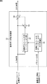
本発明によれば、第1の画像処理装置が提供される。この第1の画像処理装置(例えば図1の画像処理装置1、図12の画像処理装置101、または図13の画像処理装置102)は、所定の撮影装置により撮影された動画像を、アクセスユニットを単位として処理し、ホールド型表示素子に表示させる画像処理装置であって、前記動画像におけるアクセスユニットのレート(例えば、アクセスユニットとしてフレームが採用されている場合、フレームレート)を、前記撮影装置により前記動画像が撮影されたときのアクセスユニットのレートである第1のレートから、前記ホールド型表示素子を介して表示する際に生じるホールドボケを低減する程度に高レート化された第2のレートに変換する高レート変換処理を実行する高レート変換手段(例えば、図1、図12、または図13の高フレームレート変換部11)と、前記動画像を構成する複数のアクセスユニットのそれぞれについて、前記撮影装置により前記動画像が撮影されるときに発生する撮像ボケの特性を示すパラメータの値を1以上検出する検出手段(例えば、図1、図12、または図13の撮像ボケ特性検出部12)と、前記高レート変換手段による高レート変換処理が実行される前または後に、前記動画像を構成する複数の前記アクセスユニットのそれぞれについて、前記検出手段により検出された前記パラメータの値のうちの処理対象のアクセスユニットに対応する1以上の値に基づいて、処理対象の前記アクセスユニットを構成する各画素値を補正する補正手段(例えば、図1、図12、または図13の撮像ボケ抑制処理部13)とを備えることを特徴とする。
According to the present invention, a first image processing apparatus is provided. The first image processing apparatus (for example, the
この第1の画像処理装置において、前記補正手段(例えば、図5の撮像ボケ抑制処理部13)は、前記動画像を構成する複数の前記アクセスユニットのそれぞれについて、処理対象の前記アクセスユニットを構成する前記各画素のうちの処理対象として注目すべき画素を注目画素として設定し、前記検出手段により検出された1以上の前記パラメータの値のうちの前記注目画素に対応する値に応じて、前記撮像ボケを示すローパスフィルタの特性を変換する(例えば、パラメータの値として、移動速度2,3,4のそれぞれが検出された場合、ローパスフィルタの周波数特性を、図4の撮像ボケの周波数特性H2,H3,H4のそれぞれに変換する)フィルタ特性変換手段(例えば、図5の移動平均フィルタ(ローパスフィルタ)特性変換部21)と、前記フィルタ特性変換手段により特性が変換された前記ローパスフィルタの逆フィルタを生成する逆フィルタ生成手段(例えば、図5の逆移動平均フィルタ(ハイパスフィルタ)生成部22)と、処理対象の前記アクセスユニットのうちの前記注目画素を含む所定のブロックに対して、前記逆フィルタ生成手段により生成された前記逆フィルタをかけることで、前記注目画素の画素値を補正するフィルタリング手段(例えば、図5の逆移動平均フィルタ部(ハイパスフィルタ部)23)とを有するようにすることができる。
In the first image processing apparatus, the correction unit (for example, the imaging blur
この第1の画像処理装置において、前記補正手段(例えば、図6の撮像ボケ抑制処理部13)は、前記動画像を構成する複数の前記アクセスユニットのそれぞれについて、処理対象の前記アクセスユニットを構成する前記各画素のうちの処理対象として注目すべき画素を注目画素として設定し、前記検出手段により検出された1以上の前記パラメータの値のうちの前記注目画素に対応する値に応じて、前記撮像ボケを示すローパスフィルタの特性を変換するフィルタ特性変換手段(例えば、図6の移動平均フィルタ(ローパスフィルタ)特性変換部31)と、処理対象の前記アクセスユニットのうちの前記注目画素を含む所定のブロックに対して、前記フィルタ特性変換手段により特性が変換された前記ローパスフィルタをかけ、その結果得られる前記注目画素の補正された画素値を第1の値として出力するフィルタリング手段(例えば、図6の移動平均フィルタ部(ローパスフィルタ部)32)と、前記注目画素の補正前の画素値と、前記フィルタリング手段から出力された第1の値との差分を演算し、その結果得られる差分値を第2の値として出力する減算手段(例えば、図6の減算部33)と、前記減算手段から出力された前記第2の値を、前記注目画素の補正前の前記画素値に加算し、その結果得られる加算値を、前記注目画素の補正後の画素値として出力する加算手段(例えば、図6の加算部34)とを有するようにすることができる。
In the first image processing apparatus, the correction unit (for example, the imaging blur
この第1の画像処理装置において、前記補正手段(例えば、図7または図9の撮像ボケ抑制処理部13)は、前記動画像を構成する複数の前記アクセスユニットのそれぞれについて、処理対象の前記アクセスユニットを構成する前記各画素のうちの処理対象として注目すべき画素を注目画素として設定し、処理対象の前記アクセスユニットのうちの、前記注目画素を含む所定の方向に連続して並ぶ画素群に対応する第1の画像信号(例えば、図8の信号a)が順次入力され、入力された前記第1の画像信号を、N画素分(Nは1以上の整数値)に対応する第1の遅延時間(例えば、図8の時間T)だけ遅延させ、その結果得られる第2の画像信号(例えば、図8の信号b)を出力する第1の遅延手段(例えば、図7または図9の可変DL部52)と、第1の遅延手段から出力された前記第2の画像信号が順次入力され、入力された前記第2の画像信号を、M画素分(Mは、Nを含む1以上の整数値)に対応する第2の遅延時間(例えば、図8の時間T)だけ遅延させ、その結果得られる第3の画像信号(例えば、図8の信号c)を出力する第2の遅延手段(例えば、図7または図9の可変DL部53)と、前記第1の遅延手段に入力された前記第1の画像信号、前記第1の遅延手段から出力されて前記第2の遅延手段に入力された前記第2の画像信号、および、前記第2の遅延手段から出力された前記第3の画像信号を利用して、前記注目画素の画素値を補正する画素値補正手段(例えば、図7の補正部54−1または図9の補正部54−2)と、前記検出手段により検出された前記パラメータの値のうちの前記注目画素に対応する値に応じて、前記第1の遅延手段の前記第1の遅延時間を変更するとともに、前記第2の遅延手段の前記第2の遅延時間を変更する遅延時間変更手段(例えば、図7または図9の遅延時間変更部55)とを有するようにすることができる。
In the first image processing apparatus, the correction unit (for example, the imaging blur
本発明によれば、第1の画像処理方法が提供される。この第1の画像処理方法は、所定の撮影装置により撮影された動画像を、アクセスユニットを単位として処理し、ホールド型表示素子に表示させる画像処理装置(例えば図1の画像処理装置1、図12の画像処理装置101、または図13の画像処理装置102)の画像処理方法であって、前記動画像におけるアクセスユニットのレートを、前記撮影装置により前記動画像が撮影されたときのアクセスユニットのレートである第1のレートから、前記ホールド型表示素子を介して表示する際に生じるホールドボケを低減する程度に高レート化された第2のレートに変換する高レート変換処理を実行する高レート変換ステップ(例えば、図3のステップS2の処理)と、前記動画像を構成する複数のアクセスユニットのそれぞれについて、前記撮影装置により前記動画像が撮影されるときに発生する撮像ボケの特性を示すパラメータの値を1以上検出する検出ステップ(例えば、図3のステップS3の処理)と、前記高レート変換ステップによる高レート変換処理が実行される前または後に、前記動画像を構成する複数の前記アクセスユニットのそれぞれについて、前記検出ステップの処理により検出された前記パラメータの値のうちの処理対象のアクセスユニットに対応する1以上の値に基づいて、処理対象の前記アクセスユニットを構成する各画素値を補正する補正ステップ(例えば、図3のステップS4の処理。なお、図3の例では、高レート変換ステップによる高レート変換処理の例であるステップS2が実行された後に、補正ステップの例であるステップS4の処理が実行されているが、当然ながらステップS4の後にステップS2の処理を実行してもよく、このことについては後述する)とを含むことを特徴とする。
According to the present invention, a first image processing method is provided. In the first image processing method, an image processing apparatus (for example, the
この第1の画像処理方法において、前記補正ステップ(例えば、図5の撮像ボケ抑制処理部13の処理)は、前記動画像を構成する複数の前記アクセスユニットのそれぞれについて、処理対象の前記アクセスユニットを構成する前記各画素のうちの処理対象として注目すべき画素を注目画素として設定し、前記注目画素に対するステップとして、前記検出ステップの処理により検出された1以上の前記パラメータの値のうちの前記注目画素に対応する値に応じて、前記撮像ボケを示すローパスフィルタの特性を変換するフィルタ特性変換ステップ(例えば、図5の移動平均フィルタ(ローパスフィルタ)特性変換部21の処理)と、前記フィルタ特性変換ステップの処理により特性が変換された前記ローパスフィルタの逆フィルタを生成する逆フィルタ生成ステップ(例えば、図5の逆移動平均フィルタ(ハイパスフィルタ)生成部22の処理)と、処理対象の前記アクセスユニットのうちの前記注目画素を含む所定のブロックに対して、前記逆フィルタ生成ステップの処理により生成された前記逆フィルタをかけることで、前記注目画素の画素値を補正するフィルタリングステップ(例えば、図5の逆移動平均フィルタ部(ハイパスフィルタ部)23の処理)とを含むようにすることができる。
In the first image processing method, the correction step (for example, the processing of the imaging blur
この第1の画像処理方法において、前記補正ステップ(例えば、図6の撮像ボケ抑制処理部13の処理)は、前記動画像を構成する複数の前記アクセスユニットのそれぞれについて、処理対象の前記アクセスユニットを構成する前記各画素のうちの処理対象として注目すべき画素を注目画素として設定し、前記注目画素に対するステップとして、前記検出ステップの処理により検出された1以上の前記パラメータの値のうちの前記注目画素に対応する値に応じて、前記撮像ボケを示すローパスフィルタの特性を変換するフィルタ特性変換ステップ(例えば、図6の移動平均フィルタ(ローパスフィルタ)特性変換部31の処理)と、処理対象の前記アクセスユニットのうちの前記注目画素を含む所定のブロックに対して、前記フィルタ特性変換ステップの処理により特性が変換された前記ローパスフィルタをかけ、その結果得られる前記注目画素の補正された画素値を第1の値として出力するフィルタリングステップ(例えば、図6の移動平均フィルタ部(ローパスフィルタ部)32の処理)と、前記注目画素の補正前の画素値と、前記フィルタリングステップの処理結果として出力された前記第1の値との差分を演算し、その結果得られる差分値を第2の値として出力する減算ステップ(例えば、図6の減算部33の処理)と、前記減算ステップの処理結果として出力された前記第2の値を、前記注目画素の補正前の前記画素値に加算し、その結果得られる加算値を、前記注目画素の補正後の画素値として出力する加算ステップ(例えば、図6の加算部34の処理)とを含むことを特徴とする。
In the first image processing method, the correction step (for example, the processing of the imaging blur
この第1の画像処理方法において、前記補正ステップ(例えば、6または図9の撮像ボケ抑制処理部13の処理)は、前記動画像を構成する複数の前記アクセスユニットのそれぞれについて、処理対象の前記アクセスユニットを構成する前記各画素のうちの処理対象として注目すべき画素を注目画素として設定し、前記注目画素に対するステップとして、処理対象の前記アクセスユニットのうちの、前記注目画素を含む所定の方向に連続して並ぶ画素群に対応する第1の画像信号が順次入力され、入力された前記第1の画像信号を、N画素分(Nは1以上の整数値)に対応する第1の遅延時間だけ遅延させ、その結果得られる第2の画像信号を出力する第1の遅延ステップ(例えば、図7または図9の可変DL部52の処理)と、第1の遅延ステップの処理結果として出力された前記第2の画像信号が順次入力され、入力された前記第2の画像信号を、M画素分(Mは、Nを含む1以上の整数値)に対応する第2の遅延時間だけ遅延させ、その結果得られる第3の 画像信号を出力する第2の遅延ステップ(例えば、図7または図9の可変DL部53の処理)と、前記第1の遅延ステップの処理対象として入力された前記第1の画像信号、前記第1の遅延ステップの処理結果として出力されて前記第2の遅延ステップの処理対象として入力された前記第2の画像信号、および、前記第2の遅延ステップの処理結果として出力された前記第3の画像信号を利用して、前記注目画素の画素値を補正する画素値補正ステップ(例えば、図7の補正部54−1または図9の補正部54−2の処理)と、前記検出ステップの処理により検出された前記パラメータの値のうちの前記注目画素に対応する値に応じて、前記第1の遅延ステップの前記第1の遅延時間を変更するとともに、前記第2の遅延ステップの前記第2の遅延時間を変更する遅延時間変更ステップ(例えば、図7または図9の遅延時間変更部55の処理)とを含むようにすることができる。
In the first image processing method, the correction step (for example, the processing of the imaging blur
本発明によれば、第1の記録媒体が提供される。この第1の記録媒体(例えば、図16のリムーバブル記録媒体211や、記憶部208に含まれるハードディスク等)に記録されるプログラムは、所定の撮影装置により撮影された動画像に対して、アクセスユニットを単位として施す画像処理の制御を行うコンピュータ(例えば、図16の構成のコンピュータ)に実行させるプログラムであって、上述した本発明の第1の画像処理方法に対応するプログラムである。
According to the present invention, a first recording medium is provided. A program recorded on the first recording medium (for example, the
本発明によれば、第1のプログラムが提供される。この第1のプログラムは、上述した本発明の第1の記録媒体に記録されるプログラムに対応するプログラムである。 According to the present invention, a first program is provided. This 1st program is a program corresponding to the program recorded on the 1st recording medium of the present invention mentioned above.
本発明によれば、第2の画像処理装置が提供される。この第2の画像処理装置(例えば、13の画像処理装置112、または図15の画像処理装置131)は、所定の撮影装置により撮影された動画像と、前記動画像を構成する複数のアクセスユニットのそれぞれについての、前記撮影装置により前記動画像が撮影されるときに発生する撮像ボケの特性を示す1以上のパラメータの値とが他の画像処理装置(例えば、図14または図15の画像信号生成装置111)から供給されてきた場合、その動画像に対して処理し、ホールド型表示素子に表示させる画像処理装置であって、前記他の画像処理装置から供給された前記動画像におけるアクセスユニットのレートを、前記撮影装置により前記動画像が撮影されたときのアクセスユニットのレートである第1のレートから、前記ホールド型表示素子を介して表示する際に生じるホールドボケを低減する程度に高レート化された第2のレートに変換する高レート変換処理を実行する高レート変換手段(例えば、図14または図15の高フレームレート変換部11)と、前記高レート変換手段による高レート変換処理が実行される前または後に、前記他の画像処理装置から供給された前記動画像を構成する複数の前記アクセスユニットのそれぞれについて、前記他の画像処理装置から供給された前記パラメータの値のうちの処理対象のアクセスユニットに対応する1以上の値に基づいて、処理対象の前記アクセスユニットを構成する各画素値を補正する補正手段(例えば、図14または図15の撮像ボケ抑制処理部13)とを備えることを特徴とする。
According to the present invention, a second image processing apparatus is provided. The second image processing device (for example, the 13
本発明によれば、第2の画像処理方法が提供される。この第2の画像処理方法は、所定の撮影装置により撮影された動画像と、前記動画像を構成する複数のアクセスユニットのそれぞれについての、前記撮影装置により前記動画像が撮影されるときに発生する撮像ボケの特性を示す1以上のパラメータの値とが他の画像処理装置(例えば、図14または図15の画像信号生成装置111)から供給されてきた場合、その動画像に対して処理し、ホールド型表示素子に表示させる画像処理装置(例えば、13の画像処理装置112、または図15の画像処理装置131)の画像処理方法であって、前記他の画像処理装置から供給された前記動画像におけるアクセスユニットのレートを、前記撮影装置により前記動画像が撮影されたときのアクセスユニットのレートである第1のレートから、前記ホールド型表示素子を介して表示する際に生じるホールドボケを低減する程度に高レート化された第2のレートに変換する高レート変換処理を実行する高レート変換ステップ(例えば、図3のステップS2の処理)と、前記高レート変換ステップによる高レート変換処理が実行される前または後に、前記他の画像処理装置から供給された前記動画像を構成する複数の前記アクセスユニットのそれぞれについて、前記他の画像処理装置から供給された前記パラメータの値のうちの処理対象のアクセスユニットに対応する1以上の値に基づいて、処理対象の前記アクセスユニットを構成する各画素値を補正する補正ステップ(例えば、図3のステップS4の処理)とを含むことを特徴とする。
According to the present invention, a second image processing method is provided. This second image processing method occurs when the moving image is shot by the shooting device for each of the moving image shot by a predetermined shooting device and the plurality of access units constituting the moving image. If the value of one or more parameters indicating the characteristic of the imaging blur is supplied from the other image processing apparatus (e.g., an image
なお、図3の例では、高レート変換ステップによる高レート変換処理の例であるステップS2が実行された後に、補正ステップの例であるステップS4の処理が実行されているが、当然ながらステップS4の後にステップS2の処理を実行してもよく、このことについては後述する。また、第2の画像処理方法においては、図3のステップS3の処理は省略される。このことについても後述する。 In the example of FIG. 3, the process of step S4, which is an example of the correction step, is executed after step S2, which is an example of the high rate conversion process by the high rate conversion step, is executed. After this, step S2 may be performed, which will be described later. Further, in the second image processing method, the process of step S3 in FIG. 3 is omitted. This will also be described later.
本発明によれば、第2の記録媒体が提供される。この第2の記録媒体(例えば、図16のリムーバブル記録媒体211や、記憶部208に含まれるハードディスク等)に記録されるプログラムは、所定の撮影装置により撮影された動画像と、動画像を構成する複数のアクセスユニットのそれぞれについての、撮影装置により動画像が撮影されるときに発生する撮像ボケの特性を示す1以上のパラメータの値とが与えられた場合、その動画像に対する画像処理の制御を行うコンピュータ(例えば、図16の構成のコンピュータ)に実行させるプログラムであって、上述した本発明の第2の画像処理方法に対応するプログラムである。
According to the present invention, a second recording medium is provided. A program recorded on the second recording medium (for example, the
本発明によれば、第2のプログラムが提供される。この第2のプログラムは、上述した本発明の第2の記録媒体に記録されるプログラムに対応するプログラムである。 According to the present invention, a second program is provided. This second program is a program corresponding to the program recorded on the second recording medium of the present invention described above.
以上説明した本発明の第1および第2の画像処理装置は、例えば、テレビジョンシステム全体またはその一構成要素として利用可能である。テレビジョンシステムとは、テレビジョン放送受像機を含む1以上のAV(Audio and Visual)機器からなるシステムを指す。 The first and second image processing apparatuses of the present invention described above can be used as, for example, the entire television system or one component thereof. The television system refers to a system composed of one or more AV (Audio and Visual) devices including a television broadcast receiver.
次に、図面を参照して、本発明の実施の形態について説明する。 Next, embodiments of the present invention will be described with reference to the drawings.
図1は、本発明が適用される画像処理装置の機能的構成の一例を示している。 FIG. 1 shows an example of the functional configuration of an image processing apparatus to which the present invention is applied.
この画像処理装置1は、動画像データに対する各種画像処理をアクセスユニット単位で実行する。アクセスユニットとは、フレームやフィールドといった動画像の単位を指し、具体的には例えば、動画像を構成する各コマ(静止画像)全体またはその一部分を指す。ただし、以下、説明の簡略上、画像処理装置1は、動画像データに対する各種画像処理をフレーム単位で実行するとする。
The
この画像処理装置1は、図1に示されるように、高フレームレート変換部11、撮像ボケ特性検出部12、および、撮像ボケ抑制処理部13から構成される。
As shown in FIG. 1, the
高フレームレート変換部11には、例えば、テレビジョン放送信号等の動画像信号が、フレーム単位の動画像データとして入力される。
For example, a moving image signal such as a television broadcast signal is input to the high frame
なお、以下、動画像と、それに対応する動画像データとを個々に区別する必要がない場合、これらをまとめて動画像と単に称する。同様に、フレームと、それに対応するフレームデータとを個々に区別する必要がない場合、これらをまとめてフレームと単に称する。 Hereinafter, when it is not necessary to individually distinguish a moving image and corresponding moving image data, these are simply referred to as a moving image. Similarly, when it is not necessary to distinguish between a frame and the corresponding frame data, these are collectively referred to simply as a frame.
高フレームレート変換部11は、第1のフレームレートの動画像が入力された場合、その動画像に対して高フレームレート変換処理を施し、その結果得られる、第1のフレームレートよりも高い第2のフレームレートの動画像を撮像ボケ特性検出部12と撮像ボケ抑制処理部13に供給する。
When a moving image having the first frame rate is input, the high frame
高フレームレート変換処理とは、入力時の第1のフレームレートが出力(表示)時の第2のフレームレートよりも低い場合に実行される処理であって、入力時の動画像を構成する各フレームのそれぞれの間に、新たなフレームを創造してそれぞれ挿入することで、第1のフレームレートをそれよりも高い第2のフレームレートに変換する処理を指す。 The high frame rate conversion process is a process that is executed when the first frame rate at the time of input is lower than the second frame rate at the time of output (display). This refers to a process of converting a first frame rate to a higher second frame rate by creating and inserting new frames between the frames.
なお、第1のフレームレートとは、高フレームレート変換部11に入力された時点の動画像のフレームレートを指す。従って、第1のフレームレートは、任意のフレームレートとなり得るが、ここでは例えば、図示せぬ撮影装置により動画像が撮影されたときのフレームレート、即ち、撮像フレームレートであるとする。
Note that the first frame rate refers to the frame rate of the moving image at the time of input to the high frame
撮像ボケ特性検出部12は、高フレームレート変換部11から供給された動画像を構成する各フレームのそれぞれについて、撮像ボケの特性を示すパラメータの値を検出する。撮像ボケ特性検出部12の検出結果、即ち、撮像ボケの特性を示すパラメータの値は、撮像ボケ抑制処理部13に供給される。
The imaging blur
なお、撮像ボケの特性を示すパラメータは、特に限定されず様々なパラメータの採用が可能である。ただし、撮像ボケの特性を示すパラメータの具体例については後述する。 Note that parameters indicating the characteristics of imaging blur are not particularly limited, and various parameters can be employed. However, specific examples of parameters indicating the characteristics of imaging blur will be described later.
また、1つのフレーム内での、撮像ボケの特性を示すパラメータの値の検出個数も特に限定されない。例えば、1つのフレームに対して、撮像ボケの特性を示すパラメータの値が1つのみ検出されてもよいし、そのフレームを構成する各画素毎に、撮像ボケの特性を示すパラメータの値が1つずつ個別に検出されてもよい。或いは、その1つのフレームが幾つかのブロックに分割され、分割された各ブロック毎に、撮像ボケの特性を示すパラメータの値が1つずつ個別に検出されてもよい。 Also, the number of detected parameter values indicating the characteristics of imaging blur within one frame is not particularly limited. For example, only one parameter value indicating the imaging blur characteristic may be detected for one frame, or the parameter value indicating the imaging blur characteristic is 1 for each pixel constituting the frame. Each may be detected individually. Alternatively, the one frame may be divided into several blocks, and the parameter value indicating the imaging blur characteristic may be individually detected for each of the divided blocks.
撮像ボケ抑制処理部13は、高フレームレート変換部11から供給された動画像を構成する各フレームのそれぞれについて、撮像ボケ特性検出部12により検出されたパラメータの値のうちの処理対象のフレームに対応する値に基づいて、処理対象のフレームを構成する各画素値を補正する。即ち、撮像ボケ抑制処理部13は、処理対象のフレームについての撮像ボケの特性(パラメータの値)に応じて、処理対象のフレームの各画素値を、その撮像ボケが抑制されるように補正する。
The imaging blur
これにより、各フレームの各画素値が補正されることで撮像ボケが抑制された動画像であって、入力時の第1のフレームレートよりも高い第2のフレームレートに変換された動画像が、撮像ボケ抑制処理部13から画像処理装置1の外部に出力される。
Thereby, a moving image in which imaging blur is suppressed by correcting each pixel value of each frame, and the moving image is converted to a second frame rate higher than the first frame rate at the time of input. The image blur
なお、図1の例では、撮像ボケ特性検出部12と撮像ボケ抑制処理部13との組は、高フレームレート変換部11と組み合わせて用いられているが、当然ながら、その組単体で用いることも可能であるし、また、図示せぬ他のブロック(所定の画像処理を施す他の画像処理部)と組み合わせて用いることも可能である。
In the example of FIG. 1, the set of the imaging blur
即ち、撮像ボケ特性検出部12と撮像ボケ抑制処理部13との組だけで、撮像ボケを抑制するという効果を奏することが可能になる。ただし、この効果をより顕著にするためには、撮像ボケ特性検出部12と撮像ボケ抑制処理部13との組に対して、上述したように、高フレームレート変換部11を組み合わせると好適である。以下、この理由について説明していく。
That is, only the combination of the imaging blur
図示せぬ表示装置に表示される動画像が人間の網膜上に像として形成される際にその人間に認識されるボケは、その人間が動画像に含まれる動物体を追従視することによるホールドボケと、その動画像の撮像時に加わる上述した撮像ボケとを組み合わせたものである。 When a moving image displayed on a display device (not shown) is formed as an image on the human retina, the blur recognized by the human is held by the human following the moving object included in the moving image. This is a combination of the blur and the above-described imaging blur applied at the time of capturing the moving image.
ここでいう撮像ボケの特性は、図4等を参照して後述するように、ローパスフィルタとして表される。即ち、撮像ボケ後の画像信号とは、撮像ボケ前の画像信号(理想的な画像信号)に対してこのローパスフィルタがかけられた信号と等価な信号である。従って、撮像ボケ後の画像信号は、撮像ボケ前の画像信号と比較して、その周波数特性が落ちてしまう。即ち、撮像ボケ後の画像信号においては、撮像ボケ前の画像信号と比較して、高周波数になればなる程ゲインが一般的に落ちてしまう。 The characteristic of imaging blur here is represented as a low-pass filter, as will be described later with reference to FIG. That is, the image signal after imaging blur is a signal equivalent to a signal obtained by applying this low-pass filter to the image signal (ideal image signal) before imaging blur. Therefore, the frequency characteristic of the image signal after the imaging blur is deteriorated as compared with the image signal before the imaging blur. That is, in the image signal after the imaging blur, the gain generally decreases as the frequency becomes higher than the image signal before the imaging blur.
ここでいうホールドボケの特性もまた、撮像ボケの特性と同様にローパスフィルタとして表される。即ち、ホールドボケ後の画像信号とは、ホールドボケ前の画像信号(撮像ボケ後の画像信号)に対してこのローパスフィルタがかけられた信号と等価な信号である。従って、ホールドボケ後の画像信号は、ホールドボケ前の画像信号と比較して、その周波数特性が落ちてしまう。即ち、ホールドボケ後の画像信号においては、ホールドボケ前の画像信号と比較して、高周波数になればなる程ゲインが一般的に落ちてしまう。ただし、ホールドボケは、表示装置が固定画素(ホールド)表示装置の時にのみ発生する。 The hold blur characteristic here is also expressed as a low-pass filter in the same manner as the imaging blur characteristic. That is, the image signal after hold blur is a signal equivalent to a signal obtained by applying this low-pass filter to the image signal before hold blur (image signal after imaging blur). Therefore, the frequency characteristic of the image signal after hold blur is deteriorated as compared with the image signal before hold blur. That is, in the image signal after hold blur, the gain generally decreases as the frequency becomes higher than the image signal before hold blur. However, the hold blur occurs only when the display device is a fixed pixel (hold) display device.
従って、周波数特性が撮像ボケのため既に落ちている撮像ボケ後の画像信号に対して、高フレームレート変換処理を施すことで、ホールドボケを抑制すること自体は可能である。しかしながら、このような高フレームレート変換処理を施したとしても、撮像ボケの劣化は変わらず、最終的に人間の網膜上におけるボケを抑制させるという効果は半減してしまう。このことを、図2を参照して説明する。 Therefore, hold blur can be suppressed by performing high frame rate conversion processing on an image signal after imaging blur that has already fallen due to imaging blur. However, even if such a high frame rate conversion process is performed, the degradation of imaging blur does not change, and the effect of finally suppressing blur on the human retina is halved. This will be described with reference to FIG.
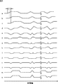
図2は、撮影装置(以下、カメラと称する)の撮影範囲内で移動速度4[画素/フレーム]で移動している実物体を撮影した時における、人間の網膜上で形成される像のボケの周波数特性を示している。図2において、横軸は周波数を、縦軸はゲインのそれぞれを示している。ただし、横軸の各値は、ナイキスト周波数が1とされた場合の相対値を示している。 FIG. 2 shows blurring of an image formed on a human retina when a real object moving at a moving speed of 4 [pixel / frame] within a shooting range of a shooting apparatus (hereinafter referred to as a camera) is shot. The frequency characteristics are shown. In FIG. 2, the horizontal axis represents frequency, and the vertical axis represents gain. However, each value on the horizontal axis represents a relative value when the Nyquist frequency is 1.
図2において、同図中一点鎖線で示される曲線h0は、ボケ(撮像ボケもホールドボケも含む)を改善するための処理が特に施されていない場合における、人間の網膜上で形成される像のボケの周波数特性を示している。即ち、図1の例では画像処理装置1に入力される動画像が、仮に画像処理装置1に入力されること無く(処理されること無く)そのまま表示装置に供給されて表示された場合に、人間がその動画像を見たときに網膜上で形成される像のボケの周波数特性が、曲線h0である。
In FIG. 2, a curve h0 indicated by an alternate long and short dash line in FIG. 2 represents an image formed on the human retina when no process for improving blur (including imaging blur and hold blur) is performed. This shows the frequency characteristics of the blur. That is, in the example of FIG. 1, when a moving image input to the
これに対して、例えば高フレームレート変換処理により表示速度が倍にされると、ホールドボケのみは改善され、その結果、人間の網膜上で形成される像のボケの周波数特性は、同図中点線で示される曲線h1になる。即ち、図1の画像処理装置1に入力された動画像が、高フレームレート変換部11により高フレームレート変換処理が施され、その後、仮に撮像ボケ抑制処理部13に入力されること無く(撮像ボケが改善されること無く)表示装置に供給されて表示された場合、人間がその動画像を見たときに網膜上で形成される像のボケの周波数特性が、曲線h1である。
On the other hand, for example, when the display speed is doubled by high frame rate conversion processing, only the hold blur is improved. As a result, the frequency characteristics of the blur of the image formed on the human retina are shown in FIG. It becomes a curve h1 indicated by a dotted line. That is, the moving image input to the
また、例えば本発明が適用されて、高フレームレート変換処理により表示速度が倍にされ(ホールドボケが改善され)、かつ撮像ボケの度合いが半分に改善されると、人間の網膜上で形成される像のボケの周波数特性は、同図中実線で示される曲線h2になる。即ち、図1の画像処理装置1に入力された動画像が、高フレームレート変換部11により高フレームレート変換処理が施され、さらに、撮像ボケ抑制処理部13により撮像ボケが抑制された上で表示装置に供給されて表示された場合、人間がその動画像を見たときに網膜上で形成される像のボケの周波数特性が、曲線h2である。
Further, for example, when the present invention is applied, the display speed is doubled by high frame rate conversion processing (hold blur is improved), and the degree of imaging blur is improved by half, the image is formed on the human retina. The frequency characteristic of the blur of the image becomes a curve h2 indicated by a solid line in FIG. That is, the moving image input to the
曲線h1と曲線h2とを比較するに、高フレームレート変換処理によりホールドボケのみが改善されただけでは、人間の網膜上におけるボケの特性の改善は不十分であり、さらに撮像ボケの改善も必要なことがわかる。しかしながら、上述したように、従来の手法では、撮像ボケの改善が必要なことは特に考慮されずに、高フレームレート変換処理が単に行われていた。 When comparing curve h1 and curve h2, only improvement of hold blur by high frame rate conversion processing is insufficient to improve the blur characteristics on the human retina, and it is also necessary to improve imaging blur I understand that. However, as described above, in the conventional method, the high frame rate conversion processing is simply performed without particularly considering that the improvement in imaging blur is necessary.
そこで、図1の実施例の他、後述する図12や図13等の実施例で示される本発明の画像処理装置においては、高フレームレート変換部11の他さらに、撮像ボケの改善を目的として、即ち、人間の網膜上のけるボケの特性を図2の曲線h0から曲線h2のように改善することを目的として、撮像ボケ特性検出部12と撮像ボケ抑制処理部13とが設けられているのである。ただし、後述する図14と図15の実施例で示されるように、撮像ボケ特性検出部12は、本発明の画像処理装置にとって必須な構成要素ではない。
Therefore, in addition to the embodiment of FIG. 1, in the image processing apparatus of the present invention shown in the embodiments of FIG. 12 and FIG. 13, which will be described later, in addition to the high frame
即ち、撮像ボケ抑制処理部13は、各フレームのそれぞれについて、撮像ボケ特性検出部12により検出された撮像ボケの特性を示すパラメータの値のうちの処理対象のフレームに対応する値に基づいて、処理対象のフレームの各画素値を補正することで、高フレームレート変換後のフレームについての撮像ボケに起因する画像劣化を抑制しているのである。即ち、画像処理装置1など、本発明の画像処理装置から出力された画像信号を図示せぬ表示装置に供給することで、表示装置は、その画像信号に対応する映像として、画像劣化(ボケ画像)が抑制された鮮明な映像を表示することが可能になるのである。
That is, for each frame, the imaging blur
このように、撮像ボケ特性検出部12と撮像ボケ抑制処理部13との組は、高フレームレート変換部11と組み合わされると好適である。
As described above, the combination of the imaging blur
次に、図3のフローチャートを参照して、かかる図1の機能的構成を有する画像処理装置1の画像処理について説明する。
Next, image processing of the
ステップS1において、高フレームレート変換部11は、第1のフレームレートの動画像を入力する。
In step S1, the high frame
ステップS2において、高フレームレート変換部11は、動画像のフレームレートを、第1のフレームレートよりも高い第2のフレームレートに変換する。
In step S <b> 2, the high frame
第1のフレームレートから第2のフレームレートに変換された動画像が、高フレームレート変換部11から撮像ボケ特性検出部12と撮像ボケ抑制処理部13とに供給されると、処理はステップS3に進む。
When the moving image converted from the first frame rate to the second frame rate is supplied from the high frame
ステップS3において、撮像ボケ特性検出部12は、動画像を構成する各フレームのそれぞれの中から、撮像ボケの特性を示すパラメータの値を1以上検出する。
In step S <b> 3, the imaging blur
動画像を構成する各フレームのそれぞれについての撮像ボケの特性を示すパラメータの1以上の値が、撮像ボケ特性検出部12から撮像ボケ抑制処理部13に供給されると、処理はステップS4に進む。
When one or more values of parameters indicating the characteristics of imaging blur for each frame constituting the moving image are supplied from the imaging blur
ステップS4において、撮像ボケ抑制処理部13は、高フレームレート変換部11から供給された動画像を構成する各フレームのそれぞれについて、撮像ボケ特性検出部12により検出されたパラメータの値のうちの処理対象のフレームに対応する1以上の値に基づいて、処理対象のフレームの各画素値を補正する。
In step S <b> 4, the imaging blur
ステップS5において、撮像ボケ抑制処理部13は、各フレームの画素値が補正され、かつ、第1のフレームレートから第2のフレームレートに変更された動画像を出力する。
In step S5, the imaging blur
これにより、図3の画像処理は終了となる。 Thereby, the image processing of FIG. 3 is completed.
なお、上述した説明では、説明の簡略上、ステップS1乃至S5の各ステップの処理は、動画像が処理単位とされた。ただし、実際には、フレームが処理単位となる場合が多々ある。 In the above description, for the sake of simplicity, the processing of each step of steps S1 to S5 is a moving image as a processing unit. In practice, however, there are many cases where a frame is a processing unit.
図3の画像処理において、各ステップの処理単位が動画像であるとは、ステップS1乃至S5のうちの処理対象のステップから次のステップへの移行条件が、処理対象のステップの処理が動画像全体に対して施されるという条件になることと等価である。 In the image processing of FIG. 3, the processing unit of each step is a moving image. The transition condition from the processing target step in steps S1 to S5 to the next step is that the processing of the processing target step is a moving image. Equivalent to being applied to the whole.
これに対して、図3の画像処理において、各ステップの処理単位がフレームであるとは、ステップS1乃至S5のうちの処理対象のステップから次のステップへの移行条件が、処理対象のステップの処理が1つのフレーム全体に対して施されるという条件になることと等価である。換言すると、各ステップの処理単位がフレームであるとは、各フレームのそれぞれに対するステップS1乃至S5の連続処理が、他のフレームとは独立して(並行して)実行されることと等価である。この場合、例えば、第1のフレームに対するステップS3の処理が実行されているときに、それとは異なる第2のフレームに対するステップS2の処理が並行して実行されているようなことが起こり得る。 On the other hand, in the image processing of FIG. 3, that the processing unit of each step is a frame, the transition condition from the processing target step of steps S1 to S5 to the next step is that of the processing target step. This is equivalent to the condition that the processing is performed on the entire frame. In other words, the processing unit of each step is a frame is equivalent to the continuous processing of steps S1 to S5 for each frame being executed independently (in parallel) with other frames. . In this case, for example, when the process of step S3 for the first frame is being executed, the process of step S2 for a different second frame may be executed in parallel.
さらに、実際には、処理対象のフレームを構成する各画素のそれぞれが、処理の対象として注目すべき画素(以下、注目画素と称する)に順次設定されて、その注目画素に対して、少なくともステップS3とS4の処理が順次個別に施されていくことが多々ある。即ち、ステップS3とS4の処理単位は画素であることが多々ある。 Further, in practice, each pixel constituting the processing target frame is sequentially set as a pixel to be noted as a processing target (hereinafter referred to as a target pixel), and at least a step is performed on the target pixel. In many cases, the processes of S3 and S4 are sequentially performed individually. That is, the processing unit of steps S3 and S4 is often a pixel.
そこで、以下の説明においても、ステップS3とS4の処理は画素単位であるとして説明していく。即ち、ステップS3の処理とは撮像ボケ特性検出部12の処理であり、ステップS4の処理とは撮像ボケ抑制処理部13の処理である。従って、以下の説明においては、撮像ボケ特性検出部12と撮像ボケ抑制処理部13の処理単位は画素であるとして説明していく。
Therefore, in the following description, the processing in steps S3 and S4 will be described on a pixel basis. That is, the process of step S3 is the process of the imaging blur
次に、図1の画像処理装置1のうちの、撮像ボケ抑制処理部13の幾つかの実施の形態例について説明していく。具体的には例えば、撮像ボケの特性を示すパラメータとして、移動ベクトルの絶対値(以下、移動速度と称する)を利用する場合の撮像ボケ抑制処理部13の幾つかの実施の形態例について説明していく。
Next, some embodiments of the imaging blur
撮像ボケの特性を示すパラメータとして移動速度が利用される場合、撮像ボケ特性検出部12は、例えば、動画像を構成する各フレームのそれぞれについて、処理対象のフレームを構成する各画素のそれぞれを注目画素として順次設定し、注目画素における移動ベクトルを順次検出し、それを、注目画素における撮像ボケの特性を示すパラメータの値として撮像ボケ抑制処理部13に順次供給していくことになる。
When the moving speed is used as a parameter indicating the characteristics of the imaging blur, the imaging blur
従って、撮像ボケ抑制処理部13は、例えば、動画像を構成する各フレームのそれぞれについて、処理対象のフレームを構成する各画素のそれぞれを注目画素として順次設定し、撮像ボケ特性検出部12から供給された移動ベクトルのうちの注目画素における移動ベクトルの絶対値に基づいて、即ち、注目画素における移動速度に基づいて、注目画素の画素値を順次補正していくことになる。
Therefore, the imaging blur
ここで、移動速度が、撮像ボケの特性を示すパラメータとして採用可能な理由について説明する。 Here, the reason why the moving speed can be adopted as a parameter indicating the characteristics of imaging blur will be described.
撮像ボケの特性は、一般的に被写体の移動速度に依存した形態で表すことが可能である。 The characteristics of imaging blur can be generally expressed in a form depending on the moving speed of the subject.
なお、被写体の移動速度とは、実空間において被写体自体が移動してカメラが固定されている場合に、その被写体がカメラで撮影されたときの、フレーム内での被写体(画像)の移動速度を当然ながら含む。さらに、ここで言う被写体の移動速度とは、実空間において被写体が固定されてカメラが手振れ等により移動した場合、または、実空間において被写体とカメラとが共に移動した場合に、その被写体がカメラで撮影されたときの、フレーム内での被写体(画像)の相対的な移動速度も含む。 The moving speed of the subject is the moving speed of the subject (image) within the frame when the subject is moved in real space and the camera is fixed. Of course included. Furthermore, the moving speed of the subject referred to here means that the subject is a camera when the subject is fixed in real space and the camera moves due to camera shake or when the subject and the camera move together in real space. It also includes the relative moving speed of the subject (image) within the frame when the image is taken.
従って、撮像ボケの特性は、被写体の画像を構成する各画素における移動速度に依存した形態で表すことができる。 Therefore, the characteristics of the imaging blur can be expressed in a form depending on the moving speed of each pixel constituting the subject image.
画素における移動速度とは、処理対象のフレーム内の画素と、それよりも前のフレーム内の対応する画素(対応点)との間の空間的な距離を指す。例えば、処理対象のフレーム内の画素と、その直前(時間的に1つ前)のフレーム内の対応する画素(対応点)との間の空間的な距離が、K(Kは、0以上の任意の整数値)画素分である場合、その画素における移動速度とは、K[画素/フレーム]になる。 The moving speed of a pixel refers to a spatial distance between a pixel in a frame to be processed and a corresponding pixel (corresponding point) in a previous frame. For example, the spatial distance between the pixel in the processing target frame and the corresponding pixel (corresponding point) in the immediately preceding frame (temporarily before) is K (K is 0 or more). In the case of an arbitrary integer value) pixel, the moving speed of the pixel is K [pixel / frame].
この場合、被写体の画像を構成する各画素のうちの所定の1つが注目画素に設定されているとすると、注目画素における撮像ボケの特性は、注目画素における移動速度K[画素/フレーム]の大小に依存した形態で表すことができる。 In this case, assuming that a predetermined one of the pixels constituting the image of the subject is set as the target pixel, the characteristic of the imaging blur at the target pixel is the magnitude of the moving speed K [pixel / frame] at the target pixel. It can be expressed in a form dependent on
より具体的には例えば、注目画素の移動速度が2,3,4[画素/フレーム]のそれぞれの場合、注目画素における撮像ボケの周波数特性のそれぞれは、図4の曲線H2乃至H4のそれぞれで表すことができる。 More specifically, for example, when the moving speed of the target pixel is 2, 3, and 4 [pixel / frame], the frequency characteristics of the imaging blur at the target pixel are the curves H2 to H4 in FIG. Can be represented.
即ち、図4は、注目画素における移動速度が2,3,4[画素/フレーム]のそれぞれの場合についての、注目画素における撮像ボケの周波数特性のそれぞれを示している。図4において、横軸は周波数を、縦軸はゲインのそれぞれを示している。ただし、横軸の各値は、ナイキスト周波数が1とされた場合の相対値を示している。 That is, FIG. 4 shows each of the frequency characteristics of the imaging blur at the target pixel when the moving speed at the target pixel is 2, 3, and 4 [pixel / frame]. In FIG. 4, the horizontal axis represents frequency, and the vertical axis represents gain. However, each value on the horizontal axis represents a relative value when the Nyquist frequency is 1.
以上の内容が、移動速度が、撮像ボケの特性を示すパラメータとして採用可能な理由である。 The above content is the reason why the moving speed can be adopted as a parameter indicating the characteristics of imaging blur.
ところで、図4の周波数特性H2乃至H4の形態からわかるように、注目画素における撮像ボケの特性は空間領域で表現すると、移動平均フィルタ(ローパスフィルタ)で表すことが可能である。 By the way, as can be seen from the forms of the frequency characteristics H2 to H4 in FIG. 4, the characteristics of the imaging blur at the target pixel can be expressed by a moving average filter (low-pass filter) in the spatial domain.
即ち、この移動平均フィルタ(ローパスフィルタ)を示す伝達関数(以下、撮像ボケの伝達関数と称する)をHと記述し、撮像ボケが仮に発生しなかった場合の理想的な画像信号(以下、撮像ボケ前の信号と称する)を周波数領域でFと記述し、かつ、カメラから出力される実際の画像信号、即ち、撮像ボケが発生した画像信号(以下、撮像ボケ後の信号と称する)を周波数領域でGと記述すると、撮像ボケ後の信号Gは、次の式(1)のように表される。 That is, a transfer function indicating the moving average filter (low-pass filter) (hereinafter referred to as a transfer function of imaging blur) is described as H, and an ideal image signal (hereinafter referred to as imaging) when no imaging blur occurs. (Referred to as the signal before blurring) is described as F in the frequency domain, and the actual image signal output from the camera, that is, the image signal generated by the imaging blur (hereinafter referred to as the signal after blurring) is the frequency. If G is described in the region, the signal G after the imaging blur is expressed as the following equation (1).
G = H×F ・・・(1) G = H x F (1)
本発明においては撮像ボケを取り除く(抑制する)ことが目的とされているので、この本発明の目的を達成するためには、既知である撮像ボケ後の信号Gと、既知である撮像ボケの伝達関数Hとから、撮像ボケ前の信号Fを予測演算すればよい。即ち、次の式(2)の予測演算が実行されればよい。 The purpose of the present invention is to remove (suppress) the imaging blur. In order to achieve the object of the present invention, the signal G after the known imaging blur and the known imaging blur are detected. From the transfer function H, the signal F before imaging blur may be predicted and calculated. That is, the prediction calculation of the following equation (2) may be executed.
F = inv(H)×G ・・・(2) F = inv (H) x G (2)
式(2)において、inv(H)は、撮像ボケの伝達関数Hの逆関数を示している。上述したように撮像ボケの伝達関数Hがローパスフィルタの特性を持つことから、その逆関数inv(H)も、当然ながらハイパスフィルタの特性を持つ。 In equation (2), inv (H) represents the inverse function of the transfer function H of imaging blur. As described above, since the transfer function H of the imaging blur has the characteristics of a low-pass filter, the inverse function inv (H) naturally has the characteristics of a high-pass filter.
また、上述したように、撮像ボケの伝達関数Hは、移動速度に応じてその特性が変化する。具体的には例えば、注目画素における移動速度が2,3,4[画素/フレーム]のそれぞれの場合、注目画素における撮像ボケの伝達関数Hの周波数特性は、図4の曲線H2,曲線H3,曲線H4のそれぞれに示されるような相異な特性となる。 As described above, the characteristic of the transfer function H of the imaging blur changes according to the moving speed. Specifically, for example, when the moving speed of the pixel of interest is 2, 3, and 4 [pixel / frame], the frequency characteristics of the transfer function H of the imaging blur at the pixel of interest are the curve H2, the curve H3, and the curve H3 of FIG. The characteristic is different as shown in each of the curves H4.
従って、撮像ボケ抑制処理部13は、移動速度に応じて撮像ボケの伝達関数Hの特性を変更して、特性が変更された伝達関数Hの逆関数inv(H)を求め、その逆関数inv(H)を用いて上述した式(2)の演算処理を実行すれば、本発明の目的、即ち、撮像ボケを取り除く(抑制する)という目的を達成することが可能になる。
Accordingly, the imaging blur
或いは、上述した式(2)の演算は周波数領域の演算であるので、本発明の目的を達成するために、撮像ボケ抑制処理部13は、上述した式(2)の演算処理と等価な空間領域での処理を実行してもよい。具体的には例えば、撮像ボケ抑制処理部13は、次のような第1乃至第3の処理を実行してもよい。
Alternatively, since the calculation of Expression (2) described above is a calculation in the frequency domain, in order to achieve the object of the present invention, the imaging blur
第1の処理とは、撮像ボケ特性検出部12から供給された注目画素における移動速度に応じて、注目画素における撮像ボケを示す移動平均フィルタ(ローパスフィルタ)の特性を変換する処理である。具体的には例えば、複数の移動速度毎に移動平均フィルタを1つずつ予め用意しておき、複数の移動平均フィルタの中から、注目画素における移動速度に対応する1つを選択する処理が、第1の処理の一例である。
The first process is a process of converting the characteristics of a moving average filter (low-pass filter) indicating the imaging blur at the target pixel according to the moving speed at the target pixel supplied from the imaging blur
第2の処理とは、次の第2−1乃至第2−3の処理からなる処理である。 The second process is a process composed of the following processes 2-1 to 2-3.
第2−1の処理とは、第1の処理により特性が変換された移動平均フィルタに対してフーリエ変換を施すことにより、その移動平均フィルタを周波数表示する処理である。具体的には例えば、注目画素における移動速度が2,3,4[画素/フレーム]のそれぞれの場合、図4の曲線H2,曲線H3,曲線H4のそれぞれを得る処理が第2−1の処理である。即ち、周波数領域で考えると、注目画素における撮像ボケの伝達関数Hを求める処理が第2−1の処理である。 The 2-1 process is a process for displaying the frequency of the moving average filter by performing Fourier transform on the moving average filter whose characteristics are converted by the first process. Specifically, for example, when the moving speed of the target pixel is 2, 3, and 4 [pixel / frame], the process of obtaining each of the curve H2, the curve H3, and the curve H4 in FIG. It is. That is, when considering in the frequency domain, the process for obtaining the transfer function H of the imaging blur at the target pixel is the 2-1 process.
第2−2の処理とは、第2−1の処理により周波数表示された移動平均フィルタの逆数を算出する処理である。即ち、周波数領域で考えると、上述した式(2)に示される、撮像ボケの伝達関数Hの逆関数inv(H)を生成する処理が、第2−2の処理である。 The 2-2 process is a process of calculating the reciprocal of the moving average filter displayed in frequency by the 2-1 process. That is, when considering in the frequency domain, the process of generating the inverse function inv (H) of the transfer function H of the imaging blur shown in the above equation (2) is the process 2-2.
第2−3の処理とは、第2−2の処理により算出された、周波数表示された移動平均フィルタの逆数に対して逆フーリエ変換を施す処理である。即ち、逆関数inv(H)に対応するハイパスフィルタ(ウィーナーフィルタ等)を生成する処理が第2−3の処理である。換言すると、移動平均フィルタの逆フィルタを生成する処理が第2−3の処理である。なお、以下、第2−3の処理により生成されるハイパスフィルタを、逆移動平均フィルタと称する。 The 2-3 process is a process for performing an inverse Fourier transform on the reciprocal of the moving average filter displayed in frequency, which is calculated by the process 2-2. That is, the process 2-3 generates a high-pass filter (Wiener filter or the like) corresponding to the inverse function inv (H). In other words, the process of generating the inverse filter of the moving average filter is the process 2-3. Hereinafter, the high-pass filter generated by the process 2-3 is referred to as an inverse moving average filter.
第3の処理とは、撮像ボケ後の周波数領域の上述した式(2)の信号Gに対応する空間領域の画像信号gを入力画像として入力し、その画像信号gに対して、第2−3の処理により生成された逆移動平均フィルタをかける処理である。この第3の処理により、撮像ボケ前の周波数領域の上述した式(2)の信号Fに対応する空間領域の画像信号fが復元(予測演算)されることになる。具体的には例えば、処理対象のフレームのうちの注目画素を含む所定のブロックに対して逆移動平均フィルタをかけることで、注目画素の画素値を補正する処理が、第3の処理である。 In the third process, an image signal g in the spatial domain corresponding to the signal G in the above-described equation (2) in the frequency domain after imaging blur is input as an input image, and the second 2- 3 is a process of applying the inverse moving average filter generated by the process 3. By this third process, the image signal f in the spatial region corresponding to the signal F in the above-described equation (2) in the frequency region before imaging blur is restored (predicted calculation). Specifically, for example, the third process is a process of correcting the pixel value of the target pixel by applying a reverse moving average filter to a predetermined block including the target pixel in the processing target frame.
かかる第1乃至第3の処理を実行可能な撮像ボケ抑制処理部13の機能的構成の一実施例が、図5に示されている。即ち、図5は、撮像ボケ抑制処理部13の機能的構成の一実施例を示している。
An example of a functional configuration of the imaging blur
図5の例の撮像ボケ抑制処理部13には、移動平均フィルタ(ローパスフィルタ)特性変換部21、逆移動平均フィルタ(ハイパスフィルタ)生成部22、および、逆移動平均フィルタ部23(ハイパスフィルタ部23)が設けられている。
The imaging blur
移動平均フィルタ特性変換部21は、上述した第1の処理を実行する。逆移動平均フィルタ生成部22は、上述した第2の処理を実行する。逆移動平均フィルタ部23は、上述した第3の処理を実行する。
The moving average filter characteristic conversion unit 21 executes the first process described above. The inverse moving average filter generation unit 22 executes the second process described above. The inverse moving
しかしながら、撮像ボケ抑制処理部13が図5のように構成された場合、次のような新たな課題が発生してしまう。即ち、図4の周波数特性H2乃至H4にも示されるように、撮像ボケを示す移動平均フィルタ(その周波数特性)には、ゲインが0となる周波数が含まれている。このため、逆移動平均フィルタ生成部22は、その移動平均フィルタの完全な逆フィルタ(完全な逆移動平均フィルタ)を生成するのは困難である、という新たな課題が発生してしまう。
However, when the imaging blur
ところで、図5の逆移動平均フィルタ部23の処理、即ち、逆移動平均フィルタ(ハイパスフィルタ)を入力画像に対してかける処理とは、入力画像の周波数特性のうちの、撮像ボケを示すローパスフィルタによりゲインが減衰してしまった周波数帯において、そのゲインを持ち上げる処理であるとも言える。
By the way, the process of the inverse moving
そこで、この新たな課題を解決するためには、図5の構成の撮像ボケ抑制処理部13を採用する代わりに、ゲインが減衰してしまった周波数帯域において、そのゲインを持ち上げる機能を有する撮像ボケ抑制処理部13を採用すればよい。具体的には例えば、図6の構成の撮像ボケ抑制処理部13を採用すればよい。即ち、図6は、撮像ボケ抑制処理部13の機能的構成の図5とは異なる実施例を示している。
Therefore, in order to solve this new problem, instead of employing the imaging blur
換言すると、図6の例の撮像ボケ抑制処理部13には、この機能を実現するために、移動平均フィルタ(ローパスフィルタ)特性変換部31乃至加算部34が設けられている。
In other words, the imaging blur
移動平均フィルタ特性変換部31は、図5の移動平均フィルタ特性変換部21と基本的に同様の機能と構成を有している。即ち、移動平均フィルタ特性変換部31は、撮像ボケを示す移動平均フィルタ(ローパスフィルタ)の特性を、処理対象のフレーム(入力画像)内の注目画素の移動速度に応じて変換する。なお、この移動速度は、図6においては、撮像ボケ特性検出部12から供給されるパラメータ値として示されている。即ち、この移動速度は、撮像ボケ特性検出部12から供給される。
The moving average filter
移動平均フィルタ部32(ローパスフィルタ部32)は、処理対象のフレーム(入力画像)内の注目画素を含む所定のブロックに対して、移動平均フィルタ特性変換部31により特性が変換された移動平均フィルタをかけることで、注目画素の画素値を補正する。移動平均フィルタ部32により補正された注目画素の画素値は、減算部33に供給される。
The moving average filter unit 32 (low-pass filter unit 32) is a moving average filter whose characteristics are converted by the moving average filter
即ち、減算部33には、移動平均フィルタ部32により補正された注目画素の画素値が極性反転されて入力される。減算部33にはまた、処理対象のフレーム(入力画像)のうちの注目画素の補正前の画素値が入力される。
That is, the pixel value of the target pixel corrected by the moving
そこで、減算部33は、注目画素の補正前の画素値と、移動平均フィルタ部32により補正された注目画素の画素値との差分を求め、その差分値を加算部34に供給する。なお、以下、加算部33の出力を、移動平均フィルタ前後の差分と称する。
Therefore, the
このようにして、加算部34には、移動平均フィルタ前後の差分が入力される。加算部34にはまた、処理対象のフレーム(入力画像)内の注目画素の補正前の画素値が入力される。
In this way, the difference before and after the moving average filter is input to the adding
そこで、加算部34は、注目画素の補正前の画素値に対して、移動平均フィルタ前後の差分を補正値として加算し、その加算結果を出力画像(その一部)として出力する。即ち、出力画像とは、補正された各画素値からなるフレーム、或いは、それらの複数のフレームからなる動画像である。
Therefore, the adding
以上の内容をまとめると、図6の例の撮像ボケ抑制処理部13は、動画像を構成する各フレームのそれぞれについて、処理対象のフレームを構成する各画素値に対して、対応する移動平均フィルタ前後の差分を補正値としてそれぞれ加算することで、各画素値を補正している。
In summary, the imaging blur
このような図6の例の撮像ボケ抑制処理部13の空間領域での処理は、周波数領域で考えると次のようになる。
Such processing in the spatial domain of the imaging blur
即ち、加算部33の出力信号である移動平均フィルタ前後の差分を周波数領域で考えた場合、所定の周波数に着目すると、加算部33の出力信号のゲインとは、次のようなゲインになる。即ち、着目された周波数において、入力画像信号のゲインと、移動平均フィルタがかけられた後の入力画像信号のゲインとの差分が、加算部33の出力信号のゲインとなる。以下、加算部33の出力信号のゲインを、移動平均フィルタ前後の差分ゲインと称する。
That is, when the difference before and after the moving average filter, which is the output signal of the
従って、図6の例の撮像ボケ抑制処理部13(加算部34)から出力される出力画像信号を周波数領域で考えた場合、所定の周波数に着目すると、出力画像信号のゲインは、入力画像信号のゲインに対して、移動平均フィルタ前後の差分ゲインが加算された値となっている。即ち、各周波数のそれぞれにおいて、出力画像信号のゲインは、入力画像のゲインに比較して、移動平均フィルタ前後の差分ゲイン分だけ持ち上げられている。 Therefore, when the output image signal output from the imaging blur suppression processing unit 13 (addition unit 34) in the example of FIG. 6 is considered in the frequency domain, when attention is paid to a predetermined frequency, the gain of the output image signal is the input image signal. The difference gain before and after the moving average filter is added to the gain. That is, at each frequency, the gain of the output image signal is raised by the difference gain before and after the moving average filter, compared to the gain of the input image.
換言すると、図6の例の撮像ボケ抑制処理部13全体では、ハイパスフィルタをかける処理と基本的に等価な処理を実行していることになる。
In other words, the entire imaging blur
以上、撮像ボケ抑制処理部13の実施の形態例として、ハイパスフィルタをかける処理を実行する図5の例と、ハイパスフィルタをかける処理と基本的に等価な処理を実行する図6の例とについて説明した。
As described above, as an embodiment of the imaging blur
ところで、画像信号に対してハイパスフィルタをかける処理とは、エッジを立たせる処理であるとも言える。即ち、撮像ボケ抑制処理部13の処理とは、結局、いわゆる絵作りのためにエッジを立たせることを目的とするのではなく、撮像ボケにより鈍ってしまったエッジを立たせることを目的とする処理であると言える。従って、この目的を達成するため、撮像ボケ抑制処理部13は、撮像ボケと移動速度との上述した因果関係(撮像ボケの特性は移動速度の大小に依存すると言う関係)を利用して、エッジの立たせ度合(エンハンス量)を制御していると言える。即ち、撮像ボケ抑制処理部13は、エッジ部分(対応する画素)の移動速度に応じて、エッジの立たせ度合を可変していると言える。例えば、上述した図5と図6の例では、撮像ボケ抑制処理部13は、移動速度に応じて、撮像ボケを示す移動平均フィルタ(ローパスフィルタ)の特性を変換することで、エッジの立たせ度合を可変しているのである。
By the way, it can be said that the process of applying a high-pass filter to an image signal is a process of raising an edge. In other words, the process of the imaging blur
また、エッジの立たせ度合と、各画素値に対する補正量とは対応している。 Further, the degree of edge rise corresponds to the correction amount for each pixel value.
従って、本発明においては、撮像ボケ抑制処理部13は、注目画素における移動速度に応じて補正量(エッジの立たせ度合)を可変して、注目画素の補正前の(入力時)の画素値に対してその補正量を加算する手法が単に適用されていればよいことになる。即ち、撮像ボケ抑制処理部13の形態は上述した図5と図6の例に限定されず、様々な形態を取ることが可能である。
Therefore, in the present invention, the imaging blur
例えば、撮像ボケ抑制処理部13は、次のような第1の遅延部、第2の遅延部、補正部、および、遅延時間変更部を備えるように構成することができる。
For example, the imaging blur
即ち、第1の遅延部は、処理対象のフレームのうちの、動きベクトルの方向に連続して並ぶ画素群(注目画素を含む画素群)に対応する第1の画像信号が順次入力されると、その第1の画像信号を第1の遅延時間だけ遅延させ、その結果得られる第2の画像信号を出力する。なお、第1の遅延時間とは、例えば第1の画像信号のうちの、N画素(Nは1以上の整数値)分に対応する部分信号が第1の遅延部に入力されるのに要する時間を指す。 That is, when the first delay unit sequentially receives the first image signals corresponding to the pixel group (pixel group including the target pixel) continuously arranged in the direction of the motion vector in the processing target frame. The first image signal is delayed by a first delay time, and the resulting second image signal is output. Note that the first delay time is, for example, required for a partial signal corresponding to N pixels (N is an integer value of 1 or more) of the first image signal to be input to the first delay unit. Point to time.
第2の遅延部は、第1の遅延部から出力された第2の画像信号が順次入力され、その第2の画像信号を第2の遅延時間だけ遅延させ、その結果得られる第3の画像信号を出力する。なお、第2の遅延時間とは、例えば第2の画像信号のうちの、M画素(Mは、Nを含む1以上の整数値)分に対応する部分信号が第2の遅延部に入力されるのに要する時間を指す。 The second delay unit sequentially receives the second image signal output from the first delay unit, delays the second image signal by a second delay time, and obtains a third image obtained as a result. Output a signal. Note that the second delay time is, for example, a partial signal corresponding to M pixels (M is an integer value including N or more) of the second image signal is input to the second delay unit. Refers to the time it takes to complete.
補正部は、第1の信号乃至第3の信号を利用して補正量を決定し、その補正量を、注目画素の画素値に加算することで、注目画素の画素値を補正する。 The correction unit determines a correction amount using the first to third signals, and corrects the pixel value of the target pixel by adding the correction amount to the pixel value of the target pixel.
遅延時間変更部は、撮像ボケ特性検出部12から供給された注目画素の移動速度に応じて、第1の遅延部の第1の遅延時間を変更するとともに、第2の遅延部の第2の遅延時間を変更する。
The delay time changing unit changes the first delay time of the first delay unit according to the moving speed of the target pixel supplied from the imaging blur
このように、注目画素の移動速度に応じて第1の遅延時間と第2の遅延時間が適切に変更されると、それに伴い、第2の信号と第3の信号の形態(波形)も変更される。従って、第1の信号乃至第3の信号を利用して決定される補正量も、注目画素の移動速度に応じて変更される。これにより、撮像ボケが発生しているエッジ部分を、撮像ボケが発生した分だけ適切に立たせることが可能になり、その結果、フレームレート変換後のフレームについての撮像ボケに起因する画像劣化(ボケ画像)を抑制することが可能になる。そして、最終的には、鮮明な映像を表示装置に表示させることが可能になるのである。 As described above, when the first delay time and the second delay time are appropriately changed according to the moving speed of the target pixel, the forms (waveforms) of the second signal and the third signal are changed accordingly. Is done. Therefore, the correction amount determined using the first signal to the third signal is also changed according to the moving speed of the target pixel. As a result, it is possible to appropriately stand the edge portion where the imaging blur has occurred by the amount of the occurrence of the imaging blur, and as a result, image degradation caused by the imaging blur for the frame after the frame rate conversion ( (Blurred image) can be suppressed. Finally, a clear video can be displayed on the display device.
かかる第1の遅延部、第2の遅延部、補正部、および、遅延時間変更部を備える撮像ボケ抑制処理部13は、具体的には例えば、図7に示されるように構成することができる。即ち、図7は、撮像ボケ抑制処理部13の機能的構成の図5や図6とは異なる実施例を示している。
Specifically, the imaging blur
図7の例の撮像ボケ抑制処理部13は、入力部51、第1の遅延部である可変DL部52、第2の遅延部である可変DL部53、補正部54−1、遅延時間変更部55、および、出力部56から構成される。補正部54−1は、減算部61乃至加算部73から構成される。
The imaging blur
以下、図8に示される各信号を参照しつつ、図7の例の撮像ボケ抑制処理部13の詳細な構成(各ブロックの接続形態)とその動作について併せて説明する。即ち、図8は、図7の例の撮像ボケ抑制処理部13の各ブロックのそれぞれの出力信号の例を示すタイミングチャートである。
Hereinafter, the detailed configuration (connection form of each block) and the operation of the imaging blur
図7において、入力部51には、高フレームレート変換部11により高フレームレート変換処理が施された入力画像の信号、例えば、図8の信号aが供給される。この入力部51に入力された信号aは可変DL部52に供給される。すると、可変DL部52からは、信号aに対して第1の遅延時間Tだけ遅延された例えば図8の信号bが出力される。可変DL部52の出力信号bは可変DL部53に供給される。すると、信号bに対して第2の遅延時間Tだけ遅延された例えば図8の信号c、即ち、信号aに対して時間2Tだけ遅延された信号cが、可変DL部53から出力される。
In FIG. 7, the
可変DL部52の入力信号aと可変DL部53の出力信号cとが減算部61に供給される。減算部61は、信号cから信号aを減算し、その結果得られる例えば図8の信号dを全波整流部62に供給する。さらに、この信号dは、全波整流部62を介して、正極性の信号を負極性に変換する負号化部63に供給される。その結果、負号化部63からは、例えば図8の信号eが出力されて、減算部71に供給される。
The input signal a of the
また、可変DL部52の入力信号aと出力信号bとが減算部64に供給される。減算部64は、信号bから信号aを減算し、その結果得られる例えば図8の信号fを全波整流部65に供給する。さらに、この信号fは、全波整流部65と負号化部66を通過することにより、例えば図8の信号gに変換されて、MIN出力部70に供給される。
In addition, the input signal a and the output signal b of the
また、可変DL部53の入力信号b(可変DL部52の出力信号b)と出力信号cとが減算部67に供給される。減算部67は、信号cから信号bを減算し、その結果得られる例えば図8の信号hを全波整流部68に供給する。さらに、この信号hは、全波整流部68と負号化部69を通過することにより、例えば図8の信号iに変換されて、MIN出力部70に供給される。
Further, the input signal b of the variable DL unit 53 (the output signal b of the variable DL unit 52) and the output signal c are supplied to the subtracting
MIN(最小値)出力部70は、供給された信号gと信号iとのうちの小さい方を取り出す。従って、MIN出力部70からは、例えば図8の信号jが出力され減算部71に供給される。
The MIN (minimum value)
減算部71は、負号化部63から供給された信号eから、MIN出力部70から供給された信号jを減算し、その結果得られる例えば図8の信号kをスライス部72に供給する。
The subtracting
スライス部72に供給された信号kは、例えば図8の信号lに変換されて、加算部73に供給される。
The signal k supplied to the slicing unit 72 is converted into, for example, the
加算部73は、可変DL部52の出力信号bに対して、スライス部72から供給された信号lを補正信号として加算して、その結果得られる例えば図8の信号mを出力画像の信号として出力部56を介して出力する。
The adding
換言すると、補正部54−1においては、可変DL部52から出力されて可変DL部53に入力された画像信号bのうちの注目画素に対応する第1の部分信号、可変DL部52に入力された画像信号aのうちの注目画素に対応する部分信号が入力された略時点よりも第1の遅延時間Tだけ前に入力された第2の部分信号、および、可変DL部53から出力された画像信号cのうちの注目画素に対応する部分信号が出力された略時点から第2の遅延時間Tだけ後に出力された第3の部分信号を利用して、第1の部分信号のレベル(注目画素の画素値)の補正量が決定される。即ち、第1の部分信号のレベル(注目画素の画素値)に対する補正量とは、スライス部72から出力され加算部73に入力される信号lのうちの注目画素に対応する第4の部分信号のレベルである。そして、加算部73において、信号bのうちの第1の部分信号のレベル(注目画素の画素値)に対して、信号lのうちの第4の部分信号のレベル(補正量)が加算されることで、第1の部分信号のレベルが補正されるのである。
In other words, in the correction unit 54-1, the first partial signal corresponding to the target pixel in the image signal b output from the
従って、可変DL部52の第1の遅延時間Tと、可変DL部53の第2の遅延時間Tとを、注目画素における移動速度に応じて適切に可変させることで、注目画素に対する補正量(信号lのうちの第4の部分信号のレベル)を適切に可変させることができる。
Accordingly, by appropriately varying the first delay time T of the
換言すると、信号aのうちの上述した第2の部分信号のレベルとは、移動ベクトルの方向または逆方向に、第1の遅延時間Tに対応するN画素分だけ注目画素から離間した第1の他の画素の画素値に相当する。同様に、信号cのうちの上述した第3の部分のレベルとは、移動ベクトルの方向または逆方向に、第2の遅延時間Tに対応するM(=N)画素分だけ注目画素から離間した第2の他の画素の画素値に相当する。 In other words, the level of the second partial signal described above of the signal a is the first level separated from the target pixel by N pixels corresponding to the first delay time T in the direction of the movement vector or in the opposite direction. This corresponds to the pixel value of another pixel. Similarly, the level of the above-described third portion of the signal c is separated from the target pixel by M (= N) pixels corresponding to the second delay time T in the direction of the movement vector or in the opposite direction. This corresponds to the pixel value of the second other pixel.
従って、信号lのうちの第4の部分信号のレベルとは、注目画素の画素値、第1の他の画素の画素値、および第2の他の画素の画素値に基づいて決定された補正量であると言える。また、可変DL部52の第1の遅延時間Tと可変DL部53の第2の遅延時間Tとを、注目画素の移動速度に応じて可変させることとは、結局、第1の他の画素と第2の他の画素として採用する画素を、注目画素の移動速度に応じて可変させることであると言える。
Therefore, the level of the fourth partial signal in the signal l is a correction determined based on the pixel value of the target pixel, the pixel value of the first other pixel, and the pixel value of the second other pixel. It can be said that it is a quantity. In addition, changing the first delay time T of the
以上のように、図7の例の撮像ボケ抑制処理部13は、注目画素の移動速度に応じて第1の他の画素と第2の他の画素とを適切に可変することで、入力画像(入力信号a)に比較して、撮像ボケによって鈍った分だけ(必要な分だけ)エッジ部分が立った信号を出力画像(出力信号m)として出力することが可能になる。これにより、各フレーム内の撮像ボケに起因する劣化部分(ボケ画像)が劣化前の状態(ボケ画像がない状態)にほぼ回復し、その結果、鮮明な映像が図示せぬ表示装置に表示されるのである。
As described above, the imaging blur
なお、図7の例の撮像ボケ抑制処理部13にスライス部72が仮に設けられなかった場合には、例えば図8の信号nが出力画像の信号として出力部56から出力されることになる。この場合、例えば上向きのパルスではレベルが高くなって、図示せぬ表示装置に表示される画像が不自然になる。また下向きのパルスではパルスの中央に大きな凹部が形成されて、図示せぬ表示装置に表示される画像が不自然になる。
If the slicing unit 72 is not provided in the imaging blur
これに対して、図7の例の撮像ボケ抑制処理部13においては、スライス部72が設けられているので、このような不自然な画像の形成を防止することが可能になる。
On the other hand, in the imaging blur
また、上述したように、図7の例の撮像ボケ抑制処理部13の補正部54−1は、可変DL部52と可変DL部53との入出力信号のうちの所定の2つの信号を減算して得られる減算信号のうちの、3つの減算信号をそれぞれ全波整流して負号化し、これらの3つの信号に対して所定の演算処理を施した後に、負極性の信号成分である信号lのみを取り出して、その信号lを、注目画素に対する補正量として利用する。これにより、プリシュート及びオーバーシュートが付加されることがない出力信号、例えば図8の出力信号mが得られる。
Further, as described above, the correction unit 54-1 of the imaging blur
即ち、本発明の目的は、撮像ボケ後の画像信号を撮像ボケ前の画像信号に戻す(近づける)ことである。撮像ボケ前の画像信号のエッジ部分には、当然ながらプリシュートとオーバーシュートとは付加されていない。従って、撮像ボケ抑制処理部13の出力信号にプリシュートまたはオーバーシュートが付加されている場合、その出力信号は、撮像ボケ前の画像信号が復元された信号であるとは言い難い。即ち、撮像ボケの抑制を目的とする補正としては過補正となっている。そこで、図7の例の撮像ボケ抑制処理部13では、プリシュートとオーバーシュートとが付加されていない出力信号、即ち、撮像ボケ前の画像信号により近い画像信号を出力するようにしているのである。
That is, an object of the present invention is to return (close) the image signal after the imaging blur to the image signal before the imaging blur. Naturally, preshoot and overshoot are not added to the edge portion of the image signal before the imaging blur. Therefore, when preshoot or overshoot is added to the output signal of the imaging blur
以上、第1の遅延部、第2の遅延部、補正部、および、遅延時間変更部を備える撮像ボケ抑制処理部13として、図7の構成を有する撮像ボケ抑制処理部13について説明したた。ただし、第1の遅延部、第2の遅延部、補正部、および、遅延時間変更部を備える撮像ボケ抑制処理部13は、当然ながら図7の例に限定されず、様々な実施の形態を取ることが可能である。
The imaging blur
具体的には例えば、第1の遅延部、第2の遅延部、補正部、および、遅延時間変更部を備える撮像ボケ抑制処理部13は、上述した図7の構成の他、図9に示されるように構成することもできる。即ち、図9は、撮像ボケ抑制処理部13の機能的構成の図5、図6、および図7とは異なる実施例を示している。
Specifically, for example, the imaging blur
なお、図9の例の撮像ボケ抑制処理部13において、図7の例の撮像ボケ抑制処理部13と同一の機能と構成を有するブロックについては、図7と対応する符号を付してある。
In the imaging blur
図9の例の撮像ボケ抑制処理部13は、入力部51、第1の遅延部である可変DL部52、第2の遅延部である可変DL部53、補正部54−2、遅延時間変更部55、および、出力部56から構成される。補正部54−2には、図7の補正部54−1にも設けられている減算部61乃至加算部73に加えて、極性反転部74乃至乗算部84がさらに設けられている。
The imaging blur
即ち、図7と図9とを比較するに、入力部51、可変DL部52、可変DL部53、遅延時間変更部55、出力部56、および、補正部54−2のうちの減算部61乃至加算部73までの構成は同一とされている。
That is, when FIG. 7 is compared with FIG. 9, the subtracting
そこで、以下、図10に示される各信号を参照しつつ、図9の例の撮像ボケ抑制処理部13のうちの図7の例とは異なる部分、即ち、極性反転部74乃至乗算部84の詳細な構成(各ブロックの接続形態)とその動作についてさらに説明する。即ち、図10は、図9の例の撮像ボケ抑制処理部13のうちの図7の例とは異なる各ブロックのそれぞれの出力信号の例を示すタイミングチャートである。
Therefore, referring to the signals shown in FIG. 10, portions of the imaging blur
例えばいま、図9のスライス部72からは、図8の信号lと同一の図10の信号aaが出力されているとする。ただし、このスライス部72の出力信号aaは、図9の例では、加算部73に供給されずに、乗算部84に供給されている。
For example, it is assumed that the signal aa in FIG. 10 that is the same as the signal l in FIG. 8 is output from the slice unit 72 in FIG. However, the output signal aa of the slicing unit 72 is not supplied to the adding
なお、図10においては、このスライス部72の出力信号aaを含む信号aa乃至信号nnは、図8の信号lを含む信号a乃至nに比較して振幅が2倍にされている。図10の信号aa乃至信号nnの時間変化を明瞭にするためである。 In FIG. 10, the signals aa to nn including the output signal aa of the slice unit 72 are doubled in amplitude compared to the signals a to n including the signal l of FIG. This is to clarify the time change of the signals aa to nn in FIG.
また、図9の減算部64からは、例えば図8の信号fと同一の図10の信号bbが出力されている。ただし、この減算部64の出力信号bbは、全波整流部65に供給される他さらに、MAX出力部75とMIN出力部76とに供給されている。
Further, for example, the signal bb in FIG. 10 which is the same as the signal f in FIG. 8 is output from the subtracting
また、図9の減算部67の出力信号は、全波整流部68に供給される他さらに、極性反転部74に供給されている。極性反転部74に供給された信号はその極性が反転されて、その結果、例えば図10の信号ccが得られ、この信号ccがMAX出力部77とMIN出力部78とに供給されている。
9 is supplied to the full-
また、MAX出力部75、MIN出力部76、MAX出力部77、および、MIN出力部78のそれぞれには、交流接地電位が供給される。
The AC output potential is supplied to each of the
これによって、MAX出力部75からは、例えば図10に示されるような、減算部64の出力信号bbの正極性の部分である信号ddが出力されて、加算部79に供給される。MIN出力部76からは、例えば図10に示されるような、減算部64の出力信号bbの負極性の部分である信号ggが出力されて、加算部81に供給される。MAX出力部77からは、例えば図10に示されるような、極性反転部74の出力信号ccの正極性の部分である信号ffが出力されて、加算部81に供給される。MIN出力部78からは、例えば図10に示されるような、極性反転部74の出力信号ccの負極性の部分である信号eeが出力されて、加算部79に供給される。
As a result, a signal dd that is a positive part of the output signal bb of the
加算部79は、MAX出力部75の出力信号ddと、MIN出力部78の出力信号eeとを加算し、その結果得られる例えば図10の信号hhをインバーターアンプ80に供給する。加算部81は、MIN出力部76の出力信号ggと、MAX出力部77の出力信号ffとを加算し、その結果得られる例えば図10の信号jjをインバーターアンプ82に供給する。
The
インバーターアンプ80は、加算部79の出力信号hhの極性を反転して矩形波に成形し、その結果得られる例えば図10の信号iiを加算部83に供給する。同様に、インバーターアンプ82は、加算部81の出力信号jjの極性を反転して矩形波に成形し、その結果得られる例えば図10の信号kkを加算部83に供給する。
The
加算部83は、インバーターアンプ80の出力信号iiと、インバーターアンプ82の出力信号kkとを加算し、その結果得られる例えば図10の信号llを乗算部84に供給する。
The
このようにして、乗算部84においては、加算部83の出力信号llとスライス部72の出力信号aaが供給されるので、それらの信号llと信号aaとが乗算され、その結果得られる例えば図10の信号mm、即ち、スライス部72の出力信号aaの傾きの符号が変化した部分の極性が反転された信号mmが出力される。
In this way, in the
そしてこの乗算部84の出力信号mmが補正信号として加算部73に供給されて、この加算部73において、この補正信号mmが、上述した可変DL部52の出力信号(図8の信号bと同一の信号)に加算され、その結果得られる例えば図10の信号nnが、出力画像の信号として出力部56を介して出力されるのである。
The output signal mm from the
以上説明したように、図9の例の撮像ボケ抑制処理部13は、図7の例に対してさらに、減算信号bb,ccの正極性の部分と負極性の部分とを分離し、これらの信号に対して所定の演算処理を施して、その結果得られる矩形波信号llを用いて補正信号aaの極性を制御することによって、さらに出力信号の輪郭を鋭角にした(エッジを急峻にする)補正を行うことができる。
As described above, the imaging blur
以上、本発明が適用される図1の画像処理装置1のうちの撮像ボケ抑制処理部13の実施の形態として、図5、図6、図7、および図9の機能的構成をそれぞれ有する撮像ボケ抑制処理部13について説明した。
As described above, as the embodiment of the imaging blur
これらの機能的構成を有する撮像ボケ抑制処理部13は、各画素値の補正を行う際、上述した例では、移動速度(移動ベクトルの絶対値)をパラメータとして使用したが、この移動速度の他、撮像ボケの特性を示すパラメータであれば任意のパラメータを使用することができる。
In the above-described example, the imaging blur
具体的には例えば、撮像ボケ抑制処理部13は、撮像ボケの特性を示すパラメータとして、処理対象の動画像を撮影した時点のカメラのシャッタ速度を利用することができる。なぜならば、例えば図11に示されるように、シャッタ速度が違うと同図中の時間Ts分だけ撮像ボケの度合いも異なるからである。
Specifically, for example, the imaging blur
即ち、図11において、上側の図は、シャッタ速度がフレーム速度と同一の1/30秒である場合の図を示しており、下側の図は、シャッタ速度がフレーム速度よりも早い(1/30-Ts)秒である場合の図を示している。図11の両図とも、横軸は時間軸を表しており、縦軸はシャッタ開口時間の割合を表している。シャッタ開口時間の割合とは、例えば、シャッタ速度をV[秒](Vは、0以上の任意の値)とし、シャッタが開口された第1の時刻の割合を0%とし、第1の時刻からV[秒]が経過してシャッタが閉じる第2の時刻の割合を100%とし、かつ、第1の時刻から現時刻までの時間Ta[秒](Taは、0以上V以下の任意の正値)とした場合に、(Ta/V)×100[%]で示される割合である。この場合、図11の両図の縦軸において、時間軸と接する値が100[%]になり、最大値(各直線の最上位の値)が0[%]になる。即ち、図11の両図の縦軸においては、下方にいく程、シャッタ開口時間の割合は大きくなっていくのである。 In other words, in FIG. 11, the upper diagram shows a case where the shutter speed is 1/30 second, which is the same as the frame speed, and the lower diagram shows that the shutter speed is faster than the frame speed (1 / The figure shows a case of 30-Ts) seconds. In both figures of FIG. 11, the horizontal axis represents the time axis, and the vertical axis represents the ratio of the shutter opening time. The ratio of the shutter opening time is, for example, that the shutter speed is V [seconds] (V is an arbitrary value of 0 or more), the ratio of the first time when the shutter is opened is 0%, and the first time The ratio of the second time at which the shutter closes after the elapse of V [seconds] is 100%, and the time Ta [second] from the first time to the current time (Ta is an arbitrary value between 0 and V) (Ta / V) × 100 [%] in the case of (positive value). In this case, in the vertical axes in both figures of FIG. 11, the value in contact with the time axis is 100 [%], and the maximum value (the highest value of each straight line) is 0 [%]. That is, in the vertical axis in both figures of FIG. 11, the ratio of the shutter opening time increases as it goes downward.
例えばいま、カメラの1つの検出素子が、フレーム内の1つの画素に対応しているとする。この場合、図11の上側の図に示されるように、シャッタ速度が1/30秒であるときには、カメラの1つの検出素子からは、シャッタが開口している1/30秒間に入射された光の積分値が、対応する画素の画素値として出力される。これに対して、シャッタ速度が(1/30-Ts)秒である場合には、カメラの1つの検出素子からは、シャッタが開口している(1/30-Ts)秒間に入射された光の積分値が、対応する画素の画素値として出力される。 For example, assume that one detection element of the camera corresponds to one pixel in the frame. In this case, as shown in the upper diagram of FIG. 11, when the shutter speed is 1/30 second, the light incident from 1 detection element of the camera for 1/30 second when the shutter is open. Is integrated as the pixel value of the corresponding pixel. On the other hand, when the shutter speed is (1 / 30-Ts) second, the light incident from the one detection element of the camera during the (1 / 30-Ts) second when the shutter is open. Is integrated as the pixel value of the corresponding pixel.
即ち、シャッタ速度は、検出素子における光の蓄積時間に対応している。従って、例えば、実空間において所定の検出素子の前を横切って移動するオブジェクトが存在する場合、シャッタ速度が(1/30-Ts)秒のときよりも1/30秒のときの方が、その検出素子には、オブジェクトに対応する光とは異なる光、例えば、背景の光が時間Ts[秒]分だけ多く入射されてしまうことになる。これにより、シャッタ速度が(1/30-Ts)秒のときよりも1/30秒のときの方が、1つの検出素子から出力される画素値の中に、オブジェクトとは異なる背景等の光の蓄積値が混合される割合が多くなってしまう。その結果、撮像ボケの度合いが大きくなってしまう。 That is, the shutter speed corresponds to the light accumulation time in the detection element. Thus, for example, if there is an object that moves across the front of a given detector in real space, the shutter speed is 1/30 seconds rather than (1 / 30-Ts) seconds. Light that is different from the light corresponding to the object, for example, background light, is incident on the detection element as much as time Ts [seconds]. As a result, when the shutter speed is 1/30 seconds than when the shutter speed is (1 / 30-Ts) seconds, the pixel value output from one detection element includes light such as a background different from the object. The ratio of the accumulated value of the mixture will increase. As a result, the degree of imaging blur increases.
以上の内容をまとめると、シャッタ速度が遅くなればなるほど、撮像ボケの度合いが大きくなる。即ち、シャッタ速度は、撮像ボケの一特性を示していると言える。従って、シャッタ速度も、移動速度と同様に、撮像ボケの特性を示すパラメータとして利用することが可能である。 In summary, the degree of imaging blur increases as the shutter speed decreases. That is, it can be said that the shutter speed indicates one characteristic of imaging blur. Therefore, the shutter speed can also be used as a parameter indicating the characteristics of the imaging blur, like the moving speed.
なお、このようなシャッタ速度が、撮像ボケの特性を示すパラメータとして利用される場合には、図1の撮像ボケ特性検出部12は、例えば、高フレームレート変換部11から供給された動画像(データ)に付加されているヘッダ情報などを解析することで、各フレームのシャッタ速度を検出し、それらを撮像ボケの特性を示すパラメータとして、撮像ボケ抑制処理部13に供給することができる。撮像ボケ抑制処理部13は、例えば、移動速度の代わりにこのシャッタ速度を利用して上述した一連の処理を実行することで、各画素値を適切に補正することができる。このシャッタ速度を利用する場合の撮像ボケ抑制処理部13の構成は、移動速度を利用する場合のそれと基本的に同様の構成を取ることができる。即ち、上述した図5、図6、図7、および図9のいずれの機能的構成を有する撮像ボケ抑制処理部13も、シャッタ速度をパラメータ値として利用して上述した一連の処理を実行することで、各画素値を適切に補正することができる。
Note that when such a shutter speed is used as a parameter indicating the characteristics of imaging blur, the imaging blur
以上、本発明が適用される画像処理装置の実施の形態として、図1に示される機能的構成を有する画像処理装置1について説明したが、本発明は、図1の例に限定されず、その他様々な実施の形態を取ることが可能である。
As described above, the
具体的には例えば、図12乃至図15のそれぞれには、本発明が適用される画像処理装置の他の実施の形態の機能ブロック図が示されている。 Specifically, for example, FIGS. 12 to 15 show functional block diagrams of other embodiments of the image processing apparatus to which the present invention is applied.
例えば、図12の画像処理装置101は、図1の画像処理装置1と同様に、高フレームレート変換部11、撮像ボケ特性検出部12、および、撮像ボケ抑制処理部13から構成される。
For example, the
ただし、図12の画像処理装置101においては、撮像ボケ抑制処理部13の補正処理の対象は、画像処理装置101の入力動画像、即ち、高フレームレート変換部11により高フレームレート変換処理が施される前の動画像である。このため、撮像ボケ特性検出部12も、高フレームレート変換部11により高フレームレート変換処理が施される前の動画像の中から、撮像ボケの特性を示すパラメータの値を検出し、その検出結果を撮像ボケ抑制処理部13に供給している。
However, in the
従って、図12の画像処理装置101の画像処理は、図3の画像処理のうちの、ステップS1、S3、S4、S2、およびS5のそれぞれの処理がその順番で実行される処理となる。
Therefore, the image processing of the
また、例えば、図13の画像処理装置102は、図1の画像処理装置1や図12の画像処理装置101と同様に、高フレームレート変換部11、撮像ボケ特性検出部12、および、撮像ボケ抑制処理部13から構成される。
For example, the
この図13の画像処理装置102においては、撮像ボケ抑制処理部13の補正処理の対象は、図1の画像処理装置1と同様に、入力動画像に対して高フレームレート変換処理が高フレームレート変換部11により施された結果得られる動画像である。即ち、撮像ボケ抑制処理部13は、高フレームレート変換処理が施された後の動画像に対して補正処理を施す。
In the
ただし、図13の画像処理装置102の撮像ボケ特性検出部12は、入力動画像の中から、即ち、高フレームレート変換部11により高フレームレート変換処理が施される前の動画像の中から、撮像ボケの特性を示すパラメータを検出し、その検出結果を撮像ボケ抑制処理部13に供給している。即ち、図13の画像処理装置102の撮像ボケ抑制処理部13は、高フレームレート変換処理が施される前の動画像の中から検出されたパラメータの値を利用して、各画素値を補正している。
However, the imaging blur
以上のことから、図13の画像処理装置102の画像処理も、図3の画像処理と同様の流れで実行される処理、即ち、ステップS1、S2、S3、S4、およびS5のそれぞれの処理がその順番で実行される処理となる。ただし、ステップS3の処理は、「高フレームレート変換処理が施される前の動画像、即ち、ステップS1の処理で入力された動画像を構成する各フレームのそれぞれの中から、撮像ボケの特性を示すパラメータの値を検出する」という処理になる。
From the above, the image processing of the
このような図12の画像処理装置101と図13の画像処理装置102とに対して、図14の画像処理装置112と図15の画像処理装置131とは、高フレームレート変換部11と撮像ボケ抑制処理部13とから構成され、撮像ボケ特性検出部12はその構成要素に含んでいない。
In contrast to the
即ち、図14と図15に示されるように、撮像ボケ特性検出部12は、他の画像処理装置111(以下、図面の記載にあわせて、画像信号生成装置111と称する)内に重畳部121とともに設けられている。この画像信号生成装置111に入力された動画像は、撮像ボケ特性検出部12と重畳部121とに供給される。撮像ボケ特性検出部12は、この動画像の中から、撮像ボケの特性を示すパラメータの値を検出し、重畳部121に供給する。重畳部121は、この動画像に対して、撮像ボケの特性を示すパラメータの値を重畳し、その結果得られる信号を出力する。
That is, as illustrated in FIGS. 14 and 15, the imaging blur
従って、図14の画像処理装置112と図15の画像処理装置131には、撮像ボケの特性を示すパラメータの値が重畳された動画像(信号)が画像信号生成装置111から供給されてくる。
Therefore, a moving image (signal) on which a parameter value indicating the characteristics of imaging blur is superimposed is supplied from the image
そこで、例えば、図14の画像処理装置112では、撮像ボケ抑制処理部13が、撮像ボケの特性を示すパラメータの値と動画像とを分離して、分離された動画像を構成する各フレームのそれぞれについて、分離された撮像ボケの特性を示すパラメータの値に基づいて各画素値を補正する。
Therefore, for example, in the
次に、高フレームレート変換部11が、撮像ボケ抑制処理部13により補正された動画像に対して高フレームレート変換処理を施し、その結果得られる動画像、即ち、高フレームレートに変換され、かつ補正がなされた動画像を出力する。
Next, the high frame
以上のことから、図14の画像処理装置112の画像処理は、図3の画像処理のうちの、ステップS1、S4、S2、およびS5のそれぞれの処理がその順番で実行される処理となる。
From the above, the image processing of the
これに対して、例えば、図15の画像処理装置131では、高フレームレート変換部11が、撮像ボケの特性を示すパラメータの値と動画像とを分離して、分離された動画像に対して高フレームレート変換処理を施し、その結果得られる動画像、即ち、高フレームレートに変換された動画像を撮像ボケ抑制処理部13に供給する。このとき、高フレームレート変換部11により分離された撮像ボケの特性を示すパラメータの値も、撮像ボケ抑制処理部13に供給される。
On the other hand, for example, in the
次に、撮像ボケ抑制処理部13が、高フレームレートに変換された動画像を構成する各フレームのそれぞれについて、撮像ボケの特性を示すパラメータの値に基づいて各画素値を補正し、その結果得られる動画像、即ち、補正がなされ、かつ高フレームレートに変換された動画像を出力する。
Next, the imaging blur
ところで、上述した一連の処理(或いはそのうちの一部分の処理)は、ハードウエアにより実行させることもできるが、ソフトウエアにより実行させることもできる。 By the way, the above-described series of processes (or a part of them) can be executed by hardware, but can also be executed by software.
この場合、図1の画像処理装置1全体若しくはその一部分(例えば、撮像ボケ抑制処理部13等)、図12の画像処理装置101全体若しくはその一部分、図13の画像処理装置102全体若しくはその一部分、図14の画像処理装置112全体若しくはその一部分、および、図15の画像処理装置131全体若しくはその一部分は、例えば、図16に示されるようなコンピュータで構成することができる。
In this case, the entire
図16において、CPU(Central Processing Unit)201は、ROM(Read Only Memory)202に記録されているプログラム、または記憶部208からRAM(Random Access Memory)203にロードされたプログラムに従って各種の処理を実行する。RAM203にはまた、CPU201が各種の処理を実行する上において必要なデータなども適宜記憶される。
In FIG. 16, a CPU (Central Processing Unit) 201 executes various processes according to a program recorded in a ROM (Read Only Memory) 202 or a program loaded from a
CPU201、ROM202、およびRAM203は、バス204を介して相互に接続されている。このバス204にはまた、入出力インタフェース205も接続されている。
The
入出力インタフェース205には、キーボード、マウスなどよりなる入力部206、ディスプレイなどよりなる出力部207、ハードディスクなどより構成される記憶部208、および、モデム、ターミナルアダプタなどより構成される通信部209が接続されている。通信部209は、インターネットを含むネットワークを介して他の画像処理装置との通信処理を行う。
The input /
入出力インタフェース205にはまた、必要に応じてドライブ210が接続され、磁気ディスク、光ディスク、光磁気ディスク、或いは半導体メモリなどよりなるリムーバブル記録媒体211が適宜装着され、それらから読み出されたコンピュータプログラムが、必要に応じて記憶部208にインストールされる。
A
一連の処理をソフトウエアにより実行させる場合には、そのソフトウエアを構成するプログラムが、専用のハードウエアに組み込まれているコンピュータ、または、各種のプログラムをインストールすることで、各種の機能を実行することが可能な、例えば汎用のパーソナルコンピュータなどに、ネットワークや記録媒体からインストールされる。 When a series of processing is executed by software, a program constituting the software executes various functions by installing a computer incorporated in dedicated hardware or various programs. For example, a general-purpose personal computer is installed from a network or a recording medium.
このようなプログラムを含む記録媒体は、図16に示されるように、装置本体とは別に、ユーザにプログラムを提供するために配布される、プログラムが記録されている磁気ディスク(フロッピディスクを含む)、光ディスク(CD-ROM(Compact Disk-Read Only Memory),DVD(Digital Versatile Disk)を含む)、光磁気ディスク(MD(Mini-Disk)を含む)、もしくは半導体メモリなどよりなるリムーバブル記録媒体(パッケージメディア)211により構成されるだけでなく、装置本体に予め組み込まれた状態でユーザに提供される、プログラムが記録されているROM202や、記憶部208に含まれるハードディスクなどで構成される。
As shown in FIG. 16, the recording medium containing such a program is distributed to provide a program to the user separately from the apparatus main body, and a magnetic disk (including a floppy disk) on which the program is recorded. , Removable recording media (packages) consisting of optical disks (including compact disk-read only memory (CD-ROM), DVD (digital versatile disk)), magneto-optical disks (including MD (mini-disk)), or semiconductor memory Medium) 211, and a
なお、本明細書において、記録媒体に記録されるプログラムを記述するステップは、その順序に沿って時系列的に行われる処理はもちろん、必ずしも時系列的に処理されなくとも、並列的あるいは個別に実行される処理をも含むものである。 In the present specification, the step of describing the program recorded on the recording medium is not limited to the processing performed in chronological order according to the order, but is not necessarily performed in chronological order, either in parallel or individually. The process to be executed is also included.
また、上述したように、本明細書において、システムとは、複数の処理装置や処理部により構成される装置全体を表すものである。 In addition, as described above, in this specification, the system represents the entire apparatus including a plurality of processing apparatuses and processing units.
さらにまた、上述の各種実施の形態で実行される高フレームレート変換処理において、入力映像信号の第1のフレームレート(フレーム周波数)と、出力映像信号の第2のフレームレート(フレーム周波数)との組み合わせは、特に限定されず任意の組み合わせで良い。具体的には例えば、入力映像信号の第1のフレームレートとして60(または30)〔Hz〕を採用し、かつ、出力映像信号の第2のフレームレートとして120[Hz]を採用することができる。例えば、入力映像信号の第1のフレームレートとして60(または30)〔Hz〕を採用し、かつ、出力映像信号の第2のフレームレートとして240[Hz]を採用することができる。例えば、入力映像信号の第1のフレームレートとして、PAL(Phase Alternation by Line)方式に対応する50〔Hz〕を採用し、かつ、出力映像信号の第2のフレームレートとして100〔Hz〕や200〔Hz〕を採用することができる。例えば、入力映像信号の第1のフレームレートとして、テレシネに対応する48〔Hz〕を採用し、かつ、出力映像信号の第2のフレームレートとしてそれ以上の所定の周波数を採用することができる。 Furthermore, in the high frame rate conversion processing executed in the various embodiments described above, the first frame rate (frame frequency) of the input video signal and the second frame rate (frame frequency) of the output video signal The combination is not particularly limited and may be any combination. Specifically, for example, 60 (or 30) [Hz] can be adopted as the first frame rate of the input video signal, and 120 [Hz] can be adopted as the second frame rate of the output video signal. . For example, 60 (or 30) [Hz] can be adopted as the first frame rate of the input video signal, and 240 [Hz] can be adopted as the second frame rate of the output video signal. For example, 50 [Hz] corresponding to the PAL (Phase Alternation by Line) system is adopted as the first frame rate of the input video signal, and 100 [Hz] or 200 is used as the second frame rate of the output video signal. [Hz] can be adopted. For example, 48 [Hz] corresponding to telecine can be adopted as the first frame rate of the input video signal, and a predetermined frequency higher than that can be adopted as the second frame rate of the output video signal.
なお、このような既存のテレビジョン方式等に由来する入力映像信号に対して、上述の各種実施の形態における高フレームレート変換処理を施すことで、既存のコンテンツを高品位に表示することが可能になる。 In addition, it is possible to display existing content with high quality by performing the high frame rate conversion processing in the above-described various embodiments on the input video signal derived from such an existing television system or the like. become.
1 画像処理装置, 11 高フレームレート変換部, 12 撮像ボケ特性検出部, 13 撮像ボケ抑制処理部, 21 移動平均フィルタ(ローパスフィルタ)特性変換部, 22 逆移動平均フィルタ(ハイパスフィルタ)生成部, 23 逆移動平均フィルタ部(ハイパスフィルタ部), 31 移動平均フィルタ(ローパスフィルタ)特性変換部, 32 移動平均フィルタ部(ローパスフィルタ部), 33 加算部, 34 加算部, 51 入力部, 52 可変DL部, 53 可変DL部, 54−1,54−2 補正部, 55 遅延時間変更部, 56 出力部, 101,102,112,131 画像処理装置, 201 CPU, 202 ROM, 203 RAM, 208 記憶部, 211 リムーバブル記録媒体
DESCRIPTION OF
Claims (38)
前記動画像におけるアクセスユニットのレートを、前記撮影装置により前記動画像が撮影されたときのアクセスユニットのレートである第1のレートから、前記ホールド型表示素子を介して表示する際に生じるホールドボケを低減する程度に高レート化された第2のレートに変換する高レート変換処理を実行する高レート変換手段と、
前記動画像を構成する複数のアクセスユニットのそれぞれについて、前記撮影装置により前記動画像が撮影されるときに発生する撮像ボケの特性を示すパラメータの値を1以上検出する検出手段と、
前記高レート変換手段による前記高レート変換処理が実行される前または後に、前記動画像を構成する複数の前記アクセスユニットのそれぞれについて、前記検出手段により検出された前記パラメータの値のうちの処理対象のアクセスユニットに対応する1以上の値に基づいて、処理対象の前記アクセスユニットを構成する各画素値を補正する補正手段と
を備えることを特徴とする画像処理装置。 In an image processing apparatus that processes a moving image captured by a predetermined imaging apparatus in units of access units, and displays them on a hold-type display element .
Hold blur generated when displaying the rate of the access unit in the moving image from the first rate that is the rate of the access unit when the moving image is captured by the imaging device via the hold-type display element. High-rate conversion means for executing a high-rate conversion process for converting to a second rate that has been increased to an extent that reduces the
Detecting means for detecting one or more parameter values indicating characteristics of imaging blur that occurs when the moving image is captured by the imaging device for each of a plurality of access units constituting the moving image;
Before or after the high-rate conversion processing by the high-rate conversion means is executed, the processing target of the parameter values detected by the detection means for each of the plurality of access units constituting the moving image An image processing apparatus comprising: correction means for correcting each pixel value constituting the access unit to be processed based on one or more values corresponding to the access unit.
ことを特徴とする請求項1に記載の画像処理装置。 The detection means, for each of the plurality of access units constituting the moving image, represents each of the movement vectors in at least one of the pixels constituting the access unit to be processed as the value of the parameter. The image processing apparatus according to claim 1, wherein:
ことを特徴とする請求項1に記載の画像処理装置。 The detection means detects, as the parameter value, each of shutter speeds of the photographing device when each of the plurality of access units constituting the moving image is photographed by the photographing device. The image processing apparatus according to claim 1.
前記動画像を構成する複数の前記アクセスユニットのそれぞれについて、処理対象の前記アクセスユニットを構成する前記各画素のうちの処理対象として注目すべき画素を注目画素として設定し、
前記検出手段により検出された1以上の前記パラメータの値のうちの前記注目画素に対応する値に応じて、前記撮像ボケを示すローパスフィルタの特性を変換するフィルタ特性変換手段と、
前記フィルタ特性変換手段により特性が変換された前記ローパスフィルタの逆フィルタを生成する逆フィルタ生成手段と、
処理対象の前記アクセスユニットのうちの前記注目画素を含む所定のブロックに対して、前記逆フィルタ生成手段により生成された前記逆フィルタをかけることで、前記注目画素の画素値を補正するフィルタリング手段と
を有することを特徴とする請求項1に記載の画像処理装置。 The correction means includes
For each of the plurality of access units constituting the moving image, a pixel to be noted as a processing target among the pixels constituting the access unit to be processed is set as a target pixel,
Filter characteristic conversion means for converting a characteristic of a low-pass filter indicating the imaging blur according to a value corresponding to the target pixel among one or more parameter values detected by the detection means;
An inverse filter generating means for generating an inverse filter of the low-pass filter whose characteristics are converted by the filter characteristic converting means;
Filtering means for correcting the pixel value of the pixel of interest by applying the inverse filter generated by the inverse filter generator to a predetermined block including the pixel of interest in the access unit to be processed; The image processing apparatus according to claim 1, further comprising:
前記動画像を構成する複数の前記アクセスユニットのそれぞれについて、処理対象の前記アクセスユニットを構成する前記各画素のうちの処理対象として注目すべき画素を注目画素として設定し、
前記検出手段により検出された1以上の前記パラメータの値のうちの前記注目画素に対応する値に応じて、前記撮像ボケを示すローパスフィルタの特性を変換するフィルタ特性変換手段と、
処理対象の前記アクセスユニットのうちの前記注目画素を含む所定のブロックに対して、前記フィルタ特性変換手段により特性が変換された前記ローパスフィルタをかけ、その結果得られる前記注目画素の補正された画素値を第1の値として出力するフィルタリング手段と、
前記注目画素の補正前の画素値と、前記フィルタリング手段から出力された前記第1の値との差分を演算し、その結果得られる差分値を第2の値として出力する減算手段と、
前記減算手段から出力された前記第2の値を、前記注目画素の補正前の前記画素値に加算し、その結果得られる加算値を、前記注目画素の補正後の画素値として出力する加算手段と
を有することを特徴とする請求項1に記載の画像処理装置。 The correction means includes
For each of the plurality of access units constituting the moving image, a pixel to be noted as a processing target among the pixels constituting the access unit to be processed is set as a target pixel,
Filter characteristic conversion means for converting a characteristic of a low-pass filter indicating the imaging blur according to a value corresponding to the target pixel among one or more parameter values detected by the detection means;
The predetermined block including the target pixel in the access unit to be processed is subjected to the low-pass filter whose characteristics are converted by the filter characteristic conversion unit, and the pixel of interest obtained as a result is corrected. Filtering means for outputting the value as a first value;
Subtracting means for calculating a difference between a pixel value before correction of the target pixel and the first value output from the filtering means, and outputting a difference value obtained as a result as a second value;
Adding means for adding the second value output from the subtracting means to the pixel value before correction of the target pixel and outputting the added value obtained as a result of correction of the target pixel The image processing apparatus according to claim 1, further comprising:
前記動画像を構成する複数の前記アクセスユニットのそれぞれについて、処理対象の前記アクセスユニットを構成する前記各画素のうちの処理対象として注目すべき画素を注目画素として設定し、
処理対象の前記アクセスユニットのうちの、前記注目画素を含む所定の方向に連続して並ぶ画素群に対応する第1の画像信号が順次入力され、入力された前記第1の画像信号を、N画素分(Nは1以上の整数値)に対応する第1の遅延時間だけ遅延させ、その結果得られる第2の画像信号を出力する第1の遅延手段と、
第1の遅延手段から出力された前記第2の画像信号が順次入力され、入力された前記第2の画像信号を、M画素分(Mは、Nを含む1以上の整数値)に対応する第2の遅延時間だけ遅延させ、その結果得られる第3の画像信号を出力する第2の遅延手段と、
前記第1の遅延手段に入力された前記第1の画像信号、前記第1の遅延手段から出力されて前記第2の遅延手段に入力された前記第2の画像信号、および、前記第2の遅延手段から出力された前記第3の画像信号を利用して、前記注目画素の画素値を補正する画素値補正手段と、
前記検出手段により検出された前記パラメータの値のうちの前記注目画素に対応する値に応じて、前記第1の遅延手段の前記第1の遅延時間を変更するとともに、前記第2の遅延手段の前記第2の遅延時間を変更する遅延時間変更手段と
を有することを特徴とする請求項1に記載の画像処理装置。 The correction means includes
For each of the plurality of access units constituting the moving image, a pixel to be noted as a processing target among the pixels constituting the access unit to be processed is set as a target pixel,
A first image signal corresponding to a group of pixels continuously arranged in a predetermined direction including the target pixel in the access unit to be processed is sequentially input, and the input first image signal is N First delay means for delaying by a first delay time corresponding to pixels (N is an integer value of 1 or more) and outputting a second image signal obtained as a result;
The second image signal output from the first delay means is sequentially input, and the input second image signal corresponds to M pixels (M is an integer value of 1 or more including N). Second delay means for delaying by a second delay time and outputting a resulting third image signal;
The first image signal input to the first delay means, the second image signal output from the first delay means and input to the second delay means, and the second image signal A pixel value correcting unit that corrects a pixel value of the target pixel using the third image signal output from the delay unit;
The first delay time of the first delay means is changed according to a value corresponding to the pixel of interest among the parameter values detected by the detection means, and the second delay means The image processing apparatus according to claim 1, further comprising: a delay time changing unit that changes the second delay time.
ことを特徴とする請求項1に記載の画像処理装置。 The image processing apparatus according to claim 1, wherein the first rate is 30 Hz and the second rate is 120 Hz.
ことを特徴とする請求項1に記載の画像処理装置。 The image processing apparatus according to claim 1, wherein the first rate is 60 Hz and the second rate is 120 Hz.
ことを特徴とする請求項1に記載の画像処理装置。 The image processing apparatus according to claim 1, wherein the first rate is 60 Hz and the second rate is 240 Hz.
ことを特徴とする請求項1に記載の画像処理装置。 The image processing apparatus according to claim 1, wherein the first rate is 50 Hz and the second rate is 100 Hz.
ことを特徴とする請求項1に記載の画像処理装置。 The image processing apparatus according to claim 1, wherein the first rate is 50 Hz and the second rate is 200 Hz.
前記動画像におけるアクセスユニットのレートを、前記撮影装置により前記動画像が撮影されたときのアクセスユニットのレートである第1のレートから、前記ホールド型表示素子を介して表示する際に生じるホールドボケを低減する程度に高レート化された第2のレートに変換する高レート変換処理を実行する高レート変換ステップと、
前記動画像を構成する複数のアクセスユニットのそれぞれについて、前記撮影装置により前記動画像が撮影されるときに発生する撮像ボケの特性を示すパラメータの値を1以上検出する検出ステップと、
前記高レート変換ステップによる前記高レート変換処理が実行される前または後に、前記動画像を構成する複数の前記アクセスユニットのそれぞれについて、前記検出ステップの処理により検出された前記パラメータの値のうちの処理対象のアクセスユニットに対応する1以上の値に基づいて、処理対象の前記アクセスユニットを構成する各画素値を補正する補正ステップと
を含むことを特徴とする画像処理方法。 In an image processing method of an image processing apparatus that processes a moving image captured by a predetermined imaging device in units of access units and displays the moving image on a hold type display element .
Hold blur generated when displaying the rate of the access unit in the moving image from the first rate that is the rate of the access unit when the moving image is captured by the imaging device via the hold-type display element. A high rate conversion step for performing a high rate conversion process for converting to a second rate that has been increased to an extent that reduces the
For each of a plurality of access units constituting the moving image, a detection step of detecting one or more parameter values indicating characteristics of imaging blur that occurs when the moving image is captured by the imaging device;
Before or after the high-rate conversion process by the high-rate conversion step is performed, for each of the plurality of access units constituting the moving image, of the parameter values detected by the process of the detection step An image processing method comprising: a correcting step of correcting each pixel value constituting the access unit to be processed based on one or more values corresponding to the access unit to be processed.
ことを特徴とする請求項12に記載の画像処理方法。 In the detection step, for each of the plurality of access units constituting the moving image, each of the movement vectors in at least one of the pixels constituting the access unit to be processed is used as the value of the parameter. The image processing method according to claim 12, further comprising a detecting process.
ことを特徴とする請求項12に記載の画像処理方法。 The detecting step includes a process of detecting, as the value of the parameter, each of shutter speeds of the photographing device when each of the plurality of access units constituting the moving image is photographed by the photographing device. The image processing method according to claim 12 , wherein:
前記動画像を構成する複数の前記アクセスユニットのそれぞれについて、処理対象の前記アクセスユニットを構成する前記各画素のうちの処理対象として注目すべき画素を注目画素として設定し、
前記注目画素に対するステップとして、
前記検出ステップの処理により検出された1以上の前記パラメータの値のうちの前記注目画素に対応する値に応じて、前記撮像ボケを示すローパスフィルタの特性を変換するフィルタ特性変換ステップと、
前記フィルタ特性変換ステップの処理により特性が変換された前記ローパスフィルタの逆フィルタを生成する逆フィルタ生成ステップと、
処理対象の前記アクセスユニットのうちの前記注目画素を含む所定のブロックに対して、前記逆フィルタ生成ステップの処理により生成された前記逆フィルタをかけることで、前記注目画素の画素値を補正するフィルタリングステップと
を含むことを特徴とする請求項12に記載の画像処理方法。 The correction step includes
For each of the plurality of access units constituting the moving image, a pixel to be noted as a processing target among the pixels constituting the access unit to be processed is set as a target pixel,
As a step for the target pixel,
A filter characteristic conversion step for converting a characteristic of a low-pass filter indicating the imaging blur according to a value corresponding to the pixel of interest among one or more parameter values detected by the detection step;
An inverse filter generation step of generating an inverse filter of the low-pass filter whose characteristics are converted by the processing of the filter characteristic conversion step;
Filtering for correcting the pixel value of the target pixel by applying the reverse filter generated by the process of the reverse filter generation step to a predetermined block including the target pixel of the access unit to be processed The image processing method according to claim 12, further comprising:
前記動画像を構成する複数の前記アクセスユニットのそれぞれについて、処理対象の前記アクセスユニットを構成する前記各画素のうちの処理対象として注目すべき画素を注目画素として設定し、
前記注目画素に対するステップとして、
前記検出ステップの処理により検出された1以上の前記パラメータの値のうちの前記注目画素に対応する値に応じて、前記撮像ボケを示すローパスフィルタの特性を変換するフィルタ特性変換ステップと、
処理対象の前記アクセスユニットのうちの前記注目画素を含む所定のブロックに対して、前記フィルタ特性変換ステップの処理により特性が変換された前記ローパスフィルタをかけ、その結果得られる前記注目画素の補正された画素値を第1の値として出力するフィルタリングステップと、
前記注目画素の補正前の画素値と、前記フィルタリングステップの処理結果として出力された前記第1の値との差分を演算し、その結果得られる差分値を第2の値として出力する減算ステップと、
前記減算ステップの処理結果として出力された前記第2の値を、前記注目画素の補正前の前記画素値に加算し、その結果得られる加算値を、前記注目画素の補正後の画素値として出力する加算ステップと
を含むことを特徴とする請求項12に記載の画像処理方法。 The correction step includes
For each of the plurality of access units constituting the moving image, a pixel to be noted as a processing target among the pixels constituting the access unit to be processed is set as a target pixel,
As a step for the target pixel,
A filter characteristic conversion step for converting a characteristic of a low-pass filter indicating the imaging blur according to a value corresponding to the pixel of interest among one or more parameter values detected by the detection step;
The predetermined block including the target pixel of the access unit to be processed is subjected to the low-pass filter whose characteristics are converted by the processing of the filter characteristic conversion step, and the target pixel obtained as a result is corrected. A filtering step of outputting the obtained pixel value as a first value;
A subtraction step of calculating a difference between the pixel value before correction of the target pixel and the first value output as a processing result of the filtering step, and outputting the difference value obtained as a result thereof as a second value; ,
The second value output as the processing result of the subtraction step is added to the pixel value before correction of the target pixel, and the resultant addition value is output as a pixel value after correction of the target pixel The image processing method according to claim 12, further comprising: an adding step.
前記動画像を構成する複数の前記アクセスユニットのそれぞれについて、処理対象の前記アクセスユニットを構成する前記各画素のうちの処理対象として注目すべき画素を注目画素として設定し、
前記注目画素に対するステップとして、
処理対象の前記アクセスユニットのうちの、前記注目画素を含む所定の方向に連続して並ぶ画素群に対応する第1の画像信号が順次入力され、入力された前記第1の画像信号を、N画素分(Nは1以上の整数値)に対応する第1の遅延時間だけ遅延させ、その結果得られる第2の画像信号を出力する第1の遅延ステップと、
第1の遅延ステップの処理結果として出力された前記第2の画像信号が順次入力され、入力された前記第2の画像信号を、M画素分(Mは、Nを含む1以上の整数値)に対応する第2の遅延時間だけ遅延させ、その結果得られる第3の画像信号を出力する第2の遅延ステップと、
前記第1の遅延ステップの処理対象として入力された前記第1の画像信号、前記第1の遅延ステップの処理結果として出力されて前記第2の遅延ステップの処理対象として入力された前記第2の画像信号、および、前記第2の遅延ステップの処理結果として出力された前記第3の画像信号を利用して、前記注目画素の画素値を補正する画素値補正ステップと、
前記検出ステップの処理により検出された前記パラメータの値のうちの前記注目画素に対応する値に応じて、前記第1の遅延ステップの前記第1の遅延時間を変更するとともに、前記第2の遅延ステップの前記第2の遅延時間を変更する遅延時間変更ステップと
を含むことを特徴とする請求項12に記載の画像処理方法。 The correction step includes
For each of the plurality of access units constituting the moving image, a pixel to be noted as a processing target among the pixels constituting the access unit to be processed is set as a target pixel,
As a step for the target pixel,
A first image signal corresponding to a group of pixels continuously arranged in a predetermined direction including the target pixel in the access unit to be processed is sequentially input, and the input first image signal is N A first delay step of delaying by a first delay time corresponding to pixels (N is an integer value of 1 or more) and outputting a second image signal obtained as a result;
The second image signal output as the processing result of the first delay step is sequentially input, and the input second image signal is equivalent to M pixels (M is an integer value of 1 or more including N). A second delay step of delaying by a second delay time corresponding to, and outputting a resulting third image signal;
The first image signal input as the processing target of the first delay step, the second image signal output as the processing result of the first delay step, and the second image signal input as the processing target of the second delay step A pixel value correcting step of correcting the pixel value of the target pixel using the image signal and the third image signal output as a processing result of the second delay step;
The first delay time of the first delay step is changed according to a value corresponding to the target pixel among the parameter values detected by the processing of the detection step, and the second delay The image processing method according to claim 12, further comprising a delay time changing step of changing the second delay time of the step.
ことを特徴とする請求項12に記載の画像処理方法。 The image processing method according to claim 12, wherein the first rate is 30 Hz and the second rate is 120 Hz.
ことを特徴とする請求項12に記載の画像処理方法。 The image processing method according to claim 12, wherein the first rate is 60 Hz and the second rate is 120 Hz.
ことを特徴とする請求項12に記載の画像処理方法。 The image processing method according to claim 12, wherein the first rate is 60 Hz, and the second rate is 240 Hz.
ことを特徴とする請求項12に記載の画像処理方法。 The image processing method according to claim 12, wherein the first rate is 50 Hz and the second rate is 100 Hz.
ことを特徴とする請求項12に記載の画像処理方法。 The image processing method according to claim 12, wherein the first rate is 50 Hz and the second rate is 200 Hz.
前記動画像におけるアクセスユニットのレートを、前記撮影装置により前記動画像が撮影されたときのアクセスユニットのレートである第1のレートから、前記ホールド型表示素子を介して表示する際に生じるホールドボケを低減する程度に高レート化された第2のレートに変換する高レート変換処理を実行する高レート変換ステップと、
前記動画像を構成する複数のアクセスユニットのそれぞれについて、前記撮影装置により前記動画像が撮影されるときに発生する撮像ボケの特性を示すパラメータの値を1以上検出する検出ステップと、
前記高レート変換ステップによる前記高レート変換処理が実行される前または後に、前記動画像を構成する複数の前記アクセスユニットのそれぞれについて、前記検出ステップの処理により検出された前記パラメータの値のうちの処理対象のアクセスユニットに対応する1以上の値に基づいて、処理対象の前記アクセスユニットを構成する各画素値を補正する補正ステップと
を含むプログラムを記録していることを特徴とする記録媒体。 A program that is executed by a computer that controls image processing to process a moving image captured by a predetermined imaging device in units of access units and display on a hold-type display element ,
Hold blur generated when displaying the rate of the access unit in the moving image from the first rate that is the rate of the access unit when the moving image is captured by the imaging device via the hold-type display element. A high rate conversion step for performing a high rate conversion process for converting to a second rate that has been increased to an extent that reduces the
For each of a plurality of access units constituting the moving image, a detection step of detecting one or more parameter values indicating characteristics of imaging blur that occurs when the moving image is captured by the imaging device;
Before or after the high-rate conversion process by the high-rate conversion step is performed, for each of the plurality of access units constituting the moving image, of the parameter values detected by the process of the detection step A recording medium, comprising: a correction step for correcting each pixel value constituting the access unit to be processed based on one or more values corresponding to the access unit to be processed.
前記動画像におけるアクセスユニットのレートを、前記撮影装置により前記動画像が撮影されたときのアクセスユニットのレートである第1のレートから、前記ホールド型表示素子を介して表示する際に生じるホールドボケを低減する程度に高レート化された第2のレートに変換する高レート変換処理を実行する高レート変換ステップと、
前記動画像を構成する複数のアクセスユニットのそれぞれについて、前記撮影装置により前記動画像が撮影されるときに発生する撮像ボケの特性を示すパラメータの値を1以上検出する検出ステップと、
前記高レート変換ステップによる前記高レート変換処理が実行される前または後に、前記動画像を構成する複数の前記アクセスユニットのそれぞれについて、前記検出ステップの処理により検出された前記パラメータの値のうちの処理対象のアクセスユニットに対応する1以上の値に基づいて、処理対象の前記アクセスユニットを構成する各画素値を補正する補正ステップと
を含むことを特徴とするプログラム。 A program that is executed by a computer that controls image processing to process a moving image captured by a predetermined imaging device in units of access units and display on a hold-type display element ,
Hold blur generated when displaying the rate of the access unit in the moving image from the first rate that is the rate of the access unit when the moving image is captured by the imaging device via the hold-type display element. A high rate conversion step for performing a high rate conversion process for converting to a second rate that has been increased to an extent that reduces the
For each of a plurality of access units constituting the moving image, a detection step of detecting one or more parameter values indicating characteristics of imaging blur that occurs when the moving image is captured by the imaging device;
Before or after the high-rate conversion process by the high-rate conversion step is performed, for each of the plurality of access units constituting the moving image, of the parameter values detected by the process of the detection step And a correction step of correcting each pixel value constituting the access unit to be processed based on one or more values corresponding to the access unit to be processed.
前記動画像を構成する複数のアクセスユニットのそれぞれについての、前記撮影装置により前記動画像が撮影されるときに発生する撮像ボケの特性を示す1以上のパラメータの値と
が他の画像処理装置から供給されてきた場合、その動画像に対して処理し、ホールド型表示素子に表示させる画像処理装置において、
前記他の画像処理装置から供給された前記動画像におけるアクセスユニットのレートを、前記撮影装置により前記動画像が撮影されたときのアクセスユニットのレートである第1のレートから、前記ホールド型表示素子を介して表示する際に生じるホールドボケを低減する程度に高レート化された第2のレートに変換する高レート変換処理を実行する高レート変換手段と、
前記高レート変換手段による前記高レート変換処理が実行される前または後に、前記他の画像処理装置から供給された前記動画像を構成する複数の前記アクセスユニットのそれぞれについて、前記他の画像処理装置から供給された前記パラメータの値のうちの処理対象のアクセスユニットに対応する1以上の値に基づいて、処理対象の前記アクセスユニットを構成する各画素値を補正する補正手段と
を備えることを特徴とする画像処理装置。 A moving image shot by a predetermined shooting device;
For each of the plurality of access units constituting the moving image, one or more parameter values indicating characteristics of imaging blur that occurs when the moving image is captured by the imaging device are obtained from other image processing devices. In the image processing apparatus that processes the moving image when it has been supplied and displays it on the hold type display element ,
From the first rate which is the rate of the access unit when the moving image is photographed by the photographing device, the rate of the access unit in the moving image supplied from the other image processing device is the hold type display element. High-rate conversion means for performing high-rate conversion processing for converting to a second rate that has been increased to an extent that reduces hold blur that occurs when displaying via
Before or after the high-rate conversion processing by the high-rate conversion means is executed, for each of the plurality of access units constituting the moving image supplied from the other image processing device, the other image processing device Correction means for correcting each pixel value constituting the access unit to be processed based on one or more values corresponding to the access unit to be processed among the parameter values supplied from An image processing apparatus.
ことを特徴とする請求項25に記載の画像処理装置。 The image processing apparatus according to claim 25, wherein the first rate is 30 Hz, and the second rate is 120 Hz.
ことを特徴とする請求項25に記載の画像処理装置。 26. The image processing apparatus according to claim 25, wherein the first rate is 60 Hz and the second rate is 120 Hz.
ことを特徴とする請求項25に記載の画像処理装置。 The image processing apparatus according to claim 25, wherein the first rate is 60 Hz, and the second rate is 240 Hz.
ことを特徴とする請求項25に記載の画像処理装置。 The image processing apparatus according to claim 25, wherein the first rate is 50 Hz, and the second rate is 100 Hz.
ことを特徴とする請求項25に記載の画像処理装置。 The image processing apparatus according to claim 25, wherein the first rate is 50 Hz, and the second rate is 200 Hz.
前記動画像を構成する複数のアクセスユニットのそれぞれについての、前記撮影装置により前記動画像が撮影されるときに発生する撮像ボケの特性を示す1以上のパラメータの値と
が他の画像処理装置から供給されてきた場合、その動画像に対して処理し、ホールド型表示素子に表示させる画像処理装置の画像処理方法において、
前記他の画像処理装置から供給された前記動画像におけるアクセスユニットのレートを、前記撮影装置により前記動画像が撮影されたときのアクセスユニットのレートである第1のレートから、前記ホールド型表示素子を介して表示する際に生じるホールドボケを低減する程度に高レート化された第2のレートに変換する高レート変換処理を実行する高レート変換ステップと、
前記高レート変換ステップによる前記高レート変換処理が実行される前または後に、前記他の画像処理装置から供給された前記動画像を構成する複数の前記アクセスユニットのそれぞれについて、前記他の画像処理装置から供給された前記パラメータの値のうちの処理対象のアクセスユニットに対応する1以上の値に基づいて、処理対象の前記アクセスユニットを構成する各画素値を補正する補正ステップと
を含むことを特徴とする画像処理方法。 A moving image shot by a predetermined shooting device;
For each of the plurality of access units constituting the moving image, one or more parameter values indicating characteristics of imaging blur that occurs when the moving image is captured by the imaging device are obtained from other image processing devices. In the image processing method of the image processing apparatus for processing the moving image when it has been supplied and displaying it on the hold type display element ,
From the first rate which is the rate of the access unit when the moving image is photographed by the photographing device, the rate of the access unit in the moving image supplied from the other image processing device is the hold type display element. A high-rate conversion step for performing a high-rate conversion process for converting to a second rate that has been increased to an extent that reduces hold blur that occurs when displaying via
Before or after the high-rate conversion process in the high-rate conversion step is executed, the other image processing device for each of the plurality of access units constituting the moving image supplied from the other image processing device A correction step of correcting each pixel value constituting the access unit to be processed based on one or more values corresponding to the access unit to be processed among the parameter values supplied from An image processing method.
ことを特徴とする請求項31に記載の画像処理方法。 The image processing method according to claim 31, wherein the first rate is 30 Hz, and the second rate is 120 Hz.
ことを特徴とする請求項31に記載の画像処理方法。 32. The image processing method according to claim 31, wherein the first rate is 60 Hz, and the second rate is 120 Hz.
ことを特徴とする請求項31に記載の画像処理方法。 32. The image processing method according to claim 31, wherein the first rate is 60 Hz, and the second rate is 240 Hz.
ことを特徴とする請求項31に記載の画像処理方法。 32. The image processing method according to claim 31, wherein the first rate is 50 Hz, and the second rate is 100 Hz.
ことを特徴とする請求項31に記載の画像処理方法。 32. The image processing method according to claim 31, wherein the first rate is 50 Hz and the second rate is 200 Hz.
前記動画像を構成する複数のアクセスユニットのそれぞれについての、前記撮影装置により前記動画像が撮影されるときに発生する撮像ボケの特性を示す1以上のパラメータの値と
が与えられた場合、その動画像に対して処理し、ホールド型表示素子に表示させる画像処理の制御を行うコンピュータに実行させるプログラムであって、
与えられた前記動画像におけるアクセスユニットのレートを、前記撮影装置により前記動画像が撮影されたときのアクセスユニットのレートである第1のレートから、前記ホールド型表示素子を介して表示する際に生じるホールドボケを低減する程度に高レート化された第2のレートに変換する高レート変換処理を実行する高レート変換ステップと、
前記高レート変換ステップによる前記高レート変換処理が実行される前または後に、与えられた前記動画像を構成する複数の前記アクセスユニットのそれぞれについて、与えられた前記パラメータの値のうちの処理対象のアクセスユニットに対応する1以上の値に基づいて、処理対象の前記アクセスユニットを構成する各画素値を補正する補正ステップと を含むプログラムを記録していることを特徴とする記録媒体。 A moving image shot by a predetermined shooting device;
For each of a plurality of access units constituting the moving image, a value of one or more parameters indicating characteristics of imaging blur that occurs when the moving image is captured by the image capturing device is given. and treated against the moving image, a program to be executed by a computer for controlling the image processing to be displayed on the hold type display device,
When displaying the rate of the access unit in the given moving image from the first rate that is the rate of the access unit when the moving image is captured by the imaging device via the hold type display element. A high-rate conversion step for performing a high-rate conversion process for converting to a second rate that has been increased to an extent that reduces hold blur that occurs ;
Before or after the high-rate conversion process by the high-rate conversion step is executed, for each of the plurality of access units constituting the given moving image, the processing target of the given parameter values A recording medium, comprising: a correction step for correcting each pixel value constituting the access unit to be processed based on one or more values corresponding to the access unit.
前記動画像を構成する複数のアクセスユニットのそれぞれについての、前記撮影装置により前記動画像が撮影されるときに発生する撮像ボケの特性を示す1以上のパラメータの値と
が与えられた場合、その動画像に対して処理し、ホールド型表示素子に表示させる画像処理の制御を行うコンピュータに実行させるプログラムであって、
与えられた前記動画像におけるアクセスユニットのレートを、前記撮影装置により前記動画像が撮影されたときのアクセスユニットのレートである第1のレートから、前記ホールド型表示素子を介して表示する際に生じるホールドボケを低減する程度に高レート化された第2のレートに変換する高レート変換処理を実行する高レート変換ステップと、
前記高レート変換ステップによる前記高レート変換処理が実行される前または後に、与えられた前記動画像を構成する複数の前記アクセスユニットのそれぞれについて、与えられた前記パラメータの値のうちの処理対象のアクセスユニットに対応する1以上の値に基づいて、処理対象の前記アクセスユニットを構成する各画素値を補正する補正ステップと
を含むことを特徴とするプログラム。 A moving image shot by a predetermined shooting device;
For each of a plurality of access units constituting the moving image, a value of one or more parameters indicating characteristics of imaging blur that occurs when the moving image is captured by the image capturing device is given. and treated against the moving image, a program to be executed by a computer for controlling the image processing to be displayed on the hold type display device,
When displaying the rate of the access unit in the given moving image from the first rate that is the rate of the access unit when the moving image is captured by the imaging device via the hold type display element. A high-rate conversion step for performing a high-rate conversion process for converting to a second rate that has been increased to an extent that reduces hold blur that occurs ;
Before or after the high-rate conversion process by the high-rate conversion step is executed, for each of the plurality of access units constituting the given moving image, the processing target of the given parameter values And a correction step of correcting each pixel value constituting the access unit to be processed based on one or more values corresponding to the access unit.
Priority Applications (2)
| Application Number | Priority Date | Filing Date | Title |
|---|---|---|---|
| JP2005162586A JP5062968B2 (en) | 2004-08-11 | 2005-06-02 | Image processing apparatus and method, recording medium, and program |
| US10/572,803 US7602440B2 (en) | 2004-08-11 | 2005-07-06 | Image processing apparatus and method, recording medium, and program |
Applications Claiming Priority (3)
| Application Number | Priority Date | Filing Date | Title |
|---|---|---|---|
| JP2004234051 | 2004-08-11 | ||
| JP2004234051 | 2004-08-11 | ||
| JP2005162586A JP5062968B2 (en) | 2004-08-11 | 2005-06-02 | Image processing apparatus and method, recording medium, and program |
Publications (3)
| Publication Number | Publication Date |
|---|---|
| JP2006081150A JP2006081150A (en) | 2006-03-23 |
| JP2006081150A5 JP2006081150A5 (en) | 2008-07-17 |
| JP5062968B2 true JP5062968B2 (en) | 2012-10-31 |
Family
ID=36160192
Family Applications (1)
| Application Number | Title | Priority Date | Filing Date |
|---|---|---|---|
| JP2005162586A Expired - Fee Related JP5062968B2 (en) | 2004-08-11 | 2005-06-02 | Image processing apparatus and method, recording medium, and program |
Country Status (2)
| Country | Link |
|---|---|
| US (1) | US7602440B2 (en) |
| JP (1) | JP5062968B2 (en) |
Families Citing this family (30)
| Publication number | Priority date | Publication date | Assignee | Title |
|---|---|---|---|---|
| JP4887727B2 (en) * | 2005-10-20 | 2012-02-29 | ソニー株式会社 | Image signal processing apparatus, camera system, and image signal processing method |
| JP4993676B2 (en) * | 2006-09-01 | 2012-08-08 | キヤノン株式会社 | Image coding apparatus and image coding method |
| JP5002249B2 (en) * | 2006-11-30 | 2012-08-15 | 株式会社東芝 | Frame interpolation device, frame interpolation method, and image display device |
| US8063939B2 (en) | 2007-02-07 | 2011-11-22 | Sony Corporation | Image processing device, image picking-up device, image processing method, and program |
| JP5212742B2 (en) * | 2007-02-20 | 2013-06-19 | ソニー株式会社 | Image display device, video signal processing device, and video signal processing method |
| JP4139430B1 (en) * | 2007-04-27 | 2008-08-27 | シャープ株式会社 | Image processing apparatus and method, image display apparatus and method |
| JP5329770B2 (en) * | 2007-05-08 | 2013-10-30 | 日立コンシューマエレクトロニクス株式会社 | Image converter |
| JP5060200B2 (en) * | 2007-08-08 | 2012-10-31 | キヤノン株式会社 | Image processing apparatus and image processing method |
| JP5046017B2 (en) * | 2007-10-04 | 2012-10-10 | ソニー株式会社 | Image processing apparatus and method, and program |
| JP4309449B2 (en) * | 2007-11-30 | 2009-08-05 | 株式会社東芝 | Noise reduction circuit, noise reduction method, and video apparatus |
| US8804044B2 (en) * | 2008-03-06 | 2014-08-12 | Entropic Communications, Inc. | Temporal fallback for high frame rate picture rate conversion |
| JP4666012B2 (en) | 2008-06-20 | 2011-04-06 | ソニー株式会社 | Image processing apparatus, image processing method, and program |
| JP4674620B2 (en) | 2008-07-29 | 2011-04-20 | ソニー株式会社 | Image processing apparatus, image processing method, and program |
| JP4613990B2 (en) | 2008-07-31 | 2011-01-19 | ソニー株式会社 | Image processing apparatus, image processing method, and program |
| JP5200788B2 (en) | 2008-09-09 | 2013-06-05 | 富士通株式会社 | Video signal processing apparatus, video signal processing method, and video signal processing program |
| JP2010183357A (en) * | 2009-02-05 | 2010-08-19 | Panasonic Corp | Solid state imaging element, camera system, and method of driving solid state imaging element |
| KR101873728B1 (en) * | 2009-02-06 | 2018-07-04 | 가부시키가이샤 한도오따이 에네루기 켄큐쇼 | Method for driving display device |
| JP5473373B2 (en) * | 2009-04-01 | 2014-04-16 | キヤノン株式会社 | Image processing apparatus and image processing method |
| KR100959284B1 (en) * | 2009-05-08 | 2010-05-26 | 삼성전자주식회사 | Display apparatus having display driving unit on the lower part |
| JP2010268225A (en) * | 2009-05-14 | 2010-11-25 | Sony Corp | Video signal processor and display device |
| WO2011033675A1 (en) * | 2009-09-18 | 2011-03-24 | 株式会社 東芝 | Image processing apparatus and image display apparatus |
| US8606032B2 (en) * | 2009-12-23 | 2013-12-10 | Sony Corporation | Image processing method, device and program to process a moving image |
| JP5634245B2 (en) * | 2010-12-15 | 2014-12-03 | キヤノン株式会社 | Motion vector detection apparatus, control method therefor, and program |
| US9355585B2 (en) | 2012-04-03 | 2016-05-31 | Apple Inc. | Electronic devices with adaptive frame rate displays |
| JP6443346B2 (en) * | 2014-01-09 | 2018-12-26 | ソニー株式会社 | Video signal processing apparatus, video signal processing method, and camera apparatus |
| CN108230331A (en) * | 2017-09-30 | 2018-06-29 | 深圳市商汤科技有限公司 | Image processing method and device, electronic equipment, computer storage media |
| CN108574794B (en) * | 2018-03-30 | 2021-01-22 | 京东方科技集团股份有限公司 | Image processing method and device, display equipment and computer readable storage medium |
| KR20210115185A (en) * | 2020-03-12 | 2021-09-27 | 삼성전자주식회사 | Image processing method and appratus |
| KR20220153305A (en) * | 2021-05-11 | 2022-11-18 | 삼성전자주식회사 | Method for generating a file including image data and motion data, electronic device thereof |
| CN117237231B (en) * | 2023-11-10 | 2024-02-09 | 深圳市善之能科技有限公司 | Gradual change adjustment method and system for preventing blurring of display screen picture |
Family Cites Families (28)
| Publication number | Priority date | Publication date | Assignee | Title |
|---|---|---|---|---|
| JPS61118082A (en) * | 1984-11-14 | 1986-06-05 | Nippon Hoso Kyokai <Nhk> | Number of frames converting system |
| JPH01215185A (en) * | 1988-02-24 | 1989-08-29 | Hitachi Ltd | Contour compensation circuit |
| GB2262853B (en) * | 1991-12-20 | 1995-07-19 | Sony Broadcast & Communication | Digital video signal processing |
| JPH0646321A (en) | 1992-07-21 | 1994-02-18 | Sony Corp | Video camera |
| US5444491A (en) * | 1993-02-26 | 1995-08-22 | Massachusetts Institute Of Technology | Television system with multiple transmission formats |
| JPH06276413A (en) * | 1993-03-19 | 1994-09-30 | Canon Inc | Image pickup device |
| JPH0832022B2 (en) | 1993-08-16 | 1996-03-27 | 日本電気株式会社 | Video signal converter |
| US5739894A (en) * | 1995-08-25 | 1998-04-14 | Weisgerber; Robert C. | Method for exhibiting cinematic images photographed at two different frame rates |
| JPH10148858A (en) * | 1996-11-19 | 1998-06-02 | Canon Inc | Vibration proof controller |
| US6330344B1 (en) * | 1997-02-14 | 2001-12-11 | Sony Corporation | Image processing device and method employing motion detection to generate improved quality image from low resolution image |
| DE69727911D1 (en) | 1997-04-24 | 2004-04-08 | St Microelectronics Srl | Method for increasing the motion-estimated and motion-compensated frame rate for video applications, and device for using such a method |
| US6462785B1 (en) * | 1997-06-04 | 2002-10-08 | Lucent Technologies Inc. | Motion display technique |
| US6111610A (en) * | 1997-12-11 | 2000-08-29 | Faroudja Laboratories, Inc. | Displaying film-originated video on high frame rate monitors without motions discontinuities |
| JP2001078075A (en) | 1999-09-08 | 2001-03-23 | Toshiba Corp | Device and method for inputting picture |
| JP2001197355A (en) * | 2000-01-13 | 2001-07-19 | Minolta Co Ltd | Digital image pickup device and image restoring method |
| US7423691B2 (en) * | 2001-11-19 | 2008-09-09 | Matsushita Electric Industrial Co., Ltd. | Method of low latency interlace to progressive video format conversion |
| AU2002366985A1 (en) * | 2001-12-26 | 2003-07-30 | Yeda Research And Development Co.Ltd. | A system and method for increasing space or time resolution in video |
| TW527824B (en) * | 2002-03-12 | 2003-04-11 | Via Tech Inc | Adative-deflicker processing method and adaptive deflicker filter |
| EP1512120A1 (en) * | 2002-05-24 | 2005-03-09 | Koninklijke Philips Electronics N.V. | A unit for and method of sharpness enhancement |
| JP3960258B2 (en) * | 2003-04-28 | 2007-08-15 | ソニー株式会社 | Signal processing apparatus and signal processing method |
| US7388603B2 (en) * | 2003-06-10 | 2008-06-17 | Raytheon Company | Method and imaging system with intelligent frame integration |
| JP4367100B2 (en) | 2003-11-18 | 2009-11-18 | 日本ビクター株式会社 | Image display device |
| KR20050037293A (en) * | 2003-10-18 | 2005-04-21 | 삼성전자주식회사 | Artifacts suppress apparatus of video signal and a method thereof |
| KR20050049680A (en) * | 2003-11-22 | 2005-05-27 | 삼성전자주식회사 | Noise reduction and de-interlacing apparatus |
| WO2005079062A1 (en) * | 2004-02-13 | 2005-08-25 | Sony Corporation | Image processing apparatus, image processing method and program |
| US7554538B2 (en) * | 2004-04-02 | 2009-06-30 | Nvidia Corporation | Video processing, such as for hidden surface reduction or removal |
| US20050254011A1 (en) * | 2004-05-17 | 2005-11-17 | Weisgerber Robert C | Method for exhibiting motion picture films at a higher frame rate than that in which they were originally produced |
| US7474316B2 (en) * | 2004-08-17 | 2009-01-06 | Sharp Laboratories Of America, Inc. | Bit-depth extension of digital displays via the use of models of the impulse response of the visual system |
-
2005
- 2005-06-02 JP JP2005162586A patent/JP5062968B2/en not_active Expired - Fee Related
- 2005-07-06 US US10/572,803 patent/US7602440B2/en not_active Expired - Fee Related
Also Published As
| Publication number | Publication date |
|---|---|
| US20070070221A1 (en) | 2007-03-29 |
| US7602440B2 (en) | 2009-10-13 |
| JP2006081150A (en) | 2006-03-23 |
Similar Documents
| Publication | Publication Date | Title |
|---|---|---|
| JP5062968B2 (en) | Image processing apparatus and method, recording medium, and program | |
| US7515768B2 (en) | Method, and apparatus for processing image, recording medium and computer program | |
| KR101125977B1 (en) | Image processing apparatus and method, recording medium | |
| JP5187531B2 (en) | Image display device | |
| US8369649B2 (en) | Image processing apparatus, image processing method, and computer program for performing super-resolution process | |
| US9185431B2 (en) | Motion detection device and method, video signal processing device and method and video display device | |
| JP5046017B2 (en) | Image processing apparatus and method, and program | |
| US8606032B2 (en) | Image processing method, device and program to process a moving image | |
| JP4427592B2 (en) | Image processing apparatus and image processing method | |
| JP4674528B2 (en) | Image processing apparatus and method, recording medium, and program | |
| JP5147655B2 (en) | Video signal processing device and video display device | |
| JP5559275B2 (en) | Image processing apparatus and control method thereof | |
| JP2007028468A (en) | Image processing apparatus and method | |
| JP2009246676A (en) | Image processing apparatus and method, and program | |
| JP4910839B2 (en) | Image processing apparatus and method, and program | |
| JP2010021808A (en) | Device and method for processing image and program | |
| Cho et al. | Color transient improvement with transient detection and variable length nonlinear filtering | |
| JP2003009093A (en) | Video signal processor | |
| JP2012034284A (en) | Image processing device and control method for the same |
Legal Events
| Date | Code | Title | Description |
|---|---|---|---|
| A521 | Request for written amendment filed |
Free format text: JAPANESE INTERMEDIATE CODE: A523 Effective date: 20080530 |
|
| A621 | Written request for application examination |
Free format text: JAPANESE INTERMEDIATE CODE: A621 Effective date: 20080530 |
|
| A977 | Report on retrieval |
Free format text: JAPANESE INTERMEDIATE CODE: A971007 Effective date: 20110113 |
|
| A131 | Notification of reasons for refusal |
Free format text: JAPANESE INTERMEDIATE CODE: A131 Effective date: 20110120 |
|
| A521 | Request for written amendment filed |
Free format text: JAPANESE INTERMEDIATE CODE: A523 Effective date: 20110314 |
|
| A02 | Decision of refusal |
Free format text: JAPANESE INTERMEDIATE CODE: A02 Effective date: 20110412 |
|
| A521 | Request for written amendment filed |
Free format text: JAPANESE INTERMEDIATE CODE: A523 Effective date: 20110712 |
|
| A911 | Transfer to examiner for re-examination before appeal (zenchi) |
Free format text: JAPANESE INTERMEDIATE CODE: A911 Effective date: 20110721 |
|
| A912 | Re-examination (zenchi) completed and case transferred to appeal board |
Free format text: JAPANESE INTERMEDIATE CODE: A912 Effective date: 20110812 |
|
| A01 | Written decision to grant a patent or to grant a registration (utility model) |
Free format text: JAPANESE INTERMEDIATE CODE: A01 |
|
| A61 | First payment of annual fees (during grant procedure) |
Free format text: JAPANESE INTERMEDIATE CODE: A61 Effective date: 20120807 |
|
| R150 | Certificate of patent or registration of utility model |
Free format text: JAPANESE INTERMEDIATE CODE: R150 |
|
| FPAY | Renewal fee payment (event date is renewal date of database) |
Free format text: PAYMENT UNTIL: 20150817 Year of fee payment: 3 |
|
| R250 | Receipt of annual fees |
Free format text: JAPANESE INTERMEDIATE CODE: R250 |
|
| R250 | Receipt of annual fees |
Free format text: JAPANESE INTERMEDIATE CODE: R250 |
|
| LAPS | Cancellation because of no payment of annual fees |