JP2009252231A - Sensing method for capacitive touch control device - Google Patents
Sensing method for capacitive touch control device Download PDFInfo
- Publication number
- JP2009252231A JP2009252231A JP2008152610A JP2008152610A JP2009252231A JP 2009252231 A JP2009252231 A JP 2009252231A JP 2008152610 A JP2008152610 A JP 2008152610A JP 2008152610 A JP2008152610 A JP 2008152610A JP 2009252231 A JP2009252231 A JP 2009252231A
- Authority
- JP
- Japan
- Prior art keywords
- touch control
- control device
- trace
- traces
- capacitive touch
- Prior art date
- Legal status (The legal status is an assumption and is not a legal conclusion. Google has not performed a legal analysis and makes no representation as to the accuracy of the status listed.)
- Pending
Links
Images


Classifications
-
- G—PHYSICS
- G06—COMPUTING; CALCULATING OR COUNTING
- G06F—ELECTRIC DIGITAL DATA PROCESSING
- G06F3/00—Input arrangements for transferring data to be processed into a form capable of being handled by the computer; Output arrangements for transferring data from processing unit to output unit, e.g. interface arrangements
- G06F3/01—Input arrangements or combined input and output arrangements for interaction between user and computer
- G06F3/03—Arrangements for converting the position or the displacement of a member into a coded form
- G06F3/041—Digitisers, e.g. for touch screens or touch pads, characterised by the transducing means
- G06F3/0416—Control or interface arrangements specially adapted for digitisers
- G06F3/04164—Connections between sensors and controllers, e.g. routing lines between electrodes and connection pads
-
- G—PHYSICS
- G06—COMPUTING; CALCULATING OR COUNTING
- G06F—ELECTRIC DIGITAL DATA PROCESSING
- G06F3/00—Input arrangements for transferring data to be processed into a form capable of being handled by the computer; Output arrangements for transferring data from processing unit to output unit, e.g. interface arrangements
- G06F3/01—Input arrangements or combined input and output arrangements for interaction between user and computer
- G06F3/03—Arrangements for converting the position or the displacement of a member into a coded form
- G06F3/041—Digitisers, e.g. for touch screens or touch pads, characterised by the transducing means
- G06F3/0416—Control or interface arrangements specially adapted for digitisers
- G06F3/0418—Control or interface arrangements specially adapted for digitisers for error correction or compensation, e.g. based on parallax, calibration or alignment
- G06F3/04182—Filtering of noise external to the device and not generated by digitiser components
-
- G—PHYSICS
- G06—COMPUTING; CALCULATING OR COUNTING
- G06F—ELECTRIC DIGITAL DATA PROCESSING
- G06F3/00—Input arrangements for transferring data to be processed into a form capable of being handled by the computer; Output arrangements for transferring data from processing unit to output unit, e.g. interface arrangements
- G06F3/01—Input arrangements or combined input and output arrangements for interaction between user and computer
- G06F3/03—Arrangements for converting the position or the displacement of a member into a coded form
- G06F3/041—Digitisers, e.g. for touch screens or touch pads, characterised by the transducing means
- G06F3/044—Digitisers, e.g. for touch screens or touch pads, characterised by the transducing means by capacitive means
Abstract
Description
本発明は一種の静電容量式タッチコントロール装置に係り、特に一種の静電容量式タッチコントロール装置の検出方法に関する。 The present invention relates to a kind of capacitive touch control device, and more particularly to a detection method of a kind of capacitive touch control device.
伝統的な応用では、大サイズの静電容量式タッチスクリーンはいずれも表面容量式センシング技術を使用している。但し表面容量式センシング技術はスクリーンの各端点に流れる一組の電流の違いにより手指の位置を判別し、これによりタッチパネルに接触する手指の数が2本以上の時、報告される電流組数は1組であり、ゆえに一組の絶対座標位置しか識別できず、例えば二次元マトリクスにあってわずかに一組のX,Yパラメータのみ報告できるだけであるため、多指タッチコントロールの機能を達成することはできない。 In traditional applications, all large capacitive touch screens use surface capacitive sensing technology. However, the surface-capacitance sensing technology determines the position of the finger based on the difference in a set of currents flowing at each end point of the screen, and when the number of fingers touching the touch panel is two or more, the number of current sets reported is To achieve the function of multi-finger touch control, since only one set and thus only one set of absolute coordinate positions can be identified, for example, only a set of X and Y parameters can be reported in a two-dimensional matrix I can't.
全てのタッチポイントを位置決め可能な(All Points Addressable;APA)投影型容量センシング技術は多指タッチコントロールの機能を達成できるが、それは各ポイントセンサに対して充電放電の動作を行なう必要があり、マトリクス形状のタッチパネルでは、X軸とY軸のトレースが増加する時、APA型投影型容量式の画素数は急激に増加し、このためフレームレートが下降し、ゆえに大サイズタッチパネルの応用には不適用である。 All-points-addressable (APA) projected capacitive sensing technology can achieve the multi-finger touch control function, which requires a charge-discharge operation for each point sensor, In the shape touch panel, when the X-axis and Y-axis traces increase, the number of pixels of the APA type projection capacitive type increases rapidly, thus lowering the frame rate, and thus not applicable to large size touch panel applications It is.
また、一種の軸交錯(Axis Intersect;AI)型表面容量式センシング技術も同様に多指タッチコントロールの機能を達成可能である。図1には伝統的な小サイズのタッチパネルに応用されるAI型表面容量式センシング技術を示す。それは小サイズタッチパネル10及びタッチパネル10を走査するAI型表面容量式タッチコントロールIC12を有する。最大で22本のトレースを支援可能なAI型表面容量式タッチコントロールIC12を例として説明すると、X軸及びY軸にそれぞれ10本のトレースTRX1〜TRX10及びTRY1〜TRY10を有する小サイズタッチパネル10に応用する時のフレームレートは悪くないものの、AI型表面容量式タッチコントロールIC12をX軸及びY軸にそれぞれ40本のトレースTRX1〜TRX40及びTRY1〜TRY40を有する大サイズタッチパネル14に応用する場合は、図2に示されるように、AI型表面容量式タッチコントロールIC12が走査可能な総トレース数量を増加しなければならない。しかし、タッチコントロールIC12が毎回コンデンサに対して充電放電を行なうために費やす時間は、全体のタッチパネル応用におけるフレームレートと較べて非常に大きく、すなわちフレームレート問題はタッチコントロールIC12の各フレームでのコンデンサに対する充電放電により決定され、ゆえに走査可能トレース数を増加する方法を大サイズタッチパネル14に応用すると、非常に大きな欠点を有することになり得る。すなわち全体の応用上、フレームレートの下降が厳重となり、これにより応用端の性能に影響が生じる。
In addition, a kind of Axis Intercept (AI) surface capacitive sensing technology can similarly achieve the function of multi-finger touch control. FIG. 1 shows AI type surface capacitive sensing technology applied to a traditional small-size touch panel. It has a small-
本発明の目的は、本発明の静電容量式タッチコントロール装置の検出方法は一種の静電容量式タッチコントロール装置の検出方法を提供することにある。 An object of the present invention is to provide a detection method for a capacitive touch control device according to the present invention.
本発明の検出方法が適用される静電容量式タッチコントロール装置は複数のトレースを具備するタッチパネル及び該複数のトレースを走査する複数のタッチコントロールICを有する。そのうち、該複数のトレース中の第N本が該複数のタッチコントロールIC中の第1タッチコントロールICに接続され、該複数のトレース中の第N+1本が該複数のタッチコントロールIC中の第2タッチコントロールICに接続される。本発明の静電容量式タッチコントロール装置の検出方法は境界部分の該第N本のトレースの感応量を判断するのに用いられる。 The capacitive touch control device to which the detection method of the present invention is applied includes a touch panel having a plurality of traces and a plurality of touch control ICs for scanning the plurality of traces. Of these, the Nth number in the plurality of traces is connected to the first touch control IC in the plurality of touch control ICs, and the N + 1th number in the plurality of traces is the second touch in the plurality of touch control ICs. Connected to control IC. The detection method of the capacitive touch control device of the present invention is used to determine the sensitivity amount of the Nth trace at the boundary portion.
本発明のある実施例において、本発明の検出方法は、該第N本のトレースの前後の数本のトレースのアナログデジタル変換値により該第N本のトレースの感応量を取得する。 In an embodiment of the present invention, the detection method of the present invention obtains the sensitivity amount of the Nth trace from the analog-digital conversion values of several traces before and after the Nth trace.
本発明の別の実施例において、該検出方法はまず第N本のトレースに充電放電を行い第1アナログデジタル変換値を取得し、さらに該第1アナログデジタル変換値より第2アナログデジタル変換値を得て該第N本のトレースの感応量となし、そのうち、該第2アナログデジタル変換値は該第1アナログデジタル変換値の関数とする。 In another embodiment of the present invention, the detection method first charges and discharges the Nth trace to obtain a first analog-digital conversion value, and further obtains a second analog-digital conversion value from the first analog-digital conversion value. The sensitivity amount of the N-th trace is obtained, and the second analog-digital conversion value is a function of the first analog-digital conversion value.
本発明のまた別の実施例において、該検出方法は各該タッチコントロールICが毎回ただ一本のトレースに充電放電することによりアナログデジタル変換値を取得し、並びに該アナログデジタル変換値を利用して使用するトレースの感応量を決定する。 In another embodiment of the present invention, the detection method obtains an analog-digital conversion value by charging and discharging each touch control IC to a single trace each time, and uses the analog-digital conversion value. Determine the amount of trace sensitivity to use.
本発明の検出方法は、複数のトレースを具備するタッチパネル及び該複数のトレースを走査する複数のタッチコントロールICを有する静電容量式タッチコントロール装置に適用され、そのうち、該複数のトレース中のN本が該複数のタッチコントロールIC中の第1タッチコントロールICに接続され、該複数のトレース中の第N+1本が該複数のタッチコントロールIC中の第2タッチコントロールICに接続され、本発明は境界部分の該第N本のトレースのトレースの感応量を判断することにより、境界部分の第N本のトレースの感応量が不正確或いは小さくなる状況を防止する。 The detection method of the present invention is applied to a touch panel having a plurality of traces and a capacitive touch control device having a plurality of touch control ICs for scanning the plurality of traces. Is connected to the first touch control IC in the plurality of touch control ICs, and the (N + 1) th in the plurality of traces is connected to the second touch control IC in the plurality of touch control ICs. By determining the sensitivity of the trace of the Nth trace, the situation where the sensitivity of the Nth trace at the boundary is inaccurate or small is prevented.
図3は二つ以上のAI型の投影型容量タッチコントロールICを使用してタッチパネルを走査する静電容量式タッチコントロール装置20を示す。図4は図3の局部拡大図である。該静電容量式タッチコントロール装置20中、タッチコントロールIC24はタッチパネル22中のトレースTRX1からTRX10を走査し、タッチコントロールIC26はタッチパネル22中のトレースTRX11からTRX20を走査する。静電容量式タッチコントロール装置20は複数のAI型の投影型容量タッチコントロールICを使用して同時にタッチパネルを走査可能であり、これにより大サイズのパネルに応用する時、多指タッチコントロール機能を具備するのみならず、良好なフレームレートを有する。小サイズのタッチパネルの静電容量式タッチコントロール装置の検出方法では、一般に同時に2本のトレースを選択してコンデンサに対して充電放電を行って該2本のトレースのアナログデジタル変換(ADC)値を取得し、続いてこの2本のトレースのADC値を利用して、より良好なADC値を取得して、これら2本のトレースのうちの一つの感応量となす。もし上述の検出方法を二つの静電容量式タッチコントロールICが共同で同一軸方向を走査する場合に応用するなら、図4のように、同時にトレースTRX7及びTRX8に対して充電放電によりトレースTRX7及びTRX8のADC値を取得し、取得したADC値をトレースTRX7の感応量となす。これから類推されるように、トレース8及びトレース9のADC値を利用してトレースTRX8の感応量を決定し、トレース9及びトレース10のADC値を利用してトレースTRX9の感応量を決定する。以上の記載に照らして、大サイズタッチパネル22のトレース10の感応量はトレースTRX10及びトレース11のADC値により判断されるべきであるが、トレースTRX10はタッチコントロールIC24に接続され、トレースTRX11はタッチコントロールIC26に接続され、このため、境界部分のトレース10の感応量はただトレースTRX10のADC値により判断され、このためにトレースTRX10の感応量に不正確或いは小さく偏る状況が発生する。
FIG. 3 shows a capacitive
図5は境界問題を解決する第1実施例を示し、タッチコントロールIC24がトレースTRX1からトレース9を走査する方法は前述したとおりであり、毎回2本のトレースを選択して充電放電を実行して該2本のトレースのADC値を取得して該2本のトレースのうち1本の感応量を決定する。境界部分のトレースTRX10を走査する時は、まず図5のステップS30を実行し、境界部分のトレースTRX10前後の数本のトレースのADC値を取得する。例えば、境界部分のトレースTRX10の前後各1本のトレースTRX9及びTRX11のADC値を取得し、続いて、ステップS32のように、これらのADC値をローバンドパスフィルタリングし、最後にステップS34において、ADC値を平均ろ波して良好なADC値を獲得して境界部分のトレースTRX10の感応量となす。
FIG. 5 shows a first embodiment for solving the boundary problem, and the method for the
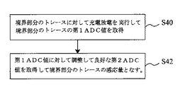
図6は境界問題を解決する第2実施例を示し、タッチコントロールICがトレースTRX1からTRX9を走査する方法は前述したとおりであり、毎回2本のトレースを選択して充電放電を実行して該2本のトレースのADC値を取得して該2本のトレースのうち1本の感応量を判断する。境界部分のトレースTRX10を走査する時、単一トレース走査モードに切り換え、単一のトレースTRX10のみ使用してADC値を判断並びに読み取る。この方法はまず境界部分のトレースTRX10に対して充電放電してトレースTRX10の第1ADC値を取得し、これは図6のステップS40に示されるとおりであり、続いて、ステップS42で第1ADC値に対して調整を行うことで、より良好な第2ADC値を獲得して境界部分のトレースTRX10の感応量となし、例えば第1ADC値に2を乗算して該第2ADC値を得る。 FIG. 6 shows a second embodiment for solving the boundary problem, and the method for the touch control IC to scan the traces TRX1 to TRX9 is the same as described above. The ADC values of the two traces are acquired, and the sensitivity amount of one of the two traces is determined. When scanning the trace TRX10 in the boundary portion, the mode is switched to the single trace scanning mode, and the ADC value is determined and read using only the single trace TRX10. In this method, the trace TRX10 at the boundary portion is first charged and discharged to obtain the first ADC value of the trace TRX10, as shown in step S40 of FIG. 6, and subsequently the first ADC value is set in step S42. By making adjustments to this, a better second ADC value is obtained to obtain the amount of sensitivity of the trace TRX10 in the boundary portion. For example, the first ADC value is multiplied by 2 to obtain the second ADC value.
図7は境界問題を解決する第3実施例を示し、この実施例中、各タッチコントロールIC24及び26は毎回ただ1本のトレースを使用して充電放電を辞意以降してADC値を読み取り、これはステップS50のようであり、続いて、読み取ったADC値を利用して使用するトレースの感応量を判断し、これはステップS52のとおりである。
FIG. 7 shows a third embodiment for solving the boundary problem, in which each
10 小サイズタッチパネル 12 タッチコントロールIC
14 大サイズタッチパネル 20 静電容量式タッチコントロール装置
22 大サイズタッチパネル 24 タッチコントロールIC
26 タッチコントロールIC
10 Small
14 Large
26 Touch control IC
Claims (6)
該第N本のトレースの前のそのうち少なくとも1本のトレースのアナログデジタル変換値及び該第N本のトレースの後のそのうち少なくとも一本のトレースのアナログデジタル変換値を取得するステップ、
取得したアナログデジタル変換値により該第N本のトレースの感応量を決定するステップ、
を有することを特徴とする、静電容量式タッチコントロール装置の検出方法。 In the detection method of the capacitive touch control device, the capacitive touch control device has a touch panel having a plurality of traces, and the Nth of the plurality of traces is connected to the first touch control IC. , The (N + 1) th of the plurality of traces is connected to the second touch control IC, and the detection method includes:
Obtaining an analog-to-digital conversion value of at least one of the traces before the Nth trace and an analog-to-digital conversion value of at least one of the traces after the Nth trace;
Determining a sensitivity amount of the Nth trace from the acquired analog-digital conversion value;
A method for detecting a capacitive touch control device, comprising:
該第N本のトレースを走査して第1アナログデジタル変換値を得るステップ、
第2アナログデジタル変換値を生成して該第N本のトレースの感応量となし、該第2アナログデジタル変換値は該第1アナログデジタル変換値の関数となすステップ、
を有することを特徴とする、静電容量式タッチコントロール装置の検出方法。 In the detection method of the capacitive touch control device, the capacitive touch control device has a touch panel having a plurality of traces, and the Nth of the plurality of traces is connected to the first touch control IC. , The (N + 1) th of the plurality of traces is connected to the second touch control IC, and the detection method includes:
Scanning the N th trace to obtain a first analog to digital conversion value;
Generating a second analog-to-digital conversion value to be a sensitive amount of the Nth trace, wherein the second analog-to-digital conversion value is a function of the first analog-to-digital conversion value;
A method for detecting a capacitive touch control device, comprising:
各一つの該タッチコントロールICが毎回ただ1本のトレースを使用して充電放電を実行してアナログデジタル変換値を取得するステップ、
該アナログデジタル変換値を利用して使用するトレースの感応量を判断するステップ、 を有することを特徴とする、静電容量式タッチコントロール装置の検出方法。 In the detection method of a capacitive touch control device, the capacitive touch control device includes a touch panel having a plurality of traces and a plurality of touch control ICs for scanning the plurality of traces. Is
Each one of the touch control ICs performs charge / discharge using only one trace each time to obtain an analog-digital conversion value;
A method for detecting a capacitive touch control device, comprising: determining a sensitivity amount of a trace to be used using the analog-digital conversion value.
Applications Claiming Priority (1)
| Application Number | Priority Date | Filing Date | Title |
|---|---|---|---|
| TW097112058A TW200943152A (en) | 2008-04-02 | 2008-04-02 | Method of detecting capacitor type touch device |
Publications (1)
| Publication Number | Publication Date |
|---|---|
| JP2009252231A true JP2009252231A (en) | 2009-10-29 |
Family
ID=41132818
Family Applications (1)
| Application Number | Title | Priority Date | Filing Date |
|---|---|---|---|
| JP2008152610A Pending JP2009252231A (en) | 2008-04-02 | 2008-06-11 | Sensing method for capacitive touch control device |
Country Status (3)
| Country | Link |
|---|---|
| US (2) | US8350824B2 (en) |
| JP (1) | JP2009252231A (en) |
| TW (1) | TW200943152A (en) |
Cited By (2)
| Publication number | Priority date | Publication date | Assignee | Title |
|---|---|---|---|---|
| JP2012098782A (en) * | 2010-10-29 | 2012-05-24 | Minebea Co Ltd | Input device and method for electronic device |
| JP2013539581A (en) * | 2010-09-07 | 2013-10-24 | アップル インコーポレイテッド | Touch sensing master / slave control |
Families Citing this family (10)
| Publication number | Priority date | Publication date | Assignee | Title |
|---|---|---|---|---|
| TW200943154A (en) * | 2008-04-02 | 2009-10-16 | Elan Microelectronics Corp | Capacitor-type touch device and method for data transmission applied to the capacitor-type touch device |
| TWI406032B (en) * | 2009-10-22 | 2013-08-21 | Himax Tech Ltd | Readout apparatus and multi-channel readout apparatus for touch panel |
| US20110199328A1 (en) * | 2010-02-18 | 2011-08-18 | Flextronics Ap, Llc | Touch screen system with acoustic and capacitive sensing |
| US8810543B1 (en) | 2010-05-14 | 2014-08-19 | Cypress Semiconductor Corporation | All points addressable touch sensing surface |
| US9772722B2 (en) | 2012-10-22 | 2017-09-26 | Parade Technologies, Ltd. | Position sensing methods and devices with dynamic gain for edge positioning |
| KR102108287B1 (en) * | 2013-08-30 | 2020-05-28 | 주식회사 실리콘웍스 | Touch system and control method thereof |
| US9304680B2 (en) | 2013-11-25 | 2016-04-05 | At&T Mobility Ii Llc | Methods, devices, and computer readable storage device for touchscreen navigation |
| KR102112092B1 (en) | 2013-12-31 | 2020-05-19 | 엘지디스플레이 주식회사 | Touch sensing system |
| KR102207193B1 (en) | 2013-12-31 | 2021-01-26 | 엘지디스플레이 주식회사 | Touch sensing system |
| KR102258597B1 (en) * | 2014-12-10 | 2021-06-01 | 삼성디스플레이 주식회사 | Touch panel and display device including the same |
Citations (3)
| Publication number | Priority date | Publication date | Assignee | Title |
|---|---|---|---|---|
| JPH09269862A (en) * | 1996-03-29 | 1997-10-14 | Pentel Kk | Coordinate input device |
| JP2007172028A (en) * | 2005-12-19 | 2007-07-05 | Alps Electric Co Ltd | Input device |
| JP2008047125A (en) * | 2006-08-18 | 2008-02-28 | Samsung Electronics Co Ltd | Touch screen display apparatus including hybrid touch screen panel controller and method for driving the same |
Family Cites Families (11)
| Publication number | Priority date | Publication date | Assignee | Title |
|---|---|---|---|---|
| US3644935A (en) * | 1970-05-14 | 1972-02-22 | Ibm | Method of identifying connected regions in a large segmented pattern |
| US5534892A (en) * | 1992-05-20 | 1996-07-09 | Sharp Kabushiki Kaisha | Display-integrated type tablet device having and idle time in one display image frame to detect coordinates and having different electrode densities |
| US7663607B2 (en) * | 2004-05-06 | 2010-02-16 | Apple Inc. | Multipoint touchscreen |
| JP4485087B2 (en) * | 2001-03-01 | 2010-06-16 | 株式会社半導体エネルギー研究所 | Operation method of semiconductor device |
| US20070074913A1 (en) * | 2005-10-05 | 2007-04-05 | Geaghan Bernard O | Capacitive touch sensor with independently adjustable sense channels |
| US20080100586A1 (en) * | 2006-10-26 | 2008-05-01 | Deere & Company | Method and system for calibrating a touch screen |
| US8970501B2 (en) * | 2007-01-03 | 2015-03-03 | Apple Inc. | Proximity and multi-touch sensor detection and demodulation |
| US7848825B2 (en) * | 2007-01-03 | 2010-12-07 | Apple Inc. | Master/slave mode for sensor processing devices |
| US8094128B2 (en) * | 2007-01-03 | 2012-01-10 | Apple Inc. | Channel scan logic |
| KR20090014579A (en) * | 2007-08-06 | 2009-02-11 | 삼성전자주식회사 | Liquid crystal display associated with touch panel, method of correcting errors of same, and display system |
| JP4932667B2 (en) * | 2007-10-17 | 2012-05-16 | 株式会社 日立ディスプレイズ | Screen input type image display system |
-
2008
- 2008-04-02 TW TW097112058A patent/TW200943152A/en not_active IP Right Cessation
- 2008-06-11 JP JP2008152610A patent/JP2009252231A/en active Pending
-
2009
- 2009-03-31 US US12/385,095 patent/US8350824B2/en not_active Expired - Fee Related
-
2012
- 2012-08-07 US US13/568,558 patent/US20120299873A1/en not_active Abandoned
Patent Citations (3)
| Publication number | Priority date | Publication date | Assignee | Title |
|---|---|---|---|---|
| JPH09269862A (en) * | 1996-03-29 | 1997-10-14 | Pentel Kk | Coordinate input device |
| JP2007172028A (en) * | 2005-12-19 | 2007-07-05 | Alps Electric Co Ltd | Input device |
| JP2008047125A (en) * | 2006-08-18 | 2008-02-28 | Samsung Electronics Co Ltd | Touch screen display apparatus including hybrid touch screen panel controller and method for driving the same |
Cited By (3)
| Publication number | Priority date | Publication date | Assignee | Title |
|---|---|---|---|---|
| JP2013539581A (en) * | 2010-09-07 | 2013-10-24 | アップル インコーポレイテッド | Touch sensing master / slave control |
| KR101387238B1 (en) | 2010-09-07 | 2014-04-21 | 애플 인크. | Master/slave control of touch sensing |
| JP2012098782A (en) * | 2010-10-29 | 2012-05-24 | Minebea Co Ltd | Input device and method for electronic device |
Also Published As
| Publication number | Publication date |
|---|---|
| TW200943152A (en) | 2009-10-16 |
| US20120299873A1 (en) | 2012-11-29 |
| US20090251429A1 (en) | 2009-10-08 |
| TWI375904B (en) | 2012-11-01 |
| US8350824B2 (en) | 2013-01-08 |
Similar Documents
| Publication | Publication Date | Title |
|---|---|---|
| JP2009252231A (en) | Sensing method for capacitive touch control device | |
| JP4691137B2 (en) | Capacitive touch control device and data transmission method applied to the device | |
| JP4954154B2 (en) | Screen input type image display system | |
| Yang et al. | A touch controller using differential sensing method for on-cell capacitive touch screen panel systems | |
| KR101361341B1 (en) | Integrated touch screen | |
| US7920134B2 (en) | Periodic sensor autocalibration and emulation by varying stimulus level | |
| JP5367175B2 (en) | Touch panel capable of detecting multi-touch and multi-touch detection method of the device | |
| TWI421754B (en) | Capacitive touch device and its control method | |
| CN103902121B (en) | Touch detecting apparatus, the display device with touching detection function and electronic equipment | |
| TWI502463B (en) | Liquid crystal display device | |
| TWI407355B (en) | Detection and Correction of Capacitive Touchpad | |
| JP4733725B2 (en) | Capacitive touch control device and detection method thereof | |
| JP5119054B2 (en) | Capacitive touch control device and data transmission method applied thereto | |
| US9817509B2 (en) | Methods and apparatuses for providing sensing signals for projected capacitive touch sensing using a differential current mode analog circuit | |
| JP2010250522A (en) | Coordinate input device and display device equipped with the same | |
| JP2010061299A5 (en) | ||
| CN101561733A (en) | Method for detecting capacitive type touch-control device | |
| JP2006244446A (en) | Display device | |
| TW200842682A (en) | Digital controller for a true multi-point touch surface useable in a computer system | |
| JP5159450B2 (en) | Capacitive touch control device | |
| JP6082394B2 (en) | High resolution ghost removal gesture | |
| JP2007011228A (en) | Flat display device | |
| JP2006243927A (en) | Display device | |
| TWI453644B (en) | Capacitive touch panel and touch detection method of the same | |
| JP5740888B2 (en) | Image processing apparatus, electronic camera, and program |
Legal Events
| Date | Code | Title | Description |
|---|---|---|---|
| A131 | Notification of reasons for refusal |
Free format text: JAPANESE INTERMEDIATE CODE: A131 Effective date: 20100928 |
|
| A02 | Decision of refusal |
Free format text: JAPANESE INTERMEDIATE CODE: A02 Effective date: 20110301 |