JP2009201945A - Gaming machine - Google Patents
Gaming machine Download PDFInfo
- Publication number
- JP2009201945A JP2009201945A JP2008063199A JP2008063199A JP2009201945A JP 2009201945 A JP2009201945 A JP 2009201945A JP 2008063199 A JP2008063199 A JP 2008063199A JP 2008063199 A JP2008063199 A JP 2008063199A JP 2009201945 A JP2009201945 A JP 2009201945A
- Authority
- JP
- Japan
- Prior art keywords
- symbol display
- symbol
- game
- symbols
- displayed
- Prior art date
- Legal status (The legal status is an assumption and is not a legal conclusion. Google has not performed a legal analysis and makes no representation as to the accuracy of the status listed.)
- Pending
Links
Images


Landscapes
- Slot Machines And Peripheral Devices (AREA)
Abstract
Description
本発明は、所定のシンボル表示領域を固定し、固定されたシンボル表示領域以外のシンボル表示領域上で、シンボルの可変表示が行われるゲーミングマシンに関する。 The present invention relates to a gaming machine in which a predetermined symbol display area is fixed, and symbols are variably displayed on a symbol display area other than the fixed symbol display area.
エンターテインメント性を高めるために、ディスプレイ上に表示された特定シンボルの数に応じた賞を付与するゲーミングマシンが存在する。下記特許文献1においては、フリーゲーム中に、ペイラインに関係なく、「K」シンボルの数に応じて追加的にペイアウトされる点が記載されている。
There is a gaming machine that gives an award according to the number of specific symbols displayed on a display in order to enhance entertainment. In the following
プレイヤを惹きつけるために、新たな特徴を有するゲーミングマシンが望まれている。 In order to attract players, gaming machines having new features are desired.
本発明の一側面である請求項1に係る発明は、ゲーミングマシンであって、複数のシンボル表示領域を表示するディスプレイ、ここで、複数のシンボル表示領域は、それぞれ1つのシンボルを表示する、前記ディスプレイの表示内容、及び、ゲームの進行を制御するプロセッサ、を備え、前記プロセッサは、前記ゲームにおいて、(a)それぞれの前記シンボル表示領域上でシンボルの可変表示を行い、その後、前記複数のシンボル表示領域上に前記複数のシンボルを停止させ、(b)所定のシンボルを、前記シンボル表示領域の最下段から積み上げ、その後、該所定のシンボルが表示されたシンボル表示領域を固定し、(c)次のゲームでは、前記固定されたシンボル表示領域以外のシンボル表示領域上で、シンボルの可変表示を行い、その後、停止させる、ことを特徴とする。
The invention according to
また、本発明の一側面である請求項2に係る発明は、請求項1のゲーミングマシンであって、前記プロセッサは、前記所定のシンボルを積み上げる前に、前記所定のシンボル以外の停止シンボルを消去することを特徴とする。
The invention according to
また、本発明の一側面である請求項3に係る発明は、ゲーミングマシンであって、複数のシンボル表示領域を表示するディスプレイ、ここで、複数のシンボル表示領域は、それぞれ1つのシンボルを表示する、前記ディスプレイの表示内容、及び、ゲームの進行を制御するプロセッサ、ここで、ゲームには第1ゲームと第2ゲームとを含む、を備え、前記プロセッサは、(a)前記第1のゲーム中に、第1シンボルが所定数以上に表示されたときに、ゲームモードを第2ゲームモードに移行させ、(b)前記第2ゲームを所定回数実行し、前記第2ゲームにおいて、(b−1)それぞれの前記シンボル表示領域上でシンボルの可変表示を行い、その後、前記複数のシンボル表示領域上に前記複数のシンボルを停止させ、(b−2)所定のシンボルを、前記シンボル表示領域の最下段から積み上げ、その後、該所定のシンボルが表示されたシンボル表示領域を固定し、(b−3)次のゲームでは、前記固定されたシンボル表示領域以外のシンボル表示領域上で、シンボルの可変表示を行い、その後、停止させることを特徴とする。
The invention according to
また、本発明の一側面である請求項4に係る発明は、請求項3のゲーミングマシンであって、前記プロセッサは、前記所定のシンボルを積み上げる前に、前記所定のシンボル以外の停止シンボルを消去することを特徴とする。
The invention according to
また、本発明の一側面である請求項5に係る発明は、ゲーミングマシンであって、複数のシンボル表示領域を表示するディスプレイ、ここで、複数のシンボル表示領域は、それぞれ1つのシンボルを表示する、前記ディスプレイの表示内容、及び、ゲームの進行を制御するプロセッサ、ここで、ゲームには第1ゲームと第2ゲームとを含む、を備え、前記プロセッサは、(a)前記第1のゲーム中に、第1シンボルが所定数以上に表示されたときに、ゲームモードを第2ゲームモードに移行させ、(b)前記第2ゲームを所定回数実行し、前記第2ゲームにおいて、(b−1)それぞれの前記シンボル表示領域上でシンボルの可変表示を行い、その後、前記複数のシンボル表示領域上に前記複数のシンボルを停止させ、(b−2)前記表示されたシンボルの組合せが、入賞組合せである場合に、当該入賞組合せに対応付けられている賞を付与し、(b−3)所定のシンボルを、前記シンボル表示領域の最下段から積み上げ、その後、該所定のシンボルが表示されたシンボル表示領域を固定し、(b−4)次のゲームでは、前記固定されたシンボル表示領域以外のシンボル表示領域上で、シンボルの可変表示を行い、その後、停止させることを特徴とする。
The invention according to
また、本発明の一側面である請求項6に係る発明は、請求項5のゲーミングマシンであって、前記プロセッサは、前記所定のシンボルを積み上げる前に、前記所定のシンボル以外の停止シンボルを消去することを特徴とする。
The invention according to
本発明によれば、表示される同一シンボルの個数が増加し、払い出し数が増加するので、エンターテインメント性が高まり、プレイヤを惹きつけることができる。 According to the present invention, the number of the same symbols to be displayed is increased and the number of payouts is increased, so that the entertainment property is enhanced and the player can be attracted.
本発明に係るゲーミングマシンについて、スロットマシンに具体化した実施形態に基き図面を参照しつつ詳細に説明する。
本実施形態のスロットマシン1は、例えば、液晶ディスプレイ等の画像表示装置を有し、画像表示装置に対して各種シンボルの画像を表示させることにより遊技を行う。すなわち、本実施形態のスロットマシン1は、ビデオスロットマシンとして実現できる。
また、本実施形態のスロットマシン1は、メカニカルリールと、メカニカルリールの前面に配置された透明液晶表示装置とからなるハイブリッド型のスロットマシンとしても実現できる。
また、本実施形態のスロットマシン1は、メカニカルリールを有するメカニカルスロットマシンとしても実現できる。
A gaming machine according to the present invention will be described in detail with reference to the drawings based on an embodiment embodied in a slot machine.
The
The
Further, the
なお、以下の説明においては、主に、ビデオリールを用いたスロットマシンについて説明を行うが、本発明が、適用可能な限度においてメカニカルリールを用いたスロットマシンにも適用可能である。 In the following description, a slot machine using a video reel will be mainly described. However, the present invention can be applied to a slot machine using a mechanical reel as far as applicable.
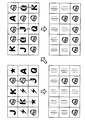
本実施形態のスロットマシン1では、特定シンボルが停止されると、特定シンボルが、シンボル表示部の最下段から積み上げられる(図1の左上段参照)。その後、特定シンボルが表示されたシンボル表示部が固定された状態で、その他のシンボル表示部上で、リール(シンボル)の可変表示が行われる(図1の左下段参照)。特定シンボルが新たに停止されると、該特定シンボルが、シンボル表示部の最下段から積み上げられる(図1の右上段参照)。その後、特定シンボルが表示されたシンボル表示部が固定された状態で、その他のシンボル表示部上で、リール(シンボル)の可変表示が行われる(図1の右下段参照)。
In the
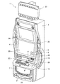
本実施形態のスロットマシン1の概略構成について、図面を参照しつつ説明する。図2は本実施形態に係るスロットマシン1の外観を示している。
本実施形態のスロットマシン1は、カジノなどの遊技場に設置されるアップライト型のスロットマシンである。なお、図2に示すスロットマシン1の外観は、本発明における単なる一例であり、本発明は当該外観に限定されるものではない。
A schematic configuration of the
The
スロットマシン1は、キャビネット2を有している。キャビネット2は、所定の遊技態様を実行するための電気的又は機械的部品を収容する収納部である。
The
スロットマシン1は、種々の遊技情報を表示するために、アッパー表示部3A、メイン表示部3B、及び、アンダー表示部3Cをキャビネット2の前面に備えている。アッパー表示部3Aは、キャビネット2の上段にあり、メイン表示部3Bは、キャビネット2の中段にあり、アンダー表示部3Cは、キャビネットの下段にある。
The
アッパー表示部3Aは、液晶パネルで構成されている。演出画像、ゲーム時のペイアウトテーブル、ゲームルール等がアッパー表示部3Aに表示される。
The
メイン表示部3Bは、液晶パネルで構成されている。メイン表示部3Bは、例えば、図3に示すように、3×5のマトリクス状に、15個のシンボル表示部111A〜115A、111B〜115B、111C〜115Cが表示される。
The
また、それぞれのシンボル表示部において、リールの可変表示が行われる。また、複数のシンボルがリールに描かれている。リールが停止すると、1つのシンボルがシンボル表示部に表示される。本実施形態においては、それぞれのシンボル表示部に1つのリールが対応付けられている。すなわち、本実施形態においては、15個のリールが用いられる。なお、シンボル表示部の数は適宜設定可能である。 Further, reels are variably displayed on each symbol display section. A plurality of symbols are drawn on the reel. When the reel stops, one symbol is displayed on the symbol display section. In the present embodiment, one reel is associated with each symbol display section. That is, in this embodiment, 15 reels are used. The number of symbol display portions can be set as appropriate.
メイン表示部3Bの液晶パネルの前面には、タッチパネル4が設けられている。プレイヤは、タッチパネル4を操作して各種の指示を入力することができる。また、ペイアウト数表示部5及びクレジット数表示部6がメイン表示部3Bに設けられている。ペイアウト数表示部5及びクレジット数表示部6の表示位置は任意であり、例えば、メイン表示部3Bの右下部分に設けられる。また、ベット数を表示するためのベット数表示部を設けてもよい。ペイアウト数表示部5には、プレイヤに付与される配当額(すなわち、通常ゲーム及びフリーゲームで所定のシンボルが所定数表示された場合に付与される配当額)が表示される。クレジット数表示部6には、現在プレイヤが所有しているクレジット数が表示される。
A
アンダー表示部3Cは、液晶パネルで構成されている。アンダー表示部3Cには、カードに記録されているポイント数、及び/又は、ゲームのポイント数が表示される。また、カードが挿入されていないとき、及び/又は、カードの読取が失敗したときは、その旨が表示される。
また、アンダー表示部3Cの周辺には、カード読取部19が配置されている。カード読取部19は、プレイヤが所有するカードに記憶された情報を読み取ることができる。
The under
A
アッパー表示部3A、メイン表示部3B、及び、アンダー表示部3Cは、例えば、上述したとおり液晶パネルで構成されるが、本発明はこれに限定されない。すなわち、各表示部は、CRTディスプレイ、プラズマディスプレイ、LEDディスプレイ、その他公知の表示装置であってもよい。
Although the
腰パネル7は、アンダー表示部3Cの下側に位置し、プラスチックパネルで構成される。遊技機に関連するキャラクタの絵、及び、遊技機の名称等が描かれ、バックライトによって照らされる。腰パネル7は、液晶ディスプレイ、CRTディスプレイ、プラズマディスプレイ、LEDディスプレイ、その他公知の表示装置であってもよい。
The
また、メイン表示部3Bは、メカニカルリールと、メカニカルリールの前面に配置された透明液晶表示装置とからなるハイブリッド型として構成してもよい。これにより、メカニカルリールに描かれた図柄は、透明液晶表示装置を介して視認される。また、透明液晶表示装置には、メカニカルリールの数と等しい表示窓を設け、当該表示窓を通じてメカニカルリールに描かれた図柄を視認できるよう構成することが望ましい。なお、以下の説明においては、主に、ビデオリールを用いたスロットマシンについて説明を行うが、本発明が適用可能な限度においてメカニカルリールを用いたスロットマシンにも適用可能であることはいうまでもない。また、メカニカルリールを用いる場合は、メカニカルリールは、図示しないモータによって回転・停止が制御される。
The
メイン表示部3Bの下側には、操作テーブル8が手前側に突出されて設けられている。操作テーブル8には、両替ボタン、払い戻しボタン、ヘルプボタン、BETボタン、及び、スタートボタンなどの各種操作ボタン26が配置されている。これらのボタンの配置位置は任意である。また、必要に応じて、前記ボタンの一部を削除してもよいし、新たなボタンを追加、置換してもよい。また、操作テーブル8には、コイン投入部17、紙幣投入部18が配置されている。
An operation table 8 is provided on the lower side of the
また、キャビネット2の下部には、コイン払出口と、コイン受け部21が形成されている。コイン払出口は、両替ボタンや払い戻しボタンの入力により、コインが払い出される部分である。そして、コイン受け部21は、コイン払出口から払い出されたコインを受ける部分である。コイン払出口の内部には、センサ等より構成されるコイン検出部が配置されている。コイン検出部は、コイン払出口から払い出されるコインの枚数を検出する。
Further, a coin payout opening and a
さらに、スロットマシン1のキャビネット2の周囲には、入賞の際やフリーゲーム中に所定の点灯態様で点灯する発光部25が配置されている。更に、キャビネット2の側面には、音声の出力を行うスピーカ34が設けられている。なお、発光部25及びスピーカ34の配置位置は、任意である。
Further, around the
スロットマシン1は、キャビネット2の上部にトッパー演出装置27を備える。このトッパー演出装置27は、矩形ボード形状を有しており、アッパー表示部3Aと略平行になるように配置されている。なお、トッパー演出装置27の形状は任意である。トッパー演出装置27には、種々の情報が表示される。
The
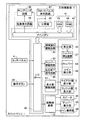
次に、上述したスロットマシン1の内部構成について、図4及び図5を参照しつつ説明する。図4は、スロットマシン1全体の内部構成を示したブロック図である。図4に示すように、スロットマシン1は、後述する制御プログラムを実行するコントローラ41を含む主制御基板71を中心に複数の構成要素を有している。その主制御基板71は、コントローラ41、乱数発生回路45、サンプリング回路46、クロックパルス発生回路47、分周器48、照明演出駆動回路61、ホッパー駆動回路63、払出完了信号回路65、及び、表示部駆動回路67を有している。
Next, the internal configuration of the above-described
コントローラ41は、メインCPU42と、RAM43と、ROM44とを有している。メインCPU42は、ROM44に記憶されているプログラムに従って作動し、I/Oポート49を介して他の構成要素との信号の入出力を行って、スロットマシン1全体の動作制御を行う。RAM43はメインCPU42が作動する際に用いるデータやプログラムが記憶される。例えば、サンプリング回路46によりサンプリングされる乱数値がゲーム開始後、一時的に保持される。また、後述するコードナンバが記憶されている。
The
ROM44には、メインCPU42が実行するプログラムと、恒久的なデータが記憶されている。
ROM44に記憶されているプログラムには、ゲームプログラム及びゲームシステムプログラム(以下、ゲームプログラム等という)が含まれている。さらに、そのゲームプログラムには、抽選プログラムが含まれている。
また、実施形態のスロットマシンをビデオスロットマシンとして実現する場合は、ビデオリールを構成するシンボルの画像が、ROM44に記憶される。
The
The programs stored in the
Further, when the slot machine of the embodiment is realized as a video slot machine, an image of a symbol constituting a video reel is stored in the
抽選プログラムは、メイン表示部3Bの各シンボル表示部に停止されるシンボルに対応するコードナンバを決定するためのプログラムである。コードナンバとシンボルとの対応関係については後述する。
The lottery program is a program for determining a code number corresponding to a symbol stopped in each symbol display section of the
乱数発生回路45は、メインCPU42の指示に従って作動し、一定範囲の乱数を発生させる。サンプリング回路46は、メインCPU42の指示に従い、乱数発生回路45が発生させた乱数の中から任意の乱数を抽出すると共に、その抽出した乱数をメインCPU42に入力する。クロックパルス発生回路47は、メインCPU42を作動させるための基準クロックを発生させ、分周器48はその基準クロックを一定周期で分周した信号をメインCPU42に入力する。
The random
さらに、主制御基板71には、タッチパネル4が接続されている。このタッチパネル4は、メイン表示部3Bの前面に配置され、プレイヤにより接触された部分の座標位置を特定し、特定した座標位置情報に基づいてプレイヤがどこに触れたか、及び/又は、触れた箇所がどの方向に移動したのかを判別することができる。そして、判別に応じた信号が、I/Oポート49を介してメインCPU42に入力されるように構成されている。
Further, the
さらに、主制御基板71には、遊技の実行を指示するための操作ボタン26(上述したスタートボタン等)が操作スイッチを介して接続されており、それらのボタン押下に応じた信号が、I/Oポート49を介してメインCPU42に入力されるようになっている。
Further, the
照明演出駆動回路61は、上述した発光部25及びトッパー演出装置27に照明演出を行わせるための演出信号を出力する。トッパー演出装置27は、発光部25を介して、照明演出駆動回路61に接続されている。
The illumination
ホッパー駆動回路63はメインCPU42の制御に従ってホッパー64を駆動させる。それによって、ホッパー64はコインの払出を行うための動作を行い、コイン払出口へとコインを払出する。払出完了信号回路65は、接続されているコイン検出部66からコインの枚数値データを受信し、受信した枚数値が設定された枚数の値に達したときにコインの払出完了を通知する信号をメインCPU42に入力する。コイン検出部24は、ホッパー64により払出されたコインの枚数を計測し、その計測した枚数値のデータを払出完了信号回路65に入力する。表示部駆動回路67は、ペイアウト数表示部5、クレジット数表示部6等の各種表示部の表示動作を制御する。
The
さらに、主制御基板71には副制御基板72が接続されている。副制御基板72は、図5に示すように、主制御基板71からコマンドを入力して、各表示部の表示制御、スピーカ34による音声の出力制御を行う。この副制御基板72は、主制御基板71を構成する回路基板とは別の回路基板上に構成される。また、副制御基板72は、マイクロコンピュータ(以下、「サブマイクロコンピュータ」という。)73を主たる構成要素とし、スピーカ34から出力される音声を制御する音源IC78、増幅器としてのパワーアンプ79、及びアッパー表示部3A及びメイン表示部3Bを表示制御手段として作動させる画像制御回路81を有している。
Further, a
サブマイクロコンピュータ73は、サブCPU74と、プログラムROM75と、ワークRAM76と、I/Oポート77、80を有している。サブCPU74は、主制御基板71から送信された制御命令に従って制御動作を行う。副制御基板72はクロックパルス発生回路、分周器、乱数発生器及びサンプリング回路を備えていないが、サブCPU74の動作プログラム上で乱数サンプリングを実行するように構成されている。プログラムROM75は、サブCPU74で実行する制御プログラムを記憶している。ワークRAM76は、上記制御プログラムをサブCPU74で実行するときの一時メモリとして構成されている。
The sub microcomputer 73 has a
画像制御回路81は、画像制御CPU82、画像制御ワークRAM83、画像制御プログラムROM84、INポート85、画像ROM86、ビデオRAM87及び画像制御IC88を有している。画像制御CPU82は、サブマイクロコンピュータ73で設定されたパラメータに基づき、画像制御プログラムROM84に記憶されている画像制御プログラムに従い、アッパー表示部3A及びメイン表示部3Bで表示される画像を決定する。例えば、アッパー表示部3Aにはペイアウトテーブルやヘルプ画面を表示する。また、メイン表示部3Bにはシンボル表示部111A〜111C、112A〜112C、113A〜113C、114A〜114C、及び115A〜115Cのそれぞれにおいて、リール(シンボル)を可変表示させ、また、シンボルを停止させる。
The image control circuit 81 includes an
画像制御プログラムROM84は、アッパー表示部3A及びメイン表示部3Bにおける表示に関する画像制御プログラムや各種選択テーブルが記憶されている。画像制御ワークRAM83は、画像制御プログラムを画像制御CPU82で実行するときの一時メモリとして構成されている。画像制御IC88は、画像制御CPU82で決定された内容に応じた画像を形成し、アッパー表示部3A及びメイン表示部3Bに出力する。
The image
画像ROM86は、画像を形成するためのドットデータを格納している。ビデオRAM87は、画像制御IC88で画像を形成するときの一時記憶手段として作動する。
The
なお、上述したスロットマシン1の内部構成は、単なる一例であり、本実施形態は、上記内部構成に限定されるものではない。例えば、着脱可能なメモリカード及び/又はPLD(Programmable Logic Device)を装着可能に構成し、必要な情報をメモリカード及び/又はPLDから読み出すようにしてもよい。
Note that the internal configuration of the
本実施形態のスロットマシン1では、遊技価値として、コイン、紙幣又はこれらに相当する電子的な有価情報(クレジット)が用いられる。但し、本発明に適用可能な遊技価値は、これに限定されるものではなく、例えば、メダル、トークン、電子マネー、チケットを挙げることができる。本実施形態においては、主に、クレジットが付与されるものとして説明するが、本発明はこの実施形態に限定されるものではない。
In the
次に、シンボル表示部上で可変表示されるリールに描かれているシンボルについて図6を参照しつつ説明する。図6は、シンボル表示部上で可変表示されるリールに描かれるシンボルの種類の一例を示している。 Next, the symbols drawn on the reel variably displayed on the symbol display section will be described with reference to FIG. FIG. 6 shows an example of the types of symbols drawn on the reel variably displayed on the symbol display section.
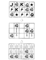
本実施形態で用いられるシンボルには、KINGシンボル51A、QUEENシンボル51B、JACKシンボル51C、ACEシンボル51D、TENシンボル51E、BELLシンボル51F、THUNDERシンボル51G、STARシンボル51Hが含まれる。
The symbols used in the present embodiment include a
なお、1つのリールに描かれるシンボルの数は任意であり、また、描かれるシンボルの種類も任意である。 Note that the number of symbols drawn on one reel is arbitrary, and the type of symbols drawn is also arbitrary.
図7は、各シンボル表示部において可変表示されるリールの一例を示した図である。図7に示されるように、図6で示したシンボルが、リール上に所定の順番で描かれている。
なお、図7に示したシンボルの順序は単なる一例であり、シンボルの順序は適宜設定可能である。
また、シンボル表示部ごとに、用いるリールが異なってもよい。また、シンボル表示部ごとに複数のリールを有しておき、設定されたペイアウト率によって選択できるようにしてもよい。
FIG. 7 is a diagram showing an example of a reel variably displayed on each symbol display section. As shown in FIG. 7, the symbols shown in FIG. 6 are drawn on the reel in a predetermined order.
Note that the order of symbols shown in FIG. 7 is merely an example, and the order of symbols can be set as appropriate.
Moreover, the reel to be used may be different for each symbol display unit. Further, a plurality of reels may be provided for each symbol display section so that selection can be made according to a set payout rate.
次に、本実施形態のスロットマシン1において行われるゲームについて説明する。本実施形態で行われるゲームは、2つのゲームから構成される。2つのゲームは、通常ゲーム、フリーゲームである。フリーゲームについては、後述する。
Next, the game performed in the
通常ゲームについて説明する。通常ゲームでは、メイン表示部3B上のシンボル表示部111A〜115A、111B〜115C、111C〜115Cに表示された同一シンボルの個数に基いて、入賞組合せが決定され、その入賞組合せに対応した賞が付与される。
A normal game will be described. In the base game, a winning combination is determined based on the number of the same symbols displayed on the
プレイヤがBETボタンを操作してベット数を設定し、スタートボタンを押下することにより、各シンボル表示部において、リールが回転を開始する。これにより、図8に示すように各シンボル表示部上において、リールに描かれたシンボル列が、可変表示される。そして、所定時間が経過すると、各シンボル表示部において、リールの回転が停止する。それに伴って、各リール上の1つのシンボルが、図9に示すようにメイン表示部3B上のシンボル表示部にそれぞれ表示される。なお、スクロールの方向は、上方向から下方向のみに限らず、下方向から上方向でもよい。また、リール表示部ごとに、スクロールする方向が異なってもよい。また、ゲームごとに、スクロールの方向が異なってもよい。
When the player operates the BET button to set the number of bets and presses the start button, the reel starts rotating in each symbol display section. Thereby, as shown in FIG. 8, the symbol row drawn on the reel is variably displayed on each symbol display section. Then, when the predetermined time has elapsed, the rotation of the reels is stopped in each symbol display section. Accordingly, one symbol on each reel is displayed on the symbol display section on the
本実施形態においては、シンボル表示部上の停止順序は適宜設定可能である。すなわち、すべてのシンボル表示部(シンボル表示部111A〜115A、111B〜115C、111C〜115C)上で、同時にリールが停止することができる。
リールの停止後、表示された同一シンボルの個数に基いて、入賞組合せが決定され、当該入賞組合せに対応した賞が付与される。入賞組合せに入賞した場合には、当該入賞組合せに応じた配当額をベット数で乗算した額がプレイヤに付与される。
In the present embodiment, the stop order on the symbol display unit can be set as appropriate. That is, the reels can be stopped simultaneously on all the symbol display portions (
After the reels are stopped, a winning combination is determined based on the number of the same symbols displayed, and a prize corresponding to the winning combination is awarded. When winning a winning combination, the player is awarded an amount obtained by multiplying the payout amount corresponding to the winning combination by the number of bets.
次に、本実施形態のスロットマシン1における通常ゲーム及びフリーゲームに対する入賞組合せ及び付与される賞について図10に基づき説明する。図10は、本実施形態において利用されるペイアウトテーブルの内容を示している。ペイアウトテーブルには、入賞組合せと付与される賞とが対応づけられている。
Next, winning combinations for the base game and the free game in the
ここで、図10に示す配当額は、ベット数が「1」である場合の配当額を示している。すなわち、ベット数が「1」である場合には、図10に示す配当額が払い出されるが、ベット数が「2」以上である場合には、図10に示す配当額に当該ベット数を乗じた額が払い出される。 Here, the payout amount shown in FIG. 10 indicates the payout amount when the bet number is “1”. That is, when the bet number is “1”, the payout amount shown in FIG. 10 is paid out. When the bet number is “2” or more, the payout amount shown in FIG. 10 is multiplied by the bet number. The amount will be paid out.
例えば、シンボル表示部111A〜115A、111B〜115C、111C〜115Cに、5個のKINGシンボル51Aが表示されている場合は、50クレジットにベット数を乗じた額が払い出される。
For example, when five
また、シンボル表示部111A〜115A、111B〜115C、111C〜115Cに、4個のACEシンボル51Dが表示されている場合は、80クレジットにベット数を乗じた額が払い出される。
Further, when four
同様に、図10に示す入賞組合せ毎に配当額が設定されている。但し、シンボル表示部111A〜115A、111B〜115C、111C〜115Cに表示されたシンボルが、図10に示した入賞組合せのいずれでもない場合は、ハズレであり、ハズレに対する払い出しは行われない。
Similarly, a payout amount is set for each winning combination shown in FIG. However, if the symbols displayed on the
なお、図10に示されるペイアウトテーブルは一例であり、入賞組合せの種類及び配当額については、適宜設定可能である。また、複数のペイアウトテーブルを備えておき、設定されるペイアウト率に応じて選択可能となるよう構成してもよい。また、フリーゲームで用いられるペイアウトテーブルを、通常ゲームで用いられるペイアウトテーブルと異ならせてもよい。 Note that the payout table shown in FIG. 10 is an example, and the types of winning combinations and the payout amount can be set as appropriate. Further, a plurality of payout tables may be provided so that selection can be made according to a set payout rate. Further, the payout table used in the free game may be different from the payout table used in the normal game.
続いて、本実施形態のスロットマシン1において実行されるメイン制御プログラムについて、図面を参照しつつ詳細に説明する。図11は、メイン制御プログラムのフローチャートである。
Subsequently, a main control program executed in the
まず、電源スイッチの投入(電源の投入)が行われると、主制御基板71、副制御基板72を夫々起動し、コントローラ41はS1の初期設定処理を実行する。初期設定処理において、メインCPU42は、ROM44に記憶されているBIOSを実行して、BIOSに組み込まれている圧縮データをRAM43に展開する。そして、RAM43に展開されたBIOSの実行と、各種周辺装置の診断と初期化を行う。さらに、メインCPU42は、ゲームプログラム等をROM44からRAM43に書き込み、ペイアウト率設定用データ及び国識別情報を取得する。メインCPU42は、初期設定処理の実行中において、各プログラムに対する認証処理も行う。
First, when the power switch is turned on (power is turned on), the
S2において、メインCPU42は、ゲームプログラム等をRAM43より順次読み出して実行し、メイン遊技処理を行う。メイン遊技処理を実行することにより、本実施形態のスロットマシン1でのゲームが行われる。そして、メイン遊技処理は、スロットマシン1に電源が供給されている間、繰り返し実行される。
In S2, the
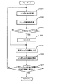
次に、上記S2のメイン遊技処理のサブ処理について図12に基づき説明する。図12は本実施形態のスロットマシン1におけるメイン遊技処理プログラムのフローチャートである。なお、以下のフローチャートに示す処理を実行するためのプログラムはスロットマシン1が備えているROM44やRAM43に記憶されており、メインCPU42により実行される。
Next, the sub-process of the main game process in S2 will be described with reference to FIG. FIG. 12 is a flowchart of the main game processing program in the
S11において、スタート受付処理が実行される。スタート受付処理では、プレイヤにより、コインの投入や操作ボタン26内のBETボタンを用いたベット操作が行われる。
In S11, a start acceptance process is executed. In the start acceptance process, the player performs coin insertion and a bet operation using the BET button in the
そして、S12において、操作ボタン26内のスタートボタンが押下されたか否か判断する。この判断は、スタートボタンの押下に応じてメインCPU42に入力される信号に基づいて行われる。ここで、スタートボタンが押下されていないと判断した場合(S12:NO)には、再びスタート受付処理(S11)に戻る。S11では、ベット数の修正等の操作が可能となる。一方、スタートボタンが押下されたと判断した場合(S12:YES)には、上記ベット操作に基づき設定されたベット数を、プレイヤが現在所有するクレジット数から減算すると共に、ベット情報としてRAM43に格納する。その後、S13に進む。
In S12, it is determined whether or not the start button in the
S13において、シンボル抽選処理が実行される。具体的には、まず、RAM43に記憶された抽選プログラムを実行することにより、所定の乱数値範囲から乱数値をサンプリングする。その後、サンプリングされた乱数値とテーブルに基づいて、それぞれのシンボル表示部に停止されるシンボルを決定する。
In S13, a symbol lottery process is executed. Specifically, first, a random number value is sampled from a predetermined random value range by executing a lottery program stored in the
S13における処理について詳細に説明する。図13は、図7で示したリールに描かれているシンボルとコードナンバとを対応付けたテーブルの一例である。図14は、乱数値とコードナンバとを対応付けたテーブルの一例である。所定の乱数値範囲(例えば、0〜65535)からサンプルされた乱数値に基き、図14に示されるテーブルを利用してコードナンバを決定する。決定されたコードナンバと図13に示されるテーブルとを利用することにより、停止すべきシンボルが決定される。 The process in S13 will be described in detail. FIG. 13 is an example of a table in which symbols drawn on the reels shown in FIG. 7 are associated with code numbers. FIG. 14 is an example of a table in which random numbers and code numbers are associated with each other. Based on the random number values sampled from a predetermined random value range (for example, 0 to 65535), the code number is determined using the table shown in FIG. The symbol to be stopped is determined by using the determined code number and the table shown in FIG.
ここで、図14に示すように、コードナンバごとに対応付けられている乱数値の数が異なるので、図13に示されるそれぞれのシンボルにおける出現確率を制御することができる。例えば、図14においては、コードナンバ“4”には、乱数値“512”〜“760”が対応付けられ、コードナンバ“5”には、乱数値“761”〜“767”が対応付けられている。これにより、コードナンバ“4”の方がコードナンバ“5”よりも出現しやすいので、図7に示すリールにおいては、コードナンバ“4”に対応付けられているJACKシンボル51Cの方が、コードナンバ“5”に対応付けられているTHUNDERシンボル51Gよりも表示される確率が高いことになる。
Here, as shown in FIG. 14, since the number of random numbers associated with each code number is different, the appearance probability in each symbol shown in FIG. 13 can be controlled. For example, in FIG. 14, the code number “4” is associated with random values “512” to “760”, and the code number “5” is associated with random values “761” to “767”. ing. As a result, the code number “4” is more likely to appear than the code number “5”. Therefore, in the reel shown in FIG. 7, the
例えば、シンボル表示部113Aに対し、図7に示されるリールを利用した場合において、“1136”がサンプリングされた場合、図14のテーブルに基づいて、コードナンバとして“08”が決定される。そして、図13に示すテーブルを利用することにより、コードナンバ“08”に対応するTENシンボル51Eがシンボル表示部113Aに停止すべきシンボルとして決定される。
For example, when “1136” is sampled when the reel shown in FIG. 7 is used for the
また、図15に示すように、サンプリングされる乱数値とシンボルとを直接対応づけてもよい。 Further, as shown in FIG. 15, the random number value to be sampled may be directly associated with the symbol.
図12に説明を戻す。S14において、リール回転処理が実行される。具体的には、まず、シンボル表示部111A〜115A、111B〜115C、111C〜115C上で、それぞれリールが可変表示される。その後、単位ゲームに対する演出パターン(メイン表示部3Bへの画像の表示やスピーカ34からの音の出力等のパターン)が開始される。ここで、単位ゲームとは、それぞれのリールの可変表示が開始し、その後、すべてのリールが停止表示される一連の処理のことをいう。
Returning to FIG. In S14, a reel rotation process is executed. Specifically, first, the reels are variably displayed on the
そして、所定時間が経過すると所定の順序で、シンボル表示部111A〜115A、111B〜115C、111C〜115C上のリールの回転が停止する。これにより、シンボル表示部111A〜111C、112A〜112C、113A〜113C、114A〜114C、及び、115A〜115Cのそれぞれにおいて、シンボルが停止される。
Then, when a predetermined time elapses, the reels on the
その後、S15において、メイン表示部3Bに表示されたシンボルの組合せが入賞組合せであるか否かについて判断する。この判断は、RAM43に記憶された各シンボル表示部111A〜115A、111B〜115C、111C〜115Cのコードナンバに基く。
Thereafter, in S15, it is determined whether or not the symbol combination displayed on the
入賞組合せが成立していると判断した場合(S15:YES)には、S16に移行する。一方、いずれの入賞組合せも成立していないと判断した場合(S15:NO)には、S17に移行する。 If it is determined that a winning combination is established (S15: YES), the process proceeds to S16. On the other hand, if it is determined that no winning combination has been established (S15: NO), the process proceeds to S17.
S16において、S15で決定された入賞組合せに応じた配当額を払い出す。その後、S17に移行する。 In S16, a payout amount corresponding to the winning combination determined in S15 is paid out. Thereafter, the process proceeds to S17.
S17において、フリーゲームトリガーが成立しているか否かが判断される。本実施形態においては、STARシンボル51Hが所定個数以上表示された場合に、S17において「YES」と判断される。
フリーゲームトリガーが成立していると判断した場合は(S17:YES)、S18に進む。S18において、フリーゲームが実行される。フリーゲームの詳細については後述する。
In S17, it is determined whether or not a free game trigger is established. In the present embodiment, when a predetermined number or more of the
When it is determined that the free game trigger is established (S17: YES), the process proceeds to S18. In S18, a free game is executed. Details of the free game will be described later.
一方、フリーゲームトリガーが成立していないと判断した場合は(S17:NO)、メイン遊技処理を終了する。 On the other hand, when it is determined that the free game trigger is not established (S17: NO), the main game process is terminated.
次に、フリーゲームについて説明する。図16は、フリーゲーム処理のフローチャートである。フリーゲームでは、遊技価値を消費しない。また、プレイヤの操作ボタンの操作を必要とせずにゲームが自動的に連続して行われる。 Next, the free game will be described. FIG. 16 is a flowchart of the free game process. Free games do not consume game value. Further, the game is automatically and continuously performed without requiring the player to operate the operation buttons.
S21において、抽選の対象となるシンボル表示部に対して、シンボル抽選処理が実行される。S21のシンボル抽選処理は、S13のシンボル抽選処理と同じであるので、説明を省略する。
S22において、可変表示の対象となるシンボル表示部に対して、リール回転制御処理が実行される。S22のリール回転制御処理は、S14のリール回転制御処理と同じであるので、説明を省略する。
In S21, a symbol lottery process is executed for the symbol display unit to be a lottery target. Since the symbol lottery process in S21 is the same as the symbol lottery process in S13, the description thereof is omitted.
In S22, a reel rotation control process is executed for the symbol display unit that is the target of variable display. Since the reel rotation control process of S22 is the same as the reel rotation control process of S14, the description is omitted.
S23において、メイン表示部3Bに表示されたシンボルの組合せが、入賞組合せであるか否かについて判断する。この判断は、RAM43に記憶された各シンボル表示部111A〜115A、111B〜115C、111C〜115Cのコードナンバに基く。
In S23, it is determined whether or not the combination of symbols displayed on the
入賞組合せが成立していると判断した場合(S23:YES)には、S24に移行する。一方、いずれの入賞組合せも成立していないと判断した場合(S23:NO)には、S25に移行する。
S24において、S23で決定された入賞組合せに応じた配当額を払い出す。その後、S25に移行する。
If it is determined that a winning combination has been established (S23: YES), the process proceeds to S24. On the other hand, if it is determined that no winning combination has been established (S23: NO), the process proceeds to S25.
In S24, the payout amount corresponding to the winning combination determined in S23 is paid out. Thereafter, the process proceeds to S25.
S25において、特定シンボル(本実施形態では、BELLシンボル51F)を、シンボル表示部の最下段(本実施形態では、シンボル表示部111C〜115C)から積み上げる。
In S25, the specific symbol (
S26において、BELLシンボル51Fが表示されているシンボル表示部を固定する。すなわち、BELLシンボル51Fが表示されているシンボル表示部においては、以後のフリーゲームでは可変表示が行われないように設定する。このとき、シンボル表示部ごとにフラグを用意し、フラグを用いて設定することができる。
In S26, the symbol display part on which the
S27において、フリーゲームの実行回数が所定回数に達したか否かを判断する。ここで、所定回数は、固定値でもよく、また、フリーゲーム移行時の条件に応じて決定してもよい。
所定回数に達していないと判断した場合は(S27:NO)、S21に戻る。一方、所定回数に達したと判断した場合は(S27:YES)、フリーゲームを終了する。
In S27, it is determined whether or not the number of executions of the free game has reached a predetermined number. Here, the predetermined number of times may be a fixed value, or may be determined according to conditions at the time of transition to the free game.
If it is determined that the predetermined number has not been reached (S27: NO), the process returns to S21. On the other hand, if it is determined that the predetermined number of times has been reached (S27: YES), the free game is terminated.
図17は、シンボル表示部の表示内容の一例を示している。
図17の上段は、S22(図16)のリール回転制御処理によって各シンボル表示部に停止したシンボルを示している。図17の上段に示すように、シンボル表示部112A、114A、114B、115B、111C上に、BELLシンボル51Fが停止している。
FIG. 17 shows an example of the display contents of the symbol display unit.
The upper part of FIG. 17 shows symbols stopped on each symbol display portion by the reel rotation control process of S22 (FIG. 16). As shown in the upper part of FIG. 17, the
S25の処理において、シンボル表示部111Cに停止しているBELLシンボル51Fは、すでにシンボル表示部の最下段に位置しているので、移動しない(図17の中段参照)。
In the process of S25, the
S25の処理において、シンボル表示部112Aに停止しているBELLシンボル51Fは、シンボル表示部112C(シンボル表示部の最下段)に移動する(図17の中段参照)。
In the process of S25, the
S25の処理において、シンボル表示部114Bに停止しているBELLシンボル51Fは、シンボル表示部114C(シンボル表示部の最下段)に移動する(図17の中段参照)。
In the process of S25, the
S25の処理において、シンボル表示部114Aに停止しているBELLシンボル51Fは、シンボル表示部114Bに移動する(図17の中段参照)。すなわち、シンボル表示部114Aに停止しているBELLシンボル51Fは、シンボル表示部114Cに移動したBELLシンボル51Fに積まれることになる。
In the process of S25, the
S25の処理において、シンボル表示部115に停止しているBELLシンボル51Fは、シンボル表示部115C(シンボル表示部の最下段)に移動する(図17の中段参照)。
In the processing of S25, the
そして、シンボル表示部114B、111C、112C、114C、115Cを固定した状態で、すなわち、BELLシンボル51Fが固定された状態で、次のフリーゲームにおけるリールの可変表示(S22のリール回転制御処理)が行われる(図17の下段参照)。
Then, with the
図18は、シンボル表示部の表示内容の一例を示している。
図18の上段は、図17の下段において実行されたリール回転制御処理(S22)によって各シンボル表示部に停止したシンボルを示している。
図18の上段に示すように、さらに、シンボル表示部112A、113A、114Aに、BELLシンボル51Fが停止している。
FIG. 18 shows an example of the display contents of the symbol display unit.
The upper part of FIG. 18 shows symbols stopped on each symbol display unit by the reel rotation control process (S22) executed in the lower part of FIG.
As shown in the upper part of FIG. 18, the
S25の処理において、シンボル表示部112Aに停止しているBELLシンボル51Fは、シンボル表示部112Bに移動する(図18の中段参照)。すなわち、シンボル表示部112Aに停止しているBELLシンボル51Fは、シンボル表示部112Cで固定されたBELLシンボル51Fに積まれることになる。
In the process of S25, the
S25の処理において、シンボル表示部113Aに停止しているBELLシンボル51Fは、シンボル表示部113C(シンボル表示部の最下段)に移動する(図18の中段参照)。
In the process of S25, the
S25の処理において、シンボル表示部114Aに停止しているBELLシンボル51Fは、すでにシンボル表示部114B及び114C上において、BELLシンボル51Fが固定されているので、移動しない(図18の中段参照)。
In the processing of S25, the
そして、シンボル表示部114A、112B、114B、111C〜115Cが固定した状態で、すなわち、BELLシンボル51Fが固定した状態で、次のフリーゲームにおけるリールの可変表示(S22のリール回転制御処理)が行われる(図18の下段参照)。
Then, in a state where the
なお、上述した図17及び図18においては、BELLシンボル51F以外のシンボルが表示された状態で、S25の処理が実行されていたが、BELLシンボル51F以外のシンボルを消去した後で、BELLシンボル51Fを、シンボル表示部の最下段(本実施形態では、シンボル表示部111C〜115C)から積み上げてもよい。
In FIG. 17 and FIG. 18 described above, the process of S25 is performed in a state where symbols other than the
図19及び図20は、シンボル表示部の表示内容の一例を示している。
図19は、BELLシンボル51F以外のシンボルを消去した状態で、BELLシンボルが積み上げられる様子を示している。なお、図19の上段及び下段の表示内容は、図17の上段及び下段の表示内容と同じである。
図20は、BELLシンボル51F以外のシンボルを消去した状態で、BELLシンボルが積み上げられる様子を示している。なお、図21の上段及び下段の表示内容は、図18の上段及び下段の表示内容と同じである。
19 and 20 show examples of display contents of the symbol display unit.
FIG. 19 shows a state in which BELL symbols are stacked in a state where symbols other than the
FIG. 20 shows a state in which BELL symbols are stacked in a state where symbols other than the
以上説明したとおり、本発明は、特定シンボルが表示された場合に、特定シンボルをシンボル表示部の最下段から積み上げ、その後、該特定シンボルが表示されたシンボル表示部を固定し、次のゲームでは、前記固定されたシンボル表示部以外のシンボル表示部上で、シンボルの可変表示を行い、その後、停止される。また、シンボル表示部に表示されたシンボルが、入賞組合せである場合に、前記入賞組合せに対応付けられている賞が付与される。
さらに、特定シンボルが固定された状態で、再スピン処理が行われるので、図21に示すように、多数の特定シンボルが停止する可能性を高めることができる。これにより、高配当への期待を高めることができ、興趣を向上させることができる。
As described above, according to the present invention, when a specific symbol is displayed, the specific symbol is stacked from the bottom of the symbol display unit, and then the symbol display unit on which the specific symbol is displayed is fixed. The symbols are variably displayed on the symbol display portions other than the fixed symbol display portion, and then stopped. Further, when the symbol displayed on the symbol display unit is a winning combination, a prize associated with the winning combination is awarded.
Furthermore, since the re-spin process is performed in a state where the specific symbols are fixed, it is possible to increase the possibility that many specific symbols stop as shown in FIG. Thereby, the expectation for a high payout can be raised and the interest can be improved.
なお、本発明は上述した実施形態に限定されるものではなく、本発明の要旨を逸脱しない範囲内で種々の改良、変形が可能であることは勿論である。
例えば、上述したフリーゲームを、通常ゲームの追加的ゲームとして実現してもよい。
In addition, this invention is not limited to embodiment mentioned above, Of course, various improvement and deformation | transformation are possible within the range which does not deviate from the summary of this invention.
For example, the above-described free game may be realized as an additional game of the normal game.
また、上述した処理を実行するための遊技方法としても本発明は実現可能である。さらに、当該遊技方法をコンピュータで実行させるためのプログラム、及び、そのプログラムが記録された記録媒体としても本発明は実現可能である。 The present invention can also be realized as a gaming method for executing the above-described processing. Furthermore, the present invention can also be realized as a program for causing the game method to be executed by a computer and a recording medium on which the program is recorded.
1 スロットマシン
3B メイン表示部
1
Claims (6)
複数のシンボル表示領域を表示するディスプレイ、ここで、複数のシンボル表示領域は、それぞれ1つのシンボルを表示する、
前記ディスプレイの表示内容、及び、ゲームの進行を制御するプロセッサ、
を備え、
前記プロセッサは、
前記ゲームにおいて、
(a)それぞれの前記シンボル表示領域上でシンボルの可変表示を行い、その後、前記複数のシンボル表示領域上に前記複数のシンボルを停止させ、
(b)所定のシンボルを、前記シンボル表示領域の最下段から積み上げ、その後、該所定のシンボルが表示されたシンボル表示領域を固定し、
(c)次のゲームでは、前記固定されたシンボル表示領域以外のシンボル表示領域上で、シンボルの可変表示を行い、その後、停止させる。 A gaming machine that includes the following requirements: A display that displays a plurality of symbol display areas, wherein each of the plurality of symbol display areas displays one symbol.
A display content of the display, and a processor for controlling the progress of the game,
With
The processor is
In the game,
(A) performing variable display of symbols on each of the symbol display areas, and then stopping the plurality of symbols on the plurality of symbol display areas;
(B) stacking predetermined symbols from the bottom of the symbol display area, and then fixing the symbol display area where the predetermined symbols are displayed;
(C) In the next game, symbols are variably displayed on a symbol display area other than the fixed symbol display area, and then stopped.
前記プロセッサは、前記所定のシンボルを積み上げる前に、前記所定のシンボル以外の停止シンボルを消去する。 The gaming machine of claim 1,
The processor erases stop symbols other than the predetermined symbol before stacking the predetermined symbol.
複数のシンボル表示領域を表示するディスプレイ、ここで、複数のシンボル表示領域は、それぞれ1つのシンボルを表示する、
前記ディスプレイの表示内容、及び、ゲームの進行を制御するプロセッサ、ここで、ゲームには第1ゲームと第2ゲームとを含む
を備え、
前記プロセッサは、
(a)前記第1のゲーム中に、第1シンボルが所定数以上に表示されたときに、ゲームモードを第2ゲームモードに移行させ、
(b)前記第2ゲームを所定回数実行し、
前記第2ゲームにおいて、
(b−1)それぞれの前記シンボル表示領域上でシンボルの可変表示を行い、その後、前記複数のシンボル表示領域上に前記複数のシンボルを停止させ、
(b−2)所定のシンボルを、前記シンボル表示領域の最下段から積み上げ、その後、該所定のシンボルが表示されたシンボル表示領域を固定し、
(b−3)次のゲームでは、前記固定されたシンボル表示領域以外のシンボル表示領域上で、シンボルの可変表示を行い、その後、停止させる。 A gaming machine that includes the following requirements: A display that displays a plurality of symbol display areas, wherein each of the plurality of symbol display areas displays one symbol.
The display contents of the display and a processor for controlling the progress of the game, wherein the game includes a first game and a second game,
The processor is
(A) During the first game, when the first symbol is displayed in a predetermined number or more, the game mode is shifted to the second game mode,
(B) executing the second game a predetermined number of times;
In the second game,
(B-1) Variable display of symbols on each of the symbol display areas, and then stopping the plurality of symbols on the plurality of symbol display areas,
(B-2) Stacking predetermined symbols from the bottom of the symbol display area, and then fixing the symbol display area where the predetermined symbols are displayed,
(B-3) In the next game, symbols are variably displayed on a symbol display area other than the fixed symbol display area, and then stopped.
前記プロセッサは、前記所定のシンボルを積み上げる前に、前記所定のシンボル以外の停止シンボルを消去する。 The gaming machine of claim 3,
The processor erases stop symbols other than the predetermined symbol before stacking the predetermined symbol.
複数のシンボル表示領域を表示するディスプレイ、ここで、複数のシンボル表示領域は、それぞれ1つのシンボルを表示する、
前記ディスプレイの表示内容、及び、ゲームの進行を制御するプロセッサ、ここで、ゲームには第1ゲームと第2ゲームとを含む
を備え、
前記プロセッサは、
(a)前記第1のゲーム中に、第1シンボルが所定数以上に表示されたときに、ゲームモードを第2ゲームモードに移行させ、
(b)前記第2ゲームを所定回数実行し、
前記第2ゲームにおいて、
(b−1)それぞれの前記シンボル表示領域上でシンボルの可変表示を行い、その後、前記複数のシンボル表示領域上に前記複数のシンボルを停止させ、
(b−2)前記表示されたシンボルの組合せが、入賞組合せである場合に、当該入賞組合せに対応付けられている賞を付与し、
(b−3)所定のシンボルを、前記シンボル表示領域の最下段から積み上げ、その後、該所定のシンボルが表示されたシンボル表示領域を固定し、
(b−4)次のゲームでは、前記固定されたシンボル表示領域以外のシンボル表示領域上で、シンボルの可変表示を行い、その後、停止させる。 A gaming machine that includes the following requirements: A display that displays a plurality of symbol display areas, wherein each of the plurality of symbol display areas displays one symbol.
The display contents of the display and a processor for controlling the progress of the game, wherein the game includes a first game and a second game,
The processor is
(A) During the first game, when the first symbol is displayed in a predetermined number or more, the game mode is shifted to the second game mode,
(B) executing the second game a predetermined number of times;
In the second game,
(B-1) Variable display of symbols on each of the symbol display areas, and then stopping the plurality of symbols on the plurality of symbol display areas,
(B-2) When the displayed combination of symbols is a winning combination, a prize associated with the winning combination is given,
(B-3) Stacking predetermined symbols from the bottom of the symbol display area, and then fixing the symbol display area where the predetermined symbols are displayed,
(B-4) In the next game, symbols are variably displayed on a symbol display area other than the fixed symbol display area, and then stopped.
前記プロセッサは、前記所定のシンボルを積み上げる前に、前記所定のシンボル以外の停止シンボルを消去する。
The gaming machine of claim 5,
The processor erases stop symbols other than the predetermined symbol before stacking the predetermined symbol.
Priority Applications (2)
| Application Number | Priority Date | Filing Date | Title |
|---|---|---|---|
| US12/247,562 US20090215519A1 (en) | 2008-02-26 | 2008-10-08 | Gaming Machine |
| AU2008243193A AU2008243193A1 (en) | 2008-02-26 | 2008-11-10 | Gaming machine |
Applications Claiming Priority (1)
| Application Number | Priority Date | Filing Date | Title |
|---|---|---|---|
| US3151208P | 2008-02-26 | 2008-02-26 |
Publications (1)
| Publication Number | Publication Date |
|---|---|
| JP2009201945A true JP2009201945A (en) | 2009-09-10 |
Family
ID=41144782
Family Applications (1)
| Application Number | Title | Priority Date | Filing Date |
|---|---|---|---|
| JP2008063199A Pending JP2009201945A (en) | 2008-02-26 | 2008-03-12 | Gaming machine |
Country Status (1)
| Country | Link |
|---|---|
| JP (1) | JP2009201945A (en) |
Cited By (3)
| Publication number | Priority date | Publication date | Assignee | Title |
|---|---|---|---|---|
| JP2012179354A (en) * | 2011-02-28 | 2012-09-20 | Konami Gaming Inc | Game machine, and computer program |
| JP2016063917A (en) * | 2014-09-24 | 2016-04-28 | コナミゲーミング インコーポレーテッド | Gaming machine, game providing method, and program |
| WO2021166371A1 (en) * | 2020-02-19 | 2021-08-26 | 株式会社ユニバーサルエンターテインメント | Information processing device and game controlliing method |
-
2008
- 2008-03-12 JP JP2008063199A patent/JP2009201945A/en active Pending
Cited By (4)
| Publication number | Priority date | Publication date | Assignee | Title |
|---|---|---|---|---|
| JP2012179354A (en) * | 2011-02-28 | 2012-09-20 | Konami Gaming Inc | Game machine, and computer program |
| JP2016063917A (en) * | 2014-09-24 | 2016-04-28 | コナミゲーミング インコーポレーテッド | Gaming machine, game providing method, and program |
| WO2021166371A1 (en) * | 2020-02-19 | 2021-08-26 | 株式会社ユニバーサルエンターテインメント | Information processing device and game controlliing method |
| JP7433637B2 (en) | 2020-02-19 | 2024-02-20 | 株式会社ユニバーサルエンターテインメント | Information processing device and game control method |
Similar Documents
| Publication | Publication Date | Title |
|---|---|---|
| JP2009201986A (en) | Gaming machine | |
| JP2009000456A (en) | Game machine | |
| JP2009100800A (en) | Slot machine for awarding prize to player in accordance with game result of sub game | |
| JP2009100802A (en) | Gaming machine | |
| JP2009000258A (en) | Slot machine for executing free game | |
| JP2009056208A (en) | Gaming machine | |
| JP2009207845A (en) | Gaming machine | |
| JP2009000450A (en) | Game machine | |
| JP2009100799A (en) | Slot machine for executing free game | |
| JP2009095454A (en) | Gaming machine | |
| JP2008188222A (en) | Slot machine and control method of slot machine | |
| JP5016403B2 (en) | Game machine | |
| US20080214296A1 (en) | Slot machine including multiple slot game areas and playing method thereof | |
| JP2007275123A (en) | Game machine | |
| US20090181752A1 (en) | Gaming Machine | |
| JP2009125580A (en) | Gaming machine | |
| JP2009095353A (en) | Gaming machine | |
| JP2009095455A (en) | Gaming machine | |
| JP2009201945A (en) | Gaming machine | |
| JP2009028297A (en) | Game machine which carries out performance using smoke gas | |
| JP2009201946A (en) | Gaming machine | |
| JP2007275296A (en) | Game machine | |
| JP2009247359A (en) | Game machine | |
| JP2009000457A (en) | Game machine | |
| JP2009061100A (en) | Slot machine which pays out dividend based on scattered symbols |