JP2009200927A - Error-correcting decoder - Google Patents
Error-correcting decoder Download PDFInfo
- Publication number
- JP2009200927A JP2009200927A JP2008041618A JP2008041618A JP2009200927A JP 2009200927 A JP2009200927 A JP 2009200927A JP 2008041618 A JP2008041618 A JP 2008041618A JP 2008041618 A JP2008041618 A JP 2008041618A JP 2009200927 A JP2009200927 A JP 2009200927A
- Authority
- JP
- Japan
- Prior art keywords
- soft decision
- unit
- error correction
- correction decoding
- decision data
- Prior art date
- Legal status (The legal status is an assumption and is not a legal conclusion. Google has not performed a legal analysis and makes no representation as to the accuracy of the status listed.)
- Pending
Links
Images


Landscapes
- Error Detection And Correction (AREA)
Abstract
Description
この発明は、デジタル通信における軟判定復号を行う誤り訂正復号装置に関し、特に、軟判定データの生成に関するものである。 The present invention relates to an error correction decoding apparatus that performs soft decision decoding in digital communication, and more particularly to generation of soft decision data.
一般に、誤り訂正復号装置では、例えば特許文献1に示されるように、パンクチャビットの部分にダミービットを挿入し、誤り訂正復号時において、ダミービットが挿入されているビットには、畳み込み符号あるいはターボ符号の復号計算におけるブランチメトリック計算に加算しないよう構成されている。一方で、パンクチャされずに実際に受信されたデータに関しては、受信された軟判定値からブランチメトリックを計算するよう構成されている。
In general, in an error correction decoding apparatus, for example, as disclosed in
しかしながら、従来の誤り訂正復号装置では、誤り訂正復号を行う際にパンクチャされているビットの部分を認識して、その部分はブランチメトリックの計算部分に入力を行わないように制御する必要があり、ブランチメトリック計算する方法をパンクチャパターンにより時点毎に変化させる必要がある等、制御が複雑になるという問題があった。 However, in the conventional error correction decoding device, it is necessary to recognize the portion of the bit that is punctured when performing error correction decoding, and to control that portion so as not to input to the branch metric calculation portion, There is a problem that the control becomes complicated, for example, it is necessary to change the branch metric calculation method for each time point according to the puncture pattern.
この発明は上記のような課題を解決するためになされたもので、パンクチャ位置に応じて制御を変えることなく復号可能で、複雑な制御を必要としない誤り訂正復号装置を得ることを目的とする。 The present invention has been made to solve the above-described problems, and an object of the present invention is to provide an error correction decoding apparatus that can perform decoding without changing control according to a puncture position and does not require complicated control. .
この発明に係る誤り訂正復号装置は、復調部から出力される軟判定データのうち、硬判定結果が0の場合は+1以上の軟判定データとし、硬判定結果が1の場合は−1以下の軟判定データを出力する軟判定変換部と、パンクチャされているデータについては、軟判定データを0とするデパンクチャ部と、軟判定変換部から出力された軟判定データとデパンクチャ部から出力された軟判定データとに基づいて誤り訂正復号を行う誤り訂正復号部とを備えたものである。 In the error correction decoding apparatus according to the present invention, among the soft decision data output from the demodulator, when the hard decision result is 0, the soft decision data is +1 or more, and when the hard decision result is 1, the decision value is -1 or less. The soft decision conversion unit that outputs the soft decision data, the punctured data, the depuncture unit that sets the soft decision data to 0, the soft decision data that is output from the soft decision conversion unit, and the soft decision data that is output from the depuncture unit And an error correction decoding unit that performs error correction decoding based on the determination data.
この発明の誤り訂正復号装置は、軟判定データに関して、パンクチャされているビットの軟判定データは0として扱い、それ以外のパンクチャされていないデータは硬判定値に従って正または負の値として扱うようにしたので、パンクチャ位置に応じて制御を変えることなく復号可能で、複雑な制御を必要としない誤り訂正復号装置を得ることができる。 In the error correction decoding apparatus of the present invention, regarding soft decision data, soft decision data of a punctured bit is treated as 0, and other unpunctured data is treated as a positive or negative value according to a hard decision value. Therefore, it is possible to obtain an error correction decoding apparatus that can perform decoding without changing control according to the puncture position and does not require complicated control.
実施の形態1.
図1は、この発明の実施の形態1による誤り訂正復号装置を示すブロック構成図である。
図において、誤り訂正復号装置は、復調部1、軟判定変換部2、デパンクチャ部3、誤り訂正復号部4、MAC部5を備えている。復調部1は、受信信号から予め定められたビット幅の軟判定データを2の補数表示で生成するよう構成されている。軟判定変換部2は、復調部1から出力された軟判定データのうち、硬判定結果が0の場合は+1以上の軟判定データとし、硬判定結果が1の場合は−1以下の軟判定データを出力するよう構成されている。デパンクチャ部3は、送信時にパンクチャされている位置に軟判定データとして0の情報を挿入する機能部である。誤り訂正復号部4は、軟判定変換部2から出力された軟判定データとデパンクチャ部3から出力された軟判定データに基づいて軟判定復号を行う機能部である。MAC部5は、誤り訂正復号された結果に基づき分離や連結を行ってアクセス制御を行うメディアアクセスコントロール部である。
1 is a block diagram showing an error correction decoding apparatus according to
In the figure, the error correction decoding apparatus includes a
次に、実施の形態1の誤り訂正復号装置の動作について説明する。
図2は、実施の形態1の動作を示すフローチャートである。
先ず、復調部1において、受信点から0である尤度と1である尤度を計算して、これらの尤度から軟判定データを生成し、予め定められたビット幅で2の補数表示で軟判定データを出力する(ステップST1)。例えば、4bitの軟判定データを出力する場合は、硬判定結果が0の場合は最も信頼度の高い場合が+7、最も信頼度の低い場合が0として8段階のステップで軟判定データを出力する。また、硬判定結果が1の場合は最も信頼度の高い場合が−8、最も信頼度の低い場合が−1として8段階のステップで軟判定データを出力する。
Next, the operation of the error correction decoding apparatus according to the first embodiment will be described.
FIG. 2 is a flowchart showing the operation of the first embodiment.
First, the
次に、軟判定変換部2において、硬判定情報が0の場合に値を1加算して最も信頼度の高い場合が+8、最も信頼度の低い場合が+1として8段階のステップで軟判定情報を生成する(ステップST2)。次に、デパンクチャ部3において、パンクチャされている位置に軟判定データ0の値を挿入して、誤り訂正復号部4に出力する(ステップST3)。誤り訂正復号部4では、変換された軟判定データに基づいて、畳み込み復号あるいはターボ復号処理などの軟判定復号処理を行い、復号結果をMAC部5に出力する(ステップST4)。
Next, in the soft
このような構成にすることにより、パンクチャされているビットと、実際に受信している軟判定ビットとの間に区別がつく構成となり、ブランチメトリックを計算するところでパンクチャビットの位置により内部演算の処理を制御する必要は無くなり、容易にブランチメトリックが計算できる構成になる。また、パンクチャされているビットと実際に受信したデータとの区別ができるために、硬判定結果が誤り訂正復号の演算に反映されるようになり性能の向上を図ることができる。 By adopting such a configuration, it is possible to distinguish between the punctured bit and the soft decision bit that is actually received, and when the branch metric is calculated, internal calculation processing is performed according to the position of the puncture bit. Therefore, the branch metric can be easily calculated. In addition, since the punctured bit can be distinguished from the actually received data, the hard decision result is reflected in the error correction decoding operation, and the performance can be improved.
尚、上記の動作説明において、軟判定データを変換した結果、復調部1の出力では4ビットであったものが誤り訂正復号部4では5ビット必要になることから、復調部1からの出力の軟判定データが+7の場合には加算せずに+7でクリップするようにしてもよく、このようにすれば、例えば、誤り訂正復号において、受信された軟判定データを1度保持する必要のあるターボ符号を用いている場合には、受信軟判定データを記憶するメモリを削減することができる効果がある。
In the above description of the operation, as a result of converting the soft decision data, the output of the
以上のように、実施の形態1の誤り訂正復号装置によれば、受信信号から軟判定データを生成する復調部と、復調部から出力される軟判定データのうち、硬判定結果が0の場合は+1以上の軟判定データとし、硬判定結果が1の場合は−1以下の軟判定データを出力する軟判定変換部と、パンクチャされているデータについては、軟判定データを0とするデパンクチャ部と、軟判定変換部から出力された軟判定データとデパンクチャ部から出力された軟判定データとに基づいて誤り訂正復号を行う誤り訂正復号部とを備えたので、パンクチャ位置に応じて制御を変えることなく復号可能で、複雑な制御を必要としない誤り訂正復号装置を得ることができる。 As described above, according to the error correction decoding apparatus of the first embodiment, the hard decision result is 0 among the demodulation unit that generates soft decision data from the received signal and the soft decision data output from the demodulation unit. Is soft decision data of +1 or more, and a soft decision conversion unit that outputs soft decision data of -1 or less when the hard decision result is 1, and a depuncture unit that sets soft decision data to 0 for punctured data And an error correction decoding unit that performs error correction decoding based on the soft decision data output from the soft decision conversion unit and the soft decision data output from the depuncture unit, so that the control is changed according to the puncture position. It is possible to obtain an error correction decoding apparatus that can be decoded without any complicated control.
また、実施の形態1の誤り訂正復号装置によれば、復調部は、軟判定データを2の補数表示で出力し、軟判定変換部は、復調部から出力される軟判定データに対して、0以上の値のデータに関しては1を加算して軟判定データを変換するようにしたので、パンクチャされているビットと実際に受信したデータとの区別を容易かつ確実に行うことができる。 Further, according to the error correction decoding apparatus of the first embodiment, the demodulation unit outputs the soft decision data in 2's complement notation, and the soft decision conversion unit outputs the soft decision data output from the demodulation unit, Since soft decision data is converted by adding 1 for data of 0 or more, it is possible to easily and reliably distinguish between punctured bits and actually received data.
実施の形態2.
図3は、この発明の実施の形態2の誤り訂正復号装置を示すブロック構成図である。
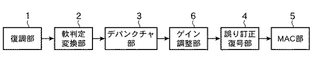
図において、ゲイン調整部6は、誤り訂正における性能を向上させるため、誤り訂正復号部4に入力される軟判定値を最適化した値に調整するために所定の定数を乗算する機能部である。即ち、ゲイン調整部6は、軟判定変換部2から出力される軟判定データとデパンクチャ部3から出力される軟判定データに対して所定の定数を乗算してゲイン調整を行うよう構成されている。これ以外の構成は、実施の形態1と同様であるため、対応する部分に同一符号を付してその説明を省略する。
FIG. 3 is a block diagram showing an error correction decoding apparatus according to
In the figure, a
次に、実施の形態2の誤り訂正復号装置の動作について説明する。
図4は、実施の形態2の動作を示すフローチャートである。
ステップST1〜ステップST3に示す復調部1からデパンクチャ部3までの動作は実施の形態1と同様であるため、ここでの説明は省略する。軟判定変換部2およびデパンクチャ部3から出力された軟判定データはゲイン調整部6に入力され、ゲイン調整部6では、入力された軟判定データのレベルを調整するために定数を乗算しゲイン調整を行う(ステップST11)。このとき、小数点以下の値が生じたときは値を切り上げる。また、誤り訂正復号部4に入力する軟判定ビット数を4ビットとしたときには、ゲイン調整された後の軟判定値が+7より大きな値になった場合は+7にクリップし、−8よりも小さな値になったときは−8にクリップする。
Next, the operation of the error correction decoding apparatus according to the second embodiment will be described.
FIG. 4 is a flowchart showing the operation of the second embodiment.
Since the operations from the demodulating
ゲイン調整を上記のように行うと、ゲイン調整後の軟判定データは、パンクチャビットに関しては0のままであるが、パンクチャされていない受信データの軟判定情報は0以外の値が誤り訂正復号部4に入力されることになる。誤り訂正復号部4では、変換され、ゲイン調整された軟判定データに基づいて、畳み込み復号、あるいはターボ復号処理などの軟判定復号処理を行い(ステップST4a)、復号結果をMAC部5に出力する。
When gain adjustment is performed as described above, the soft decision data after gain adjustment remains 0 with respect to puncture bits, but the soft decision information of received data that has not been punctured has a value other than 0 as an error correction decoding unit. 4 is input. The error
このような構成にすることにより、パンクチャされているビットと実際に受信している軟判定ビットとの間に区別がつく構成となり、また、硬判定結果が誤り訂正復号の演算に反映されるようになり性能向上を図ることができる。 With such a configuration, it is possible to distinguish between punctured bits and actually received soft decision bits, and hard decision results are reflected in the error correction decoding operation. The performance can be improved.
以上のように、実施の形態2の誤り訂正復号装置によれば、軟判定変換部から出力される軟判定データとデパンクチャ部から出力される軟判定データに対して所定の定数を乗算してゲイン調整を行い、誤り訂正復号部に出力するゲイン調整部を備えたので、誤り訂正における性能を向上させることができる。 As described above, according to the error correction decoding apparatus of the second embodiment, the soft decision data output from the soft decision conversion unit and the soft decision data output from the depuncture unit are multiplied by a predetermined constant to gain. Since the gain adjustment unit that performs adjustment and outputs to the error correction decoding unit is provided, the performance in error correction can be improved.
1 復調部、2 軟判定変換部、3 デパンクチャ部、4 誤り訂正復号部、5 MAC部、6 ゲイン調整部。 1 demodulator, 2 soft decision converter, 3 depuncture unit, 4 error correction decoding unit, 5 MAC unit, 6 gain adjustment unit.
Claims (3)
前記復調部から出力される軟判定データのうち、硬判定結果が0の場合は+1以上の軟判定データとし、硬判定結果が1の場合は−1以下の軟判定データを出力する軟判定変換部と、
パンクチャされているデータについては、軟判定データを0とするデパンクチャ部と、
前記軟判定変換部から出力された軟判定データと前記デパンクチャ部から出力された軟判定データとに基づいて誤り訂正復号を行う誤り訂正復号部とを備えた誤り訂正復号装置。 A demodulator that generates soft decision data from the received signal;
Of the soft decision data output from the demodulator, a soft decision conversion that outputs soft decision data of +1 or more when the hard decision result is 0 and outputs soft decision data of -1 or less when the hard decision result is 1 And
For punctured data, a depuncture unit with soft decision data set to 0,
An error correction decoding apparatus comprising: an error correction decoding unit that performs error correction decoding based on soft decision data output from the soft decision conversion unit and soft decision data output from the depuncture unit.
Priority Applications (1)
| Application Number | Priority Date | Filing Date | Title |
|---|---|---|---|
| JP2008041618A JP2009200927A (en) | 2008-02-22 | 2008-02-22 | Error-correcting decoder |
Applications Claiming Priority (1)
| Application Number | Priority Date | Filing Date | Title |
|---|---|---|---|
| JP2008041618A JP2009200927A (en) | 2008-02-22 | 2008-02-22 | Error-correcting decoder |
Publications (1)
| Publication Number | Publication Date |
|---|---|
| JP2009200927A true JP2009200927A (en) | 2009-09-03 |
Family
ID=41143933
Family Applications (1)
| Application Number | Title | Priority Date | Filing Date |
|---|---|---|---|
| JP2008041618A Pending JP2009200927A (en) | 2008-02-22 | 2008-02-22 | Error-correcting decoder |
Country Status (1)
| Country | Link |
|---|---|
| JP (1) | JP2009200927A (en) |
Citations (5)
| Publication number | Priority date | Publication date | Assignee | Title |
|---|---|---|---|---|
| JPS5912646A (en) * | 1982-07-12 | 1984-01-23 | Kokusai Denshin Denwa Co Ltd <Kdd> | Error correcting decoder |
| JP2000004215A (en) * | 1998-06-16 | 2000-01-07 | Matsushita Electric Ind Co Ltd | Transmission/reception system |
| JP2001285084A (en) * | 2000-03-31 | 2001-10-12 | Sony Corp | Device and method for encoding, recording medium with encoding program recorded thereon, device and method for decoding and recording medium with decoding program recorded thereon |
| JP2001523918A (en) * | 1997-11-13 | 2001-11-27 | クゥアルコム・インコーポレイテッド | Method and apparatus for time-efficient retransmission using symbol accumulation |
| WO2006037645A1 (en) * | 2004-10-08 | 2006-04-13 | Telefonaktiebolaget L M Ericsson (Publ) | Puncturing/depuncturing using compressed differential puncturing pattern |
-
2008
- 2008-02-22 JP JP2008041618A patent/JP2009200927A/en active Pending
Patent Citations (5)
| Publication number | Priority date | Publication date | Assignee | Title |
|---|---|---|---|---|
| JPS5912646A (en) * | 1982-07-12 | 1984-01-23 | Kokusai Denshin Denwa Co Ltd <Kdd> | Error correcting decoder |
| JP2001523918A (en) * | 1997-11-13 | 2001-11-27 | クゥアルコム・インコーポレイテッド | Method and apparatus for time-efficient retransmission using symbol accumulation |
| JP2000004215A (en) * | 1998-06-16 | 2000-01-07 | Matsushita Electric Ind Co Ltd | Transmission/reception system |
| JP2001285084A (en) * | 2000-03-31 | 2001-10-12 | Sony Corp | Device and method for encoding, recording medium with encoding program recorded thereon, device and method for decoding and recording medium with decoding program recorded thereon |
| WO2006037645A1 (en) * | 2004-10-08 | 2006-04-13 | Telefonaktiebolaget L M Ericsson (Publ) | Puncturing/depuncturing using compressed differential puncturing pattern |
Similar Documents
| Publication | Publication Date | Title |
|---|---|---|
| JP5122551B2 (en) | Broadcast receiver and method for optimizing the log likelihood mapper scale factor | |
| US7765459B2 (en) | Viterbi decoder and viterbi decoding method | |
| WO2006126501A1 (en) | Reception quality estimating apparatus, wireless communication system, and reception quality estimating method | |
| JPH07312619A (en) | Torerisu decoding method | |
| JP4806642B2 (en) | Viterbi decoding system and Viterbi decoding method | |
| US8250445B2 (en) | Decoding method and error correction method of a cyclic code decoder | |
| US20090327836A1 (en) | Decoding method for convolution code and decoding device | |
| US20050180531A1 (en) | Device for estimating a sequence of N bits corresponding to a received sequence of M digital data and associated method | |
| US7046747B2 (en) | Viterbi decoder and decoding method using rescaled branch metrics in add-compare-select operations | |
| JP2009200927A (en) | Error-correcting decoder | |
| US20070168820A1 (en) | Linear approximation of the max* operation for log-map decoding | |
| JP2008141312A (en) | Encoder, decoder, transmitter, and receiver | |
| US7020223B2 (en) | Viterbi decoder and method using sequential two-way add-compare-select operations | |
| JP4666646B2 (en) | Soft decision Viterbi decoding apparatus and method, decoding apparatus and method | |
| JP5586504B2 (en) | Decoding device | |
| JP2005143106A (en) | Map decoder which is easily embodied, and its decoding method | |
| US20130266096A1 (en) | Viterbi decoder for decoding convolutionally encoded data stream | |
| JP4900388B2 (en) | Multilevel modulation signal receiving method and multilevel modulation signal receiving apparatus | |
| JP4116554B2 (en) | Turbo decoding method and apparatus for wireless communication | |
| JP4528168B2 (en) | Decoder and decoding method | |
| JP4188769B2 (en) | Transmission method and apparatus, reception method and apparatus, and communication system using them | |
| JP5001196B2 (en) | Receiving apparatus and communication system | |
| JP2003264468A (en) | Viterbi decoder | |
| WO2001069796A1 (en) | Viterbi decoder | |
| JP2006173724A (en) | Decoding method and decoding apparatus in trellis or turbo trellis coding modulation system |
Legal Events
| Date | Code | Title | Description |
|---|---|---|---|
| A621 | Written request for application examination |
Effective date: 20101201 Free format text: JAPANESE INTERMEDIATE CODE: A621 |
|
| A977 | Report on retrieval |
Free format text: JAPANESE INTERMEDIATE CODE: A971007 Effective date: 20111031 |
|
| A131 | Notification of reasons for refusal |
Free format text: JAPANESE INTERMEDIATE CODE: A131 Effective date: 20111108 |
|
| A02 | Decision of refusal |
Effective date: 20120313 Free format text: JAPANESE INTERMEDIATE CODE: A02 |