JP2009104236A - Storage apparatus and data storage method using the same - Google Patents
Storage apparatus and data storage method using the same Download PDFInfo
- Publication number
- JP2009104236A JP2009104236A JP2007272900A JP2007272900A JP2009104236A JP 2009104236 A JP2009104236 A JP 2009104236A JP 2007272900 A JP2007272900 A JP 2007272900A JP 2007272900 A JP2007272900 A JP 2007272900A JP 2009104236 A JP2009104236 A JP 2009104236A
- Authority
- JP
- Japan
- Prior art keywords
- data
- volume
- compressed
- disk
- parity
- Prior art date
- Legal status (The legal status is an assumption and is not a legal conclusion. Google has not performed a legal analysis and makes no representation as to the accuracy of the status listed.)
- Granted
Links
Images


Classifications
-
- G—PHYSICS
- G06—COMPUTING; CALCULATING OR COUNTING
- G06F—ELECTRIC DIGITAL DATA PROCESSING
- G06F11/00—Error detection; Error correction; Monitoring
- G06F11/07—Responding to the occurrence of a fault, e.g. fault tolerance
- G06F11/08—Error detection or correction by redundancy in data representation, e.g. by using checking codes
- G06F11/10—Adding special bits or symbols to the coded information, e.g. parity check, casting out 9's or 11's
- G06F11/1076—Parity data used in redundant arrays of independent storages, e.g. in RAID systems
-
- G—PHYSICS
- G06—COMPUTING; CALCULATING OR COUNTING
- G06F—ELECTRIC DIGITAL DATA PROCESSING
- G06F2211/00—Indexing scheme relating to details of data-processing equipment not covered by groups G06F3/00 - G06F13/00
- G06F2211/10—Indexing scheme relating to G06F11/10
- G06F2211/1002—Indexing scheme relating to G06F11/1076
- G06F2211/1009—Cache, i.e. caches used in RAID system with parity
-
- G—PHYSICS
- G06—COMPUTING; CALCULATING OR COUNTING
- G06F—ELECTRIC DIGITAL DATA PROCESSING
- G06F2211/00—Indexing scheme relating to details of data-processing equipment not covered by groups G06F3/00 - G06F13/00
- G06F2211/10—Indexing scheme relating to G06F11/10
- G06F2211/1002—Indexing scheme relating to G06F11/1076
- G06F2211/1014—Compression, i.e. RAID systems with parity using compression techniques
-
- G—PHYSICS
- G06—COMPUTING; CALCULATING OR COUNTING
- G06F—ELECTRIC DIGITAL DATA PROCESSING
- G06F2211/00—Indexing scheme relating to details of data-processing equipment not covered by groups G06F3/00 - G06F13/00
- G06F2211/10—Indexing scheme relating to G06F11/10
- G06F2211/1002—Indexing scheme relating to G06F11/1076
- G06F2211/1059—Parity-single bit-RAID5, i.e. RAID 5 implementations
Landscapes
- Engineering & Computer Science (AREA)
- Theoretical Computer Science (AREA)
- Quality & Reliability (AREA)
- Physics & Mathematics (AREA)
- General Engineering & Computer Science (AREA)
- General Physics & Mathematics (AREA)
- Information Retrieval, Db Structures And Fs Structures Therefor (AREA)
Abstract
Description
本発明は、ストレージ装置及びこれを用いたデータ格納方法に関し、特に、RAID制御の下、書き込みデータを圧縮して効率的に格納するストレージ技術に関する。 The present invention relates to a storage apparatus and a data storage method using the same, and more particularly to a storage technology for efficiently storing write data under RAID control.
ストレージ装置の限られた記憶資源を有効に活用するため、データを圧縮して、格納する技術が知られている。データを圧縮して格納する場合、圧縮後のデータのサイズは不定であり、圧縮前のデータの内容に大きく依存する。 A technique for compressing and storing data in order to effectively use limited storage resources of a storage apparatus is known. When data is compressed and stored, the size of the data after compression is indefinite and greatly depends on the content of the data before compression.
下記特許文献1は、ディスクドライブにデータを圧縮して格納する際に、所定の格納エリアに格納しきれない圧縮データの一部をオーバーフロー用の格納エリアに格納する記憶装置を開示している。具体的には、特許文献1において、主処理装置からのデータをディスクドライブに書き込む場合に、当該データがデータ圧縮手段により圧縮され、書き込み先アドレスに基づいて、圧縮データがディスクドライブ内の固定サイズ格納エリアの該当ブロックに格納できるか否かを判定し、格納できないと判定される場合に、当該圧縮データの一部が該当ブロックに格納されるとともに、当該圧縮データの残りがオーバーフロー部格納エリアに格納される。
また、近年では、大容量かつ高信頼性等の観点から、RAID(Redundant Arrays of Independent Disks)技術を採用したストレージ装置が主流を占めつつある。RAIDには、ハードディスクドライブの構成に応じて、RAIDレベル(RAID0〜6)が定義されている。例えば、RAID1は、複数台のハードディスクドライブに、同時に同じ内容のデータを書き込む(ミラーリング)方式である。また、RAID5は、ブロック単位のデータを複数のハードディスクドライブに誤り訂正符号データ(パリティデータ)とともに分散させて書き込む方式である。
RAID構成は、実用的には、総合的なパフォーマンスに優れたRAID5の構成が主流である。RAID5では、上述したように、耐障害性の観点から、パリティデータが存在する。従って、RAID5の構成の下、書き込みデータを圧縮して格納する場合には、そのパリティデータも圧縮して格納することになる。パリティデータは、書き込みデータに比較してデータビットのランダム性が一般に高い傾向にあり、高い圧縮効率が期待できない。このため、圧縮効率の低下によるデータのオーバーフローが絶えず発生する可能性が高く、単に、従前のオーバーフロー用格納エリアを用意したのでは、すぐに使い切ってしまうおそれがある。また、予め十分なサイズのオーバーフロー用格納エリアを用意したのでは、ランニングコストが高くなり、経済的でない。
As a RAID configuration, a
そこで、本発明は、所定のRAID構成の下で、書き込みデータに基づく圧縮データを効率的に格納することができるストレージ装置を提案することを目的としている。 Accordingly, an object of the present invention is to propose a storage apparatus capable of efficiently storing compressed data based on write data under a predetermined RAID configuration.
具体的には、本発明は、圧縮データが所定の記憶領域に格納しきれない場合に、当該圧縮データのうち格納しきれない分(あふれ分)を、使用実績に応じた柔軟な拡張を可能にする記憶領域(拡張記憶領域)に格納するストレージ装置を提案する。 Specifically, when the compressed data cannot be stored in a predetermined storage area, the present invention can flexibly expand the portion of the compressed data that cannot be stored (overflow) according to the usage record. A storage device that stores data in a storage area (extended storage area) is proposed.
また、本発明は、あるRAID構成の下で、圧縮データの効率的な格納が期待できない場合に、効率的な格納が期待できる他のRAID構成により当該圧縮データを格納するストレージ装置を提案する。つまり、本発明は、パリティデータに対する圧縮効率に応じて、圧縮データを格納する最適なRAID構成を選択するストレージ装置を提案する。 The present invention also proposes a storage apparatus that stores compressed data by another RAID configuration that can be expected to be efficiently stored when efficient storage of the compressed data cannot be expected under a certain RAID configuration. That is, the present invention proposes a storage apparatus that selects an optimal RAID configuration for storing compressed data in accordance with the compression efficiency for parity data.
上記課題を解決するために、本発明に係るストレージ装置は、以下の技術的特徴を含んで構成される。 In order to solve the above problems, a storage apparatus according to the present invention includes the following technical features.
すなわち、第1の観点に従う本発明は、データを格納する記憶媒体を有するディスクデバイスと、前記ディスクデバイスを制御するディスクコントローラと、を備えるストレージ装置である。前記ディスクコントローラは、ホスト装置に接続するためのチャネルアダプタと、前記ディスクデバイスに接続されたディスクアダプタと、前記チャネルアダプタと前記ディスクアダプタとの間でやり取りされるデータを一時的に格納するキャッシュメモリと、を備える。また、前記ディスクアダプタは、前記記憶媒体の固有記憶容量よりも大きな記憶容量が定義され、前記記憶媒体の記憶領域に対応付けられた実ボリューム及び前記実ボリューム以外の記憶領域が割り当てられた仮想ボリュームを含むデータボリュームと、前記仮想ボリュームに割り当てられた記憶領域に対するデータを格納するための記憶領域が割り当てられたプールボリュームとを形成するように、前記ディスクデバイスを制御する。 That is, the present invention according to the first aspect is a storage apparatus including a disk device having a storage medium for storing data, and a disk controller for controlling the disk device. The disk controller includes a channel adapter for connecting to a host device, a disk adapter connected to the disk device, and a cache memory for temporarily storing data exchanged between the channel adapter and the disk adapter. And comprising. In addition, the disk adapter has a storage capacity larger than the specific storage capacity of the storage medium, and a virtual volume to which a storage area other than the real volume and a real volume associated with the storage area of the storage medium are allocated The disk device is controlled to form a data volume including a pool volume to which a storage area for storing data for the storage area assigned to the virtual volume is assigned.
前記ディスクアダプタは、所定のRAID構成による制御の下、前記ホスト装置から送られた書き込み要求に従う書き込みデータに基づいて、当該書き込みデータが属するパリティグループ内のパリティデータを生成し、前記パリティグループ内の前記書き込みデータ及び前記生成されたパリティデータのそれぞれを圧縮して、圧縮データ及び圧縮パリティデータを生成する。また、前記ディスクアダプタは、前記パリティグループ内の前記圧縮データ及び前記圧縮パリティデータのそれぞれが所定のサイズを超えるか否かを判断し、前記圧縮データ及び前記圧縮パリティデータのうち前記所定のサイズを超えない分のデータを前記実ボリュームの記憶領域に格納し、前記圧縮データ及び前記圧縮パリティデータのうち前記所定のサイズを超える分のデータを前記仮想ボリュームに対応する前記プールボリュームの記憶領域に格納する。 The disk adapter generates parity data in a parity group to which the write data belongs based on write data in accordance with a write request sent from the host device under control by a predetermined RAID configuration. Each of the write data and the generated parity data is compressed to generate compressed data and compressed parity data. Further, the disk adapter determines whether or not each of the compressed data and the compressed parity data in the parity group exceeds a predetermined size, and sets the predetermined size of the compressed data and the compressed parity data. Data that does not exceed is stored in the storage area of the real volume, and data that exceeds the predetermined size among the compressed data and the compressed parity data is stored in the storage area of the pool volume corresponding to the virtual volume To do.
また、本発明は、方法の発明として把握することができる。すなわち、第2の観点に従う本発明は、データを格納する記憶媒体を有するディスクデバイスと、前記ディスクデバイスを制御するディスクコントローラと、を備えるストレージ装置におけるデータ格納方法である。 Further, the present invention can be grasped as a method invention. That is, the present invention according to the second aspect is a data storage method in a storage apparatus comprising a disk device having a storage medium for storing data, and a disk controller for controlling the disk device.
前記データ格納方法は、前記ディスクコントローラが、前記記憶媒体の固有記憶容量よりも大きな記憶容量が定義され、前記記憶媒体の記憶領域に対応付けられた実ボリューム及び前記実ボリューム以外の記憶領域が割り当てられた仮想ボリュームを含むデータボリュームと、前記仮想ボリュームに割り当てられた記憶領域に対するデータを格納するための記憶領域が割り当てられたプールボリュームとが形成されるように、前記ディスクデバイスを制御するステップと、前記ディスクコントローラが、所定のRAID構成に従い、前記ホスト装置から送られた書き込み要求に従う書き込みデータに基づいて、当該書き込みデータが属するパリティグループ内のパリティデータを生成するステップと、前記ディスクコントローラが、前記パリティグループ内の前記書き込みデータ及び前記生成されたパリティデータのそれぞれを圧縮して、圧縮データ及び圧縮パリティデータを生成するステップと、前記ディスクコントローラが、前記パリティグループ内の前記圧縮データ及び前記圧縮パリティデータのそれぞれが所定のサイズを超えるか否かを判断するステップと、前記ディスクコントローラが、前記圧縮データ及び前記圧縮パリティデータのうち前記所定のサイズを超えない分のデータを前記実ボリュームの記憶領域に格納するとともに、前記圧縮データ及び前記圧縮パリティデータのうち前記所定のサイズを超える分のデータを前記仮想ボリュームに対応する前記プールボリュームの記憶領域に格納するステップと、を含む。 In the data storage method, the disk controller defines a storage capacity larger than the specific storage capacity of the storage medium, and allocates a real volume associated with the storage area of the storage medium and a storage area other than the real volume. Controlling the disk device so that a data volume including the assigned virtual volume and a pool volume to which a storage area for storing data for the storage area assigned to the virtual volume is assigned are formed. The disk controller generates parity data in a parity group to which the write data belongs based on write data in accordance with a write request sent from the host device according to a predetermined RAID configuration; Paris Compressing each of the write data and the generated parity data in a storage group to generate compressed data and compressed parity data, and the disk controller comprising the compressed data and compressed parity in the parity group A step of determining whether each of the data exceeds a predetermined size; and the disk controller stores the data of the compressed data and the compressed parity data that do not exceed the predetermined size in the storage area of the real volume And storing in the storage area of the pool volume corresponding to the virtual volume the data exceeding the predetermined size among the compressed data and the compressed parity data.
本発明によれば、所定のRAID構成の下で、書き込み圧縮データに基づく圧縮データを効率的に格納することができるようになる。 According to the present invention, compressed data based on write compressed data can be efficiently stored under a predetermined RAID configuration.
また、本発明によれば、圧縮データが所定の記憶領域に格納しきれない場合に、拡張記憶領域に格納しているので、記憶領域の使用実績に応じた柔軟なディスクデバイスの構成を採用することができるようになる。 In addition, according to the present invention, when the compressed data cannot be stored in the predetermined storage area, it is stored in the extended storage area. Therefore, a flexible disk device configuration corresponding to the use record of the storage area is adopted. Will be able to.
さらに、本発明によれば、パリティを含むデータに対する圧縮効率に応じて最適なRAID構成を選択するので、圧縮データの効率的な格納ができるようになる。 Furthermore, according to the present invention, since an optimal RAID configuration is selected according to the compression efficiency for data including parity, compressed data can be efficiently stored.
次に、本発明の実施の形態について、図面を参照しつつ説明する。
[第1の実施形態]
Next, embodiments of the present invention will be described with reference to the drawings.
[First Embodiment]
第1の実施形態では、RAID5の構成の下、書き込みデータを圧縮し、当該圧縮されたデータをデータボリューム上の実記憶領域に格納しきれない場合に、当該格納しきれない分を、ボリューム容量仮想化機能により提供される拡張記憶領域に格納するように構成されたストレージ装置が説明される。
In the first embodiment, when the write data is compressed under the configuration of
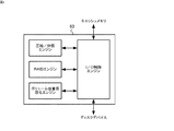
図1は、本発明の一実施形態に係るストレージシステムの構成を説明するための図である。同図に示すように、コンピュータシステム1は、ネットワーク2を介してホスト装置3に接続されたストレージ装置4を含んで構成されている。
FIG. 1 is a diagram for explaining the configuration of a storage system according to an embodiment of the present invention. As shown in the figure, the
ネットワーク2は、例えばLAN、インターネット、又はSAN(Storage Area Network)であり、ネットワークスイッチやハブ等を含んで構成される。本実施形態では、ネットワーク2は、ファイバーチャネルプロトコルを用いたSAN(FC−SAN)で構成されているものとする。
The
ホスト装置3は、例えば銀行の業務システムや航空機の座席予約業務システム等における中核をなすコンピュータである。ホスト装置3は、プロセッサと、メインメモリと、通信インターフェースと、ローカル入出力装置等のハードウェア資源を備え、また、デバイスドライバやオペレーティングシステム(OS)、アプリケーションプログラム等のソフトウェア資源を備えている(図示せず)。これによって、ホスト装置3は、プロセッサの制御の下、各種のプログラムを実行して、ハードウェア資源との協働作用により、所望の処理を実現する。例えば、ホスト装置3は、プロセッサの制御の下、業務アプリケーションプログラムを実行することにより、以下に詳述されるストレージ装置4にアクセスし、所望の業務システムを実現する。
The
ストレージ装置4は、データストレージサービスをホスト装置3に提供する補助記憶装置である。ストレージ装置4は、データを格納するディスクデバイス5と、ディスクデバイス5の構成を管理して、それに対する書き込み又は読み出しといったI/O処理を制御するディスクコントローラ6と、を備える。ストレージ装置4はまた、ストレージ装置4全体を管理するための管理装置乃至はサービスプロセッサ(図示せず)を含むことができる。あるいは、ディスクコントローラ6が管理装置の機能を含むように、ディスクコントローラ6を構成してもよい。管理装置は、例えば、管理プログラムが実装された汎用コンピュータである。
The
本実施形態のストレージ装置4は、後述するように、RAID制御の下、書き込みデータを圧縮し、その圧縮データをディスクデバイス5の所定の記憶領域に格納する。ストレージ装置4は、圧縮データが所定のブロックサイズを超える場合には、当該超えた分を拡張記憶領域(プールボリューム)に格納する。プールボリュームは、後述するように、ボリューム容量仮想化機能により提供される仮想ボリュームに対応付けられた、データの実体を格納する論理ボリュームである。
As will be described later, the
ディスクデバイス5は、例えば複数のハードディスクドライブ(HDD)や半導体メモリ等の記憶媒体を含んで構成される物理デバイス(PDEV)である。複数のハードディスクの集合体をディスクアレイと呼ぶこともある。ディスクデバイス5には、ディスクコントローラ6の制御の下、ホスト装置3に提供するための1つ以上の論理デバイス(LDEV)が形成される。論理デバイスは、いくつかのハードディスクドライブを仮想的に1つのデバイスにまとめた仮想デバイスVDEVに対して形成されてもよい。
The
論理デバイスは、ホスト装置3が認識しうる論理的な記憶装置である。論理デバイスには、論理ユニット(LU)が割り当てられてもよい。この場合、各論理デバイスは、後述するチャネルアダプタ61に設けられた各ポートに割り当てられ、これにより、ホスト装置3は、論理デバイスを論理ユニットとして認識する。各論理ユニットには、論理ユニット番号(LUN)が付与される。また、論理ユニットは、I/Oアクセスの最小単位であるブロックに分割され、各ブロックには、論理ブロックアドレス(LBA)が割り当てられる。これにより、ホスト装置3は、LUNおよびLBAからなる論理アドレスをストレージ装置4に与えることにより、特定の論理ユニットにおける任意のブロックに記憶されたデータに対してアクセスを行うことができる。論理デバイス及び論理ユニットは、ストレージ装置4が適用されるシステム環境により区別されうるが、本発明では両者を同義に扱うことができる。
The logical device is a logical storage device that can be recognized by the
論理デバイスには、属性に応じた論理ボリューム(LVOLまたはVOL)が定義される。ただし、慣用的に両者は同義に扱われることもある。本実施形態では、論理ボリュームとして、データボリューム及びプールボリュームが定義される。後述するように、データボリュームは、実ボリューム及び仮想ボリュームを含んでいる。 A logical volume (LVOL or VOL) corresponding to the attribute is defined in the logical device. However, both are sometimes treated synonymously. In this embodiment, a data volume and a pool volume are defined as logical volumes. As will be described later, the data volume includes a real volume and a virtual volume.
ディスクコントローラ6は、チャネルアダプタ(CHA)61と、キャッシュメモリ(CM)62と、ディスクアダプタ(DKA)63と、共有メモリ(SM)64と、を備え、これらのコンポーネントは、内部スイッチ(SW)65を介して相互に接続されている。これらのコンポーネントは、高速性、耐障害性の観点等の観点から、多重化されることが望ましい。
The
ディスクコントローラ6は、ディスクデバイス5を制御して、データストレージサービスを実現するストレージ装置4のメインシステムボードである。本実施形態のディスクコントローラ6は、ホスト装置3からのI/Oアクセス要求に基づく通常のI/O処理機能に加え、データ圧縮/伸張機能、RAID機能、及びボリューム容量仮想化機能を実現する構成を含んでいる。
The
チャネルアダプタ61は、ネットワーク2を介してストレージ装置4をホスト装置3に通信可能に接続するためのコンポーネントである。本例では、2つのチャネルアダプタ61が搭載されている。各チャネルアダプタ61は、マイクロプロセッサ611と、ローカルメモリ612と、通信インターフェース(I/F)613と、I/Oプロセッサ614と、を備える。
The
マイクロプロセッサ611は、ローカルメモリ612に格納されたマイクロプログラムを実行することにより、チャネルアダプタ61の動作を統括的に制御するチップ回路である。通信I/F613は、ネットワーク2から通信パケット乃至はフレームを取り込み、または、ネットワーク2に通信パケットを送出する。通信I/F613は、ネットワーク2に接続するための複数のポートを備える(図示せず)。I/Oプロセッサ614は、内部スイッチ65を介して接続されるディスクコントローラ6内の他のコンポーネント(例えば、キャッシュメモリ62や共有メモリ64)との間でデータの授受を制御する。
The
具体的には、マイクロプロセッサ611は、通信I/F613を介してパケットを受け取ると、所定のプロトコルに応じたプロトコル変換処理を行って、内部データを取り出す。続いて、マイクロプロセッサ611は、当該内部データを解釈して、これが書き込みコマンドであれば、当該書き込みコマンドを共有メモリ64に、その書き込みデータ(すなわちユーザデータ)をキャッシュメモリ62に書き込むように、I/Oプロセッサ614を制御する。I/Oプロセッサ614は、これを受けて、書き込みコマンドを共有メモリ64に書き込むとともに、その書き込みデータをキャッシュメモリ62に書き込む。
Specifically, when receiving a packet via the communication I / F 613, the
また、マイクロプロセッサ611は、読み出しコマンドに従って、I/Oプロセッサ614を介して読み出しデータをキャッシュメモリ62から取り出して、所定のプロトコルに応じたプロトコル変換処理を行ってパケットを生成し、通信I/F613を介してネットワーク2に送出する。
Further, the
キャッシュメモリ62は、ホスト装置3に対して高いシステムパフォーマンスを提供するため、ホスト装置3とディスクデバイス5(論理ボリューム)との間でやり取りされるユーザデータを一時的に記憶(キャッシュ)する。つまり、キャッシュメモリ62は、チャネルアダプタ61とディスクアダプタ63との間のデータの受け渡しに利用されるメモリである。キャッシュメモリ62は、例えば、DRAM等の揮発性メモリで構成される。あるいは、キャッシュメモリ62は、フラッシュメモリ等の不揮発性メモリで構成されるかも知れない。
The
キャッシュメモリ62はまた、後述するように、圧縮された書き込みデータ(圧縮データ)を一時的に記憶するメモリとしても利用される。データ圧縮/伸張処理は、例えば、ディスクアダプタ63によって行われる。
The
ディスクアダプタ63は、ディスクチャネルを介して接続されたディスクデバイス5に対するI/Oアクセスを行うコンポーネントである。本例では、2つのディスクアダプタ63が搭載されている。各ディスクダプタ63は、マイクロプロセッサ631と、ローカルメモリ632と、ディスクインターフェース(I/F)633と、I/Oプロセッサ634と、を備える。本実施形態では、ディスクアダプタ63は、I/O制御機能、データ圧縮/伸張機能、RAID機能、及びボリューム容量仮想化機能を実装している。これらの機能は、例えば、図2に示すようなファームウェアとして実現される。
The
マイクロプロセッサ631は、ローカルメモリ632に格納されたマイクロプログラムを実行することにより、ディスクアダプタ63の動作を統括的に制御するチップ回路である。本実施形態では、マイクロプロセッサ631は、RAID制御の下、キャッシュメモリ62に格納された書き込みデータに対して所定の圧縮アルゴリズムに従った圧縮処理を行って圧縮データを生成し、これをディスクデバイス5の所定の記憶領域に書き込む。ここでいう所定の記憶領域とは、実ボリューム上の記憶領域(実記憶領域)である。圧縮データのうち当該実記憶領域に格納しきれない分のデータは、ボリューム容量仮想化機能により管理される拡張記憶領域(プールボリューム)に格納される。圧縮/伸張アルゴリズムは、例えば、LZW方式等の既知のアルゴリズムを適用することができる。
The
ディスクI/F633は、物理デバイスとしてのディスクデバイス5にI/Oアクセスを行うためのインターフェースである。I/Oプロセッサ634は、内部スイッチ65を介して接続される他のコンポーネント(例えばキャッシュメモリ62や共有メモリ64)との間のデータの授受を制御する。
The disk I /
より具体的には、マイクロプロセッサ631は、定期的(例えば数十msおき)又は不定期に、I/Oプロセッサ634を介して共有メモリ64を参照する。マイクロプロセッサ631は、共有メモリ64上の未処理の書き込みコマンドを見つけると、キャッシュメモリ62から対応する書き込みデータを取り出して、RAID制御の下で、圧縮処理を行い、圧縮データを生成する。つまり、書き込みデータに基づくパリティデータが生成され、このパリティデータを含む書き込みデータに対する圧縮データが生成される。圧縮データは、キャッシュメモリ62上の圧縮データ用ブロックに、再度、格納される。そして、マイクロプロセッサ631は、生成した圧縮データを、RAID制御の下で、データボリュームを形成しているディスクデバイス5上の所定の記憶領域(ブロック)に格納(デステージング)する。例えばRAID5(3D+1P)の構成にあれば、圧縮データは、そのパリティデータとともに、物理的に異なる系列のディスクデバイス5に分散されて格納される。また、このとき、マイクロプロセッサ63は、生成された圧縮データをデータボリュームにおいて規定される実記憶領域に格納しきれるか否かを判断し、格納しきれないと判断する場合には、当該圧縮データのうち格納しきれない分のデータを、ボリューム容量仮想化機能により管理される拡張記憶領域に格納する。
More specifically, the
また、マイクロプロセッサ631は、共有メモリ64上の読み出しコマンドに従い、RAID制御の下、所定の論理ボリュームから圧縮データを読み出して、キャッシュメモリ62に、一旦、格納する。そして、マイクロプロセッサ631は、伸張処理を行い、得られた伸張データ(元のデータ)をキャッシュメモリ522に、再度、書き込む(ステージング)。圧縮データの一部が拡張記憶領域に格納されている場合には、マイクロプロセッサ631は、適宜、拡張記憶領域から当該部分的な圧縮データを読み出し、一つの圧縮データに統合する。
Further, the
共有メモリ64は、ストレージ装置4内の各コンポーネントが参照すべき各種の情報を記憶する。共有メモリ64は、例えばDRAM等の揮発性メモリで構成される。
The shared
内部スイッチ65は、クロスバースイッチ等により構成されるスイッチングデバイスである。内部スイッチ428は、入力されるデータ信号の競合を調停し、データ信号のパスを切り替えて、送出元のモジュールと送出先のモジュールとのパスを構築する。なお、内部スイッチ428は、パケット交換方式のスイッチングデバイスであってもよい。
The
図3は、本発明の一実施形態に係るストレージ装置4における共有メモリ64の内容を示す図である。同図に示すように、共有メモリ63は、例えば、システム構成情報、キャッシュ管理テーブル、データブロック管理テーブル、物理デバイス管理テーブル等の各種の情報を記憶する。
FIG. 3 is a diagram showing the contents of the shared
システム構成情報は、ディスクデバイス5の構成情報やストレージ装置4内の各コンポーネント上で動作するマイクロプログラムのバージョン情報といったシステムの構成に関する情報である。ディスクデバイス5の構成情報としては、例えば、RAID構成情報、物理デバイス/論理デバイス(ボリューム)の構成情報、ボリューム容量仮想化構成情報を含む。物理デバイス/論理デバイス構成情報は、例えば、セグメント管理テーブル及びアドレス管理テーブルとして定義される。また、ボリューム容量仮想化構成情報は、例えば、プールボリューム管理テーブルを含む。
The system configuration information is information relating to the configuration of the system, such as configuration information of the
システム構成情報は、システム管理者が操作する管理装置によって、設定・管理される。例えば、システム管理者は、管理装置を操作して、RAID5(3D+1P)の構成を設定することができる。また、システム管理者は、ハードディスクドライブの増設に併せて、管理装置を操作して、ボリューム容量仮想化構成情報を設定する。 System configuration information is set and managed by a management device operated by a system administrator. For example, the system administrator can set the configuration of RAID 5 (3D + 1P) by operating the management apparatus. Further, the system administrator sets the volume capacity virtualization configuration information by operating the management apparatus in conjunction with the addition of the hard disk drive.
キャッシュ管理テーブルは、キャッシュメモリ62にキャッシュされたデータのディレクトリ情報を管理するテーブルである。キャッシュ管理テーブルは、書き込みデータを構成するデータブロックのそれぞれがディスクデバイス5(論理ボリューム)上のどのブロックに対応するかを管理する。
The cache management table is a table that manages directory information of data cached in the
上述したように、本実施形態では、論理ボリューム(データボリューム)には、書き込みデータそのものではなく、その圧縮データが格納される。従って、データボリューム上に上に規定された記憶領域のブロックサイズは、典型的には、平均的な圧縮率を考慮して、キャッシュメモリ62上に規定されたブロックサイズよりも小さく規定されている。また、ディスクアダプタ63は、キャッシュメモリ62の所定のブロックから読み出して圧縮したデータを、再度、キャッシュメモリ62の別のブロック(圧縮データ用ブロック)に格納してから、デステージングしている。このため、キャッシュ管理テーブルは、キャッシュメモリ62上のRAW状態の書き込みデータ及び圧縮データの各論理アドレスと、データボリューム上の論理アドレスとを対応付けている。
As described above, in this embodiment, the logical volume (data volume) stores not the write data itself but the compressed data. Therefore, the block size of the storage area defined above on the data volume is typically defined smaller than the block size defined on the
データブロック管理テーブルは、RAID制御によるパリティグループごとのデータブロックを管理するためのテーブルである。パリティグループとは、本明細書では、同時並列的にアレイディスクに書き込まれるデータブロック群を指している。例えば、RAID5(3D+1P)であれば、3つのデータブロックと1つのパリティブロックからなるデータブロック群が同一のパリティグループに属する。 The data block management table is a table for managing data blocks for each parity group by RAID control. In this specification, a parity group refers to a group of data blocks written to an array disk in parallel at the same time. For example, in the case of RAID5 (3D + 1P), a data block group including three data blocks and one parity block belongs to the same parity group.
ディスクデバイス管理テーブルは、RAID制御の下でデータボリュームを形成するストライプ構成された(すなわち、物理的に異なる系列として構成された)「ディスクデバイス」のアドレス空間の使用状況を管理するためのテーブルである。ディスクデバイス管理テーブルは、ストライプ構成数だけ用意される。例えば、RAID5(3D+1P)であれば、4つのディスクデバイス管理テーブルが用意される。なお、慣用的なRAIDの説明に従えば、ストライプ構成されたディスクデバイスは、個々の物理デバイスに等しく考えることができる。しかしながら、本実施形態では、ストライプ構成された「ディスクデバイス」は、ボリューム容量仮想化機能により物理記憶領域を持たない仮想ボリュームを含む概念で説明される。従って、本明細書では、RAID制御の下でストライプ構成された個々のディスクデバイスを「疑似ディスクデバイス」と呼ぶことにする。RAID5(3D+1P)であれば、あるデータボリュームは、4つの疑似ディスクデバイス上に形成される。 The disk device management table is a table for managing the usage status of the address space of “disk devices” configured in stripes (that is, configured as physically different series) forming a data volume under RAID control. is there. There are as many disk device management tables as the number of stripe configurations. For example, for RAID 5 (3D + 1P), four disk device management tables are prepared. According to the conventional RAID description, a disk device having a stripe configuration can be considered as an individual physical device. However, in the present embodiment, the “disk device” configured as a stripe is described based on the concept including a virtual volume having no physical storage area by the volume capacity virtualization function. Therefore, in this specification, individual disk devices configured in stripes under RAID control are referred to as “pseudo disk devices”. In the case of RAID 5 (3D + 1P), a data volume is formed on four pseudo disk devices.
図4は、本発明の一実施形態に係るストレージ装置4におけるセグメント管理テーブルの一例を示している。セグメント管理テーブルは、ストレージ装置4が提供する論理ボリューム上の記憶領域空間を管理するためのテーブルである。同図に示すように、セグメント管理テーブルは、ディスクIDと、セグメント番号と、LBA開始アドレスと、LBA終了アドレスと、セグメントの使用状況とを含む。
FIG. 4 shows an example of the segment management table in the
ディスクIDは、ディスクデバイス5を構成する物理デバイスを一意に識別するための識別子である。セグメント番号は、セグメントを一意に識別するための番号である。セグメントは、ディスクコントローラ6が管理するディスクデバイス5上の記憶領域である。LBA開始アドレス及びLBA終了アドレスは、ディスクデバイス5上のセグメントの物理的な開始位置及び終了位置を示すアドレスである。LBA開始アドレス及びLBA終了アドレスより、セグメントの大きさが求められる。使用状況は、セグメントが使用されているか否かを示す。セグメントが使用中の場合は“1”、未使用の場合は“0”の値が設定される。
The disk ID is an identifier for uniquely identifying the physical device that constitutes the
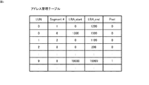
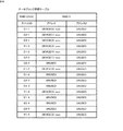
図5は、本発明の一実施形態に係るストレージ装置4の共有メモリ64に格納されたアドレス管理テーブルの一例を示している。アドレス管理テーブルは、ストレージ装置4が提供する論理ボリューム上の記憶領域(すなわち、論理アドレス空間)とディスクデバイス5上の実際の記憶領域(すなわち、物理アドレス空間)とを対応付けるテーブルである。ディスクアダプタ63は、アドレス管理テーブルを参照することによって、データの格納先として指定された論理アドレスを、ディスクデバイス5上の物理アドレスに変換し、その物理アドレスに従ってアクセスを行う。また、アドレス管理テーブルは、論理ボリュームのうち、プールボリュームとして使用されるセグメントを定義する。
FIG. 5 shows an example of an address management table stored in the shared
すなわち、同図に示すように、アドレス管理テーブルは、論理ユニット番号(LUN)、セグメント番号、LBA開始アドレス、LBA終了アドレス、及びプール割り当て状況を含む。論理ユニット番号は、ストレージ装置4がホスト装置3に提供する論理ボリュームを一意に識別するための番号である。セグメント番号は、セグメント管理テーブルにおいて管理されている記憶領域を一意に識別するための番号である。論理ボリュームLUは、複数のセグメントから構成される。LBA開始アドレス及びLBA終了アドレスは、セグメントの論理的な開始アドレス及び終了アドレスを示す。プール割り当て状況は、そのセグメントがプールボリュームとして使用されるか否かを示す。セグメントがプールボリュームとして使用される場合には、“1”が書き込まれる。
That is, as shown in the figure, the address management table includes a logical unit number (LUN), a segment number, an LBA start address, an LBA end address, and a pool allocation status. The logical unit number is a number for uniquely identifying the logical volume that the
図6は、本発明の一実施形態に係るストレージ装置4の共有メモリ64に格納されたデータボリュームを説明するための図である。同図に示すように、データボリュームDVOL0は、0〜99999の論理アドレス空間を有し、第1のディスクデバイス及び第2のディスクデバイスにおけるそれぞれのセグメントが割り当てられている。第1のディスクデバイス5は、図4に示されたように、ディスクID「0」が割り当てられた物理デバイスであり、第2のディスクデバイス5は、ディスクID「1」が割り当てられた物理デバイスである。また、図5に示されるように、セグメント番号「1」で示されるセグメントは、データボリュームDVOL0上の0〜1299の論理アドレス空間を提供する。また、セグメント番号「3」で示されるセグメントは、1300〜1999の論理アドレス空間を提供する。このようにして、データボリュームDVOL0は、あたかも1つのディスクデバイスのように扱われる。
FIG. 6 is a diagram for explaining a data volume stored in the shared
データボリュームDVOL0の論理アドレス空間2000〜99999は、物理デバイスとしてのディスクデバイスが割り当てられていない。ディスクコントローラ6は、データボリュームDVOL0のその空間に対しても、見かけ上、データを格納する。このため、ストレージ装置4は、プールボリュームPVOLと呼ばれる論理ボリュームをさらに備え、データボリュームDVOL0内の記憶領域であって、ディスクデバイス5上のセグメントが割り当てられていない記憶領域(拡張記憶領域)に対して格納されるべきデータを、このプールボリュームPVOLに格納する。つまり、データボリュームDVOL0の論理アドレス空間2000〜49999に格納されるデータの実体は、プールボリュームPVOLに格納されることになる。このため、データボリュームの拡張記憶領域に対するアクセスは、内部的には、プールボリューム管理テーブルに従って、プールボリュームPVOLに対して行われることになる。拡張記憶領域に格納されるべきデータは、物理デバイスにより実際に提供される記憶領域(実記憶領域)に格納しきれない圧縮されたデータブロックである。
In the
同図は、ボリューム容量仮想化機能を適用されたデータボリュームDVOLを簡略的に説明している。本実施形態では、ディスクデバイス5は、RAID構成に応じてストライプ構成される。従って、データボリュームDVOLは、実際は、物理的に異なる系列の4つの疑似ディスクデバイスによって提供される。
This figure briefly explains the data volume DVOL to which the volume capacity virtualization function is applied. In the present embodiment, the
図7は、本発明の一実施形態に係るストレージ装置4における記憶領域の動的割り当てを概念的に説明するための図である。
FIG. 7 is a diagram for conceptually explaining dynamic allocation of storage areas in the
上述したように、本実施形態に係るストレージ装置4のディスクデバイス5には、データボリュームDVOL及びプールボリュームPVOLが形成される。データボリュームDVOLは、ホスト装置3に提供される論理ボリュームである。データボリュームDVOLは、実際に実装されているディスクデバイス5を構成する物理デバイスの固有記憶容量に依存して、実ボリュームと仮想ボリュームとに分けられている。つまり、実ボリュームは、ディスクデバイス5を構成する物理デバイスにより実際に提供されるセグメント上に形成された物理的な記憶領域を含む。これに対して、仮想ボリュームは、実際に提供されるセグメント以外の仮想的な記憶領域(拡張記憶領域)に対応する。従って、仮想ボリュームには、データの実体が格納されない。プールボリュームPVOLは、仮想ボリュームに格納されるべきデータの実体を、将来的にディスクデバイスが追加的に実装され物理的な記憶領域が確保されて新たなデータボリュームDVOLが定義されるまでの間、一時的に格納する記憶領域を提供する論理ボリュームである。
As described above, the data volume DVOL and the pool volume PVOL are formed in the
ストレージ装置4は、データボリュームVOLにおける実ボリューム上の記憶領域に対しては、ホスト装置2が認識する論理アドレス(LUNおよびLBA)と、ディスクデバイス5における記憶領域上の物理アドレスとを一対一に関連付けている。これによって、ホスト装置2は、所定の論理アドレスを指定することによって、ディスクデバイス5上の所望の記憶領域にアクセスすることができる。
The
一方、プールボリュームPVOL上の記憶領域については、ホスト装置3が認識する論理アドレスと、実際にデータにアクセスするためのディスクデバイス5上の物理アドレスとを直接的に関連付けていない。ディスクアダプタ63は、データボリュームDVOLにおける仮想ボリューム上の記憶領域を指定したデータの書き込み命令に従い、当該記憶領域をプールボリュームPVOLに動的に割り当てる。また、ディスクアダプタ63は、データボリュームDVOLにおける仮想ボリューム上の記憶領域からの読み出し命令に従い、プールボリュームPVOL上の当該記憶領域からデータを読み出す。
On the other hand, for the storage area on the pool volume PVOL, the logical address recognized by the
このように、ストレージ装置4は、プールボリューム管理テーブルを保持し、仮想ボリュームとプールボリュームとの間の動的な割り当てを管理している。プールボリューム管理テーブルは、例えば、ディスクコントローラ6の共有メモリ64に保持される。ストレージ装置4は、圧縮データを実ボリュームに格納しきれない場合には、当該格納しきれない分を、プールボリュームPVOLに格納するとともに、仮想ボリューム上の論理アドレスとプールボリュームのアドレスを示すポインタとを関連付けて、プールボリューム管理テーブルに登録する。
Thus, the
図8は、本発明の一実施形態に係るストレージ装置4における共有メモリ64に格納されたデータブロック管理テーブルの一例を示す図である。同図に示すように、データブロック管理テーブルは、スロットIDとデータボリューム内のアドレスとを対応付けている。スロットIDは、パリティグループ内のデータブロックを識別するための識別子である。これにより、データブロック管理テーブルは、パリティグループ内のデータブロックが、どの物理デバイスのどのアドレスに格納されるかを管理する。
FIG. 8 is a diagram showing an example of a data block management table stored in the shared
図9は、本発明の一実施形態に係るストレージ装置4における共有メモリ64に格納されたディスクデバイス管理テーブルの一例を示す図である。同図に示すように、ディスクデバイス管理テーブルは、各疑似ディスクデバイス内の個々のアドレスで示される記憶領域とそこに格納されているデータブロック(スロット識別子)とを対応付けている。また、ディスクデバイス管理テーブルは、拡張記憶領域における使用状況を管理している。本例は、疑似ディスクデバイス(0)に対応するディスクデバイス管理テーブルを示している。すなわち、同図のディスクデバイス管理テーブルは、アドレス“xxxx”で示される記憶領域には“D1−1”が格納され、拡張記憶領域1には“D1−2”が格納されていることを示している。また、拡張記憶領域2は使用可能であることを示している。さらに、拡張記憶領域nは、まだ、実際の記憶領域が割り当てられていないことを示している。
FIG. 9 is a diagram showing an example of a disk device management table stored in the shared
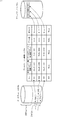
図10及び図11は、本発明の一実施形態に係るストレージ装置4におけるデータ書き込みメカニズムを説明するための図である。具体的には、これらの図は、ある書き込みデータが圧縮された後、RAID5(3D+1P)の下で、異なる系列の疑似ディスクデバイスに格納される様子を示している。
10 and 11 are diagrams for explaining a data write mechanism in the
データボリュームに対する書き込みデータは、ストレージ装置4内部で、ブロック化されたデータ(データブロック)として扱われる。単位ブロックのサイズは、例えば64KBである。本実施形態では、書き込みデータは圧縮されて格納されるため、データボリューム上では、当該サイズよりも小さなサイズ(例えば、16KB)の単位記憶領域が規定される。キャッシュメモリ62上の64KBの各ブロックは、データボリューム上の16KBの各ブロックに対応付けられている。従って、64KBのデータが圧縮されたときに、その圧縮データが16KBを超えなければ、キャッシュメモリ62上の64KBブロックに対応付けられたデータボリューム上の16KBブロック(基本ブロック)に収容できるが、その圧縮データが16KBを超える場合には、当該16KBブロック以外の予備ブロックが必要になる。つまり、64KB×1データブロックの圧縮データが16KB×3データブロックで構成される場合、超過分の2データブロックは、予備的なブロックに格納されることになる。
Write data to the data volume is handled as block data (data block) in the
今、あるデータボリュームに対するデータD1の書き込み要求があったとする。説明を簡略化するために、書き込みデータD1は、ブロックサイズが64KBである単一のデータブロックであるとする。RAID制御の下、書き込みデータD1をデータボリュームに格納するためには、同一のパリティグループ内のデータブロックD2及びD3とともにパリティを算出して、これらを格納する必要がある(図10(A))。 Assume that there is a request to write data D1 to a certain data volume. To simplify the description, it is assumed that the write data D1 is a single data block having a block size of 64 KB. In order to store the write data D1 in the data volume under RAID control, it is necessary to calculate the parity together with the data blocks D2 and D3 in the same parity group and store them (FIG. 10A). .
データブロックD1〜D3は、ディスクアダプタ63の制御の下、圧縮され、図10(B)に示すような圧縮データブロックが得られたとする。圧縮データブロックの単位サイズは16KBである。すなわち、圧縮前のデータブロックD1は、圧縮データブロックD1−1及びD1−2となり、圧縮前のデータブロックD2は、圧縮データブロックD2−1及びD2−2となり、そして、圧縮前のデータブロックD3は、圧縮データブロックD3−1となったとする。また、これら圧縮前データブロックD1〜D3のパリティデータPは、圧縮データブロックP1−1〜P−4に変換されたとする。つまり、圧縮データブロックD1−2、D2−2、及びP−2〜P−4は、データボリューム上の基本ブロックに格納しきれないデータブロックである。
The data blocks D1 to D3 are compressed under the control of the
本実施形態では、キャッシュメモリ62上の64KBブロックは、データボリューム上の16KB基本ブロックに関連付けられている。基本ブロックは、データボリュームの実ボリュームにおける記憶領域(実記憶領域)である。また、データの内容によっては、その圧縮データを実記憶領域に格納しきれない場合があるため、当該格納しきれない分のデータブロックは、仮想ボリュームのブロック(拡張記憶領域)に格納する。
In the present embodiment, the 64 KB block on the
すなわち、図11に示すように、圧縮データブロックD1−1、D2−1、D3−1、及びP−1は、RAID制御の下、データボリュームを構成するRAIDグループにおける疑似ディスクデバイス(0)〜疑似ディスクデバイス(3)上の実ボリュームにおけるブロック(実記憶領域)にそれぞれ格納される。また、圧縮データブロックD1−2、D2−2、及びP−2〜P−4は、当該RAIDグループにおける対応する疑似ディスクデバイス(0)〜疑似ディスクデバイス(4)上の仮想ボリュームにおけるブロック(拡張記憶領域)にそれぞれ格納される。ただし、上述したように、仮想ボリュームは、データの実体を格納する物理デバイスのセグメントが割り当てられていない。従って、仮想ボリュームに格納されるデータの実体は、プールボリュームに格納されることになる。 That is, as shown in FIG. 11, the compressed data blocks D1-1, D2-1, D3-1, and P-1 are the pseudo disk devices (0) to (0) in the RAID group constituting the data volume under RAID control. They are respectively stored in blocks (real storage areas) in the real volume on the pseudo disk device (3). The compressed data blocks D1-2, D2-2, and P-2 to P-4 are blocks (expansion) in the corresponding virtual disk device (0) to pseudo disk device (4) in the RAID group. Stored in a storage area). However, as described above, the virtual volume is not allocated with the segment of the physical device that stores the data entity. Therefore, the substance of data stored in the virtual volume is stored in the pool volume.
図12は、本発明の一実施形態に係るストレージ装置4におけるデータ書き込み処理を説明するためのフローチャートである。具体的には、同図は、データ書き込み処理時におけるディスクアダプタ63の動作を説明している。
FIG. 12 is a flowchart for explaining data write processing in the
すなわち、ディスクアダプタ63は、共有メモリ64を参照し、未処理の書き込みコマンドを見つけると、キャッシュメモリ62上のそれに対応する書き込みデータを特定する。ディスクアダプタ63は、当該書き込みデータに基づいて、RAID構成に従ったパリティデータを生成する(STEP1201)。つまり、本例では、ディスクアダプタ63は、RAID5(3D+1P)の構成に従い、3つのデータブロックごとに1つのパリティデータブロックを生成する。これら3つのデータブロックと1つのパリティデータブロックにより1つのパリティグループが形成される。従って、1つのデータブロックの書き込みであっても、パリティグループ内の残りの2つのデータブロックとともに新しいパリティデータブロックを生成する必要がある。これは一般に「ライトペナルティ」と呼ばれている。このフェーズでは、各データブロックは、64KBのブロックサイズである。
That is, when the
続いて、ディスクアダプタ63は、当該パリティグループにおける各データブロック(パリティデータブロックを含む。)に対して圧縮処理を行って、圧縮データ列をそれぞれ生成する(STEP1202)。圧縮データ列は、1以上のデータブロック(圧縮データブロック)から構成される。ディスクアダプタ63は、各圧縮されたデータブロックをキャッシュメモリ62における圧縮データ用ブロックに書き込み、キャッシュ管理テーブルを更新する。圧縮データ用ブロックは、例えば、16KBのブロックサイズである。
Subsequently, the
ディスクアダプタ63は、次に、圧縮データブロックを系列の異なる疑似ディスクデバイスに分散させて格納するために以下の処理を行う。
Next, the
具体的には、ディスクアダプタ63は、まず、パリティサイクル変数Iに0をセットする(STEP1203)。次に、ディスクアダプタ63は、データブロック管理テーブルに当該圧縮データブロックのエントリを登録する(STEP1204)。すなわち、ディスクアダプタ63は、疑似ディスクデバイス(I)に格納されるべき圧縮データ列を構成する先頭の圧縮データブロックに対して、疑似ディスクデバイス(I)における実記憶領域のアドレスを割り当てる。つまり、圧縮データ列が圧縮データブロックD1−1及びD1−2で構成されている場合、当該圧縮データブロックD1−1について、疑似ディスクデバイス(I)における実記憶領域のアドレスをまず割り当てる。続いて、ディスクアダプタ63は、当該アドレスに従って、当該実記憶領域に圧縮データブロックを格納する(STEP1205)。
Specifically, the
ディスクアダプタ63は、次に、当該圧縮データ列が超過分の圧縮データブロックを含んでいるか否かを判断する(STEP1206)。すなわち、圧縮データ列が2つ以上の圧縮データブロックで構成されるか否かが判断される。ディスクアダプタ63は、超過分の圧縮データブロックがないと判断する場合(STEP1206のNo)、パリティサイクル変数Iの値を1つインクリメントし(STEP1209)、パリティサイクル変数Iが所定のパリティサイクル数(本例では4)以下であるか否かを判断する(STEP1210)。パリティサイクル変数Iが所定のパリティサイクル数以下である場合(STEP1210のNo)、パリティグループ内に未処理の圧縮データブロックがあるため、STEP1204の処理に戻る。
Next, the
ディスクアダプタ63は、超過分の圧縮データブロックがあると判断する場合(STEP1206のYes)、データブロック管理テーブルに当該超過分の圧縮データブロックのエントリを登録する(STEP1207)。すなわち、ディスクアダプタ63は、当該超過分圧縮データブロックに対して、疑似ディスクデバイス(I)における拡張記憶領域のアドレスを割り当てる。
If the
続いて、ディスクアダプタ63は、超過分の圧縮データブロックを仮想ボリュームに格納するための処理を行う(STEP1208)。仮想ボリュームに対する格納処理の詳細については、後述する。
Subsequently, the
その後、ディスクアダプタ63は、パリティサイクル変数Iの値を1つインクリメントし(STEP1209)、パリティサイクル変数Iが所定のパリティサイクル数(本例では4)以下であるか否かを判断する(STEP1210)。パリティサイクル変数Iが所定のパリティサイクル数以下である場合(STEP1210のNo)、パリティグループ内に未処理の圧縮データブロックがあるため、STEP1204の処理に戻る。
Thereafter, the
パリティサイクル変数Iが所定のパリティサイクル数に達した場合(STEP1210のYes)、ディスクアダプタ63は、当該データ書き込み処理を終了する。
When the parity cycle variable I reaches the predetermined number of parity cycles (YES in STEP 1210), the
図13は、本発明の一実施形態に係るストレージ装置4における仮想ボリュームに対するデータ書き込み処理を説明するためのフローチャートである。具体的には、同図は、図12に示したSTEP1208の詳細を説明するためのフローチャートである。
FIG. 13 is a flowchart for explaining data write processing for a virtual volume in the
すなわち、同図に示すように、ディスクアダプタ63は、まず、仮想ボリュームにプールボリューム上の記憶領域がすでに割り当てられているか否かを判断する(STEP1301)。ディスクアダプタ63は、仮想ボリュームにプールボリューム上の記憶領域が割り当てられていないと判断する場合(STEP1301のNo)、プールボリューム管理テーブルに、超過分の圧縮データブロックについてのエントリを追加する(STEP1302)。上述の例でいえば、圧縮データブロックD1−2について、仮想ボリュームのアドレスとプールボリュームのアドレスとを対応付ける。
That is, as shown in the figure, the
続いて、ディスクアダプタ63は、ディスクデバイス管理テーブルの拡張記憶領域にデータブロックを追加する(STEP1303)。そして、ディスクアダプタ63は、超過分の圧縮データブロックを仮想ボリュームに格納する(STEP1304)。この場合、実際には、ディスクアダプタ63の制御の下、当該超過分の圧縮データブロックは、プールボリュームを提供するディスクデバイス5に格納されることになる。
Subsequently, the
以上のように本実施形態によれば、書き込みデータを圧縮して格納するために、キャッシュメモリ62上のブロックをディスクデバイス5上のより小さなブロックに固定的に割り当てた構成を採用するストレージ装置において、圧縮データがディスクデバイス5上の当該ブロックに格納しきれない場合であっても、当該圧縮データのうち格納しきれない分のデータを拡張記憶領域に格納することができるようになる。当該拡張記憶領域は、これに関連付けられたプールボリュームとして管理されているため、記憶領域の使用実績に応じた柔軟なディスクデバイスの構成を採用することができるようになる。
[第2の実施形態]
As described above, according to the present embodiment, in a storage apparatus that employs a configuration in which blocks on the
[Second Embodiment]
第2の実施形態では、ストレージ装置4は、RAID1の構成の下、書き込みデータの圧縮データをミラーリングして格納する際に、複製された圧縮データを仮想ボリュームに格納するように構成されたストレージ装置4が説明される。
In the second embodiment, the
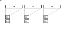
図14及び図15は、本発明の一実施形態に係るストレージ装置4におけるデータ書き込みメカニズムを説明するための図である。具体的には、これらの図は、ある書き込みデータD4〜D6が圧縮された後、RAID1(4D)の下で、疑似ディスクデバイスに格納される様子を説明している。
14 and 15 are diagrams for explaining the data write mechanism in the
あるデータボリュームに対して書き込みデータD4〜D6を格納する場合を考える。説明を簡略化するために、書き込みデータD4〜D6は、ブロックサイズが64KBである単一のデータブロックであるとする。データブロックD4〜D6は、ディスクアダプタ63の制御の下、圧縮され、圧縮データブロックD4−1〜D6−1が得られたとする。また、圧縮データブロックD4−1〜D6−1の複製データ(ミラーリングデータ)を圧縮データブロックD4−1’〜D6−1’で示す。圧縮データブロックのサイズは16KBである。従って、ストレージ装置4は、64KB×3データブロックに対して、16KB×6データブロックを格納することになる(図14)。
Consider a case where write data D4 to D6 are stored in a certain data volume. In order to simplify the description, it is assumed that the write data D4 to D6 are a single data block having a block size of 64 KB. The data blocks D4 to D6 are compressed under the control of the
本実施形態では、図15に示すように、これら圧縮データブロックを、疑似ディスクデバイスごとの実記憶領域に分散して格納するとともに、ミラーリングされた圧縮データブロックを拡張記憶領域に分散して格納する。ただし、本例のように、データサイクルが3であり、疑似ディスクデバイスが4つである場合には、ミラーリングされた圧縮後データブロックの一つを第4の疑似ディスクデバイスの実記憶領域に格納するようにしてもよい。 In this embodiment, as shown in FIG. 15, these compressed data blocks are distributed and stored in the real storage area for each pseudo disk device, and the mirrored compressed data blocks are distributed and stored in the extended storage area. . However, when the data cycle is 3 and there are 4 pseudo disk devices as in this example, one of the mirrored compressed data blocks is stored in the real storage area of the fourth pseudo disk device. You may make it do.
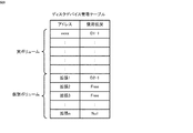
図16は、本発明の一実施形態に係るストレージ装置4における共有メモリ64に格納されたディスクデバイス管理テーブルの一例を示す図である。同図に示すように、本実施形態のディスクデバイス管理テーブルは、スロットIDごとに、第1のアドレス及び第2のアドレスを対応付けている。第2のアドレスは、ミラーリングされた圧縮後データブロックを格納するデータボリュームのアドレスである。
FIG. 16 is a diagram showing an example of a disk device management table stored in the shared
図17は、本発明の一実施形態に係るストレージ装置4におけるデータ書き込み処理を説明するためのフローチャートである。具体的には、同図は、データ書き込み処理時におけるディスクアダプタ63の動作を説明している。なお、本例では、RAIDグループは、4Dであるとする。
FIG. 17 is a flowchart for explaining data write processing in the
すなわち、同図に示すように、ディスクアダプタ63は、共有メモリ64を参照し、未処理の書き込みコマンドを見つけると、キャッシュメモリ62上のそれに対応する書き込みデータを特定する。ディスクアダプタ63は、RAID1に従って、当該書き込みデータを構成するデータブロックに対して圧縮処理を行って、圧縮データブロックを生成すし(STEP1701)、さらに、当該圧縮データブロックを二重化する(STEP1702)。圧縮データブロック及びその二重化された圧縮データブロックは、キャッシュメモリ62における圧縮データ用ブロックに格納される。本例では、3つの圧縮データブロックを1データサイクルとして、二重化された圧縮後データブロックがそれに続いて格納される。
That is, as shown in the figure, when the
ディスクアダプタ63は、次に、圧縮データブロックを系列の異なる疑似ディスクデバイスに分散させて格納するために以下の処理を行う。すなわち、ディスクアダプタ63は、まず、1データサイクル分の圧縮ブロックデータを異なる疑似ディスクデバイス(0)〜疑似ディスクデバイス(2)に分散させて格納する(STEP1703)。次に、ディスクアダプタ63は、データサイクル変数Iに0をセットする(STEP1704)。
Next, the
ディスクアダプタ63は、データサイクル変数Iが0であるか否かを判断する(STEP1705)。つまり、ディスクアダプタ63は、疑似ディスクデバイス(0)に格納された圧縮データブロック(例えばD4−1)に対応する二重化された圧縮データブロック(例えばD4−1’)を選択する。
The
ディスクアダプタ63は、データサイクル変数Iが0であると判断する場合(STEP1705のYes)、当該二重化された圧縮データブロックを疑似ディスクデバイス(3)の実記憶領域に格納し(STEP1706)、データブロック管理テーブルに、当該二重化された圧縮データブロックのエントリを登録する(STEP1707)。
If the
これに対して、データサイクル変数Iが0以外である場合、ディスクアダプタ63は、当該二重化された圧縮後データブロックを、疑似ディスクデバイス(I−1)の拡張記憶領域に格納し(STEP1708)、データブロック管理テーブルに、当該二重化された圧縮データブロックのエントリを登録する(STEP1709)。つまり、疑似ディスクデバイス(0)以外の疑似ディスクデバイスに格納された圧縮データブロックに対応する二重化された圧縮データブロックは、1つ分だけローテイトシフトされた疑似ディスクデバイスに格納されることになる。
On the other hand, if the data cycle variable I is other than 0, the
そして、ディスクアダプタ63は、データサイクル変数Iの値を1つインクリメントして(STEP1710)、データサイクル変数Iが1データサイクルに達したか否かを判断する(STEP1711)。データサイクル変数Iが1データサイクルに達していない場合には(STEP1711のNo)、ディスクアダプタ63は、STEP1705の処理に戻る。一方、データサイクル変数Iが1データサイクルに達した場合には(STEP1711のYes)、当該書き込み処理を終了する。
Then, the
以上のように本実施形態によれば、RAID1の構成の下、書き込みデータの圧縮データをミラーリングして格納する際に、複製された圧縮データを仮想ボリュームに格納しているので、効率的なデータ格納を実現することができるようになる。
[第3の実施形態]
As described above, according to the present embodiment, when the compressed data of the write data is mirrored and stored in the
[Third Embodiment]
第3の実施形態は、上記第1の実施形態で示された技術的特徴と上記第2の実施形態で示された技術的特徴との組み合わせである。具体的には、本実施形態では、ストレージ装置4は、データ書き込み処理時に、パリティグループごとにパリティデータブロックを生成し、各データブロックに対して圧縮処理を行う。ストレージ装置4は、圧縮処理の結果に基づいて、パリティを用いたデータ格納方式とミラーリングによるデータ格納方式のどちらが効率的なデータ格納であるかを判断し、効率的であるとされたデータ格納方式に従って、圧縮データブロックをデータボリュームに格納する。この場合、上述したように、圧縮データブロックは、適宜、仮想ボリュームに格納されることになる。
The third embodiment is a combination of the technical features shown in the first embodiment and the technical features shown in the second embodiment. Specifically, in the present embodiment, the
図18及び図19は、本発明の一実施形態に係るストレージ装置4におけるデータ書き込みメカニズムを説明するための図である。具体的には、これらの図は、ある書き込みデータが圧縮された後、RAID5(3D+1P)またはRAID1(4D)の下で、疑似ディスクデバイスに格納される様子を示している。
18 and 19 are diagrams for explaining the data write mechanism in the
今、あるデータボリュームに対するデータD1の書き込み要求があり、続いて、データD5の書き込み要求があったとする。説明を簡略化するために、書き込みデータは、ブロックサイズが64KBである単一のデータブロックであるとする。RAID5制御の下、書き込みデータ(データブロック)をデータボリュームに格納するためには、それぞれ同一のパリティグループ内のデータブロックとともにパリティを算出して、これらを格納する必要がある。つまり、データブロックD1については、データブロックD2及びD3とともにパリティデータブロックP1が算出され、また、データブロックD5については、データブロックD4及びD6とともにパリティデータブロックP2が算出される。これらは、キャッシュメモリ62上の64KBブロックに格納された圧縮前のデータブロックである。
Assume that there is a write request for data D1 to a certain data volume, and then there is a write request for data D5. To simplify the description, it is assumed that the write data is a single data block having a block size of 64 KB. In order to store the write data (data block) in the data volume under RAID5 control, it is necessary to calculate the parity together with the data block in the same parity group and store them. That is, for the data block D1, the parity data block P1 is calculated together with the data blocks D2 and D3, and for the data block D5, the parity data block P2 is calculated together with the data blocks D4 and D6. These are data blocks before compression stored in 64 KB blocks on the
データブロックD1〜D3及びP1は、ディスクアダプタ63により圧縮され、図18(A)に示すようなデータブロックが得られたとする。これらは、キャッシュメモリ62上の16KBブロックに格納された圧縮データブロックである。上述したように、圧縮データブロックD1−2、D2−2、及びP1−2〜P1−4は、データボリュームの実ボリュームにおける実記憶領域に格納しきれないデータブロックである。
It is assumed that the data blocks D1 to D3 and P1 are compressed by the
一方、データブロックD4〜D6及びP2は、ディスクアダプタ63により圧縮され、図18(B)に示すような圧縮データブロックが得られたとする。つまり、データブロックD4〜D6は、データボリュームの汁ボリュームにおける実記憶領域の1つに格納できるまでに圧縮された圧縮データブロックD4−1〜D6−1に変換されている。また、データブロックP2は、圧縮効率が低く(圧縮率が高く)、圧縮データブロックP2−1〜P2−4に変換されている。なお、本明細書では、圧縮率は、圧縮後のデータサイズを圧縮前のデータサイズで割った値をいうものとする。従って、圧縮率が低いということは、圧縮後のデータサイズが小さいことを意味し、圧縮効率が高いことになる。
On the other hand, it is assumed that the data blocks D4 to D6 and P2 are compressed by the
従って、データブロックD4〜D6及びP2からは、7つの圧縮データブロックが生成される。これに対して、データブロックD4−1〜D6−1が二重化されてデータボリュームに格納される場合、6個の圧縮データブロックが格納されれば足りる。このため、本実施形態のストレージ装置4は、書き込みデータを圧縮後、パリティを含めた圧縮データブロックの数をチェックし、より少ない数の圧縮データブロックを格納すれば足りる方式を選択する。
Accordingly, seven compressed data blocks are generated from the data blocks D4 to D6 and P2. On the other hand, when the data blocks D4-1 to D6-1 are duplicated and stored in the data volume, it is sufficient to store six compressed data blocks. For this reason, the
従って、図19に示すように、圧縮データブロックD1−1、D2−1、D3−1、及びP−1は、RAID5制御の下、データボリュームを構成するRAIDグループにおける疑似ディスクデバイス(0)〜疑似ディスクデバイス(3)の実ボリュームにそれぞれ格納される。また、圧縮データブロックD1−2、D2−2、及びP−2〜P−4は、当該RAIDグループにおける対応する疑似ディスクデバイス(0)〜疑似ディスクデバイス(4)の仮想ボリュームにそれぞれ格納される。 Accordingly, as shown in FIG. 19, the compressed data blocks D1-1, D2-1, D3-1, and P-1 are stored in the pseudo disk devices (0) to (D0) in the RAID group that constitutes the data volume under RAID5 control. Each is stored in a real volume of the pseudo disk device (3). The compressed data blocks D1-2, D2-2, and P-2 to P-4 are respectively stored in the virtual volumes of the corresponding pseudo disk device (0) to pseudo disk device (4) in the RAID group. .
また、圧縮後データブロックD4−1〜D6−1は、RAID1制御の下、ミラーリングされ、拡張記憶領域を利用しながら、疑似ディスクデバイス(0)〜疑似ディスクデバイス(3)に格納される。 The compressed data blocks D4-1 to D6-1 are mirrored under RAID1 control and stored in the pseudo disk device (0) to the pseudo disk device (3) using the extended storage area.
図20は、本発明の一実施形態に係るストレージ装置4における共有メモリ64に格納されたディスクデバイス管理テーブルの一例を示す図である。具体的には、同図は、上述の例に従って、パリティを用いたデータ格納方式により書き込みデータが格納されたときのディスクデバイス管理テーブルを示している。ミラーリングによるデータ格納方式により書き込みデータが格納されたときのディスクデバイス管理テーブルは、図16に示したものと同じである。
FIG. 20 is a diagram showing an example of a disk device management table stored in the shared
図21〜図23は、本発明の一実施形態に係るストレージ装置4におけるデータ書き込み処理を説明するためのフローチャートである。具体的には、同図は、データ書き込み処理時におけるディスクアダプタ63の動作を説明している。
21 to 23 are flowcharts for explaining data write processing in the
すなわち、ディスクアダプタ63は、共有メモリ64を参照し、未処理の書き込みコマンドを見つけると、キャッシュメモリ62上のそれに対応する書き込みデータを特定する。ディスクアダプタ63は、当該書き込みデータに基づいて、RAID構成に従ったパリティデータを生成する(STEP2101)。つまり、本例では、ディスクアダプタ63は、RAID5(3D+1P)の構成に従い、3つのデータブロックごとに1つのパリティデータブロックからなるパリティグループを形成する。このフェースでは、各データブロックは、64KBのブロックサイズである。
That is, when the
続いて、ディスクアダプタ63は、形成したパリティグループ内の各データブロックに対して圧縮処理を行って、圧縮データ列をそれぞれ生成する(STEP2102)。ディスクアダプタ63は、各圧縮データ列を構成する圧縮データブロックのそれぞれをキャッシュメモリ62における圧縮データ用ブロックに書き込み、キャッシュ管理テーブルを更新する。圧縮データ用ブロックは、例えば、16KBのブロックサイズである。
Subsequently, the
ディスクアダプタ63は、次に、パリティグループ内の圧縮データブロック(圧縮パリティデータブロックを含まない。)数が圧縮パリティデータブロック数よりも少ないか否かを判断する(STEP2103)。つまり、ディスクアダプタ63は、パリティを用いたデータ格納方式とミラーリングによるデータ格納方式のどちらが書き込みデータを効率的に格納できるか否かを判断する。
Next, the
ディスクアダプタ63は、パリティグループ内の圧縮データブロック数の方が圧縮パリティデータブロック数よりも少ないと判断する場合には、図22に示す処理を行う。図22に示す処理は、パリティを用いたデータ格納処理であり、図12に示したSTEP1203以降の処理と同じであるため、説明を省略する。
If the
これに対して、ディスクアダプタ63は、パリティグループ内の圧縮後データブロック数の方が圧縮後パリティデータブロック数よりも多いと判断する場合には、図23に示す処理を行う。図23に示す処理は、ミラーリングによるデータ格納処理であり、図17に示したSTEP1702以降の処理と同じであるため、説明を省略する。
On the other hand, when the
以上のように、本実施形態によれば、書き込みデータを圧縮して格納するに際して、パリティを含む圧縮データのサイズとパリティを用いずに二重化した圧縮データのサイズとに基づいて最適なRAID構成を選択するので、圧縮データの効率的な格納ができるようになる。
[第4の実施形態]
As described above, according to the present embodiment, when writing data is compressed and stored, an optimum RAID configuration is based on the size of compressed data including parity and the size of compressed data that is duplicated without using parity. Since the selection is made, the compressed data can be efficiently stored.
[Fourth Embodiment]
第4の実施形態は、第3の実施形態の変形であり、データの書き込み要求に対する前回のデータ格納方式を記憶しておき、当該データに対する別の書き込み要求があった場合に、当該記憶されたデータ格納方式を利用することを特徴としている。 The fourth embodiment is a modification of the third embodiment, stores the previous data storage method for a data write request, and stores the stored data when there is another write request for the data. It is characterized by using a data storage method.
図24(A)及び(B)は、本発明の一実施形態に係るストレージ装置4における共有メモリ64に格納されたディスクデバイス管理テーブルの一例を示す図である。同図に示すように、本実施形態のディスクデバイス管理テーブルは、上述したディスクデバイス管理テーブルのほぼ同じであるが、前回のデータ格納方式を記憶する学習情報を保持する点が異なっている。すなわち、同図(A)は、RAID5を学習情報として保持した状態を示し、同図(B)は、学習情報がない状態を示している。
24A and 24B are diagrams showing an example of a disk device management table stored in the shared
図25は、本発明の一実施形態に係るストレージ装置4におけるデータ書き込み処理を説明するためのフローチャートである。
FIG. 25 is a flowchart for explaining data write processing in the
同図に示すように、ディスクアダプタ63は、共有メモリ64を参照し、未処理の書き込みコマンドを見つけると、キャッシュメモリ62上のそれに対応する書き込みデータを特定する。ディスクアダプタ63は、当該書き込みデータに対するデータブロック管理テーブルを参照して、現在の学習情報を取得し(STEP2501)、現在の学習情報が“RAID1”であるか否かを判断する(STEP2502)。
As shown in the figure, when the
ディスクアダプタ63は、現在の学習情報が“RAID1”でないと判断する場合(STEP2502のNo)、RAID5の制御の下で、圧縮データの格納処理を行う。
If the
すなわち、ディスクアダプタ63は、すでに述べたように、RAID構成に従ったパリティデータブロックを生成し(STEP2503)、続いて、パリティグループ内の各データブロックを圧縮する(STEP2504)。
That is, as already described, the
ディスクアダプタ63は、次に、パリティグループ内の圧縮データブロック(圧縮パリティデータブロックを含まない。)数が圧縮パリティデータブロック数よりも少ないか否かを判断する(STEP2505)。つまり、ディスクアダプタ63は、パリティを用いたデータ格納方式とミラーリングを用いたデータ格納方式のどちらが書き込みデータを効率的に格納できるか否かを判断する。
Next, the
ディスクアダプタ63は、パリティグループ内の圧縮データブロック数の方が圧縮パリティデータブロック数よりも多いと判断する場合には、ミラーリングによるデータ格納処理を行う(STEP2509)。ミラーリングによるデータ格納処理は、図23に示した処理と同じである。
If the
これに対して、ディスクアダプタ63は、パリティグループ内の圧縮データブロック数の方が圧縮パリティデータブロック数よりも少ないと判断する場合には、パリティを用いたデータ格納処理を行う(STEP2506)。パリティを用いたデータ格納処理は、図22に示した処理と同じである。
In contrast, if the
そして、ディスクアダプタ63は、次回のデータ書き込み処理のため、データブロック管理テーブルの学習情報を“RAID5”に設定する(STEP2507)。
Then, the
STEP2502において、現在の学習情報が“RAID1”であると判断する場合(STEP2502のYes)、RAID1の制御の下で、圧縮データの格納処理を行う。 If it is determined in STEP 2502 that the current learning information is “RAID1” (YES in STEP2502), a compressed data storage process is performed under the control of RAID1.
すなわち、ディスクアダプタ63は、まず、データブロックを圧縮し(STEP2508)、続いて、ミラーリングによるデータ格納処理を行う(STEP2509)。
That is, the
ミラーリングによるデータ格納処理を終えた後、ディスクアダプタ63は、学習情報を更新するか否かを判断すべく、RAID構成に従ったパリティデータブロックを生成し(STEP2510)、続いて、パリティグループ内の各データブロックを圧縮する(STEP2511)。ディスクアダプタ53は、パリティグループ内の圧縮データブロック(圧縮後パリティデータブロックを含まない。)数が圧縮パリティデータブロック数よりも少ないか否かを判断する(STEP2512)。
After finishing the data storage processing by mirroring, the
ディスクアダプタ63は、パリティグループ内の圧縮データブロック数の方が圧縮パリティデータブロック数よりも少ないと判断する場合には(STEP2512のYes)、データブロック管理テーブルの学習情報を“RAID5”に設定する(STEP2507)。
When the
これに対して、ディスクアダプタ63は、パリティグループ内の圧縮後データブロック数の方が圧縮後パリティデータブロック数よりも多いと判断する場合には(STEP2512のNo)、データブロック管理テーブルの学習情報を“RAID1”に設定する(STEP2513)。
On the other hand, when the
以上により、本実施形態によれば、前回のデータ格納方式を記憶しているため、さらに効率的なRAID構成の選択を行うことができるようになる。 As described above, according to the present embodiment, since the previous data storage method is stored, a more efficient RAID configuration can be selected.
上記実施形態は、本発明を説明するための例示であり、本発明は上記実施形態に限定されるものでない。本発明は、その要旨を逸脱しない範囲でさまざまに形態で実施することができる。 The said embodiment is an illustration for demonstrating this invention, and this invention is not limited to the said embodiment. The present invention can be implemented in various forms without departing from the gist thereof.
例えば、上記実施形態では、ディスクアダプタの動作をフローチャートの中でシーケンシャルに構成したが、動作果に矛盾が生じない限り、処理の順序を入れ替え、又は、並列に処理するように構成してもよい。 For example, in the above-described embodiment, the operation of the disk adapter is configured sequentially in the flowchart. However, as long as there is no contradiction in the operation result, the processing order may be changed or the processing may be performed in parallel. .
また、上記実施形態では、RAID5を採用したが、パリティを用いる他のRAID構成として知られるRAID3、4、又は6であってもよい。 Moreover, in the said embodiment, although RAID5 was employ | adopted, RAID3, 4, or 6 known as another RAID structure using a parity may be sufficient.
本発明は、RAID構成を採用するストレージ装置に広く適用することができる。 The present invention can be widely applied to storage apparatuses that employ a RAID configuration.
1…コンピュータシステム
2…ネットワーク
3…ホスト装置
4…ストレージ装置
5…ディスクデバイス
6…ディスクコントローラ
61…チャネルアダプタ
62…キャッシュメモリ
63…ディスクアダプタ
64…共有メモリ
65…内部スイッチ
DESCRIPTION OF
Claims (10)
前記ディスクコントローラは、
ホスト装置に接続するためのチャネルアダプタと、
前記ディスクデバイスに接続されたディスクアダプタと、
前記チャネルアダプタと前記ディスクアダプタとの間でやり取りされるデータを一時的に格納するキャッシュメモリと、を備え、
前記ディスクアダプタは、
前記記憶媒体の固有記憶容量よりも大きな記憶容量が定義され、前記記憶媒体の記憶領域に対応付けられた実ボリューム及び前記実ボリューム以外の記憶領域が割り当てられた仮想ボリュームを含むデータボリュームと、前記仮想ボリュームに割り当てられた記憶領域に対するデータを格納するための記憶領域が割り当てられたプールボリュームとを形成するように、前記ディスクデバイスを制御し、
前記ディスクアダプタは、
所定のRAID構成による制御の下、前記ホスト装置から送られた書き込み要求に従う書き込みデータに基づいて、当該書き込みデータが属するパリティグループ内のパリティデータを生成し、
前記パリティグループ内の前記書き込みデータ及び前記生成されたパリティデータのそれぞれを圧縮して、圧縮データ及び圧縮パリティデータを生成し、
前記パリティグループ内の前記圧縮データ及び前記圧縮パリティデータのそれぞれが所定のサイズを超えるか否かを判断し、
前記圧縮データ及び前記圧縮パリティデータのうち前記所定のサイズを超えない分のデータを前記実ボリュームの記憶領域に格納し、前記圧縮データ及び前記圧縮パリティデータのうち前記所定のサイズを超える分のデータを前記仮想ボリュームに対応する前記プールボリュームの記憶領域に格納することを特徴とするストレージ装置。 A storage device comprising: a disk device having a storage medium for storing data; and a disk controller for controlling the disk device,
The disk controller is
A channel adapter for connecting to the host device;
A disk adapter connected to the disk device;
A cache memory for temporarily storing data exchanged between the channel adapter and the disk adapter,
The disk adapter is
A data volume including a virtual volume to which a storage capacity larger than a specific storage capacity of the storage medium is defined, a real volume associated with the storage area of the storage medium, and a storage area other than the real volume, and Controlling the disk device to form a pool volume to which a storage area for storing data for the storage area assigned to the virtual volume is assigned;
The disk adapter is
Based on write data in accordance with a write request sent from the host device under control by a predetermined RAID configuration, parity data in a parity group to which the write data belongs is generated,
Compressing each of the write data and the generated parity data in the parity group to generate compressed data and compressed parity data;
Determining whether each of the compressed data and the compressed parity data in the parity group exceeds a predetermined size;
Data that does not exceed the predetermined size among the compressed data and the compressed parity data is stored in the storage area of the real volume, and data that exceeds the predetermined size among the compressed data and the compressed parity data Is stored in a storage area of the pool volume corresponding to the virtual volume.
前記ディスクアダプタは、
前記書き込みデータを構成するデータブロック及び前記パリティグループ内の他のデータブロックに基づいて前記パリティデータのデータブロックを生成し、
前記パリティグループ内の前記データブロックのそれぞれに対して圧縮することにより得られる圧縮データ列が所定数を超える圧縮データブロックにより構成されているか否かに従って、前記所定のサイズを超えているか否かを判断し、
前記所定数を超えていない前記圧縮データブロックを前記実ボリュームの記憶領域に格納し、前記所定数を超えている前記圧縮データブロックを前記仮想ボリュームに対応する前記プールボリュームの記憶領域に格納することを特徴とするストレージ装置。 The storage device according to claim 1,
The disk adapter is
Generating a data block of the parity data based on a data block constituting the write data and another data block in the parity group;
Whether or not the compressed data string obtained by compressing each of the data blocks in the parity group exceeds the predetermined size according to whether or not the compressed data string is composed of compressed data blocks exceeding a predetermined number. Judgment
Storing the compressed data blocks not exceeding the predetermined number in the storage area of the real volume, and storing the compressed data blocks exceeding the predetermined number in the storage area of the pool volume corresponding to the virtual volume. A storage device.
前記ディスクアダプタは、
前記パリティグループ内の前記圧縮データブロックのそれぞれを、前記データボリュームを構成する物理的に異なる系列のディスクデバイスに分散させて格納することを特徴とするストレージ装置。 The storage device according to claim 2,
The disk adapter is
A storage apparatus, wherein each of the compressed data blocks in the parity group is distributed and stored in disk devices of physically different series constituting the data volume.
前記ディスクアダプタは、
前記圧縮データセットを構成する前記圧縮データブロックは、前記データボリュームを構成する同一系列のディスクデバイスに形成される実ボリューム及び仮想ボリュームに格納することを特徴とするストレージ装置。 The storage device according to claim 3,
The disk adapter is
The storage apparatus, wherein the compressed data block constituting the compressed data set is stored in a real volume and a virtual volume formed in the same series of disk devices constituting the data volume.
前記パリティグループ内の前記データブロックのそれぞれを格納する、前記キャッシュメモリ上に形成された記憶領域のサイズは、前記実ボリュームの単位記憶領域のサイズよりも大きいことを特徴とするストレージ装置。 The storage device according to claim 2,
The storage apparatus according to claim 1, wherein a size of a storage area formed on the cache memory for storing each of the data blocks in the parity group is larger than a size of a unit storage area of the real volume.
前記ディスクアダプタは、
前記パリティデータの圧縮データブロックを除く圧縮データブロックの数が、前記パリティーデータの圧縮データブロックの数よりも少ないか否かを判断し、
前記前記パリティデータの圧縮データブロックを除く圧縮データブロックの数が、前記パリティーデータの圧縮データブロックの数よりも少ないと判断する場合に、前記所定数を超えていない前記圧縮データブロックを前記実ボリュームの記憶領域に格納し、前記所定数を超えている前記圧縮データブロックを前記仮想ボリュームに対応する前記プールボリュームの記憶領域に格納することを特徴とするストレージ装置。 The storage device according to claim 2,
The disk adapter is
Determining whether the number of compressed data blocks excluding the compressed data block of the parity data is less than the number of compressed data blocks of the parity data;
When it is determined that the number of compressed data blocks excluding the compressed data blocks of the parity data is smaller than the number of compressed data blocks of the parity data, the compressed data blocks that do not exceed the predetermined number are And storing the compressed data blocks exceeding the predetermined number in the storage area of the pool volume corresponding to the virtual volume.
前記ディスクアダプタは、
前記パリティデータの圧縮データブロックを除く圧縮データブロックの数が、前記パリティーデータの圧縮データブロックの数よりも多いと判断する場合に、前記パリティデータの圧縮データブロックを除く圧縮データブロックのそれぞれを二重化し、
前記二重化した圧縮データブロックのそれぞれを、前記データボリュームを構成する物理的に異なる系列のディスクデバイスに格納することを特徴とするストレージ装置。 The storage apparatus according to claim 6, wherein
The disk adapter is
When it is determined that the number of compressed data blocks excluding the compressed data block of the parity data is larger than the number of compressed data blocks of the parity data, each of the compressed data blocks excluding the compressed data block of the parity data is duplicated And
Each of the duplex compressed data blocks is stored in a physically different series of disk devices constituting the data volume.
前記ディスクアダプタは、
前記パリティグループ内の前記二重化された圧縮データブロックのそれぞれのうち一方の圧縮データブロックを前記データボリュームの実ボリュームに格納し、他方の圧縮データブロックを前記データボリュームの仮想ボリュームに格納することを特徴とするストレージ装置。 The storage apparatus according to claim 7, wherein
The disk adapter is
One compressed data block of each of the duplicated compressed data blocks in the parity group is stored in a real volume of the data volume, and the other compressed data block is stored in a virtual volume of the data volume. Storage device.
前記ディスクアダプタは、
前記書き込み要求に従う書き込みデータに対するRAID構成によるデータ格納方式を記憶し、当該記憶されたデータ格納方式に従って、前記書き込みデータを圧縮して、前記データボリュームに格納することを特徴とするストレージ装置。 The storage device according to claim 1,
The disk adapter is
A storage apparatus that stores a data storage method based on a RAID configuration for write data according to the write request, compresses the write data according to the stored data storage method, and stores the compressed data in the data volume.
前記データ格納方法は、
前記ディスクコントローラが、前記記憶媒体の固有記憶容量よりも大きな記憶容量が定義され、前記記憶媒体の記憶領域に対応付けられた実ボリューム及び前記実ボリューム以外の記憶領域が割り当てられた仮想ボリュームを含むデータボリュームと、前記仮想ボリュームに割り当てられた記憶領域に対するデータを格納するための記憶領域が割り当てられたプールボリュームとが形成されるように、前記ディスクデバイスを制御するステップと、
前記ディスクコントローラが、所定のRAID構成に従い、前記ホスト装置から送られた書き込み要求に従う書き込みデータに基づいて、当該書き込みデータが属するパリティグループ内のパリティデータを生成するステップと、
前記ディスクコントローラが、前記パリティグループ内の前記書き込みデータ及び前記生成されたパリティデータのそれぞれを圧縮して、圧縮データ及び圧縮パリティデータを生成するステップと、
前記ディスクコントローラが、前記パリティグループ内の前記圧縮データ及び前記圧縮パリティデータのそれぞれが所定のサイズを超えるか否かを判断するステップと、
前記ディスクコントローラが、前記圧縮データ及び前記圧縮パリティデータのうち前記所定のサイズを超えない分のデータを前記実ボリュームの記憶領域に格納するとともに、前記圧縮データ及び前記圧縮パリティデータのうち前記所定のサイズを超える分のデータを前記仮想ボリュームに対応する前記プールボリュームの記憶領域に格納するステップと、を含むことを特徴とするデータ格納方法。 A data storage method in a storage device comprising: a disk device having a storage medium for storing data; and a disk controller for controlling the disk device,
The data storage method is:
The disk controller includes a virtual volume in which a storage capacity larger than a specific storage capacity of the storage medium is defined, and a real volume associated with a storage area of the storage medium and a storage area other than the real volume are allocated. Controlling the disk device to form a data volume and a pool volume to which a storage area for storing data for the storage area assigned to the virtual volume is formed; and
The disk controller generates parity data in a parity group to which the write data belongs based on write data according to a write request sent from the host device according to a predetermined RAID configuration;
The disk controller compressing each of the write data and the generated parity data in the parity group to generate compressed data and compressed parity data;
The disk controller determining whether each of the compressed data and the compressed parity data in the parity group exceeds a predetermined size; and
The disk controller stores, in the storage area of the real volume, data that does not exceed the predetermined size of the compressed data and the compressed parity data, and the predetermined data of the compressed data and the compressed parity data. Storing data exceeding the size in a storage area of the pool volume corresponding to the virtual volume.
Priority Applications (5)
| Application Number | Priority Date | Filing Date | Title |
|---|---|---|---|
| JP2007272900A JP5112003B2 (en) | 2007-10-19 | 2007-10-19 | Storage device and data storage method using the same |
| US12/007,940 US8037244B2 (en) | 2007-10-19 | 2008-01-17 | Storage apparatus and data storage method using the same |
| EP08251492A EP2051167A3 (en) | 2007-10-19 | 2008-04-22 | Storage apparatus and data storage method using the same |
| CN2008101089125A CN101414245B (en) | 2007-10-19 | 2008-06-06 | Storage apparatus and data storage method using the same |
| US13/191,079 US8171217B2 (en) | 2007-10-19 | 2011-07-26 | Storage apparatus and data storage method using the same |
Applications Claiming Priority (1)
| Application Number | Priority Date | Filing Date | Title |
|---|---|---|---|
| JP2007272900A JP5112003B2 (en) | 2007-10-19 | 2007-10-19 | Storage device and data storage method using the same |
Publications (3)
| Publication Number | Publication Date |
|---|---|
| JP2009104236A true JP2009104236A (en) | 2009-05-14 |
| JP2009104236A5 JP2009104236A5 (en) | 2010-04-22 |
| JP5112003B2 JP5112003B2 (en) | 2013-01-09 |
Family
ID=40364298
Family Applications (1)
| Application Number | Title | Priority Date | Filing Date |
|---|---|---|---|
| JP2007272900A Expired - Fee Related JP5112003B2 (en) | 2007-10-19 | 2007-10-19 | Storage device and data storage method using the same |
Country Status (4)
| Country | Link |
|---|---|
| US (2) | US8037244B2 (en) |
| EP (1) | EP2051167A3 (en) |
| JP (1) | JP5112003B2 (en) |
| CN (1) | CN101414245B (en) |
Cited By (5)
| Publication number | Priority date | Publication date | Assignee | Title |
|---|---|---|---|---|
| WO2015075837A1 (en) * | 2013-11-25 | 2015-05-28 | 株式会社日立製作所 | Storage device and control method therefor |
| WO2015087424A1 (en) * | 2013-12-12 | 2015-06-18 | 株式会社日立製作所 | Storage device and method for controlling storage device |
| WO2016151831A1 (en) * | 2015-03-26 | 2016-09-29 | 株式会社日立製作所 | Storage system |
| JP2018014129A (en) * | 2017-09-14 | 2018-01-25 | 株式会社日立製作所 | Storage device and method of controlling storage device |
| US11112971B2 (en) | 2017-10-20 | 2021-09-07 | Hitachi, Ltd. | Storage device, data management method, and data management program |
Families Citing this family (28)
| Publication number | Priority date | Publication date | Assignee | Title |
|---|---|---|---|---|
| JP2009098996A (en) * | 2007-10-18 | 2009-05-07 | Hitachi Ltd | Storage system |
| US8650328B1 (en) * | 2008-12-15 | 2014-02-11 | American Megatrends, Inc. | Bi-directional communication between redundant storage controllers |
| CN101556557B (en) * | 2009-05-14 | 2011-03-23 | 浙江大学 | Object file organization method based on object storage device |
| JP5423407B2 (en) * | 2010-01-08 | 2014-02-19 | 富士通株式会社 | Storage management device, storage management method, and storage management program |
| US8112663B2 (en) * | 2010-03-26 | 2012-02-07 | Lsi Corporation | Method to establish redundancy and fault tolerance better than RAID level 6 without using parity |
| US8181062B2 (en) * | 2010-03-26 | 2012-05-15 | Lsi Corporation | Method to establish high level of redundancy, fault tolerance and performance in a raid system without using parity and mirroring |
| CN102012865A (en) * | 2010-10-27 | 2011-04-13 | 威海威高电子工程有限公司 | Quantized data storage method |
| CN102073830B (en) * | 2011-01-12 | 2014-05-14 | 深圳昂楷科技有限公司 | Method for dynamically extending additional information of transparent encrypted file |
| US8909891B2 (en) * | 2011-07-21 | 2014-12-09 | International Business Machines Corporation | Virtual logical volume for overflow storage of special data sets |
| EP2884394A4 (en) * | 2012-11-19 | 2016-04-27 | Hitachi Ltd | Administration system and administration method |
| CN104937561B (en) * | 2013-05-17 | 2018-01-02 | 株式会社日立制作所 | Storage device |
| US9619389B1 (en) | 2013-07-11 | 2017-04-11 | Unigen Corporation | System for a backward and forward application environment compatible distributed shared coherent storage |
| KR102088403B1 (en) | 2013-08-08 | 2020-03-13 | 삼성전자 주식회사 | Storage device, computer system comprising the same, and operating method thereof |
| CN105022586B (en) * | 2014-04-17 | 2018-06-05 | 中国移动通信集团公司 | A kind of data processing method, device and system |
| US9830220B1 (en) * | 2014-09-29 | 2017-11-28 | EMC IP Holding Company LLC | Enhanced error recovery for data storage drives |
| WO2016073018A1 (en) * | 2014-11-04 | 2016-05-12 | Hewlett Packard Enterprise Development Lp | Storing excess data in a raid 60 array |
| CN104778018B (en) * | 2015-04-23 | 2018-06-05 | 南京道熵信息技术有限公司 | Wide band disk array and storage method based on asymmetric hybrid magnetic disk mirroring |
| WO2017000097A1 (en) * | 2015-06-27 | 2017-01-05 | 华为技术有限公司 | Data forwarding method, device, and system |
| CN105739930B (en) * | 2016-02-02 | 2019-01-08 | 华为技术有限公司 | A kind of storage architecture and its initial method and date storage method and managing device |
| US10437667B2 (en) | 2016-03-29 | 2019-10-08 | International Business Machines Corporation | Raid system performance enhancement using compressed data |
| US10037245B2 (en) | 2016-03-29 | 2018-07-31 | International Business Machines Corporation | Raid system performance enhancement using compressed data and byte addressable storage devices |
| CN107305476B (en) * | 2016-04-25 | 2020-03-31 | 群联电子股份有限公司 | Data correction method, memory control circuit unit and memory storage device |
| US10545675B2 (en) * | 2016-08-22 | 2020-01-28 | SK Hynix Inc. | Memory system including multi-interfaces |
| US20190302724A1 (en) * | 2016-10-21 | 2019-10-03 | Kabushiki Kaisha Toshiba | Controller |
| CN107577551A (en) * | 2017-09-06 | 2018-01-12 | 郑州云海信息技术有限公司 | A kind of solid state disk write fail processing method and system |
| US10852966B1 (en) * | 2017-10-18 | 2020-12-01 | EMC IP Holding Company, LLC | System and method for creating mapped RAID group during expansion of extent pool |
| JP2020080130A (en) * | 2018-11-14 | 2020-05-28 | 株式会社日立製作所 | Volume management device, volume management method, and volume management program |
| US11372984B2 (en) * | 2019-08-14 | 2022-06-28 | International Business Machines Corporation | Key-compressible encryption |
Citations (4)
| Publication number | Priority date | Publication date | Assignee | Title |
|---|---|---|---|---|
| JPH05189157A (en) * | 1992-01-13 | 1993-07-30 | Toshiba Corp | Disk type storage device |
| JPH07261938A (en) * | 1994-03-24 | 1995-10-13 | Hitachi Ltd | Storage control method and disk system with compressing function using the storage control method |
| JP2004013373A (en) * | 2002-06-05 | 2004-01-15 | Hitachi Ltd | External storage device system and storage controller |
| JP2007199891A (en) * | 2006-01-25 | 2007-08-09 | Hitachi Ltd | Storage system and storage control apparatus |
Family Cites Families (8)
| Publication number | Priority date | Publication date | Assignee | Title |
|---|---|---|---|---|
| US5247638A (en) | 1990-06-18 | 1993-09-21 | Storage Technology Corporation | Apparatus for compressing data in a dynamically mapped virtual data storage subsystem |
| JP2550239B2 (en) * | 1991-09-12 | 1996-11-06 | 株式会社日立製作所 | External storage system |
| EP1376329A2 (en) * | 1994-06-22 | 2004-01-02 | Hewlett-Packard Company, A Delaware Corporation | Method of utilizing storage disks of differing capacity in a single storage volume in a hierarchic disk array |
| US6442659B1 (en) * | 1998-02-17 | 2002-08-27 | Emc Corporation | Raid-type storage system and technique |
| US7051152B1 (en) * | 2002-08-07 | 2006-05-23 | Nvidia Corporation | Method and system of improving disk access time by compression |
| US7350101B1 (en) * | 2002-12-23 | 2008-03-25 | Storage Technology Corporation | Simultaneous writing and reconstruction of a redundant array of independent limited performance storage devices |
| CN1523504A (en) * | 2003-02-18 | 2004-08-25 | 盖内蒂克瓦尔有限公司 | Information checking apparatus and method for guaranteeing security and non-modification property for remote loading data |
| US9007603B2 (en) | 2006-03-31 | 2015-04-14 | Konica Minolta Laboratory U.S.A., Inc. | Print management method and apparatus with destination panel |
-
2007
- 2007-10-19 JP JP2007272900A patent/JP5112003B2/en not_active Expired - Fee Related
-
2008
- 2008-01-17 US US12/007,940 patent/US8037244B2/en not_active Expired - Fee Related
- 2008-04-22 EP EP08251492A patent/EP2051167A3/en not_active Withdrawn
- 2008-06-06 CN CN2008101089125A patent/CN101414245B/en active Active
-
2011
- 2011-07-26 US US13/191,079 patent/US8171217B2/en active Active
Patent Citations (4)
| Publication number | Priority date | Publication date | Assignee | Title |
|---|---|---|---|---|
| JPH05189157A (en) * | 1992-01-13 | 1993-07-30 | Toshiba Corp | Disk type storage device |
| JPH07261938A (en) * | 1994-03-24 | 1995-10-13 | Hitachi Ltd | Storage control method and disk system with compressing function using the storage control method |
| JP2004013373A (en) * | 2002-06-05 | 2004-01-15 | Hitachi Ltd | External storage device system and storage controller |
| JP2007199891A (en) * | 2006-01-25 | 2007-08-09 | Hitachi Ltd | Storage system and storage control apparatus |
Cited By (8)
| Publication number | Priority date | Publication date | Assignee | Title |
|---|---|---|---|---|
| WO2015075837A1 (en) * | 2013-11-25 | 2015-05-28 | 株式会社日立製作所 | Storage device and control method therefor |
| WO2015087424A1 (en) * | 2013-12-12 | 2015-06-18 | 株式会社日立製作所 | Storage device and method for controlling storage device |
| GB2536514A (en) * | 2013-12-12 | 2016-09-21 | Hitachi Ltd | Storage device and method for controlling storage device |
| JPWO2015087424A1 (en) * | 2013-12-12 | 2017-03-16 | 株式会社日立製作所 | Storage device and storage device control method |
| US9916248B2 (en) | 2013-12-12 | 2018-03-13 | Hitachi, Ltd. | Storage device and method for controlling storage device with compressed and uncompressed volumes and storing compressed data in cache |
| WO2016151831A1 (en) * | 2015-03-26 | 2016-09-29 | 株式会社日立製作所 | Storage system |
| JP2018014129A (en) * | 2017-09-14 | 2018-01-25 | 株式会社日立製作所 | Storage device and method of controlling storage device |
| US11112971B2 (en) | 2017-10-20 | 2021-09-07 | Hitachi, Ltd. | Storage device, data management method, and data management program |
Also Published As
| Publication number | Publication date |
|---|---|
| US8171217B2 (en) | 2012-05-01 |
| US20090106492A1 (en) | 2009-04-23 |
| US8037244B2 (en) | 2011-10-11 |
| EP2051167A3 (en) | 2011-05-04 |
| US20110283064A1 (en) | 2011-11-17 |
| CN101414245A (en) | 2009-04-22 |
| CN101414245B (en) | 2011-10-26 |
| JP5112003B2 (en) | 2013-01-09 |
| EP2051167A2 (en) | 2009-04-22 |
Similar Documents
| Publication | Publication Date | Title |
|---|---|---|
| JP5112003B2 (en) | Storage device and data storage method using the same | |
| CN111158587B (en) | Distributed storage system based on storage pool virtualization management and data read-write method | |
| US9152332B2 (en) | Storage system and method for reducing energy consumption | |
| US10073621B1 (en) | Managing storage device mappings in storage systems | |
| CN107817952B (en) | Storage system | |
| US8555029B2 (en) | Virtualized storage system and method of operating thereof | |
| US9519554B2 (en) | Storage system with rebuild operations | |
| US8650360B2 (en) | Storage system | |
| US8225039B2 (en) | Storage controller and virtual volume control method | |
| JP2009043030A (en) | Storage system | |
| WO2016142998A1 (en) | Computer system | |
| WO2017175285A1 (en) | Computing machine system, control method for physical storage device, and recording medium | |
| US20080195832A1 (en) | Storage controller and storage system | |
| CN113342258B (en) | Method and apparatus for data access management of an all-flash memory array server | |
| CN116483263A (en) | Storage device of storage system and storage system | |
| JP5597266B2 (en) | Storage system | |
| US20180307427A1 (en) | Storage control apparatus and storage control method | |
| US11561695B1 (en) | Using drive compression in uncompressed tier |
Legal Events
| Date | Code | Title | Description |
|---|---|---|---|
| RD04 | Notification of resignation of power of attorney |
Free format text: JAPANESE INTERMEDIATE CODE: A7424 Effective date: 20090223 |
|
| A521 | Written amendment |
Free format text: JAPANESE INTERMEDIATE CODE: A523 Effective date: 20100303 |
|
| A621 | Written request for application examination |
Free format text: JAPANESE INTERMEDIATE CODE: A621 Effective date: 20100303 |
|
| A977 | Report on retrieval |
Free format text: JAPANESE INTERMEDIATE CODE: A971007 Effective date: 20120118 |
|
| A131 | Notification of reasons for refusal |
Free format text: JAPANESE INTERMEDIATE CODE: A131 Effective date: 20120306 |
|
| A521 | Written amendment |
Free format text: JAPANESE INTERMEDIATE CODE: A523 Effective date: 20120507 |
|
| TRDD | Decision of grant or rejection written | ||
| A01 | Written decision to grant a patent or to grant a registration (utility model) |
Free format text: JAPANESE INTERMEDIATE CODE: A01 Effective date: 20120911 |
|
| A01 | Written decision to grant a patent or to grant a registration (utility model) |
Free format text: JAPANESE INTERMEDIATE CODE: A01 |
|
| A61 | First payment of annual fees (during grant procedure) |
Free format text: JAPANESE INTERMEDIATE CODE: A61 Effective date: 20121010 |
|
| FPAY | Renewal fee payment (event date is renewal date of database) |
Free format text: PAYMENT UNTIL: 20151019 Year of fee payment: 3 |
|
| R150 | Certificate of patent or registration of utility model |
Ref document number: 5112003 Country of ref document: JP Free format text: JAPANESE INTERMEDIATE CODE: R150 Free format text: JAPANESE INTERMEDIATE CODE: R150 |
|
| LAPS | Cancellation because of no payment of annual fees |