JP2009098996A - Storage system - Google Patents
Storage system Download PDFInfo
- Publication number
- JP2009098996A JP2009098996A JP2007270902A JP2007270902A JP2009098996A JP 2009098996 A JP2009098996 A JP 2009098996A JP 2007270902 A JP2007270902 A JP 2007270902A JP 2007270902 A JP2007270902 A JP 2007270902A JP 2009098996 A JP2009098996 A JP 2009098996A
- Authority
- JP
- Japan
- Prior art keywords
- data
- redundant code
- storage
- compressed
- redundant
- Prior art date
- Legal status (The legal status is an assumption and is not a legal conclusion. Google has not performed a legal analysis and makes no representation as to the accuracy of the status listed.)
- Pending
Links
Images


Classifications
-
- G—PHYSICS
- G06—COMPUTING; CALCULATING OR COUNTING
- G06F—ELECTRIC DIGITAL DATA PROCESSING
- G06F11/00—Error detection; Error correction; Monitoring
- G06F11/07—Responding to the occurrence of a fault, e.g. fault tolerance
- G06F11/08—Error detection or correction by redundancy in data representation, e.g. by using checking codes
- G06F11/10—Adding special bits or symbols to the coded information, e.g. parity check, casting out 9's or 11's
- G06F11/1076—Parity data used in redundant arrays of independent storages, e.g. in RAID systems
-
- G—PHYSICS
- G06—COMPUTING; CALCULATING OR COUNTING
- G06F—ELECTRIC DIGITAL DATA PROCESSING
- G06F2211/00—Indexing scheme relating to details of data-processing equipment not covered by groups G06F3/00 - G06F13/00
- G06F2211/10—Indexing scheme relating to G06F11/10
- G06F2211/1002—Indexing scheme relating to G06F11/1076
- G06F2211/1014—Compression, i.e. RAID systems with parity using compression techniques
Landscapes
- Engineering & Computer Science (AREA)
- Theoretical Computer Science (AREA)
- Quality & Reliability (AREA)
- Physics & Mathematics (AREA)
- General Engineering & Computer Science (AREA)
- General Physics & Mathematics (AREA)
- Information Retrieval, Db Structures And Fs Structures Therefor (AREA)
- Techniques For Improving Reliability Of Storages (AREA)
Abstract
Description
本発明は、ストレージシステムに関し、特に、データ要素のリストアに関する。 The present invention relates to storage systems, and more particularly, to restoration of data elements.
一般に、RAID(Redundant Arrays of Independent (or Inexpensive) Disks)と呼ばれる技術が採用されているストレージシステムには、複数の記憶装置で構成されたRAIDグループが備えられている。RAIDグループの記憶領域は、複数のサブ記憶領域列で構成されている。各サブ記憶領域列は、RAIDグループを構成する複数の記憶装置に跨っており、複数の記憶装置に対応した複数のサブ記憶領域で構成されている。以下、一つのサブ記憶領域を、「ストライプ」と呼び、複数のストライプで構成された一列を、「ストライプ列」と呼ぶ。連続したストライプ列によって、RAIDグループの記憶領域が構成されている。 In general, a storage system employing a technique called RAID (Redundant Arrays of Independent (or Inexpensive) Disks) includes a RAID group composed of a plurality of storage devices. The storage area of the RAID group is composed of a plurality of sub storage area columns. Each sub storage area column spans a plurality of storage devices constituting the RAID group, and includes a plurality of sub storage areas corresponding to the plurality of storage devices. Hereinafter, one sub storage area is referred to as a “stripe”, and one column composed of a plurality of stripes is referred to as a “stripe column”. A storage area of the RAID group is configured by continuous stripe columns.
RAIDには、いくつかのレベル(以下、「RAIDレベル)という)があることが知られている。 It is known that there are several levels of RAID (hereinafter referred to as “RAID levels”).
例えば、RAID5がある。RAID5では、データが、RAID5に対応したRAIDグループを構成する複数の記憶装置(例えば、ハードディスクドライブ(HDD))に分散して書き込まれる。具体的には、例えば、RAID5に対応したホストコンピュータから指定されたライト対象のデータは、所定サイズのデータ(以下、便宜上「データ単位」と言う)に分割されて、各データ単位が、複数のデータ要素に分割され、複数のデータ要素が、複数のストライプに書き込まれる。また、RAID5では、記憶装置に障害が発生したことによりその記憶装置から読み出せなくなったデータ要素をリストアするために、一つのデータ単位につき、“パリティ”と呼ばれる冗長な情報(以下、「冗長コード」)が生成され、その冗長コードも、ストライプに書き込まれる。具体的には、例えば、RAIDグループを構成する記憶装置の数が4である場合は、そのうちの3つの記憶装置に対応する3つのストライプに、データ単位を構成する3つのデータ要素が書き込まれ、残りの一つの記憶装置に対応するストライプに、冗長コードが書き込まれる。もし、RAIDグループを構成する4つの記憶装置のうちの一つの記憶装置に障害が発生した場合、読み出せなくなったデータ要素は、その読み出せなくなったデータ要素を含んだデータ単位を構成する残りの二つのデータ要素と、そのデータ単位に対応した冗長コードとを用いてリストアされる。
For example, there is RAID5. In RAID5, data is written in a distributed manner on a plurality of storage devices (for example, hard disk drives (HDD)) that constitute a RAID group corresponding to RAID5. Specifically, for example, the write target data specified by the host computer corresponding to
RAID5の問題点としては、いわゆる二重障害に耐えられない点である。具体的には、RAIDグループを構成する複数の記憶装置のうちの二つの記憶装置に障害が発生した等の理由により、データ単位を構成する複数のデータ要素のうちの二つのデータ要素を読み出すことができない場合は、それら二つのデータ要素をリストアすることはできない。なぜなら、データ単位ごとに生成される冗長コードの数は、1であるからである。
The problem with
このような二重障害に耐えられるRAIDレベルとして、RAID6がある。RAID6では、一つのストライプ列ごとに二つの(2種類の)冗長コードが生成される(非特許文献1)。
しかしながら、RAID6には、二重障害に耐えられるというメリットがある一方で、一つのデータ単位につきRAID5よりも多くの記憶容量が必要になってしまうというデメリットがある。なぜなら、一つのデータ単位につきRAID5よりも多くの冗長コードが書き込まれるためである。
However,
そこで、本発明の目的は、一つのデータ単位における読み出せなくなった二以上のデータ要素をリストアすることと、消費記憶容量を節約することとの両方を可能にすることにある。 Therefore, an object of the present invention is to enable both restoring two or more data elements that cannot be read in one data unit and saving consumption memory capacity.
複数のデータ単位を基にそれぞれ生成した複数の第一の冗長コードを基に、それら複数の第一の冗長コードのトータルサイズよりも小さいサイズの一つのコードである圧縮冗長コードを生成し、その圧縮冗長コードを不揮発性の記憶領域に書込む。その圧縮冗長コードを利用して、多重障害データを構成する第一のデータ要素又は多重障害データに対応する第一の冗長コードをリストアし、リストアされた第一のデータ要素又は第一の冗長コードと、多重障害データを構成する他のデータ要素又は多重障害データに対応する第一の冗長コードとを基に、多重障害データを構成する第二のデータ要素をリストアする。 Based on a plurality of first redundant codes respectively generated based on a plurality of data units, a compressed redundant code that is one code having a size smaller than the total size of the plurality of first redundant codes is generated. Write the compressed redundancy code to the non-volatile storage area. Using the compressed redundant code, the first data element constituting the multi-failure data or the first redundant code corresponding to the multi-failure data is restored, and the restored first data element or first redundant code is restored. And the second data element constituting the multi-failure data is restored based on the other data elements constituting the multi-failure data or the first redundant code corresponding to the multi-failure data.
実施形態1では、ストレージシステムが、複数の記憶装置で構成されたストレージグループと、ライト対象のデータを所定サイズのデータであるデータ単位に分割してストレージグループに書込む書込み制御部と、ストレージグループに記憶されているデータ単位を構成するデータ要素をリストアするリストア制御部とを備える。書込み制御部とリストア制御部は、例えば、ストレージシステムのコントローラに備えられる。ストレージグループの記憶領域であるグループ記憶領域が、複数のサブ記憶領域列(例えばストライプ列)で構成されている。各サブ記憶領域列は、複数の記憶装置に跨り、複数の記憶装置に対応する複数のサブ記憶領域(例えばストライプで構成されている。一つのサブ記憶領域列におけるサブ記憶領域と、記憶装置とが、例えば1対1で対応している。データ単位のサイズは、一つのサブ記憶領域列のサイズよりも小さい。 In the first embodiment, the storage system includes a storage group composed of a plurality of storage devices, a write control unit that divides write target data into data units that are data of a predetermined size, and writes the data to the storage group, and a storage group And a restore control unit that restores data elements constituting the data unit stored in the storage unit. For example, the write control unit and the restore control unit are provided in a controller of the storage system. A group storage area which is a storage area of the storage group is configured by a plurality of sub storage area columns (for example, stripe columns). Each sub storage area column spans a plurality of storage devices, and is composed of a plurality of sub storage areas (for example, stripes) corresponding to the plurality of storage devices. However, the data unit size is smaller than the size of one sub storage area column.
書込み制御部が、
(W1)データ単位を構成する複数のデータ要素を、異なる記憶装置に対応した異なるサブ記憶領域にそれぞれ書込み、
(W2)複数のデータ単位を基にそれぞれ生成した複数の第一の冗長コードを基に、前記複数の第一の冗長コードのトータルサイズよりも小さいサイズの一つのコードである圧縮冗長コードを生成し、
(W3)前記生成された圧縮冗長コードを、不揮発性の記憶領域(例えば、不揮発性のメモリ、或いは、複数のサブ記憶領域列のうちのデータ要素が書き込まれるサブ記憶領域列以外の特定のサブ記憶領域列を構成する特定のサブ記憶領域)に書込む。
The write controller
(W1) Write a plurality of data elements constituting a data unit to different sub-storage areas corresponding to different storage devices,
(W2) Based on a plurality of first redundant codes respectively generated based on a plurality of data units, a compressed redundant code which is one code having a size smaller than the total size of the plurality of first redundant codes is generated And
(W3) The generated compressed redundant code is stored in a non-volatile storage area (for example, a non-volatile memory or a specific sub-storage area column other than a sub-storage area column into which data elements of a plurality of sub-storage area columns are written). To a specific sub storage area constituting a storage area sequence.
どのサブ記憶領域からもデータ要素を読み出すことのできない一つの記憶装置である完全障害記憶装置と、データ要素を読み出せるサブ記憶領域と読み出せないサブ記憶領域の両方を有する別の一つの記憶装置である一部障害記憶装置とが一つのストレージグループに存在するが故に、そのストレージグループに、読出し不可能な少なくとも二つのデータ要素を含んだデータ単位である多重障害データが存在する場合、リストア制御部が、
(R1)圧縮冗長コードを不揮発性の記憶領域(例えば上記特定のサブ記憶領域)から読出し、前記圧縮冗長コードを利用して、一部障害記憶装置が有する読出し不可能なサブ記憶領域に記憶されている、多重障害データを構成するデータ要素又は多重障害データに対応する第一の冗長コードをリストアし、
(R2)リストアされたデータ要素又は第一の冗長コードと、多重障害データを構成する他のデータ要素又は多重障害データに対応する第一の冗長コードとを基に、完全障害記憶装置が有するサブ記憶領域に記憶されている、多重障害データを構成するデータ要素をリストアする。
One complete storage device that is one storage device that cannot read data elements from any sub storage area, and another storage device that has both a sub storage area from which data elements can be read and a sub storage area from which data elements cannot be read If there is multi-failure data that is a data unit including at least two data elements that cannot be read in the storage group because there is a partial failure storage device that is Part is
(R1) A compressed redundant code is read from a non-volatile storage area (for example, the specific sub storage area), and is stored in a non-readable sub storage area of a partly faulty storage device using the compressed redundant code. The first redundant code corresponding to the data element constituting the multi-failure data or the multi-failure data is restored,
(R2) A sub-unit included in the complete failure storage device based on the restored data element or the first redundant code and the other redundant data element or the first redundant code corresponding to the multiple failure data. The data elements constituting the multi-failure data stored in the storage area are restored.
上述した記憶装置は、例えば、ハードディスクドライブ、フラッシュメモリドライブなど種々の記憶メディアのドライブとすることができる。 The storage device described above can be a drive of various storage media such as a hard disk drive and a flash memory drive.
実施形態2では、実施形態1において、書込み制御部が、
上記(W1)として、前記データ単位を構成する複数のデータ要素を基に第一の冗長コードを生成し、前記複数のデータ要素及び第一の冗長コードを、異なる記憶装置に対応した異なるサブ記憶領域にそれぞれ書込み、
上記(W2)として、各記憶装置について、ストレージシステムを構成する複数のサブ記憶領域に書き込まれる二以上のデータ要素及び二以上の第一の冗長コードを基に、前記圧縮冗長コードを生成する。上記(W3)として、書込み制御部は、各記憶装置が有する各特定のサブ記憶領域に、各圧縮冗長コードを書込んでもよい。
In the second embodiment, in the first embodiment, the write control unit
As (W1), a first redundancy code is generated based on a plurality of data elements constituting the data unit, and the plurality of data elements and the first redundancy code are stored in different sub-storages corresponding to different storage devices. Write to each area,
As (W2), for each storage device, the compressed redundant code is generated based on two or more data elements and two or more first redundant codes written in a plurality of sub storage areas constituting the storage system. As (W3) above, the write control unit may write each compressed redundant code in each specific sub-storage area of each storage device.
この実施形態2では、リストア制御部が、
上記(R1)として、一部障害記憶装置に対応する圧縮冗長コードを読出し(例えば、一部障害記憶装置の特定のサブ記憶領域から圧縮冗長コードを読出し)、一部障害記憶装置を構成する複数のサブ記憶領域のうちの所定範囲の読出し可能なサブ記憶領域から、データ要素及び第一の冗長コードを読出し、読み出された圧縮冗長コード、データ要素及び第一の冗長コードを基に、読出し不可能なサブ記憶領域に記憶されている、多重障害データを構成するデータ要素又は多重障害データに対応する第一の冗長コードをリストアし、
上記(R2)として、リストアされたデータ要素又は第一の冗長コードと、多重障害データを構成する他のデータ要素又は多重障害データに対応する第一の冗長コードとを基に、完全障害記憶装置が有するサブ記憶領域に記憶されている、多重障害データを構成するデータ要素又は多重障害データに対応する第一の冗長コードをリストアする。
In the second embodiment, the restore control unit
As (R1) above, a compressed redundant code corresponding to a partially failed storage device is read (for example, a compressed redundant code is read from a specific sub-storage area of the partially failed storage device), and a plurality of components constituting the partially failed storage device The data element and the first redundant code are read from a readable sub storage area in a predetermined range of the sub storage areas, and read based on the read compressed redundant code, data element, and first redundant code. Restoring the data element constituting the multi-failure data or the first redundant code corresponding to the multi-failure data stored in the impossible sub-storage area;
Based on the restored data element or the first redundant code and the first redundant code corresponding to the other data element or the multi-failure data constituting the multi-failure data as (R2) above, the complete fault storage device The first redundant code corresponding to the data element constituting the multi-failure data or the multi-failure data stored in the sub storage area included in is restored.
実施形態3では、ストレージシステムが、各記憶装置に対応した各圧縮冗長コードを記憶するキャッシュメモリを更に備える。書込み制御部が、上記(W1)を行う都度に、上記(W2)において、キャッシュメモリに記憶されている各圧縮冗長コードを更新し、圧縮冗長コードが複数回更新された後に、上記(W3)において、キャッシュメモリに記憶されている更新後の圧縮冗長コードを、不揮発性の記憶領域(例えば、更新後の圧縮冗長コードに対応した記憶装置が有する特定のサブ記憶領域)に書込む。 In the third embodiment, the storage system further includes a cache memory that stores each compressed redundancy code corresponding to each storage device. Each time the write control unit performs (W1), each write redundant code stored in the cache memory is updated in (W2). After the compressed redundant code is updated a plurality of times, (W3) 2, the updated compressed redundant code stored in the cache memory is written into a nonvolatile storage area (for example, a specific sub-storage area of the storage device corresponding to the updated compressed redundant code).
実施形態4では、実施形態1乃至3のうちのいずれかにおいて、書込み制御部が、
上記(W1)として、データ単位を構成する複数のデータ要素を基に第二の冗長コードを生成し、複数のデータ要素及び第二の冗長コードを、異なる記憶装置に対応した異なるサブ記憶領域にそれぞれ書込み、
上記(W2)として、ストレージグループに書き込まれた複数のデータ単位毎に、複数のデータ単位にそれぞれ対応した複数の第一の冗長コードを生成しそれら複数の第一の冗長コードを基に圧縮冗長コードを生成し、
上記(W3)として、ストレージグループに書き込まれた複数のデータ単位毎に対応した各圧縮冗長コードを、不揮発性の記憶領域(例えば各特定のサブ記憶領域)に書込む。
In the fourth embodiment, in any one of the first to third embodiments, the write control unit
As (W1) above, a second redundant code is generated based on a plurality of data elements constituting a data unit, and the plurality of data elements and the second redundant code are stored in different sub storage areas corresponding to different storage devices. Write each,
As (W2) above, for each of a plurality of data units written in the storage group, a plurality of first redundancy codes corresponding to the plurality of data units are generated, and compression redundancy is performed based on the plurality of first redundancy codes. Generate code,
As (W3), each compressed redundancy code corresponding to each of a plurality of data units written in the storage group is written into a nonvolatile storage area (for example, each specific sub storage area).
この実施形態4では、リストア制御部が、
(R3)完全障害記憶装置が有するサブ記憶領域に記憶されている、多重障害データではないデータ単位である一重障害データを構成するデータ要素を、一重障害データを構成する他のデータ要素及び一重障害データに対応する第二の冗長コードを基にリストアし、
上記(R1)として、リストアされたデータ要素を有する一重障害データを基に第一の冗長コードを生成し、一重障害データが一つのメンバである複数のデータ単位に対応した圧縮冗長コードを読出し、一重障害データに対応した第一の冗長コードと、読み出した圧縮冗長コードとを基に、一部障害記憶装置が有する読出し不可能なサブ記憶領域に記憶されているデータ要素を含んだ多重障害データに対応する第一の冗長コードをリストアし、
上記(R2)として、完全障害記憶装置が有するサブ記憶領域と一部障害記憶装置が有する読出し不可能なサブ記憶領域にそれぞれ記憶されている、多重障害データを構成するデータ要素を、多重障害データに対応した上記リストアされた第一の冗長コードと、多重障害データに対応する第二の冗長コードと、多重障害データを構成する他のデータ要素とに基づいてリストアする。
In the fourth embodiment, the restore control unit
(R3) A data element that constitutes single failure data that is a data unit that is not multi-failure data and is stored in a sub-storage area of the complete failure storage device is replaced with another data element that constitutes single failure data and a single failure. Restore based on the second redundant code corresponding to the data,
As (R1) above, a first redundant code is generated based on the single failure data having the restored data element, and the compressed redundant code corresponding to a plurality of data units in which the single failure data is one member is read, Multi-failure data including data elements stored in a sub-storage area that cannot be read by a part of the failure storage device based on the first redundant code corresponding to the single failure data and the read compressed redundancy code Restore the first redundant code corresponding to
As the above (R2), the data elements constituting the multi-failure data respectively stored in the sub-storage area of the complete fault storage device and the non-readable sub-storage area of the partial fault storage device are the multi-failure data. Is restored based on the restored first redundancy code corresponding to the above, the second redundancy code corresponding to the multiple failure data, and other data elements constituting the multiple failure data.
実施形態5では、実施形態4において、一つの圧縮冗長コードに対応した複数のデータ単位について、データ単位が記憶される複数のサブ記憶領域である第一のサブ記憶領域群と次のデータ単位が記憶される複数のサブ記憶領域である第二のサブ記憶領域群との間には、少なくとも一つの別の圧縮冗長コードに対応した複数のデータ単位におけるデータ単位が記憶される少なくとも一つの別のサブ記憶領域群がある。 In the fifth embodiment, in the fourth embodiment, for a plurality of data units corresponding to one compressed redundant code, a first sub storage area group that is a plurality of sub storage areas in which the data units are stored and the next data unit are Between the second sub storage area group which is a plurality of sub storage areas to be stored, at least one other data unit in which a plurality of data units corresponding to at least one other compressed redundancy code is stored is stored. There are sub-storage areas.
実施形態6では、実施形態5において、第一のサブ記憶領域群と第二のサブ記憶領域群との間に存在する別のサブ記憶領域群の数は、ストレージグループを構成する各記憶装置が有する記憶メディアに基づく数である。 In the sixth embodiment, the number of other sub storage area groups existing between the first sub storage area group and the second sub storage area group in the fifth embodiment is the same as that of each storage device constituting the storage group. It is a number based on the storage media it has.
実施形態7では、実施形態4乃至6のうちのいずれかにおいて、圧縮冗長コードは、圧縮冗長コードに対応する各データ単位に対応する各第二の冗長コードが記憶される記憶装置とは異なる記憶装置の特定のサブ記憶領域に書き込まれる。 In the seventh embodiment, in any one of the fourth to sixth embodiments, the compressed redundant code is stored differently from the storage device in which each second redundant code corresponding to each data unit corresponding to the compressed redundant code is stored. Written to a specific sub-storage area of the device.
実施形態8では、実施形態7において、一つのサブ記憶領域列が、一つのデータ単位と一つの第二の冗長コードとのトータルサイズよりも大きなサイズである。 In the eighth embodiment, in the seventh embodiment, one sub storage area column has a size larger than the total size of one data unit and one second redundant code.
上述した実施形態1乃至8のうちの任意の二以上の実施形態を組み合わせることが可能である。上述した書込み制御部及びリストア制御部のうちの少なくとも一つは、ハードウェア(例えば回路)、コンピュータプログラム又はそれらの組み合わせ(例えば一部をコンピュータプログラムにより実現し残りをハードウェアで実現すること)により構築することができる。コンピュータプログラムは、所定のプロセッサに読み込まれて実行される。また、コンピュータプログラムがプロセッサに読み込まれて行われる情報処理の際、適宜に、メモリ等のハードウェア資源上に存在する記憶域が使用されてもよい。また、コンピュータプログラムは、CD−ROM等の記録媒体から計算機にインストールされてもよいし、通信ネットワークを介して計算機にダウンロードされてもよい。 Any two or more of the first to eighth embodiments described above can be combined. At least one of the write control unit and the restore control unit described above is based on hardware (for example, a circuit), a computer program, or a combination thereof (for example, a part is realized by a computer program and the rest is realized by hardware). Can be built. The computer program is read and executed by a predetermined processor. Further, when information processing is performed by reading a computer program into a processor, a storage area existing on a hardware resource such as a memory may be used as appropriate. The computer program may be installed in the computer from a recording medium such as a CD-ROM, or may be downloaded to the computer via a communication network.
以下、図面を参照しながら本発明の一実施形態について詳細に説明する。なお、以下の説明では、冗長コードを生成するために必要となる所定サイズの各データを「データ単位」と言い、データ単位の構成要素であり一ストライプに記憶されるデータを「データ要素」と言う。また、以下の説明では、ストレージグループを「RAIDグループ」と呼び、RAIDグループを構成する各記憶装置が、HDD(ハードディスクドライブ)であるとする。 Hereinafter, an embodiment of the present invention will be described in detail with reference to the drawings. In the following description, each piece of data of a predetermined size required to generate a redundant code is referred to as a “data unit”, and data stored in one stripe as a component of the data unit is referred to as a “data element”. To tell. In the following description, a storage group is referred to as a “RAID group”, and each storage device constituting the RAID group is an HDD (hard disk drive).
図1は、本発明の一実施形態に係るストレージシステム1の物理的な構成を示す図である。
FIG. 1 is a diagram showing a physical configuration of a
一以上のホスト計算機(以下、ホスト)4とストレージシステム1とが、FC(Fibre Channel)スイッチ5を介して接続される。同図では、ホスト4とストレージシステム1とが、一つのFCスイッチ5を介して接続されているが、複数のFCスイッチ5を介して接続されてもよい。尚、一以上のFCスイッチ5により、SAN(Storage Area Network)が構築される。FCスイッチ5とホスト4間、及び、FCスイッチ5とストレージシステム1のホストアダプタ11間は、それぞれファイバチャネルケーブルにより接続される。ホスト4は、FCチャネル5を経由して、ストレージシステム1に対してデータのI/O要求(例えば、リード要求やライト要求)を送信することができる。
One or more host computers (hereinafter referred to as hosts) 4 and the
ストレージシステム1は、例えば、アレイ状に配列された多数のHDD16を備えるRAIDシステムとすることができる。ストレージシステム1は、そのコントローラとして、例えば、CHA(チャネルアダプタ)11と、DKA(ディスクアダプタ)13と、キャッシュ/制御メモリ14と、内部スイッチ15とを備える。ストレージシステム1のコントローラによって、HDD16へのアクセスが制御される。尚、例えば、CHA11やDKA13や内部スイッチ15の機能がFCスイッチ5に搭載され、FCスイッチ5と複数のHDD16の組み合わせによりストレージシステム1が実現されてもよい。
The
CHA11は、外部の装置(例えば、ホスト或いは他のストレージシステム)と通信可能に接続される一又は複数のI/F(例えば、通信ポート或いは通信ポートを備えた通信制御回路)113を有し、外部の装置との間のデータ通信を行うものである。CHA12は、CPU111やメモリ112等を備えたマイクロコンピュータシステム(例えば、回路基盤)として構成されている。CHA11は、例えば、ホスト4からのライト要求があった場合、ライト対象のデータをキャッシュ/制御メモリ14のキャッシュ領域に書込む。また、CHA11は、ホスト4からのリード要求があった場合、DKA13がHDD16から読み出してキャッシュ/制御メモリ14のキャッシュ領域に書き込んだリード対象のデータをホスト4に送信する。
The
DKA13は、各HDD16と通信可能に接続される一又は複数のドライブI/F(例えば、通信ポート或いは通信ポートを備えた通信制御回路)133を有し、HDD16との間のデータ通信を行うものである。DKA13は、CPU131やメモリ132等を備えたマイクロコンピュータシステム(例えば、回路基盤)として構成されている。DKA13は、例えば、CHA11からキャッシュ/制御メモリ14のキャッシュ領域に書かれたライト対象のデータをHDD16に書込んだり、HDD16から読み出したリード対象のデータをキャッシュ領域に書込んだりする。
The
また、DKA13は、HDDに障害が発生した際にその障害により読み出せなくなったデータ要素をリストアするための冗長コード(以下、パリティ)を生成するパリティ生成部134を備える。本実施形態では、パリティ生成部134は、パリティを生成するためのハードウェア回路であるが、コンピュータプログラムに組み込まれた機能であっても良い。パリティ生成部134は、例えば、データ単位を構成する複数のデータ要素の排他的論理和をとることによって(或いは、データ単位を構成する複数のデータ要素に所定の係数を掛けた後でそれぞれのデータの排他的論理和をとることによって)、パリティを生成する。また、パリティ生成部134は、複数のパリティを基づく一つのパリティ(以下、「圧縮パリティ」と呼ぶ)を生成する。本実施形態では、第一と第二のデータ保護方式があるが、どのデータ保護方式であるかによって、圧縮パリティの生成の仕方も異なる。第一のデータ保護方式では、HDDごとに、一つの圧縮パリティが生成される。具体的には、HDDごとに、HDDを構成する複数のストライプに記憶されている複数のデータ要素及び複数の第一のパリティ(以下、Pパリティ)を基に、一つの圧縮パリティが生成される。第二のデータ保護方式では、複数のデータ単位に対応した複数のPパリティを基に一つの圧縮パリティが生成される。つまり、第一の実施形態では、圧縮パリティは、二以上のPパリティのみならずデータ単位を構成するデータ要素にも基づいて生成され、第二の実施形態では、複数のPパリティのみに基づいて生成される。
Further, the
キャッシュ/制御メモリ14は、例えば、揮発性又は不揮発性のメモリである。キャッシュ/制御メモリ14は、キャッシュ領域と制御領域とを有したメモリである。キャッシュ/制御メモリ14は、キャッシュ領域を有したメモリと制御領域を有したメモリとの二つのメモリから構成されてもよい。キャッシュ領域には、外部の装置(ホスト4等)から受信したデータや、HDD16から読み出されたデータが一時的に格納される。制御領域には、ストレージシステム1の制御に関する情報(以下、制御情報)が格納される。制御情報としては、例えば、後述する各種テーブルがある。
The cache /
内部スイッチ15は、例えばクロスバスイッチであり、CHA11、DKA13、キャッシュ/制御メモリ14を相互に接続させる装置である。内部スイッチ15に代えて、バスなどの他種の接続部が採用されてもよい。
The
内部スイッチ15には、例えば管理端末6が接続される。管理端末6は、ストレージシステム1を管理するための計算機である。管理端末6は、例えば、キャッシュ/制御メモリ14の制御領域に、後述する各種テーブルを格納することができる。尚、管理端末6が行う機能は、ホスト4に搭載されてもよい。即ち、ホスト4から、後述する各種テーブルを格納してもよい。
For example, the
以上が、本実施形態に係るストレージシステムの物理的な構成例の説明である。尚、上記の説明は一例であり、このストレージシステムの構成に限定する必要は無い。例えば、コントローラは、もっと簡易な構成、例えば、一つの回路基盤にCPUとメモリを備えた構成(CHA11とDKA13の機能が一つの回路基板によって実現される構成)とされてもよい。
The above is the description of the physical configuration example of the storage system according to this embodiment. Note that the above description is an example, and it is not necessary to limit the configuration of the storage system. For example, the controller may have a simpler configuration, for example, a configuration in which a CPU and a memory are provided on one circuit board (a configuration in which the functions of
図2は、本実施形態に係るストレージシステム1の論理的な構成例を示す図である。
FIG. 2 is a diagram showing a logical configuration example of the
CHA11には、CPU111に実行されるコンピュータプログラムとして、例えば、コマンド処理部901が、例えば、メモリ112に記憶される。DKA13には、CPU131に実行されるコンピュータプログラムとして、例えば、ディスクI/O処理部902と、論理物理変換部903とが、例えば、メモリ132に記憶される。以下、コンピュータプログラムを主語として記述している説明文は、実際にはそのコンピュータプログラムを実行するCPUによって処理が行われることを意味するものとして記述する。
In the
コマンド処理部901は、ホスト4から受信したI/O要求を処理する。例えば、I/O要求がライト要求の場合、コマンド処理部901は、ライト要求に伴うライト対象のデータをキャッシュ領域に書き込む。
The
論理物理変換部903は、論理アドレスを物理アドレスに変換する。論理アドレスとは、例えば、LDEVの識別子やそのLDEVにおけるLBA(論理ブロックアドレス)である。物理アドレスとは、HDD16内で各ディスクブロックの位置を特定するために用いられるLBA、あるいは、「シリンダ番号、トラック番号及びセクタ番号の組(CC、HDD、SS)」などである。
The logical /
ディスクI/O処理部902は、HDD16に対するデータの入出力を制御する。具体的には、例えば、ディスクI/O処理部902は、キャッシュ領域に記憶されているライト対象のデータを、複数のデータ単位に分割し、各データ単位をRAIDグループに書き込む。その際、ディスクI/O処理部902は、論理物理変換部903を利用して、アクセス先の論理アドレスを物理アドレスに変換し、物理アドレスを指定したI/O要求をHDD16に送信する。それにより、その物理アドレスに対応した記憶領域にデータ要素やパリティを書き込んだり、その物理アドレスに対応した記憶領域からデータ要素をやパリティを読み出したりすることができる。
The disk I /
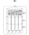
図3は、複数のHDD16と論理ボリュームとの関係性の一例を示す図である。
FIG. 3 is a diagram illustrating an example of the relationship between a plurality of
複数(例えば4台)のHDD16−1、16−2、16−3及び16−4により一つのRAIDグループが構成される。例えば、RAIDレベルがRAID5である場合は、同図のように、データ単位を構成する3つのデータ要素が3つのHDD16に格納され、それら3つのデータを基に生成されたPパリティが、他の一つのHDD16に格納される。
A plurality of (for example, four) HDDs 16-1, 16-2, 16-3, and 16-4 constitute one RAID group. For example, when the RAID level is
このRAIDグループにより提供される記憶領域(4つのHDD16の記憶領域の集合)を、本実施形態では、Virtual Deviceを略して「VDEV」と呼ぶ。このVDEVを区切ることにより得られた各VDEV部分が、本実施形態で言う論理ボリュームである。論理ボリュームは、ホスト4から指定され、ストレージシステム1内部でも識別される。そこで、以下、ホスト4から指定される論理ボリュームを、「LU」(Logical Unit)と称し、ストレージシステム1内部で識別される論理ボリュームを、「LDEV」(Logical Device)と呼ぶ場合がある。この図の例では、一つのVDEVから3つのLDEVが形成されているが、LDEVの数は、それより多くても少なくてもよい(例えば、一つのVDEVに一つのLDEVでもよい)。
In this embodiment, a storage area provided by this RAID group (a set of storage areas of the four HDDs 16) is abbreviated as “VDEV”. Each VDEV portion obtained by dividing this VDEV is a logical volume referred to in this embodiment. The logical volume is designated by the
VDEVは、複数のストライプ列で構成されている。各ストライプ列は、4台のHDD16−1、16−2、16−3及び16−4に対応した4つのストライプで構成されている。HDD16の記憶領域は、複数の所定サイズのサブ記憶領域(つまりストライプ)に区分けられている。ストライプを一つの単位として、データ要素やパリティの書込みが行われる。
VDEV is composed of a plurality of stripe columns. Each stripe row is composed of four stripes corresponding to the four HDDs 16-1, 16-2, 16-3, and 16-4. The storage area of the
以下、図4〜図8を参照して、キャッシュ/制御メモリ14に格納される制御情報に含まれる種々のテーブルを説明する。
The various tables included in the control information stored in the cache /
図4は、RAID構成テーブル400の構成例を示す図である。 FIG. 4 is a diagram illustrating a configuration example of the RAID configuration table 400.
RAID構成テーブル400は、各VDEVのRAID構成を管理するためのテーブルである。具体的には、例えば、このテーブル400には、VDEVの識別番号が書かれるカラム401と、HDDの識別番号が書かれるカラム402と、RAIDレベルが書かれるカラム403と、ストライプサイズ(ストライプの記憶容量)が書かれるカラム404とがある。即ち、このテーブル400には、VDEV毎に、VDEVの識別番号と、該VDEVを構成する複数のHDDの識別番号と、該VDEVのRAIDレベルと、ストライプサイズとが書かれる。
The RAID configuration table 400 is a table for managing the RAID configuration of each VDEV. Specifically, for example, in this table 400, a
図5は、VDEV構成テーブル500の構成例を示す図である。 FIG. 5 is a diagram illustrating a configuration example of the VDEV configuration table 500.
VDEV構成テーブル500は、VDEVの構成を管理するためのテーブルである。具体的には、例えば、このテーブル500には、VDEVの識別番号が書かれるカラム501と、LDEVの識別番号が書かれるカラム502と、LDEVのVDEVにおける論理アドレス範囲の先頭アドレスが書かれるカラム503と、LDEVのVDEVにおける論理アドレス範囲の終端アドレスが書かれるカラム504とがある。即ち、このテーブル500には、どのVDEVのどの論理アドレス範囲にどんな識別番号のLDEVが存在するかが書かれる。
The VDEV configuration table 500 is a table for managing the VDEV configuration. Specifically, for example, in this table 500, a
図6は、LU構成テーブル600の構成例を示す図である。 FIG. 6 is a diagram illustrating a configuration example of the LU configuration table 600.
LU構成テーブル600は、各LUの構成を管理するためのテーブルである。具体的には、例えば、このテーブル600には、LDEVの識別番号が書かれるカラム601と、WWN(World Wide Name)が書かれるカラム602と、LUN(Logical Unit Number)が書かれるカラム603と、LDEVの記憶容量が書かれるカラム604とがある。即ち、このテーブル600には、各LU毎に、LDEVの識別番号と、該LDEVに対応付けられたWWN及びLUNと、そのLDEVの記憶容量とが書かれる。
The LU configuration table 600 is a table for managing the configuration of each LU. Specifically, for example, in this table 600, a
この実施形態では、前述したように、ホスト4から指定される論理ボリュームを「LU」と言うが、具体的には、例えば、Fibre ChannelプロトコルでのWWN及びLUNが対応付けられた論理ボリュームをLUと言う。尚、例えば、メインフレームでは、WWN及びLUNのカラム602及び603は設けられなくてもよい。
In this embodiment, as described above, a logical volume designated by the
図7は、HDD障害チェックテーブル700の構成例を示す図である。 FIG. 7 is a diagram illustrating a configuration example of the HDD failure check table 700.
HDD障害チェックテーブル700は、障害の発生したHDD16をチェックするためのテーブルである。具体的には、例えば、このテーブル700には、HDDの識別番号が書かれるカラム701と、障害が発生しているか否かを識別するためのフラグが書かれるカラム702とがある。即ち、このテーブル700には、どのHDD16に障害が発生しているかが書かれる。
The HDD failure check table 700 is a table for checking the failed
図8は、ストライプ障害チェックテーブル800の構成例を示す図である。 FIG. 8 is a diagram illustrating a configuration example of the stripe failure check table 800.
ストライプ障害チェックテーブル800は、障害の発生したHDD16に含まれるストライプのうち、データ要素を読み出すことができないストライプ(説明の便宜上、「障害ストライプ」と表記する)をチェックするためのテーブルである。このテーブル800は、RAIDグループを構成する全てのHDD16の各々について作成される。具体的には、例えば、このテーブル800には、ストライプの識別番号が書かれるカラム801と、障害が発生しているか否かを識別するためのフラグが書かれるカラム802とがある。即ち、このテーブル800には、どのストライプが障害ストライプであるかが書かれる。尚、同図では、HDD16ごとにそのHDD16に含まれるストライプを一意に特定するために付与された識別番号が、カラム801に書かれているが、図3において付された識別番号のように、RAID内に含まれるストライプを一意に特定するために付与された識別番号が、カラム801に書かれてもよい。
The stripe failure check table 800 is a table for checking a stripe (noted as “failed stripe” for convenience of explanation) from which data elements cannot be read out of stripes included in the
以上が、各種テーブルについての説明である。本実施形態に係るストレージシステム1は、RAID5やRAID6と同様に、RAIDグループを構成する複数のHDD16に分散してデータを書込むストライピングを採用するが、パリティの生成や書き込みについては、RAID5やRAID6とは異なる方法を採用する。以下では、データ要素及びパリティの配置やその配置に基づいて行われるリストアを「データ保護方式」と呼ぶ。本実施形態に係るストレージシステム1は、二種類のデータ保護方式を採用することができる。それら二種類のデータ保護方式のいずれにおいても、二重障害の生じたデータ単位をリストアすることが可能である。具体的には、どのストライプからもデータ要素を読み出すことのできないHDD(以下、完全障害HDD)と、データ要素を読み出せるストライプと読み出せないストライプの両方を有するHDD(以下、一部障害HDD)とが一つのRAIDグループに存在するが故に、読出し不可能な二つのデータ要素を含んだデータ単位である二重障害データが存在する場合、それら二つのデータ要素をリストアすることが可能である。そして、それら二種類のデータ保護方式では、複数のデータ単位に対応した複数のパリティを基にそのトータルサイズよりも小さいサイズの圧縮パリティを生成して格納することで、一つのデータ単位について必ず二つのパリティが生成されるRAID6に比べて、消費記憶容量が少なくて済む。以下、それら二種類のデータ保護方式について具体的に説明する。尚、HDD16へのデータ及びパリティの書込みは、DKA13のCPU131によって実行されるディスクI/O処理部902が行う。また、第一及び第二のデータ保護方式のいずれでも、圧縮パリティが格納されるストライプを、便宜上「特定ストライプ」と言う。一方、データ要素やパリティの書込み先となるストライプを「通常ストライプ」と言う。データ要素或いはパリティの読み出しが不可能になった通常ストライプが、前述した「障害ストライプ」である。
This completes the description of the various tables. The
図9は、第一のデータ保護方式での書込みの説明図である。 FIG. 9 is an explanatory diagram of writing in the first data protection method.
まず、第一のデータ保護方式において、データ要素及びパリティが、HDD15にどのように配置されるかについて説明する。
First, how data elements and parity are arranged in the
第一のデータ保護方式では、HDD16ごとに、HDD16に含まれる全てのストライプのデータ要素及びPパリティから生成された圧縮パリティが書き込まれる。その圧縮パリティは、HDD16に対応する全ての通常ストライプに格納されるデータ要素及びPパリティの排他的論理和を算出することによって(或いは、それらのデータ要素及びPパリティに所定の係数を掛けた後でそれらの排他的論理和を算出することによって)、生成される。圧縮パリティが書き込まれるストライプ(つまり特定ストライプ)の位置は、例えば、同図のように、それぞれのHDD16の最後尾とすることができる。別の言い方をすれば、VDEVの最後尾のストライプ列が、4個の特定ストライプで構成された特定ストライプ列である。尚、特定ストライプは、HDD16の最後尾以外のストライプであっても良い。
In the first data protection method, for each
本実施形態では、4つのHDD16−1乃至16−4にそれぞれ対応した4つの圧縮パリティが、キャッシュ/制御メモリ14のキャッシュ領域に常駐し、適時に、キャッシュ領域から特定ストライプに書き込まれる。例えば、ライト要求を受けた際のデータの書込みにより圧縮パリティが更新された場合、その更新された圧縮パリティは、その更新されたときに、HDD16とキャッシュ領域との両方に書き込まれてもよいし、HDD16には書き込まれずにキャッシュ領域にだけ書き込まれてもよい。後者の場合は、その後の所定のタイミングで、キャッシュ領域に書き込まれている4つの圧縮パリティのうちの少なくとも一つ(例えば、全て、或いは、更新された圧縮パリティのみ)が、HDD16における特定ストライプにコピーされる。このようにすることで、ライト要求を受けた際のデータの書込みを行う度に、HDD16上の圧縮パリティが書き込まれているストライプへのアクセスが行われなくなるので、書込みに要する時間が短縮される。HDD16−1を例に採り説明すると、HDD16−1における通常ストライプに書き込まれるデータ要素及びPパリティ(データ要素“0”、
“3”及び“6”とPパリティ“P3”など)を基に、HDD16−1に対応する圧縮パリティ“RP0”が生成され、それが、キャッシュ領域とHDD16−1に書き込まれる。他のHDD16−2〜16−4における圧縮パリティ“RP1”〜“RP3”の生成及び書き込みについても、HDD16−1における圧縮パリティ“RP0”の場合と同様である。
In this embodiment, four compressed parities respectively corresponding to the four HDDs 16-1 to 16-4 are resident in the cache area of the cache /
Based on “3” and “6” and the P parity “P3”, etc., a compressed parity “RP0” corresponding to the HDD 16-1 is generated and written to the cache area and the HDD 16-1. The generation and writing of the compressed parities “RP1” to “RP3” in the other HDDs 16-2 to 16-4 are the same as in the case of the compressed parity “RP0” in the HDD 16-1.
第一のデータ保護方式は、圧縮パリティが書き込まれる点を除いては、RAID5におけるデータ保護方式と実質的に同じである。従って、同図のように、RAIDグループを構成するHDD16の総数が4つである場合は、そのうちの3つのHDD16に、データ単位を構成する3つのデータ要素(例えば、データ要素“0”、“1”及び“2”)が書き込まれ、残りの一つのHDDに、そのデータ単位に基づく一つのPパリティ(例えば、Pパリティ“P0”)が書き込まれる。つまり、RAIDグループを構成するHDD16の個数をN(Nは3以上の整数)とすると、(N−1)個のHDD16それぞれに1個の、即ち(N−1)個のHDD16に対して合計(N−1)個のデータ要素が書き込まれ、残りの1個のHDD16に、それら(N−1)個のデータ要素を基に生成された一つのPパリティが書き込まれる。Pパリティは、4つのHDD16−1〜16−4に分散して書き込まれる。言い換えれば、Pパリティの書込み先となるHDD16は、データ単位毎にシフトする。
The first data protection method is substantially the same as the data protection method in
次に、第一のデータ保護方式に従う、データ単位及びPパリティの更新について説明する。なお、以下の説明では、更新前のデータ要素を、「旧データ要素」と言い、更新後のデータ要素を、「新データ要素」と言う(Pパリティ及び圧縮パリティについても同様)。 Next, updating of data units and P parity according to the first data protection method will be described. In the following description, the data element before update is referred to as “old data element”, and the data element after update is referred to as “new data element” (the same applies to P parity and compressed parity).
例えば、1番目のデータ単位を構成する3つのデータ要素のうちデータ要素“1”が更新されるとする。この場合、Pパリティ“P0”及び圧縮パリティ“RP1”を更新する必要がある。なぜなら、Pパリティ“P0”も圧縮パリティ“RP1”も、旧データ要素“1”を基に生成されたパリティであって、データ要素“1”が更新されれば、Pパリティ“P0”及び圧縮パリティ“RP1”の値が変わるためである。 For example, it is assumed that the data element “1” is updated among the three data elements constituting the first data unit. In this case, it is necessary to update the P parity “P0” and the compressed parity “RP1”. This is because both the P parity “P0” and the compressed parity “RP1” are generated based on the old data element “1”. If the data element “1” is updated, the P parity “P0” and the compressed parity are compressed. This is because the value of the parity “RP1” changes.
そこで、ディスクI/O処理部902は、まず、Pパリティ“P0”の生成に必要となる旧データ要素“1”及び旧Pパリティ“P0”を、HDD16−2及び16−4から読み出す。そして、ディスクI/O処理部902は、新データ要素“1”と、旧データ要素“1”及び旧Pパリティ“P0”とを基に、新Pパリティ“P0”を生成することができる(或いは、更新されないデータ要素“0”及び“2”と、新データ要素“1”とから、新Pパリティ“P0”を生成してもよい)。また、ディスクI/O処理部902は、新Pパリティ“P0”の生成と同じような方法で、新圧縮パリティ“RP1”の生成も行う。即ち、ディスクI/O処理部902は、HDD16−2に対応した旧圧縮パリティ“RP1”と、旧データ要素“1”、新データ要素“1”とを基に、新圧縮パリティ“RP1”を生成することができる(或いはディスクI/O処理部902は、HDD16−2から、旧データ要素“1”以外のデータ要素とPパリティを読出し、読み出したデータ要素及びPパリティと、新データ要素“1”とを基に、新圧縮パリティ“RP1”を生成しても良い)。その後、ディスクI/O処理部902は、新データ要素“1”を、旧データ要素“1”が記憶されている通常ストライプに書き込み、新Pパリティ“P0”を、旧Pパリティ“P0”が記憶されている通常ストライプに書き込む。また、ディスクI/O処理部902は、新圧縮パリティ“RP1”を、キャッシュ領域に書込み、所定のタイミングで、キャッシュ領域上の新圧縮パリティ“RP1”を、旧圧縮パリティ“RP1”が記憶されている特定ストライプに書き込む。
Therefore, the disk I /
図10は、第一のデータ保護方式でのリストアの説明図である。なお、以下の説明では、読出し不可能なデータ要素が一つだけであるデータ単位であって、二重障害データ(前述した通り、読出し不可能なデータ要素を二つ含んだデータ単位)ではないデータ単位のことを、「一重障害データ」と言う。 FIG. 10 is an explanatory diagram of restoration by the first data protection method. In the following description, it is a data unit that has only one data element that cannot be read, and is not double failure data (a data unit that includes two data elements that cannot be read as described above). The data unit is called “single failure data”.
同図では、HDD16−1が、完全障害HDDであり、HDD16−2が、一部障害HDDである。その一部障害HDD16−2では、データ要素“13”を記憶した通常ストライプが障害ストライプである。 In the figure, the HDD 16-1 is a completely failed HDD, and the HDD 16-2 is a partially failed HDD. In the partially failed HDD 16-2, the normal stripe storing the data element “13” is the failed stripe.
一重障害データを構成するデータ要素のリストアの手順は、通常のRAID5と同様である。すなわち、完全障害HDD16−1の障害ストライプに記憶されている、一重障害データを構成するデータ要素は、その一重障害データを構成する他の全てのデータ要素と、その一重障害データに対応したPパリティとを用いて(言い換えれば、その障害ストライプを含んだストライプ列における他の全てのストライプにあるデータ要素及びPパリティを用いて)、リストアされる。 The procedure for restoring the data elements constituting the single failure data is the same as that for normal RAID5. That is, the data elements constituting the single fault data stored in the fault stripe of the completely faulty HDD 16-1 are all other data elements constituting the single fault data and the P parity corresponding to the single fault data. (In other words, using data elements and P parity in all other stripes in the stripe column containing the failing stripe).
一方、二重障害データを構成する読み出し不可能な二つのデータ要素は、通常のRAID5と同様の手順でリストアすることはできない。二重障害データに対応するパリティは一つだけだからである。本例の場合では、データ要素“12”と“13”の両方を、残りのデータ要素“14”とPパリティ“P4”とからだけでは、リストアすることはできない。 On the other hand, the two unreadable data elements that make up the double failure data cannot be restored in the same procedure as in normal RAID5. This is because there is only one parity corresponding to double failure data. In this example, it is not possible to restore both data elements “12” and “13” only from the remaining data element “14” and P parity “P4”.
そこで、これら二つのデータ要素のリストアは、圧縮パリティを利用して、次のようにして行われる。 Therefore, the restoration of these two data elements is performed as follows using the compressed parity.
まず、一部障害HDD16−2における障害ストライプに記憶されているデータ要素“13”がリストアされる。具体的には、一部障害HDD16−2における、障害ストライプ以外の全ての通常ストライプに記憶されているデータ要素及びPパリティと、その一部障害HDD16−2に対応した圧縮パリティ“RP1”(キャッシュ領域又は特定ストライプに記憶されている圧縮パリティ“RP1”)との排他的論理和により、データ要素“13”がリストアされる(同図の(a))。 First, the data element “13” stored in the failed stripe in the partially failed HDD 16-2 is restored. Specifically, in the partially failed HDD 16-2, the data elements and P parity stored in all the normal stripes other than the failed stripe, and the compressed parity “RP1” (cache) corresponding to the partially failed HDD 16-2. The data element “13” is restored by exclusive OR with the compressed parity “RP1” stored in the area or the specific stripe ((a) in FIG. 6).
次に、そのデータ要素“13”と、そのデータ要素“13”を含んだデータ単位における他のデータ要素“14”及びそのデータ単位に対応したPパリティ“P4”を基に、完全障害HDD16−1の障害ストライプに記憶されている、データ要素“12”がリストアされる。これにより、二重障害データにおけるデータ要素“12”及び“13”の両方がリストアされたことになる。 Next, based on the data element “13”, another data element “14” in the data unit including the data element “13”, and the P parity “P4” corresponding to the data unit, the completely failed HDD 16- The data element “12” stored in one failure stripe is restored. As a result, both of the data elements “12” and “13” in the double failure data are restored.
最後に、完全障害HDD16−1の特定ストライプに記憶される、圧縮パリティがリストアされる。具体的には、完全障害HDD16−1の障害ストライプに記憶されている、二重障害データにおけるリストアされたデータ要素“12”や、RAID5と同様にリストアされた他のデータ要素やPパリティを基に、圧縮パリティ“RP1”がリストアされる。
Finally, the compressed parity stored in the specific stripe of the completely failed HDD 16-1 is restored. Specifically, based on the restored data element “12” in the double fault data stored in the fault stripe of the completely faulty HDD 16-1, other data elements restored in the same manner as
以上が、第一のデータ保護方式についての説明である。 The above is the description of the first data protection method.
なお、上記の処理において、一部障害HDDの障害ストライプに、データ要素ではなくPパリティが記憶されている場合には、その一部障害HDDに対応した圧縮パリティや、その一部障害HDDの障害ストライプ以外の通常ストライプに記憶されているデータ要素及びPパリティを基に、その障害ストライプに記憶されているPパリティがリストアされる。そして、そのリストアされたPパリティを用いて、通常のRAID5と同様の方法で、完全障害HDDの障害ストライプに記憶されているデータ要素がリストアされる。 In the above processing, when P parity is stored in the failure stripe of the partially failed HDD instead of the data element, the compressed parity corresponding to the partially failed HDD or the failure of the partially failed HDD is stored. Based on the data element and P parity stored in the normal stripe other than the stripe, the P parity stored in the failed stripe is restored. Then, by using the restored P parity, the data element stored in the failed stripe of the completely failed HDD is restored by the same method as in normal RAID5.
また、上記の説明によれば、第一のデータ保護方式では、完全障害HDD以外の全てのHDDが、一部障害HDDであっても良い。但し、一部障害HDDに記憶されているデータ要素をリストアするためには、一部障害HDDに存在する障害ストライプは一つだけである必要がある。 Further, according to the above description, in the first data protection method, all HDDs other than the completely failed HDD may be partially failed HDDs. However, in order to restore a data element stored in the partially failed HDD, it is necessary that only one failed stripe exists in the partially failed HDD.
また、第一のデータ保護方式では、一つのデータ単位及びそれに対応するPパリティのトータルサイズと、一つのストライプ列のサイズとが同一である。具体的には、一つのデータ単位及びそれに対応するPパリティは、一つのストライプ列に収まり、複数のストライプ列に跨ることは無い。しかし、それに限らず、例えば、後述する第二のデータ保護方式の例と同様に、一つのデータ単位及びそれに対応するPパリティのトータルサイズは、一つのストライプ列のサイズより小さくても良い。 In the first data protection method, the total size of one data unit and the corresponding P parity and the size of one stripe column are the same. Specifically, one data unit and the corresponding P parity are contained in one stripe column and do not straddle a plurality of stripe columns. However, the present invention is not limited to this. For example, as in the example of the second data protection method described later, the total size of one data unit and the corresponding P parity may be smaller than the size of one stripe column.
図11は、第二のデータ保護方式での書込みの説明図である。 FIG. 11 is an explanatory diagram of writing in the second data protection method.
第二のデータ保護方式では、第一のデータ保護方式と異なり、一つのデータ単位について、RAID6と同様に、PパリティのみならずQパリティ(第二の冗長コード)も生成される。しかし、データ単位毎にRAIDグループに書き込まれるのは、Qパリティのみであって、Pパリティは、データ単位毎には書き込まれない。Pパリティに関して言えば、複数のデータ単位に対応した複数のPパリティが一つの圧縮パリティに圧縮されてRAIDグループに書き込まれる。これにより、二重障害データにおける二つのデータ要素のリストアを可能にしつつ、RAIDグループの消費記憶容量の節約も可能にする。
Unlike the first data protection method, the second data protection method generates not only P parity but also Q parity (second redundancy code) for one data unit, as in
第二のデータ保護方式では、RAIDグループを構成するHDD16の個数をNとすると、(N−2)個のストライプにデータが書き込まれ、残り2個のHDD16のうちのどちらか1個に含まれるストライプに、Qパリティが書き込まれる。つまり、第二のデータ保護方式では、データ単位とQパリティとのトータルデータサイズよりも、一ストライプ列のサイズの方が、ストライプ一つ分大きいことになる。
In the second data protection method, when the number of
第二のデータ保護方式では、前述したように、特定ストライプに書き込まれる圧縮パリティは、複数のデータ単位に対応する複数のPパリティを一つに圧縮したコード、具体的には、それら複数のPパリティの排他的論理和をとることによって生成される。本実施形態では、例えば、3つのデータ単位に対応する3つのPパリティを基に一つの圧縮コードが生成される。具体的には、例えば、第一のデータ単位に対応した第一のPパリティ(データ要素“0”及び“1”の排他的論理和)と、第二のデータ単位に対応した第二のPパリティ(データ要素“48”及び“49”の排他的論理和)と、第三のデータ単位に対応した第三のPパリティ(データ要素“96”及び“97”の排他的論理和)との排他的論理和を算出することにより、圧縮パリティ“CP0”が生成される。 In the second data protection method, as described above, the compressed parity written in the specific stripe is a code obtained by compressing a plurality of P parities corresponding to a plurality of data units into one, specifically, the plurality of P parities. It is generated by taking the exclusive OR of parity. In the present embodiment, for example, one compressed code is generated based on three P parities corresponding to three data units. Specifically, for example, a first P parity (exclusive OR of data elements “0” and “1”) corresponding to the first data unit and a second P corresponding to the second data unit. Parity (exclusive OR of data elements “48” and “49”) and third P parity (exclusive OR of data elements “96” and “97”) corresponding to the third data unit The compressed parity “CP0” is generated by calculating the exclusive OR.
第二のデータ保護形式では、一つのHDD16に、複数の特定ストライプが存在する。このため、HDEVには、複数の特定ストライプ列が存在することになる。複数の特定ストライプ列は、HDEVに分散していても良いが、図示のように、HDEVの末尾側に、連続した特定ストライプ列として存在しても良い。
In the second data protection format, a plurality of specific stripes exist in one
本実施形態における第二のデータ保護方式では、以下の第一及び第二の規則が遵守される。 In the second data protection method in this embodiment, the following first and second rules are observed.
第一の規則は、圧縮パリティを、それの基になった複数のPパリティに対応する複数のデータ単位及びそれら複数のデータ単位に対応する複数のQパリティが記憶されるHDDと異なるHDD16のストライプに書き込むことである。HDD16の障害の発生により、圧縮パリティと、それに対応する各データ単位におけるデータ要素又は各データ単位に対応するQパリティとが、同時に読み出せなくなることを避けるためである。例えば、圧縮パリティ“CP0”について説明すると、圧縮パリティ“CP0”に対応したデータ単位を構成する二つのデータ要素がHDD16−1及び16−2に書き込まれ、そのデータ単位に対応するQパリティがHDD16−3に書き込まれるため、圧縮パリティ“CP0”は、HDD16−4に書き込まれる。別の言い方をすれば、HDD16−4に書き込まれる圧縮パリティの基にすべき複数のPパリティに対応する複数のデータ単位は、HDD16−1及び16−2に書き込まれるデータ単位とすべきである。なぜなら、そのデータ単位に対応するQパリティの書込み先はHDD16−3であり、重複しないHDDはHDD16−4のみだからである。
The first rule is that the stripe of the
第二の規則は、圧縮パリティに対応するm番目のデータ単位及びそれのQパリティと、その圧縮パリティに対応するm+1番目のデータ単位及びそれのQパリティ(つまり次のデータ単位及びそれのQパリティ)との間に、所定数の通常ストライプが存在することである。別の言い方をすれば、第二の規則は、圧縮パリティに対応するm番目のデータ単位及びそれのQパリティが存在する一つ又は二つの通常ストライプ列と、m+1番目のデータ単位及びそれのQパリティが存在する一つ又は二つの通常ストライプ列との間に、所定数の通常ストライプ列が存在することである。従って、例えば、圧縮パリティ“CP0”について言えば、圧縮パリティ“CP0”に対応するデータ単位は、HDD16−1及び16−2にわたって記憶されるデータ単位であれば何でも良いわけではなく、HDD16−1及び16−2にわたって記憶されるデータ単位であって、所定数の通常ストライプ列を隔てたデータ単位同士である必要がある。なぜなら、詳細は後述するが、圧縮パリティに対応する複数のデータ単位において二重障害データが一つだけであれば、その二重障害データを構成する読出し不可能な二つのデータ要素をリストアすることができるが、それら複数のデータ単位に二重障害データが二つ以上あると、リストアが不可能となってしまうためである。 The second rule is that the mth data unit corresponding to the compressed parity and its Q parity, the m + 1st data unit corresponding to the compressed parity and its Q parity (ie, the next data unit and its Q parity). ) Is a predetermined number of normal stripes. In other words, the second rule is that the mth data unit corresponding to the compressed parity and one or two normal stripe columns in which the Q parity exists, and the m + 1th data unit and its Q That is, there is a predetermined number of normal stripe columns between one or two normal stripe columns in which parity exists. Therefore, for example, with regard to the compressed parity “CP0”, the data unit corresponding to the compressed parity “CP0” is not limited to any data unit stored across the HDDs 16-1 and 16-2. And 16-2, the data units must be data units separated by a predetermined number of normal stripe columns. This is because, as will be described later in detail, if there is only one double failure data in a plurality of data units corresponding to the compressed parity, the two unreadable data elements constituting the double failure data are restored. However, if there are two or more double failure data in the plurality of data units, restoration is impossible.
第二のデータ保護方式によれば、一つの圧縮パリティに対応するデータ単位の数が多ければ多いほど、RAIDグループに書き込まれる圧縮パリティの数を減らすことができる。しかし、そうすると、データ単位間の間隔が短くなる。すなわち、データ単位及びそれに対応するQパリティと、次のデータ単位及びQパリティとの間に存在するストライプの数が少なくなる(言い換えれば、それらのデータ単位が存在するストライプ列同士の間に存在するストライプ列数が少なくなる)。データ単位間の間隔が狭いと、完全障害HDDが一つ存在し更に別のHDD16で障害が生じたことにより一つの部分障害HDDが生じた場合に、圧縮パリティに対応する複数のデータ単位のうちの二以上のデータ単位が同時に二重障害データとなってしまうおそれがある。これを避ける方法としては、圧縮パリティに対応するデータ単位の数を少なくし、且つ、圧縮パリティに対応するデータ単位とデータ単位との間隔を十分に長くする方法が考えられる。しかし、そうすると、RAIDグループに書き込まれる圧縮パリティの数が多くなる。この観点から、本実施形態では、圧縮パリティに対応するデータ単位とデータ単位との間隔を、各HDD16のハードディスクの構造(例えば、記録密度)を基に適切な長さに設定されている。このため、例えば、RAIDグループを構成する複数のHDDのハードディスクの構造は同じである。
According to the second data protection method, the greater the number of data units corresponding to one compressed parity, the more the number of compressed parity written in the RAID group can be reduced. However, doing so shortens the interval between data units. That is, the number of stripes existing between a data unit and the corresponding Q parity and the next data unit and Q parity is reduced (in other words, between the stripe columns in which those data units exist). Fewer stripe columns). When the interval between data units is narrow, when one partially failed HDD is generated due to the presence of one completely failed HDD and a failure in another
図12は、第二のデータ保護方式での書込みをより詳細に説明するための図である。 FIG. 12 is a diagram for explaining writing in the second data protection method in more detail.
同図の例では、8つのHDD16−1〜16−8からRAIDグループが構成されている。上述したように、それぞれのHDD16の記憶領域は、複数のストライプに区分けされている。番号が付与されている一つの領域が、一つのストライプである。本例では、図3や図9乃至図11の場合と異なり、各ストライプに記録されている番号は、データ要素或いはパリティの識別番号ではなく、データ単位を識別する識別番号である。但し、Qパリティには、その識別番号の前に「Q」の文字が付与されているため、どのデータ単位に対応するQパリティであるかがわかるようになっている。
In the example of the figure, a RAID group is composed of eight HDDs 16-1 to 16-8. As described above, the storage area of each
圧縮パリティ“CP0”に対応するデータ単位及びQパリティと次のデータ単位及びQパリティとの間には、i個の他のデータ単位が存在する。iは、上述した第二の規則に基づく1以上の整数である。なお、iの選定基準については後述する。圧縮パリティ“CP0”は、データ単位“0”、“i”、“2i”、“3i”、…(その他このRAIDグループに含まれる全てのストライプ列のうち、その識別番号がiの倍数となるもの)に対応している。具体的には、データ単位“0”のPパリティをPパリティ“P0”、データ単位“i”のPパリティをPパリティ“Pi”、データ単位“2i”のPパリティをPパリティ“P2i”とする。また、圧縮パリティ“CP0”に対応する、データ単位“3i”以降の全てのデータ単位に対応する全てのPパリティの排他的論理和を算出した値を、“Px”とする。そうすると、圧縮パリティ“CP0”は、P0とPiとP2iとPxとの排他的論理和となる。圧縮パリティ“CP0”は、第一の規則に従い、それの基になったデータ単位及びQパリティのいずれも書き込まれないHDD16−8に書き込まれる。 There are i other data units between the data unit and Q parity corresponding to the compressed parity “CP0” and the next data unit and Q parity. i is an integer of 1 or more based on the second rule described above. The selection criteria for i will be described later. The compressed parity “CP0” has data units “0”, “i”, “2i”, “3i”,... (Other identification numbers of all stripe columns included in this RAID group are multiples of i. Stuff). Specifically, the P parity of the data unit “0” is P parity “P0”, the P parity of the data unit “i” is P parity “Pi”, and the P parity of the data unit “2i” is P parity “P2i”. To do. Further, a value obtained by calculating an exclusive OR of all P parities corresponding to all data units subsequent to the data unit “3i” corresponding to the compressed parity “CP0” is defined as “Px”. Then, the compressed parity “CP0” is an exclusive OR of P0, Pi, P2i, and Px. The compressed parity “CP0” is written to the HDD 16-8 in accordance with the first rule, in which neither the data unit that is the basis of the compressed parity nor the Q parity is written.
他の圧縮パリティについても、圧縮パリティ“CP0”と実質的に同様に生成され書き込まれる。例えば、圧縮パリティ“CP6”は、データ単位“6”に対応したPパリティ“P6”と、データ単位“i+6”に対応したPパリティ“Pi+6”と、データ単位“2i+6”に対応したPパリティ“P2i+6”と、データ単位“3i+6”以降のデータ単位に対応したPパリティの排他的論理和である値“Py”との排他的論理和である。この圧縮パリティ“CP6”は、第一の規則に従い、それの基になったデータ単位及びQパリティのいずれも書き込まれないHDD16−2に書き込まれる。 Other compressed parities are also generated and written in substantially the same manner as the compressed parity “CP0”. For example, the compressed parity “CP6” includes a P parity “P6” corresponding to the data unit “6”, a P parity “Pi + 6” corresponding to the data unit “i + 6”, and a P parity “corresponding to the data unit“ 2i + 6 ”. P2i + 6 ”is an exclusive OR of a value“ Py ”that is an exclusive OR of P parities corresponding to data units“ 3i + 6 ”and subsequent data units. The compressed parity “CP6” is written to the HDD 16-2 in accordance with the first rule, in which neither the data unit or the Q parity that is the basis thereof is written.
図13は、第二のデータ保護方式でのリストアの説明図である。 FIG. 13 is an explanatory diagram of restoration by the second data protection method.
第二のデータ保護方式でも、第一のデータ保護方式と同様、二重障害データにおける読出し不可能な二つのデータ要素をリストアすることができるが、その際、リストア可能な、一部障害HDDに関する条件が異なる。すなわち、第一のデータ保護方式では、完全障害HDD以外のどのHDDも一部障害HDDであっても良いが、各一部障害HDDに存在しても良い障害ストライプは一つである。それに対し、第二のデータ保護方式では、一つのRAIDグループに存在しても良い一部障害HDDは一つだけであるが、その一部障害HDDに存在しても良い障害ストライプは、一つに限らない。但し、一つの圧縮パリティに対応する複数のデータ単位に存在しても良い二重障害データは一つだけである。 Similarly to the first data protection method, the second data protection method can restore two data elements that cannot be read in the double failure data. The conditions are different. That is, in the first data protection method, any HDD other than the completely failed HDD may be a partially failed HDD, but there is one failed stripe that may exist in each partially failed HDD. In contrast, in the second data protection method, only one partially failed HDD may exist in one RAID group, but only one failed stripe may exist in the partially failed HDD. Not limited to. However, only one double failure data may exist in a plurality of data units corresponding to one compressed parity.
同図では、HDD16−1が完全障害HDDであり、HDD16−2が、一部障害HDDである。HDD16−2には、圧縮パリティ“CP0”に対応した複数のデータ単位のうち、データ単位“0”のみが二重障害データとなり、他のデータ単位(“i”、“2i”、“3i”・・・)一重障害データとならない範囲で、障害ストライプが存在する。 In the figure, the HDD 16-1 is a completely failed HDD, and the HDD 16-2 is a partially failed HDD. In the HDD 16-2, only the data unit “0” among the plurality of data units corresponding to the compressed parity “CP0” becomes double failure data, and other data units (“i”, “2i”, “3i”). ...) Fault stripes exist within a range that does not result in single fault data.
圧縮パリティ“CPx”(xは整数)に対応するデータ単位と次のデータ単位との間隔を示す値“i”について、その選定例を説明する。図23はHDD16内の記憶媒体(磁気円盤)上におけるデータ(セクタ)の配置例と、記憶媒体上に部分障害が発生した場合の障害範囲とを示した図である。1,2,3,…の番号が割り振られている領域は、「セクタ」と呼ばれる固定長(一般的なハードディスクでは512バイト)の領域である。HDD16内の記憶媒体上には、セクタが同心円状に複数個配置される。同心円の1周分のセクタの集合を「トラック」と呼ぶ。また図23において、点線の楕円で示している領域は、記憶媒体上の部分障害の発生箇所の例である。一般に、記憶媒体上の部分障害が発生する場合、障害の発生したセクタの配置される1つのトラックを観測すると、障害の範囲は、トラック内の1セクタ分に収まる。ただし、この障害の範囲は、複数のトラック(一般的に10トラック程度)に跨ることが多い。そのため、圧縮パリティ“CPx”に対応するデータ単位と次のデータ単位との間隔を設定する際に、この部分障害の特性を考慮する。
An example of selecting the value “i” indicating the interval between the data unit corresponding to the compressed parity “CPx” (x is an integer) and the next data unit will be described. FIG. 23 is a diagram showing an arrangement example of data (sectors) on a storage medium (magnetic disk) in the
図12と図23とに基づいて更に説明する。図12において、1つのストライプのサイズが4KB(キロバイト)とすると、HDD16−1の1ストライプ、例えばストライプ0は、図23に示した記憶媒体上の8セクタ分の大きさ、即ち、セクタ1からセクタ8に対応する。図23に示したセクタ配置例では、1トラック上に16セクタ、即ち8KBのセクタが配置されるため、1トラック上に、2ストライプが配置される。即ち、図12のストライプ0及び1が、最初のトラック(最外周のトラック)に、そして、ストライプ2及び3が、次の周のトラックに、それぞれ配置されることになる。圧縮パリティ“CP0”の生成には、ストライプ0とストライプ“i”及びストライプ“2i”が使用される。圧縮パリティに基づいて、データリストアをする場合、圧縮パリティを生成するために使用するストライプのうち、1つのストライプが障害の場合には、リストアが可能だが、そうでない場合には、リストアは不可能になる。図23に示した記憶媒体上の部分障害の範囲が、ほとんどの場合、10トラック以内に収まるとすると、本文における例、即ち1トラック上に2ストライプが配置される例の場合には、ストライプ0とストライプ“i”(あるいはストライプ“i”とストライプ“2i”なども同様)の間隔を、5トラックよりも多く離して配置する。これにより、部分障害が発生したときに、ストライプ0とストライプ“i”とが同時にアクセス不可(読めなくなる)になることを回避することができる(正確には、同時にアクセスできなくなる確率を低くすることが出来る)。そのため、この場合には、iを、5以上に設定すると良い。
Further description will be given based on FIG. 12 and FIG. In FIG. 12, if the size of one stripe is 4 KB (kilobytes), one stripe of HDD 16-1, for example,
第二のデータ保護方式でのリストアの手順の概要は、以下の通りである。 The outline of the restoration procedure in the second data protection method is as follows.
まず、完全障害HDD16−1の障害ストライプに記憶されている、各一重障害データにおける各データ要素が、各一重障害データに対応するQパリティを用いてRAID5と同様の手法でリストアされる(同図(a))。なお、データ要素の代わりにQパリティが記憶されている場合には、一重障害データとすらなっていない通常のデータ単位を基にQパリティがリストアされる。
First, each data element in each single fault data stored in the fault stripe of the completely faulty HDD 16-1 is restored by the same method as
次に、各圧縮パリティについて、圧縮パリティに対応する複数のデータ単位における二重障害データに対応するPパリティがリストアされる(同図(b))。具体的には、例えば、圧縮パリティ“CP0”と、それの基になった、二重障害データ“0”に対応するPパリティ“P0”以外のパリティ“Pi”、“P2i”及び“Px”を基に、二重障害データ“0”に対応するPパリティ“P0”がリストアされる。 Next, for each compressed parity, the P parity corresponding to the double failure data in the plurality of data units corresponding to the compressed parity is restored ((b) in the figure). Specifically, for example, the compressed parity “CP0” and the parity “Pi”, “P2i”, and “Px” other than the P parity “P0” corresponding to the double failure data “0” based on the compressed parity “CP0”. Based on this, the P parity “P0” corresponding to the double failure data “0” is restored.
その後、RAID6と同様の手法により、二重障害データにおける二つのデータ要素がリストアされる(同図(c))。具体的には、リストアされたPパリティ“P0”と、二重障害データ“0”に対応するQパリティとを基に、二重障害データ“0”における読出し不可能な二つのデータ要素(完全障害HDD16−1と一部障害HDD16−2とに記憶されているデータ要素)がリストアされる。 Thereafter, the two data elements in the double failure data are restored by the same method as in RAID 6 ((c) in the figure). Specifically, based on the restored P parity “P0” and the Q parity corresponding to the double failure data “0”, two unreadable data elements in the double failure data “0” (completely The data elements stored in the failed HDD 16-1 and the partially failed HDD 16-2) are restored.
最後に、完全障害HDD16−1の各特定ストライプに記憶されている各圧縮パリティがリストアされる(同図(d))。具体的には、例えば、同図(a)乃至(c)により、全ての二重障害データが通常のデータ単位にリストアされたので、リストアされた通常のデータ単位を基にPパリティを生成し、生成したPパリティと、そのデータ単位が対応する圧縮パリティに対応する他のデータ単位に対応するPパリティとを基に、完全障害HDD16−1に記憶されている圧縮パリティ“CP7”、“CP15”などがリストアされる。 Finally, each compressed parity stored in each specific stripe of the completely failed HDD 16-1 is restored ((d) in the figure). Specifically, for example, as shown in (a) to (c) of FIG. 5, since all the double-failure data has been restored to the normal data unit, the P parity is generated based on the restored normal data unit. Based on the generated P parity and the P parity corresponding to another data unit corresponding to the compressed parity corresponding to the data unit, the compressed parity “CP7”, “CP15” stored in the complete failure HDD 16-1 "Etc. are restored.
以上が、第一及び第二のデータ保護形式についての説明である。なお、いずれのデータ保護方式においても、完全障害HDDや一部障害HDDについて、一重障害データや二重障害データにおける読出し不可能なデータ要素は、所定の記憶資源、例えばスペアのHDDにリストアされる。 This completes the description of the first and second data protection formats. In any data protection method, for a completely failed HDD or a partially failed HDD, unreadable data elements in single failed data or double failed data are restored to a predetermined storage resource, for example, a spare HDD. .
以下、本実施形態で行われる種々の処理の流れを説明する。 Hereinafter, the flow of various processes performed in the present embodiment will be described.
図14は、ストレージシステム1がホスト4からI/O要求を受信した場合にコマンド処理部901が行う処理のフローチャートである。
FIG. 14 is a flowchart of processing performed by the
ホスト4は、LUにアクセスする際、LUに付与されているWWNとLUN、そして、リード乃至ライト対象のアドレス(LBA:Logical Block Address)を指定したI/O要求を、ストレージシステム1に対して発行する。コマンド処理部901は、そのI/O要求を受けたことに応答して、LU構成テーブル600を参照し、LUNとWWNに対応するLDEVの識別番号(LDEV番号)を割り出す(S101)。続いて、コマンド処理部901は、ホスト4からのI/O要求がライト要求であるか否かを判定する(S102)。ライト要求の場合には(S102:YES)、本処理はS103に移行し、そうでない場合(リード要求)には(S102:NO)、本処理はS105へと移行する。
When accessing the LU, the
S103では、コマンド処理部901は、キャッシュ/制御メモリ14のキャッシュ領域の未使用領域にライトデータ(I/O要求に従うライト対象のデータ)を格納し、S104で、ホスト4に対して、当該ライト処理が完了したことを通知する。S104の処理は、これよりも後、例えばS105の後に行ってもよい。S104の時点ではHDD16へのデータ書き込みは完了していないが、キャッシュ領域にライトデータが格納された時点で、ホスト4に対して処理完了を通知することで、ライト処理の応答時間を高速化することが出来る。
In S103, the
S105では、コマンド処理部901は、RAID構成テーブル400及びVDEV構成テーブル500を参照し、S101で割り出したLDEV番号の付与されたLDEVを含むVDEVのRAIDレベルを判定する。
In S105, the
RAIDレベルの値が「0x0b」の場合は(S105:YES)、コマンド処理部901は、第一のデータ保護方式に基づいて、S101で割り出したLDEV番号の付与されたLDEVに対するリード乃至ライト処理を実施する(S106)。この処理については、図15で詳述する。
When the value of the RAID level is “0x0b” (S105: YES), the
一方、RAIDレベルの値が「0x0a」である場合は(S105:NO)、コマンド処理部901は、第二のデータ保護方式に基づいて、S101で割り出したLDEV番号の付与されたLDEVに対するリード乃至ライト処理を実施する(S107)。この処理については、図18、19で詳述する。
On the other hand, when the value of the RAID level is “0x0a” (S105: NO), the
S108で、コマンド処理部901は、受信したI/O要求がリード要求であるかを判定する。当該要求がリード要求である場合(S108:YES)、前述のS106又はS107の処理によって、HDD16からのリード対象のデータがキャッシュ領域に格納されているので、コマンド処理部901は、キャッシュ領域上のリード対象のデータをホスト4に対して返送する(S109)。S108で、当該要求がリード要求ではないと判断された場合には(S108:NO)、本処理は終了する。
In step S108, the
図15は、第一のデータ保護方式に基づいたI/O処理のフローチャートである。 FIG. 15 is a flowchart of the I / O processing based on the first data protection method.
図15の説明では、I/O要求の対象とされたLDEVを「対象LDEV」と言い、対象LDEVを含むVDEVに属する各HDDを「対象HDD」と言い、ホスト4からのI/O要求で指定されているLBAで特定されるボリューム領域が対応付けられるHDD上のアドレスを「対象物理アドレス」と呼ぶ。
In the description of FIG. 15, the LDEV targeted for the I / O request is referred to as “target LDEV”, each HDD belonging to the VDEV including the target LDEV is referred to as “target HDD”, and the I / O request from the
S201では、ホスト4からのI/O要求で指定されているLBAが対象物理アドレスに変換される。具体的には、例えば、コマンド処理部901が、DKA13に、ホスト4からのI/O要求で指定されているLBAを含んだI/O要求を出し、DKA13内のディスクI/O処理部902が、そのI/O要求を受ける。そのI/O要求は、キャッシュ/制御メモリ14の制御領域に書かれてもよいし、内部スイッチ15を介してDKA13に送信されてもよい。I/O要求を受けるDKA13は、各対象HDD16に接続されたDKA13である。当該DKA13のディスクI/O処理部902が、受けたI/O要求中のLBAを対象物理アドレスに変換する。
In S201, the LBA specified by the I / O request from the
S202では、ディスクI/O処理部902が、受けたI/O要求が、ライト要求であるかリード要求であるかを判断する。ライト要求である場合には(S202:YES)、本処理はS203に移行し、リード要求である場合には(S202:NO)、本処理はS208に移行する。尚、このS202の処理は、S201の処理が終了する前に完了されてもよい。
In S202, the disk I /
S203では、ディスクI/O処理部902が、キャッシュ領域上に置かれたライト対象のデータの書込みに関係するストライプ(例えば、ライト対象のデータから分割される各データ単位、各データ単位に関連するPパリティ、或いは、更新される圧縮パリティが書き込まれるストライプ)を、他からアクセスできないようにロックする。ストレージシステム1においては、ホスト4から同時に複数のアクセス要求を扱うため、ライト対象のデータの書込みに関係するストライプへの更新が同時に複数発生する可能性がある。もしPパリティの生成処理途中(S203からS207の間)で他のアクセス処理により、Pパリティの生成に必要なストライプの更新が発生すると、Pパリティの内容が矛盾のあるものになるため、それを抑止するためにロック処理を行う。
In S203, the disk I /
S204では、ディスクI/O処理部902が、データ単位における新データ要素と、新データ要素に対応する旧データ要素と、新Pパリティとから、新Pパリティを生成し、その生成した新Pパリティをキャッシュ領域に書き込む。尚、この処理が行われる前に、旧データ要素と旧Pパリティとがキャッシュ領域に格納されていない場合には、HDD16から読み出される。
In S204, the disk I /
S205では、ディスクI/O処理部902が、新データ要素と、旧データ要素と、旧圧縮パリティとから、新圧縮パリティを生成し、その生成した新圧縮パリティをキャッシュ領域に書き込む。尚、この処理が行われる前に、旧圧縮パリティがキャッシュ領域に格納されていない場合、HDD16から読み出される。
In S205, the disk I /
S206では、ディスクI/O処理部902が、対象物理アドレスを指定した、新データ要素及び新Pパリティのライト要求を、各対象HDD16に送信することにより、新データ要素及び新Pパリティを書込む。
In S206, the disk I /
S207では、ディスクI/O処理部902が、対象物理アドレスを指定した、新圧縮パリティのライト要求を、各対象HDD16に送信することにより、新圧縮パリティを書き込み、S203でロックしたストライプについてロックの解除を行う。尚、ディスクI/O処理部902は、このS207の処理を行わずに、例えば、所定のタイミングで、キャッシュ領域に書き込まれている更新後の全ての圧縮パリティを同時に、HDD16に書き込むようにしてもよい。
In S207, the disk I /
S208では、ディスクI/O処理部902が、各対象HDD16からリード対象のデータを読み出し、その読み出したリード対象のデータをキャッシュ領域に格納する。
In S208, the disk I /
図16は、第一のデータ保護方式でのリストアの処理のフローチャートである。 FIG. 16 is a flowchart of restore processing in the first data protection mode.
リストアの処理は、ディスクI/O処理部902が行う。図16の説明では、RAIDグループに一つの完全障害HDDがあるとする。図16の処理において、ディスクI/O処理部902は、完全障害HDDにある全ストライプのデータ要素、Pパリティ及び圧縮パリティをリストアする。また、そのリストアの際に、他の一つのHDDのストライプからデータ要素又はPパリティの読み出しに失敗した場合には(つまり、完全障害HDD以外に少なくとも一つの障害ストライプがある場合には)、図17の処理に移行して、その完全障害HDD16以外のHDD16に含まれるデータ要素又はPパリティのリストアが行われる。
The restore processing is performed by the disk I /
ディスクI/O処理部902は、HDDの先頭から何番目のストライプ列であるかを表すカウント値(以下、「カウント値A」と記載)と、本リストア処理の最中に適宜に更新される圧縮パリティ(以下、「仮圧縮パリティRD」と記載)を、キャッシュ/制御メモリ14に記録する。
The disk I /
S301では、ディスクI/O処理部902が、カウント値A及び仮圧縮パリティRDの初期値としてそれぞれ0をセットする。
In S301, the disk I /
S302では、ディスクI/O処理部902が、カウント値Aから特定されるストライプ列(先頭からA番目のストライプ)における、完全障害HDDの障害ストライプ(以下、完全障害ストライプ)以外の全てのストライプから、データ要素及びPパリティ(Pパリティは含まない場合もある)を読み出す。即ち、完全障害HDD以外のHDD16について、先頭からA番目のストライプを読み出す。
In S302, the disk I /
S303では、ディスクI/O処理部902が、S302における読み出しが成功したかどうかを判断する。その読み出しが成功した場合は(S303:YES)、本処理はS306に移行し、その読み出しに失敗した場合は(S303:NO)、本処理はS304に移行する。
In S303, the disk I /
S304では、ディスクI/O処理部902が、S302の処理にて読み出しに失敗したデータ要素及び/又はPパリティのリストアを行う。この処理は、後に図17を参照して詳述する。
In S304, the disk I /
S305では、ディスクI/O処理部902が、S304におけるリストアが成功したか否かを判断する。リストアが成功した場合は(S304:YES)、本処理はS306に移行し、リストアに失敗した場合は(S304:NO)、本処理は終了する。
In S305, the disk I /
S306では、ディスクI/O処理部902が、S303にて読み出した或いはS304にてリストアされたデータ要素及びPパリティから、それらの排他的論理和を算出することによって、カウント値Aに対応する完全障害ストライプのデータ要素又はPパリティを生成し、生成されたデータ要素又はPパリティ(以下、「リストア要素ND」と記載)をキャッシュ領域に書き込む。
In S306, the disk I /
S307では、ディスクI/O処理部902が、キャッシュ領域に記憶されている仮圧縮パリティRDとリストア要素NDとの排他的論理和を算出し、算出された値を、仮圧縮RDとする。つまり、仮圧縮パリティRDが、リストアされたそのリストア要素NDに基づく最新の仮圧縮パリティRDに更新される。
In S307, the disk I /
S308では、ディスクI/O処理部902が、リストア要素NDを、スペアHDDにおける、完全障害HDD16における対象ストライプの位置と同じ位置にあるストライプに書き込む。なお、スペアHDDとは、ストレージシステム1に搭載されており、このリストア処理が正常に終了した後、完全障害HDD16と交替で稼働が開始されるHDD、言い換えれば、完全障害HDDに代わってRAIDグループのメンバとなるHDDである。
In S308, the disk I /
S309では、ディスクI/O処理部902が、カウント値Aに1を加える。
In S309, the disk I /
S310では、ディスクI/O処理部902が、S309による更新後のカウント値Aが、通常ストライプ列の数と同じか否かを判断する。カウント値Aが通常ストライプ列数となっている場合は(S310:YES)、本処理はS311に移行し、カウント値Aがストライプ列数未満である場合は(S310:NO)、本処理はS302に移行する。カウント値Aが通常ストライプ列数ということは、完全障害HDDにおける全ての通常ストライプのリストアが済んでいるということを意味する。S311に移行するということは、仮圧縮パリティRDは、完全障害HDDにおける全ての通常ストライプに対応したデータ要素及びPパリティに基づく完成した圧縮パリティである。
In S310, the disk I /
S311では、ディスクI/O処理部902が、仮圧縮パリティRD(つまり完成した圧縮パリティ)を、スペアのHDD16における、完全障害HDD16における特定ストライプと同じ位置にあるストライプに書き込む。
In S <b> 311, the disk I /
以上の一連の流れにより、スペアHDDに、完全障害HDDに記憶されていた全てのデータ要素、Pパリティ及び圧縮パリティがリストアされる。 Through the above series of flows, all data elements, P parity, and compressed parity stored in the completely failed HDD are restored to the spare HDD.
図17は、図16におけるS304に相当する処理のフローチャートである。 FIG. 17 is a flowchart of a process corresponding to S304 in FIG.
図16におけるS304では、本処理が実施される。本処理において、ディスクI/O処理部902は、図16におけるS303にて読み出しに失敗したデータ要素又はPパリティのリストアを行う。本処理は、図16におけるS303にて読み出しに失敗したデータ要素又はPパリティを記憶している障害ストライプを有するHDD16、つまり一部障害HDDについて行われる。図17では、その障害ストライプに記憶されているデータ要素又はPパリティがリストア対象であるため、以下、その障害ストライプを、「一部障害ストライプ」という。
In S304 in FIG. 16, this process is performed. In this processing, the disk I /
まず、ディスクI/O処理部902は、HDDの先頭から何番目のストライプ列であるかを表すカウント値(以下、「カウント値B」と記載)と、一部障害ストライプに記憶されているデータ要素又はPパリティを算出するまでの途中の一時的な値(以下、「仮リストア要素NDB」と記載)とを、キャッシュ領域に書き込む。
First, the disk I /
S401では、ディスクI/O処理部902が、カウント値B及び仮リストア要素NDBの初期値としてそれぞれ0をセットする。
In S401, the disk I /
S402では、ディスクI/O処理部902が、カウント値Bがカウント値Aと同じかどうかを判断する。カウント値Bとカウント値Aが同じである場合は(S402:YES)、本処理はS406に移行し、カウント値Bとカウント値Aとが異なる場合は(S402:NO)、本処理はS403に移行する。
In S402, the disk I /
S403では、ディスクI/O処理部902が、カウント値Bから特定されるストライプからデータ要素又はPパリティを読み出す。
In S403, the disk I /
S404では、ディスクI/O処理部902が、S403における読み出しが成功したかどうかを判断する。その読み出しが成功した場合は(S404:YES)、本処理はS405に移行し、その読み出しに失敗した場合は(S404:NO)、本処理はエラー終了となる。そうすると、図16のS305でNOとなって、リストア処理がエラー終了となる。つまり、一部障害HDDに障害ストライプが二つ存在すると、第一のデータ保護方式についてリストア処理はエラー終了となる。
In S404, the disk I /
S405では、ディスクI/O処理部902が、S403にて読み出したデータ要素又はPパリティと、既にキャッシュ領域に記憶されている仮リストア要素NDBとの排他的論理和を算出し、算出された値を、仮リストア要素NDBとする。つまり、仮リストア要素NDBが、最新の値に更新される。
In S405, the disk I /
S406では、ディスクI/O処理部902が、カウント値Bに1を加える。
In S406, the disk I /
S407では、ディスクI/O処理部902が、カウント値Bと通常ストライプ列数とが同じか否かを判断する。同じであれば(S407:YES)、本処理はS408に移行し、違っていれば(S407:NO)、本処理はS402に移行する。同じであるということは、一部障害HDDにおける一つの障害ストライプ以外の全ての通常ストライプに記憶されているデータ要素及びPパリティを基に生成された仮リストア要素NDBは、その障害ストライプに記憶されているデータ要素又はPパリティとなっている。言い換えれば、障害ストライプに記憶されているデータ要素又はPパリティが、キャッシュ領域にリストアされていることになる。
In S407, the disk I /
S408では、ディスクI/O処理部902が、仮リストア要素NDB、つまり、キャッシュ領域にリストアされている、障害ストライプに記憶されているデータ要素又はPパリティを、一部障害HDD16内の交換セクタに書き込む。交換セクタとは、HDDに設けられている予備的なストライプである。以後は、障害ストライプの代わりに、その予備的なストライプを、当該HDDにおけるA番目のストライプとすることができる。
In S408, the disk I /
図18は、第二のデータ保護方式に基づいたI/O処理のフローチャートである。 FIG. 18 is a flowchart of the I / O processing based on the second data protection method.
図15の説明と同様に、図18,19の説明では、I/O要求の対象とされたLDEVを「対象LDEV」と言い、対象LDEVを含むVDEVに属する各HDDを「対象HDD」と言い、ホスト4からのI/O要求で指定されているLBAで特定されるボリューム領域が対応付けられるHDD上のアドレスを「対象物理アドレス」と呼ぶ。
As in the description of FIG. 15, in the description of FIGS. 18 and 19, the LDEV targeted for the I / O request is referred to as “target LDEV”, and each HDD belonging to the VDEV including the target LDEV is referred to as “target HDD”. The address on the HDD to which the volume area specified by the LBA specified by the I / O request from the
S501の処理は、図15におけるS201と同じ処理である。即ち、S501では、ホスト4からのI/O要求で指定されているLBAが対象物理アドレスに変換される。
The process of S501 is the same process as S201 in FIG. That is, in S501, the LBA designated by the I / O request from the
S502では、図15におけるS202の処理と同様に、ディスクI/O処理部902が、受けたI/O要求が、ライト要求であるかリード要求であるかを判断する。ライト要求である場合には(S502:YES)、本処理はS503に移行し、リード要求である場合には(S502:NO)、本処理はS509に移行する。
In S502, the disk I /
S503では、ディスクI/O処理部902が、キャッシュ領域上に置かれたライト対象のデータの書込みに関係するストライプ(例えば、ライト対象のデータが分割されたデータ単位、それに対応するQパリティ等の書込み先のストライプ)を、他からアクセスできないようにロックする。
In S503, the disk I /
S504では、ディスクI/O処理部902が、ライト対象データのサイズが、データ単位のサイズ以上であるか否かを判定する。ライト対象データのサイズがデータ単位のサイズよりも小さい場合は(S504:NO)、本処理はS505に移行し、ライト対象データのサイズがデータ単位のサイズ以上である場合は(S504:YES)、本処理はS508に移行する。
In S504, the disk I /
S505では、ディスクI/O処理部902が、データ単位における新データ要素と、その新データ要素に対応する旧データ要素と、旧Qパリティとから、新Qパリティを生成し、その生成した新Qパリティをキャッシュ領域に書き込む。尚、この処理が行われる前に、旧データ要素と旧Qパリティとがキャッシュ領域に格納されていない場合、HDD16から読み出される。
In S505, the disk I /
S506では、ディスクI/O処理部902が、新データ要素と、旧データ要素と、旧圧縮パリティとから、新圧縮パリティを生成し、その生成した新圧縮パリティをキャッシュ領域に書き込む。尚、この処理が行われる前に、旧圧縮パリティがキャッシュ領域に格納されていない場合、HDD16から読み出される。
In S506, the disk I /
S507では、ディスクI/O処理部902が、対象物理アドレスを指定した、新データ要素、新Qパリティ及び新圧縮パリティのライト要求を、各対象HDD16に送信することにより、新データ要素、新Qパリティ及び新圧縮パリティを書込む。
In S507, the disk I /
S508では、ディスクI/O処理部902が、ライト対象のデータがデータ単位以上の場合のライト処理を行う。この処理については、後に図19を参照して詳述する。
In S508, the disk I /
S509では、図15におけるS208の処理と同様に、ディスクI/O処理部902が、各対象HDD16からリード対象のデータを読み出し、その読み出したリード対象のデータをキャッシュ領域に格納する。
In S509, similar to the processing in S208 in FIG. 15, the disk I /
図19は、図18におけるS508に相当する処理のフローチャートである。 FIG. 19 is a flowchart of the process corresponding to S508 in FIG.
図18におけるS508では、本処理が実施される。 In S508 in FIG. 18, this process is performed.
S601では、ディスクI/O処理部902が、キャッシュ領域上に置かれたライト対象のデータに対応した各データ単位を用いて、新Qパリティを生成し、その生成した新Qパリティをキャッシュ領域に書き込む。尚、データ単位の構成によっては(例えば、一つのデータ要素しか更新されないといった場合には)、図18におけるS505の処理と同様の処理によって、新Qパリティが生成されてもよい。
In step S601, the disk I /
S602では、ディスクI/O処理部902が、キャッシュ領域に記憶されているデータ単位の数が、所定数(一つの圧縮パリティに対応するデータ単位数)以上か否かを判定する。所定数以上のデータ単位がキャッシュ領域上に置かれている場合は(S602:YES)、本処理はS603に移行し、所定数以上のデータ単位がキャッシュ領域上に置かれていない場合は(S602:NO)、本処理はS605に移行する。
In S602, the disk I /
S603では、ディスクI/O処理部902が、キャッシュ領域に記憶されている複数のデータ単位に対応した複数のPパリティを生成し、生成した複数のPパリティを一つに圧縮した新圧縮パリティを生成し、キャッシュ領域に書き込む。なお、もし、データ単位の数が、一つの圧縮パリティに対応するデータ単位の数で割り切れない場合(余りが生じる場合)、余りの分のデータ単位については、S605、S606で示された処理によって新圧縮パリティを生成する。あるいは今後新たに書き込まれるデータ単位或いは既存のデータ単位等を利用して、新圧縮パリティが生成されても良い。
In S603, the disk I /
S605では、ディスクI/O処理部902が、旧データ要素と、旧圧縮パリティとをHDD16から読み出す。
In step S <b> 605, the disk I /
S606では、図18におけるS506の処理と同様に、ディスクI/O処理部902が、新データ要素と、旧データ要素と、旧圧縮パリティとから、それらの排他的論理和をとることによって、新圧縮パリティを生成し、その生成した新圧縮パリティをキャッシュ領域に書き込む。
In S606, similar to the processing of S506 in FIG. 18, the disk I /
S607では、図18におけるS507の処理と同様に、ディスクI/O処理部902が、対象物理アドレスを指定した、新データ要素、新Qパリティ及び新圧縮パリティのライト要求を、各対象HDD16に送信することにより、新データ要素、新Qパリティ及び新圧縮パリティを書込む。
In S607, the disk I /
図20は、第二のデータ保護方式でのリストアの処理のフローチャートである。 FIG. 20 is a flowchart of restore processing in the second data protection mode.
図20の説明では、図16の場合と同様に、RAIDグループに一つの完全障害HDDがあるとする。図20の処理において、ディスクI/O処理部902は、完全障害HDDにある全ストライプのデータ要素、Qパリティ及び圧縮パリティをリストアする。
In the description of FIG. 20, it is assumed that there is one completely failed HDD in the RAID group as in the case of FIG. In the processing of FIG. 20, the disk I /
ディスクI/O処理部902は、HDDの先頭から何番目のストライプ列であるかを表すカウント値(以下、「カウント値A」と記載)を、キャッシュ/制御メモリ14に記録する。
The disk I /
S701では、ディスクI/O処理部902が、カウント値Aを0にセットする。
In S701, the disk I /
S702では、ディスクI/O処理部902は、カウント値Aから特定されるストライプ列における、完全障害HDDの障害ストライプ(以下、完全障害ストライプ)が、圧縮パリティが書き込まれる特定ストライプであるか否かを判定する。カウント値Aに対応した完全障害ストライプが、特定ストライプである場合は(S702:YES)、本処理はS707に移行する。カウント値Aに対応した完全障害ストライプが、特定ストライプでない場合は(S702:NO)、本処理はS703に移行する。
In S702, the disk I /
S703では、ディスクI/O処理部902が、カウント値Aから特定されるストライプ列における完全障害ストライプ以外の全てのストライプから、データ要素及びQパリティ(Qパリティは含まない場合もある)を読み出す。
In S703, the disk I /
S704では、ディスクI/O処理部902が、S703における読み出しが成功したかどうかを判断する。その読み出しが成功した場合は(S704:YES)、本処理はS705に移行し、その読み出しに失敗した場合は(S704:NO)、本処理はS707に移行する。
In S704, the disk I /
S705では、ディスクI/O処理部902が、S703にて読み出したデータ要素及びQパリティを用いて、完全障害ストライプのデータ要素又はQパリティを生成し、そのデータ要素又はQパリティを、スペアのHDD16における、完全障害HDD16における、カウント値Aに対応した完全障害ストライプの位置と同じ位置にあるストライプに書き込む。
In S705, the disk I /
S706では、ディスクI/O処理部902が、カウント値Aに1を加える。
In S706, the disk I /
S707では、ディスクI/O処理部902が、S702:YESの場合は、カウント値Aに対応した完全障害ストライプ(特定ストライプ)について、S704:NOの場合は、S703にて読み出しに失敗したデータ要素又はQパリティが記憶されているストライプ(以下、便宜上「一部障害ストライプ」という)について、ストライプ障害チェックテーブル800における、それらのストライプに対応するカラム802のフラグをONにする。
In S707, if the disk I /
S708では、ディスクI/O処理部902が、カウント値Aが、HDD内のストライプ列数と等しくなっているか否かを判断する。カウント値Aがストライプ列数となっている場合は(S708:YES)、本処理はS709に移行し、カウント値Aがストライプ列数となっていない場合は(S708:NO)、本処理はS702に移行する。
In S708, the disk I /
S709では、ディスクI/O処理部902が、未だリストアされていないデータ要素及びQパリティ、すなわち、S707にてストライプ障害チェックテーブル800に障害が発生したものとしてフラグがONにされたストライプに記憶されているデータ要素及びQパリティ(言い換えれば、一部障害HDDにおけるデータ要素及びQパリティ)をリストアする。この処理については、後に図21を参照して詳述する。
In S709, the disk I /
S710では、ディスクI/O処理部902が、S709にてリストアの対象としたデータ要素及びQパリティのリストアが、成功したが否かを判断する。リストアが成功した場合は(S710:YES)、本処理はS711に移行し、リストアに失敗した場合は(S710:NO)、本処理は終了する。
In S710, the disk I /
S711では、ディスクI/O処理部902が、完全障害HDD16に含まれる全ての圧縮パリティをリストアする。
In S 711, the disk I /
図21は、図20におけるS709に相当する処理のフローチャートである。 FIG. 21 is a flowchart of a process corresponding to S709 in FIG.
図20におけるS709では、本処理が実施される。 In S709 in FIG. 20, this process is performed.
S801では、ディスクI/O処理部902が、ストライプ障害チェックテーブル800のカラム802のフラグがONであるストライプの中から、一つのストライプを選択する。この選択されたストライプが、図21における対象ストライプとなる。
In step S801, the disk I /
S802では、ディスクI/O処理部902が、対象ストライプが、圧縮パリティが書き込まれるストライプであるか否かを判定する。対象ストライプが、圧縮パリティが書き込まれるストライプである場合は(S802:YES)、本処理はS811に移行し、対象ストライプが、圧縮パリティが書き込まれるストライプでない場合は(S802:NO)、本処理はS803に移行する。
In step S802, the disk I /
S803では、ディスクI/O処理部902が、対象ストライプが属するデータ単位及びそれに対応するQストライプを、二つの障害ストライプ以外のストライプから読み出す。このため、読み出しに成功したとしても、Qパリティは含まない場合もある。なお、「対象ストライプが属するデータ単位」とは、対象ストライプに記憶されているデータ要素を含んだデータ単位、又は、対象ストライプに記憶されているQパリティに対応したデータ単位である。また、「二つの障害ストライプ」とは、完全障害ストライプと、それと同じデータ単位に属する一部障害ストライプであり、いずれか一方の障害ストライプが対象ストライプである。
In S803, the disk I /
S804では、ディスクI/O処理部902が、S803における読み出しが成功したかどうかを判断する。その読み出しが成功した場合は(S804:YES)、本処理はS805に移行し、その読み出しに失敗した場合は(S804:NO)、本処理は終了する。
In step S804, the disk I /
S805では、ディスクI/O処理部902が、対象ストライプが属するデータ単位に対応するPパリティを生成するために必要な全てのデータ(即ち、そのデータ単位が対応する圧縮パリティ、及び、その圧縮パリティに対応する他の全てのデータ単位)を読み出す。
In S805, the disk I /
S806では、ディスクI/O処理部902が、S805における読み出しが成功したかどうかを判断する。その読み出しが成功した場合は(S806:YES)、本処理はS807に移行し、その読み出しに失敗した場合は(S806:NO)、本処理は終了する。
In S806, the disk I /
S807では、ディスクI/O処理部902が、S805にて読み出したデータ単位及び圧縮パリティから、それらの排他的論理和をとることによって、対象ストライプが属するデータ単位に対応したPパリティを生成する。
In S807, the disk I /
S808では、ディスクI/O処理部902が、S803にて読み出したデータ要素及びQパリティと、S807にて生成したPパリティとから、RAID6と同様の手法で、二つの障害ストライプにおける二つのデータ要素をリストアする。
In S808, the disk I /
S809では、ディスクI/O処理部902が、S808にてリストアされたデータ要素又はQパリティを、スペアのHDD16上の、完全障害HDD16における完全障害ストライプの位置と同じ位置にあるストライプと、別のスペアHDD16上の、一部障害HDD16における一部障害ストライプの位置と同じ位置にあるストライプとに、それぞれ書き込む。なお、S808にてリストアされたデータ要素又はQパリティが一部障害HDD16にあったものである場合、リストアされたデータ要素またはQパリティの書込み先は、スペアHDDに代えて、一部障害HDDの交替セクタであっても良い。
In S809, the disk I /
S810では、ディスクI/O処理部902が、ストライプ障害チェックテーブル800における、対象ストライプを含んだ2つの障害ストライプに対応する、カラム802の2つのフラグをOFFにセットする。
In S810, the disk I /
S811では、ディスクI/O処理部902が、ストライプ障害チェックテーブル800のカラム802のフラグがONであるストライプ(圧縮パリティが書き込まれないもの)が、あるかないかを判断する。そのようなストライプがある場合は(S811:YES)、本処理はS801に移行し、そのようなストライプがない場合は(S811:NO)、本処理は終了する。
In step S811, the disk I /
図22は、図20におけるS711に相当する処理のフローチャートである。 FIG. 22 is a flowchart of a process corresponding to S711 in FIG.
図20におけるS711では、本処理が実施される。 In S711 in FIG. 20, this process is performed.
S901では、図21におけるS801の処理と同様に、ディスクI/O処理部902が、ストライプ障害チェックテーブル800のカラム802のフラグがONであるストライプの中から、一つのストライプを選択する。この選択されたストライプ(図22における対象ストライプ)は、圧縮パリティが書き込まれるストライプである。
In S901, similar to the processing in S801 in FIG. 21, the disk I /
S902では、ディスクI/O処理部902が、対象ストライプに記憶されている圧縮パリティをリストアするために必要な全てのデータ単位を、HDD16から読み出し、それらのデータ単位に対応した複数のPパリティを基に、圧縮パリティをリストアする。
In S902, the disk I /
S903では、ディスクI/O処理部902が、S902にてリストアした圧縮パリティを、スペアのHDD16上の、完全障害HDD16における対象ストライプの位置と同じ位置にあるストライプに書き込む。なお、リストアした圧縮パリティが一部障害HDDに書き込まれていたものである場合には、書込み先はスペアHDDに代えて、一部障害HDDの交替セクタであっても良い。
In step S903, the disk I /
S904では、ディスクI/O処理部902が、ストライプ障害チェックテーブル800における、対象ストライプに対応する、カラム802のフラグをOFFにセットする。
In S904, the disk I /
S905では、ディスクI/O処理部902が、ストライプ障害チェックテーブル800のカラム802のフラグがONであるストライプが、あるかないかを判断する。そのようなストライプがある場合は(S905:YES)、本処理はS901に移行し、そのようなストライプがない場合は(S905:NO)、本処理は終了する。
In step S <b> 905, the disk I /
上述した本発明の実施形態は、本発明の説明のための例示であり、本発明の範囲をその実施形態にのみ限定する趣旨ではない。本発明は、その要旨を逸脱することなく、その他の様々な態様でも実施することができる。例えば、上記の例では、一ストライプ列を構成するストライプがHDDと1対1に対応しているが、一ストライプ列を構成する各二以上のストライプが一つのHDDに対応しても良い。また、第二のデータ保護方式では、Qパリティに代えて、Pパリティが、データ単位毎に記録され、複数のPパリティに代えて、複数のQパリティが、一つの圧縮パリティに圧縮されてRAIDグループに書き込まれても良い。 The embodiment of the present invention described above is an example for explaining the present invention, and is not intended to limit the scope of the present invention only to the embodiment. The present invention can be implemented in various other modes without departing from the gist thereof. For example, in the above example, the stripes constituting one stripe row correspond to the HDD on a one-to-one basis, but each of two or more stripes constituting one stripe row may correspond to one HDD. In the second data protection method, instead of Q parity, P parity is recorded for each data unit, and instead of multiple P parities, multiple Q parities are compressed into one compressed parity and RAID. May be written to the group.
1…ストレージシステム、4…ホストコンピュータ、5…FCスイッチ、6…管理端末、11…CHA、13…DKA、14…キャッシュ/制御メモリ、15…内部スイッチ、16…HDD、901…コマンド処理部、902…ディスクI/O処理部、903…論理物理変換部
DESCRIPTION OF
Claims (14)
ライト対象のデータを所定サイズのデータであるデータ単位に分割して前記ストレージグループに書込む書込み制御部と、
前記ストレージグループに記憶されているデータ単位を構成するデータ要素をリストアするリストア制御部と
を備え、
前記ストレージグループの記憶領域であるグループ記憶領域が、複数のサブ記憶領域列で構成されており、
各サブ記憶領域列は、前記複数の記憶装置に跨り、前記複数の記憶装置に対応する複数のサブ記憶領域で構成され、
前記データ単位のサイズは、一つのサブ記憶領域列のサイズよりも小さく、
前記書込み制御部が、
(W1)データ単位を構成する複数のデータ要素を、異なる記憶装置に対応した異なるサブ記憶領域にそれぞれ書込み、
(W2)複数のデータ単位を基にそれぞれ生成した複数の第一の冗長コードを基に、前記複数の第一の冗長コードのトータルサイズよりも小さいサイズの一つのコードである圧縮冗長コードを生成し、
(W3)前記生成された圧縮冗長コードを、不揮発性の記憶領域に書込み、
前記ストレージグループに、読出し不可能な第一及び第二のデータ要素を含んだデータ単位である多重障害データが存在する場合、前記リストア制御部が、
(R1)前記圧縮冗長コードを前記不揮発性の記憶領域から読出し、前記圧縮冗長コードを利用して、前記多重障害データを構成する前記第一のデータ要素又は前記多重障害データに対応する第一の冗長コードをリストアし、
(R2)前記リストアされたデータ要素又は第一の冗長コードと、前記多重障害データを構成する他のデータ要素又は前記多重障害データに対応する第一の冗長コードとを基に、前記多重障害データを構成する前記第二のデータ要素をリストアする、
ストレージシステム。 A storage group composed of multiple storage devices;
A write control unit that divides data to be written into data units that are data of a predetermined size and writes the data to the storage group;
A restore control unit for restoring data elements constituting a data unit stored in the storage group,
A group storage area that is a storage area of the storage group is composed of a plurality of sub storage area columns,
Each sub storage area column spans the plurality of storage devices, and includes a plurality of sub storage areas corresponding to the plurality of storage devices.
The size of the data unit is smaller than the size of one sub storage area column,
The write control unit
(W1) Write a plurality of data elements constituting a data unit to different sub-storage areas corresponding to different storage devices,
(W2) Based on a plurality of first redundant codes respectively generated based on a plurality of data units, a compressed redundant code which is one code having a size smaller than the total size of the plurality of first redundant codes is generated And
(W3) Write the generated compressed redundancy code in a nonvolatile storage area,
When there is multi-failure data that is a data unit including the first and second data elements that cannot be read in the storage group, the restore control unit,
(R1) The compressed redundant code is read from the nonvolatile storage area, and the compressed redundant code is used to correspond to the first data element constituting the multi-failure data or the first multi-failure data. Restore redundant code,
(R2) The multiple failure data based on the restored data element or the first redundant code and another data element constituting the multiple failure data or the first redundant code corresponding to the multiple failure data Restoring the second data element comprising
Storage system.
前記(W1)として、前記データ単位を構成する複数のデータ要素を基に第一の冗長コードを生成し、前記複数のデータ要素及び第一の冗長コードを、異なる記憶装置に対応した異なるサブ記憶領域にそれぞれ書込み、
前記(W2)として、各記憶装置について、ストレージシステムを構成する複数のサブ記憶領域に書き込まれる二以上のデータ要素及び二以上の第一の冗長コードを基に、前記圧縮冗長コードを生成し、
前記リストア制御部が、
前記(R1)として、前記第一のデータ要素を記憶したサブ記憶領域に対応した第一の記憶装置に対応した前記圧縮冗長コードを読出し、前記第一の記憶装置を構成する前記複数のサブ記憶領域のうちの所定範囲の読出し可能なサブ記憶領域から、データ要素及び第一の冗長コードを読出し、読み出された圧縮冗長コード、データ要素及び第一の冗長コードを基に、前記多重障害データを構成する前記第一のデータ要素又は前記多重障害データに対応する第一の冗長コードをリストアし、
前記(R2)として、前記リストアされたデータ要素又は第一の冗長コードと、前記多重障害データを構成する他のデータ要素又は前記多重障害データに対応する第一の冗長コードとを基に、前記多重障害データを構成する前記第二のデータ要素又は前記多重障害データに対応する第一の冗長コードをリストアする、
請求項1記載のストレージシステム。 The write control unit
As (W1), a first redundant code is generated based on a plurality of data elements constituting the data unit, and the plurality of data elements and the first redundant code are stored in different sub-storages corresponding to different storage devices. Write to each area,
As (W2), for each storage device, the compressed redundant code is generated based on two or more data elements and two or more first redundant codes written to a plurality of sub storage areas constituting the storage system,
The restore control unit
As the (R1), the compressed redundant code corresponding to the first storage device corresponding to the sub-storage area storing the first data element is read, and the plurality of sub-storages constituting the first storage device A data element and a first redundant code are read from a readable sub-storage area in a predetermined range of the area, and the multiple failure data is based on the read compressed redundant code, data element and first redundant code. Restoring the first redundant code corresponding to the first data element or the multiple failure data comprising
As (R2), based on the restored data element or the first redundant code and another data element constituting the multiple failure data or the first redundant code corresponding to the multiple failure data, Restoring the second data element constituting the multi-failure data or the first redundant code corresponding to the multi-failure data;
The storage system according to claim 1.
前記書込み制御部が、前記(W1)を行う都度に、前記(W2)において、前記キャッシュメモリに記憶されている各圧縮冗長コードを更新し、圧縮冗長コードが複数回更新された後に、前記(W3)において、前記キャッシュメモリに記憶されている更新後の圧縮冗長コードを、前記不揮発性の記憶領域に書込む、
請求項2記載のストレージシステム。 A cache memory for storing each compression redundancy code corresponding to each storage device;
Each time the write control unit performs (W1), in (W2), each compressed redundant code stored in the cache memory is updated, and after the compressed redundant code is updated a plurality of times, In W3), the updated compressed redundant code stored in the cache memory is written to the nonvolatile storage area.
The storage system according to claim 2.
前記(W1)として、前記データ単位を構成する複数のデータ要素を基に第二の冗長コードを生成し、前記複数のデータ要素及び第二の冗長コードを、異なる記憶装置に対応した異なるサブ記憶領域にそれぞれ書込み、
前記(W2)として、前記ストレージグループに書き込まれた複数のデータ単位毎に、複数のデータ単位にそれぞれ対応した複数の第一の冗長コードを生成しそれら複数の第一の冗長コードを基に前記圧縮冗長コードを生成し、
前記(W3)として、前記ストレージグループに書き込まれた複数のデータ単位毎に対応した各圧縮冗長コードを、前記不揮発性の記憶領域に書込み、
前記リストア制御部が、
(R3)前記多重障害データではないデータ単位である一重障害データを構成するデータ要素を、前記一重障害データを構成する他のデータ要素及び前記一重障害データに対応する第二の冗長コードを基にリストアし、
前記(R1)として、前記リストアされたデータ要素を有する前記一重障害データを基に第一の冗長コードを生成し、前記一重障害データが一つのメンバである複数のデータ単位に対応した前記圧縮冗長コードを読出し、前記一重障害データに対応した第一の冗長コードと、前記読み出した圧縮冗長コードとを基に、前記多重障害データに対応する第一の冗長コードをリストアし、
前記(R2)として、前記多重障害データを構成する前記第一及び第二のデータ要素を、前記多重障害データに対応した前記リストアされた第一の冗長コードと、前記多重障害データに対応する第二の冗長コードと、前記多重障害データを構成する他のデータ要素とに基づいてリストアする、
請求項1乃至3のうちのいずれか1項に記載のストレージシステム。 The write control unit
As (W1), a second redundant code is generated based on a plurality of data elements constituting the data unit, and the plurality of data elements and the second redundant code are stored in different sub-storages corresponding to different storage devices. Write to each area,
As (W2), for each of a plurality of data units written in the storage group, a plurality of first redundant codes respectively corresponding to the plurality of data units are generated, and the plurality of first redundant codes are generated based on the plurality of first redundant codes. Generate compressed redundancy code,
As (W3), each compressed redundant code corresponding to each of a plurality of data units written in the storage group is written in the nonvolatile storage area,
The restore control unit
(R3) Based on the second redundant code corresponding to the single fault data and the other data elements constituting the single fault data, the data elements that constitute the single fault data that is a data unit that is not the multiple fault data Restore,
As the (R1), a first redundancy code is generated based on the single failure data having the restored data element, and the compressed redundancy corresponding to a plurality of data units in which the single failure data is one member. Read the code, based on the first redundant code corresponding to the single failure data and the read compressed redundant code, to restore the first redundant code corresponding to the multiple failure data,
As (R2), the first and second data elements constituting the multi-failure data are the restored first redundant code corresponding to the multi-failure data and the first data element corresponding to the multi-failure data. Restoring based on the second redundant code and other data elements constituting the multi-failure data,
The storage system according to any one of claims 1 to 3.
請求項4記載のストレージシステム。 For a plurality of data units corresponding to one compressed redundancy code, a first sub storage area group which is a plurality of sub storage areas in which the data units are stored, and a plurality of sub storage areas in which the next data units are stored There is at least one other sub-storage area group in which data units in a plurality of data units corresponding to at least one other compressed redundancy code are stored between the second sub-storage area group.
The storage system according to claim 4.
請求項5記載のストレージシステム。 The number of another sub storage area group existing between the first sub storage area group and the second sub storage area group is a number based on the storage media included in each storage device constituting the storage group. is there,
The storage system according to claim 5.
請求項4乃至6のうちのいずれか1項に記載のストレージシステム。 The compressed redundant code is written to a specific sub-storage area of a storage device different from the storage device in which each second redundant code corresponding to each data unit corresponding to the compressed redundant code is stored.
The storage system according to any one of claims 4 to 6.
請求項7記載のストレージシステム。 One sub storage area column has a size larger than the total size of one data unit and one second redundant code.
The storage system according to claim 7.
ライト対象のデータを所定サイズのデータであるデータ単位に分割して前記ストレージグループに書込む書込み制御部と、
前記ストレージグループに記憶されているデータ単位を構成するデータ要素をリストアするリストア制御部と
を備え、
前記ストレージグループの記憶領域であるグループ記憶領域が、複数のサブ記憶領域列で構成されており、
各サブ記憶領域列は、前記複数の記憶装置に跨り、前記複数の記憶装置に対応する複数のサブ記憶領域で構成され、
前記データ単位のサイズは、一つのサブ記憶領域列のサイズよりも小さく、
前記書込み制御部が、
(W1)データ単位を構成する複数のデータ要素を、異なる記憶装置に対応した異なるサブ記憶領域にそれぞれ書込み、
(W2)複数のデータ単位を基にそれぞれ生成した複数の第一の冗長コードを基に、前記複数の第一の冗長コードのトータルサイズよりも小さいサイズの一つのコードである圧縮冗長コードを生成し、
(W3)前記生成された圧縮冗長コードを、不揮発性の記憶領域に書込み、
前記ストレージグループに、読出し不可能な第一及び第二のデータ要素を含んだデータ単位である多重障害データが存在する場合、前記リストア制御部が、
(R1)前記圧縮冗長コードを読出し、前記圧縮冗長コードを利用して、前記多重障害データを構成する前記第一のデータ要素又は前記多重障害データに対応する第一の冗長コードをリストアし、
(R2)前記リストアされたデータ要素又は第一の冗長コードと、前記多重障害データを構成する他のデータ要素又は前記多重障害データに対応する第一の冗長コードとを基に、前記多重障害データを構成する前記第二のデータ要素をリストアする、
コントローラ。 A controller for controlling a storage group composed of a plurality of storage devices,
A write control unit that divides data to be written into data units that are data of a predetermined size and writes the data to the storage group;
A restore control unit for restoring data elements constituting a data unit stored in the storage group,
A group storage area that is a storage area of the storage group is composed of a plurality of sub storage area columns,
Each sub storage area column spans the plurality of storage devices, and includes a plurality of sub storage areas corresponding to the plurality of storage devices.
The size of the data unit is smaller than the size of one sub storage area column,
The write control unit
(W1) Write a plurality of data elements constituting a data unit to different sub-storage areas corresponding to different storage devices,
(W2) Based on a plurality of first redundant codes respectively generated based on a plurality of data units, a compressed redundant code which is one code having a size smaller than the total size of the plurality of first redundant codes is generated And
(W3) Write the generated compressed redundancy code in a nonvolatile storage area,
When there is multi-failure data that is a data unit including the first and second data elements that cannot be read in the storage group, the restore control unit,
(R1) Reading the compressed redundant code, using the compressed redundant code, restoring the first redundant code corresponding to the first data element constituting the multiple failure data or the multiple failure data,
(R2) The multiple failure data based on the restored data element or the first redundant code and another data element constituting the multiple failure data or the first redundant code corresponding to the multiple failure data Restoring the second data element comprising
controller.
前記(W1)として、前記データ単位を構成する複数のデータ要素を基に第一の冗長コードを生成し、前記複数のデータ要素及び第一の冗長コードを、異なる記憶装置に対応した異なるサブ記憶領域にそれぞれ書込み、
前記(W2)として、各記憶装置について、ストレージシステムを構成する複数のサブ記憶領域に書き込まれる二以上のデータ要素及び二以上の第一の冗長コードを基に、前記圧縮冗長コードを生成し、
前記リストア制御部が、
前記(R1)として、前記第一のデータ要素を記憶したサブ記憶領域に対応した第一の記憶装置に対応した前記圧縮冗長コードを読出し、前記第一の記憶装置を構成する前記複数のサブ記憶領域のうちの所定範囲の読出し可能なサブ記憶領域から、データ要素及び第一の冗長コードを読出し、読み出された圧縮冗長コード、データ要素及び第一の冗長コードを基に、前記多重障害データを構成する前記第一のデータ要素又は前記多重障害データに対応する第一の冗長コードをリストアし、
前記(R2)として、前記リストアされたデータ要素又は第一の冗長コードと、前記多重障害データを構成する他のデータ要素又は前記多重障害データに対応する第一の冗長コードとを基に、前記多重障害データを構成する前記第二のデータ要素又は前記多重障害データに対応する第一の冗長コードをリストアする、
請求項9記載のコントローラ。 The write control unit
As (W1), a first redundant code is generated based on a plurality of data elements constituting the data unit, and the plurality of data elements and the first redundant code are stored in different sub-storages corresponding to different storage devices. Write to each area,
As (W2), for each storage device, the compressed redundant code is generated based on two or more data elements and two or more first redundant codes written to a plurality of sub storage areas constituting the storage system,
The restore control unit
As the (R1), the compressed redundant code corresponding to the first storage device corresponding to the sub-storage area storing the first data element is read, and the plurality of sub-storages constituting the first storage device A data element and a first redundant code are read from a readable sub-storage area in a predetermined range of the area, and the multiple failure data is based on the read compressed redundant code, data element and first redundant code. Restoring the first redundant code corresponding to the first data element or the multiple failure data comprising
As (R2), based on the restored data element or the first redundant code and another data element constituting the multiple failure data or the first redundant code corresponding to the multiple failure data, Restoring the second data element constituting the multi-failure data or the first redundant code corresponding to the multi-failure data;
The controller according to claim 9.
前記(W1)として、前記データ単位を構成する複数のデータ要素を基に第二の冗長コードを生成し、前記複数のデータ要素及び第二の冗長コードを、異なる記憶装置に対応した異なるサブ記憶領域にそれぞれ書込み、
前記(W2)として、前記ストレージグループに書き込まれた複数のデータ単位毎に、複数のデータ単位にそれぞれ対応した複数の第一の冗長コードを生成しそれら複数の第一の冗長コードを基に前記圧縮冗長コードを生成し、
前記(W3)として、前記ストレージグループに書き込まれた複数のデータ単位毎に対応した各圧縮冗長コードを、前記不揮発性の記憶領域に書込み、
前記リストア制御部が、
(R3)前記多重障害データではないデータ単位である一重障害データを構成するデータ要素を、前記一重障害データを構成する他のデータ要素及び前記一重障害データに対応する第二の冗長コードを基にリストアし、
前記(R1)として、前記リストアされたデータ要素を有する前記一重障害データを基に第一の冗長コードを生成し、前記一重障害データが一つのメンバである複数のデータ単位に対応した前記圧縮冗長コードを読出し、前記一重障害データに対応した第一の冗長コードと、前記読み出した圧縮冗長コードとを基に、前記多重障害データに対応する第一の冗長コードをリストアし、
前記(R2)として、前記多重障害データを構成する前記第一及び第二のデータ要素を、前記多重障害データに対応した前記リストアされた第一の冗長コードと、前記多重障害データに対応する第二の冗長コードと、前記多重障害データを構成する他のデータ要素とに基づいてリストアする、
請求項9又は10記載のコントローラ。 The write control unit
As (W1), a second redundant code is generated based on a plurality of data elements constituting the data unit, and the plurality of data elements and the second redundant code are stored in different sub-storages corresponding to different storage devices. Write to each area,
As (W2), for each of a plurality of data units written in the storage group, a plurality of first redundant codes respectively corresponding to the plurality of data units are generated, and the plurality of first redundant codes are generated based on the plurality of first redundant codes. Generate compressed redundancy code,
As (W3), each compressed redundant code corresponding to each of a plurality of data units written in the storage group is written in the nonvolatile storage area,
The restore control unit
(R3) Based on the second redundant code corresponding to the single fault data and the other data elements constituting the single fault data, the data elements that constitute the single fault data that is a data unit that is not the multiple fault data Restore,
As the (R1), a first redundancy code is generated based on the single failure data having the restored data element, and the compressed redundancy corresponding to a plurality of data units in which the single failure data is one member. Read the code, based on the first redundant code corresponding to the single failure data and the read compressed redundant code, to restore the first redundant code corresponding to the multiple failure data,
As (R2), the first and second data elements constituting the multi-failure data are the restored first redundant code corresponding to the multi-failure data and the first data element corresponding to the multi-failure data. Restoring based on the second redundant code and other data elements constituting the multi-failure data,
The controller according to claim 9 or 10.
(W1)一つのサブ記憶領域列のサイズよりも小さいデータ単位を構成する複数のデータ要素を、異なる記憶装置に対応した異なるサブ記憶領域にそれぞれ書込み、
(W2)複数のデータ単位を基にそれぞれ生成した複数の第一の冗長コードを基に、前記複数の第一の冗長コードのトータルサイズよりも小さいサイズの一つのコードである圧縮冗長コードを生成し、
(W3)前記生成された圧縮冗長コードを、不揮発性の記憶領域に書込み、
前記ストレージグループに、読出し不可能な第一及び第二のデータ要素を含んだデータ単位である多重障害データが存在する場合、
(R1)前記圧縮冗長コードを読出し、前記圧縮冗長コードを利用して、前記多重障害データを構成する前記第一のデータ要素又は前記多重障害データに対応する第一の冗長コードをリストアし、
(R2)前記リストアされたデータ要素又は第一の冗長コードと、前記多重障害データを構成する他のデータ要素又は前記多重障害データに対応する第一の冗長コードとを基に、前記多重障害データを構成する前記第二のデータ要素をリストアする、
方法。 A method for controlling input / output to / from a storage group composed of a plurality of storage devices, wherein a group storage area that is a storage area of the storage group is composed of a plurality of sub storage area columns, and each sub storage area The column spans the plurality of storage devices and includes a plurality of sub storage areas corresponding to the plurality of storage devices.
(W1) Write a plurality of data elements constituting a data unit smaller than the size of one sub storage area column to different sub storage areas corresponding to different storage devices,
(W2) Based on a plurality of first redundant codes respectively generated based on a plurality of data units, a compressed redundant code which is one code having a size smaller than the total size of the plurality of first redundant codes is generated And
(W3) Write the generated compressed redundancy code in a nonvolatile storage area,
When there is multi-failure data that is a data unit including the first and second data elements that cannot be read in the storage group,
(R1) Reading the compressed redundant code, using the compressed redundant code, restoring the first redundant code corresponding to the first data element constituting the multiple failure data or the multiple failure data,
(R2) The multiple failure data based on the restored data element or the first redundant code and another data element constituting the multiple failure data or the first redundant code corresponding to the multiple failure data Restoring the second data element comprising
Method.
前記(W2)として、各記憶装置について、ストレージシステムを構成する複数のサブ記憶領域に書き込まれる二以上のデータ要素及び二以上の第一の冗長コードを基に、前記圧縮冗長コードを生成し、
前記(R1)として、前記第一のデータ要素を記憶したサブ記憶領域に対応した第一の記憶装置を構成する前記複数のサブ記憶領域のうちの所定範囲の読出し可能なサブ記憶領域から、データ要素及び第一の冗長コードを読出し、読み出された圧縮冗長コード、データ要素及び第一の冗長コードを基に、前記多重障害データを構成する前記第一のデータ要素又は前記多重障害データに対応する第一の冗長コードをリストアし、
前記(R2)として、前記リストアされたデータ要素又は第一の冗長コードと、前記多重障害データを構成する他のデータ要素又は前記多重障害データに対応する第一の冗長コードとを基に、前記多重障害データを構成する前記第二のデータ要素又は前記多重障害データに対応する第一の冗長コードをリストアする、
請求項12記載の方法。 As (W1), a first redundant code is generated based on a plurality of data elements constituting the data unit, and the plurality of data elements and the first redundant code are stored in different sub-storages corresponding to different storage devices. Write to each area,
As (W2), for each storage device, the compressed redundant code is generated based on two or more data elements and two or more first redundant codes written to a plurality of sub storage areas constituting the storage system,
As (R1), data from a readable sub-storage area within a predetermined range of the plurality of sub-storage areas constituting the first storage device corresponding to the sub-storage area storing the first data element Read the element and the first redundant code, and correspond to the first data element or the multi-failure data constituting the multi-failure data based on the read compressed redundant code, data element and first redundant code Restore the first redundant code to
As (R2), based on the restored data element or the first redundant code and another data element constituting the multiple failure data or the first redundant code corresponding to the multiple failure data, Restoring the second data element constituting the multi-failure data or the first redundant code corresponding to the multi-failure data;
The method of claim 12.
前記(W2)として、前記ストレージグループに書き込まれた複数のデータ単位毎に、複数のデータ単位にそれぞれ対応した複数の第一の冗長コードを生成しそれら複数の第一の冗長コードを基に前記圧縮冗長コードを生成し、
前記(W3)として、前記ストレージグループに書き込まれた複数のデータ単位毎に対応した各圧縮冗長コードを、前記不揮発性の記憶領域に書込み、
(R3)前記多重障害データではないデータ単位である一重障害データを構成するデータ要素を、前記一重障害データを構成する他のデータ要素及び前記一重障害データに対応する第二の冗長コードを基にリストアし、
前記(R1)として、前記リストアされたデータ要素を有する前記一重障害データを基に第一の冗長コードを生成し、前記一重障害データが一つのメンバである複数のデータ単位に対応した前記圧縮冗長コードを読出し、前記一重障害データに対応した第一の冗長コードと、前記読み出した圧縮冗長コードとを基に、前記多重障害データに対応する第一の冗長コードをリストアし、
前記(R2)として、前記多重障害データを構成する前記第一及び第二のデータ要素を、前記多重障害データに対応した前記リストアされた第一の冗長コードと、前記多重障害データに対応する第二の冗長コードと、前記多重障害データを構成する他のデータ要素とに基づいてリストアする、
請求項12又は13記載の方法。 As (W1), a second redundant code is generated based on a plurality of data elements constituting the data unit, and the plurality of data elements and the second redundant code are stored in different sub-storages corresponding to different storage devices. Write to each area,
As (W2), for each of a plurality of data units written in the storage group, a plurality of first redundant codes respectively corresponding to the plurality of data units are generated, and the plurality of first redundant codes are generated based on the plurality of first redundant codes. Generate compressed redundancy code,
As (W3), each compressed redundant code corresponding to each of a plurality of data units written in the storage group is written in the nonvolatile storage area,
(R3) Based on the second redundant code corresponding to the single fault data and the other data elements constituting the single fault data, the data elements that constitute the single fault data that is a data unit that is not the multiple fault data Restore,
As the (R1), a first redundancy code is generated based on the single failure data having the restored data element, and the compressed redundancy corresponding to a plurality of data units in which the single failure data is one member. Read the code, based on the first redundant code corresponding to the single failure data and the read compressed redundant code, to restore the first redundant code corresponding to the multiple failure data,
As (R2), the first and second data elements constituting the multi-failure data are the restored first redundant code corresponding to the multi-failure data and the first data element corresponding to the multi-failure data. Restoring based on the second redundant code and other data elements constituting the multi-failure data,
14. A method according to claim 12 or 13.
Priority Applications (4)
| Application Number | Priority Date | Filing Date | Title |
|---|---|---|---|
| JP2007270902A JP2009098996A (en) | 2007-10-18 | 2007-10-18 | Storage system |
| US12/026,858 US8037245B2 (en) | 2007-10-18 | 2008-02-06 | Storage system |
| EP08250801.1A EP2051166B1 (en) | 2007-10-18 | 2008-03-10 | Storage system |
| US13/234,507 US8291162B2 (en) | 2007-10-18 | 2011-09-16 | Storage system |
Applications Claiming Priority (1)
| Application Number | Priority Date | Filing Date | Title |
|---|---|---|---|
| JP2007270902A JP2009098996A (en) | 2007-10-18 | 2007-10-18 | Storage system |
Publications (1)
| Publication Number | Publication Date |
|---|---|
| JP2009098996A true JP2009098996A (en) | 2009-05-07 |
Family
ID=40364299
Family Applications (1)
| Application Number | Title | Priority Date | Filing Date |
|---|---|---|---|
| JP2007270902A Pending JP2009098996A (en) | 2007-10-18 | 2007-10-18 | Storage system |
Country Status (3)
| Country | Link |
|---|---|
| US (2) | US8037245B2 (en) |
| EP (1) | EP2051166B1 (en) |
| JP (1) | JP2009098996A (en) |
Cited By (4)
| Publication number | Priority date | Publication date | Assignee | Title |
|---|---|---|---|---|
| JP2011243190A (en) * | 2010-03-26 | 2011-12-01 | Lsi Corp | Method of establishing high-level redundancy, failure resistance and performance in raid system without using parity and mirroring |
| KR101562794B1 (en) | 2009-08-04 | 2015-10-26 | 삼성전자주식회사 | Data storage device |
| JP2017162202A (en) * | 2016-03-09 | 2017-09-14 | 富士通株式会社 | Storage control device, storage control method, and storage control program |
| JP2021517684A (en) * | 2018-04-12 | 2021-07-26 | インターナショナル・ビジネス・マシーンズ・コーポレーションInternational Business Machines Corporation | Managing cache behavior using track locks and stride group locks |
Families Citing this family (11)
| Publication number | Priority date | Publication date | Assignee | Title |
|---|---|---|---|---|
| US8626988B2 (en) * | 2009-11-19 | 2014-01-07 | Densbits Technologies Ltd. | System and method for uncoded bit error rate equalization via interleaving |
| GB201003407D0 (en) * | 2010-03-01 | 2010-04-14 | Extas Global Ltd | Distributed storage and communication |
| US8788915B2 (en) * | 2012-03-05 | 2014-07-22 | Micron Technology, Inc. | Apparatuses and methods for encoding using error protection codes |
| US10019203B1 (en) * | 2013-05-30 | 2018-07-10 | Cavium, Inc. | Method and system for processing write requests |
| PL3242518T3 (en) | 2015-01-27 | 2022-02-14 | Huawei Technologies Co., Ltd. | Method and apparatus for transmitting public information |
| JP6228347B2 (en) * | 2015-02-25 | 2017-11-08 | 株式会社日立製作所 | Storage apparatus and storage device |
| US9678665B2 (en) * | 2015-03-06 | 2017-06-13 | Western Digital Technologies, Inc. | Methods and systems for memory page allocation |
| WO2018142622A1 (en) * | 2017-02-06 | 2018-08-09 | 株式会社日立製作所 | Computer |
| US10817376B2 (en) | 2017-07-05 | 2020-10-27 | The Silk Technologies Ilc Ltd | RAID with heterogeneous combinations of segments |
| US11204716B2 (en) * | 2019-01-31 | 2021-12-21 | EMC IP Holding Company LLC | Compression offloading to RAID array storage enclosure |
| US11055188B2 (en) | 2019-04-12 | 2021-07-06 | EMC IP Holding Company LLC | Offloading error processing to raid array storage enclosure |
Family Cites Families (15)
| Publication number | Priority date | Publication date | Assignee | Title |
|---|---|---|---|---|
| US5537534A (en) * | 1995-02-10 | 1996-07-16 | Hewlett-Packard Company | Disk array having redundant storage and methods for incrementally generating redundancy as data is written to the disk array |
| US5860090A (en) * | 1995-10-20 | 1999-01-12 | Informix Software, Inc. | Append-only storage in a disk array using striping and parity caching |
| US5862158A (en) | 1995-11-08 | 1999-01-19 | International Business Machines Corporation | Efficient method for providing fault tolerance against double device failures in multiple device systems |
| JP3813671B2 (en) * | 1996-10-30 | 2006-08-23 | 株式会社東芝 | Disk array device for multimedia server |
| US6675318B1 (en) * | 2000-07-25 | 2004-01-06 | Sun Microsystems, Inc. | Two-dimensional storage array with prompt parity in one dimension and delayed parity in a second dimension |
| US6795895B2 (en) * | 2001-03-07 | 2004-09-21 | Canopy Group | Dual axis RAID systems for enhanced bandwidth and reliability |
| US6871263B2 (en) * | 2001-08-28 | 2005-03-22 | Sedna Patent Services, Llc | Method and apparatus for striping data onto a plurality of disk drives |
| US7149847B2 (en) | 2003-06-26 | 2006-12-12 | Adaptec, Inc. | RAID 6 disk array architectures |
| US7945729B2 (en) | 2004-11-24 | 2011-05-17 | International Business Machines Corporation | System and method for tolerating multiple storage device failures in a storage system using horizontal and vertical parity layouts |
| US7512862B1 (en) * | 2005-04-13 | 2009-03-31 | Network Appliance, Inc. | Compression of data for protection |
| US7797611B2 (en) * | 2005-11-14 | 2010-09-14 | International Business Machines Corporation | Creating an error correction coding scheme and reducing data loss |
| JP2007270902A (en) | 2006-03-30 | 2007-10-18 | Ntn Corp | Tripod type constant velocity joint |
| GB0610335D0 (en) * | 2006-05-24 | 2006-07-05 | Oxford Semiconductor Ltd | Redundant storage of data on an array of storage devices |
| US7788526B2 (en) * | 2007-01-10 | 2010-08-31 | International Business Machines Corporation | Providing enhanced tolerance of data loss in a disk array system |
| JP5112003B2 (en) * | 2007-10-19 | 2013-01-09 | 株式会社日立製作所 | Storage device and data storage method using the same |
-
2007
- 2007-10-18 JP JP2007270902A patent/JP2009098996A/en active Pending
-
2008
- 2008-02-06 US US12/026,858 patent/US8037245B2/en not_active Expired - Fee Related
- 2008-03-10 EP EP08250801.1A patent/EP2051166B1/en not_active Expired - Fee Related
-
2011
- 2011-09-16 US US13/234,507 patent/US8291162B2/en not_active Expired - Fee Related
Cited By (5)
| Publication number | Priority date | Publication date | Assignee | Title |
|---|---|---|---|---|
| KR101562794B1 (en) | 2009-08-04 | 2015-10-26 | 삼성전자주식회사 | Data storage device |
| JP2011243190A (en) * | 2010-03-26 | 2011-12-01 | Lsi Corp | Method of establishing high-level redundancy, failure resistance and performance in raid system without using parity and mirroring |
| JP2017162202A (en) * | 2016-03-09 | 2017-09-14 | 富士通株式会社 | Storage control device, storage control method, and storage control program |
| JP2021517684A (en) * | 2018-04-12 | 2021-07-26 | インターナショナル・ビジネス・マシーンズ・コーポレーションInternational Business Machines Corporation | Managing cache behavior using track locks and stride group locks |
| JP7256815B2 (en) | 2018-04-12 | 2023-04-12 | インターナショナル・ビジネス・マシーンズ・コーポレーション | Managing Cache Behavior Using Track Locks and Stride Group Locks |
Also Published As
| Publication number | Publication date |
|---|---|
| EP2051166A2 (en) | 2009-04-22 |
| EP2051166A3 (en) | 2011-04-27 |
| US8291162B2 (en) | 2012-10-16 |
| US8037245B2 (en) | 2011-10-11 |
| US20120011396A1 (en) | 2012-01-12 |
| EP2051166B1 (en) | 2015-11-18 |
| US20090106585A1 (en) | 2009-04-23 |
Similar Documents
| Publication | Publication Date | Title |
|---|---|---|
| JP2009098996A (en) | Storage system | |
| US7386758B2 (en) | Method and apparatus for reconstructing data in object-based storage arrays | |
| JP5923964B2 (en) | Disk array device, control device, and program | |
| US7970995B2 (en) | Storage system | |
| KR101006324B1 (en) | Storing parity information for data recovery | |
| US8555027B2 (en) | Semiconductor memory controlling device | |
| US8234542B2 (en) | Storage controller and method for controlling input and output of data between a storage apparatus and a host computer | |
| US7849258B2 (en) | Storage apparatus and data verification method for the same | |
| WO2013160972A1 (en) | Storage system and storage apparatus | |
| US20080184062A1 (en) | System and method for detecting write errors in a storage device | |
| JP5199465B2 (en) | Storage system with RAID group | |
| JP2008204041A (en) | Storage device and data arrangement control method | |
| EP2609503A1 (en) | Reprovisioning a memory device into a dispersed storage network memory | |
| JP2009116783A (en) | Storage system for restoring data stored in failed storage device | |
| US10067833B2 (en) | Storage system | |
| JP2006113648A (en) | Disk array device | |
| US7346733B2 (en) | Storage apparatus, system and method using a plurality of object-based storage devices | |
| JP2011530746A (en) | System and method for transmitting data between different RAID data storage formats for current data and playback data | |
| JP6011153B2 (en) | Storage system, storage control method, and storage control program | |
| US20090177838A1 (en) | Apparatus and method to access data in a raid array | |
| US8832370B2 (en) | Redundant array of independent storage | |
| US8041850B2 (en) | Storage apparatus and data integrity assurance method | |
| JP2006178926A (en) | Storage apparatus, system and method using a plurality of object-based storage devices | |
| US20130159765A1 (en) | Storage subsystem and method for recovering data in storage subsystem | |
| US20180307427A1 (en) | Storage control apparatus and storage control method |