JP2009070832A - System and method for controlling light system - Google Patents
System and method for controlling light system Download PDFInfo
- Publication number
- JP2009070832A JP2009070832A JP2009001685A JP2009001685A JP2009070832A JP 2009070832 A JP2009070832 A JP 2009070832A JP 2009001685 A JP2009001685 A JP 2009001685A JP 2009001685 A JP2009001685 A JP 2009001685A JP 2009070832 A JP2009070832 A JP 2009070832A
- Authority
- JP
- Japan
- Prior art keywords
- light
- lighting
- systems
- effect
- light systems
- Prior art date
- Legal status (The legal status is an assumption and is not a legal conclusion. Google has not performed a legal analysis and makes no representation as to the accuracy of the status listed.)
- Pending
Links
Images


Abstract
Description
本発明は、ライティングシステムに関し、より具体的には、本発明の態様は様々な光源を制御するための方法と装置に関する。 The present invention relates to lighting systems, and more specifically, aspects of the present invention relate to methods and apparatus for controlling various light sources.
ネットワーク化ライティング制御は、それによって創造できる照明条件の多様さのために、益々普及している。カラーキネティックス社(Color Kinetics Incorporated)は、フルラインのネットワーク化ライティングシステムとともに、コントローラおよびライトショーのオーサリングツールを提供している。ライティングシステム用の制御信号は、全体的に生成されてネットワークを介して複数のライティングシステムに通信される。いくつかのライティングシステムを、ライティングネットワーク内に配設し、このネットワークを介して各ライティングデバイスに関する情報を伝達することができる。各ライティングデバイスまたはシステムには、固有の識別子またはアドレスを持たせて、これによってその固有のアドレスに宛てられた情報のみを読み取り、かつそれに反応するようにすることができる。 Networked lighting controls are becoming increasingly popular because of the variety of lighting conditions that can be created thereby. Color Kinetics Incorporated offers a full line of networked lighting systems as well as controller and light show authoring tools. Control signals for the lighting system are generated entirely and communicated to a plurality of lighting systems via a network. Several lighting systems can be arranged in the lighting network and communicate information about each lighting device via this network. Each writing device or system may have a unique identifier or address so that only information addressed to that unique address is read and responded to.
本明細書においては、ライトシステム用の制御信号を生成するための方法およびシステムを提供する。 Provided herein are methods and systems for generating control signals for a light system.
本方法およびシステムは、複数のライトシステムの位置をマッピングするためのライト管理機能の提供、複数のライトシステムの位置をマッピングするマップファイルの生成、コンピュータアプリケーションを使用する効果の生成、ライトシステムの特徴とコンピュータアプリケーションコードとの関連づけ、およびライトシステムを制御するためのライト制御信号の生成、を行うための機能を含む。 The method and system provide a light management function for mapping the locations of multiple light systems, generating a map file mapping the locations of multiple light systems, generating effects using a computer application, and features of the light system And a function for associating the computer application code with each other and generating a light control signal for controlling the light system.
本明細書においては、ライトシステムを制御するための方法およびシステムを提供する。この方法およびシステムには、グラフィック情報を提供するステップ、複数のアドレス指定可能なライトシステムを環境内の場所と関連づけるステップ、グラフィック情報を、ライトシステムを制御することによってグラフィック情報に対応して環境を照明することのできる制御信号に変換するステップを含めることができる。 Provided herein are methods and systems for controlling a light system. The method and system includes providing graphic information, associating a plurality of addressable light systems with a location in the environment, and controlling the light information to control the environment corresponding to the graphic information by controlling the light system. A step of converting to a control signal that can be illuminated may be included.
本明細書においては、ライトシステムを制御するための方法およびシステムを提供する。この方法およびシステムは、グラフィックスを生成するための1組の情報にアクセスするステップ、アドレス指定可能な複数のライトシステムと環境の場所を関係づけるステップ、および前記グラフィック情報にアルゴリズムを適用して、それによってグラフィック情報を、ライトシステムを制御することのできる制御信号に変換し、グラフィック情報に対応して環境内で効果を生成するステップを含むことができる。 Provided herein are methods and systems for controlling a light system. The method and system includes: accessing a set of information for generating graphics; associating a plurality of addressable light systems with an environment location; and applying an algorithm to the graphics information; Thereby, the graphic information can be converted into a control signal capable of controlling the light system and generating an effect in the environment corresponding to the graphic information.
本明細書においては、環境内にライティング効果を生成するための方法およびシステムを提供する。この方法およびシステムには、非ライティングシステムを使用して画像を生成するステップ、複数のライトシステムと環境内の位置を関係づけるステップ、このライトシステムと位置との関連を使用して、画像をライトシステムの制御信号に変換し、このライトシステムが画像に対応する効果を生成するステップとを含めることができる。 Provided herein are methods and systems for creating lighting effects in an environment. The method and system includes the steps of generating an image using a non-lighting system, associating multiple lighting systems with locations in the environment, and using the association between the lighting system and the location to light the image. Converting to a system control signal, the light system generating an effect corresponding to the image.
本明細書においては、ライトシステム用の制御信号を生成する方法およびシステムを提供する。この方法およびシステムには、複数のライトシステムの位置をマッピングするためのライト管理機能を提供するステップ、このライト管理機能を使用して、複数のライトシステムをマッピングするマップファイルを生成するステップ、アニメーション機能を使用して、複数のグラフィックスファイルを生成するステップ、前記マップファイル内のライトシステムの位置と前記グラフィックスファイル内のデータとを関連づけるステップ、および前記グラフィックスファイルに従ってライトシステムを制御するためのライティング制御信号を生成するステップを含めることができる。 The present specification provides a method and system for generating control signals for a light system. The method and system includes providing a light management function for mapping a plurality of light system positions, generating a map file for mapping the plurality of light systems using the light management function, and animation. Using a function to generate a plurality of graphics files, associating a location of the light system in the map file with data in the graphics file, and controlling the light system according to the graphics file Generating a lighting control signal.
本明細書においては、ライトシステムを制御するための方法およびシステムを提供する。この方法およびシステムには、環境内にある複数のライトシステムのためのライティング制御信号を取得するステップ、コンピュータからグラフィック信号を取得するステップ、および前記グラフィック信号の内容に応じて前記ライティング制御信号を修正するステップを含めることができる。 Provided herein are methods and systems for controlling a light system. The method and system includes obtaining a lighting control signal for a plurality of light systems in an environment, obtaining a graphic signal from a computer, and modifying the lighting control signal according to the content of the graphic signal. Steps may be included.
本発明は、従来技術に関連する多くの問題を解消する。本発明の一態様は、制御信号を生成するためのシステムである。このシステムによって、ユーザは、画像、画像の表現、アルゴリズムまたはその他の効果情報を生成することができる。次いで、この効果情報を、ライティング制御信号に変換して記憶するか、またはネットワーク化ライティングシステムに伝達することができる。本発明の一態様では、制御信号のオーサリング、生成および伝達を可能にして、それによって空間または領域内で効果を生成することができる。 The present invention eliminates many problems associated with the prior art. One aspect of the present invention is a system for generating a control signal. This system allows the user to generate images, image representations, algorithms or other effect information. This effect information can then be converted to a lighting control signal and stored or communicated to a networked lighting system. In one aspect of the invention, control signals can be authored, generated and transmitted, thereby creating effects in space or regions.
本発明の原理によるシステムには、画像情報の生成、および画像情報を、ネットワーク化ライティングシステムを制御することのできる制御信号に変換することを含めることができる。一態様においては、構成情報を生成して、複数のアドレス指定可能ライティングシステムを領域または空間内部の場所に結びつけることができる。一態様においては、構成情報を生成して、ライティングされるサーフェスとライティングシステムとを関連づけることができる。一態様においては、複数のアドレス付与されたライティングシステムを含むライティングネットワークに制御信号を伝達することができる。一態様においては、音またはその他の効果と、ライティング制御信号とを連係させることができる。 A system according to the principles of the present invention can include generating image information and converting the image information into control signals that can control the networked lighting system. In one aspect, configuration information can be generated to associate multiple addressable lighting systems with locations within a region or space. In one aspect, configuration information can be generated to associate a surface to be illuminated with a lighting system. In one aspect, the control signal can be communicated to a lighting network that includes a plurality of addressed lighting systems. In one aspect, sound or other effects can be associated with lighting control signals.
本発明の一実施態様は、複数のライトシステムを制御するためのシステムおよび方法である。このシステムおよび方法には、無線通信を受信するように適合された複数のライトシステムを提供するステップ、無線通信信号を送信するように適合された送信機を提供するステップ、前記送信機から前記複数のライトシステムにライティング制御信号を送信するステップ、および前記ライティング制御信号に応答して前記複数のライトシステムの少なくとも1つによって生成される光効果を変更するステップを含めることができる。 One embodiment of the present invention is a system and method for controlling a plurality of light systems. The system and method includes providing a plurality of light systems adapted to receive wireless communications, providing a transmitter adapted to transmit wireless communications signals, the plurality from the transmitter. Transmitting a lighting control signal to the lighting system and altering a light effect produced by at least one of the plurality of light systems in response to the lighting control signal.
本発明の一態様は、複数のライトシステムを制御するためのシステムおよび方法である。このシステムおよび方法には、それぞれが所定の時刻にプログラムを実行するように適合された複数のライトシステムを提供するステップ、前記複数のシステムを環境内で組み立てるステップ、前記所定の時刻に前記ライトシステムのそれぞれにおいてプログラムを実行し、前記複数のライトシステムにおいて、ライトシステムのそれぞれによるライティング効果を提供するステップを含めることができる。 One aspect of the invention is a system and method for controlling a plurality of light systems. The system and method includes providing a plurality of light systems each adapted to execute a program at a predetermined time, assembling the plurality of systems in an environment, and the light system at the predetermined time. And executing a program in each of the plurality of light systems to provide lighting effects by each of the light systems.
本発明の一実施態様は、ライティングデバイスと通信するシステムおよび方法である。このシステムおよび方法には、通信信号を受信するように適合された携帯ライトシステムを提供するシステム、および前記ライトシステムと通信して前記ライトシステムにライティング効果を生成させるステップを含めることができる。 One embodiment of the present invention is a system and method for communicating with a lighting device. The system and method can include a system that provides a portable light system adapted to receive a communication signal, and communicating with the light system to cause the light system to generate a lighting effect.
本発明の一実施態様は、ライトシステムである。このライトシステムには、無線通信を受信して、受信した通信に応答してカラーを生成するように適合された、カラー変更ライトシステムを含めることができる。 One embodiment of the present invention is a light system. The light system can include a color changing light system adapted to receive wireless communications and generate color in response to the received communications.
本発明の一実施態様はライティング制御システムである。このライティング制御システムには、第1のライティング制御信号を生成するように適合されたコントローラと、前記第1のライティング制御信号をライトシステムに送信するように適合された無線送信機とを含めることができる。 One embodiment of the present invention is a lighting control system. The lighting control system may include a controller adapted to generate a first lighting control signal and a wireless transmitter adapted to transmit the first lighting control signal to the light system. it can.
以下の図は、本発明の説明用のいくつかの実施態様を示しており、図中の同一番号は同一要素を意味する。これらに示す実施態様は、本発明を説明するためのものであり、いかなる場合にも限定するものではないことを理解すべきである。 The following figures show several illustrative embodiments of the present invention, where like numbers refer to like elements. It should be understood that the embodiments shown are illustrative of the invention and are not limited in any way.
以下の記述は、本発明を説明するための、いくつかの実施態様に関するものである。当業者であれば、本発明の多くの変形形態を考えつくことができるが、そのような変形形態および改善形態は、この開示の範囲に入ることを意味するものである。すなわち、本発明の範囲は、以下の開示によって、いかなる場合にも限定されるものではない。 The following description relates to several embodiments for illustrating the present invention. Many variations of the invention can be devised by those skilled in the art, and such variations and improvements are meant to fall within the scope of this disclosure. That is, the scope of the present invention is not limited in any way by the following disclosure.
本発明の一態様は、制御信号を生成するためのシステムと方法に関する。この制御信号は、ライティングシステム、ライティングネットワーク、ライト、LED、LEDライティングシステム、オーディオシステム、サラウンドサウンドシステム、フォグマシン、レインマシン(rain machine)、電気機械システムまたはその他のシステムを制御するのに使用することができる。米国特許第6,016,038号、第6,150,774号、および第6,166,496号に記載されているようなライティングシステムは、制御信号を使用することのできる、いくつかの異なるタイプのライティングシステムを説明している。 One aspect of the invention relates to a system and method for generating a control signal. This control signal is used to control lighting systems, lighting networks, lights, LEDs, LED lighting systems, audio systems, surround sound systems, fog machines, rain machines, electromechanical systems or other systems be able to. Lighting systems such as those described in US Pat. Nos. 6,016,038, 6,150,774, and 6,166,496 can use several different control signals. Explains the type of lighting system.
本発明の全体的な理解が得られるように、LED式システムを含む、プログラマブルライトおよびライティングシステムの様々な用途を含めて、説明のためいくつかの実施態様について以下に記述する。しかしながら、本明細書において記述する方法およびシステムは、プログラマブルライティングが望まれるその他の環境にも好適に適合可能であり、また本明細書に記述する実施態様は、非LED式ライティングにも好適であることを、当業者は理解するであろう。また、当業者であれば、以下に記述する実施態様は、ライティング制御システム用のオーサリングツールである必要はなく、他の様々なタイプのコンピュータアプリケーションである、任意のコンピュータソフトウエアと組み合わせて使用することができることを理解するであろう。さらに、ユーザは、コンピュータを操作している必要は無く、そのユーザに情報を提供するソフトウエアアプリケーションを実行することのできる、任意のタイプの計算デバイスを操作していてもよい。 Several embodiments are described below for purposes of illustration, including various applications of programmable lights and lighting systems, including LED based systems so that an overall understanding of the present invention can be obtained. However, the methods and systems described herein are also suitable for other environments where programmable lighting is desired, and the embodiments described herein are also suitable for non-LED lighting. Those skilled in the art will understand that. Also, those skilled in the art will appreciate that the embodiments described below need not be an authoring tool for a lighting control system, but are used in combination with any other type of computer software, which is various other types of computer applications. You will understand that you can. Further, the user need not be operating a computer, and may be operating any type of computing device that can execute software applications that provide information to the user.
ある種のコンピュータアプリケーションにおいては、一般に、なんらかのタイプの仮想環境を表す、ディスプレイスクリーン(それは、パーソナルコンピュータスクリーン、ラップトップスクリーン、ハンドヘルド、ゲームボーイスクリーン、コンピュータモニタ、フラットスクリーンディスプレイ、LCDディスプレイ、PDAスクリーン、またはその他のディスプレイ)がある。また、一般に、ディスプレイスクリーンを囲む実世界環境にもユーザがいる。本発明は、とりわけ、仮想環境においてコンピュータアプリケーションを使用し、それによってライティングシステムなどの、実世界環境に設置されるシステムのための制御信号を生成することに関する。 In certain computer applications, a display screen (typically a personal computer screen, laptop screen, handheld, Gameboy screen, computer monitor, flat screen display, LCD display, PDA screen, or any type of virtual environment) Other displays). In general, there are also users in the real world environment surrounding the display screen. The present invention relates to, among other things, using computer applications in a virtual environment, thereby generating control signals for a system installed in a real world environment, such as a lighting system.
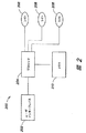
図1を参照すると、本明細書に記述する本発明の一実施態様において、環境100は、1つまたは複数のライトシステム102を含む。本明細書においては、「ライトシステム」は、文脈が適切である範囲において、LEDシステム、ならびにフィラメントランプ、火焔などのパイロルミネセンス光源、ガスマントルなどのキャンドルルミネセンス光源、およびカーボンアーク放射光源を含む白熱光源、ならびにガス放電、蛍光光源、リン光源、レーザ、エレクトロルミネセンスランプのようなエレクトロルミネッセンス光源、発光ダイオード、および電気的飽和を使用するカソードルミネセンス光源を含むフォトルミネッセンス光源、ならびにガルバノルミネセンス光源、結晶ルミネセンス光源、キネルミネセンス光源(kine luminescent source)、熱ルミネセンス光源、摩擦ルミネセンス光源(triboluminescent source)、音ルミネセンス光源、および放射線ルミネセンス光源を含む種々のルミネセンス光源、を含むすべてのライトシステムを含むものである。ライトシステム102には、原色などのカラーを生成することのできる発光ポリマー(luminescent polymer)も含まれる。好ましい一実施態様において、ライトシステム102は、LED式ライトシステムである。また、好ましい一実施態様においては、ライトシステム102は、2つの光の色を混合することが可能であり、この光の色としては、赤、緑、青、白、コハク、またはその他の光の色がある。一実施例として、この光の色は、白色光の異なる色、すなわち異なる色温度の白色光とすることができる。
Referring to FIG. 1, in one embodiment of the invention described herein,
本明細書において使用する場合には、「LED」という用語は、電気信号を受け取り、その信号に応答して光の色を生成することのできる任意のシステムを意味する。したがって、用語「LED」は、すべてのタイプの発光ダイオード、発光ポリマー、電流に応答して光を生成する半導体チップ、エレクトロルミネセンスストリップ、およびその他のシステムを含むものと理解すべきである。一実施例においては、「LED」は、個別に制御される複数の半導体チップを有する、単一の発光ダイオードを意味する。用語「LED」はLEDのパッケージタイプを限定しないことも理解すべきである。用語「LED」は、パッケージLED、非パッケージLED、表面実装LED、チップオンボードLEDおよびその他すべての構成のLEDを含む。用語「LED」はまた、リン光体(phosphor)と共にパッケージにするか、またはそれに関連づけたLEDを含み、これらにおいては、リン光体はLEDからのエネルギーを異なる波長に変換することができる。LEDシステムは、照明光源の1つのタイプである。 As used herein, the term “LED” means any system that can receive an electrical signal and generate a color of light in response to the signal. Thus, the term “LED” should be understood to include all types of light emitting diodes, light emitting polymers, semiconductor chips that generate light in response to electrical current, electroluminescent strips, and other systems. In one embodiment, “LED” means a single light emitting diode having a plurality of individually controlled semiconductor chips. It should also be understood that the term “LED” does not limit the package type of the LED. The term “LED” includes packaged LEDs, non-packaged LEDs, surface mount LEDs, chip on board LEDs and all other configurations of LEDs. The term “LED” also includes LEDs that are packaged with or associated with a phosphor, in which the phosphor can convert energy from the LED to a different wavelength. An LED system is one type of illumination light source.
「照明する」という用語は、照明光源によってある放射周波数が生成されることを意味すると理解すべきである。また用語「光」および「色、カラー(color)」は、文脈が適当な場合には、あるスペクトル内の任意の放射周波数を意味すると理解すべきである。すなわち、本明細書で用いる場合には、「光」の「色」とは、白色光を含む、可視スペクトルの周波数または周波数の組み合わせのみならず、赤外および紫外域スペクトル、およびその他の電磁スペクトルの領域における周波数を包含するものと理解すべきである。 The term “illuminate” should be understood to mean that a certain radiation frequency is generated by the illumination source. Also, the terms “light” and “color” should be understood to mean any radiation frequency within a spectrum where the context is appropriate. That is, as used herein, “color” of “light” includes not only the frequency or combination of frequencies of the visible spectrum, including white light, but also the infrared and ultraviolet spectrum, and other electromagnetic spectra. It should be understood as encompassing frequencies in the region.
図2は、ライティングシステム200の一実施態様を示すブロック図である。プロセッサ204は、いくつかのライト208と関連づけられている。プロセッサは、ライト208に制御信号を送る。このようなシステムは、任意選択として、プロセッサとライト208の間に、1つまたは複数のコントローラ、トランジスタなどの、1つまたは複数の中間構成要素を有してもよい。
FIG. 2 is a block diagram illustrating one embodiment of a
本明細書で用いる場合には、プロセッサの用語は、電子信号を処理する任意のシステムを意味することができる。プロセッサとしては、マイクロプロセッサ、マイクロコントローラ、プログラマブルディジタルシグナルプロセッサ、その他のプログラマブルデバイス、コントローラ、アドレス指定可能コントローラ、マイクロプロセッサ、マイクロコントローラ、アドレス指定可能マイクロプロセッサ、コンピュータ、プログラマブルプロセッサ、プログラマブルコントローラ、専用プロセッサ、専用コントローラ、集積回路、制御回路またはその他のプロセッサがある。プロセッサには、同時に、またはその代わりに、特定用途向け集積回路(ASIC)、プログラマブルゲートアレイ、プログラマブルアレイロジック、プログラマブルロジックデバイス、ディジタルシグナルプロセッサ、アナログ・ディジタルコンバータ、ディジタル・アナログコンバータ、または電子信号を処理するように構成可能なその他のデバイスを含めることができる。 As used herein, the term processor can refer to any system that processes electronic signals. Processors include microprocessors, microcontrollers, programmable digital signal processors, other programmable devices, controllers, addressable controllers, microprocessors, microcontrollers, addressable microprocessors, computers, programmable processors, programmable controllers, dedicated processors, There are dedicated controllers, integrated circuits, control circuits or other processors. The processor may include an application specific integrated circuit (ASIC), programmable gate array, programmable array logic, programmable logic device, digital signal processor, analog to digital converter, digital to analog converter, or electronic signal at the same time or instead. Other devices that can be configured to process can be included.
さらに、プロセッサには、レジスタ、キャパシタ、インダクタ、トランジスタ、オペレーショナルアンプ、その他を含む、受動または能動アナログコンポーネントなどのディスクリート回路、ならびにロジックコンポーネント、シフトレジスタ、ラッチ、またはディジタル機能を実現するための、その他任意の個別パッケージチップもしくはその他のコンポーネントが含まれる。上記の回路およびコンポーネントの、任意の組合せは、チップとして、チップセットとして、またはダイ(die)として別個にパッケージされていても、いなくても、本明細書に記述するプロセッサとしての使用に対して適宜に適合させることができる。またプロセッサの用語は、パーソナルコンピュータ、ネットワークサーバ、または自律的に動作するか、または本明細書に記載するような電子信号を処理するための命令に応答して動作する、その他のシステムにも適用されることが理解されるであろう。プロセッサに、上記のようなマイクロプロセッサまたはマイクロコントローラのようなプログラマブルデバイスが含まれる場合には、このプロセッサには、さらに、プログラマブルデバイスの動作を制御するコンピュータ実行可能なコードが含まれる。一実施例においては、プロセッサ204は、マイクロチップPICプロセッサ12C672(Microchip PIC processor 12C672)であり、ライト208は、赤色LED、緑色LEDおよび青色LEDなどのLEDである。
In addition, the processor includes discrete circuits, such as passive or active analog components, including resistors, capacitors, inductors, transistors, operational amplifiers, etc., as well as others for implementing logic components, shift registers, latches, or digital functions. Any individual package chip or other component is included. Any combination of the circuits and components described above may be used as a processor, as described herein, whether or not packaged separately as a chip, as a chipset, or as a die. Can be adapted accordingly. The term processor also applies to personal computers, network servers, or other systems that operate autonomously or in response to instructions for processing electronic signals as described herein. It will be understood that If the processor includes a programmable device such as a microprocessor or microcontroller as described above, the processor further includes computer-executable code that controls the operation of the programmable device. In one embodiment, the
プロセッサ204には、任意選択として、その他の様々なコンポーネントおよび制御要素(図示せず)、例えばパルス幅変調器、パルス振幅変調器、パルス変位変調器、レジスタラダー、電流源、電圧電源、電圧ラダー、スイッチ、トランジスタ、電圧コントローラ、またはその他のコントローラなどを含むか、あるいはそれらと関連して使用することができる。これらの制御要素およびプロセッサ204は、ライト208を通る、電流、電圧および/または電力を制御することができる。
The
一実施例において、異なるスペクトル出力を有する、いくつかのLEDをライト208として使用することができる。これらのカラーのそれぞれは、個別の制御チャネルによってドライブすることができる。プロセッサ204およびコントローラは、1つのデバイスに組み込むことができる。このデバイスは、一連のいくつかのLEDをドライブする機能に電力供給するか、または1つまたは少数のLEDを直接的にサポートできるだけにすることもできる。プロセッサ204およびコントローラは別個のデバイスとすることもできる。これらのLEDを独立に制御することによって、ライティング効果を創造するためにカラーミキシングを達成することができる。
In one example, several LEDs with different spectral outputs can be used as the light 208. Each of these colors can be driven by a separate control channel. The
一実施例においては、メモリ210を設けることもできる。メモリ210は、アルゴリズム、テーブル、制御信号に関連する数値を記憶することができる。メモリ210は、プロセッサ204、その他のコンポーネント、およびライト208を制御するためのプログラムを記憶することができる。このメモリ210は、メモリ、読出し専用メモリ、プログラマブルメモリ、プログラマブル読出し専用メモリ、電気消去可能プログラマブル読出しメモリ、ランダムアクセスメモリ、ダイナミックランダムアクセスメモリ、2倍データ転送速度ランダムアクセスメモリ、Rambus(ラムバス)ダイレクトランダムアクセスメモリ、フラッシュメモリ、またはプログラム命令、プログラムデータ、アドレス情報、およびプログラム出力もしくはその他の中間または最終結果を記憶するための、その他任意の揮発性または不揮発性メモリとしてもよい。
In one embodiment, a
プログラムは、例えば、いくつかの異なるカラーライト208を動作させる制御信号をストア(格納)することができる。ユーザインターフェイス202も、任意選択で、プロセッサ204と関連づけてもよい。ユーザインターフェイス202を使用することによって、メモリからプログラムを選択し、メモリからのプログラムを修正し、メモリからのプログラムパラメータを修正し、外部信号を選択するか、またはその他のユーザインターフェイスソリューションを提供することができる。カラーミキシングおよびパルス幅変調制御のいくつかの方法が、米国特許第6,016,038号、「マルチカラーLEDライティング方法および装置(Multicolored LED Lighting Method and Apparatus」に開示されており、その全開示を本願に参照として組み入れる。プロセッサ204はまた、アドレス指定可能として、それに対してアドレス指定されたプログラム信号を受け取ることもできる。例えば、プロセッサ204は、複数の類似のプロセッサまたはその他のデバイスのためのデータ要素を含む、データ列(またはライティング制御信号)受け取ることができ、またプロセッサ204は、その列から、それに対してアドレス指定された適当なデータ要素を抽出することができる。一実施態様においては、ユーザインターフェイスには、以下にさらに詳細に記述するような、ライティング制御信号を生成するためのオーサリングツールを含めることができる。
The program can store, for example, control signals that operate several different color lights 208.
LEDの制御においては、大きな進歩があった。LED制御の分野における米国特許としは、整理番号第6,016,038号、第6,150,774号、および第6,166,496号がある。米国特許出願番号第09/716,819号「照明条件を生成および変調するためのシステムおよび方法(Systems and Methods for Generating and Modulating Illumination Conditions)」にも、とりわけ、システムおよび制御について記載されている。これらのすべての文献の、全開示を、本願に参照として組み入れる。本発明のいくつかの実施態様において、ライティングシステムは、環境を照明するのに使用することができる。そのような環境100の1つを図1に示してある。この環境は、その中に装着された、少なくとも1つのライトシステム102を有し、好ましい一実施態様においては、その中に複数のライトシステム102を備えることができる。ライトシステム102は、図2に関係して上述したような、環境100の部分を照明するライト208を備える、制御可能なライトシステム102とすることもできる。
There have been significant advances in LED control. US patents in the field of LED control include Docket Nos. 6,016,038, 6,150,774, and 6,166,496. US patent application Ser. No. 09 / 716,819 “Systems and Methods for Generating and Modulating Illumination Conditions” also describes, among other things, systems and controls. The entire disclosure of all these documents is incorporated herein by reference. In some embodiments of the invention, the lighting system can be used to illuminate the environment. One
一般に、ライトシステム102の装着は、環境100内の観察者が、ライトシステム102によって直接投射された照明を直接見ることができるか、または観察者が、照明がサーフェスから反射した後、またはレンズ、フィルタ、光学系、ハウジング、スクリーン、またはライトシステム102からの照明を、反射、拡散、屈折、回折、またはその他の方法でライトシステム102からの照明に影響を与えるように設計された類似の要素を介して、間接的に見ることができるようにすることができる。
In general, the mounting of the
ライトシステム102は連係して、ライティングまたは照明システムを構成する。ライティングシステムは、制御システム、またはコンピュータなどのその他のユーザインターフェイス202と、当業者には周知の任意の方法で通信してもよく、そのような方法には、それに限定はされないが、有線接続、ケーブル接続、赤外線(IR)接続、ラジオ周波数(RF)接続、その他の任意のタイプの接続、または前記の任意の組合せを含めることができる。
The
様々な制御システムを使用して、以下に述べるように、ライティング制御信号を生成することができる。一実施態様においては、制御はvideo-to-DMXデバイスを経由してライティングシステムに送ってもよく、このデバイスはライティング信号を生成する簡単な方法を提供する。このようなデバイスは、video-inポートおよび通過video-outポートを有してもよい。このデバイスは、ライティング信号ポートも有してもよく、このポートで、DMXまたはその他のプロトコルデータを室内のライトに伝達することができる。このデバイスは、受信したビデオ信号にアルゴリズムを適用し(例えば、平均、所定のセクションまたは時間の平均、最大、最少)、次いでアルゴリズム出力に対応するライティング信号を生成する。例えば、デバイスは1秒の間、信号の平均をとり、青色光に等しい値を結果として得てもよい。次いで、デバイスは青色信号を生成し、それらをライティングシステムに伝達することができる。一実施態様においては、簡単なシステムが同一の平均化信号を室内のすべてのライトに伝達するが、その変形形態は、一部分の信号の平均を、室内の一部分に伝達することである。ビデオ信号に区切りをする多くの方法があり、ライトシステムの様々なセクションにアルゴリズムを適用して、それによって同一のビデオ信号に基づいて異なる入力を提供することもできる。 Various control systems can be used to generate lighting control signals, as described below. In one embodiment, control may be sent to the lighting system via a video-to-DMX device, which provides a simple way to generate a lighting signal. Such a device may have a video-in port and a passing video-out port. The device may also have a lighting signal port through which DMX or other protocol data can be communicated to room lights. The device applies an algorithm to the received video signal (eg, average, average for a given section or time, maximum, minimum) and then generates a lighting signal corresponding to the algorithm output. For example, the device may average the signal for 1 second and result in a value equal to blue light. The device can then generate blue signals and communicate them to the lighting system. In one embodiment, a simple system transmits the same averaged signal to all lights in the room, but a variation is to transmit the average of a portion of the signal to a portion of the room. There are many ways to break the video signal, and the algorithm can be applied to various sections of the light system, thereby providing different inputs based on the same video signal.
図1を参照すると、環境100は、1つまたは複数のライティングシステム102によってライティングされるサーフェス107を含むことができる。図示した実施例においては、サーフェス107は、それらの上で光を反射することができる壁またはその他の表面を含む。別の実施例においては、このサーフェスは、光を吸収して、場合によっては異なる周波数で再送出するように設計することもできる。例えば、サーフェス107は、リンをコーティングしたスクリーンとしてもよく、この場合には、特定のカラーの照明をスクリーン上に投射すると、スクリーンは照明のカラーを変換して、環境100内の観察者に異なるカラーの照明を提供することもできる。例えば、投射された照明は、最初は青、紫、または紫外領域であるのに対して、送出光は主として白とすることもできる。実施例においては、サーフェス107には、ライティングシステムによって照明することのできる、1つまたは複数のカラー、図(figure)、線、設計、絵、写真、テキスチャ、形状またはその他の視覚またはグラフィック要素を含めてもよい。サーフェス上の要素は、テキスチャ、材料、被覆、塗装、染料、顔料、カバー、繊維、またはグラフィックもしくは視覚的な効果を表現するための、その他の方法もしくは機構によって、作成することができる。実施例においては、ライティングシステムからの照明を変更することによって、視覚効果を創出することができる。例えば、サーフェス107上の絵は、フェードするか、もしくは消失するか、あるいはより明白となるか、もしくは再現する可能性がある。したがって、効果は、平坦面上の輝く光によってのみでなく、光とサーフェス上の視覚要素またはグラフィック要素との相互作用によっても、サーフェス107上に創出することができる。
With reference to FIG. 1, the
ある好ましい実施態様においては、ライトシステム102はネットワーク化ライティングシステムであり、この場合には、ライティング制御信号は、アドレス指定された情報のパケットにパッケージされる。次いで、アドレス指定された情報は、ライティングネットワーク内のライティングシステムに伝達される。次いで、ライティングシステムのそれぞれが、特定のライティングシステムにアドレス指定された制御信号に応答することができる。これは、いくつかのライティングシステムを横断するライティング効果を、生成し、かつ連係させるのに非常に有用な配設である。米国特許出願第09/616,214号「ライティング配列をオーサリングするためのシステムおよび方法(Systems and Methods for Authoring Lighting Sequences)」には、システム制御信号を生成するためのシステムおよび方法を記載されており、本願に参照として組み入れる。
In one preferred embodiment, the
ライティングシステム、また本発明の原理によるその他のシステムは、アドレス指定可能なコントローラに関連づけることができる。このアドレス指定可能コントローラは、それ自体のアドレスを「受ける(hear)」まで、ネットワーク情報を「要求する(listen)」ようにすることができる。一旦、システムアドレスが特定されると、システムは、アドレスに割り当てられているデータパケット内の情報を読み取って、それに応答することができる。例えば、ライティングシステムに、アドレス指定可能コントローラを含めることができる。このアドレス指定可能コントローラには、また変更可能なアドレスを含めて、ユーザがシステムのアドレスを設定するようにしもよい。ライティングシステムは、ネットワーク情報が伝達されるネットワークに接続してもよい。ネットワークを使用して、例えば、複数のライティングシステムなどの多数の制御システムに、情報を伝達することができる。このような配設において、複数のライティングシステムのそれぞれが、2つ以上のライティングシステムに関する情報を受け取ることができる。情報は、ビット列の形態にすることができ、その場合には、第1のアドレス指定ライティングシステムに対する情報に、第2のアドレス指定ライティングシステムに宛てられた情報が続く。そのようなライティングシステムの一例が、米国特許第6,016,038号に記載されており、これを参照として本願に組み入れる。 Lighting systems, and other systems in accordance with the principles of the present invention, can be associated with an addressable controller. This addressable controller can be made to “listen” for network information until it “hears” its own address. Once the system address is identified, the system can read and respond to information in the data packet assigned to the address. For example, the lighting system can include an addressable controller. The addressable controller may also include a system address, including a changeable address. The writing system may be connected to a network through which network information is communicated. The network can be used to communicate information to a number of control systems, such as multiple lighting systems, for example. In such an arrangement, each of the plurality of lighting systems can receive information regarding more than one lighting system. The information can be in the form of a bit string, in which case the information for the first addressed writing system is followed by information addressed to the second addressed writing system. An example of such a lighting system is described in US Pat. No. 6,016,038, which is incorporated herein by reference.
図11を参照すると、本発明の原理によるネットワーク化ライティングシステムの一実施態様において、ネットワーク送信装置1102は、ネットワーク情報をライトシステム102に伝達することができる。そのような実施態様において、ライトシステム102には、入力ポート1104および出力ポート1108を含めることができる。ネットワーク情報は第1のライトシステム102に伝達され、第1のライトシステム102は、それに対してアドレス指定されている情報を読み取り、情報の残り部分を次のライトシステム102に送ることができる。当業者であれば、本発明の原理によるシステムに含まれるその他のネットワークトポロジがあることを理解するであろう。
Referring to FIG. 11, in one embodiment of a networked lighting system according to the principles of the present invention, the
一実施態様においては、ライトシステム102は、実世界環境100に設置される。この実世界環境100は部屋とすることができる。ライティングシステムは、例えば、壁、天井、床または部屋の中の、その他のセクションもしくは対象物、または部屋の特定のサーフェス107をライティングするように配設することもできる。このライティングシステムには、個々のアドレスを備えるいくつかのアドレス指定可能ライトシステム102を含めることができる。照明は、室内の観察者に、直接的または間接的に見えるように投射することができる。すなわち、ライトシステム102のライト208が輝き、それによって、光が反射なしに観察者に投射されるか、または反射、屈折、吸収かつ再放出されるか、または任意の他の方法で観察者に間接的に提示されるようにすることができる。
In one embodiment, the
本発明の一実施態様は、図3のブロック図に示すように、制御信号を生成する方法を記述する。この方法は、画像、または画像の表現、すなわちグラフィック表現302を提供または生成することを含む。グラフィック表現は、図面、写真、人工画像、静止または静止して見える画像などの静止画像とすることができる。この静止画像には、画像がスクリーン上で絶え間なくリフレッシュされているが、コンピュータスクリーンまたはその他のスクリーン上に表示される画像を含めることができる。前記静止画像は、また画像のハードコピーとすることもできる。
One embodiment of the present invention describes a method for generating a control signal, as shown in the block diagram of FIG. The method includes providing or generating an image, or a representation of the image, ie, a
グラフィック表現302を提供するステップには、画像または画像の表現を生成するステップも含めることができる。例えば、グラフィック表現302を生成するためのソフトウエアを実行するのに、プロセッサを使用することができる。ここでも、生成される画像は、静止であるか、または静止して見えるか、あるいは画像は動的でもよい。動画像を生成するのに使用されるソフトウエアの一例としては、マクロメディア社(Macromedia, Incorporated)によるフラッシュ5(Flash 5)コンピュータソフトウエアがある。フラッシュ5は、グラフィック、画像およびアニメーションを生成するために広く普及しているコンピュータプログラムである。画像生成するためのその他の有用な製品としては、アドビイラストレータ(Adobe Illustrator)、アドビフォトショップ(Adobe Photoshop)、およびアドビライブモーション(Adobe LiveMotion)が挙げられる。他にも、多数のプログラムが、静止画像と動画像の両方を生成するのに使用することができる。例えば、マイクロソフト社(Microsoft Corporation)は、ペイント(Paint)というコンピュータプログラムを作っている。このソフトウエアは、スクリーン上にビットマップフォーマットで画像を生成するのに使用される。その他のソフトウエアプログラムを使用して、ビットマップ、ベクトル座標またはその他の技法で画像を生成することができる。また、グラフィックスを3次元またはそれ以上の次元で表現するプログラムも多数ある。例えば、マイクロソフト社のDirectXライブラリは、3次元空間に画像を生成する。前述のすべてのソフトウエアプログラムまたは類似のプログラムの出力は、グラフィック表現302として役立てることができる。
Providing the
いくつかの実施態様においては、グラフィック表現302は、プロセッサ上で実行されるソフトウエアを使用して生成することができるが、グラフィック表現302は、スクリーン上に表示されることはない。一実施態様においては、1つのアルゴリズムが、例えば室内におけるエクスプロージョン(爆発)などの、画像またはその表現を生成することができる。エクスプロージョン機能によって、画像を生成することが可能であり、この画像を、本明細書において述べたように、画像をスクリーン上に表示するか、または表示することなく制御信号310を生成するのに使用することができる。この画像は、スクリーン上に一度も表示されることなく、例えば、ライティングネットワークを介して表示することができる。
In some implementations, the
一実施態様において、画像の生成または表現は、プロセッサ上で実行されるプログラムによって達成することができる。一実施態様においては、画像または、画像の表現を生成することの目的は、空間内で定義される情報を提供することである。例えば、画像の生成は、ライティング効果が部屋を通過する方法を定義することができる。ライティング効果は、例えばエクスプロージョン(爆発)を表すことができる。この表現は、室内の角において明るい白色光を発生させて、この光が、部屋の角からある速度(速度および方向を含む)で遠ざかって移動するとともに、その効果の伝播が続くにつれて光の色を変化させることができる。あるライティング効果の速度を示すベクトル104を示す、環境100の図解を図1に示してある。一実施態様においては、画像生成装置は、関数またはアルゴリズムを生成することができる。この関数またはアルゴリズムは、エクスプロージョン、落雷、ヘッドライト、部屋を通過する列車、部屋を貫通する弾丸、部屋を通過して移動する光、部屋を横切る日の出、またはその他の事象などの事象を表すことができる。この関数またはアルゴリズムは、室内に渦巻く光、室内で跳ねる光のボール、室内で反響する音、またはその他の画像などの画像を表すことができる。この関数またはアルゴリズムは、不規則に生成される効果またはその他の効果も表すことができる。
In one embodiment, the generation or representation of the image can be accomplished by a program running on the processor. In one embodiment, the purpose of generating an image or a representation of an image is to provide information defined in space. For example, image generation can define how the lighting effect passes through the room. The lighting effect can represent, for example, an explosion. This representation produces bright white light at the corners of the room, which moves away from the corners of the room at a certain speed (including speed and direction), and the color of the light as the effect continues to propagate. Can be changed. An illustration of the
図3を再び参照すると、ライトシステム構成機能304は、本明細書に記述する方法およびシステムためのさらなるステップを達成することができる。ライトシステム構成機能は、図1に関係して示したもののような、ライティングシステムのための、システム構成ファイル、構成データまたは構成情報を生成することができる。
Referring back to FIG. 3, the light
このライトシステム構成機能は、ライトシステム102、サウンドシステムまたはその他のシステムと、環境100内の1つまたは複数の位置で表すか、またはそれと関係づけることができる。例えば、LEDライトシステム102を、部屋の中の位置と関係づけることができる。一実施態様においては、ライティングされたサーフェス107の場所を、構成ファイルに含めるために決定することができる。ライティングされたサーフェスの位置を、ライトシステム102と関連づけることもできる。いくつかの実施態様においては、ライティングされたサーフェス107を所望のパラメータとしてもよいが、一方でそのサーフェスを照明する光を生成するライトシステム102も重要である。ライティング制御信号は、サーフェスがライトシステム102によってライティングされるようにスケジュールされているときに、ライトシステム102に伝達することができる。例えば、生成された画像が、部屋の特定のセクションの、色相、彩度または輝度を変化させるときに、制御信号をライトシステムに伝達することができる。この状況において、制御信号を使用して、ライティングシステムを制御し、それによってライティングされたサーフェス107が適当な時刻に照明されるようにすることができる。ライティングされたサーフェス107は、壁上に位置することができるが、光をサーフェス107に投射するように設計された、ライトシステム102は、天井に設置することもできる。構成情報は、サーフェス107がライティングされるときに、ライトシステム102を開始して起動または変化させるように配設することもできる。
This light system configuration function can be represented or associated with the
なお図3を参照すると、グラフィック表現302、およびライトシステム構成機能304からの構成情報は、変換モジュール308に配送することが可能であり、この変換モジュールは、構成機能からの位置情報をグラフィック表現からの情報と関連付けて、この情報を、ライトシステム102用の制御信号などの制御信号に変換する。次いで、変換モジュールは、制御信号をライトシステム102などへ、伝達することができる。いくつかの実施態様においては、変換モジュールは、グラフィック表現における位置を、その環境に対して構成ファイルに記憶されている(以下に記述)、環境内のライトシステム102の位置にマッピングする。このマッピングは、グラフィック表現内のピクセルまたはピクセル群の、環境100内のライトシステム102またはライトシステム102の群に対する、1対1のマッピングとすることができる。これは、グラフィック表現内のピクセルの、サーフェス107、ポリゴン、またはライトシステム102によってライティングされる環境内の対象物に対するマッピングとすることもできる。またこれは、ベクトル座標情報、波動関数、またはアルゴリズムのライトシステム102の位置に対するマッピングとすることもできる。多数の異なるマッピング関係が考えつくことができるが、これらは本明細書の範囲に含まれるものである。
Referring to FIG. 3, the
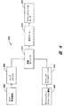
図4を参照すると、制御信号を生成するための方法およびシステムの、別の実施例のブロック図を示してある。ライト管理機能402は、ライトシステム102を環境内の位置、ライトシステムによってライティングされるサーフェス、その他に対してマッピングする、マップファイル404を生成するのに使用する。ライト管理機能は、位置、明暗度、カラー、照明特性、場所、およびライティングシステムのタイプの少なくとも1つを記憶する、複数のライトシステム用の構成ファイルを生成してもよい。アニメーション機能408は、アニメーション効果用の一連のグラフィックスファイル410を生成する。変換モジュール412は、ライトシステム102用のマップファイル404内の情報を、グラフィックスファイル内のグラフィック情報に関係づける。例えば、グラフィックスファイル内のカラー情報は、ライトシステム用のカラー制御信号に変換して、類似のカラーを生成するのに使用することができる。グラフィックスファイル用のピクセル情報は、ライトシステムのアドレス情報に変換することができ、このライトシステムが問題のピクセルに応答することになる。実施形態においては、変換モジュール412は、ライティングシステム用の構成ファイルの内容と問題のアニメーション機能に適当な変換アルゴリズムとに基づいて、特定のグラフィックスファイル情報を、特定のライティング制御情報に変換するための、ルックアップテーブルを含む。変換された情報は、プレイバックツール414に送ることができ、このツールがアニメーションを実行して、制御信号418を環境内のライトシステム102に送り出す。
Referring to FIG. 4, a block diagram of another embodiment of a method and system for generating control signals is shown. The
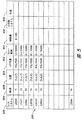
図5を参照すると、ライトシステム102またはその他のシステムのために記憶することのできる構成情報のいくつかの要素を示す、構成ファイル500の一実施態様を示してある。このように、構成ファイル500は、各ライトシステム102の識別子502とともに、その環境100のための、所望の座標系またはマッピングシステム(これは、(x,y,z)座標、極座標、(x,y)座標、その他でよい)におけるそのライトシステムの位置508を記憶することができる。位置508およびその他の情報は、時間依存であってもよく、これによって構成ファイル500は、時間の要素504を含むことができる。構成ファイル500はまた、ライトシステム102でライティングされる位置510についての情報も記憶することができる。その情報は、1組の座標で構成するか、あるいは、それは識別されたサーフェス、ポリゴン、対象物、または環境内のその他の項目とすることができる。構成ファイル500はまた、ライトシステム102の使用に対する利用可能な自由度に関する情報、例えばカラー範囲512内の利用可能なカラー、明暗度(intensity)範囲514における利用可能な明暗度、またはその他を記憶することもできる。構成ファイル500には、本明細書において開示される制御システムによって制御される、環境内のその他のシステムについての情報518、環境内のサーフェス107の特性に関する情報、位置520、その他も含めることができる。すなわち、構成ファイル500は、1組のライトシステム102を、環境100内でそれらが生成することのできる条件に、マッピングすることができる。
Referring to FIG. 5, one embodiment of a
一実施態様においては、構成ファイル500のような構成情報は、プロセッサ上で実行されるプログラムを使用して生成することができる。図6を参照すると、このプログラムは、グラフィックユーザインターフェイスを用いて、コンピュータ600上で実行することができ、この場合には、環境602の表現を表示して、ライトシステム102、ライティングされたサーフェス107またはその他の要素をグラフィックフォーマットで示すことができる。このインターフェイスには、例えば、部屋の表現602を含めることができる。次いで、ライト、ライティングされたサーフェスまたはその他のシステムの表現を、インターフェイス612に提示して、そのシステムに場所を割り当てることができる。一実施態様においては、位置座標または位置マップが、ライトシステムのようなシステムを表すことができる。位置マップは、例えば、ライティングされたサーフェスの表現用にも生成することができる。図6は、ライトシステム102を備える部屋を示す。
In one embodiment, configuration information, such as
表現602は、効果を生成するのを簡単化するためにも使用することができる。例えば、1組の記憶された効果を、アイコン610によってスクリーン上に表すことができる。エクスプロージョンアイコンは、カーソルまたはマウスを用いて選択することができ、これらはユーザに、座標系におけるエクスプロージョンに対する開始点および終了点の上をクリックするように促すことができる。表現内のベクトルを配置することによって、ユーザは、部屋602の上方角においてエクスプロージョンを開始し、光および/または音の波を、環境内で伝播させることができる。ライトシステム102のすべてを、構成ファイル500内に特定されるとおりの所定の位置に配置して、ライトシステムおよび/またはサウンドシステムのような別のシステムによって部屋の中で、エクスプロージョンの表現を再生することができる。
使用においては、本明細書において使用するような制御システムは、ユーザまたはプログラマーに、コンピュータ600のユーザに提供されている情報に応答するか、またはそれと調和させて、ライトシステム102からの情報を提供するのに使用することができる。これを提供する方法の一例は、コンピュータ600上でコンピュータアニメーションを生成しているユーザと関係する例である。ライトシステム102は、コンピュータ600上の表示612に応答して1つまたは複数の光効果を生成するのに使用することができる。このライティング効果、または照明効果は、カラー変更効果、ストロボ効果、フラッシング効果、連係ライティング効果、ビデオやオーディオなどの他のメディアと連係させたライティング効果、カラーの色相、彩度、または明暗度が時間とともに変化するカラーウォッシュ、周囲カラーの生成、カラーフェージング、カラーチェーシングレインボウなどの動きをシミュレートする効果、部屋を横断するフレアストリーキング、日の出、エクスプロージョンからのプルーム(plume)、その他の移動効果、およびその他の多数の効果を含む、広範囲な効果を生成することができる。生成することのできる効果は、無限に近い。光とカラーが連続的にユーザを包囲し、空間内の照明またはカラーを制御または変更することによって、情緒を変化させ、雰囲気を創出し、材質または対象物を強調し、またはその他の快適効果および/または有用な効果を創出することができる。コンピュータ600のユーザは、ディスプレイ612上で効果を修正しながら、その効果を観察することができ、それによってフィードバックループが可能となり、ユーザは効果を簡便に修正を行うことができる。
In use, a control system, as used herein, provides information from the
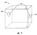
図7は、所与のライトシステム102からの光を、サーフェス上に表示する方法を示す。ライトシステム102、サウンドシステム、またはその他のシステムを、サーフェス上に投射することができる。ライトシステム102の場合には、これは、ライトシステム102によって照明される領域702である。ライトシステム102、またはその他のシステムは、移動が可能であり、それによって領域107も移動する。サウンドシステムの場合には、これは、ユーザが望む、音が発生してくる領域とすることができる。
FIG. 7 illustrates a method for displaying light from a given
一実施態様においては、画像または表現を生成するために生成される情報は、ライトシステム102または複数のライトシステム102に伝達することができる。この情報は、構成ファイルに生成されるとおりに、ライティングシステムに送ることができる。例えば、画像は、部屋の右上方角で開始されるエクスプロージョンを表し、このエクスプロージョンを部屋中に伝播させることができる。この画像が計算された空間を通過して伝播するときに、対応する空間内のライティングシステムに制御信号を伝達することができる。この通信信号によって、ライティングシステムが投射するライティング空間中を画像が通過するときに、ライティングシステムに、所定の色相、彩度および明暗度の光を生成させることができる。本発明の一実施態様では、ライティングシステムを介して画像を投射する。この画像は、コンピュータスクリーンまたはその他のスクリーンもしくは投射装置を介して投射することもできる。一実施態様においては、スクリーンを使用して、ライティングシステム上で画像を再生する前、またはその間に、その画像を可視化することができる。一実施態様においては、サウンドまたはその他の効果を、ライティング効果と関係づけることができる。例えば、空間中を伝播する光波の明暗ピークを、音波より若干前に進ませてもよい。その結果として、光波が部屋を通過して、それに音波が続く。光波は、ライティングシステム上で再生が可能であり、音波はサウンドシステム上で再生が可能である。この連係は、部屋を通過するように見える効果を創出するか、またはこの効果が、その他の様々な効果を創出することができる。
In one embodiment, information generated to generate an image or representation can be communicated to the
図6を参照すると、コンピュータ600のディスプレイスクリーン612上に3次元で表された仮想環境中を、効果が伝播させることができる。一実施態様においては、この効果は、空間中を時間とともに移動するベクトルまたは面としてモデル化することができる。したがって、実世界環境における効果の発生する面上に位置する、すべてのライトシステム102を制御することによって、この効果面がライトシステム面を通過して伝播するときに、ある種の照明を生成することができる。これは、ディスプレイスクリーンの仮想環境においてモデル化することが可能であり、開発者は、時間とともに変化する一連の位置を通過する面をドラグすることができる。例えば、効果面618を、仮想環境中をベクトル608とともに移動させることができる。効果面618がポリゴン614に達するとき、ポリゴンをカラーパレット604から選択されるカラーでハイライトすることができる。そうすると、ポリゴンに対応する実世界対象物に配置されるライトシステム102を、実世界環境において、同じカラーで光らせることができる。もちろんのこと、ポリゴンは、任意の対象物、面、サーフェス、壁、またはその他の上にある任意の構成のライトシステムとすることができ、創出が可能な3D効果の範囲は無限である。
Referring to FIG. 6, the effect can be propagated in a virtual environment represented in three dimensions on the
一実施態様においては、イメージ情報は、中央コントローラから通信することができる。この情報は、ライティングシステムがこの情報に応答する前に、変更することができる。例えば、画像情報を、位置マップ内にある位置に宛てることができる。ある位置マップに宛てられた情報のすべてを、その情報をライティングシステムに送る前に収集することができる。これは、画像がリフレッシュをする毎に、または画像のこのセクションがリフレッシュする毎に、またはその他の時に達成される。一実施態様においては、収集された情報に対してアルゴリズムが実行される。このアルゴリズムは、その情報を平均化し、最大情報を計算して選択し、最小情報を計算して選択し、第1の四分位点を計算して選択し、第3の四分位点を計算して選択し、最も使用された情報を計算して選択し、その情報の積分を計算して選択するか、またはその情報について別の計算を実行する。このステップを完了すると、受け取った情報に応答して、ライティングシステムの効果を一様化することができる。例えば、1リフレッシュサイクルの情報は、マップ内の情報を数回、変更することが可能であり、その効果は、投射された光が、所与のリフレッシュサイクルにおいて1つの値をとるときに、最もよく見ることができる。 In one embodiment, the image information can be communicated from a central controller. This information can be changed before the writing system responds to this information. For example, the image information can be addressed to a position in the position map. All of the information addressed to a location map can be collected before sending the information to the lighting system. This is accomplished every time the image refreshes, every time this section of the image refreshes, or at other times. In one embodiment, an algorithm is executed on the collected information. The algorithm averages the information, calculates and selects the maximum information, calculates and selects the minimum information, calculates and selects the first quartile, and selects the third quartile. Calculate and select, calculate and select the most used information, calculate and select an integral of that information, or perform another calculation on that information. Completing this step can equalize the effects of the lighting system in response to the received information. For example, information in one refresh cycle can change the information in the map several times, and the effect is best when the projected light takes one value in a given refresh cycle. I can see it well.
一実施態様において、ライティングシステムに伝達された情報は、ライティングシステムがその情報に応答する前に、変更することができる。情報フォーマットは、例えば、通信に先立って変化する可能性がある。情報は、コンピュータからUSBポートまたはその他の通信ポートを介して、伝達が可能であり、また、情報のフォーマットは、情報がライティングシステムに伝達されるときに、DMXなどのライティングプロトコルに変更することができる。一実施態様においては、情報または制御信号は、ライティングシステムまたはその他のシステムに、コンピュータ、携帯コンピュータ、ノートブックコンピュータ、パーソナルディジタルアシスタンツ、またはその他のシステムの通信ポートを介して伝達することが可能である。情報または制御信号はまた、電子的またはその他の方法で、メモリ中に記憶して、後で取り出すこともできる。カラーキネティクス社が製造、販売するiPlayer(アイプレイヤ)やSmartJack(スマートジャック)システムなどのシステムは、ライティング制御信号を伝達、および/または記憶するのに使用することができる。 In one embodiment, the information communicated to the lighting system can be changed before the lighting system responds to that information. The information format may change prior to communication, for example. Information can be communicated from a computer via a USB port or other communication port, and the format of the information can be changed to a lighting protocol such as DMX when the information is communicated to the lighting system. it can. In one embodiment, information or control signals can be communicated to a lighting system or other system via a computer, portable computer, notebook computer, personal digital assistants, or other system communication port. is there. Information or control signals can also be stored electronically or otherwise in a memory for later retrieval. Systems such as iPlayer and SmartJack systems manufactured and sold by Color Kinetics can be used to communicate and / or store lighting control signals.
一実施態様においては、いくつかのシステムを、位置マップと関連づけることが可能であり、そのいくつかのシステムが、位置マップを共有するか、またはシステムは、それぞれ独立の位置領域に存在する。例えば、第1のライティングシステムからライティングされたサーフェスの位置は、第2のライティングシステムからライティングされたサーフェスと交差する可能性がある。この2つのシステムは、ライティングシステムのいずれかに伝達される情報になお応答することができる。一実施態様においては、2つのライティングシステムの相互作用も、制御することができる。アルゴリズム、関数またはその他の技法を使用して、相互作用空間における、1つまたは複数のライティングシステムのライティング効果を変更することができる。例えば、相互作用空間が、1つのライティングシステムからの非相互作用空間の半分より大きい場合には、このライティングシステムの色相、彩度または輝度を修正して、相互作用領域を補償することができる。これは、相互作用領域または、例えば隣接領域の全体外観を調整するのに使用することができる。 In one embodiment, several systems can be associated with a location map, the several systems share a location map, or the systems are each in an independent location region. For example, the position of the surface illuminated from the first lighting system may intersect the surface illuminated from the second lighting system. The two systems can still respond to information communicated to either of the lighting systems. In one embodiment, the interaction of the two lighting systems can also be controlled. Algorithms, functions or other techniques can be used to modify the lighting effect of one or more lighting systems in the interaction space. For example, if the interaction space is greater than half of the non-interaction space from one lighting system, the hue, saturation or brightness of this lighting system can be modified to compensate for the interaction region. This can be used to adjust the overall appearance of the interaction area or, for example, an adjacent area.
本発明の原理による方法および/またはシステムを使用して生成された制御信号を使用することによって、広範な効果を生成することができる。得たいと思うファイヤ効果またはエクスプロージョン効果が、壁または部屋中を移動するのを想像して頂きたい。それは、迅速に外に移動する白色フラッシュとして部屋の一端から始まり、それに高輝度黄色波が続き、その明暗度は、部屋を通過して移動するときに変化する。本発明の原理によって制御信号を生成するときに、ライティング設計者は、室内の光、および各ライトシステムのライティング効果のタイミングおよび生成について、関心を払う必要がない。それよりも、設計者は、室内のこれらのライトの相対的位置または実際の位置に関心を払う必要がある。設計者は、室内のライティングを配置して、次いで室内のライトを、上記のような、ピクセル情報などのグラフィック情報と関連づけることができる。設計者は、例えばFlash(フラッシュ)5を使用してファイヤまたはエクスプロージョン効果をコンピュータ上でプログラムすることが可能であり、その情報を環境内のライトシステム102に伝達することができる。環境内でのライトの位置は、ライティングされるサーフェス107または領域702と同様に考慮することができる。
A wide range of effects can be generated by using control signals generated using methods and / or systems according to the principles of the present invention. Imagine the fire or explosion effect you want to get moving through a wall or room. It starts at one end of the room as a white flash that moves out quickly, followed by a high intensity yellow wave, whose intensity changes as it moves through the room. When generating the control signals according to the principles of the present invention, the lighting designer need not pay attention to the timing and generation of lighting in the room and the lighting effects of each light system. Instead, the designer needs to pay attention to the relative or actual position of these lights in the room. The designer can place room lighting and then associate the room light with graphic information, such as pixel information, as described above. The designer can program a fire or explosion effect on the computer using, for example, Flash 5 and communicate that information to the
一実施態様において、ライティング効果は、ライティング効果に追加して、それを強化するサウンドと結合することもできる。その一例が、「赤警報(red alert)」列であり、この場合には、「whoop-whoop(ウー・ウー)」サイレン状効果が、このサウンドと調和した部屋全体の脈動赤色と結合される。1つの刺激が他の刺激を強化する。低周波音とフリッカーライトを使用する地震のサウンドと運動は、これらの効果を連係させる別の例である。光と音の移動を使用することによって方向を指示することができる。一実施態様においては、ライトは、2次元または平面図内で表される。これによって、ライトを様々なピクセルと関連づけることのできる、面内のライトを表すことができる。次いで、標準的なコンピュータグラフィックス技法を使用して効果を出すことができる。アニメーションツイーニング(animation tweening)や標準ツールでも、ライティング効果を創出するのに使用することができる。マクロメディアフラッシュ(Macromedia Flash)は、比較的低解像度のグラフィックスと協働して、ウエブ上にアニメーションを創出する。Flash(フラッシュ)は、簡単なベクトルグラフィックスを使用して、簡便にアニメーションを創出する。ベクトル表現は、ワールド・ワイド・ウエブ上にあるようなストリーミングアプリケーションに対して、ネット上でアニメーションを送るのに効率的である。同じ技術を使用して、ピクセル情報またはベクトル情報を、環境100用の座標系内で、ライトシステム102の位置に対応するベクトルまたはピクセルにマッピングすることによって、ライティング命令を取り出すのに使用できるアニメーションを創出することができる。
In one embodiment, the lighting effect can be combined with a sound that adds to and enhances the lighting effect. One example is the “red alert” column, where the “whoop-whoop” siren-like effect is combined with the pulsating red of the entire room in harmony with this sound. . One stimulus enhances the other. Seismic sounds and movements that use low frequency sounds and flicker lights are another example of linking these effects. Direction can be indicated by using light and sound movement. In one embodiment, the lights are represented in two dimensions or plan views. This can represent in-plane lights that can be associated with various pixels. The effect can then be produced using standard computer graphics techniques. Animation tweening and standard tools can also be used to create lighting effects. Macromedia Flash creates animations on the web in collaboration with relatively low resolution graphics. Flash creates simple animation using simple vector graphics. Vector representations are efficient for sending animations over the net to streaming applications such as those on the World Wide Web. Using the same technique, an animation that can be used to retrieve lighting instructions by mapping pixel or vector information into a vector or pixel corresponding to the position of the
例えば、コンピュータ600のアニメーションウインドは、ライトの部屋またはその他の環境を表すことができる。そのウインド内のピクセルは、部屋の中のライトと対応付けるか、または低解像度の平均化画像を、高解像度画像から生成することができる。この方法によって、部屋の中のライトは、対応するピクセルまたはピクセルの近傍がオンになるときに、起動させることができる。LED式ライティング技術は、米国特許第6,016,038号、米国特許第6,150,774号、および米国特許第6,166,496号に記載されており、要求に応じてディジタル制御情報を使用して任意のカラーを創出できるので、ライトは元の画像のカラーを忠実に再生することができる。
For example, the animation window of
本発明の原理によるシステムおよび方法を使用して生成することのできる効果の例としては、それに限定はされないが、エクスプロージョン、カラー、水中効果、渦、カラー変化、火炎、ミサイル、チェース、部屋の回転、形状移動、ティンカーベル状形状、部屋内を移動するライト、およびその他多数が挙げられる。これらの効果のいずれも、周波数、波長、波の幅、ピークツーピーク測度、速度、慣性力、摩擦、スピード、幅、スピン、ベクトル、などのパラメータによって指定することができる。これらのいずれも、サウンドなどの他の効果と結合することができる。 Examples of effects that can be generated using systems and methods according to the principles of the present invention include, but are not limited to, explosions, colors, underwater effects, vortices, color changes, flames, missiles, chase, room Rotation, shape movement, tinker bell shape, lights moving through the room, and many others. Any of these effects can be specified by parameters such as frequency, wavelength, wave width, peak-to-peak measure, speed, inertial force, friction, speed, width, spin, vector, and the like. Any of these can be combined with other effects such as sound.
コンピュータグラフィックスにおいて、アンチエイリアシングとは、エッジが引き延ばされて、かつ解像度が限られている場合に、画像の階段状効果を除去する技法である。この効果は、狭い縞状パターンが示されたときにテレビジョン上で見られる。このエッジは、ラインが水平に近づくにつれて、蟻が這うように見える。類似の方法で、効果の移動中のより円滑な遷移をもたらすように、ライティングを制御することができる。波の幅、振幅、位相または周波数を修正して、それによってより良好な効果をもたらすことができる。 In computer graphics, anti-aliasing is a technique that removes the stepped effect of an image when the edges are stretched and the resolution is limited. This effect is seen on television when a narrow striped pattern is shown. This edge appears to ant crawl as the line approaches horizon. In a similar manner, lighting can be controlled to provide a smoother transition during effect transfer. The wave width, amplitude, phase or frequency can be modified thereby producing a better effect.
例えば、図8を参照すると、概略図800は、単一のライト804を時間の経過で示す円が示されている。このライトを「横移動」させる効果のためには、波がライトを通過するときにライトをパルスさせる、ステップ関数を有するだけでよい。しかしながら、幅についての考えがなければ、効果は見分け難い。この効果は、幅を有するのが好ましい。しかしながら、ライトに対する効果が、ある時間オンにされる単にステップ関数である場合には、粗い遷移に見えるかもしれないが、これはある場合には望ましいが、時間とともに移動する(すなわち、それに関連するなんらかの速度を有する)効果に対しては、これは通常、当てはまらない。
For example, referring to FIG. 8, a schematic diagram 800 shows a circle showing a
図8に示す波802は、変化に対応する形状を有する。本質的に、それは、波802が空間中を伝播するときの、波の視覚的コンボルーションである。したがって、エクスプロージョンによるものなどの波が、空間内の点を通過すると、これらの点の明暗度がゼロから上昇し、かつ色相または彩度における関連する変化を起こすことができ、これは効果の移動により現実的な効果を与える。いずれかの点において、ライトの数および濃度が増加するにつれて、部屋はスクリーンの延長となり、大きなまばらなピクセルを提供する。比較的少数のライトシステム102の場合でも、この効果は、結局は大型スクリーンディスプレイと類似するディスプレイとして作用する。
A
効果は、対応する移動および方向、すなわち速度を有することができる。その他の物理的パラメータを記述して、摩擦、慣性および運動量などの物理的パラメータをもたらすことさえも可能である。それ以上に、効果は、特定の軌道を有することができる。一実施態様においては、各ライトは、ライトの属性を与える表現を有することができる。これは、例えば2次元位置の形態をとることができる。ライトシステム102は、割り当てられた様々な自由度のすべて(例えば、xyz‐rpy)、または任意の組合せを有することができる。ここに列挙した技法は、ライティングに限定はされない。制御信号は、花火製造技術(pyrotechnics)、臭い発生装置、フォグマシン、バブルマシン、移動機構、音響装置、空間を移動する音響効果、またはその他のシステムなどの特殊効果デバイスのような、その他のデバイスを介してその位置に基づいて伝播させることができる。
The effect can have a corresponding movement and direction, ie speed. Other physical parameters can be described to even provide physical parameters such as friction, inertia and momentum. More than that, the effect can have a specific trajectory. In one embodiment, each light can have a representation that gives the attributes of the light. This can take the form of a two-dimensional position, for example. The
本発明の一実施態様は、環境内のライトシステム102の位置を自動的に取り込む方法である。イメージングデバイスを、ライトの位置を取り込む手段として、使用することができる。計算装置に接続されたカメラは、分析のための画像を取り込み、ライトの位置を計算することができる。図9は、この方法を達成するのに使用される一連のステップを示すフロー図900を示す。最初に、ステップ902において、マッピングすべき環境を、周囲光を低減して暗くすることができる。次に、ステップ904において、制御信号を各ライトシステム102に送り、ライトシステム102を交互にオン、オフにするように命令する。同時に、カメラは、ステップ906において、各「オン」時中に画像を取り込むことができる。次に、ステップ908において、画像が分析されて、「オン」ライトシステム102の位置を同定する。ステップ910においては、図心を抽出することができる。特定のライトシステム102がオンのときには、他のライトは存在しないので、画像からフィルタリングして除去すべき他のアーチファクトの問題は少ない。次に、ステップ912において、ライトシステム102の図心位置を記憶し、システムは、ライトシステム102および図心位置のテーブルを生成する。このデータは、図5に関係して示したような、構成ファイルに入れるために使用することができる。要するに、各ライトシステム102は、交互に起動されて、図心測定値が求められる。これは、すべてのライトシステム102に対して行われる。したがって、1つの画像から、面内のライトシステムの位置を(x,y)座標などが得られる。
One embodiment of the present invention is a method for automatically capturing the position of the
3D位置が望ましい場合には、第2の画像を取り込み、別の座標次元におけるライトの位置を3角測量することができる。これはステレオ問題である。人の眼が、両眼から得られる画像間の対応と不一致から奥行きを測定することができるのと同じ方法で、第2のセットの画像を取り込むことで対応を提供することができる。カメラは、第1のカメラに対して既知の位置に重複させるか、または第1のカメラを既知の距離と方向に移動させる。この移動または位置の差によって、2つの画像のベースラインを確定し、これによってライトシステム102に対する第3の座標(例えば、(x,y,z))を導き出すことができる。
If a 3D position is desired, the second image can be captured and the position of the light in another coordinate dimension can be triangulated. This is a stereo problem. Correspondence can be provided by capturing a second set of images in the same way that the human eye can measure depth from the correspondence and mismatch between images obtained from both eyes. The camera overlaps a known position with respect to the first camera or moves the first camera to a known distance and direction. This difference in movement or position can establish a baseline for the two images, thereby deriving a third coordinate (eg, (x, y, z)) for the
本発明の別の実施態様を図10に示してあり、この図は、制御信号を生成するステップを含む、フロー図1000を含む。最初に、ステップ1002において、ユーザは、図6に示したディスプレイ612のようなグラフィックユーザインターフェイスにアクセスすることができる。次に、ステップ1003において、ユーザは、グラフィックプログラム、または同様の機能を使用するなどして、ディスプレイ上に画像を生成するこができる。画像は、部屋、壁、建物、サーフェス、対象物、またはその他などの、環境の表現とすることができ、この中にライトシステム102が配置される。図10と関係して、環境内のライトシステム102の構成は既知であり、テーブルまたは構成ファイル500などに、記憶されていると仮定される。次に、ステップ1004において、ユーザは、効果のメニューなどから効果を選択することができる。一実施態様においては、この効果は、カラーパレットから選択されるカラーとすることができる。このカラーは、白色の色温度とすることもできる。効果は、本明細書に記述するような、別の効果とすることもできる。一実施態様においては、画像の生成1003は、プロセッサ上で実行されるプログラムによって達成することができる。
Another embodiment of the present invention is shown in FIG. 10, which includes a flow diagram 1000 that includes generating control signals. Initially, at
次いで、画像をコンピュータスクリーン上に表示することができる。ステップ1004において、一旦、パレットからカラーが選択されると、ステップ1008において、ユーザは画像の一部分を選択することができる。これは、グラフィックユーザインターフェイス内で、スクリーン上のカーソルを使用することによって達成することができ、その場合には、カーソルを画像の所望の部分に置いて、次いでその部分をマウスで選択する。画像の一部分の選択に続いて、ステップ1010において、その部分からの情報を、ライティング制御信号に変換することができる。これには、ビットストリームを変更すること、または、その情報を他の情報に変換することを伴う。画像を形成した情報は、赤、緑、および青などのいくつかのカラーにセグメント化する(分ける)ことができる。その情報はまた、例えばセグメント化された赤、緑、青信号としてライティングシステムに伝達することもできる。この信号はまた、ステップ1012において、コンポジット信号としてライティグシステムに伝達することもできる。この技法は、ライティングシステムのカラーを変更するのには有用である。例えば、カラーパレットをグラフィックユーザインターフェイス内に提示することが可能であり、そのパレットは数百万の異なるカラーを表すことができる。
The image can then be displayed on a computer screen. In
ユーザは、部屋またはその他の領域において、深い青色にライティングを変更することを望むかもしれない。このタスク(課題)を達成するために、ユーザはマウスを使用してスクリーンからカラーを選択することができ、そうすると、部屋内のライティングが、ユーザが選択したスクリーンの部分のカラーに一致するように変化する。一般に、コンピュータスクリーン上の情報は、赤、緑、青の小さなピクセルで提示される。米国特許第6,016,038号、米国特許第6,150,774号、米国特許第6,166,496号に記載されているようなLEDシステムには、赤、緑および青のライティング要素も含めることができる。スクリーン上の情報から制御信号への変換プロセスは、ライティングシステムが命令を理解するようにするための、フォーマット変更でよい。しかしながら、一実施態様においては、情報または個別のライティング要素のレベルは、ピクセル情報を生成するのに使用される情報と、同じにすることができる。これによって、ライティングシステム内での、ピクセル情報の正確な複製が得られる。 The user may wish to change the lighting to deep blue in the room or other area. To accomplish this task, the user can use the mouse to select a color from the screen so that the lighting in the room matches the color of the portion of the screen selected by the user. Change. In general, information on a computer screen is presented in small pixels of red, green and blue. LED systems such as those described in US Pat. No. 6,016,038, US Pat. No. 6,150,774, US Pat. No. 6,166,496 also have red, green and blue lighting elements. Can be included. The process of converting information on the screen into control signals can be a format change to allow the lighting system to understand the instructions. However, in one embodiment, the level of information or individual lighting elements can be the same as the information used to generate the pixel information. This provides an accurate reproduction of the pixel information within the lighting system.
環境内のライトシステムの位置を同定する技法、環境内での効果(時間および形状に基づく効果を含む)をモデリングする技法、ライトシステム環境を仮想環境にマッピングする技法を含む、本明細書に記述する技法を使用すれば、無限の範囲の環境において、無限の範囲の効果をモデリングすることが可能である。効果は、正方形または長方形のディスプレイ上で創出可能なものだけに限定する必要はない。そうではなく、ライトシステムは、広範囲のライン、ストリング、カーブ、ポリゴン、円錐、円筒、立方体、球、半球、非線形形状、雲、および任意の形状および構成に配置して、次いで、選択された座標次元におけるそれらの位置を取り込む仮想環境内にモデル化することができる。すなわち、ライトシステムは、部屋、建物、家、物体、製品、卸売り店、車両、船舶、航空機、プール、スパ、病院、手術室、またはその他の場所などの、任意の環境の内部または外部に配置することが可能である。 Described herein, including techniques for identifying the location of a light system in the environment, techniques for modeling effects within the environment (including effects based on time and shape), and techniques for mapping the light system environment to a virtual environment Can be used to model an infinite range of effects in an infinite range of environments. The effect need not be limited to what can be created on a square or rectangular display. Rather, the light system is placed in a wide range of lines, strings, curves, polygons, cones, cylinders, cubes, spheres, hemispheres, non-linear shapes, clouds, and any shape and configuration, then selected coordinates You can model in a virtual environment that captures their position in a dimension. That is, the light system is placed inside or outside any environment, such as a room, building, house, object, product, wholesale store, vehicle, ship, aircraft, pool, spa, hospital, operating room, or other location Is possible.
いくつかの実施態様においては、ライトシステムは、コンピュータアプリケーションのコードと関連づけて、それによって、コンピュータアプリケーションコードを修正または生成して、ライトシステムを制御することができる。例えば、オブジェクト指向プログラミング技法を使用して、コンピュータコード中で、対象物に属性を付与して、この属性を、ライトシステムの挙動を支配するのに使用することができる。オブジェクト指向技法は、当該分野において知られており、チモシー・バッド(Timothy Budd)「オブジェクト指向入門(Introduction to Object-Oriented Programming)」などの教科書に記述されており、この全開示を参照として本願に組み入れる。その他のプログラミング技法を使用して、ライティングシステムを、コンピュータアプリケーションと連係して、発光させることもできることを理解すべきであり、オブジェクト指向プログラミングは、当業者であれば、本明細書において記述した方法およびシステムを容易にすることを理解するであろう、種々のプログラミング技法の1つである。 In some implementations, the light system can be associated with the code of the computer application, thereby modifying or generating the computer application code to control the light system. For example, object oriented programming techniques can be used to assign attributes to objects in computer code, and these attributes can be used to govern the behavior of the light system. Object-oriented techniques are known in the art and are described in textbooks such as “Timothy Budd” “Introduction to Object-Oriented Programming”, the entire disclosure of which is incorporated herein by reference. Incorporate. It should be understood that other programming techniques can be used to cause the lighting system to illuminate in conjunction with a computer application, and object-oriented programming can be performed by those skilled in the art using the methods described herein. And one of a variety of programming techniques that will be understood to facilitate the system.
一実施態様においては、開発者は、ライトシステム入力を、コンピュータアプリケーション内の対象物に付与することができる。例えば、開発者は、アプリケーションオブジェクトの、コード構成に追加されるライトシステム102の抽象、またはオブジェクトを有してもよい。オブジェクトは、位置、速度、カラー、明暗度、またはその他の値などの、様々な属性からなる。開発者は、コンピュータアプリケーションのコード内で、オブジェクト内のインスタンスとして、ライト(light)を加えることができる。例えば、オブジェクトは、オブジェクト指向コンピュータアニメーションプログラムやソリッドモデリングプログラムにおいては、方向や速度などの属性を有する、ベクトルとすることができる。ライトシステム102は、コンピュータアプリケーションのオブジェクトのインスタンスとして加えることが可能であり、ライトシステムは、明暗度、色、および様々な効果などの属性を有することができる。すなわち、コンピュータアプリケーションにおいてベクトルのオブジェクトを求める、イベントが発生すると、プログラムを通して実行されるスレッドが、ライトシステムのプロセッサへの入力として働くコードを引き出すことができる。ライトは、正確に、形状、配置、空間位置を表すか、属性または特性(trait)の値を表すか、またはその他の要素またはオブジェクトの指示を提供する。
In one implementation, a developer can provide light system input to objects in a computer application. For example, the developer may have an abstraction of
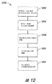
図12を参照すると、フローチャート1200は、連係照明を提供する方法のためのステップを提供する。ステップ1202において、プログラマーは、例えば、オブジェクト指向プログラミング技法を使用して、コンピュータアプリケーション用のオブジェクトをコーディングする。ステップ1204において、プログラミングは、アプリケーションにおける、それぞれのオブジェクトに対してインスタンスを生成する。ステップ1208においては、プログラマーは、アプリケーションの1つまたは複数のオブジェクトに、ライトをインスタンスとして加える。ステップ1210において、プログラマーは、アプリケーションコードを通して実行されるスレッドを準備する。ステップ1212においては、プログラマーは、スレッドを提供して、ライティングシステム入力コードを、ライトをインスタンスとして有するオブジェクトから、引き出す。ステップ1214において、ステップ1212においてスレッドから引き出された入力信号は、ライトシステムに供給され、それによってライティングシステムは、コンピュータアプリケーションから引き出されたコードに応答する。
Referring to FIG. 12, a
コンピュータアプリケーションのコードからライトシステム102への、そのようなオブジェクト指向入力を使用すれば、様々なライティング効果を、実世界環境において、コンピュータアプリケーションの仮想世界オブジェクトと関連づけることができる。例えば、ポリゴンのエクスプロージョンなどの効果のアニメーションにおいて、光効果に、サウンド、フラッシング、移動、信号およびその他の時間効果などの、ポリゴンのエクスプロージョンをアタッチすることができる。さらに、ライトシステム102は、サウンド生成デバイス、運動生成デバイス、フォグマシン、レインマシン、またはそのオブジェクトに関する指示を生成することのできるその他のデバイスを含み、その他の効果デバイスを含むことができる。
Using such object-oriented input from the computer application code to the
図13を参照すると、フロー図1300は、コンピュータスクリーンの仮想環境上の表現と、実環境におけるライトシステム102またはライトシステム102の組との連係照明のステップを示す。いくつかの実施態様においては、ライトシステム102の制御用のプログラムコードは、その制御信号を提供するマシン上で実行される個別のスレッドを有する。ステップ1302において、プログラムはスレッドを起動する。ステップ1304において、仮想ライトのリスト、すなわち仮想環境におけるライトを表すプログラムコードにおけるオブジェクトについて、スレッドをできる限り頻繁に実行する、ステップ1308において、スレッドは3次元計算を実行して、環境の中のどの実世界ライトシステム102が、コンピュータ表現による仮想環境内の、対象物の座標系の基準点として投射されている、実世界における基準点(例えば、選択されたサーフェス107)に近いかを判定する。このようにして、(0,0,0)位置を、実環境における場所であり、かつコンピュータアプリケーションのディスプレイにおけるスクリーン上の点とすることができる。ステップ1310において、コードは、ライトシステム102を含む、実世界環境に仮想環境をマッピングし、それによって、コンピュータスクリーンの外で発生しているイベントと基準点との関係が、コンピュータスクリーン上の仮想対象物およびイベントと基準点との関係と同様になる。
Referring to FIG. 13, a flow diagram 1300 illustrates the steps of coordinated lighting of a virtual environment representation of a computer screen and a
ステップ1312において、本方法のホストは、マッピング用のインターフェイスを提供することができる。このマッピング関数は、関数、例えば、以下と付録Aに示すDirectlight APIに記述した、「project-all-lights」によって行うことができ、この関数は、ドラグやドロップインターフェイスなどの簡単なユーザインターフェイスを使用して実世界ライトをマッピングする。ライトの配置は、ライトが向けられるサーフェスほどは重要でないかもしれない。照明またはライトを環境に反射するのはこのサーフェスである可能性があり、その結果、マッピングプログラムに対して最も重要なのはこのサーフェスである可能性がある。このマッピングプログラムは、ライトシステム位置よりも、これらのサーフェスをマッピングするか、またはライトシステムの位置とサーフェス上のライトの両方をマッピングしてもよい。連係照明用のコードを提供するシステムは、プロセッサ、オペレーティングシステム、および実行のためのファイルを記憶するためのデータベースメモリを含む、プログラミングの可能な任意適切なコンピュータとすることができる。
In
それぞれの実物ライト102は、構成ファイルに記憶された属性を有することができる。構成ファイルの構造の例が、図5に示してある。いくつかの実施態様においては、構成ファイルには、ライト数、各ライトの位置、ライト出力の位置または方向、ライトのガンマ(輝度)、1つまたは複数の属性の指示番号、およびその他種々の属性などの様々なデータを含めることができる。構成ファイル内の座標を変更することによって、実世界ライトを、スクリーン上に表される仮想世界に、それらが仮想世界で発生していることを反映するように、マッピングすることができる。したがって、開発者は、エクスプロージョンのような時間依存効果を創出することができる。次いで、様々なアプリケーション属性にアタッチすることのできる、コード中の効果のライブラリとすることができる。例としては、エクスプロージョン、レインボウ、カラーチェース、フェードインおよびフェードアウト、などが挙げられる。開発者は、これらの効果を、アプリケーションにおける仮想対象物に付与する。例えば、エクスプロージョンが終了したとき、構成ファイルないのライトに関連する対象物の消去を反映して、ライトはディスプレイ内で消える。
Each
構成ファイルを簡単化するために、様々な技法を使用することができる。いくつかの実施態様においては、順番に配列した半球カメラを、換算係数を含むベースラインとして使用して、ライトを3角測量して、ライトのある位置を計測する必要なく構成ファイルを自動的に生成することができる。いくつかの実施態様においては、構成ファイルは、タイプインするか、または光源を環境の表現の上にドラグしたりドロップするのに使用可能な、グラフィックユーザインターフェイスに入れることができる。開発者は、実環境内に現実に配置された備品に一致する構成ファイルを生成することができる。例えば、一旦、ライティング要素をドラグして、環境内にドロップすると、プログラムは、プログラム内の仮想ライトと、環境内の実物ライトを関連づけることができる。ライティングの構成を支援する、ライトオーサリングプログラムの例が、米国特許出願番号第09/616,214号、「ライティング順序のオーサリングのためのシステムおよび方法(Systems and Methods for Authoring Lighting Sequences)」に記載されている。カラーキネティクス社(Color Kinetics Inc.)は、「ColorPlay」という名称の、好適なオーサリングおよび構成プログラムも提供している。 Various techniques can be used to simplify the configuration file. In some embodiments, an ordered hemispherical camera is used as a baseline with a conversion factor to triangulate the light and automatically generate the configuration file without having to measure the location of the light. Can be generated. In some implementations, the configuration file can be typed in or placed into a graphic user interface that can be used to drag or drop a light source over the representation of the environment. Developers can generate configuration files that match equipment that is actually placed in the real environment. For example, once a lighting element is dragged and dropped into the environment, the program can associate a virtual light in the program with a real light in the environment. An example of a light authoring program that supports the construction of lighting is described in US patent application Ser. No. 09 / 616,214, “Systems and Methods for Authoring Lighting Sequences”. ing. Color Kinetics Inc. also provides a suitable authoring and configuration program named “ColorPlay”.
このコードの実装に関するさらなる詳細は、付録Aとして本明細書に添付した、Directlight API説明書に記述されている。Directlight APIは、プログラマーがライティング効果をプログラム中に組み入れることを可能にする、プログラマーインターフェイスである。Directlight APIは、付録Aおよび参照として本願に組み入れる開示に添付してある。オブジェクト指向プログラミングは、ライティング効果を組み込むために使用するプログラミング技法の一例にすぎない。ライティング効果は、任意のプログラミング言語またはプログラミング方法に組み入れることができる。オブジェクト指向プログラミングにおいては、プログラマーは、3D空間をシミュレートすることが多い。上記の例においては、期待される光を生成するか、または光が付与される対象物の位置を指示するのに、ライトを使用した。ライトを使用する方法には、他にも多くの方法がある。ライトシステム中のライトは、コンピュータアプリケーションにおいて(ゲームなどの)イベントを指示したり、オブジェクトのレベルまたは属性を指示するなど、様々な目的で使用することができる。 Further details regarding the implementation of this code can be found in the Directlight API documentation attached hereto as Appendix A. The Directlight API is a programmer interface that allows programmers to incorporate lighting effects into their programs. The Directlight API is attached to Appendix A and the disclosure incorporated herein by reference. Object-oriented programming is just one example of a programming technique used to incorporate lighting effects. Writing effects can be incorporated into any programming language or programming method. In object-oriented programming, programmers often simulate 3D space. In the above example, a light was used to generate the expected light or to indicate the position of the object to which the light was applied. There are many other ways to use lights. Lights in a light system can be used for various purposes, such as indicating events (such as games) in a computer application, or indicating the level or attribute of an object.
コンピュータアプリケーションのシミュレーションタイプは、3D表現されて、属性とイベントを含むオブジェクトを有することが多い。プログラマーは、実世界環境のシミュレーションなどの、シミュレーションのためにアプリケーション中にイベントをコーディングすることができる。プログラマーは、シミュレーション中で属性またはオブジェクトをコーディングすることができる。すなわち、プログラムは、エクスプロージョン、弾丸、価格、製品特徴、健康、他の人々、光パターン、その他などのイベントおよび属性を追跡することができる。次いで、そのコードは、仮想世界から実世界へのマッピングを行うことができる。いくつかの実施態様においては、任意選択のステップにおいて、システムは、仮想世界に、センサや入力デバイスによるなどの、実世界データを追加することができる。次いで、システムは、実世界および仮想世界のオブジェクトを互いに連係させて制御することができる。また、ライトシステムをインジケータとして使用することによって、ライトシステムを介して、実世界環境の人を支援する情報を提供することができる。 Computer application simulation types are often expressed in 3D and have objects including attributes and events. A programmer can code events in an application for simulation, such as simulation of a real world environment. The programmer can code attributes or objects in the simulation. That is, the program can track events and attributes such as explosions, bullets, prices, product features, health, other people, light patterns, etc. The code can then perform a mapping from the virtual world to the real world. In some implementations, in an optional step, the system can add real world data, such as by sensors or input devices, to the virtual world. The system can then control real world and virtual world objects in conjunction with each other. In addition, by using the light system as an indicator, it is possible to provide information for supporting a person in the real world environment through the light system.
建築ビジュアライゼーション、機械工学モデル、およびその他のソリッドモデリング環境は、本明細書の実施態様の範囲に含まれる。このような仮想環境において、ライティングは、仮想環境と、ソリッドモデル実世界ビジュアライゼーション環境との両方に関係することが多い。したがってユーザは、実世界ソリッドモデルを照明する、ライトシステム102を配置かつ制御して、仮想世界モデリング環境において創出される照明条件に応じて、実世界ソリッドモデルを照明することができる。ライトを有する部屋における縮尺物理モデルは、以前には分かっていなかった、ライトと様々な建物サーフェスとの相互作用を検出するために、一日または一年を通じてのライティング、あるいは例えば、異なる季節の間のライティングについてモデリングすることができる。別の例としては、都市または都市の一部のレプリカを、上述のようなライティングシステムを備える、部屋の中に構築することがある。
Architectural visualization, mechanical engineering models, and other solid modeling environments are within the scope of embodiments herein. In such a virtual environment, lighting is often related to both the virtual environment and the solid model real-world visualization environment. Thus, the user can place and control the
次いで、このモデルについて、時間経過によるカラー変化、陰影表示、またはその他のライティング効果について分析することができる。一実施態様においては、この技法は、景観設計に使用することができる。一実施態様においては、このライティングシステムを、部屋、建物、またはその他の建築物をモデリングするのに使用する。例えば、インテリアデザイナは、部屋、または布地、または部屋の中の対象物のカラーを、一日、一年もしくは季節の様々な時刻を表すカラーで投影することを望むかもしれない。一実施態様においては、ライティングシステムを使用することによって、店舗内のペイント売り場の近傍で使用して、様々な条件下でのペイント色の可視化のための、ペイントチップ(paint chip)上のライティング条件のシミュレーションが可能になる。これらのタイプの実世界モデリングアプリケーションは、年間のある時期において日光をドライバの眼に向けて反射する反射の多い建物などの、潜在的な設計欠陥の検出を可能にする。さらに、これらの3次元ビジュアライゼーションによって、さらに複雑なコンピュータモデリングによるよりも、設計の美しさに対する人によるより迅速な認識が可能となる。 The model can then be analyzed for color changes over time, shading, or other lighting effects. In one embodiment, this technique can be used for landscape design. In one embodiment, the lighting system is used to model a room, building, or other building. For example, an interior designer may want to project the color of a room, or fabric, or an object in the room with colors that represent various times of the day, year, or season. In one embodiment, by using a lighting system, lighting conditions on a paint chip for visualization of paint color under various conditions, used in the vicinity of a paint department in a store. Simulation becomes possible. These types of real-world modeling applications allow the detection of potential design defects such as highly reflective buildings that reflect sunlight toward the driver's eyes at some time of the year. In addition, these three-dimensional visualizations allow for more rapid human perception of design aesthetics than by more complex computer modeling.
ソリッドモデリングプログラムは、仮想ライトを備えることができる。仮想環境において、モデルをライティングするとともに、同時に実世界モデルを同様にライティングすることができる。例えば、モデルの環境条件をモデル化して、仮想環境の外部の実世界モデリング環境においてそれらの環境条件を再生することができる。例えば、家屋またはその他の建物をモデリングして、任意の日射環境におけるそれの見え方を示すことができる。愛好家は、模型列車セット(例えば、実際の列車の絵に基づいて)のライティングをモデリングして、そのライティングを、模型列車が存在する部屋の照明に変換することができる。したがって、模型列車は、実際の列車の物理的な表現であるだけでなく、列車が特定の時間に出現したように見せることもできる。土木工学プロジェクトも、模型として組み立てて、次いで本発明の原理によるライティングシステムを使用して、一日周期のライティング条件をシミュレートすることができる。 The solid modeling program can comprise a virtual light. In a virtual environment, you can write a model and simultaneously write a real world model as well. For example, the environmental conditions of the model can be modeled and reproduced in a real world modeling environment outside the virtual environment. For example, a house or other building can be modeled to show how it looks in any solar radiation environment. The enthusiast can model the lighting of a model train set (eg, based on a picture of an actual train) and convert the lighting to the lighting of the room where the model train is located. Thus, a model train is not only a physical representation of an actual train, but can also appear as if the train appeared at a particular time. Civil engineering projects can also be assembled as models and then simulated lighting conditions for a one-day cycle using a lighting system according to the principles of the present invention.
このシミュレーションは、ライティング条件、陰影、カラー効果、またはその他の効果を生成するのに使用することができる。この技法はまた、映画/劇場(Film/Theatrical)モデルにおいて使用するか、映画制作において特殊効果を生成するのに使用することができる。そのようなシステムはまた、住宅オーナーが使用することによって、例えばその住居を外部からどのように見せたいかを選択し、その外観を生成するためにライトを選択することができる。これは、オーナーが留守のときの安全である可能性もある。あるいは、このシステムは、オーナーが自分の家のライトをつける場合には反対に機能して、様々な異なる方法と距離からの家屋の外観をコンピュータが提供する。上記の例は、建築のモデリングについて述べたが、当業者であれば、ライティング効果を受ける任意のデバイス、対象物、または構造も、同様に取り扱うことができることを理解するであろう。 This simulation can be used to generate lighting conditions, shadows, color effects, or other effects. This technique can also be used in Film / Theatrical models or to create special effects in film production. Such a system can also be used by the homeowner to select, for example, how the house wants to be seen from the outside, and to select a light to generate its appearance. This may be safe when the owner is away. Alternatively, the system works in the opposite direction when the owner turns on his home light, and the computer provides the appearance of the house from a variety of different ways and distances. Although the above example has been described for architectural modeling, those skilled in the art will appreciate that any device, object, or structure that is subject to lighting effects can be handled as well.
医療またはその他の業務シミュレーションも実施することができる。本発明の原理によるライティングシステムは、医療処置中のライティング条件をシミュレートするのに使用することができる。これには、特殊なライティング条件を用いて、手術室設備や、夜間の自動車事故のような、その他の環境を創出することを含む。例えば、高速道路上のライティングは、単色に近い黄色光を生成する高圧ナトリウムランプであり、その結果として、対象物および流体は非正常カラーに見えるかもしれない。駐車場は、一般にハロゲン化金属ライティングシステムを使用しており、スペクトルギャップを有する、広帯域光を生成する。これらの環境のいずれも、本発明の原理によるシステムを使用してシミュレートすることができる。これらのシミュレータは、緊急救助隊員の、異なる方法でライティングされた状況においての反応の仕方を訓練するのに使用することもできる。これらのシミュレータはまた、任意の業務について、それを実施すべき条件をシミュレートすることもできる。例えば、周回中の衛星を修理する宇宙飛行士が経験する光を、地上のシミュレーション室内でシミュレートすることができる。 Medical or other business simulations can also be performed. A lighting system according to the principles of the present invention can be used to simulate lighting conditions during a medical procedure. This includes creating operating room equipment and other environments such as nighttime car accidents using special lighting conditions. For example, lighting on highways is a high-pressure sodium lamp that produces near-monochromatic yellow light, so that objects and fluids may appear to be abnormal colors. Parking lots typically use metal halide lighting systems and produce broadband light with a spectral gap. Any of these environments can be simulated using a system according to the principles of the present invention. These simulators can also be used to train emergency rescue workers how to react in differently written situations. These simulators can also simulate the conditions under which any task should be performed. For example, the light experienced by an astronaut repairing an orbiting satellite can be simulated in a ground simulation room.
ライトは、宇宙を移動中、または天文学的現象を観察するときに受ける光などの、それでなくてはアクセス不可能な領域の移動をシミュレートするのに使用したり、またはライトは、そうでなければ観察不可能な物体の3次元投影として使用することもできる。例えば、コンピューティングデバイスに接続したライティングシステムは、分子モデルの内側からの3次元画像を提供することができる。時間関数(Temporal Function)またはその他の数学的概念を可視化することもできる。 Lights can be used to simulate the movement of otherwise inaccessible areas, such as light that travels through the universe or when observing astronomical phenomena, or the light must be For example, it can be used as a three-dimensional projection of an unobservable object. For example, a lighting system connected to a computing device can provide a three-dimensional image from inside the molecular model. Temporal functions or other mathematical concepts can also be visualized.
本発明の別の態様は、無線通信を使用してライティング効果を生成するための方法およびシステムである。様々な実施態様が、無線通信を受信し、その通信に応答してライティング効果を生成するように適合された複数のライトシステムを提供する。一実施態様においては、複数のライトシステムを環境内に配設して、連係した光効果を、複数のライトシステム内で生成することができる。例えば、ライトシステムは聴衆の中に配置し、無線通信信号をそのライトシステムに送信してもよい。ライトシステムは、あるライティング効果を生成することによって応答することができる。本発明の原理によるシステムを用いると、連係ライティング効果をスタジアムにおいて生成することができる。一実施態様においては、スタジアムとしては、フットボールスタジアム、オリンピックスタジアム、サッカースタジアム、野球場、陸上競技場、室内競技場、および屋外競技場とすることができる。この効果は、例えば静止画像または動画像として見せることができる。 Another aspect of the present invention is a method and system for generating lighting effects using wireless communications. Various embodiments provide a plurality of light systems adapted to receive a wireless communication and generate a lighting effect in response to the communication. In one embodiment, multiple light systems can be disposed in the environment to produce a coordinated light effect within the multiple light systems. For example, the light system may be located in the audience and transmit wireless communication signals to the light system. The light system can respond by creating certain lighting effects. With a system according to the principles of the present invention, a coordinated lighting effect can be generated at a stadium. In one embodiment, the stadium may be a football stadium, an Olympic stadium, a soccer stadium, a baseball stadium, an athletic stadium, an indoor stadium, and an outdoor stadium. This effect can be shown as a still image or a moving image, for example.
一実施態様においては、生成される画像は、オリンピック・リング・パターン、ロゴ、チームロゴ、商標、チーム商標、広告またはその他の画像として見せることができる。別の実施態様においては、ライトシステムは、パレード・ルート沿い、コンサートホール、屋内環境、屋外環境、公園または遊園地内、またはその他の環境に配置することができる。ライティング効果は、ディスプレイ広告、情報またはその他の多くの理由から、生成されることがある。例えば、ユーザが、遊園地内で携帯ライトシステムを所持し、このライトシステムが、その遊園地のキャラクタが存在するとき、または乗り物がそのユーザの番になったことを示すときなどの、特定の条件において色が変わるようにすることができる。本発明の原理によるシステムの有用な使用方法について、そのような多くの例があり、これらの例は、純粋に説明のために提供するものである。本発明の一実施態様は、複数のライトシステムを制御するための方法およびシステムである。この複数のライトシステムは、環境内で組み立てることができる。例えば、複数のライトシステムを、ライトシステムの配列を形成するように配設して、無線通信が、ライティング制御信号を、複数のライトシステムのそれぞれに伝達するようにすることができる。別の例として、複数のライトシステムを群集の中に配置して、送信機がライティング制御信号を、群集の中の、ライトシステムのそれぞれに伝達することができる。これを、群衆の中でライティング効果を生成するのに使用することができる。 In one embodiment, the generated image can be shown as an Olympic ring pattern, logo, team logo, trademark, team trademark, advertisement or other image. In another embodiment, the light system can be located along the parade route, in a concert hall, indoor environment, outdoor environment, in a park or amusement park, or other environment. Lighting effects may be generated for display advertising, information or many other reasons. For example, when a user has a portable light system in an amusement park, and this light system indicates that the amusement park character is present, or the vehicle indicates that the user's turn The color can be changed at. There are many such examples of useful uses of the system according to the principles of the present invention, these examples being provided purely for purposes of illustration. One embodiment of the present invention is a method and system for controlling a plurality of light systems. The multiple light systems can be assembled in an environment. For example, a plurality of light systems can be arranged to form an array of light systems so that wireless communication transmits a lighting control signal to each of the plurality of light systems. As another example, multiple light systems can be placed in the crowd so that the transmitter can transmit lighting control signals to each of the light systems in the crowd. This can be used to create lighting effects in the crowd.
本発明の別の態様は、ライティング効果を生成するための方法およびシステムである。様々な実施態様が、特定の時刻にライティング効果を起動または実行するライトシステムを提供する。一実施態様においては、複数のそのようなライトシステムを、聴衆のような環境に配置し、複数のライトシステムを所定の時刻にライティング効果を実行するように適合させることができる。このような方法は、例えば聴衆の中で連係効果を生成するのに使用することができる。ライトシステムが聴衆の中で適正に配置されて、特定の時刻に特定のショーを生成するようにプログラムされている場合、複数のライトシステムからの全体効果は、連係効果、画像またはその他とすることができる。画像は静止するか、または静止して見せることができ、流れる色(flowing color)を生成するか、または解釈のできる画像を生成することができる。ライティング効果のタイミングのプログラミングは、ライトシステムの製造中またはその後のいずれかの時点で行うことができる。 Another aspect of the present invention is a method and system for generating lighting effects. Various embodiments provide a light system that activates or performs a lighting effect at a particular time. In one embodiment, a plurality of such light systems can be placed in an audience-like environment and the plurality of light systems can be adapted to perform a lighting effect at a predetermined time. Such a method can be used, for example, to create a linkage effect in the audience. If the light system is properly positioned in the audience and programmed to generate a specific show at a specific time, the overall effect from multiple light systems should be a linkage effect, an image or otherwise Can do. The image can be static or can appear to be static, producing a flowing color or an image that can be interpreted. The programming of the timing of the lighting effect can be done either during or after the manufacture of the light system.
本発明の別の態様は、ライトシステムと通信するための方法およびシステムである。様々な実施態様が、携帯ライトシステムとこれらのシステムと通信し、ライティング効果を生成するためのシステムおよび方法を提供する。一実施態様においては、ライトシステムは、「札つけ(tag)」と類似したゲームに使用することができ、この場合には、送信機を使用して、ライトシステムと通信し、ライトシステムはそれが生成する効果を、送信された信号に応答して変化させる。例えば、ユーザは、本発明の原理によるライトシステム、少なくとも1つは送信機を含むものを所持する。送信機を備えるものは、他のものを見つけ出してそれに「札つけ」しようとする。他のものが特定されるとき、送信機を使用して信号を伝達し、他方のライトシステムにおける光効果を、発生させるか、または変化させることができる。一実施態様においては、通信を使用して、受信側ライトシステムにおける、ライティング効果の優先順位を変更することができる。例えば、受信側は、ライティング効果を生成するための信号を受信するとともに、ライティング効果を最高、またはその他の優先度にするようにプログラムして、ライトシステムがオンになるか、またはその他の方法で使用されると、第1のライティング効果が新規の高い優先度の効果となるようにすることができる。これは、効果を1つのライトシステムから別のライトシステムに伝達するのに有用な方法である。 Another aspect of the present invention is a method and system for communicating with a light system. Various embodiments provide systems and methods for communicating with portable light systems and these systems to generate lighting effects. In one embodiment, the light system can be used for games similar to “tag”, in which case the transmitter is used to communicate with the light system, Changes the effect produced by responsive to the transmitted signal. For example, a user possesses a light system according to the principles of the present invention, at least one including a transmitter. Those with transmitters try to find others and "tag" them. When others are identified, the transmitter can be used to transmit signals and to generate or change the light effects in the other light system. In one embodiment, communication can be used to change the priority of lighting effects in the receiving light system. For example, the receiver receives a signal to generate a lighting effect and is programmed to make the lighting effect the highest or other priority so that the light system is turned on or otherwise When used, the first lighting effect can be a new high priority effect. This is a useful way to communicate the effect from one light system to another.
本発明の一実施態様は、ライトシステムに制御信号を伝達するための方法である。この方法は、無線受信機を含むライティングシステムを提供するステップと、無線受信機を介してラインティングシステムに制御信号を送信するステップとを含むことができる。制御信号を送信するステップは、指向性または無指向性の無線制御信号を含めることができる。一実施態様においては、複数のそのようなライトシステムを設けて、指向性制御信号を複数のライトシステムの一部分に伝達し、それによって効果、パターン、画像またはその他の光パターンを生成することができる。指向性制御信号を受信するライトシステムは、その制御信号を通じて、特定のライティングプログラムを実行するか、またはライトシステムを起動もしくは停止する命令を受けることができる。一実施態様においては、無指向性制御信号を複数のライトシステムに伝達することができる。この制御信号を使用することによって、複数のライトシステムをリセットし、ライティングプログラムを始動し、ライトシステムの他の効果を起動、停止または生成することができる。 One embodiment of the present invention is a method for communicating a control signal to a light system. The method can include providing a lighting system including a wireless receiver and transmitting a control signal to the line system via the wireless receiver. The step of transmitting the control signal can include a directional or omnidirectional radio control signal. In one embodiment, a plurality of such light systems can be provided to transmit a directivity control signal to a portion of the plurality of light systems, thereby producing an effect, pattern, image or other light pattern. . The light system that receives the directivity control signal can receive a command to execute a specific lighting program or to activate or deactivate the light system through the control signal. In one embodiment, the omnidirectional control signal can be communicated to multiple light systems. By using this control signal, multiple light systems can be reset, a lighting program can be started, and other effects of the light system can be activated, stopped, or generated.
図14は、本発明の原理による携帯ライティングシステム1400を示す。この携帯ライティングシステム1400には、例えば、ライトシステム1500を含めることができる。送信機1408を使用することによって、無線制御信号1410を、ある方向の範囲内の、特定の方向(例えば、一方向)、または全方向(例えば、無指向性)に送信することができる。制御信号1410は、無線周波数、赤外線、マイクロ波、電磁波、音響またはその他の無線伝送などの、任意の無線伝送とすることができる。ライトシステム1400には、送信機1408からの制御信号を受信するための受信機1404を含めることができる。図15は、ライティングシステム1500を示しており、このシステムは、本発明の原理によるライトシステム1400の内部に配置することができる。このシステムは、LED制御信号を1つまたは複数のLED1508に伝達するためのプロセッサ1504を含むことができる。一実施態様においては、複数の異なるカラーLED、1508R赤色LED、1508G緑色LED、および1508B青色LEDを含めることができる。プロセッサ1504は、LED1508R、1508G、および1508Bを独立に制御することができる。このシステムには、メモリ1502を含めて、そこにLED制御信号またはその他のライティングプログラムを記憶してもよい。この特定のライトシステムについて記述したが、当業者であれば、使用可能なその他のライトシステムを理解するように、本発明は、そのようなライトシステムに限定すべきではない。図15はプロセッサ1504をマイクロプロセッサとして示しているが、別の実施態様では、マイクロプロセッサを備えないライトシステムを含めることもできる。当業者であれば、本明細書に記述する機能を達成するように適合することのできる多くの回路設計があることを理解するであろう。
FIG. 14 illustrates a
図16は、本発明の原理によるシステムを示す。図16は、スタジアムスタンド1604を示し、ここには多数の人がイベントを目的に座わることになる。スタンド1604の人々の多くは、ライトシステム1400を所持することができる。一実施態様においては、送信機1408が制御信号1602を、ライトシステム1400に伝達し、それによって、聴衆の中にパターン1608が現われる。図16はパターン1608を笑顔として示すが、本発明の原理によるシステムによって生成できる、多くのパターンや効果があることを理解すべきである。例えば、指向性制御信号1602を、聴衆中で移動させて、カラーストライプまたはカラーウエーブを動的ライティング効果とともに生成することができる。一実施態様においては、ライトシステム1400は、ライトシステム1400が制御信号1602を受信中に作動させて、信号を受信しなくなったときに、ライトシステムを停止してもよい。ライトシステム1400はまた、ライティング効果をある時間、表示し続けて、時間とともにゆっくりとフェードするか、または別の効果を発生させることができる。ある量の残光(persistence)または遅れを用いて、円滑なリフレッシングを可能にするか、または例えば効果同士を混合させることができる。別の実施態様においては、制御信号1602は、ある時間、再生するか、または別の信号を受信するまで再生し続ける、ライティングプログラムを始動することができる。一実施態様においては、制御信号1602は、パターンまたは画像の表現で送出することができる。制御信号1602はまた、動画を生成する方法で伝達することもできる。一実施態様においては、画像はビデオ投影画像を表し、それによって聴衆中で複数のライトシステムを介して、ビデオを再生することができる。
FIG. 16 illustrates a system according to the principles of the present invention. FIG. 16 shows a
一実施態様においては、送信機1408は、制御信号1602をコンサートの全聴衆に伝達することもできる。この信号を使用することによって、受信ライトシステムのすべてを、例えば、所定のモードまたはライティングプログラムにリセットすることができる。一実施態様においては、無指向性伝送を使用してこの効果を達成することができる。この効果を使用することによって、例えば、聴衆全体にわたってライティング効果を生成するか、またはすべてのライトシステムを停止させることができる。複数のライトシステムは、リセット信号を受信して、この信号によって、複数のライトシステムの、個々のライトシステムに不規則にライティング効果を生成させることもできる。例えば、各ライトシステムが、メモリ1502を含み、ここに複数のライティングプログラムを記憶し、制御信号1602を受信すると、プロセッサ1504が不規則に、または別の方法で、複数のライティングシステムの1つをメモリから呼び出してもよい。これによって多くの効果が、聴衆中に生成される。
In one embodiment, the
一実施態様において、ライトシステム1400は、記憶プログラム(例えば、時間に対するカラー変更制御信号)または静止状態(例えば、テーブルにした青、赤、紫制御信号)を備えることができる。複数のライトシステム1400は、各ライトシステム1400が無線通信を受信するように配設するか、またはプログラムまたは状態の実行を開始するように配設することができる。一実施態様においては、複数のライトシステム1400のそれぞれが、受信信号を異なる方法で解釈するように配設することができる。例えば、スタジアム1604において、ライトシステムを特定の順番に配設し、それによって起動するとライトシステムにパターン1608を生成させることができる。ライトシステム1400のいくつかは、青色を、その他は黄色を表示し、それによって、例えば、リングパターンが聴衆の中に現われるようにすることができる。そのようなライトシステム1400の製造を簡略化するために、それらをすべて同一に構築して、それを聴衆の中、または着席している人々に手渡すときに、例えばIRポートを介してプログラムしてもよい。この技法は、オリンピックゲームやワールドカップのような大きなイベント中に頭上に保持されるプレースカードを使用して表示される、映像およびグラフィックスと類似の聴衆効果を生成するのに有用である。本発明の原理によるシステムを使用する利点の1つは、生成可能な動的効果である。そのようなシステムは、スクローリング・ロゴ(scrolling logos)、事前プログラムされた画像表示、またはその他の効果などの、快い効果を生成するのに使用することができる。人が保持する各ライトシステムは、画像の要素を形成する「ピクセル」となる。
In one embodiment, the
一実施態様においては、ライトシステム1400は、内部タイマーを使用して給電するか、または特殊効果、プログラムまたはその他を開始することができる。多数のライトシステムのそれぞれに、リアルタイムクロックを含めてもよい。このクロックは、デバイスを製造するときに工場で設定して、クロックに時間を追跡させてもよい。所定の時刻(例えば、2004年8月13日のギリシャでのオリンピックゲームの、オープニングセレモニー中)に、ライトシステムが起動および/またはプログラムを実行するか、あるいは本明細書に記述するような効果を生成するように設定してもよい。一実施態様において、リアルタイムクロックを備えるライトシステムは、多数のライトシステムを、共通時間ベース(例えば、GMT)に同期させることによって、イベントのタイミングが綿密に計画されている場合には、すべてのライトシステムをそのイベントと連係させることができる。組合せや特有の配置(例えば、スタジアムのセクション)で、ライトシステムを使用することによって、連係カラー変更効果、グラフィックス、画像およびその他の連係効果を生成することができる。上記所定の時刻はイベントと対応していてもよく、イベントは、オリンピックイベント、フットボールイベント、サッカーイベント、野球イベント、およびスポーツイベントの少なくとも1 つに関連する時間期間を含んでもよい。
In one implementation, the
ライトシステム1400はまた、スタジアムのシートまたはフィールド、あるいはその他の場所に一体化することもできる。一実施態様においては、ライトシステム1400は、シートに一体化して、ライトシステムをリモートコントロール装置に配線することによって、ライトシステム1400の有線リモートコントロールを可能にすることができる。一実施態様においては、本明細書に記述した方法の組合せを使用することによって、聴衆ライティング効果を始動することができる。例えば、時間起動方法を使用して、すべてのライトシステム1400における実行を開始するとともに、IR受信機を起動することもできる。全スタジアムを、一つの色から次の色にカラーウォシュをし、次いで、固定カラーにすることもできる。次いで、指向性IR伝送を使用して、スタジアムの1セクションにおけるライティング効果を変更することができる。IR伝送として、ラスタースキャンパターンまたはその他のスキャンパターンを使用することによって、ライトシステム1400はディスプレイのように応答することができる。ライトシステム1400には、ショートプログラム(例えば、カラーウォッシュ(水性塗料を塗る))およびビデオカラーを有するテーブルを含めることもできる。これは、与えられた架設において必要となるIR受信機の数を制限するのにも使用することができる。これはまた、IR送信機は灯火ポールまたは別のポールに配置することができ、かつ回転させる必要がないので、IR送信機の展開を容易にすることになる。送信機を、スタジアムの両側において、ポールまたはその他の構造物の上に装着して、聴衆の異なるセクションにおいてライティング効果を生成することもできる。
The
一実施態様において、ライトシステム1400は、背景/前景機能を有することができる。このモードにおいて、ライトシステムは、その背景モードとして固定カラーで開始するか、または例えば動的光ショーを実行する。一実施態様においては、背景モードは、外部信号に応答して、他のモード、すなわち前景モードに切り替えることができる。これは、聴衆の中で複数のライトシステムのカラーを変更するための有用な技法となる。すべてのライトシステムは、カラーもしくはパターンを表示し、背景モードで実行中であり、次いで、所望のライトシステムと通信することによって、ライトシステムのいくつか、またはすべてを第2のモード、すなわち前景モードに変更することもできる。一実施態様において、ライトシステムは、外部信号を受信すると、モードを変更するか、再生の異なるプログラムを実行することができ、次いで外部信号が除去されるか、または給電を停止されるときに背景プログラムに逆に戻る。一実施態様においては、ライトシステムは、いくらかの残光(persistence)を有して、外部信号の停止または起動時に、ライトシステムが、前景モードまたは背景モードで、ある時間留まることを可能にする。
In one embodiment, the
本発明の原理による、複数のライトシステムにおいて生成することのできる多数の効果がある。例えば、多数のライトシステム1400をスタジアムまたはイベントにおける聴衆の中に配置し、ライトシステム1400はカラー変更ライティング効果を生成することができる。カラー効果のいくつかの例としては、カラーウエーブ(例えば、カラーの波がスタジアムまたは劇場を、時計回り、反時計回り、聴衆の上下に動き回ることができる)、カラーウォッシュ(例えば、スタジアム全体が、同時にカラーを変更できる)、サウンドシンクロナイゼーション(例えば、彩度、明暗度または色相のすべてが、音楽または音響入力と同期するか、またはセレモニー中のイベントタイミングに基づいて変化できる)、アイコン(例えば、アイコンに関連する形状または簡単なパターンを表示できる。これには、オリンピック・リング、広告、英数字およびその他を含むこともできる)またはその他のパターンもしくは効果を含めることができる。
There are numerous effects that can be produced in multiple light systems in accordance with the principles of the present invention. For example, multiple
図17は、本発明の原理による、スタジアムライティング効果システムを示す。この実施態様における送信機1408は、ライトタワーまたはライトハウスである。図に示すように、ライトハウスは、指向性通信信号1602を使用して、ライティング制御信号を、聴衆中のライトシステム1400に送信することができる。ライトハウスは、聴衆全体にわたるか、または聴衆の1セクションを通過して、通信信号1602の伝送を回転させることができる。一実施態様において、通信信号1602のビームは、2つ以上の通信信号に分割することができる。例えば、ビーム1602はセグメント1602A、1602B、および1602Cに分割することができる。これらのセグメントは、その内容において異なっており、それによって聴衆中での様々な効果を提供することができる。例えば、この技法を使用して、ストライプまたはその他のセグメント化効果を生成することができる。図14では、通信信号は指向性として示したが、通信信号は他方向にでも送出することができる。例えば、球形または円筒形送信機を使用することによって、全方向への通信信号を生成することができる。一実施態様においては、信号をセグメント化して、それによって水平および垂直の両方のセグメント化を実現することができる。これを使用すれば、複数のライトシステム1400の「ピクセル」制御も実現できる。
FIG. 17 illustrates a stadium lighting effect system according to the principles of the present invention. The
一実施態様において、送信機1408は制御信号を個々のライトシステム1400またはライトシステム1400の群に送信することができる。送信機1408は、スキャニング式、非スキャニング式、狭ビーム、等方式、またはその他の方式で配設して、制御信号を通信することができる。制御信号を使用することによって、ライトシステム1400内のプログラムを始動するか、または制御信号を使用して光効果を直接制御することができる。例えば、制御信号には、ライトシステム1400が特定のカラーを生成するように解釈する情報を含めてもよい(例えば、ライトシステム1400がルックアップテーブルを使用して所望のカラーを決定し、次いでそのカラーに変化するという情報を受信するか、またはライティング要素の値を設定するために、レジスタまたはその他をプログラムするのに使用するデータを受信する)。
In one embodiment, the
図18は、本発明の原理によって、群集の中で生成されるライティング効果を示す。群集は、スタジアム1604内に集まり、ライティング効果は群集の全体にわたって変化することができる。例えば、図18の図解は、セクション1702の領域のライトシステム1400は、青などの第1のカラーであり、それに対して、セクション1703は緑、セクション1704は赤にすることができる。カラー間の線引きは、鮮明な線で示してあるが、これは説明のためだけのものであり、2つのカラー間の領域は、混合するか、またはその他の方法で制御することができることを理解すべきである。一実施態様においては、ライティング効果は、スタジアム中を移動するように見せることができる。例えば、セクション1702、1703、1704が、右側に徐々に移動して、群集中にチェーシングレインボウ(chasing rainbow)を生成してもよい。
FIG. 18 illustrates the lighting effect generated in the crowd according to the principles of the present invention. The crowd gathers in the
本発明の原理による送信機は、多数の形態をとることができる。一実施態様においては、送信機は、情報をライトシステム1400に送信するブロードキャスティング装置とすることができる。それは、スキャニング式、非スキャニング式、狭ビーム、等方式、またはその他の構成であってもよい。例えば、それは、等方性伝播特性を有する、高輝度円筒形の、ほとんど半球状のIR光源としてもよい。別の実施態様においては、スタジアムを連続的にスキャンする、垂直配向された狭ビームを有する回転ハウジングとすることができる。この設計は、装置の動作によってのみ制限される水平解像度をもたらすことができる。この設計には、ドライブ信号からIR光源に情報を送るスリップリングを含めることができる。別の実施態様においては、通信を光学的に行う場合には、スリップリングを回避することができる。動作制御を使用することによって、伝送ビームを移動させることができる。一実施態様において、フレームパルスは、画像とスタジアムを整列させるのに有用となる。このシステムに、方位を与える内部コンパスを含めることによって、角度位置配置を重要ではなくすることもできる。一実施態様においては、送信機は、半球形撮像装置とすることができる。これを使用すると、ライトシステム1400から多数のピクセルを生成することができる。これによって、「レーダー状」スイープが実現できる。
A transmitter according to the principles of the present invention can take a number of forms. In one embodiment, the transmitter may be a broadcasting device that transmits information to the
本発明の原理によるライトシステム1400は、送信機から所定のフォーマットでデータを受信することができる。例えば、このデータは、ゼロバイトと、次いで、非ゼロのRGB値の3ビットバイト(triplet)で構成して、ことによると、ほんの4バイト相当にすることができる。一実施態様においては、利用可能なカラーの数は、各カラーに対して、3色×8ビット、すなわち1670万色である。別の実施態様においては、利用可能なカラーの数を低減することによって、データ転送速度を上げることができる。これは、データコーディング方式の一例にすぎず、当業者であれば多数の変形形態を知っているはずであり、これらは本発明の範囲に含まれるものである。別の実施態様においては、本明細書で記述した、マッピング技法を使用することによって、ライトシステム1400が配置される環境のマップを生成することができ、このマップを、伝送しようとする所望の効果を生成するときに使用することができる。
The
一実施態様において、本発明の原理によるシステムを使用して、ゲームを行ったり、コンテストを開催したりすることができる。例えば、上記のように、多数の人々が、それぞれライトシステムを所持し、その多数のライトシステムのそれぞれに、複数のライティング制御プログラムを記憶したメモリ1502を含めることができる。無指向性信号1602を伝達することによって、ライトシステムのすべてはないが、少なくとも一部が、その信号を受信することができる。ライトシステムのそれぞれは、制御信号1602を受信すると、メモリ1502から特定のライティングプログラムを始動することができる。ライティングプログラムの選択は、例えば不規則に達成してもよい。制御信号1602の受信と、ライティングプログラムの再生に続いて、各ライトシステムは、特定のカラー、ライティング効果を表示するか、またはそれを停止することもできる。ゲームまたはコンテストの勝者は、例えば、赤、白および青にフラッシュするライトシステムを保持するか、または勝者は、起動されたライトシステムを単に保持してもよい。一実施態様において、ライティングプログラムは、通信ポート1404を介してデバイスのメモリ1502にロードすることもできる。このプログラムのローティング方法は、コンテストまたはその他の理由で複数の効果をロードするのに使用することができる。
In one embodiment, a system according to the principles of the present invention can be used to play a game or hold a contest. For example, as described above, a large number of people each have a light system, and each of the large number of light systems can include a
一実施態様において、ライトシステム1400は、送信機1510を含めることができる。この送信機を指向性とすることによって、ユーザに、制御信号1602を別のライトシステム1400に伝送するデバイスを提供してもよい。これは、別の誰かにカラーまたはライティング効果の「飛ばし(zapping)」を行ない、他のユーザとの「札付け(tagging)」ゲームをすることや、その他の任意の目的に使用できる。飛ばし(zapping)や札付け(tagging)は、ユーザが制御信号1602を、別のユーザの、ライトシステムの方向に向けて、他のライトシステムが応答するときに、行われる。本発明によるシステムはまた、「光爆弾(light bomb)」を提供することが可能であり、この場合には送信機1510を使用して、無指向性信号1602を生成して、その領域のすべてのライトシステムが応答する。これは、札付けゲームにおいて有用であり、この場合には、鬼になった人は、指向性信号を使用して他の人に札付けをしてまわり、次いで無指向性の1つまたは複数の信号を使用して光爆弾を一つの領域に投げ込む。別の有用な実施態様においては、システムを、ユーザの好むカラーまたはライティングショーの飛ばし(zapping)を可能にするように、配設することができる。例えば、第1のユーザは快適効果を生成し、その効果を友人に転送したいと思うかもしれない。一実施態様においては、ユーザインターフェイス1402を起動することによって、この効果を一つのデバイスから別のデバイスに転送することもできる。この起動によって、2つのデバイス間の通信が始動して、その効果が転送される。第2のデバイスには、ブロッキング機能を含めて、入力信号を受け入れないようにすることによって、第2のデバイスのユーザがそのような信号を受信しないことを選択できるようにすることができる。
In one implementation, the
付録A
Direct Light APIは、カラーキネティクス社フルスペクトルライティング(Color Kinetics Full Spectrum Lighting)を制御するためのプログラマブルインターフェイスです。
最初に読むべき重要事項
1)サンプルプログラムおよびReal Light Setup(リアルライトセットアップ)は、DirectLight.dll COMオブジェクトをコンピュータのウインドウズに登録するまでは、実行できません。「Register DirectLight.exe」および「Unregister DirectLight.exe」と分かりやすく名づけた2つの小さなプログラムが、このインストールと共に含まれています。
2)DirectLightでは、SmartJack(スマートジャック)がCOM1に接続されていることを仮定しています。この仮定は、ファイル「my_lights.h」内のDMX_INTERFACE_NUM値を編集することによって変更することができます。
Appendix A
The Direct Light API is a programmable interface to control Color Kinetics Full Spectrum Lighting.
Important points to read first 1) The sample program and Real Light Setup cannot be executed until the DirectLight.dll COM object is registered in Windows on the computer. Two small programs, named “Register DirectLight.exe” and “Unregister DirectLight.exe”, are included with this installation.
2) DirectLight assumes that SmartJack is connected to COM1. This assumption can be changed by editing the DMX_INTERFACE_NUM value in the file "my_lights.h".
DirectLight(デレクトライト)について
構成
アプリケーション(例えば、3D表現されたゲーム)では、その3D世界内部に仮想ライトを生成することができます。DirectLightでは、これらのライトを、実世界のカラーキネティクス社フルスペクトルディジタルライト上に、カラーと明暗度の設定を、ゲーム内の仮想ライトの場所とカラーに対応させてマッピングすることができます。
About DirectLight Configuration Applications (for example, 3D games) can generate virtual lights inside the 3D world. With DirectLight, you can map these lights onto real-world Color Kinetics full spectrum digital lights with color and intensity settings corresponding to the location and color of the virtual lights in the game.
DirectLightには、3つの汎用タイプの仮想ライトがあります。
動的ライト(Dynamic light):仮想ライトの最も一般的な形態には、位置とカラー値が含まれます。このライトは移動可能であり、そのカラーは必要な頻度で変更ができます。動的ライトは、成長する宇宙星雲、ロケットフレア、企業ロゴを飛びすぎる黄色スポットライト、または貪欲な突然変異アイスウィーゼル(mutant ice-weasel)の輝く赤い目などを表現することができます。
周囲ライト(Ambient light)は、固定であり、カラー値のみをとります。太陽、頭上室内灯、一般カラーウォッシュが周囲ライトの例です。動的ライトおよび指示ライトは必要な数だけいくつでも使用できますが、(1つの周囲カラー値をとる)周囲ライト光源は、1つだけが使用可能です。
指示ライト(Indicator light)は、特定の実世界ライトにのみ割り当てることができます。動的ライトが位置を変化させ、それによって異なる実世界ライトに影響を与え、周囲ライトが任意またはすべての実世界ライトに影響を与える一定カラーであるのに対して、指示ライトは、常に、単一の実世界ライトに影響を与えます。インジケータは、ライティングとは別に、ユーザに、例えばシールド状態(shield status)、危険場所(threat location)などのフィードバックを行うためのものです。
DirectLight has three general types of virtual lights.
Dynamic light: The most common form of virtual light includes position and color values. This light is movable and its color can be changed as often as necessary. Dynamic lights can represent a growing cosmic nebula, rocket flare, a yellow spotlight flying too far over the corporate logo, or the glowing red eyes of a greedy mutant ice-weasel.
Ambient light is fixed and takes only color values. Sun, overhead room light, and general color wash are examples of ambient light. You can use as many dynamic and indicator lights as you need, but you can only use one ambient light source (which takes a single ambient color value).
Indicator lights can only be assigned to certain real world lights. A dynamic light changes position, thereby affecting different real world lights, while ambient lights are a constant color that affects any or all real world lights, whereas indicator lights are always single. Affects one real world light. Indicators provide feedback to the user, for example, shield status, threat location, etc., apart from lighting.
これらのすべてのライトは、そのカラーを必要なだけの頻度で変化させることができます。 All these lights can change their color as often as necessary.
一般に、ユーザは実世界ライトを設定します。「DirectLight GUI Setup」プログラムにおいて、「my_lights.h」ファイルを生成して、それを編集することができます。APIが、「my_lights.h」ファイルからの設定をロードして、このファイルが、実世界ライトがある場所、そのタイプ、およびそれらに影響を与える仮想ライト(すなわち、動的ライト、周囲ライト、指示ライトまたはいくつかの組合せ)の種類についてのすべての情報を含みます。 In general, users set real world lights. In the "DirectLight GUI Setup" program, you can generate a "my_lights.h" file and edit it. The API loads the settings from the "my_lights.h" file, where this file is where the real world lights are located, their types, and the virtual lights that affect them (ie dynamic lights, ambient lights, instructions Includes all information about the type of light or some combination).
仮想ライトは、生成して静止させるか、または実行中に動的に生成することができます。DirectLightsはそれ自体のスレッドを実行し、常に新しい値をライトの中にポーク(入力)し、それらが休眠しないことを確実にします。仮想ライトを更新した後に、一回のファンクションコールによって、それを実世界ライトに送ります。DirectLightsは、仮想世界から実世界へのすべてのマッピングを処理します。 Virtual lights can be generated and quiesced, or dynamically generated during execution. DirectLights runs its own thread and always pokes new values into the light, ensuring that they don't sleep. After updating the virtual light, send it to the real world light with a single function call. DirectLights handles all mapping from the virtual world to the real world.
アプリケーションがすでに3D光源を使用している場合には、ライト光源は1対1で仮想ライトクラスにマッピングされるので、DirectLightのインプリメントは非常に簡単です。
アクションゲームに対する典型的な設定では、1つの頭上ライトセットを本来的に周囲ライトに設定、モニタの後、横および回りのライトを本来的に動的ライトに設定、および、ことによればスクリーン付近のいくつかの小さなライトを指示ライトに設定します。
If your application already uses a 3D light source, implementing DirectLight is very easy because the light source is mapped one-to-one to the virtual light class.
A typical setting for an action game is to set one overhead light set to essentially ambient light, after monitoring, to set side and surrounding lights to inherently dynamic lights, and possibly near the screen Set some small lights in the indicator light.
周囲ライトは、ムードと雰囲気を創出します。プレイヤーの回りの動的ライトは、そのプレイヤーの回りで起こっている物事、例えば武器、環境物体、爆発などについてのフィードバックを提供します。指示ライトは、ゲームパラメータ、シールドレベル、危険、検出(detection)などの即時フィードバックを提供します。 Ambient lights create a mood and atmosphere. Dynamic lights around a player provide feedback on what is happening around that player, such as weapons, environmental objects, and explosions. Indicator lights provide immediate feedback on game parameters, shield levels, dangers, detections and more.
効果(LightingFX)は、ライトに付与することができ、これは動的ライティングをオーバライドまたは強化します。スタートレックにおいては、例えば、アーマーダがレッドアラート(Red Alert)を打つと、室内のすべてのライトが赤で脈動し、それらのライトの有する他のすべてのカラー情報を一時的に置き換えます。 An effect (LightingFX) can be applied to the light, which overrides or enhances dynamic lighting. In Star Trek, for example, when an armada hits a Red Alert, all lights in the room will pulsate red, temporarily replacing all other color information they have.
その他の効果は増大することができます。例えば、エクスプロージョン効果は、単一の仮想ライトに付与することができ、時間と共に再生され、絶えず値を調節してファイアボールをフェードさせる必要はなく、仮想ライトを生成して、効果をアタッチしてスタートさせると、効果が終了するまでそのライトはそのまま残すことができます。 Other effects can be increased. For example, an explosion effect can be applied to a single virtual light that is played over time and does not need to be constantly adjusted to fade the fireball, creating a virtual light and attaching the effect. The light will remain until the effect ends.
実ライトは、それらが設置されている部屋に基づく座標系を持っています。コンピュータモニタ前に座る人を基準として、その頭を原点とします。Xはその右方向に増加します。Yは天井方向に増加し、Zはモニタに向かって増加します。 Real lights have a coordinate system based on the room in which they are installed. The head is the origin of the person sitting in front of the computer monitor. X increases to the right. Y increases toward the ceiling and Z increases toward the monitor.
仮想ライトは、任意の座標系を使ってもかまいません。仮想ライトを実ライト上にマッピングするにはいくつかの異なるモードがあります。実ライト座標系と仮想ライト座標系を位置合わせすると、作業がずっと易しくなります。 Virtual lights can use any coordinate system. There are several different modes for mapping virtual lights onto real lights. Aligning the real light coordinate system with the virtual light coordinate system makes it much easier.
ライト位置は、任意の実数値をとることができます。DirectLight GUI setupプログラムは、ライトを部屋の中央から1メートルの範囲に制約しますが、この値は手操作で、お好きなように変更することができます。しかし最初に、Projection Typesを読んでください。いくつかのモードでは、実世界および仮想世界の座標系が同じ尺度である必要があります。 The light position can take any real value. The DirectLight GUI setup program constrains the light to a range of 1 meter from the center of the room, but this value can be changed manually as desired. But first, read Projection Types. In some modes, the real and virtual world coordinate systems must be at the same scale.
始めに
DirectLight SDKのインストール
Setup.exeファイルを実行すると、次がインストールされます。
/Windows(登録商標)/System/(ウィンドウズ(登録商標)システム)において3つのdllファイル、すなわちDirectLightに対して1つ、DMXを介しての、実世界ライトとの低レベルの通信に対して2つ。
DirectLight.dll
DMXIO.dll
DLPORTIO.dll
DirectLightインストールしたフォルダに、Visual C++プロジェクトファイル、ソースコードファイルおよびヘッダーファイル:
DirectLight.dsp
DirectLight.dsw
etc.
DirectLight.h
DirectLight.cpp
Real_Light.h
Real_Light.cpp
Virtual_Light.h
Virtual_Light.cpp
etc.
コンパイル時間ライブラリ(compile time libraries):
FX_Library.lib
DirectLight.lib
DMXIO.lib
および構成ファイル(configuration files):
my_lights.h
light_definitions.h
GUI_config_file.h
Dynamic_Localized_Strings.h
「my_lights.h」ファイルは、DirectLightおよびDirectLight GUI Setup.exeによって参照されます。また「my_lights.h」は、「light_definitions.h」を参照します。他のファイルは、DirectLight GUI Setupによってのみ参照されます。DLLおよびSetupプログラムの両方とも、これらのファイルを発見するのにレジストリエントリを使用します。
HKEY_LOCAL_MACHINE\Software\ColorKinetics\DirectLight\1.00.000\location
このディレクトリ内には、このドキュメンテーションおよび次のサブホルダがあります。
FX_Librariesは、DirectLightsがアクセス可能なライティング効果を含む。
Real Ligh Setupは、実ライトに関する情報を変更するためのグラフィカルエディタを含む。
サンプルプログラムは、DirectLightの使い方を説明する豊富にコメントの入ったプログラムを含む。
At the beginning
Install DirectLight SDK
When you run the Setup.exe file, the following are installed:
Three dll files in / Windows® / System /, one for DirectLight, two for low-level communication with real world lights via DMX One.
DirectLight.dll
DMXIO.dll
DLPORTIO.dll
Visual C ++ project file, source code file and header file in the folder where DirectLight is installed:
DirectLight.dsp
DirectLight.dsw
etc.
DirectLight.h
DirectLight.cpp
Real_Light.h
Real_Light.cpp
Virtual_Light.h
Virtual_Light.cpp
etc.
Compile time libraries:
FX_Library.lib
DirectLight.lib
DMXIO.lib
And configuration files:
my_lights.h
light_definitions.h
GUI_config_file.h
Dynamic_Localized_Strings.h
The “my_lights.h” file is referenced by DirectLight and DirectLight GUI Setup.exe. "My_lights.h" refers to "light_definitions.h". Other files are only referenced by DirectLight GUI Setup. Both the DLL and Setup programs use registry entries to find these files.
HKEY_LOCAL_MACHINE \ Software \ ColorKinetics \ DirectLight \ 1.00.000 \ location
Within this directory are this documentation and the following subholders:
FX_Libraries contains lighting effects that DirectLights can access.
Real Ligh Setup includes a graphical editor for changing information about real lights.
Sample programs include extensively commented programs that explain how to use DirectLight.
DirectLight COM.
DirectLight DLLは、DirectLight機能をカプセル化したCOMオブジェクトをインプリメントします。このDirectLightオブジェクトは、DirectLightインターフェイスを有し、これはクラアントプログラムによって使用されます。
DirectLight COM.
DirectLight DLL implements a COM object that encapsulates DirectLight functionality. This DirectLight object has a DirectLight interface, which is used by client programs.
DirectLight COMオブジェクトを使用するには、オブジェクトを使用するコンピュータは、DirectLight COMサーバを登録しておく必要があります(上記:最初に読むべき重要事項を参照のこと)。これを実施していない場合には、Microsoft COMランタイムライブラリは、ユーザのCOMサーバの場所がわからなくなります(基本的に、DirectLight.dllのパスが必要となります)。 To use a DirectLight COM object, the computer that uses the object must have a DirectLight COM server registered (see above: Important reading first). If this is not done, the Microsoft COM runtime library will not know the location of the user's COM server (essentially, the path for DirectLight.dll is required).
プログラム(これをクライアントと呼びます)からDirectlight COMオブジェクトにアクセスするためには、最初に、(とりわけ)DirectLight COMインターフェイスの定義を含む「directlight.h」と、オブジェクトとインターフェイスの様々なUIDの定義を含む「directlight_i.c」(後に詳述)を含める必要があります。 To access a Directlight COM object from a program (called a client), first of all, define (among other things) “directlight.h”, which contains the definition of the DirectLight COM interface, and the various UID definitions for the object and interface. Must contain "directlight_i.c" (detailed later).
COMサービスを使用する前には、最初に、COMランタイムを初期化する必要があります。これを行うには、NULLパラメータを入れてCoInitialize関数をコールします。
CoInitialize(NULL);
Before you can use a COM service, you must first initialize the COM runtime. To do this, call the CoInitialize function with a NULL parameter.
CoInitialize (NULL);
この場合には、リターン値に注意を払う必要はありません。 In this case, you do not need to pay attention to the return value.
次に、DirectLightオブジェクトをインスタンス生成する必要があります。これを行うには、CoCreateInstance関数をコールします。これによって、DirectLightオブジェクトのインスタンスが作成されて、DirectLightインターフェイスへのポインタが現われます。
HRESULT hCOMError =
CoCreateInstance(CLSID_CDirectLight,
NULL,
CLSCTX_ALL,
IID_IDirectLight,
(void **)&pDirectLight);
Next, you need to instantiate a DirectLight object. To do this, call the CoCreateInstance function. This creates an instance of the DirectLight object and a pointer to the DirectLight interface appears.
HRESULT hCOMError =
CoCreateInstance (CLSID_CDirectLight,
NULL,
CLSCTX_ALL,
IID_IDirectLight,
(void **) &pDirectLight);
CLSID_CdirectLightは、DirectLightオブジェクトの識別子(directlight_i.cにおいて宣言)であり、IID_IDirectLightはDirectLightインターフェイスの識別子であり、pDirectLightは、いまインスタンス生成したオブジェクトについての、DirectLightインターフェイスのインプリメンテーションへのポインタです。pDirectLightポインタは、残りのクライアントがDirectLight機能にアクセスするのに使用されます。 CLSID_CdirectLight is the DirectLight object identifier (declared in directlight_i.c), IID_IDirectLight is the DirectLight interface identifier, and pDirectLight is a pointer to the DirectLight interface implementation for the instantiated object. The pDirectLight pointer is used by the rest of the clients to access DirectLight functionality.
CoCreateInstanceが戻すエラーの中で、最も多いのが、REGDB_E_CLASSNOTREGであり、これはクラスがユーザのマシン上に登録されていないことを示します。この場合には、Register DirectLightプログラムを実行したことを確認して、もう一度試して下さい。 The most common error returned by CoCreateInstance is REGDB_E_CLASSNOTREG, which indicates that the class is not registered on the user's machine. In this case, make sure you have run the Register DirectLight program and try again.
アプリケーションを消去するときには、以下の3行を含める必要があります。
//kill the COM object
pDirectLight->Release();
//We ask COM to unload any unused COM Servers.
CoFreeUnusedLibraries();
//We're exiting this app so shut down the COM Library.
CoUninitialize();
When erasing the application, you need to include the following three lines:
// kill the COM object
pDirectLight-> Release ();
// We ask COM to unload any unused COM Servers.
CoFreeUnusedLibraries ();
// We're exiting this app so shut down the COM Library.
CoUninitialize ();
COMインターフェイスを使用後には、必ずそれを解除する必要があります。それを行わないと、アプリケーションを終了後も、オブジェクトがメモリ中に残ることになります。 After using the COM interface, you must remove it. If you do not do this, the object will remain in memory after you exit the application.
CoFreeUnusedLibraries()は、COMに要求してDirectLightファクトリ(CoCreateInstance()をコールしたときにCOMオブジェクトを作成したサーバ)をメモリから消去し、CoUninitialize()がCOMライブラリを閉じます。 CoFreeUnusedLibraries () requests COM to erase the DirectLight factory (the server that created the COM object when calling CoCreateInstance ()) from memory, and CoUninitialize () closes the COM library.
DirectLightクラス
DirectLightクラスは、APIのコア機能を含んでいます。これには、周囲ライトの値およびライトのグローバル輝度(ガンマ)を設定し、仮想ライトを追加したり除去したりする機能が含まれます。
DirectLight class
The DirectLight class contains the core functionality of the API. This includes the ability to set ambient light values and light global brightness (gamma) and add or remove virtual lights.
次のようにタイプして下さい。:
enum Projection_Type{
SCALE_BY_VIRTUAL_DISTANCE_TO_CAMERA_ONLY = 0
SCALE_BY_DISTANCE_AND_ANGLE = 1,
SCALE_BY_DISTANCE_VIRTUAL_TO_REAL = 2}
これらの値についての説明は、Direct Light Class内の、「Projection Types」を参照して頂きたい。
enum Light_Type{
C_75 = 0,
COVE_6 = 1}
これらの値についての説明は、Direct Light Classの「Light Types」を見るか、または「DirectLight GUI Setup」のオンラインヘルプを参照して下さい。
enum Curve_Type{
DIRECTLIGHT_LINEAR = 0,
DIRECTLIGHT_EXPONENTIAL = 1,
DIRECTLIGHT_LOGARITHMIC = 2}
これらの値は、1つのカラーから他のカラーにフェードするときの、ライティング効果に対する異なる曲線を表しています。
Type as follows: :
enum Projection_Type {
SCALE_BY_VIRTUAL_DISTANCE_TO_CAMERA_ONLY = 0
SCALE_BY_DISTANCE_AND_ANGLE = 1,
SCALE_BY_DISTANCE_VIRTUAL_TO_REAL = 2}
For an explanation of these values, please refer to “Projection Types” in Direct Light Class.
enum Light_Type {
C_75 = 0,
COVE_6 = 1}
For a description of these values, see “Light Types” for Direct Light Class or refer to the online help for “DirectLight GUI Setup”.
enum Curve_Type {
DIRECTLIGHT_LINEAR = 0,
DIRECTLIGHT_EXPONENTIAL = 1,
DIRECTLIGHT_LOGARITHMIC = 2}
These values represent different curves for lighting effects when fading from one color to another.
パブリックメンバ関数(Public Member Functions):
void Set_Ambient_Light(int R,
int G,
int B)
Set_Ambient_Light関数は、周囲ライトの赤、緑および青の値を、関数に送り込まれる値に設定します。これらの値は、0〜MAX_LIGHT_BRIGHTNESSの範囲にあります。周囲ライトは、アプリケーション内では、一定値または「Room lights」を表すように設計されています。それぞれの実世界ライトには、任意の割合の周囲ライトを含めることができます。
void Stir_Lights(void*user_data);
Stir_Lightsは、DirectLights内に作成されたライトバッファに基づいて、実世界ライトにライト情報を送ります。DirectLight DLLは、ユーザのためにライトを動かす(stirring)処理を行います。この関数は、通常、アプリケーションによってコールはされません。
Virtual_Light*Submit_Virtual_Light(float xpos,
float ypos,
float zpos,
int red,
int green,
int blue)
Submit_Virtual_Lightは、Virtual_Lightインスタンスを作成します。その仮想位置は、送り込まれた最初の3つの値によって指定され、そのカラーは、2番目の3つの値によって指定されます。カラーに対する値は、0〜MAX_LIGHT_BRITGHTNESSの範囲にあります。この関数は、作成されたライトにポインタを戻します。
voidRemove_Virtual_Light(Virtual_Light*bad_light);
ポインタがVirtual_Lightインスタンスに置かれると、Remove_Virtual_Lightが仮想ライトを消去します。
void Set_Gamma(float gamma);
Set_Gamma関数は、Direct Lightデータ構造のガンマ値を設定します。すべての仮想ライトに、それが実ライトに投射される前に、ガンマ値を乗じるので、この値は、すべてのライトの合計値を制御するのに使用することができます。
void Set_Cutoff_Range(float cutoff_range);
Set_Cutoff_Rangeは、カメラからのカットオフ距離を設定します。この距離を超えると、仮想ライトは、実世界ライトに影響を与えなくなります。仮想ライトに遠くから実世界ライトに影響を与えるには、高い値を設定して下さい。この値が小さい場合には、何らかの効果を発揮するには、仮想ライトはカメラに接近していなければなりません。この値は、アプリケーションの空間座標内にあることが必要です。
void Clear_All_Real_Lights(void);
Clear_All_Lightsは、すべての実ライトを破壊します。
void Project_All_Lights(void);
Project_All_Lightsは、すべての仮想ライトの、すべての実世界ライトへの影響を、ガンマ、周囲および動的寄与、位置および投射モード、カットオフ角度およびカットオフ範囲を考慮して計算し、その値をすべての実世界ライトに送ります。
void Set_Indicator_Color(int which_indicator,
int red,
int green,
int blue)
インジケータは、構成ファイル(my_lights.h)を介して、任意の実世界ライトに割り当てることができます。各インジケータは、固有の正の整数のIDを持つ必要があります。Set_Indicator_Colorは、which_indicatorによって割り当てられたインジケータのカラーを、指定された赤、緑、青の値に変更します。Set_Indicator_Colorが、存在しないインジケータIDでコールされた場合には、何も起こりません。ユーザによってどのライトがインジケータであるかが指定されますが、ここでインジケータとなるライトは、周囲ライトおよび動的ライトによって影響されることに留意して下さい。
Indicator Get_Indicator(int which_indicator);
ポインタを指定された値のインジケータに戻します。
int Get_Real_Light_Count(void);
実ライトの数を戻します。
voidGet_My_Lights_Location(char buffer[MAX_PATH]);
ディレクトリを調べて、「my_lights.h」ファイルへのパスを見つけます。
void Load_Real_Light_Configuration(char*fullpath=NULL);
「my_lights.h」を、レジストリによって決定されるデフォールト場所からロードします。DirecLightは、このファイル内の情報に基づいて実ライトのリストを作成します。
void Submit_Real_Light(char*indentifier,
int DMX_port,
Projection_Type projection_type,
int indicator_number,
float add_ambient,
float add_dynamic,
float gamma,
float cutoff_angle,
float x,
float y,
float z)
実世界に新規の実ライトを作成します。通常、DirectLightはスタート時に「my_lights.h」ファイルから実ライト情報をロードします。
void Remove_Real_Light(Real_Light*dead_light);
実ライトのインスタンスを安全に消去します。
Light GetAmbientLight(void);
周囲ライトにポインタを戻します。
bool RealLightListEmpty(void);
実ライトのリストが空の場合にtrueを戻し、そうでない場合にはfalseを戻します。
Public Member Functions:
void Set_Ambient_Light (int R,
int G,
int B)
The Set_Ambient_Light function sets the red, green and blue values of the ambient light to the values sent to the function. These values range from 0 to MAX_LIGHT_BRIGHTNESS. Ambient lights are designed to represent a constant value or “room lights” in the application. Each real world light can contain any percentage of ambient light.
void Stir_Lights (void * user_data);
Stir_Lights sends light information to real-world lights based on the light buffer created in DirectLights. The DirectLight DLL handles the lighting for the user. This function is usually not called by the application.
Virtual_Light * Submit_Virtual_Light (float xpos,
float ypos,
float zpos,
int red,
int green,
int blue)
Submit_Virtual_Light creates a Virtual_Light instance. Its virtual position is specified by the first three values sent in, and its color is specified by the second three values. Values for colors are in the range 0 to MAX_LIGHT_BRITGHTNESS. This function returns a pointer to the created light.
voidRemove_Virtual_Light (Virtual_Light * bad_light);
Remove_Virtual_Light erases the virtual light when the pointer is placed on the Virtual_Light instance.
void Set_Gamma (float gamma);
The Set_Gamma function sets the gamma value of the Direct Light data structure. Since all virtual lights are multiplied by a gamma value before they are projected onto real lights, this value can be used to control the total value of all lights.
void Set_Cutoff_Range (float cutoff_range);
Set_Cutoff_Range sets the cutoff distance from the camera. Beyond this distance, the virtual light will no longer affect the real world light. Set a high value to affect the real world light from a distance to the virtual light. If this value is small, the virtual light must be close to the camera for some effect. This value must be in the application's spatial coordinates.
void Clear_All_Real_Lights (void);
Clear_All_Lights destroys all real lights.
void Project_All_Lights (void);
Project_All_Lights calculates the effect of all virtual lights on all real-world lights, taking into account gamma, ambient and dynamic contributions, position and projection mode, cutoff angle and cutoff range, and all the values To the real world lights.
void Set_Indicator_Color (int which_indicator,
int red,
int green,
int blue)
Indicators can be assigned to any real world light via the configuration file (my_lights.h). Each indicator must have a unique positive integer ID. Set_Indicator_Color changes the indicator color assigned by which_indicator to the specified red, green, and blue values. If Set_Indicator_Color is called with a non-existing indicator ID, nothing happens. The user specifies which light is the indicator, but keep in mind that the indicator light here is affected by ambient and dynamic lights.
Indicator Get_Indicator (int which_indicator);
Returns the pointer to the indicator of the specified value.
int Get_Real_Light_Count (void);
Returns the number of real lights.
voidGet_My_Lights_Location (char buffer [MAX_PATH]);
Examine the directory and find the path to the “my_lights.h” file.
void Load_Real_Light_Configuration (char * fullpath = NULL);
Load "my_lights.h" from the default location determined by the registry. DirecLight creates a list of real lights based on the information in this file.
void Submit_Real_Light (char * indentifier,
int DMX_port,
Projection_Type projection_type,
int indicator_number,
float add_ambient,
float add_dynamic,
float gamma,
float cutoff_angle,
float x,
float y,
float z)
Create a new real light in the real world. DirectLight normally loads the actual light information from the “my_lights.h” file when it starts.
void Remove_Real_Light (Real_Light * dead_light);
Safely erases real light instances.
Light GetAmbientLight (void);
Move the pointer back to the ambient light.
bool RealLightListEmpty (void);
Returns true if the real light list is empty, false otherwise.
Light Class(ライトクラス)
周囲ライトは、lights(ライト)として定義されます。ライトクラスは、Virtual Lights(仮想ライト)およびReal Lights(実ライト)の親クラスです。メンバー変数は以下です。
static const int MAX_LIGHT_BRIGHTNESS 255に定義。
LightingFX_List*m_FX_currently_attached 現在このライトにアタッチされている効果のリスト。
ColorRGB m_color すべてのライトはカラーを持つ必要あり。ColorRGBは、ColorRGB.hに定義される。
void Attach_FX(LightingFX*new_FX)
新しいライティング効果をこの仮想ライトにアタッチします。
void Detach_FX(LightingFX*old_FX)
古いライティング効果をこの仮想ライトから切り離します。
Light Class
Ambient lights are defined as lights. The light class is the parent class of Virtual Lights and Real Lights. The member variables are:
static const int Defined in MAX_LIGHT_BRIGHTNESS 255.
LightingFX_List * m_FX_currently_attached List of effects currently attached to this light.
ColorRGB m_color All lights must have color. ColorRGB is defined in ColorRGB.h.
void Attach_FX (LightingFX * new_FX)
Attach a new lighting effect to this virtual light.
void Detach_FX (LightingFX * old_FX)
Separate the old lighting effect from this virtual light.
Real Lights(実ライト)
Real Light(実ライト)は、Light class(ライトクラス)から引き継ぎます。Real Light(実ライト)は、実世界におけるライトを表します。メンバ変数は以下のとおり。
static const int NOT_AN_INDICATOR_LIGHT −1に定義。
char m_identifier[100]は、(「頭上」または「コーブライト(covelight)」のような)ライトの名前です。デバッグツールとして以外は、DirectLightによっては使用されません。
int DMX_portは所与のライトが情報を受け取るチャネルを表す、固有の正の整数です。DMX情報は、各ライトに対して3バイト(赤、緑および青)の、バッファ内に作成されます。(DMX_port*3)は、実際には指定されたライトの赤の値の指標です。DirectLight DMXバッファは、512バイトであり、したがってDirectLightは約170個のライトをサポートすることができます。バッファが大きくなると、パーフォマンスの問題が起こる可能性があるため、可能であれば、大きなDMX_port数の使用は避けて下さい。
Light_Type m_typeは、Color Kineticsの異なるライトのモデルを示します。現在、DirectLight GUI Setupによってアイコンを表示する以外には使用していません。
float_m_add_ambientはこのライトのカラーに対する周囲ライトの寄与量。範囲は0〜1。
float_m_add_dynamicはこのライトのカラーに対する動的ライトの寄与量。範囲は0〜1。
float_m_gammaは、このライトの全体輝度。範囲は0〜1。
float m_cutoff_angleは、ライトがその回りの仮想ライトの寄与に対してどの程度の感度があるかを決定します。大きな値にすると、そのライトは、ほとんどの仮想ライトから情報を受け取ることになります。小さな値にすると、そのライトは、実ライトと同じアークにある仮想ライトだけから寄与を受けることになります。
Projection_Type m_projection typeは、仮想ライトを実ライト上にマッピングする方法を決定します。
SCALE_BY_VIRTUAL_DISTANCE_TO_CAMERA_ONLY この実ライトは、仮想座標系の原点から仮想ライトまでの距離だけに基づいて、仮想ライトからの寄与を受けることになります。この仮想ライトの寄与は、原点からの距離がカットオフ範囲に近づくにつれて、直線的にフェードします。
SCALE_BY_DISTANCE_AND_ANGLE この実ライトは、上記のように計算される距離、「および」実ライトと仮想ライトとの間の、角度の差に基づいて、仮想ライトからの寄与を受けることになります。この仮想ライトの寄与は、原点からの距離がカットオフ範囲に近づくにつれて、かつ角度がカットオフ範囲に近づくにつれて、直線的にフェードします。
SCALE_BY_DISTANCE_VIRTUAL_TO_REAL この実ライトは、実ライトから仮想ライトまでの3空間の距離に基づいて、仮想ライトからの寄与を受けます。このモードでは、実座標および仮想座標が同一であると仮定しています。仮想ライトの寄与は、実際から仮想への距離がカットオフ範囲に近づくにつれて、直線的にフェードします。
float_m_xpos 仮想空間におけるx、y、z位置。
float_m_ypos
float_m_zpos
int m_Indicator_number インジケータが負の場合には、ライトはインジケータではありません。それが正の値の場合には、そのインジケータ番号に送られたカラーのみを受け取ることになります。
Real Lights
Real Light inherits from Light class. Real Light represents light in the real world. The member variables are as follows.
static const int NOT_AN_INDICATOR_LIGHT Defined in -1.
char m_identifier [100] is the name of the light (such as "overhead" or "covelight"). It is not used by DirectLight except as a debugging tool.
int DMX_port is a unique positive integer representing the channel from which a given light receives information. DMX information is created in a buffer of 3 bytes (red, green and blue) for each light. (DMX_port * 3) is actually an indicator of the red value of the specified light. The DirectLight DMX buffer is 512 bytes, so DirectLight can support about 170 lights. Large buffers can cause performance problems, so avoid using large DMX_port numbers if possible.
Light_Type m_type indicates a different light model from Color Kinetics. Currently, it is not used except for displaying icons by DirectLight GUI Setup.
float_m_add_ambient is the contribution of ambient light to the color of this light. The range is 0-1.
float_m_add_dynamic is the contribution of dynamic light to the color of this light. The range is 0-1.
float_m_gamma is the overall brightness of this light. The range is 0-1.
The float m_cutoff_angle determines how sensitive the light is to the surrounding virtual light contribution. A large value means that the light will receive information from most virtual lights. At low values, the light will only benefit from virtual lights in the same arc as the real light.
Projection_Type m_projection type determines how the virtual light is mapped onto the real light.
SCALE_BY_VIRTUAL_DISTANCE_TO_CAMERA_ONLY This real light will receive a contribution from the virtual light based solely on the distance from the origin of the virtual coordinate system to the virtual light. This virtual light contribution fades linearly as the distance from the origin approaches the cutoff range.
SCALE_BY_DISTANCE_AND_ANGLE This real light will receive a contribution from the virtual light based on the distance calculated as above, and the difference in angle between the “real” and the virtual light. This virtual light contribution fades linearly as the distance from the origin approaches the cutoff range and as the angle approaches the cutoff range.
SCALE_BY_DISTANCE_VIRTUAL_TO_REAL This real light receives contributions from the virtual light based on the distance of the three spaces from the real light to the virtual light. This mode assumes that the real and virtual coordinates are the same. The virtual light contribution fades linearly as the distance from real to virtual approaches the cutoff range.
float_m_xpos x, y, z position in virtual space.
float_m_ypos
float_m_zpos
int m_Indicator_number If the indicator is negative, the light is not an indicator. If it is positive, you will only receive the color sent to that indicator number.
Virtual Lights(仮想ライト)
Virtual Light(仮想ライト)は、実世界Color Kineticsライト上にマッピングされる、ゲームまたはその他のリアルタイムアプリケーション内のライト光源を表します。Virtual Light(仮想ライト)は、アプリケーション内で可能な限り頻繁に作成、移動、破壊およびカラー変更ができます。
static const int MAX_LIGHT_BRIGHTNESS;
MAX_LIGHT_BRIGHTNESSは、ライトがとることのできる最大値を表す定数です。ほとんどのColor Kineticsライトの場合には、この値は255です。ライトは、0から始まる、ある範囲を有するものと仮定しています。
void Set_Color(int R,
int G,
int B)
Set_Color機能は、仮想ライトの赤、緑および青のカラー値を、関数に送り込まれた値に設定します。
void Set_Position(float x_pos,
float y_pos,
float z_pos)
Set_Position関数は、仮想ライト位置の値を、関数に送り込まれた値に設定します。この位置は、アプリケーション空間座標を使用する必要があります。
void Get_Position(float *x_pos,
float *y_pos,
float *z_pos)
はライトの位置を取得します。
Virtual Lights
Virtual Light represents a light source in a game or other real-time application that is mapped onto a real-world Color Kinetics light. Virtual lights can be created, moved, destroyed, and color changed as often as possible in the application.
static const int MAX_LIGHT_BRIGHTNESS;
MAX_LIGHT_BRIGHTNESS is a constant that represents the maximum value that a light can take. For most Color Kinetics lights, this value is 255. The light is assumed to have a range starting from zero.
void Set_Color (int R,
int G,
int B)
The Set_Color function sets the red, green and blue color values of the virtual light to the values sent to the function.
void Set_Position (float x_pos,
float y_pos,
float z_pos)
The Set_Position function sets the value of the virtual light position to the value sent to the function. This position must use application space coordinates.
void Get_Position (float * x_pos,
float * y_pos,
float * z_pos)
Gets the position of the light.
Lighting FX
Lighting FXは、実ライトもしくは仮想ライト、またはインジケータ、または周囲ライトにでもアタッチすることのできる時間依存効果です。ライティング効果は、子(children)として他の効果も有することができ、この場合にはその子は順次、再生されます。
static const int FX_OFF; −1と定義。
static const int START_TIME;
static const int STOP_TIME;効果を開始または停止する時刻。これは仮想の値である。個々の効果は、それぞれの再生時刻を全体に基づいて縮尺することになる。
void Set_Real_Time(bool Real_Time);
TRUEが送り込まれた場合には、この効果は、実世界時間を使用し、Stir Lightsがコールされるのと同じ頻度で、それ自体を更新します。FALSEが送り込まれた場合には、この効果はアプリケーション時間を使用し、Apply_FXがコールされる度に更新することになります。
void Set_Time_Extrapolation(bool extrapolate);
TRUEが送り込まれた場合には、この効果は、Stir_Lightsがコールされるときに、その値を外挿することになります。
void Attach_FX_To_Light(Light * the_light);
この効果を、送り込まれたライトにアタッチします。
は、この効果のライトへの寄与を除去します。remove_FX_from_lightがtrueの場合には、この効果はまた、ライトから切り離されます。
上記の関数はまた、仮想ライト、(ポインタによってインジケータに参照されるかまたは、その番号によって参照される)指示ライト、周囲ライト、および全ての実ライトに作用するバージョンとしても存在します。
void Start(float FX_play_time,
bool looping=false);
効果を開始する。ループ(looping)がtrueの場合には、この効果はそれが終了した後に再び開始します。
void Stop(void);
効果を破壊することなく、それを停止する。
void Time_Is_Up(void);
そのための時間が切れるので、効果の再生をループさせるか、停止する。
void Update_Time(float time_passed);
この効果のためにどの程度のゲーム時間が過ぎたかを変更。
void Update_Real_Time(void);
この効果のためにどの程度の実時間が過ぎたかを調べる。
void Update_Extrapolated_Time(void);
実時間当たりどの程度のアプリケーション時間をこれまで使ったかの外挿に基づいて、FX時間を変更。
virtual void Apply_FX(ColorRGB&base_color);
これは主ライティング関数です。Lighting FXが引き継がれるとき、この関数は、実際にライトのカラー値を時間と共に変更するすべての重要な作業を行います。ここで、ユーザは、既存のライト値に自分の値を加え、既存の値を自分の値で置き換えるか、またはこの2つの任意の組合せを選べることに留意して下さい。このようにして、ライティング効果は、既存ライトをオーバライドするか、または単にそれらに取って代わります。
static void Update_All_FX_Time(float time_passed);
すべての効果の時間を更新。
void Apply_FX_To_All_Virtual_Lights(void);
この効果を、すべての適当な、仮想ライト、周囲ライトおよび指示ライトに適用。
void Apply_All_FX_To_All_Virtual_Lights(void);
各効果を、すべての適当な、仮想ライト、周囲ライトおよび指示ライトに適用。
void Apply_All_FX_To_Real_light(Real_Light*the_real_light);
この効果を、単一の実ライトに適用。
void Start_Next_ChildFX(void)
この効果に子がある場合には、次の効果を開始。
void Add_ChildFX(LightingFX * the_child,
float timeshare)
この効果が有する子の、影響のリストの終りに、新しい子の影響を追加。Timeshareは、この効果が再生される全時間に対するこの子のシェアです。全シェアがこの効果の全実再生時間に一致するように縮尺されていので、timeshareどうしは、1つに合計する必要はありません。
void Become_Child_Of(Lighting_FX*the_parent);
指定された効果の親となる。
void Inherit_Light_List(Affected_Lights*our lights);
この効果およびその子に、影響を与えるライトのリストを引き継がせる。
Lighting FX
Lighting FX is a time-dependent effect that can be attached to real or virtual lights, indicators, or even ambient lights. A lighting effect can also have other effects as children, in which case the children are played sequentially.
static const int FX_OFF; defined as -1.
static const int START_TIME;
static const int STOP_TIME; The time to start or stop the effect. This is a virtual value. Each effect will scale the respective playback times based on the whole.
void Set_Real_Time (bool Real_Time);
If TRUE is sent, this effect uses real-world time and updates itself as often as Stir Lights is called. If FALSE is sent, this effect uses application time and will be updated each time Apply_FX is called.
void Set_Time_Extrapolation (bool extrapolate);
If TRUE is sent, this effect will extrapolate that value when Stir_Lights is called.
void Attach_FX_To_Light (Light * the_light);
Attach this effect to the incoming light.
Removes the light contribution of this effect. If remove_FX_from_light is true, this effect is also detached from the light.
The above functions also exist as versions that work on virtual lights, indicator lights (referenced by pointers or referenced by their number), ambient lights, and all real lights.
void Start (float FX_play_time,
bool looping = false);
Start the effect. If looping is true, the effect starts again after it ends.
void Stop (void);
Stop it without destroying the effect.
void Time_Is_Up (void);
Since the time for that will expire, the playback of the effect is looped or stopped.
void Update_Time (float time_passed);
Change how much game time has passed for this effect.
void Update_Real_Time (void);
Find out how much real time has passed for this effect.
void Update_Extrapolated_Time (void);
The FX time is changed based on extrapolation of how much application time has been used per real time.
virtual void Apply_FX (ColorRGB &base_color);
This is the main lighting function. When Lighting FX is taken over, this function does all the important work of actually changing the color value of the light over time. Note that the user can either add his value to an existing light value and replace the existing value with his value, or choose any combination of the two. In this way, the lighting effect overrides existing lights or simply replaces them.
static void Update_All_FX_Time (float time_passed);
Updated time for all effects.
void Apply_FX_To_All_Virtual_Lights (void);
Apply this effect to all suitable, virtual, ambient and indicator lights.
void Apply_All_FX_To_All_Virtual_Lights (void);
Apply each effect to all applicable, virtual, ambient and indicator lights.
void Apply_All_FX_To_Real_light (Real_Light * the_real_light);
Apply this effect to a single real light.
void Start_Next_ChildFX (void)
If this effect has children, start the next effect.
void Add_ChildFX (LightingFX * the_child,
float timeshare)
Add a new child's influence at the end of the list of influences of this effect's children. Timeshare is this child's share of the total time this effect is played. The timeshares do not have to be summed together, as the total share is scaled to match the total play time of this effect.
void Become_Child_Of (Lighting_FX * the_parent);
The parent of the specified effect.
void Inherit_Light_List (Affected_Lights * our lights);
Let this effect and its children carry on the list of lights that affect it.
Configuration File(構成ファイル)
ファイル「my_lights.h」は、実世界ライトについての情報を含み、スタートアップ時にDirectLightにロードされます。ファイル「my_lights.h」および「light_definition.h」は、DirectLightsを使用するアプリケーションと同一のディレクトリ内に含める必要があります。
「my_lights.h」は、DirectLight GUI Setupプログラムによって作成、編集されます。このプログラムの使い方についての詳細は、プログラムの中のオンラインヘルプを参照して下さい。
以下に、「my_lights.h」ファイルの例を示してあります。
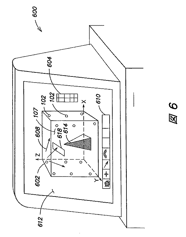
「my_lights」ファイルの各ラインは、1つのReal_Lightを表わします。各Real_Lightインスタンスは、1つの実世界ライトを表します。
モニタの左および右側の下部ライトは、インジケータ0および2であり、モニタ左側の中央ライトは、インジケータ1です。
位置の値は、メートル単位です。Zはモニタの面の、内外の方向です。Xはモニタの面内で垂直方向、Yはモニタの面内で水平方向です。
MAX_LIGHTSは、それぞれのDMX世界に対して、最高170です。各DMX世界は、通常、コンピュータ(例えば、COM1)への単一の物理的接続です。MAX_LIGHTSは、DMX(MAX_LIGHTS*3)に送られるバッファの大きさを決定するので、MAX_LIGHTSが大きくなるほど、ライトの応答は遅くなります。もちろん、大きなバッファは送出時間が長くかかります。
OVERALL_GAMMAは、0〜1の値をとることができます。この値は、DirectLight中に読み込まれ、実行時間中に変更することができます。
Configuration file
The file “my_lights.h” contains information about real world lights and is loaded into DirectLight at startup. The files “my_lights.h” and “light_definition.h” must be included in the same directory as the application that uses DirectLights.
“My_lights.h” is created and edited by the DirectLight GUI Setup program. For details on how to use this program, please refer to the online help in the program.
Below is an example of a “my_lights.h” file.
Each line in the “my_lights” file represents one Real_Light. Each Real_Light instance represents one real world light.
The lower lights on the left and right sides of the monitor are indicators 0 and 2, and the center light on the left side of the monitor is indicator 1.
The position value is in meters. Z is the inside / outside direction of the monitor surface. X is vertical in the plane of the monitor and Y is horizontal in the plane of the monitor.
MAX_LIGHTS is a maximum of 170 for each DMX world. Each DMX world is usually a single physical connection to a computer (eg, COM1). MAX_LIGHTS determines the size of the buffer sent to DMX (MAX_LIGHTS * 3), so the larger the MAX_LIGHTS, the slower the light response. Of course, a large buffer takes longer to send.
OVERALL_GAMMA can take a value between 0 and 1. This value is read into DirectLight and can be changed during runtime.
これまで本発明のいくつかの実証的な実施態様について記述したが、当業者であれば、様々な変更、修正および改善を容易に思いつくであろう。そのような変更形態、修正形態、および改善形態は本発明の趣旨と範囲に含まれることを意図するものである。したがって、以上の記述は、例としてためだけのものであり、限定を意図するものではない。本発明は、添付の請求項およびその等価物に定義される内容によってのみ限定されるものである。 While several empirical embodiments of the present invention have been described above, various changes, modifications and improvements will readily occur to those skilled in the art. Such alterations, modifications, and improvements are intended to be included within the spirit and scope of the invention. Accordingly, the foregoing description is by way of example only and is not intended as limiting. The invention is limited only as defined in the appended claims and the equivalents thereto.
Claims (58)
無線通信信号を送信するように適合された送信機を提供するステップと、
複数のライトシステムの位置を特定するマップファイルを生成するステップと、
前記送信機から前記複数のライトシステムにマップファイルに基づいた少なくとも1つのライティング制御信号を送信するステップと、
前記少なくとも1つのライティング制御信号に応答して、前記複数のライトシステムの少なくとも第1のライトシステムおよび第2のライトシステムからのそれぞれの光出力を生成するステップとを含み、文字、図形、視覚的模様または絵を含む、視認される光によって形成された視覚的に連係した効果を発生させる方法。 Providing a plurality of uniquely addressable LED light systems each having a dedicated wireless receiver adapted to receive wireless communications;
Providing a transmitter adapted to transmit a wireless communication signal;
Generating a map file that identifies the location of multiple light systems;
Transmitting at least one lighting control signal based on a map file from the transmitter to the plurality of light systems;
Generating at least one light output from at least a first light system and a second light system of the plurality of light systems in response to the at least one lighting control signal; A method of generating visually linked effects formed by visible light, including patterns or pictures.
た効果を発生させるものである、装置。 An apparatus comprising a unique addressable LED light system having a dedicated wireless receiver adapted to receive wireless communication and at least one LED, the LED light system from the received wireless communication It is configured to read a lighting control signal and generate radiation in response to the lighting control signal, wherein the lighting control signal is generated by means for generating a map file that identifies the location of a plurality of LED light systems. Based on a map file, the radiation cooperates with other light systems to produce visually coordinated effects formed by visible light, including letters, graphics, visual patterns or pictures. A device that is generated.
Applications Claiming Priority (6)
| Application Number | Priority Date | Filing Date | Title |
|---|---|---|---|
| US29782801P | 2001-06-13 | 2001-06-13 | |
| US30169201P | 2001-06-28 | 2001-06-28 | |
| US31245601P | 2001-08-15 | 2001-08-15 | |
| US09/971,367 US6788011B2 (en) | 1997-08-26 | 2001-10-04 | Multicolored LED lighting method and apparatus |
| US32886701P | 2001-10-12 | 2001-10-12 | |
| US34147601P | 2001-10-30 | 2001-10-30 |
Related Parent Applications (1)
| Application Number | Title | Priority Date | Filing Date |
|---|---|---|---|
| JP2003504372A Division JP2004534356A (en) | 2001-06-13 | 2002-06-13 | System and method for controlling a light system |
Publications (1)
| Publication Number | Publication Date |
|---|---|
| JP2009070832A true JP2009070832A (en) | 2009-04-02 |
Family
ID=40606821
Family Applications (1)
| Application Number | Title | Priority Date | Filing Date |
|---|---|---|---|
| JP2009001685A Pending JP2009070832A (en) | 2001-06-13 | 2009-01-07 | System and method for controlling light system |
Country Status (2)
| Country | Link |
|---|---|
| JP (1) | JP2009070832A (en) |
| AU (1) | AU2002310434A1 (en) |
Cited By (10)
| Publication number | Priority date | Publication date | Assignee | Title |
|---|---|---|---|---|
| US8203281B2 (en) | 2008-04-29 | 2012-06-19 | Ivus Industries, Llc | Wide voltage, high efficiency LED driver circuit |
| JP2012524378A (en) * | 2009-04-20 | 2012-10-11 | エルエスアイ・インダストリーズ・インコーポレーテッド | Lighting technique for wirelessly controlling lighting elements |
| JP2012524375A (en) * | 2009-04-20 | 2012-10-11 | エルエスアイ・インダストリーズ・インコーポレーテッド | Lighting technique for wirelessly controlling lighting elements |
| JP2014116106A (en) * | 2012-12-06 | 2014-06-26 | Kyoraku Sangyo Co Ltd | Portable light-emitting device |
| WO2015002137A1 (en) * | 2013-07-02 | 2015-01-08 | チームラボ株式会社 | Stage lighting method and stage lighting system |
| JP2015507831A (en) * | 2012-01-20 | 2015-03-12 | コーニンクレッカ フィリップス エヌ ヴェ | Method for detecting and controlling an encoded light source |
| JP2017157549A (en) * | 2016-02-29 | 2017-09-07 | ハナムアーテック シーオー., エルティーディーHanam Artec Co., Ltd | Master device and slave device constituting emission control system |
| US11096263B2 (en) | 2019-04-22 | 2021-08-17 | Beatro Co., Ltd. | Method and device for controlling a plurality of wireless lighting devices |
| US11532131B2 (en) * | 2010-06-15 | 2022-12-20 | Live Nation Entertainment, Inc. | Generating augmented reality images using sensor and location data |
| KR102500409B1 (en) * | 2021-11-19 | 2023-02-16 | 사단법인 한국건물에너지기술원 | Method and apparatus for positioning smart lighting device |
Citations (8)
| Publication number | Priority date | Publication date | Assignee | Title |
|---|---|---|---|---|
| JPS6240101A (en) * | 1985-08-16 | 1987-02-21 | 株式会社 工科舎 | Stage production |
| JPH06133367A (en) * | 1992-09-23 | 1994-05-13 | Walt Disney Co:The | Method and apparatus for remote synchronization of audio, illumination, animation and special effect |
| JPH0935876A (en) * | 1995-07-20 | 1997-02-07 | Matsushita Electric Works Ltd | Lighting relay, luminaire and lighting system |
| JPH10207391A (en) * | 1997-01-27 | 1998-08-07 | Kodera Denshi Seisakusho:Kk | Image display device |
| JPH11135269A (en) * | 1997-10-31 | 1999-05-21 | Toshiba Lighting & Technology Corp | Remote control device and its monitoring device |
| JPH11273875A (en) * | 1998-03-24 | 1999-10-08 | Mitsubishi Electric Corp | Lighting control system |
| JP2000195681A (en) * | 1998-12-28 | 2000-07-14 | Toshiba Lighting & Technology Corp | Dimmer control system, radio transmitting unit and radio dimming device |
| JP2000260212A (en) * | 1999-03-04 | 2000-09-22 | Riido International Kk | System comprising transmitter and receiver emitting light |
-
2002
- 2002-06-13 AU AU2002310434A patent/AU2002310434A1/en not_active Abandoned
-
2009
- 2009-01-07 JP JP2009001685A patent/JP2009070832A/en active Pending
Patent Citations (8)
| Publication number | Priority date | Publication date | Assignee | Title |
|---|---|---|---|---|
| JPS6240101A (en) * | 1985-08-16 | 1987-02-21 | 株式会社 工科舎 | Stage production |
| JPH06133367A (en) * | 1992-09-23 | 1994-05-13 | Walt Disney Co:The | Method and apparatus for remote synchronization of audio, illumination, animation and special effect |
| JPH0935876A (en) * | 1995-07-20 | 1997-02-07 | Matsushita Electric Works Ltd | Lighting relay, luminaire and lighting system |
| JPH10207391A (en) * | 1997-01-27 | 1998-08-07 | Kodera Denshi Seisakusho:Kk | Image display device |
| JPH11135269A (en) * | 1997-10-31 | 1999-05-21 | Toshiba Lighting & Technology Corp | Remote control device and its monitoring device |
| JPH11273875A (en) * | 1998-03-24 | 1999-10-08 | Mitsubishi Electric Corp | Lighting control system |
| JP2000195681A (en) * | 1998-12-28 | 2000-07-14 | Toshiba Lighting & Technology Corp | Dimmer control system, radio transmitting unit and radio dimming device |
| JP2000260212A (en) * | 1999-03-04 | 2000-09-22 | Riido International Kk | System comprising transmitter and receiver emitting light |
Cited By (18)
| Publication number | Priority date | Publication date | Assignee | Title |
|---|---|---|---|---|
| US8203281B2 (en) | 2008-04-29 | 2012-06-19 | Ivus Industries, Llc | Wide voltage, high efficiency LED driver circuit |
| JP2012524378A (en) * | 2009-04-20 | 2012-10-11 | エルエスアイ・インダストリーズ・インコーポレーテッド | Lighting technique for wirelessly controlling lighting elements |
| JP2012524375A (en) * | 2009-04-20 | 2012-10-11 | エルエスアイ・インダストリーズ・インコーポレーテッド | Lighting technique for wirelessly controlling lighting elements |
| US8628198B2 (en) | 2009-04-20 | 2014-01-14 | Lsi Industries, Inc. | Lighting techniques for wirelessly controlling lighting elements |
| US11532131B2 (en) * | 2010-06-15 | 2022-12-20 | Live Nation Entertainment, Inc. | Generating augmented reality images using sensor and location data |
| JP2015507831A (en) * | 2012-01-20 | 2015-03-12 | コーニンクレッカ フィリップス エヌ ヴェ | Method for detecting and controlling an encoded light source |
| JP2014116106A (en) * | 2012-12-06 | 2014-06-26 | Kyoraku Sangyo Co Ltd | Portable light-emitting device |
| WO2015002137A1 (en) * | 2013-07-02 | 2015-01-08 | チームラボ株式会社 | Stage lighting method and stage lighting system |
| JP2015011981A (en) * | 2013-07-02 | 2015-01-19 | チームラボ株式会社 | Illumination presentation method and illumination presentation system |
| JP2017157549A (en) * | 2016-02-29 | 2017-09-07 | ハナムアーテック シーオー., エルティーディーHanam Artec Co., Ltd | Master device and slave device constituting emission control system |
| US10509930B2 (en) | 2016-02-29 | 2019-12-17 | Hanam Artec Co., Ltd. | Lighting control system using barcode information |
| US10762315B2 (en) | 2016-02-29 | 2020-09-01 | Hanam Artec Co., Ltd. | Lighting control system using barcode information |
| US11350258B2 (en) | 2016-02-29 | 2022-05-31 | Hanam Artec Co., Ltd. | Lighting control system using barcode information |
| US10387700B2 (en) | 2016-02-29 | 2019-08-20 | Hanam Artec Co., Ltd. | Emission control system using barcode information |
| US11638137B2 (en) | 2016-02-29 | 2023-04-25 | Hanam Artec Co., Ltd. | Lighting control system using barcode information |
| US11924729B2 (en) | 2016-02-29 | 2024-03-05 | Hanam Artec Co., Ltd. | Lighting control system using barcode information |
| US11096263B2 (en) | 2019-04-22 | 2021-08-17 | Beatro Co., Ltd. | Method and device for controlling a plurality of wireless lighting devices |
| KR102500409B1 (en) * | 2021-11-19 | 2023-02-16 | 사단법인 한국건물에너지기술원 | Method and apparatus for positioning smart lighting device |
Also Published As
| Publication number | Publication date |
|---|---|
| AU2002310434A1 (en) | 2002-12-23 |
Similar Documents
| Publication | Publication Date | Title |
|---|---|---|
| US7242152B2 (en) | Systems and methods of controlling light systems | |
| US7231060B2 (en) | Systems and methods of generating control signals | |
| JP2004534356A (en) | System and method for controlling a light system | |
| ES2343964T3 (en) | LIGHT SYSTEM MANAGER. | |
| JP4173091B2 (en) | System and method for generating control signals | |
| JP2009070832A (en) | System and method for controlling light system | |
| JP4652691B2 (en) | Method and apparatus for controlled light emission | |
| ES2814649T3 (en) | Tile lighting procedures and systems | |
| EP1729615B1 (en) | Entertainment lighting system | |
| US7202613B2 (en) | Controlled lighting methods and apparatus | |
| US7358929B2 (en) | Tile lighting methods and systems | |
| US20050275626A1 (en) | Entertainment lighting system | |
| US20070176926A1 (en) | Lighting states in a computer aided design | |
| US20200257831A1 (en) | Led lighting simulation system | |
| WO2023090085A1 (en) | Illumination control device, illumination staging system, and illumination control method | |
| Cohn | Photorealistic Rendering Techniques in AutoCAD® 3D |
Legal Events
| Date | Code | Title | Description |
|---|---|---|---|
| A521 | Written amendment |
Free format text: JAPANESE INTERMEDIATE CODE: A523 Effective date: 20090206 |
|
| A621 | Written request for application examination |
Free format text: JAPANESE INTERMEDIATE CODE: A621 Effective date: 20090206 |
|
| A977 | Report on retrieval |
Free format text: JAPANESE INTERMEDIATE CODE: A971007 Effective date: 20110325 |
|
| A131 | Notification of reasons for refusal |
Free format text: JAPANESE INTERMEDIATE CODE: A131 Effective date: 20110331 |
|
| A521 | Written amendment |
Free format text: JAPANESE INTERMEDIATE CODE: A523 Effective date: 20110630 |
|
| A02 | Decision of refusal |
Free format text: JAPANESE INTERMEDIATE CODE: A02 Effective date: 20120105 |