JP2009049522A - Communication system, communication apparatus and communication control method - Google Patents
Communication system, communication apparatus and communication control method Download PDFInfo
- Publication number
- JP2009049522A JP2009049522A JP2007211503A JP2007211503A JP2009049522A JP 2009049522 A JP2009049522 A JP 2009049522A JP 2007211503 A JP2007211503 A JP 2007211503A JP 2007211503 A JP2007211503 A JP 2007211503A JP 2009049522 A JP2009049522 A JP 2009049522A
- Authority
- JP
- Japan
- Prior art keywords
- communication device
- wireless usb
- communication
- wireless
- beacon
- Prior art date
- Legal status (The legal status is an assumption and is not a legal conclusion. Google has not performed a legal analysis and makes no representation as to the accuracy of the status listed.)
- Pending
Links
Images


Classifications
-
- H—ELECTRICITY
- H04—ELECTRIC COMMUNICATION TECHNIQUE
- H04W—WIRELESS COMMUNICATION NETWORKS
- H04W16/00—Network planning, e.g. coverage or traffic planning tools; Network deployment, e.g. resource partitioning or cells structures
- H04W16/14—Spectrum sharing arrangements between different networks
-
- H—ELECTRICITY
- H04—ELECTRIC COMMUNICATION TECHNIQUE
- H04B—TRANSMISSION
- H04B1/00—Details of transmission systems, not covered by a single one of groups H04B3/00 - H04B13/00; Details of transmission systems not characterised by the medium used for transmission
- H04B1/06—Receivers
- H04B1/10—Means associated with receiver for limiting or suppressing noise or interference
- H04B1/109—Means associated with receiver for limiting or suppressing noise or interference by improving strong signal performance of the receiver when strong unwanted signals are present at the receiver input
Abstract
Description
本発明は、ネットワークにおける通信制御技術に関するものである。 The present invention relates to a communication control technique in a network.
10メートル程度の極近距離に配置された機器どうしを無線接続する方式はWPANと呼ばれ、WLANと区別して定義されている。 A method of wirelessly connecting devices arranged at an extremely short distance of about 10 meters is called WPAN, and is defined separately from WLAN.
現在、WPANに関しては、UWB(Ultra Wide Band)通信方式を使用するものとして、標準規格策定団体であるECMA internationalが、物理層およびMAC層の仕様をECMA−368標準規格として定義している。更にこのECMA−368標準規格の上位層で動作するプロトコルとして、Wireless USB規格などが定義されている。 Currently, ECMA international, which is a standard-developing organization, defines the specifications of the physical layer and the MAC layer as the ECMA-368 standard, using the UWB (Ultra Wide Band) communication system for WPAN. Further, the Wireless USB standard is defined as a protocol that operates in an upper layer of the ECMA-368 standard.
UWB通信方式の場合、複数の無線端末が同時に無線フレームを送信することにより発生する無線フレームの“衝突”を防止するために、各無線端末が他の無線端末へアクセスするタイミングを制御する。この制御方式を定めたものがMedia Access Control(MAC)プロトコルであり、ビーコンを送受信することにより当該制御を実現している。 In the case of the UWB communication system, in order to prevent a “collision” of radio frames generated when a plurality of radio terminals transmit radio frames at the same time, the timing at which each radio terminal accesses another radio terminal is controlled. This control method is defined by the Media Access Control (MAC) protocol, which realizes the control by transmitting and receiving beacons.
UWB通信方式の場合、周波数共用による無線通信システム間の“干渉”の問題がある。 In the case of the UWB communication system, there is a problem of “interference” between radio communication systems due to frequency sharing.
無線通信システム間の“干渉”の発生を抑制するためには、それぞれの無線通信システム内において無線端末の受信感度を調整することが有効であり、従来より、種々の受信感度調整方法が提案されている。 In order to suppress the occurrence of “interference” between wireless communication systems, it is effective to adjust the reception sensitivity of wireless terminals in each wireless communication system, and various reception sensitivity adjustment methods have been proposed. ing.
例えば、下記特許文献1では、自局の属する無線通信ネットワークの無線基地局の無線通信信号のみを検出するように、干渉信号に基づいて受信感度を調整する方法が提案されている。
For example,
また、下記特許文献2では、電波干渉測定テストを行い、測定された受信電界強度に基づいて、受信感度を調整する方法が提案されている。
しかしながら、上記特許文献1の場合、同一の無線通信ネットワークに属する無線基地局以外の他の無線端末(つまり、干渉に影響を与えない無線端末)からの無線通信信号をも排除することとなってしまう。このため、同一の無線通信ネットワークに属する他の無線端末の配置によっては、受信感度が著しく低く設定されてしまう可能性がある。
However, in the case of
一般に受信感度は、干渉が生じない範囲で極力高く設定しておくことが、通信の安定性が得られることから、受信感度が必要以上に低く設定されることは望ましくない。 Generally, it is not desirable that the reception sensitivity is set to be lower than necessary because it is possible to set the reception sensitivity as high as possible within a range in which interference does not occur.
一方、上記特許文献2に記載の受信感度調整方法によれば、干渉測定の結果に基づいて、それぞれの無線端末に適した受信感度を設定することができる。しかし、調整にあたっては、すべての無線端末について同時に干渉測定を行う必要があり、受信感度の調整に多大な労力を要するという問題がある。
On the other hand, according to the reception sensitivity adjustment method described in
本発明は、他のネットワークとの干渉を低減することを目的とする。 An object of the present invention is to reduce interference with other networks.
上記の目的を達成するために本発明に係る通信装置の一形態である制御局は以下のような構成を備える。即ち、
従属局が受信する信号に関する情報を前記従属局に送信させ、前記従属局が他のネットワークの通信装置から送信された信号を受信するか否かを判定する判定手段と、前記判定手段による判定の結果に基づいて、前記従属局に対して受信感度の変更を指示する指示手段と、を備える。
In order to achieve the above object, a control station which is an embodiment of a communication apparatus according to the present invention has the following configuration. That is,
Determining means for transmitting information on a signal received by a dependent station to the dependent station, and determining whether the dependent station receives a signal transmitted from a communication device of another network; and determining by the determining means Instruction means for instructing the dependent station to change reception sensitivity based on the result.
本発明によれば、他のネットワークとの干渉を低減することが可能となる。 According to the present invention, it is possible to reduce interference with other networks.
以下、図面を参照しながら各実施形態の詳細について説明する。なお、以下の説明においては、UWBを用いた無線通信ネットワークの一例として、Wireless USB規格を用いる場合について説明する。ただし、本発明はこれに限定されるものではなく、他のアプリケーションにより実現しても良い。 Details of each embodiment will be described below with reference to the drawings. In the following description, a case where the Wireless USB standard is used will be described as an example of a wireless communication network using UWB. However, the present invention is not limited to this, and may be realized by other applications.
また、以下の説明において、制御局とは、無線通信システムにおいて無線通信ネットワークを構築した場合に、通信を制御する端末であり、Wireless USB規格の場合にあっては、Wireless USBホストのことを意味するものとする。また、従属局とは、無線通信システムの制御局による制御のもとで通信を行う端末であり、Wireless USBの場合にあっては、Wireless USBデバイスのことを意味するものとする。なお、制御局と従属局とを総称して、無線端末と称することとする。 In the following description, a control station is a terminal that controls communication when a wireless communication network is constructed in a wireless communication system. In the case of the Wireless USB standard, it means a wireless USB host. It shall be. The dependent station is a terminal that performs communication under the control of the control station of the wireless communication system, and in the case of Wireless USB, it means a Wireless USB device. The control station and the dependent stations are collectively referred to as a wireless terminal.
[第1の実施形態]
1.UWBのMACプロトコルにおける無線フレームの説明
はじめに、UWB通信方式のMACプロトコルにより規定される無線フレームの構成について説明する。
(1)無線フレームの全体構成
図1はMACプロトコルにより規定される無線フレームの全体構成を示した図である。MACプロトコルでは繰り返し生成される固定時間長のスーパーフレームを基準として無線端末間のアクセスのタイミングが制御される。
[First Embodiment]
1. Description of Radio Frame in UWB MAC Protocol First, the configuration of a radio frame defined by the UWB communication system MAC protocol will be described.
(1) Overall Configuration of Radio Frame FIG. 1 is a diagram showing the overall configuration of a radio frame defined by the MAC protocol. In the MAC protocol, the access timing between wireless terminals is controlled based on a repetitively generated superframe having a fixed time length.
スーパーフレームの時間長は約65ミリ秒であり、更にこのスーパーフレームは256個のタイムスロットに等間隔に分割されている。これらタイムスロットのうちデータ通信に使用されるデータ通信用タイムスロットの使用権の調停は、無線端末が互いにビーコンとよばれる制御信号を送受信することによって実現される。 The time length of the super frame is about 65 milliseconds, and this super frame is further divided into 256 time slots at equal intervals. Of these time slots, arbitration of the right to use data communication time slots used for data communication is realized by wireless terminals transmitting and receiving control signals called beacons to each other.
スーパーフレームの開始部分に位置する1個以上のタイムスロットは、無線端末がこのビーコンを送信するための領域として確保されたものであり、当該領域はビーコンピリオドと呼ばれている。
(2)無線フレームに含まれるビーコンピリオドの構成
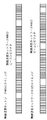
図2は無線フレームに含まれるビーコンピリオドの構成を示した図である。ビーコンピリオドは、約85マイクロ秒の長さを持つ複数のビーコンスロットから構成されている。ビーコンピリオドの長さは無線端末数に依存しており、可変長である。
One or more time slots located at the start of the superframe are reserved as an area for the wireless terminal to transmit this beacon, and this area is called a beacon period.
(2) Configuration of beacon period included in radio frame FIG. 2 is a diagram illustrating a configuration of a beacon period included in a radio frame. The beacon period is composed of a plurality of beacon slots having a length of about 85 microseconds. The length of the beacon period depends on the number of wireless terminals and is variable.
ビーコンピリオドの開始時点はBPST(Beacon Period Start Time)と呼ばれている。このBPSTは、言い換えればスーパーフレームの開始時点でもある。 The start time of the beacon period is called BPST (Beacon Period Start Time). In other words, this BPST is also the start time of the superframe.
1つの無線通信ネットワークを構築する複数の無線端末は、互いにスーパーフレームの開始時点に相当するBPSTを共有しており、それゆえ、各無線端末が送信するビーコンは、以下のような構成となっている。
(3)ビーコンの構成
図3はMACプロトコルに従って送信されるビーコンの構成を示す模式図である。図3に示すように、各無線端末は自局のビーコン内に、自局のアドレスおよび自局がビーコン送信のために使用しているビーコンスロット番号を備える(301、302)。
A plurality of wireless terminals constructing one wireless communication network share a BPST corresponding to the start time of the superframe with each other. Therefore, a beacon transmitted by each wireless terminal has the following configuration. Yes.
(3) Beacon Configuration FIG. 3 is a schematic diagram showing the configuration of a beacon transmitted according to the MAC protocol. As shown in FIG. 3, each wireless terminal is provided with its own address and the beacon slot number that it uses for beacon transmission in its own beacon (301, 302).
ビーコンを受信した他の無線端末は、ビーコンの内容を解析し、実際にビーコンを受信した時点とビーコンに含まれているビーコンスロット番号(302)とに基づいて、ビーコン送信した無線端末が認識しているBPSTの時点を算出することができる。 The other wireless terminal that has received the beacon analyzes the contents of the beacon and recognizes the wireless terminal that transmitted the beacon based on the time when the beacon was actually received and the beacon slot number (302) included in the beacon. It is possible to calculate the time point of BPST.
このように無線端末は他の無線端末が認識しているBPSTの開始時点を判定することができるため、このBPSTをスーパーフレームの開始基準点とすることで、互いに同期したアクセスを行うことができる。 As described above, since the wireless terminal can determine the start point of BPST recognized by other wireless terminals, the BPST can be used as a start reference point of the superframe to perform access synchronized with each other. .
更に、各無線端末は自局のビーコン内に、認識している他の無線端末のアドレスをスロット番号ごとに格納したビーコンスロット占有情報303を備える。これにより、ビーコンスロットの衝突を回避することが可能となっている。
Further, each wireless terminal includes beacon
なお、図3の例では、ビーコンに含まれる情報として本実施形態の説明に必要となるもののみを示している。このため、ECMA−368標準規格などで実際に定義されるビーコンのフレームフォーマットとは異なっているが、これは、図3で示された情報以外の情報を排除することを意図したものではない。 In the example of FIG. 3, only information necessary for the description of the present embodiment is shown as information included in the beacon. For this reason, it is different from the beacon frame format actually defined in the ECMA-368 standard or the like, but this is not intended to exclude information other than the information shown in FIG.
2.無線通信システムの構成
図4は、本発明の第1の実施形態に係る無線端末により構築された無線通信ネットワーク群の構成を示す図である。図4に示す各無線端末は、UWBを用いたWireless USBにより無線通信ネットワーク400、410をそれぞれ構築しているものとする。
2. Configuration of Radio Communication System FIG. 4 is a diagram showing a configuration of a radio communication network group constructed by radio terminals according to the first embodiment of the present invention. Assume that each wireless terminal shown in FIG. 4 has built
図4に示すように、401はWireless USBホスト(制御局)、402、403はWireless USBデバイス(従属局)であり、両者は無線通信ネットワーク400を構築している。同様に、411はWireless USBホスト(制御局)、412はWireless USBデバイス(従属局)であり、両者は無線通信ネットワーク400とは異なる他の無線通信ネットワーク410を構築している。
As shown in FIG. 4, 401 is a wireless USB host (control station), 402 and 403 are wireless USB devices (subordinate stations), and both construct a
無線通信ネットワーク400と410とは、それぞれ以下のような構成を有している。まず、スーパーフレームとして、無線通信ネットワーク400および無線通信ネットワーク410は、図5に示すように、異なる時点をBPSTおよびビーコンピリオドとして設定している。なお、このような関係を、“非同期”と呼び、非同期の無線端末間ではデータ通信することはない。
Each of the
また、各無線端末より送信されるビーコンは、図6に示すような設定がなされている。つまり、Wireless USBホストならびにWireless USBデバイス(401、402、403、411、412)にはそれぞれ2番目〜6番目の異なるビーコンスロットが割り当てられている。 In addition, the beacons transmitted from the wireless terminals are set as shown in FIG. That is, the second to sixth different beacon slots are assigned to the wireless USB host and the wireless USB devices (401, 402, 403, 411, 412), respectively.
なお、0番目および1番目のビーコンスロットが使用されていないのは、WiMedia標準規格ではこれら2つのビーコンスロットはビーコンピリオド長の最適化処理という他の目的のために利用されるからである。ただし、これは本発明と本質的に関連するものではない。 Note that the 0th and 1st beacon slots are not used because the WiMedia standard uses these two beacon slots for other purposes such as optimization of the beacon period length. However, this is not essentially related to the present invention.
図6に示すように、Wireless USBホスト401はWireless USBデバイス402、403のビーコンを受信しているため、ビーコンスロット占有情報としてスロット番号3、4に、当該デバイスのアドレスが各々格納されている。更に自局がビーコン送信しているスロット番号2には自局のアドレスが格納されており、その他のスロット番号に対応するフィールドは空白となっている。なお、Wireless USBデバイス403のビーコンスロット占有情報も基本的には同様の設定となっている。
As shown in FIG. 6, since the
また、Wireless USBホスト411はWireless USBデバイス412のビーコンを受信しているため、ビーコンスロット占有情報としてスロット番号6にはWireless USBデバイス412のアドレスが格納されている。更に自局がビーコン送信しているスロット番号5には自局のアドレスが格納されており、その他のスロット番号に対応するフィールドは空白となっている。なお、Wireless USBデバイス412のビーコンスロット占有情報も基本的には同様の設定となっている。
Since the
一方、Wireless USBデバイス402はWireless USBホスト401、Wireless USBデバイス403に加え、Wireless USBデバイス412のビーコンを受信しているものとする。このため、ビーコンスロット占有情報としてスロット番号2、4、6には、当該デバイスのアドレスがそれぞれ格納されている。更に自局がビーコン送信しているスロット番号3には自局のアドレスが格納されており、その他のスロット番号に対応するフィールドは空白となっている。
On the other hand, it is assumed that the
3.制御局の内部構成
図7は制御局の内部構成の一例を示す図であり、図7を参照しながら、制御局を構成する各部の動作について簡単に説明する。なお、ここでは、制御局としてWireless USBホスト401について説明するが、Wireless USBホスト411についても同様の内部構成を有しているものとする。
3. Internal Configuration of Control Station FIG. 7 is a diagram showing an example of the internal configuration of the control station. The operation of each unit constituting the control station will be briefly described with reference to FIG. Here, the
Wireless USBホスト401が送信する無線フレームには以下の種類のフレームがある。
The wireless frame transmitted by the
・アプリケーションデータを伝送するためのデータフレーム
・ビーコンプロトコル処理のためのビーコンフレーム
・Wireless USBデバイス402(及び403)を制御するために使用されるリクエストフレーム
このうち、データフレームの送受信は次のような手順で実行される。すなわち、まず送信されるアプリケーションデータがアプリケーション処理部701から送信データアプリケーションインターフェース部703を経由してデータフレーム生成部704に伝えられる。次に、当該アプリケーションデータが、データフレーム生成部704において無線通信に適したフォーマットを持つデータフレームに変換される。
-Data frame for transmitting application data-Beacon frame for beacon protocol processing-Request frame used to control Wireless USB device 402 (and 403) Of these, the transmission and reception of data frames are as follows Performed in steps. That is, first, application data to be transmitted is transmitted from the
その後、送信フレーム選択部705において当該データフレームが選択されると、変調部706でアナログ信号に変換され、更に高周波部707において無線信号に変換され、アンテナ708からWireless USBデバイス402へと送信される。
Thereafter, when the transmission
一方、アンテナ708で受信され高周波部707においてベースバンド信号あるいはデジタル信号に変換されたデータフレームは、復調部711でデータ復調され、受信フレーム解析部710に送られる。
On the other hand, the data frame received by the
受信フレーム解析部710では、入力された無線フレームがデータフレームであると判断すると、アプリケーションデータとして適切なフォーマットに変換する。そして、該アプリケーションデータを受信データアプリケーションインターフェース部709を介してアプリケーション処理部701に引き渡す。
When the received
一方、ビーコンフレームやリクエストフレームの送受信には、MACプロトコル処理部702が利用される。
On the other hand, the MAC
MACプロトコル処理部702には、ビーコンプロトコルを実施するためのビーコンフレームの送受信機能が含まれている。更にWireless USBデバイス402を制御するためのリクエストフレームの生成機能や、リクエストフレームに対応してWireless USBデバイス402から受信したレスポンスフレームの解析機能も含まれている。このため、受信フレーム解析部710において、入力された無線フレームがビーコンフレームまたはリクエストフレームであると判断された場合には、該受信フレームはMACプロトコル処理部702に引き渡される。以下、MACプロトコル処理部702の上記機能について説明する。
The MAC
4.MACプロトコル処理部の内部構成
図8は、Wireless USBホスト401に具備されるMACプロトコル処理部702の内部構成例を示した図である。MACプロトコル処理部702において実現される機能は、以下の2つの機能に大別することができる。
・すでに接続状態にある他の従属局(Wireless USBデバイス403)との通信において実行されるビーコンフレーム送受信機能
・これから接続され、現在、待機状態にある他の従属局(Wireless USBデバイス402)との通信において実行される機能
なお、待機状態とは、新たに起動された従属局(ここでは、Wireless USBデバイス402)が制御局(ここでは、Wireless USBホスト401)に接続されるまでの間の遷移状態をいうものとする。
(1)接続状態における機能
Wireless USBホスト401が、Wireless USBデバイス403から送信されたビーコンを受信した場合、受信したビーコンは、ビーコン/レスポンス判定部811からビーコン解析部808へと送られる。
4). Internal Configuration of MAC Protocol Processing Unit FIG. 8 is a diagram illustrating an internal configuration example of the MAC
-Beacon frame transmission / reception function executed in communication with another dependent station (Wireless USB device 403) that is already connected-With another dependent station (Wireless USB device 402) that is now connected and is in a standby state Functions executed in communication Note that the standby state is a transition until a newly activated dependent station (here, the Wireless USB device 402) is connected to the control station (here, the Wireless USB host 401). It shall refer to the state.
(1) Function in Connected State When the
ビーコン解析部808では受信したビーコンの内容を解析し、その解析結果をビーコンプロトコル処理部807へと伝える。ビーコンプロトコル処理部807では、ビーコンプロトコルに従って、受信したビーコンの内容とタイミングとを基準として、自局が送信するビーコンを生成するために必要なパラメータを決定する。
The
ビーコンプロトコル処理部807にて決定されたパラメータはビーコン生成部805へ伝えられ、ビーコン生成部805において自局が送信するビーコンが生成される。生成されたビーコンはビーコン/リクエスト選択部806を経て、最終的にアンテナ708からWireless USBデバイス403へと送信される。
(2)待機状態における機能
待機状態にある従属局(Wireless USBデバイス402)との通信では、従属局制御部801が動作する。従属局制御部801は、Wireless USBデバイス402の動作(ビーコン傍受、ビーコン転送、受信感度設定)を制御するための処理を行う。
The parameters determined by the beacon
(2) Function in Standby State In the communication with the dependent station (Wireless USB device 402) in the standby state, the dependent
従属局制御部801が指示することにより、従属局リクエスト設定部803では、従属局(ここでは、Wireless USBデバイス402)に送信すべきリクエストを設定する。また、従属局受信感度設定部802では従属局(ここでは、Wireless USBデバイス402)が受信する際の受信感度を決定する。
When the dependent
これらの処理を踏まえて、リクエスト生成部804では、Wireless USBデバイス402に対してビーコン傍受、ビーコン転送、受信感度設定の各指示を行う際に用いられるリクエストフレームを生成する。
Based on these processes, the
そして、その応答としてWireless USBデバイス402からWireless USBホスト401が受信するレスポンスフレームは、レスポンス解析部810で解析される。
A response frame received by the
従属局制御部801では、レスポンス解析部810における解析結果に基づいて、従属局受信感度設定部802、従属局リクエスト設定部803に対する指示を行う。
The dependent
5.従属局の内部構成
図9は従属局の内部構成の一例を示す図であり、図9を参照しながら、従属局を構成する各部の動作について簡単に説明する。なお、ここでは、従属局としてWireless USBデバイス402について説明するが、Wireless USBデバイス403、412についても同様の内部構成を有しているものとする。
5). Internal Configuration of Dependent Station FIG. 9 is a diagram showing an example of the internal configuration of the dependent station. The operation of each part constituting the dependent station will be briefly described with reference to FIG. Here, the
制御局同様、従属局も、データフレームの送受信は次のような手順で実行される。すなわち、まず送信されるアプリケーションデータがアプリケーション処理部901から送信データアプリケーションインターフェース部903を経由してデータフレーム生成部904に伝えられる。次に当該アプリケーションデータが、データフレーム生成部904において無線通信に適したフォーマットを持つデータフレームに変換される。
Similar to the control station, the dependent station transmits and receives data frames in the following procedure. That is, first, application data to be transmitted is transmitted from the
その後、送信フレーム選択部905において当該データフレームが選択されると、変調部906でアナログ信号に変換され、更に高周波部907において無線信号に変換され、アンテナ908からWireless USBホスト401へと送信される。
Thereafter, when the transmission
一方、アンテナ908で受信され高周波部907においてベースバンド信号あるいはデジタル信号に変換されたデータフレームは、復調部912でデータ復調され、受信フレーム解析部913に送られる。
On the other hand, a data frame received by the
受信フレーム解析部913では、入力された無線フレームがデータフレームであると判断すると、アプリケーションデータとして適切なフォーマットに変換する。そして、該アプリケーションデータを受信データアプリケーションインターフェース部914を介してアプリケーション処理部901に引き渡す。
When the received
一方、受信フレーム解析部913において、入力された無線フレームがビーコンフレームまたはリクエストフレームであると判断すると、Wireless USBプロトコル処理部902へ送られる。
On the other hand, when the received
Wireless USBプロトコル処理部902では、ビーコンフレームを解析したり、リクエストフレームに対応する処理(例えば、受信感度設定信号910によって検波部909に対して受信感度を設定する処理)を実行したりする。
The Wireless USB
なお、Wireless USBデバイス402は、検波部909を具備しており、高周波部907から受け取った中間周波数帯の受信信号の受信電力レベルを判定することができる。
The
判定された結果はフレーム検出信号911としてWireless USBプロトコル処理部902へ送られる。
The determined result is sent as a
なお、ここでは権パブ909は高周波部907から受信信号として中間周波数帯の信号を受け取り検波することとしているが、実装形態によってはベースバンド周波数帯域の受信信号やディジタルデータに変換された受信信号を検波する構成としてもよい。
Here, the
6.制御局における状態遷移
図10は、Wireless USBデバイス402が待機状態にある場合の、Wireless USBホスト401の状態遷移を示した状態遷移図である。換言すると図10はWireless USBホスト401が、新たに起動されたWireless USBデバイス402を制御する際の制御処理を示している。
6). State Transition in Control Station FIG. 10 is a state transition diagram showing the state transition of the
Wireless USBデバイス402の制御は、Wireless USBホスト401がWireless USBデバイス402に対してリクエストを送ることにより実行される。このリクエストに従って処理を行ったWireless USBデバイス402では、当該リクエストに対応したレスポンスをWireless USBホスト401へ送ることによって、その処理の結果を通知する。図10に示すようにWireless USBホスト401は、4種類のリクエストにより待機状態のWireless USBデバイス402を制御する。
Control of the
1001はCountPacketsリクエストである。CountPacketsリクエストは、ビーコンの傍受を要求する。Wireless USBホスト401からCountPacketsリクエストを受け取ったWireless USBデバイス402では、ビーコンの傍受を開始する。
1002はCapturePacketリクエストである。CapturePacketリクエストは、受信したビーコンに関する情報を送信するよう要求する。CapturePacketリクエストを受け取ったWireless USBデバイス402では、このリクエストによって指定されたビーコンに関する情報をレスポンスとしてWireless USBホスト401に送信する。ビーコンに関する情報には、受信したビーコンのすべての内容、受信したタイミング、受信品質が含まれる。
つまり、CountPacketsリクエスト及びCapturePacketリクエストを利用することにより、Wireless USBホスト401はWireless USBデバイス402が受信したビーコンに関連する情報を知ることができる。
That is, by using the CountPackets request and the CapturePacket request, the
1003はTransmitPacketリクエストである。Wireless USBホスト401からTransmitPacketリクエストを受け取ったWireless USBデバイス402では、このリクエストによって指定された内容のビーコンを指定されたタイミングで送信する。TransmitPacketリクエストを利用することにより、Wireless USBホスト401はWireless USBデバイス402に対してビーコン送信を実行させることができる。
1004はSetWUSBDataリクエストである。Wireless USBデバイス402では、Wireless USBホスト401から、パラメータwValueがTransmitPowerに設定されたSetWUSBDataリクエストを受け取る。そして、自局がビーコンを受信するときに使用する受信感度をこのリクエストフレームによって指定された値に設定する。
つまり、SetWUSBDataリクエストを利用することにより、Wireless USBホスト401はWireless USBデバイス402の受信感度を制御することができる。
In other words, the
7.無線通信システム間の干渉についての説明
図11は、無線通信ネットワーク400と410との間の干渉を説明するための図である。図11の(A)では、Wireless USBデバイス402は起動していない。よって、Wireless USBデバイス402と、Wireless USBデバイス412とは、互いに通信することも、衝突することもなく、また、この状態では互いに干渉を与えることもない。
7). Description of Interference between Radio Communication Systems FIG. 11 is a diagram for explaining interference between
しかしながら、この状態で、Wireless USBデバイス402が起動すると、無線通信ネットワーク400と無線通信ネットワーク410との間で干渉が生じることとなる。
However, when the
起動したWireless USBデバイス402は、最初に、無線フレームの傍受を行い、周辺に自局が接続するべき制御局(ここでは、Wireless USBホスト401)が存在するかどうかを検知する。
The activated
そして、Wireless USBホスト401が送信した無線フレームを受信したとすると、Wireless USBデバイス402では、Wireless USBホスト401を接続すべき制御局と判定する。
Then, assuming that the wireless frame transmitted by the
この判定の結果、Wireless USBデバイス402はWireless USBホスト401に接続する。
As a result of this determination, the
接続が完了すると、Wireless USBホスト401はWireless USBデバイス402に対して、CountPacketsリクエストおよびCapturePacketリクエストを送信する。これにより、Wireless USBホスト401は、Wireless USBデバイス402の周辺環境に存在する他のWireless USBデバイスを検出する。
When the connection is completed, the
ここで図11(B)に示したように、Wireless USBデバイス402が受信可能な無線フレームの受信範囲1101内にはWireless USBデバイス412が含まれている。このため、Wireless USBデバイス412が送信するビーコンなどの無線フレームはWireless USBデバイス402に対して干渉を与えることになる。
Here, as illustrated in FIG. 11B, the
特にWireless USBデバイス412は、ビーコンのみならずデータ通信のために使用する他の無線フレームも無線通信ネットワーク410に同期したMACプロトコルタイミングで送信する。このため、これらの無線フレームはすべてWireless USBデバイス402が属する無線通信ネットワーク400に対して干渉を与える恐れがある。
In particular, the
そこで、本実施形態におけるWireless USBホスト401では、起動されたWireless USBデバイス402の受信感度を制御することで、無線通信ネットワーク410からの干渉の影響を回避することとしている。以下、Wireless USBホスト401における受信感度制御処理の流れについて詳細を説明する。
Therefore, the
8.制御局における干渉回避のための受信感度制御処理の流れ
図12は、Wireless USBデバイス402が原因で、無線通信ネットワーク410との間で干渉が生じることがないように、Wireless USBホスト401が実行する受信感度制御処理の流れを示す図である。
8). Flow diagram 12 of the receiving sensitivity control process in order to avoid interference control station, due to the
Wireless USBホスト401では、Wireless USBデバイス402から接続要求を受信すると、図12に示す受信感度制御処理を開始する。
When the
ステップS1201では、Wireless USBデバイス402が一定時間だけ無線フレームの傍受を行うよう、Wireless USBデバイス402に対してビーコン傍受リクエストを発行する。
In step S <b> 1201, a beacon interception request is issued to the
このビーコン傍受リクエストはWireless USBプロトコルにおいてはCountPacketsリクエストに相当するが、Wireless USBデバイス402のビーコンの傍受を起動させるものであれば特にこれに限定されない。
This beacon interception request corresponds to a CountPackets request in the Wireless USB protocol, but is not particularly limited as long as it activates beacon interception of the
ステップS1202では、このビーコン傍受リクエストで指定された時間が経過した後、Wireless USBデバイス402に対して、ビーコン転送リクエストを発行する。
In step S1202, a beacon transfer request is issued to the
なお、ビーコン転送リクエストはWireless USBプロトコルにおいてはCapturePacketリクエストに相当するが、特にこれに限定されるものではない。他の方式であっても受信したビーコンの内容をWireless USBホスト401へ転送するようWireless USBデバイス402に指示するものであればよい。
The beacon transfer request corresponds to a Capture Packet request in the Wireless USB protocol, but is not particularly limited to this. Any other method may be used as long as it instructs the
ビーコン転送リクエストに対するレスポンスとして、Wireless USBデバイス402は自局が受信したビーコンに関する情報をWireless USBホスト401へ転送する(送信手段)。そして、Wireless USBホスト401ではこれを受信する(受信手段)。なお、ビーコンに関する情報には、ビーコンを送信したそれぞれの無線端末のアドレスが含まれる。
As a response to the beacon transfer request, the
ステップS1203では、Wireless USBデバイス402から受信したビーコンに関する情報を解析する。なお、図11(B)の状態では、Wireless USBデバイス402の通信エリアには、Wireless USBホスト401と、Wireless USBデバイス402とが含まれる。更に、無線通信ネットワーク410に属するWireless USBデバイス412が含まれる。
In step S1203, information regarding the beacon received from the
したがって、Wireless USBデバイス402より送信されたビーコンに関する情報には、当該3つの無線端末のアドレスが含まれていることとなる。
Therefore, the information regarding the beacon transmitted from the
そこで、ステップS1203では、これら3つの無線端末のアドレスを、Wireless USBホスト401と同期して動作している無線端末のアドレスと、非同期に動作している無線端末のアドレスとに分類する。ここでは、Wireless USBホスト401と、Wireless USBデバイス402を同期端末に分類し、Wireless USBデバイス412を非同期端末に分類することになる。そして、以下、非同期に動作している無線端末が干渉を与えることがないように(又は影響を低減するように)、Wireless USBデバイス402の受信感度を制御する。
Therefore, in step S1203, the addresses of these three wireless terminals are classified into addresses of wireless terminals operating in synchronization with the
ステップ1204では、ステップS1203における分類に基づいて、Wireless USBホスト401と非同期に動作している無線端末が存在するか否かを判定する。ステップS1204において、非同期に動作している無線端末が存在すると判定された場合には、ステップS1205に進み、Wireless USBデバイス402に対して、受信感度を変更するように(1段階下げるように)指示する。具体的には、変更指示として受信感度設定リクエストをWireless USBデバイス402に送信する。
In step 1204, it is determined whether there is a wireless terminal operating asynchronously with the
受信感度設定リクエストを受信したWireless USBデバイス402では、受信感度を1段階下げる。Wireless USBホスト401では、Wireless USBデバイス402の受信感度が1段階下げられた結果として、Wireless USBデバイス412からの干渉を回避することができたか否かを確認すべく、ステップS1201に戻る。
In the
このように、ステップS1201〜ステップS1205の処理を繰り返すことで、Wireless USBデバイス402の受信感度が次第に低下していく。
As described above, the reception sensitivity of the
その後、Wireless USBデバイス412がWireless USBデバイス402の通信エリア外となると(図13)、Wireless USBデバイス402はWireless USBデバイス412が送信するビーコンを受信しなくなる。
Thereafter, when the
これは、Wireless USBデバイス402が無線通信ネットワーク410内に属する非同期の無線端末からの干渉を受けなくなったことを意味する。
This means that the
そこで、ステップS1206では、Wireless USBデバイス402に対して、現在の受信感度を維持するよう指示する。
Accordingly, in step S1206, the
これ以降、Wireless USBデバイス402は、当該受信感度で動作することにより、Wireless USBデバイス412から干渉を受けることなく、無線通信ネットワーク400の無線端末として動作することが可能となる。
Thereafter, the
以上の説明から明らかなように、本実施形態によれば、従属局は他の無線通信ネットワークに属する非同期の無線端末からの無線フレームを受信することがないように自局の受信感度を最適なレベルに調整することが可能となる。 As is clear from the above description, according to this embodiment, the dependent station has the optimum reception sensitivity of its own station so that it does not receive a radio frame from an asynchronous radio terminal belonging to another radio communication network. It becomes possible to adjust to the level.
その結果、無線端末が他の無線通信ネットワークから受ける干渉をできるだけ低減することが可能となり、干渉による無線通信ネットワーク全体のスループットの低下を回避させることができるようになる。 As a result, it is possible to reduce as much as possible the interference that the wireless terminal receives from other wireless communication networks, and it is possible to avoid a decrease in the throughput of the entire wireless communication network due to the interference.
[第2の実施形態]
上記第1の実施形態では、Wireless USBデバイス402の受信感度を次第に下げながら受信感度の制御を実施することとしたが、本発明はこれに限定されず、受信感度を次第に上げながら、受信感度の制御を実施するようにしてもよい。この場合、Wireless USBホスト401は、図12のステップS1201の前にWireless USBデバイス402に受信感度を所定値まで落とさせる。そして、ステップS1201からステップS1203の処理を行い、ステップS1204において、Wireless USBホスト401と非同期に動作している無線端末が存在するか否かを判定する。この判定の結果、非同期に動作している無線端末が存在しなければ、受信感度を一段階上げるようにWireless USBデバイス402に指示する。そして、上記処理を、非同期に動作している無線端末が存在すると判定されるまで繰り返す。非同期に動作している無線端末が存在すると判定されると、受信感度を1段階下げるようにWireless USBデバイス402に指示し、さらに、Wireless USBデバイス402に、現在の受信感度を維持するよう指示する。
[Second Embodiment]
In the first embodiment, the reception sensitivity is controlled while gradually reducing the reception sensitivity of the
[他の実施形態]
なお、本発明は、複数の機器(例えばホストコンピュータ、インタフェース機器、リーダ、プリンタなど)から構成されるシステムに適用しても、一つの機器からなる装置(例えば、複写機、ファクシミリ装置など)に適用してもよい。
[Other Embodiments]
Note that the present invention can be applied to a system (for example, a copier, a facsimile machine, etc.) consisting of a single device even when applied to a system composed of a plurality of devices (for example, a host computer, interface device, reader, printer, etc.). You may apply.
また、本発明の目的は、前述した実施形態の機能を実現するソフトウェアのプログラムコードを記録した記録媒体を、システムあるいは装置に供給するよう構成することによっても達成されることはいうまでもない。この場合、そのシステムあるいは装置のコンピュータ(またはCPUやMPU)が記録媒体に格納されたプログラムコードを読出し実行することにより、上記機能が実現されることとなる。なお、この場合、そのプログラムコードを記録した記録媒体は本発明を構成することになる。 Needless to say, the object of the present invention can also be achieved by supplying a system or apparatus with a recording medium that records a program code of software that implements the functions of the above-described embodiments. In this case, the function is realized by the computer (or CPU or MPU) of the system or apparatus reading and executing the program code stored in the recording medium. In this case, the recording medium on which the program code is recorded constitutes the present invention.
プログラムコードを供給するための記録媒体としては、例えば、フロッピ(登録商標)ディスク、ハードディスク、光ディスク、光磁気ディスク、CD−ROM、CD−R、磁気テープ、不揮発性のメモリカード、ROMなどを用いることができる。 As a recording medium for supplying the program code, for example, a floppy (registered trademark) disk, hard disk, optical disk, magneto-optical disk, CD-ROM, CD-R, magnetic tape, nonvolatile memory card, ROM, or the like is used. be able to.
また、コンピュータが読出したプログラムコードを実行することにより、前述した実施形態の機能が実現される場合に限られない。例えば、そのプログラムコードの指示に基づき、コンピュータ上で稼働しているOS(オペレーティングシステム)などが実際の処理の一部または全部を行い、その処理によって前述した実施形態の機能が実現される場合も含まれることは言うまでもない。 Further, the present invention is not limited to the case where the functions of the above-described embodiments are realized by executing the program code read by the computer. For example, an OS (operating system) running on a computer performs part or all of actual processing based on an instruction of the program code, and the functions of the above-described embodiments may be realized by the processing. Needless to say, it is included.
更に、記録媒体から読出されたプログラムコードが、コンピュータに挿入された機能拡張ボードやコンピュータに接続された機能拡張ユニットに備わるメモリに書込まれた後、前述した実施形態の機能が実現される場合も含まれる。つまり、プログラムコードがメモリに書込まれた後、そのプログラムコードの指示に基づき、その機能拡張ボードや機能拡張ユニットに備わるCPUなどが実際の処理の一部または全部を行い、その処理によって実現される場合も含まれる。 Furthermore, after the program code read from the recording medium is written in a memory provided in a function expansion board inserted into the computer or a function expansion unit connected to the computer, the functions of the above-described embodiments are realized. Is also included. That is, after the program code is written in the memory, the CPU or the like provided in the function expansion board or function expansion unit performs part or all of the actual processing based on the instruction of the program code, and is realized by the processing. This is also included.
Claims (9)
前記制御局は、
前記従属局が受信する信号に関する情報を前記従属局に送信させ、前記従属局が他のネットワークの通信装置から送信された信号を受信するか否かを判定する判定手段と、
前記判定手段による判定の結果に基づいて、前記従属局に対して受信感度の変更を指示する指示手段と、を備え、
前記従属局は、
自局が受信する信号に関する情報を前記制御局に通知する通知手段を備えることを特徴とする通信システム。 A communication system having a control station and a plurality of dependent stations,
The control station
Determining means for causing the dependent station to transmit information on a signal received by the dependent station, and determining whether the dependent station receives a signal transmitted from a communication device of another network;
An instruction means for instructing the dependent station to change reception sensitivity based on a result of the determination by the determination means;
The dependent station is
A communication system comprising notification means for notifying the control station of information relating to a signal received by the own station.
他の通信装置が送信した情報であって、前記他の通信装置が受信した信号に関する情報に基づいて、前記他の通信装置が他のネットワークの通信装置から送信された信号を受信するか否かを判定する判定手段と、
前記判定手段による判定の結果に基づいて、前記他の通信装置に対して受信感度の変更を指示する指示手段と
を備えることを特徴とする通信装置。 A communication device,
Whether or not the other communication device receives a signal transmitted from a communication device in another network based on information transmitted by the other communication device and related to the signal received by the other communication device. Determining means for determining
A communication apparatus comprising: instruction means for instructing the other communication apparatus to change reception sensitivity based on a result of determination by the determination means.
前記判定手段は、前記要求手段による要求により前記他の通信装置が傍受した信号に関する情報に基づいて、前記他の通信装置が他のネットワークの通信装置から送信された信号を受信するか否かを判定することを特徴とする請求項2に記載の通信装置。 Requesting means for requesting the other communication device to intercept a signal;
The determination means determines whether the other communication apparatus receives a signal transmitted from a communication apparatus of another network based on information on a signal intercepted by the other communication apparatus in response to a request from the request means. The communication device according to claim 2, wherein the determination is made.
前記判定手段は、前記要求手段による要求により前記他の通信装置が送信した情報に基づいて、前記他の通信装置が他のネットワークの通信装置から送信された信号を受信するか否かを判定することを特徴とする請求項2に記載の通信装置。 Requesting means for requesting the other communication device to transmit information about the received signal;
The determination unit determines whether or not the other communication device receives a signal transmitted from a communication device of another network based on information transmitted by the other communication device in response to a request from the request unit. The communication device according to claim 2.
他の通信装置が送信した情報であって、前記他の通信装置が受信した信号に関する情報に基づいて、前記他の通信装置が他のネットワークの通信装置から送信された信号を受信するか否かを判定する判定工程と、
前記判定工程における判定の結果に基づいて、前記他の通信装置に対して受信感度の変更を指示する指示工程と
を備えることを特徴とする通信制御方法。 A communication control method for a communication device, comprising:
Whether or not the other communication device receives a signal transmitted from a communication device in another network based on information transmitted by the other communication device and related to the signal received by the other communication device. A determination step of determining
A communication control method comprising: an instruction step for instructing the other communication device to change reception sensitivity based on a result of determination in the determination step.
Priority Applications (4)
| Application Number | Priority Date | Filing Date | Title |
|---|---|---|---|
| JP2007211503A JP2009049522A (en) | 2007-08-14 | 2007-08-14 | Communication system, communication apparatus and communication control method |
| US12/183,860 US20090047907A1 (en) | 2007-08-14 | 2008-07-31 | Communication system, communication apparatus and communication control method |
| CNA2008101457521A CN101369947A (en) | 2007-08-14 | 2008-08-14 | Communication system, communication device and communication control method |
| EP20080162418 EP2034675A2 (en) | 2007-08-14 | 2008-08-14 | Communication system, communication apparatus and communication control method |
Applications Claiming Priority (1)
| Application Number | Priority Date | Filing Date | Title |
|---|---|---|---|
| JP2007211503A JP2009049522A (en) | 2007-08-14 | 2007-08-14 | Communication system, communication apparatus and communication control method |
Publications (2)
| Publication Number | Publication Date |
|---|---|
| JP2009049522A true JP2009049522A (en) | 2009-03-05 |
| JP2009049522A5 JP2009049522A5 (en) | 2010-09-02 |
Family
ID=40042798
Family Applications (1)
| Application Number | Title | Priority Date | Filing Date |
|---|---|---|---|
| JP2007211503A Pending JP2009049522A (en) | 2007-08-14 | 2007-08-14 | Communication system, communication apparatus and communication control method |
Country Status (4)
| Country | Link |
|---|---|
| US (1) | US20090047907A1 (en) |
| EP (1) | EP2034675A2 (en) |
| JP (1) | JP2009049522A (en) |
| CN (1) | CN101369947A (en) |
Cited By (2)
| Publication number | Priority date | Publication date | Assignee | Title |
|---|---|---|---|---|
| JP2010233032A (en) * | 2009-03-27 | 2010-10-14 | Canon Inc | Control apparatus, control method for controlling apparatus, and program |
| JP2014507883A (en) * | 2011-01-19 | 2014-03-27 | クゥアルコム・インコーポレイテッド | Adaptive peer discovery based on non-peer discovery transmission and device density for WI-FI |
Families Citing this family (5)
| Publication number | Priority date | Publication date | Assignee | Title |
|---|---|---|---|---|
| KR101250036B1 (en) * | 2008-12-04 | 2013-04-03 | 한국전자통신연구원 | Communication Apparatus and Method for increasing reliability in Low Power Time Division Access Method of Sensor Network |
| US20140177459A1 (en) * | 2012-12-21 | 2014-06-26 | Apple Inc. | Methods and apparatus for rapid and cost effective testing of wireless systems |
| FR3008565B1 (en) * | 2013-07-10 | 2015-07-17 | Sagemcom Energy & Telecom Sas | TRANSMISSION OF BEACONS IN A FIRST COMMUNICATION NETWORK CO-OPERATING WITH A SECOND COMMUNICATION NETWORK |
| WO2015025344A1 (en) * | 2013-08-23 | 2015-02-26 | 富士通株式会社 | Radio communication method, radio communication system, radio terminal, radio base station, and control apparatus |
| CN108879958B (en) * | 2018-07-23 | 2021-12-10 | 阳光电源股份有限公司 | Distributed power supply system and communication crosstalk suppression method thereof |
Citations (1)
| Publication number | Priority date | Publication date | Assignee | Title |
|---|---|---|---|---|
| WO2006067672A1 (en) * | 2004-12-20 | 2006-06-29 | Philips Intellectual Property & Standards Gmbh | Method and arrangement for reducing the mutual interference of network subscribers in radio networks |
Family Cites Families (19)
| Publication number | Priority date | Publication date | Assignee | Title |
|---|---|---|---|---|
| US5491837A (en) * | 1994-03-07 | 1996-02-13 | Ericsson Inc. | Method and system for channel allocation using power control and mobile-assisted handover measurements |
| JP2000036981A (en) | 1998-07-17 | 2000-02-02 | Nippon Telegr & Teleph Corp <Ntt> | Electromagnetic interference control method for radio communication system |
| FI20000539A (en) * | 2000-03-09 | 2001-09-10 | Nokia Networks Oy | A method for minimizing interference effects and a radio system |
| US7221943B2 (en) * | 2003-02-24 | 2007-05-22 | Autocell Laboratories, Inc. | Wireless station protocol program |
| CN1906858A (en) * | 2003-06-19 | 2007-01-31 | 美商智慧财产权授权股份有限公司 | Antenna steering method for an 802.11 station |
| US7286515B2 (en) * | 2003-07-28 | 2007-10-23 | Cisco Technology, Inc. | Method, apparatus, and software product for detecting rogue access points in a wireless network |
| US7197291B2 (en) * | 2003-10-03 | 2007-03-27 | Motorola, Inc. | Multimode receiver and method for controlling signal interference |
| US7215926B2 (en) * | 2003-12-05 | 2007-05-08 | Microsoft Corporation | Enhanced mode technique for growing mesh networks |
| JP4244869B2 (en) | 2004-06-28 | 2009-03-25 | ヤマハ株式会社 | Host computer, access point, wireless communication terminal, and network communication system |
| JP4509822B2 (en) * | 2005-02-24 | 2010-07-21 | Okiセミコンダクタ株式会社 | Wireless integrated circuit |
| US20060256747A1 (en) * | 2005-05-16 | 2006-11-16 | Mikko Jaakkola | Terminal assisted WLAN access point rate adaptation |
| US7801546B2 (en) * | 2005-09-26 | 2010-09-21 | Cisco Technology, Inc. | Distributing configuration parameters in a high density network |
| US7701913B2 (en) * | 2005-10-31 | 2010-04-20 | Intel Corporation | Methods and apparatus for providing a platform coexistence system of multiple wireless communication devices |
| US8219129B2 (en) * | 2006-01-06 | 2012-07-10 | Proxense, Llc | Dynamic real-time tiered client access |
| US8502729B2 (en) * | 2006-01-30 | 2013-08-06 | Lawrence Livermore National Security, Llc | Ultra-wideband radar sensors and networks |
| US20070223626A1 (en) * | 2006-03-21 | 2007-09-27 | Shay Waxman | Dynamic analog power management in mobile station receivers |
| US20080274728A1 (en) * | 2007-05-01 | 2008-11-06 | Ian Bancroft Anderson | Inferring a state of activity of a carrier of a mobile device |
| JP2008306549A (en) * | 2007-06-08 | 2008-12-18 | Canon Inc | Method for controlling wireless control station and wireless terminal station, and computer program for computer to implement the control method |
| JP4921281B2 (en) * | 2007-08-14 | 2012-04-25 | キヤノン株式会社 | Communication apparatus and communication control method |
-
2007
- 2007-08-14 JP JP2007211503A patent/JP2009049522A/en active Pending
-
2008
- 2008-07-31 US US12/183,860 patent/US20090047907A1/en not_active Abandoned
- 2008-08-14 EP EP20080162418 patent/EP2034675A2/en not_active Withdrawn
- 2008-08-14 CN CNA2008101457521A patent/CN101369947A/en active Pending
Patent Citations (2)
| Publication number | Priority date | Publication date | Assignee | Title |
|---|---|---|---|---|
| WO2006067672A1 (en) * | 2004-12-20 | 2006-06-29 | Philips Intellectual Property & Standards Gmbh | Method and arrangement for reducing the mutual interference of network subscribers in radio networks |
| JP2008524902A (en) * | 2004-12-20 | 2008-07-10 | エヌエックスピー ビー ヴィ | Method and apparatus for reducing mutual interference of network subscribers in a wireless network |
Cited By (3)
| Publication number | Priority date | Publication date | Assignee | Title |
|---|---|---|---|---|
| JP2010233032A (en) * | 2009-03-27 | 2010-10-14 | Canon Inc | Control apparatus, control method for controlling apparatus, and program |
| JP2014507883A (en) * | 2011-01-19 | 2014-03-27 | クゥアルコム・インコーポレイテッド | Adaptive peer discovery based on non-peer discovery transmission and device density for WI-FI |
| US9042243B2 (en) | 2011-01-19 | 2015-05-26 | Qualcomm Incorporated | Adaptive peer discovery based on non peer discovery transmissions and device density for Wi-Fi |
Also Published As
| Publication number | Publication date |
|---|---|
| US20090047907A1 (en) | 2009-02-19 |
| EP2034675A2 (en) | 2009-03-11 |
| CN101369947A (en) | 2009-02-18 |
Similar Documents
| Publication | Publication Date | Title |
|---|---|---|
| CN102624414B (en) | Wireless communication apparatus | |
| US8046021B2 (en) | Communication system, communication apparatus, and communication method to minimize interference by transmission power control | |
| EP2209332A1 (en) | Method and system for quick Bluetooth low energy (BLE) protocol signal presence detection for coexistence | |
| JP2009049522A (en) | Communication system, communication apparatus and communication control method | |
| US9002284B2 (en) | Wireless communication apparatus, wireless communication method, computer program, and wireless communication system | |
| WO2020221318A1 (en) | Uplink beam management method and apparatus | |
| JP2008532424A (en) | Sectorized wireless communication network operating under the 802.11 specification | |
| US8081998B2 (en) | Communication apparatus and communication control method with power adjustment to avoid interference between apparatuses on first and second networks | |
| US10425888B2 (en) | Wireless communication apparatus and method of controlling wireless communication apparatus | |
| US20090092123A1 (en) | Communication apparatus and communication method for the same | |
| JP4412033B2 (en) | Wireless communication device | |
| CN109005579A (en) | A kind of method, apparatus and computer storage medium of power control | |
| JP5979835B2 (en) | Transmission device, transmission method, and program | |
| KR20190102054A (en) | Receiving Node, Sending Node, and Sending Method | |
| Bak et al. | Designing and implementing an enhanced Bluetooth low energy scanner with user-level channel awareness and simultaneous channel scanning | |
| JP4752607B2 (en) | Wireless communication system, wireless communication device, wireless communication method, and computer program | |
| JP7332288B2 (en) | COMMUNICATION DEVICE, COMMUNICATION DEVICE CONTROL METHOD, AND PROGRAM | |
| JP2009130530A (en) | Radio communication apparatus, radio communication method, program, and radio communication system | |
| CN109429311B (en) | Communication method and communication device of wireless network | |
| CN105451316B (en) | A kind of wireless communications method and equipment | |
| WO2023181965A1 (en) | Communication device and communication method | |
| WO2023179437A1 (en) | Self-transmitting/self-receiving sensing method and related product | |
| WO2023179368A1 (en) | Sensing method and device | |
| JPH11355305A (en) | Radio lan system | |
| CN117751675A (en) | Apparatus, method, and storage medium for wireless communication |
Legal Events
| Date | Code | Title | Description |
|---|---|---|---|
| A521 | Written amendment |
Free format text: JAPANESE INTERMEDIATE CODE: A523 Effective date: 20100716 |
|
| A621 | Written request for application examination |
Free format text: JAPANESE INTERMEDIATE CODE: A621 Effective date: 20100716 |
|
| A977 | Report on retrieval |
Free format text: JAPANESE INTERMEDIATE CODE: A971007 Effective date: 20120425 |
|
| A131 | Notification of reasons for refusal |
Free format text: JAPANESE INTERMEDIATE CODE: A131 Effective date: 20120507 |
|
| A02 | Decision of refusal |
Free format text: JAPANESE INTERMEDIATE CODE: A02 Effective date: 20120910 |