JP4412033B2 - Wireless communication device - Google Patents
Wireless communication device Download PDFInfo
- Publication number
- JP4412033B2 JP4412033B2 JP2004105778A JP2004105778A JP4412033B2 JP 4412033 B2 JP4412033 B2 JP 4412033B2 JP 2004105778 A JP2004105778 A JP 2004105778A JP 2004105778 A JP2004105778 A JP 2004105778A JP 4412033 B2 JP4412033 B2 JP 4412033B2
- Authority
- JP
- Japan
- Prior art keywords
- signal
- communication
- wireless communication
- station
- circuit
- Prior art date
- Legal status (The legal status is an assumption and is not a legal conclusion. Google has not performed a legal analysis and makes no representation as to the accuracy of the status listed.)
- Expired - Fee Related
Links
Images


Classifications
-
- H—ELECTRICITY
- H04—ELECTRIC COMMUNICATION TECHNIQUE
- H04W—WIRELESS COMMUNICATION NETWORKS
- H04W74/00—Wireless channel access, e.g. scheduled or random access
-
- H—ELECTRICITY
- H04—ELECTRIC COMMUNICATION TECHNIQUE
- H04W—WIRELESS COMMUNICATION NETWORKS
- H04W16/00—Network planning, e.g. coverage or traffic planning tools; Network deployment, e.g. resource partitioning or cells structures
- H04W16/14—Spectrum sharing arrangements between different networks
-
- H—ELECTRICITY
- H04—ELECTRIC COMMUNICATION TECHNIQUE
- H04W—WIRELESS COMMUNICATION NETWORKS
- H04W84/00—Network topologies
- H04W84/02—Hierarchically pre-organised networks, e.g. paging networks, cellular networks, WLAN [Wireless Local Area Network] or WLL [Wireless Local Loop]
- H04W84/10—Small scale networks; Flat hierarchical networks
- H04W84/12—WLAN [Wireless Local Area Networks]
Description
本発明は、送信要求信号(RTS)および受信準備完了信号(CTS)を送受することにより、隠れ端末問題を回避することができる第1の無線通信システムと同一周波数帯で通信する第2の無線通信システムにおいて、第1の無線通信システムからの干渉を回避するための制御回路を持つ無線通信装置および無線通信システム並びに通信タイミング調停装置に関するものである。 The present invention provides a second radio that communicates in the same frequency band as the first radio communication system that can avoid the hidden terminal problem by transmitting and receiving a transmission request signal (RTS) and a reception preparation completion signal (CTS). The present invention relates to a radio communication apparatus, a radio communication system, and a communication timing arbitration apparatus having a control circuit for avoiding interference from a first radio communication system in a communication system.
2.4GHz帯の周波数帯は、無免許で無線通信することが許されている帯域で、現在様々な通信方式が標準化、実用化されている。例えば、IEEE802.11シリーズの無線LAN、Bluetoothなどがある。中でも無線LANは、非常に普及している通信方式の一つであり、通信距離も比較的長く、通信速度も高速である。 The 2.4 GHz frequency band is a band in which unlicensed wireless communication is permitted, and various communication methods are currently standardized and put into practical use. For example, there are IEEE802.11 series wireless LAN, Bluetooth, and the like. Among them, the wireless LAN is one of the very popular communication methods, has a relatively long communication distance, and a high communication speed.
また、近年検討されている様々な無線通信システムの中には、省電力な通信方式を必要とするものがある。省電力通信を行う方式の1例として、特許文献1の従来技術として記載されている無線通信システムがある。この無線通信システムは、1つの主局(文献1では基地局と記述)が複数の従属局(文献1では移動局と記述)と通信するシステムである。このシステムでは、主局が定期的にビーコン信号を送信し、従属局はビーコン信号受信後の一定期間を通信可能期間とし、その期間に主局と通信する。従属局は、ビーコン信号に同期して、通信可能期間のみ通信回路が動作するように、間欠動作させることにより消費電力を抑えることができる。 Among various wireless communication systems that have been studied in recent years, there are those that require a power-saving communication method. As an example of a system for performing power-saving communication, there is a wireless communication system described as the prior art in Patent Document 1. This wireless communication system is a system in which one main station (described as a base station in Reference 1) communicates with a plurality of dependent stations (described as mobile stations in Reference 1). In this system, the main station periodically transmits a beacon signal, and the subordinate station sets a certain period after receiving the beacon signal as a communicable period, and communicates with the main station during that period. The dependent station can suppress power consumption by performing an intermittent operation so that the communication circuit operates only in a communicable period in synchronization with the beacon signal.
2.4GHz帯の無線通信方式においても、特許文献1の従来技術として記載されているような、定期的に送信されるビーコン信号に同期して通信回路を間欠動作させる方法を用いた省電力無線通信方式の標準策定が進められている。また、この標準方式は、省電力な通信方式とするため、通信距離も無線LANと比べ、短距離に抑えられている。 Even in the 2.4 GHz band wireless communication system, power saving wireless using a method of intermittently operating a communication circuit in synchronization with a periodically transmitted beacon signal as described in the prior art of Patent Document 1. The standardization of communication methods is underway. In addition, since this standard method is a power-saving communication method, the communication distance is suppressed to a short distance compared to the wireless LAN.
このように、2.4GHz帯では複数の異なる無線通信方式が利用できる。このため、異なる無線通信方式を用いた複数の無線通信システムが同じ場所で利用された場合に、通信システム間の干渉によりそれぞれの通信システムの通信品質が劣化してしまうという問題がある。 Thus, a plurality of different wireless communication systems can be used in the 2.4 GHz band. For this reason, when a plurality of wireless communication systems using different wireless communication systems are used in the same place, there is a problem that the communication quality of each communication system deteriorates due to interference between the communication systems.
この問題を解決するために、特許文献2に記載の無線通信システムでは、異なる通信システムからの干渉電力を測定し、干渉波を受信している間自端末からの送信を禁止することにより、他通信システムからの被干渉および他通信システムヘの与干渉を回避している。
しかしながら、特許文献2の干渉回避方法では、他通信システムが信号(自通信システムからみた干渉波)を送信している間、自通信システムの送信を禁止しなければならい。つまり、自通信システムの送信を禁止する期間が、他通信システムの送信タイミングによって決められることになる。このため、ビーコン信号に同期して通信回路を間欠動作させる方式を用いているシステムにおいて、主局がビーコン送信する時刻に他システムからの干渉信号を受信している場合、ビーコンを正しいタイミングで送信することができなくなる。 However, in the interference avoidance method disclosed in Patent Document 2, it is necessary to prohibit transmission of the own communication system while another communication system is transmitting a signal (interference wave viewed from the own communication system). That is, the period during which the transmission of the own communication system is prohibited is determined by the transmission timing of the other communication system. For this reason, in a system that uses a method in which a communication circuit is intermittently operated in synchronization with a beacon signal, if the main station receives an interference signal from another system at the time of beacon transmission, the beacon is transmitted at the correct timing. Can not do.
他通信システム側で特許文献2の干渉回避方法を実行し、自通信システムが送信するビーコン信号を検出して、その間の送信を禁止するようにすることにより、自通信システムヘの与干渉を回避することも可能であるが、自通信システムの通信距離が他通信システムの通信距離より短い場合、自通信システムの信号は、他通信システム内の自通信システムに干渉を与える端末の一部にしか届かないため、完全に他通信システムからの与干渉を回避することはできない。 By performing the interference avoidance method of Patent Document 2 on the other communication system side, detecting the beacon signal transmitted by the own communication system, and prohibiting the transmission during that time, the interference to the own communication system is avoided. However, when the communication distance of the own communication system is shorter than the communication distance of the other communication system, the signal of the own communication system is transmitted only to a part of the terminals that interfere with the own communication system in the other communication system. Since it does not reach, interference from other communication systems cannot be avoided completely.
本発明は、上記課題を解決するためになされたものであり、データ信号を送信する前に、送信局が送信要求信号を送信し、当該送信要求信号を受信した受信局が受信準備完了信号を返送する第1の無線通信方式と、同一の周波数帯でデータ信号の送受信を行う第2の無線通信方式で通信する無線通信装置において、上記第1の無線通信方式の送信要求信号を送信するRTS送信手段と、上記送信要求信号に重畳するデュレーション時間を設定するデュレーション設定手段とを備えて、上記第2の無線通信方式で通信する前に、上記第1の無線通信方式の送信要求信号に上記デュレーション設定手段で設定した上記デュレーション時間を重畳して送信し、上記第2の無線通信方式で送信要求信号送信の動作/停止を指示する信号を受信することにより上記送信要求信号の送信動作を制御するRTS送信局指定信号処理手段と、上記無線通信装置の位置を検出する手段と、上記第2の無線通信方式で管理機能を持つ無線通信装置に上記手段で検出した位置を通知する手段とを備えたことを特徴とする。 The present invention has been made in order to solve the above-described problem. Before transmitting a data signal, the transmitting station transmits a transmission request signal, and the receiving station that has received the transmission request signal transmits a reception preparation completion signal. An RTS that transmits a transmission request signal of the first wireless communication method in a wireless communication device that communicates with a first wireless communication method that returns and a second wireless communication method that transmits and receives data signals in the same frequency band. A transmission unit and a duration setting unit that sets a duration time to be superimposed on the transmission request signal, and before the communication by the second wireless communication method, the transmission request signal of the first wireless communication method Transmitting the duration time set by the duration setting means in a superimposed manner and receiving a signal instructing operation / stop of transmission request signal transmission in the second wireless communication system RTS transmission station designation signal processing means for controlling the transmission operation of the transmission request signal, means for detecting the position of the wireless communication apparatus, and means for the wireless communication apparatus having a management function in the second wireless communication system And a means for notifying the position detected in (1).
上記デュレーション設定手段は、上記第2の無線通信方式で上記送信要求信号送信後に通信する時間に、上記第1の無線通信方式で送信要求信号を送信するための前処理に要する可能性のある時間をマージンとして加えた時間をデュレーション時間として設定することを特徴とする。 The duration setting means may take a time required for pre-processing for transmitting a transmission request signal in the first wireless communication method during a time of communication after the transmission request signal is transmitted in the second wireless communication method. The duration that is added as a margin is set as the duration time.
上記RTS送信手段は、上記送信要求信号送信前に、当該信号を送信するための処理にかかった時間を上記デュレーション設定手段に通知する機能を備え、上記デュレーション設定手段が、上記RTS送信手段から通知された時間に基づいて上記デュレーション時間を補正する機能を備えたことを特徴とする。 The RTS transmission means has a function of notifying the duration setting means of the time taken for processing to transmit the signal before the transmission request signal is transmitted, and the duration setting means notifies the RTS transmission means from the RTS transmission means. A function of correcting the duration time based on the set time is provided.
本発明は、データ信号を送信する前に、送信局が送信要求信号を送信し、当該送信要求信号を受信した受信局が受信準備完了信号を返送する第1の無線通信方式と、同一の周波数帯でデータ信号の送受信を行う第2の無線通信方式で通信する無線通信装置において、上記第1の無線通信方式の信号を送受信する無線通信手段と、上記第1の無線通信方式で受信した信号の自通信装置宛の送信要求信号からデュレーションフィールドの値と受信局アドレスの値を抽出するRTS信号処理手段と、当該RTS信号処理手段で抽出した情報を用い受信準備完了信号を生成して第1の無線通信方式で送信するCTS生成手段と無線通信装置の位置を検出する手段と、上記第2の無線通信方式で予め定められた上記無線通信装置に検出した位置を通知する手段とを備えたことを特徴とする。
The present invention, before transmitting the data signal, a first wireless communication system in which the transmitting station transmits a transmission request signal, the receiving station having received the transmission request signal sends back a reception preparation completion signal, the same In a wireless communication apparatus that communicates by a second wireless communication method that transmits and receives data signals in a frequency band of, a wireless communication means that transmits and receives signals of the first wireless communication method, and reception by the first wireless communication method RTS signal processing means for extracting the value of the duration field and the value of the receiving station address from the transmission request signal addressed to the communication device of the received signal, and using the information extracted by the RTS signal processing means to generate a reception preparation completion signal CTS generating means for transmitting by the first wireless communication system, means for detecting the position of the wireless communication apparatus, and notifying the detected position to the wireless communication apparatus predetermined in the second wireless communication system Characterized by comprising a means.
無線通信装置の位置の検出や、自通信装置と他の無線通信装置との間の距離の測定により、できるだけ距離が離れた2つの局を特定してそれらの局からRTS信号およびCTS信号を送信するようにしているため、RTS信号もしくはCTS信号を受信し、無線LAN信号の送信を禁止することのできる範囲が広くなり、無線LANシステムからの被干渉をより効率的に抑えることができる。 By detecting the position of the wireless communication device and measuring the distance between the own communication device and another wireless communication device, two stations that are as far apart as possible are identified and RTS signals and CTS signals are transmitted from those stations. Therefore, the range in which the RTS signal or the CTS signal can be received and the transmission of the wireless LAN signal can be prohibited is widened, and interference from the wireless LAN system can be more efficiently suppressed.
また、上記無線通信装置を既存の無線通信システムに組み込むことにより、既存の無線通信システムを変更することなく、干渉を抑えることができる。 Further, by incorporating the wireless communication device into an existing wireless communication system, interference can be suppressed without changing the existing wireless communication system.
以下に、本発明の実施形態について添付図面を参照しながら説明する。 Embodiments of the present invention will be described below with reference to the accompanying drawings.
本発明は、無線LAN、Bluetooth等の、複数の通信端末間で送受信が重なって干渉を起こす可能性のある通信システムに適用できるものである。本実施形態では、干渉の対象となる通信システムとして無線LANを例に説明する。 The present invention can be applied to a communication system such as a wireless LAN, Bluetooth, etc., in which transmission / reception overlaps between a plurality of communication terminals and may cause interference. In the present embodiment, a wireless LAN will be described as an example of a communication system that is a target of interference.
本実施形態の説明をする前に、まず、本発明が利用する無線LANの仕組みについて説明する。 Before describing the present embodiment, first, the mechanism of the wireless LAN used by the present invention will be described.
本実施形態の無線LANでは、アクセス方式として、CSMA/CA通信方式を用いている。CSMA/CAでは、データ信号を送信する前に希望送信周波数の信号レベルを観測し、他の局が送信していなければデータ信号の送信を行うことができる。他の局が送信中の場合は、所定の手順により送信処理をやり直す。この手順に従うことにより、複数の局が同時に送信したデータ信号が受信局で干渉し、受信誤りとなることを防いでいる。 In the wireless LAN of this embodiment, the CSMA / CA communication method is used as the access method. In CSMA / CA, the signal level of a desired transmission frequency is observed before transmitting a data signal, and if the other station is not transmitting, the data signal can be transmitted. When another station is transmitting, the transmission process is performed again according to a predetermined procedure. By following this procedure, data signals transmitted simultaneously from a plurality of stations are prevented from interfering at the receiving station and causing reception errors.
しかしながら、CSMA/CAを用いても、図2(a)に示すように、受信局で干渉が生じる場合がある。図2(a)では、通信局が、A、S、D、Bの順に並んでおり、S局がD局にデータを送信する場合を示している。また、通信距離は隣接局間の間隔としている。S局が送信した信号は、A局およびD局に到達し、D局は、S局からのデータ信号を受信することができる。一方、A局は、S局がデータ信号を送信中であることを認識し、自端末からの送信を禁止する。ところが、B局は、S局が送信したデータ信号を受信できないため、S局がデータ信号を送信中であることを認識できない。ここで、S局がD局ヘデータ信号を送信している間に、B局がデータ信号の送信を開始すると、D局でS局からの信号とB局からの信号が干渉し、データ信号を正しく受信することができなくなる。B局の状態にある端末のことを隠れ端末と呼び、ここで説明した問題を隠れ端末問題と呼ぶ。 However, even if CSMA / CA is used, interference may occur at the receiving station as shown in FIG. FIG. 2A shows a case where communication stations are arranged in the order of A, S, D, and B, and the S station transmits data to the D station. The communication distance is the interval between adjacent stations. The signal transmitted by the S station reaches the A station and the D station, and the D station can receive the data signal from the S station. On the other hand, the station A recognizes that the station S is transmitting a data signal, and prohibits transmission from its own terminal. However, since the B station cannot receive the data signal transmitted by the S station, it cannot recognize that the S station is transmitting the data signal. Here, if the B station starts transmitting the data signal while the S station is transmitting the data signal to the D station, the signal from the S station interferes with the signal from the B station at the D station, and the data signal is It cannot receive correctly. A terminal in the state of station B is called a hidden terminal, and the problem described here is called a hidden terminal problem.
そこで無線LANでは、データ信号を送信する前に、送信要求信号(RTS)および受信準備完了信号(CTS)と呼ばれる信号を送信局および受信局間でやり取りすることにより、上記隠れ端末問題を解決している。RTS/CTSのやり取りにより上記隠れ端末問題が解決できる様子を図2(b)で説明する。図2(b)は、図2(a)と同様に、通信局がA、S、D、Bの順に並んでおり、S局がD局にデータを送信する場合を示している。S局はD局ヘデータ信号を送信する前に、RTS信号を送信する。 Therefore, in wireless LAN, before transmitting a data signal, signals called a transmission request signal (RTS) and a reception preparation completion signal (CTS) are exchanged between the transmitting station and the receiving station, thereby solving the above-mentioned hidden terminal problem. ing. The manner in which the hidden terminal problem can be solved by the exchange of RTS / CTS will be described with reference to FIG. FIG. 2B shows a case where the communication stations are arranged in the order of A, S, D, and B, and the S station transmits data to the D station, as in FIG. The S station transmits an RTS signal before transmitting a data signal to the D station.
このRTSは、図3(a)に示すように、フレーム制御、デュレーション、受信局アドレス、送信局アドレスおよびフレームチェックシーケンス(FCS)からなるフレームフォーマットを持ち、RTS信号送信後に送信するデータ信号の宛先局(D局)とデータ信号を送信するのに必要な時間を示す情報を含んでいる。 As shown in FIG. 3A, this RTS has a frame format composed of frame control, duration, receiving station address, transmitting station address, and frame check sequence (FCS), and is a destination of a data signal to be transmitted after transmitting the RTS signal. It includes information indicating the time required to transmit a data signal with the station (D station).
宛先局であるD局は、S局からのRTS信号を受信すると、S局にCTS信号を返信する。このCTS信号は、図3(b)に示すように、送信局アドレスを除いてRTS信号と同じフレームフォーマットを持ち、RTS信号に含まれていたデータ信号を送信するのに必要な時間を示す情報と同じ情報を含んでいる。S局からのRTS信号を受信した局であってD局以外の局(A局)およびD局からのCTS信号を受信した局であってS局以外の局(B局)は、その後送信されるデータ信号の送信が完了するまでの時間だけ、自局からの信号送信を禁止する。なお、データ信号の送信が完了するまでの時間は、RTS信号もしくはCTS信号に含まれている情報から計算することができる。 When the D station as the destination station receives the RTS signal from the S station, it returns a CTS signal to the S station. As shown in FIG. 3B, this CTS signal has the same frame format as that of the RTS signal except for the transmitting station address, and indicates information necessary for transmitting the data signal included in the RTS signal. Contains the same information. Stations that have received the RTS signal from the S station and other than the D station (A station) and stations that have received the CTS signal from the D station and other than the S station (B station) are then transmitted. Signal transmission from the local station is prohibited only for the time until the transmission of the data signal is completed. Note that the time until transmission of the data signal is completed can be calculated from information included in the RTS signal or the CTS signal.
以上のように、RTS/CTSをやり取りする仕組みにより、無線LANでは、システム内の通信局間で干渉することなく、通信することを可能にしている。 As described above, with a mechanism for exchanging RTS / CTS, wireless LAN enables communication without interference between communication stations in the system.
[第1の実施形態]
本実施形態では、上述のような無線LANにおける隠れ端末問題を回避するために使用されているCTS信号を用いて、無線LANシステムからの被干渉を回避できるようにしている。
[First embodiment]
In the present embodiment, interference from the wireless LAN system can be avoided by using the CTS signal used to avoid the hidden terminal problem in the wireless LAN as described above.
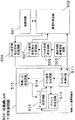
図1に本実施形態における無線通信装置の構成図を示す。この無線通信装置は、通信回路101、通信制御回路102および対無線LAN干渉制御回路103から構成されている。なお、主に対無線LAN干渉制御回路103で、送信要求信号を受信した受信局が受信準備完了信号を返送する第1の無線通信方式を構成する。また、通信回路101および通信制御回路102で、第1の無線通信方式と同一の周波数帯でデータ信号の送受信を行う第2の無線通信方式を構成する。
FIG. 1 shows a configuration diagram of a wireless communication apparatus according to the present embodiment. This wireless communication apparatus includes a
通信回路101は、他の通信装置との間でデータの送受信を行うための回路である。この通信回路101は、自通信システムの通信方式に従い通信装置にアクセスし、伝送信号を送受信する機能を持つ。
The
通信制御回路102は、通信回路101によるデータの送受信を制御するための回路である。この通信制御回路102は、送信データを作成し通信回路101に送信を要求する機能と、通信回路101で受信した受信データの処理を行う機能を持つ。さらに、通信回路101で信号を送信もしくは受信する可能性のある通信期間を対無線LAN干渉制御回路103に通知する機能を持つ。この通信期間は、方式に応じて決定する。例えば、自通信システムが使用する方式として、主局が送信するビーコン信号に同期して通信回路101を間欠動作させる方式を用いている場合は、通信回路101を動作させる時間を通信期間とすることができる。また、単に自通信システムで信号を送信する期間を通信期間としても良いし、他局からのデータ信号を受信する時間を自局の通信内容から予測して通信期間としても良い。
The
対無線LAN干渉制御回路103は、無線LANシステムからの被干渉を回避するための回路である。この対無線LAN干渉制御回路103は、CTSを送信することで無線LANシステムからの被干渉を回避する。対無線LAN干渉制御回路103は具体的には、タイミング制御回路111、デュレーション設定回路112、アドレス設定回路113、CTSフレーム生成回路114、無線LAN送信回路115から構成される。
The anti-wireless LAN interference control circuit 103 is a circuit for avoiding interference from the wireless LAN system. This anti-wireless LAN interference control circuit 103 avoids interference from the wireless LAN system by transmitting CTS. Specifically, the anti-wireless LAN interference control circuit 103 includes a
タイミング制御回路111は、通信期間の長さや送信タイミングを制御するための回路である。このタイミング制御回路111は、通信制御回路102から通知される通信回路101の通信期間に従い、デュレーション設定回路112に次の通信期間の長さを通知し、CTSフレーム生成回路114にCTSフレーム送信タイミングを通知する。具体的には、CSMA/CAに要する可能性のある時間とCTS信号の送信に要する時間と自端末が送信したいデータ量の送信時間とを合わせた時間を、次の通信期間の長さとして通知する。また、この通信時間の長さを考慮して、送信開始時間を早めた期間をCTS送信タイミングとして通知する。
The
デュレーション設定回路112は、タイミング制御回路111および無線LAN送信回路115から通知される通信期間の長さおよび補正情報に基づいてデュレーションを設定するための回路である。即ち、このデュレーション設定回路112は、タイミング制御回路111から通知される上記通信期間の長さおよび無線LAN送信回路115から通知される補正情報に従って、CTSフレームのデュレーションフィールドの値を決定し、その値をCTSフレーム生成回路114に通知する。具体的には、無線LAN送信回路115においてチャンネルアクセスが可能になるまでに要した時間を上記通信期間の長さから引いた時間を、上記CTSフレームのデュレーションフィールドの値として決定し、CTSフレーム生成回路114に通知する。
The
アドレス設定回路113は、CTSフレームのアドレスフィールドを決定し、CTSフレーム生成回路114に通知するための回路である。このアドレス設定回路113によるアドレスフィールドの設定としては、たとえば、自局のアドレスを固定的に設定することができる。
The
CTSフレーム生成回路114は、タイミング制御回路111から通知されたCTS送信タイミングに従い、CTSフレーム信号の送信を無線LAN送信回路115に要求する機能と、デュレーション設定回路112およびアドレス設定回路113から通知された設定値をそれぞれのフィールドに設定したCTSフレームを生成し、無線LAN送信回路115に渡す機能を持つ。
The CTS
無線LAN送信回路115は、CTSフレーム生成回路114からCTSフレーム信号の送信要求が通知されると、CSMA/CA手順に従いチャネルアクセスを試み、チャネルアクセスが可能になった時点で、CSMA/CA手順のためにチャネルアクセスまでに要した時間をデュレーション設定回路112に通知すると共に、CTSフレーム生成回路114からCTSフレームを受け取り、そのCTSを送信する機能を持つ。
When the transmission request for the CTS frame signal is notified from the CTS
[動作]
次に、上記構成の本実施形態に係る無線通信装置の動作を説明する。
[Operation]
Next, the operation of the wireless communication apparatus according to the present embodiment having the above configuration will be described.
本実施形態の無線通信装置は、自通信システムの無線通信装置として、以下のように動作する。 The wireless communication apparatus according to the present embodiment operates as follows as the wireless communication apparatus of its own communication system.
通信回路101は、自通信システムの通信方式に従い、通信装置へのアクセスを制御しており、受信信号を検出すると通信制御回路102に受信データを渡す。通信制御回路102は、通信回路101から渡された受信データを処理し、必要に応じて送信データを生成し通信回路101に送信データの送信を要求する。通信回路101は、通信制御回路102からデータの送信を要求されると、自通信システムの通信方式に従い、データ信号を送信する。
The
この第2の無線通信方式による送受信動作と並行して、無線LANシステムとの干渉を回避するために、第1の無線通信方式による以下の動作を行う。 In parallel with the transmission / reception operation using the second wireless communication system, the following operation using the first wireless communication system is performed in order to avoid interference with the wireless LAN system.
通信制御回路102は、自通信システムの通信方式に従い通信回路101が送信もしくは受信する可能性がある通信期間(上述した通信回路101を動作させる時間等)を求め、対無線LAN干渉制御回路103のタイミング制御回路111に通知する。
The
タイミング制御回路111は、上記通信期間の通知を受けると、CTS送信前に行うCSMA/CAに要する可能性のある時間とCTS信号の送信に要する時間を考慮して、送信開始時間を早めた期間を求め、この期間の長さをデュレーション設定回路112に通知し、この期間の開始時刻をCTS送信タイミングとしてCTSフレーム生成部114に通知する。
When the
CTSフレーム生成部114は、CTSフレーム送信タイミングになると、無線LAN送信回路115にCTSフレームの送信を要求する。無線LAN送信回路115は、CTSフレーム送信要求を受けると、CSMA/CA手順に従いチャネルアクセスを試み、チャネルアクセスが可能になった時点で、それまでに要した時間をデュレーション設定回路112に通知する。
When the CTS frame transmission timing comes, the CTS
デュレーション設定回路112は、上記通知と同時に、タイミング生成回路111から通知された上記期間の長さから、無線LAN通信回路115から通知された上記時間を引いた値をCTSのデュレーションフィールドに設定する値としてCTSフレーム生成回路114に通知する。また、アドレス設定回路113は、常に自アドレスをCTSフレームのアドレスフィールドの値として、CTSフレーム生成回路114に通知している。無線LAN送信回路115は、デュレーションフィールドおよびアドレスフィールドの値が上記の値に設定されたCTSフレームをCTSフレーム生成回路114から受け取り、CTSを送信する。
The
本実施形態の無線通信装置から無線LANの通信範囲内にある無線LAN通信装置は、このCTS信号を受信することにより、そのCTS信号のデュレーションフィールドで示されている期間だけ、信号の送信を禁止するよう動作する。この期間経過後に、自通信装置が通信期間となり、通信回路101による信号の送受信が行われる。
By receiving this CTS signal, the wireless LAN communication device within the wireless LAN communication range of the present embodiment prohibits signal transmission only during the period indicated by the duration field of the CTS signal. To work. After the elapse of this period, the communication apparatus becomes a communication period, and signals are transmitted and received by the
[効果]
以上のように、本発明の第1の実施形態の通信装置では、通信期間の前にCTS信号を送信することにより、自通信装置と無線LANの通信範囲内にある無線LAN通信装置が、自通信装置の通信期間に信号の送信を禁止するように動作するため、自通信装置は無線LAN通信装置からの干渉を被ることなく、通信することができる。
[effect]
As described above, the communication device according to the first embodiment of the present invention transmits a CTS signal before the communication period, so that the wireless LAN communication device within the communication range of the own communication device and the wireless LAN can Since the communication apparatus operates so as to prohibit signal transmission during the communication period, the communication apparatus can communicate without suffering interference from the wireless LAN communication apparatus.
[第2の実施形態]
本実施形態では、無線LANにおける隠れ端末問題を回避するために使用されているRTS/CTS信号を用いて、無線LANシステムからの被干渉を回避できるようにしている。
[Second Embodiment]
In the present embodiment, interference from the wireless LAN system can be avoided by using the RTS / CTS signal that is used to avoid the hidden terminal problem in the wireless LAN.
図4に本発明の第2の実施形態における通信システムの形態を示す。図4に示すように、本実施形態の通信システムは、自通信システムとしての送受信機能に加え、RTSを送信する機能を持つRTS送信局、CTSを送信する機能を持つCTS送信局、RTS送信局およびCTS送信局を指定する管理局、およびその他の自通信システムの機能のみを持つ局で構成している。 FIG. 4 shows a form of a communication system in the second embodiment of the present invention. As shown in FIG. 4, the communication system of the present embodiment includes an RTS transmission station having a function of transmitting RTS, a CTS transmission station having a function of transmitting CTS, and an RTS transmission station in addition to the transmission / reception function of the own communication system. And a management station that designates a CTS transmitting station, and a station that has only the function of its own communication system.
図5に本実施形態におけるRTS送信局の構成図を示す。図中のRTS送信局は、通信回路201、通信制御回路202、対無線LAN干渉制御回路203、RTS送信局指定信号処理回路204、位置情報検出回路205および位置情報データ信号生成回路206から構成されている。
FIG. 5 shows a configuration diagram of the RTS transmitting station in the present embodiment. The RTS transmitting station in the figure includes a
通信回路201は、第1の実施形態の通信装置の通信回路101と同じである。
The
通信制御回路202は、第1の実施形態の通信装置の通信制御回路102の機能に加え、受信データのうち、RTS送信局指定信号、RTS送信局指定解除信号およびCTS送信局指定信号をRTS送信局指定信号処理回路204に渡す機能と、位置情報データ信号生成回路206から受け取った信号を通信回路201に渡し送信させる機能とを持つ。
In addition to the function of the
対無線LAN干渉制御回路203は、タイミング制御回路211、デュレーション設定回路212、アドレス設定回路213、RTSフレーム生成回路214および無線LAN送信回路215から構成されている。このうち、デュレーション設定回路212、無線LAN送信回路215は、第1の実施形態の通信装置のデュレーション設定回路112、無線LAN送信回路115と同じである。
The anti-wireless LAN interference control circuit 203 includes a
タイミング制御回路211は、第1の実施形態の通信装置のタイミング制御回路111とほとんど同じであり、RTS送信局指定信号処理回路204からの指示により動作/停止する点のみが異なる。
The
アドレス設定回路213は、送信局アドレスに自アドレスを、受信局アドレスにCTS送信局に指定された通信局のアドレスを設定するように、RTSフレーム生成回路214に通知する。
The
RTSフレーム生成回路214は、タイミング制御回路211から通知された送信タイミングに従い、RTSフレーム信号の送信を無線LAN送信回路215に要求する機能と、デュレーション設定回路112およびアドレス設定回路213から通知された設定値をそれぞれのフィールドに設定したRTSフレームを生成し、無線LAN送信回路215に渡す機能を持つ。
The RTS
RTS送信局指定信号処理回路204は、タイミング制御回路211の動作/停止を指示する機能を持つ。具体的には、通信制御回路202からRTS送信局指定信号を受け取ると、タイミング制御回路211に動作を指示し、RTS送信局指定解除信号を受け取ると、タイミング制御回路211に停止を指示する。また、通信制御回路202からCTS送信局指定信号を受け取ると、指定されているCTS送信局のアドレスをアドレス設定回路213に通知する。
The RTS transmission station designation
位置情報検出回路205は、通信装置の位置を検出する機能をもち、検出した位置情報を位置情報データ信号生成回路206に通知する。
The position
位置情報データ信号生成回路206は、位置情報検出回路205から通知された位置情報を管理局に通知するためのデータ信号を生成し、通信制御回路202に渡す。
The position information data signal
図6に本実施形態におけるCTS送信局の構成図を示す。図中のCTS送信局は、通信回路301、通信制御回路302、対無線LAN干渉制御回路303、CTS送信局指定信号処理回路304、位置情報検出回路305および位置情報データ信号生成回路306から構成される。
FIG. 6 shows a configuration diagram of the CTS transmitting station in the present embodiment. The CTS transmitting station in the figure includes a
このうち、位置情報検出回路305および位置情報データ信号生成回路306は、上記RTS送信局の位置情報検出回路205および位置情報データ信号生成回路206と同じである。
Among these, the position
通信制御回路302は、第1の実施形態の通信装置の通信制御回路102の機能に加え、受信データのうち、CTS送信局指定信号およびCTS送信局指定解除信号をCTS送信局指定信号処理回路304に渡す機能と、位置情報データ信号生成回路306から受け取った信号を通信回路301に渡し送信させる機能とを持つ。
In addition to the function of the
対無線LAN干渉制御回路303は、無線LAN通信回路311、RTS信号処理回路312およびCTSフレーム生成回路313から構成される。
The anti-wireless LAN interference control circuit 303 includes a wireless
無線LAN通信回路311は、無線LAN信号を送受信する機能をもち、受信した信号をRTS信号処理回路312に渡すと共に、CTSフレーム生成回路313から要求されたCTSフレームを送信する。
The wireless
RTS信号処理回路312は、無線LAN通信回路311から受け取った受信信号がRTS信号である場合に動作し、RTS信号からデュレーションフィールドの値と受信局アドレスの値を抽出し、CTSフレーム生成回路313に通知する機能を持つ。
The RTS
CTSフレーム生成回路313は、RTS信号処理回路312から通知された値に従いCTSフレームを生成し、生成したCTSフレームの送信を無線LAN通信回路311に要求する。
The CTS
CTS送信局指定信号処理回路304は、無線LAN通信回路311の動作/停止を指示する機能を持つ。通信制御回路302からCTS送信局指定信号を受け取ると、無線LAN通信回路311に動作を指示し、CTS送信局指定解除信号を受け取ると、無線LAN通信回路311に停止を指示する。
The CTS transmission station designation
図7に本実施形態における管理局の構成図を示す。図中の管理局は、通信回路401、通信制御回路402、位置情報データ信号処理回路403、位置情報記憶回路404、RTS/CTS送信局選定回路405およびRTS/CTS送信局指定信号生成回路406から構成される。
FIG. 7 shows a configuration diagram of the management station in the present embodiment. The management station in the figure includes a
通信回路401は、第1の実施形態の通信装置の通信回路101と同じである。
The
通信制御回路402は、第1の実施形態の通信装置の通信制御回路102の機能に加え、受信データのうち、位置情報データ信号を位置情報データ信号処理回路403に渡す機能と、RTS/CTS送信局指定信号生成回路406から受け取った信号を通信回路401に渡し送信させる機能とを持つ。
In addition to the function of the
位置情報データ信号処理回路403は、通信制御回路402から位置情報データ信号を受け取ると、その位置情報を送信した通信端末の位置を位置情報記憶回路404に登録する。
When the position information data signal
位置情報記憶回路404は、位置情報データ信号処理回路403から通知される通信端末の位置情報を記憶するための記憶装置である。
The position
RTS/CTS送信局選定回路405は、位置情報記憶回路404に記録されている通信装置の位置情報を基に、RTS送信局およびCTS送信局を選定する機能を持つ。このRTS/CTS送信局選定回路405は、RTS送信局とCTS送信局との距離が長くなるようにRTS送信局およびCTS送信局を選定する。
The RTS / CTS transmission
RTS/CTS送信局指定信号生成回路406は、RTS/CTS送信局選定回路405が選定するRTS送信局もしくはCTS送信局に変更があった場合、変更前のRTS送信局もしくはCTS送信局に対するRTSもしくはCTS送信局指定解除信号および変更後のRTS送信局もしくはCTS送信局に対するRTSもしくはCTS送信局指定信号を生成し、通信制御回路402に渡す。
The RTS / CTS transmission station designation
[動作]
次に、上記構成の通信装置の動作を説明する。
[Operation]
Next, the operation of the communication apparatus having the above configuration will be described.
本実施形態の通信装置における自通信システムの通信装置としての動作は、上記第1の実施形態と同様である。 The operation of the communication apparatus of the present embodiment as the communication apparatus of the own communication system is the same as that of the first embodiment.
この送受信動作と並行して、無線LANシステムとの干渉を回避するために以下の動作を行う。 In parallel with this transmission / reception operation, the following operation is performed in order to avoid interference with the wireless LAN system.
管理局は、システム内の他の通信局から受信した位置情報信号を通信制御回路402が位置情報データ信号処理回路403に渡し、この位置情報データ信号処理回路403で処理して、システム内の通信局の位置情報を位置情報記憶回路404に記録する。
In the management station, the position information signal received from other communication stations in the system is transferred to the position information data signal
次いで、RTS/CTS送信局選定回路405は、位置情報記憶回路404に記録した位置情報に基づいて、RTS送信局とCTS送信局の距離が長くなるように、RTS送信局およびCTS送信局を選定する。RTS/CTS送信局指定信号生成回路406は、RTS/CTS送信局選定回路405で選定したRTS送信局およびCTS送信局に従ってRTS送信局指定信号およびCTS送信局指定信号を生成し、通信制御回路402および通信回路401を介して、RTS送信局指定信号は選定したRTS送信局に、CTS送信局指定信号は選定したRTS送信局およびCTS送信局に、それぞれ送信する。
Next, the RTS / CTS transmission
管理局は、新たに通信局の位置情報を受信すると、位置情報記憶回路404に記録している情報を更新し、RTS/CTS送信局選定回路405で局間の距離がより長くなるRTS送信局とCTS送信局の組がないかを調べる。存在する場合には、RTS送信局および/またはCTS送信局を変更し、RTS/CTS送信局指定信号生成回路406で信号を生成し、次に示すようにして、対応する通信局に送信する。RTS送信局を変更する場合、変更前のRTS送信局に対しRTS送信局指定解除信号を送信し、変更後のRTS送信局に対しRTS送信局指定信号を送信する。CTS送信局を変更する場合、変更前のCTS送信局に対しCTS送信局指定解除信号を送信し、変更後のCTS送信局およびRTS送信局に対しCTS送信局指定信号を送信する。
When the management station newly receives the position information of the communication station, the management station updates the information recorded in the position
管理局からRTS送信局指定信号を受信したRTS送信局では、その信号をRTS送信局指定信号処理回路204で受け取ると、RTS送信局指定信号処理回路204がタイミング制御回路211を動作させる。また、管理局からRTS送信局指定解除信号を受信すると、タイミング制御回路211の動作を停止させる。
In the RTS transmission station that has received the RTS transmission station designation signal from the management station, when the RTS transmission station designation
RTS送信局指定信号を受信したRTS送信局のタイミング制御回路211は、通信制御回路202から通信期間の通知を受けると、CTS送信前に行うCSMA/CAに要する可能性のある時間とCTS信号の送信に要する時間を考慮して、送信開始時間を早めた期間を求め、この期間の長さをデュレーション設定回路212に通知し、この期間の開始時刻をRTS送信タイミングとしてRTSフレーム生成部214に通知する。
Upon receiving the notification of the communication period from the
RTSフレーム生成部214は、RTSフレーム送信タイミングになると、無線LAN送信回路215にRTSフレームの送信を要求する。無線LAN送信回路215は、RTSフレーム送信要求を受けると、CSMA/CA手順に従いチャネルアクセスを試み、チャネルアクセスが可能になった時点で、それまでに要した時間をデュレーション設定回路212に通知する。
The RTS
デュレーション設定回路212は、上記通知と同時に、タイミング生成回路211から通知された期間の長さから、無線LAN通信回路215から通知された時間を引いた時間をRTSのデュレーションフィールドに設定する値としてRTS信号生成回路214に通知する。また、アドレス設定回路213は、送信局アドレスとしてのアドレスと、受信局アドレスとしての、CTS送信局に指定されている通信局のアドレスとを、RTSのアドレスフィールドの値としてRTS信号生成回路214に通知している。RTS信号生成回路214は、これらの値を基にRTS信号を生成して無線LAN通信回路215に渡す。
At the same time as the above notification, the
無線LAN通信回路215は、デュレーションフィールドおよびアドレスフィールドの値が上記の値に設定されたRTSフレームをRTSフレーム生成回路214から受け取り、RTSを送信する。
The wireless
管理局からCTS送信局指定信号を受信したCTS送信局は、CTS送信局指定信号処理回路304の指定に基づいて無線LAN通信回路311を動作させる。また、管理局からCTS送信局指定解除信号を受信すると、無線LAN通信回路311の動作を停止させる。
The CTS transmission station that has received the CTS transmission station designation signal from the management station operates the wireless
CTS送信局指定信号を受信し無線LAN送信回路311を動作させているCTS送信局は、無線LAN通信回路311でRTS信号を受信すると、RTS信号処理回路312でRTS信号からデュレーションフィールドの値と受信局アドレスの値を抽出する。CTSフレーム生成回路313でそれらの値を設定したCTSフレームを生成し、無線LAN通信回路311から送信する。
When the CTS transmitting station that receives the CTS transmitting station designation signal and operates the wireless
上記RTS送信局もしくはCTS送信局から無線LANの通信範囲内にある無線LAN通信装置は、このRTS送信局もしくはCTS送信局からのRTS信号またはCTS信号を受信することにより、デュレーションフィールドで示されている期間、信号の送信を禁止するように動作する。この期間は、干渉の原因になる信号が送信されることがなくなる。これにより、自通信システムでは無線LANからの干渉を被ることなく通信することができる。 The wireless LAN communication device within the wireless LAN communication range from the RTS transmitting station or the CTS transmitting station is indicated by the duration field by receiving the RTS signal or the CTS signal from the RTS transmitting station or the CTS transmitting station. It operates to prohibit signal transmission for a certain period. During this period, signals that cause interference are not transmitted. As a result, the communication system can communicate without suffering interference from the wireless LAN.
[効果]
本発明の第2の実施形態の通信システムでは、通信期間の前にRTS信号およびCTS信号を送信することにより、少なくともRTS信号およびCTS信号のどちらか1つを受信した無線LAN通信装置が、自通信システムの通信期間に信号の送信を禁止するように動作するため、自通信装置は無線LAN通信装置からの干渉を被ることなく通信することができる。
[effect]
In the communication system according to the second embodiment of the present invention, by transmitting the RTS signal and the CTS signal before the communication period, the wireless LAN communication device that has received at least one of the RTS signal and the CTS signal can automatically transmit the RTS signal and the CTS signal. Since it operates so as to prohibit signal transmission during the communication period of the communication system, the own communication device can communicate without suffering interference from the wireless LAN communication device.
特に、できるだけ距離が離れた2つの局からRTS信号およびCTS信号を送信するようにしているため、RTS信号もしくはCTS信号を受信し、無線LAN信号の送信を禁止することのできる範囲が、第1の実施形態の通信装置と比べて広くなり、無線LANシステムからの被干渉をより効率的に抑えることができる。 In particular, since the RTS signal and the CTS signal are transmitted from two stations as far as possible from each other, the range in which the RTS signal or the CTS signal can be received and the transmission of the wireless LAN signal can be prohibited is the first. Compared with the communication apparatus of the embodiment, the interference from the wireless LAN system can be more efficiently suppressed.
[第3の実施形態]
本実施形態の通信システムは、第2の実施形態の通信システムにおいて、管理局が行っていたRTS送信局およびCTS送信局の選定を、RTS送信局およびCTS送信局で自律的に行えるようにしたものである。
[Third embodiment]
In the communication system of the present embodiment, the RTS transmission station and the CTS transmission station that have been performed by the management station in the communication system of the second embodiment can be autonomously selected by the RTS transmission station and the CTS transmission station. Is.
図8に本発明の第3の実施形態に係るRTS送信局の構成図を示す。図中のRTS送信局は、通信回路501、通信制御回路502、対無線LAN干渉制御回路503、RTS送信局指定信号処理回路504、通信局間距離測定回路505、CTS送信局選定回路506およびCTS送信局指定信号生成回路507から構成される。
FIG. 8 shows a configuration diagram of an RTS transmitting station according to the third embodiment of the present invention. The RTS transmitting station in the figure includes a
通信回路501は、第1の実施形態の通信装置の通信回路101と同じである。
The
通信制御回路502は、第1の実施形態の通信装置の通信制御回路102の機能に加え、受信データのうち、RTS送信局指定信号およびRTS送信局指定解除信号をRTS送信局指定信号処理回路504に渡す機能と、CTS送信局指定信号生成回路507から受け取った信号を通信回路501に渡し送信させる機能とを持つ。
In addition to the function of the
対無線LAN干渉制御回路503、RTS送信局指定信号処理回路504は、第2の実施形態のRTS送信局の対無線LAN干渉制御回路203、RTS送信局指定信号処理回路204と同じである。
The anti-wireless LAN interference control circuit 503 and the RTS transmission station designation
通信局間距離測定回路505は、自局と任意の通信局の距離を測定する機能を持つ。この通信局間距離測定回路505は、測定した通信局との距離をCTS送信局選定回路506に通知する。距離の測定は、例えば測定対象の通信局が送信した信号の受信電力の減衰量から推定することができる。距離と減衰量とはほぼ半比例の関係にあるためである。
The inter-communication station distance measuring circuit 505 has a function of measuring the distance between the own station and an arbitrary communication station. This inter-communication station distance measurement circuit 505 notifies the CTS transmission
CTS送信局選定回路506は、通信局間距離測定回路505で測定した距離を基にCTS送信局を選定する。CTS送信局には自局からできるだけ離れた通信局を選定する。つまり、現在指定されているCTS送信局と自局との距離を、新しく測定した通信局との距離と比較し、現在よりも距離が遠い通信局を見つけるとCTS送信局を変更して、CTS送信局指定信号生成回路507に通知する。
The CTS transmission
CTS送信局指定信号生成回路507は、CTS送信局選定回路506が選定するCTS送信局に変更があった場合、変更前のCTS送信局に対するCTS送信局指定解除信号および変更後のCTS送信局に対するCTS送信局指定信号を生成し、通信制御回路502に渡す。
When there is a change in the CTS transmission station selected by the CTS transmission
図9に本発明の第3の実施形態におけるCTS送信局の構成図を示す。図中のCTS送信局は、通信回路601、通信制御回路602、対無線LAN干渉制御回路603、CTS送信局指定信号処理回路604、通信局間距離測定回路605、RTS送信局選定回路606およびRTS送信局指定信号生成回路607から構成される。
FIG. 9 shows a configuration diagram of a CTS transmitting station according to the third embodiment of the present invention. The CTS transmitting station in the figure includes a
通信回路601は、第1の実施形態の通信装置の通信回路101と同じである。
The
通信制御回路602は、第1の実施形態の通信装置の通信制御回路102の機能に加え、受信データのうち、CTS送信局指定信号およびCTS送信局指定解除信号をCTS送信局指定信号処理回路604に渡す機能と、RTS送信局指定信号生成回路607から受け取った信号を通信回路601に渡し送信させる機能とを持つ。
In addition to the function of the
対無線LAN干渉制御回路603、CTS送信局指定信号処理回路604は、第2の実施形態のCTS送信局の対無線LAN干渉制御回路303、CTS送信局指定信号処理回路304と同じである。
The anti-wireless LAN interference control circuit 603 and the CTS transmission station designation
通信局問距離測定回路605は、RTS送信局の通信局間距離測定回路505と同じである。
The communication station
RTS送信局選定回路606は、通信局間距離測定回路605で測定した距離を基にRTS送信局を選定する回路である。RTS送信局には自局からできるだけ離れた通信局を選定する。つまり、現在指定されているRTS送信局よりも距離が遠い通信局を見つけるとRTS送信局を変更する。
The RTS transmission
RTS送信局指定信号生成回路607は、RTS送信局選定回路606が選定するRTS送信局に変更があった場合、変更前のRTS送信局に対するRTS送信局指定解除信号および変更後のRTS送信局に対するRTS送信局指定信号を生成し、通信制御回路602に渡す。
When there is a change in the RTS transmission station selected by the RTS transmission
[動作]
次に、本実施形態の動作を説明する。なお、本実施形態のRTS送信局およびCTS送信局を選定する動作以外は、第2の実施形態の動作と同じであるため、以下では、RTS送信局およびCTS送信局を選定する動作のみを説明する。
[Operation]
Next, the operation of this embodiment will be described. Note that, except for the operation of selecting the RTS transmitting station and the CTS transmitting station of the present embodiment, the operation is the same as that of the second embodiment, and therefore only the operation of selecting the RTS transmitting station and the CTS transmitting station will be described below. To do.
本実施形態の通信システムでは、RTS送信局およびCTS送信局を指定する管理局が存在しない。このため、デフォルトのRTS送信局およびCTS送信局を予め指定しておく。 In the communication system of this embodiment, there is no management station that designates the RTS transmission station and the CTS transmission station. For this reason, a default RTS transmission station and CTS transmission station are designated in advance.
RTS送信局は、新たな通信局を認識すると、通信局間距離測定回路505で自通信局との距離を測定し、CTS送信局選定回路506に通知する。CTS送信局選定回路506は通知された距離が現在のCTS送信局との距離より長い場合、CTS送信局を変更する。CTS送信局が変更されると、CTS送信局指定信号生成回路507は、変更前のCTS送信局に対するCTS送信局指定解除信号および変更後のCTS送信局に対するCTS送信局指定信号を生成し、通信制御回路502を介して送信する。
When the RTS transmitting station recognizes a new communication station, the distance measuring circuit 505 measures the distance from the communication station and notifies the CTS transmitting
CTS送信局は、新たな通信局を認識すると、通信局問距離測定回路605で自通信局との距離を測定し、RTS送信局選定回路606に通知する。RTS送信局選定回路606は通知された距離が現在のRTS送信局との距離より長い場合、RTS送信局を変更する。RTS送信局が変更されると、RTS送信局指定信号生成回路607は、変更前のRTS送信局に対するRTS送信局指定解除信号および変更後のRTS送信局に対するRTS送信局指定信号を生成し、通信制御回路602および通信回路601を介して送信する。
When the CTS transmitting station recognizes a new communication station, the communication station interrogation
以上のようにして、管理局なしで、RTS送信局とCTS送信局の距離が長くなるように、RTS送信局およびCTS送信局が選定される。 As described above, the RTS transmission station and the CTS transmission station are selected so that the distance between the RTS transmission station and the CTS transmission station is increased without the management station.
[効果]
以上のように、本実施形態の通信システムでは、通信システム内に管理局を置かなくても、上記第2に実施形態と同様の効果を得ることができる。
[effect]
As described above, in the communication system of the present embodiment, the same effect as that of the second embodiment can be obtained without placing a management station in the communication system.
[第4の実施形態]
本実施形態の対無線LAN干渉制御装置は、主局が定期的に送信するビーコン信号に同期して通信回路を間欠動作させることができる通信システムの通信領域内に設置し、動作させることにより、無線LANシステムからの被干渉を抑制することができる通信タイミング調整装置である。
[Fourth Embodiment]
The anti-wireless LAN interference control apparatus of the present embodiment is installed and operated in a communication area of a communication system capable of intermittently operating a communication circuit in synchronization with a beacon signal periodically transmitted by a main station. It is a communication timing adjustment device capable of suppressing interference from a wireless LAN system.
図10に本発明の第4の実施形態における対無線LAN干渉制御装置の構成図を示す。図中の対無線LAN干渉制御装置は、受信回路701、通信期間判定回路702および対無線LAN干渉制御回路703から構成される。
FIG. 10 shows a configuration diagram of an anti-wireless LAN interference control apparatus according to the fourth embodiment of the present invention. The anti-wireless LAN interference control apparatus in the figure includes a receiving
対無線LAN干渉制御回路703は、第1の実施形態の通信装置の対無線LAN干渉制御回路103とほぼ同じである。 The wireless LAN interference control circuit 703 is almost the same as the wireless LAN interference control circuit 103 of the communication apparatus according to the first embodiment.
受信回路701は、自通信システムの通信方式に従い、通信装置にアクセスし、伝送信号を受信する機能を持つ。
The receiving
通信期間判定回路702は、自通信システムで通信する可能性のある通信期間を判定し、対無線LAN干渉制御回路703に通知する。
The communication
[動作]
次に、本実施形態の対無線LAN干渉制御装置の動作を説明する。本実施形態の対無線LAN干渉制御回路703の動作は、第1の実施形態の対無線LAN干渉制御回路103の動作とほぼ同じであるため、以下では、対無線LAN干渉制御回路703に通知する通信期間を決定する動作のみ説明する。
[Operation]
Next, the operation of the anti-wireless LAN interference control apparatus of this embodiment will be described. Since the operation of the anti-wireless LAN interference control circuit 703 of this embodiment is almost the same as the operation of the anti-wireless LAN interference control circuit 103 of the first embodiment, hereinafter, the anti-wireless LAN interference control circuit 703 is notified. Only the operation for determining the communication period will be described.
通信期間判定回路702において、受信回路701で受信するビーコン信号との同期を確立し、通信回路の動作期間を検出する。検出した動作期間を自通信システムの通信期間と判定し、対無線LAN干渉制御回路703に通知する。対無線LAN干渉制御回路703は、第1の実施形態の通信装置の対無線LAN干渉制御回路103と同様の動作により、無線LANシステムからの被干渉を回避する。
In the communication
[効果]
上記対無線LAN干渉制御装置では、既存の通信装置で構成されている通信システムの通信領域内に設置することにより、既存の通信装置を改良することなく、通信タイミングの調停を行って無線LAN通信システムからの被干渉を回避することができる。
[effect]
In the above-mentioned wireless LAN interference control apparatus, wireless LAN communication is performed by adjusting the communication timing without improving the existing communication apparatus by being installed in the communication area of the communication system configured by the existing communication apparatus. Interference from the system can be avoided.
[変形例]
第1の実施形態の通信装置および第4の実施形態の対無線LAN干渉制御装置103,703では、CTS信号を送信することにより、無線LAN通信装置の送信を禁止させているが、CTS信号の変わりにRTS信号を送信するようにしても良い。
[Modification]
In the communication apparatus of the first embodiment and the anti-wireless LAN interference control apparatuses 103 and 703 of the fourth embodiment, the transmission of the wireless LAN communication apparatus is prohibited by transmitting the CTS signal. Instead, an RTS signal may be transmitted.
また、第2の実施形態および第3の実施形態において、RTS送信局、CTS送信局および管理局の通信回路および通信制御回路を第4の実施形態の受信回路および通信期間判定回路に置き換えた構成としても良い。 In the second embodiment and the third embodiment, the communication circuit and the communication control circuit of the RTS transmitting station, the CTS transmitting station, and the management station are replaced with the receiving circuit and the communication period determining circuit of the fourth embodiment. It is also good.
第4の実施形態では、デュレーション設定回路712は無線LAN送信回路715からの信号を取り込まずにデュレーション時間を設定するようにしたが、第1の実施形態と同様に、無線LAN送信回路715からの信号を取り込んで補正するようにしてもよいことは言うまでもない。
In the fourth embodiment, the
これらの場合も、上記各実施形態と同様の作用、効果を奏することができる。 In these cases, the same operations and effects as those in the above embodiments can be obtained.
101:通信回路、102:通信制御回路、103:対無線LAN干渉制御回路、111:タイミング制御回路、112:デュレーション設定回路、113:アドレス設定回路、114:CTSフレーム生成回路、115:無線LAN送信回路、201:通信回路、202:通信制御回路、203:対無線LAN干渉制御回路、204:RTS送信局指定信号処理回路、205:位置情報検出回路、206:位置情報データ信号生成回路、211:タイミング制御回路、212:デュレーション設定回路、213:アドレス設定回路、214:RTSフレーム生成回路、215:無線LAN送信回路、301:通信回路、302:通信制御回路、303:対無線LAN干渉制御回路、304:CTS送信局指定信号処理回路、305:位置情報検出回路、306:位置情報データ信号生成回路、311:無線LAN通信回路、312:RTS信号処理回路、313:CTSフレーム生成回路、401:通信回路、402:通信制御回路、403:位置情報データ信号処理回路、404:位置情報記憶回路、405:RTS/CTS送信局選定回路、406:RTS/CTS送信局指定信号生成回路、501:通信回路、502:通信制御回路、503:対無線LAN干渉制御回路、504:RTS送信局指定信号処理回路、505:通信局間距離測定回路、506:CTS送信局選定回路、507:CTS送信局指定信号生成回路、601:通信回路、602:通信制御回路、603:対無線LAN干渉制御回路、604:CTS送信局指定信号処理回路、605:通信局間距離測定回路、606:RTS送信局選定回路、607:RTS送信局指定信号生成回路、701:受信回路、702:通信期間判定回路、703:対無線LAN干渉制御回路。 101: Communication circuit, 102: Communication control circuit, 103: Anti-wireless LAN interference control circuit, 111: Timing control circuit, 112: Duration setting circuit, 113: Address setting circuit, 114: CTS frame generation circuit, 115: Wireless LAN transmission Circuit 201: communication circuit 202: communication control circuit 203: anti-wireless LAN interference control circuit 204: RTS transmission station designation signal processing circuit 205: position information detection circuit 206: position information data signal generation circuit 211: Timing control circuit 212: Duration setting circuit 213: Address setting circuit 214: RTS frame generation circuit 215: Wireless LAN transmission circuit 301: Communication circuit 302: Communication control circuit 303: Anti-wireless LAN interference control circuit 304: CTS transmitting station designation signal processing circuit, 305: Location information Detection circuit, 306: Position information data signal generation circuit, 311: Wireless LAN communication circuit, 312: RTS signal processing circuit, 313: CTS frame generation circuit, 401: Communication circuit, 402: Communication control circuit, 403: Position information data signal Processing circuit 404: Position information storage circuit 405: RTS / CTS transmission station selection circuit 406: RTS / CTS transmission station designation signal generation circuit 501: Communication circuit 502: Communication control circuit 503: Wireless LAN interference control Circuit, 504: RTS transmission station designation signal processing circuit, 505: distance measurement circuit between communication stations, 506: CTS transmission station selection circuit, 507: CTS transmission station designation signal generation circuit, 601: communication circuit, 602: communication control circuit, 603: Anti-wireless LAN interference control circuit, 604: CTS transmission station designation signal processing circuit, 605: Distance measurement between communication stations Circuit, 606: RTS transmitting station selecting circuit, 607: RTS transmitting station specifying signal generating circuit, 701: receiving circuit, 702: communication period determination circuit, 703: wireless-LAN interference control circuit.
Claims (5)
上記第1の無線通信方式の送信要求信号を送信するRTS送信手段と、上記送信要求信号に重畳するデュレーション時間を設定するデュレーション設定手段とを備えて、上記第2の無線通信方式で通信する前に、上記第1の無線通信方式の送信要求信号に上記デュレーション設定手段で設定した上記デュレーション時間を重畳して送信し、
上記第2の無線通信方式で送信要求信号送信の動作/停止を指示する信号を受信することにより上記送信要求信号の送信動作を制御するRTS送信局指定信号処理手段と、
無線通信装置の位置を検出する手段と、
上記第2の無線通信方式で管理機能を持つ無線通信装置に上記手段で検出した位置を通知する手段と
を備えたことを特徴とする無線通信装置。 Before transmitting the data signal, the data signal is transmitted in the same frequency band as the first wireless communication system in which the transmitting station transmits the transmission request signal and the receiving station receiving the transmission request signal returns the reception preparation completion signal. In a wireless communication apparatus that communicates with the second wireless communication method for transmitting and receiving
RTS transmitting means for transmitting a transmission request signal of the first wireless communication system and duration setting means for setting a duration time to be superimposed on the transmission request signal, before communicating by the second wireless communication system To the transmission request signal of the first wireless communication system, the duration time set by the duration setting means is superimposed and transmitted,
RTS transmitting station designation signal processing means for controlling the transmission operation of the transmission request signal by receiving a signal instructing the operation / stop of transmission request signal transmission in the second wireless communication system;
Means for detecting a position of the wireless communication device;
A wireless communication apparatus comprising: means for notifying a position detected by the means to a wireless communication apparatus having a management function in the second wireless communication system.
上記デュレーション設定手段が、上記第2の無線通信方式で上記送信要求信号送信後に通信する時間に、上記第1の無線通信方式で送信要求信号を送信するための前処理に要する可能性のある時間をマージンとして加えた時間をデュレーション時間として設定することを特徴とする無線通信装置。 The wireless communication device according to claim 1,
Time that the duration setting unit may take for pre-processing for transmitting a transmission request signal in the first wireless communication method during the time after the transmission request signal is transmitted in the second wireless communication method A wireless communication apparatus characterized in that a time added as a margin is set as a duration time.
上記RTS送信手段が、上記送信要求信号送信前に、当該信号を送信するための処理にかかった時間を上記デュレーション設定手段に通知する機能を備え、
上記デュレーション設定手段が、上記RTS送信手段から通知された時間に基づいて上記デュレーション時間を補正する機能を備えたことを特徴とする無線通信装置。 The wireless communication device according to claim 2,
The RTS transmitting means has a function of notifying the duration setting means of the time taken for processing to transmit the signal before transmitting the transmission request signal,
The wireless communication apparatus, wherein the duration setting means has a function of correcting the duration time based on the time notified from the RTS transmission means.
上記第1の無線通信方式の信号を送受信する無線通信手段と、
上記第1の無線通信方式で受信した信号の自通信装置宛の送信要求信号からデュレーションフィールドの値と受信局アドレスの値を抽出するRTS信号処理手段と、
当該RTS信号処理手段で抽出した情報を用い受信準備完了信号を生成して第1の無線通信方式で送信するCTS生成手段と、
無線通信装置の位置を検出する手段と、
上記第2の無線通信方式で予め定められた上記無線通信装置に検出した位置を通知する手段と
を備えたことを特徴とする無線通信装置。 Before transmitting the data signal, the data signal is transmitted in the same frequency band as the first wireless communication system in which the transmitting station transmits the transmission request signal and the receiving station receiving the transmission request signal returns the reception preparation completion signal. In a wireless communication apparatus that communicates with the second wireless communication method for transmitting and receiving
Wireless communication means for transmitting and receiving a signal of the first wireless communication method;
RTS signal processing means for extracting the value of the duration field and the value of the receiving station address from the transmission request signal addressed to the own communication device of the signal received by the first wireless communication method;
CTS generation means for generating a reception preparation completion signal using the information extracted by the RTS signal processing means and transmitting it by the first wireless communication method;
Means for detecting a position of the wireless communication device;
A wireless communication apparatus comprising: means for notifying the detected position to the wireless communication apparatus predetermined in the second wireless communication system.
上記第2の無線通信方式で受信準備完了信号返送の動作/停止を指示する信号を受信することにより受信準備完了信号の返送動作を制御するCTS送信局指定信号処理手段を備えたことを特徴とする無線通信装置。 The wireless communication device according to claim 4 ,
CTS transmitting station designation signal processing means for controlling the return operation of the reception preparation completion signal by receiving a signal instructing the operation / stop of the reception preparation completion signal return in the second wireless communication system, Wireless communication device.
Priority Applications (4)
| Application Number | Priority Date | Filing Date | Title |
|---|---|---|---|
| JP2004105778A JP4412033B2 (en) | 2004-03-31 | 2004-03-31 | Wireless communication device |
| CNA2005100527330A CN1677896A (en) | 2004-03-31 | 2005-03-09 | Radio communication device and system and communication timed regulating unit |
| CN201110303828.0A CN102355674B (en) | 2004-03-31 | 2005-03-09 | Wireless communication device, wireless communication system, and communication timing adjustment device |
| US11/080,899 US7363040B2 (en) | 2004-03-31 | 2005-03-16 | Interference avoiding radio transmission unit |
Applications Claiming Priority (1)
| Application Number | Priority Date | Filing Date | Title |
|---|---|---|---|
| JP2004105778A JP4412033B2 (en) | 2004-03-31 | 2004-03-31 | Wireless communication device |
Related Child Applications (1)
| Application Number | Title | Priority Date | Filing Date |
|---|---|---|---|
| JP2009206128A Division JP4862931B2 (en) | 2009-09-07 | 2009-09-07 | Wireless communication device |
Publications (3)
| Publication Number | Publication Date |
|---|---|
| JP2005295107A JP2005295107A (en) | 2005-10-20 |
| JP2005295107A5 JP2005295107A5 (en) | 2007-02-08 |
| JP4412033B2 true JP4412033B2 (en) | 2010-02-10 |
Family
ID=35050228
Family Applications (1)
| Application Number | Title | Priority Date | Filing Date |
|---|---|---|---|
| JP2004105778A Expired - Fee Related JP4412033B2 (en) | 2004-03-31 | 2004-03-31 | Wireless communication device |
Country Status (3)
| Country | Link |
|---|---|
| US (1) | US7363040B2 (en) |
| JP (1) | JP4412033B2 (en) |
| CN (2) | CN1677896A (en) |
Families Citing this family (11)
| Publication number | Priority date | Publication date | Assignee | Title |
|---|---|---|---|---|
| DE10339898B4 (en) * | 2003-08-29 | 2007-03-22 | Siemens Ag | Method for operating a base station of a mobile radio system, signaling unit, control unit, mobile station and computer program |
| JP4536672B2 (en) * | 2006-03-23 | 2010-09-01 | 日本電信電話株式会社 | Radio base station and radio channel update method |
| JP4998280B2 (en) * | 2008-01-16 | 2012-08-15 | ブラザー工業株式会社 | Wireless communication device |
| US8260342B2 (en) * | 2010-01-06 | 2012-09-04 | Anokiwave, Inc. | Communications systems management using MM-wave based motion sensing |
| JP5544573B2 (en) * | 2011-02-10 | 2014-07-09 | 日本電信電話株式会社 | Wireless communication terminal and wireless communication method |
| JP5955627B2 (en) * | 2012-05-02 | 2016-07-20 | シャープ株式会社 | Wireless communication device, wireless communication method, processing device, program |
| US9467275B2 (en) * | 2014-07-18 | 2016-10-11 | Intel Corporation | MAC protocol for full duplex wireless communications |
| US20160183279A1 (en) * | 2014-12-19 | 2016-06-23 | Mediatek Inc. | Time Division Multiplex System and Transmission Method Thereof |
| US10716008B2 (en) | 2016-03-09 | 2020-07-14 | Telefonaktiebolaget Lm Ericsson (Publ) | Methods and nodes for reducing interference in a wireless communications network |
| CN109313414A (en) * | 2016-06-22 | 2019-02-05 | 三菱电机株式会社 | Wireless communication device, wireless site device, apparatus control method and facility control program |
| CN110190871B (en) * | 2019-06-24 | 2021-03-16 | Oppo广东移动通信有限公司 | Method for controlling interference between antennas, electronic device and storage medium |
Family Cites Families (10)
| Publication number | Priority date | Publication date | Assignee | Title |
|---|---|---|---|---|
| JP3629077B2 (en) | 1995-12-08 | 2005-03-16 | 富士通株式会社 | Wireless communication system, base station for wireless communication system, and intermittent power-on type mobile station |
| JP3678967B2 (en) | 2000-02-23 | 2005-08-03 | 日本電信電話株式会社 | Transmission control circuit in digital radio communication system |
| US7054329B2 (en) * | 2000-07-07 | 2006-05-30 | Koninklijke Philips Electronics, N.V. | Collision avoidance in IEEE 802.11 contention free period (CFP) with overlapping basic service sets (BSSs) |
| WO2002037754A2 (en) * | 2000-11-03 | 2002-05-10 | At & T Corp. | Tiered contention multiple access (tcma): a method for priority-based shared channel access |
| AU783921B2 (en) * | 2000-11-16 | 2005-12-22 | Symbol Technologies, Inc. | Coexistence techniques in wireless networks |
| JP3530141B2 (en) * | 2001-03-06 | 2004-05-24 | 松下電器産業株式会社 | Wireless LAN system and wireless LAN system signal collision avoidance method |
| JP2003124938A (en) * | 2001-10-19 | 2003-04-25 | Matsushita Electric Ind Co Ltd | Communication area reserving method and radio communication apparatus used therefor |
| US7342876B2 (en) * | 2001-12-20 | 2008-03-11 | Sri International | Interference mitigation and adaptive routing in wireless ad-hoc packet-switched networks |
| US7184777B2 (en) * | 2002-11-27 | 2007-02-27 | Cognio, Inc. | Server and multiple sensor system for monitoring activity in a shared radio frequency band |
| US7817612B2 (en) * | 2003-07-29 | 2010-10-19 | Sony Corporation | Decentralized wireless communication system, apparatus, and associated methodology |
-
2004
- 2004-03-31 JP JP2004105778A patent/JP4412033B2/en not_active Expired - Fee Related
-
2005
- 2005-03-09 CN CNA2005100527330A patent/CN1677896A/en active Pending
- 2005-03-09 CN CN201110303828.0A patent/CN102355674B/en not_active Expired - Fee Related
- 2005-03-16 US US11/080,899 patent/US7363040B2/en not_active Expired - Fee Related
Also Published As
| Publication number | Publication date |
|---|---|
| CN1677896A (en) | 2005-10-05 |
| CN102355674B (en) | 2015-01-28 |
| US20050233703A1 (en) | 2005-10-20 |
| CN102355674A (en) | 2012-02-15 |
| JP2005295107A (en) | 2005-10-20 |
| US7363040B2 (en) | 2008-04-22 |
Similar Documents
| Publication | Publication Date | Title |
|---|---|---|
| US11785562B2 (en) | Multi-link operation with triggered alignment of frames | |
| US7363040B2 (en) | Interference avoiding radio transmission unit | |
| EP3146777B1 (en) | Unlicensed frequency band with licensed frequency band timing | |
| US6882635B2 (en) | Coexistence between interfering communication systems | |
| KR101481586B1 (en) | Method for communcation time allocation of multiple radio | |
| US9398603B1 (en) | Apparatus to facilitate co-existence of bluetooth and wireless local area networks | |
| CN108476410B (en) | Method and system for radar detection in shared spectrum | |
| US9031009B2 (en) | Transmitting/receiving device, wireless terminal device and wireless communication method for suppression of intra-system interference | |
| JP4742307B2 (en) | Wireless communication device and wireless communication method | |
| KR20090088841A (en) | A serial clear to send(cts) to self(cts2self) messaging processure | |
| JP2007243238A (en) | Relay apparatus, communication terminal and communication system | |
| JP2009267995A (en) | Cognitive wireless communication system, method and device | |
| US20170026819A1 (en) | Out-of-band hidden node detection | |
| JP2004320654A (en) | Communication system, communication device, communication method, and program | |
| US11419149B2 (en) | Systems and methods for latency reduction in backhaul | |
| JP4862931B2 (en) | Wireless communication device | |
| US20080207239A1 (en) | Transmitter apparatus, mobile communication system, base station and communication enable signal transmitter apparatus | |
| JP2005340943A (en) | Radio base station | |
| JP2007006019A (en) | Wireless device, communication station, and wireless network | |
| WO2017043136A1 (en) | Wireless communication device and wireless communication method | |
| US11166311B2 (en) | Systems and methods utilizing channel spatial properties with CSMA | |
| JP4536672B2 (en) | Radio base station and radio channel update method | |
| JP5601113B2 (en) | Wireless communication device | |
| KR100580834B1 (en) | Access method between mobile terminals in Mobile Ad hoc network and mobile terminal therefor | |
| US7330454B2 (en) | Method for reserving communication area and radio communication device used for this method |
Legal Events
| Date | Code | Title | Description |
|---|---|---|---|
| A521 | Request for written amendment filed |
Free format text: JAPANESE INTERMEDIATE CODE: A523 Effective date: 20061219 |
|
| A621 | Written request for application examination |
Free format text: JAPANESE INTERMEDIATE CODE: A621 Effective date: 20061219 |
|
| A977 | Report on retrieval |
Free format text: JAPANESE INTERMEDIATE CODE: A971007 Effective date: 20090216 |
|
| A131 | Notification of reasons for refusal |
Free format text: JAPANESE INTERMEDIATE CODE: A131 Effective date: 20090224 |
|
| A521 | Request for written amendment filed |
Free format text: JAPANESE INTERMEDIATE CODE: A523 Effective date: 20090423 |
|
| A02 | Decision of refusal |
Free format text: JAPANESE INTERMEDIATE CODE: A02 Effective date: 20090609 |
|
| A521 | Request for written amendment filed |
Free format text: JAPANESE INTERMEDIATE CODE: A523 Effective date: 20090907 |
|
| A911 | Transfer to examiner for re-examination before appeal (zenchi) |
Free format text: JAPANESE INTERMEDIATE CODE: A911 Effective date: 20090917 |
|
| TRDD | Decision of grant or rejection written | ||
| A01 | Written decision to grant a patent or to grant a registration (utility model) |
Free format text: JAPANESE INTERMEDIATE CODE: A01 Effective date: 20091027 |
|
| A01 | Written decision to grant a patent or to grant a registration (utility model) |
Free format text: JAPANESE INTERMEDIATE CODE: A01 |
|
| A61 | First payment of annual fees (during grant procedure) |
Free format text: JAPANESE INTERMEDIATE CODE: A61 Effective date: 20091109 |
|
| FPAY | Renewal fee payment (event date is renewal date of database) |
Free format text: PAYMENT UNTIL: 20121127 Year of fee payment: 3 |
|
| R150 | Certificate of patent or registration of utility model |
Free format text: JAPANESE INTERMEDIATE CODE: R150 |
|
| FPAY | Renewal fee payment (event date is renewal date of database) |
Free format text: PAYMENT UNTIL: 20121127 Year of fee payment: 3 |
|
| S531 | Written request for registration of change of domicile |
Free format text: JAPANESE INTERMEDIATE CODE: R313531 |
|
| FPAY | Renewal fee payment (event date is renewal date of database) |
Free format text: PAYMENT UNTIL: 20121127 Year of fee payment: 3 |
|
| R350 | Written notification of registration of transfer |
Free format text: JAPANESE INTERMEDIATE CODE: R350 |
|
| FPAY | Renewal fee payment (event date is renewal date of database) |
Free format text: PAYMENT UNTIL: 20121127 Year of fee payment: 3 |
|
| FPAY | Renewal fee payment (event date is renewal date of database) |
Free format text: PAYMENT UNTIL: 20131127 Year of fee payment: 4 |
|
| LAPS | Cancellation because of no payment of annual fees |