JP2008529669A - Apparatus and method for optical coherence tomography - Google Patents
Apparatus and method for optical coherence tomography Download PDFInfo
- Publication number
- JP2008529669A JP2008529669A JP2007555271A JP2007555271A JP2008529669A JP 2008529669 A JP2008529669 A JP 2008529669A JP 2007555271 A JP2007555271 A JP 2007555271A JP 2007555271 A JP2007555271 A JP 2007555271A JP 2008529669 A JP2008529669 A JP 2008529669A
- Authority
- JP
- Japan
- Prior art keywords
- optical
- imaging probe
- optical fiber
- fiber
- reflector
- Prior art date
- Legal status (The legal status is an assumption and is not a legal conclusion. Google has not performed a legal analysis and makes no representation as to the accuracy of the status listed.)
- Pending
Links
Images


Classifications
-
- G—PHYSICS
- G01—MEASURING; TESTING
- G01B—MEASURING LENGTH, THICKNESS OR SIMILAR LINEAR DIMENSIONS; MEASURING ANGLES; MEASURING AREAS; MEASURING IRREGULARITIES OF SURFACES OR CONTOURS
- G01B9/00—Measuring instruments characterised by the use of optical techniques
- G01B9/02—Interferometers
- G01B9/0209—Low-coherence interferometers
- G01B9/02091—Tomographic interferometers, e.g. based on optical coherence
-
- A—HUMAN NECESSITIES
- A61—MEDICAL OR VETERINARY SCIENCE; HYGIENE
- A61B—DIAGNOSIS; SURGERY; IDENTIFICATION
- A61B5/00—Measuring for diagnostic purposes; Identification of persons
- A61B5/0059—Measuring for diagnostic purposes; Identification of persons using light, e.g. diagnosis by transillumination, diascopy, fluorescence
- A61B5/0062—Arrangements for scanning
- A61B5/0066—Optical coherence imaging
-
- A—HUMAN NECESSITIES
- A61—MEDICAL OR VETERINARY SCIENCE; HYGIENE
- A61B—DIAGNOSIS; SURGERY; IDENTIFICATION
- A61B5/00—Measuring for diagnostic purposes; Identification of persons
- A61B5/68—Arrangements of detecting, measuring or recording means, e.g. sensors, in relation to patient
- A61B5/6846—Arrangements of detecting, measuring or recording means, e.g. sensors, in relation to patient specially adapted to be brought in contact with an internal body part, i.e. invasive
- A61B5/6847—Arrangements of detecting, measuring or recording means, e.g. sensors, in relation to patient specially adapted to be brought in contact with an internal body part, i.e. invasive mounted on an invasive device
- A61B5/6852—Catheters
-
- G—PHYSICS
- G01—MEASURING; TESTING
- G01B—MEASURING LENGTH, THICKNESS OR SIMILAR LINEAR DIMENSIONS; MEASURING ANGLES; MEASURING AREAS; MEASURING IRREGULARITIES OF SURFACES OR CONTOURS
- G01B9/00—Measuring instruments characterised by the use of optical techniques
- G01B9/02—Interferometers
- G01B9/02049—Interferometers characterised by particular mechanical design details
- G01B9/0205—Interferometers characterised by particular mechanical design details of probe head
-
- G—PHYSICS
- G01—MEASURING; TESTING
- G01N—INVESTIGATING OR ANALYSING MATERIALS BY DETERMINING THEIR CHEMICAL OR PHYSICAL PROPERTIES
- G01N21/00—Investigating or analysing materials by the use of optical means, i.e. using sub-millimetre waves, infrared, visible or ultraviolet light
- G01N21/17—Systems in which incident light is modified in accordance with the properties of the material investigated
- G01N21/47—Scattering, i.e. diffuse reflection
- G01N21/4738—Diffuse reflection, e.g. also for testing fluids, fibrous materials
- G01N21/474—Details of optical heads therefor, e.g. using optical fibres
-
- G—PHYSICS
- G01—MEASURING; TESTING
- G01N—INVESTIGATING OR ANALYSING MATERIALS BY DETERMINING THEIR CHEMICAL OR PHYSICAL PROPERTIES
- G01N21/00—Investigating or analysing materials by the use of optical means, i.e. using sub-millimetre waves, infrared, visible or ultraviolet light
- G01N21/17—Systems in which incident light is modified in accordance with the properties of the material investigated
- G01N21/47—Scattering, i.e. diffuse reflection
- G01N21/4795—Scattering, i.e. diffuse reflection spatially resolved investigating of object in scattering medium
-
- G—PHYSICS
- G01—MEASURING; TESTING
- G01N—INVESTIGATING OR ANALYSING MATERIALS BY DETERMINING THEIR CHEMICAL OR PHYSICAL PROPERTIES
- G01N21/00—Investigating or analysing materials by the use of optical means, i.e. using sub-millimetre waves, infrared, visible or ultraviolet light
- G01N21/84—Systems specially adapted for particular applications
- G01N21/85—Investigating moving fluids or granular solids
- G01N21/8507—Probe photometers, i.e. with optical measuring part dipped into fluid sample
-
- G—PHYSICS
- G02—OPTICS
- G02B—OPTICAL ELEMENTS, SYSTEMS OR APPARATUS
- G02B6/00—Light guides; Structural details of arrangements comprising light guides and other optical elements, e.g. couplings
- G02B6/24—Coupling light guides
- G02B6/26—Optical coupling means
- G02B6/262—Optical details of coupling light into, or out of, or between fibre ends, e.g. special fibre end shapes or associated optical elements
-
- G—PHYSICS
- G01—MEASURING; TESTING
- G01B—MEASURING LENGTH, THICKNESS OR SIMILAR LINEAR DIMENSIONS; MEASURING ANGLES; MEASURING AREAS; MEASURING IRREGULARITIES OF SURFACES OR CONTOURS
- G01B2290/00—Aspects of interferometers not specifically covered by any group under G01B9/02
- G01B2290/65—Spatial scanning object beam
-
- G—PHYSICS
- G01—MEASURING; TESTING
- G01B—MEASURING LENGTH, THICKNESS OR SIMILAR LINEAR DIMENSIONS; MEASURING ANGLES; MEASURING AREAS; MEASURING IRREGULARITIES OF SURFACES OR CONTOURS
- G01B2290/00—Aspects of interferometers not specifically covered by any group under G01B9/02
- G01B2290/70—Using polarization in the interferometer
-
- G—PHYSICS
- G01—MEASURING; TESTING
- G01N—INVESTIGATING OR ANALYSING MATERIALS BY DETERMINING THEIR CHEMICAL OR PHYSICAL PROPERTIES
- G01N21/00—Investigating or analysing materials by the use of optical means, i.e. using sub-millimetre waves, infrared, visible or ultraviolet light
- G01N21/17—Systems in which incident light is modified in accordance with the properties of the material investigated
- G01N2021/178—Methods for obtaining spatial resolution of the property being measured
- G01N2021/1785—Three dimensional
- G01N2021/1787—Tomographic, i.e. computerised reconstruction from projective measurements
-
- G—PHYSICS
- G01—MEASURING; TESTING
- G01N—INVESTIGATING OR ANALYSING MATERIALS BY DETERMINING THEIR CHEMICAL OR PHYSICAL PROPERTIES
- G01N21/00—Investigating or analysing materials by the use of optical means, i.e. using sub-millimetre waves, infrared, visible or ultraviolet light
- G01N21/84—Systems specially adapted for particular applications
- G01N21/85—Investigating moving fluids or granular solids
- G01N21/8507—Probe photometers, i.e. with optical measuring part dipped into fluid sample
- G01N2021/8514—Probe photometers, i.e. with optical measuring part dipped into fluid sample with immersed mirror
-
- G—PHYSICS
- G01—MEASURING; TESTING
- G01N—INVESTIGATING OR ANALYSING MATERIALS BY DETERMINING THEIR CHEMICAL OR PHYSICAL PROPERTIES
- G01N21/00—Investigating or analysing materials by the use of optical means, i.e. using sub-millimetre waves, infrared, visible or ultraviolet light
- G01N21/84—Systems specially adapted for particular applications
- G01N21/85—Investigating moving fluids or granular solids
- G01N21/8507—Probe photometers, i.e. with optical measuring part dipped into fluid sample
- G01N2021/8528—Immerged light conductor
Landscapes
- Health & Medical Sciences (AREA)
- Physics & Mathematics (AREA)
- Life Sciences & Earth Sciences (AREA)
- General Health & Medical Sciences (AREA)
- General Physics & Mathematics (AREA)
- Pathology (AREA)
- Immunology (AREA)
- Chemical & Material Sciences (AREA)
- Analytical Chemistry (AREA)
- Biochemistry (AREA)
- Biophysics (AREA)
- Molecular Biology (AREA)
- Nuclear Medicine, Radiotherapy & Molecular Imaging (AREA)
- Engineering & Computer Science (AREA)
- Biomedical Technology (AREA)
- Heart & Thoracic Surgery (AREA)
- Medical Informatics (AREA)
- Radiology & Medical Imaging (AREA)
- Surgery (AREA)
- Animal Behavior & Ethology (AREA)
- Public Health (AREA)
- Veterinary Medicine (AREA)
- Optics & Photonics (AREA)
- Investigating Or Analysing Materials By Optical Means (AREA)
- Endoscopes (AREA)
Abstract
一特徴として本発明は撮影プローブに関連している。撮影プローブは近位端と遠位端とを有する細長体を含み、細長体はスライド可能な光ファイバの一部を取り囲むように構成されており、光ファイバは長手方向軸を有しさらにファイバの遠位端には第1の光学アセンブリが取り付けられている。第1の光学アセンブリはファイバから放射された光を長手方向軸に対して所定角度に設定された面に向けるように構成されたビーム偏向器を含んでおり、細長体の近位部にはリニアアクチュエータが設置されており、アクチュエータは細長体と光ファイバとの間の相対的なリニア運動を生じさせるように構成されており、細長体の遠位部には第2の光学アセンブリが配置されているとともにそこに取り付けられており、第2の光学アセンブリは第1の光学アセンブリと光学的に連通した反射器を備えており、反射器は細長体よりも遠位側へ光を向けるように構成されている。 In one aspect, the invention relates to an imaging probe. The imaging probe includes an elongate body having a proximal end and a distal end, the elongate body configured to surround a portion of the slidable optical fiber, the optical fiber having a longitudinal axis and further comprising a fiber. A first optical assembly is attached to the distal end. The first optical assembly includes a beam deflector configured to direct light emitted from the fiber to a plane set at a predetermined angle with respect to the longitudinal axis, with a linear portion at the proximal portion of the elongated body. An actuator is installed, the actuator is configured to produce a relative linear motion between the elongated body and the optical fiber, and a second optical assembly is disposed at the distal portion of the elongated body. And the second optical assembly includes a reflector in optical communication with the first optical assembly, the reflector configured to direct light distally of the elongated body Has been.
Description
本発明は、光学的撮影の分野に関し、詳しくは光学コヒーレンス断層撮影法(OCT)や他の光学的撮影技術における光ファイバプローブの構造に関する。 The present invention relates to the field of optical imaging, and more particularly to the structure of an optical fiber probe in optical coherence tomography (OCT) and other optical imaging techniques.
低侵襲的な医療診断や治療に対する需要が高まるにつれて、顕微鏡スケールで生体組織を検査するための技術がますます重要となっている。約1mmから1cmを越える範囲の直径を有する従来の医療用内視鏡により、医者が胃腸、肺及び生殖器官の内腔壁表面を視認することが可能となっている。しかしながら、癌やその他の病態に関連する病巣を見つけたり特定したりする上では、組織の表面下を見ることが不可欠である。干渉計の画像化技術である光学コヒーレンス断層撮影法(OCT)は、径の小さいプローブとカテーテルによる生体組織の表面下の可視化にとって理想的に適合している。 As the demand for minimally invasive medical diagnosis and treatment increases, techniques for examining biological tissue on a microscopic scale are becoming increasingly important. Conventional medical endoscopes having diameters ranging from about 1 mm to over 1 cm allow a physician to view the luminal wall surfaces of the gastrointestinal tract, lungs, and reproductive organs. However, to find and identify lesions associated with cancer and other pathologies, it is essential to look under the surface of the tissue. Optical coherence tomography (OCT), an imaging technique for interferometers, is ideally suited for subsurface visualization of living tissue with small diameter probes and catheters.
既存のOCT走査方法では、主として検流計を用いて、目的物体を線状に横切るようにプローブビームを走査する。また、既存のシステムでは、回転モータを用いて、円形横断面を有する管腔の内周に沿ってプローブビームを走査する。いずれの方法も、狭い開口を通してプローブ前方の目的物を見るという要求を満たさない。そのため、閉塞した冠動脈の可視化を可能とするプローブに対する特定のニーズが存在する。その目的は、プラークの構造を特定すること、及び閉塞箇所の分析用又は除去用に設計されたアテローム切除術装置をガイドすることである。また、オペレータが針の前進移動に伴って組織構造を視認できる針挿入用OCTプローブに対するニーズが存在する。さらに、前方撮影用内視鏡のワーキングチャネルを通して挿入が可能なプローブに対するニーズが存在する。 In the existing OCT scanning method, a probe beam is scanned so as to cross a target object in a line shape mainly using a galvanometer. In existing systems, a rotary motor is used to scan the probe beam along the inner circumference of a lumen having a circular cross section. Neither method meets the requirement of viewing the object in front of the probe through a narrow aperture. Therefore, there is a specific need for probes that allow visualization of occluded coronary arteries. Its purpose is to identify the structure of the plaque and to guide an atherectomy device designed for analysis or removal of the obstruction site. There is also a need for an OCT probe for needle insertion that allows an operator to visually recognize the tissue structure as the needle moves forward. Furthermore, there is a need for a probe that can be inserted through the working channel of a front imaging endoscope.
これらニーズを実現することは、前方光学走査の可能性を考慮する限り、多くの場合において現実的でない。この理由は以下の通りである。つまり、これらを実施すると、解析困難な非線形の走査パターンが生成されたり、複雑かつ高価な構造が必要となったり、径の大き過ぎるプローブが必要となったりするためである。さらに、ファイバ内視鏡の遠位端やその付近にアクチュエータや可動機構が配置されたシステムは、遠位端をできる限り小さくしようとする要望に対して矛盾したものとなる。それ故、必要とされているのは、プローブの遠位部が従来技術に比して大幅に小型化かつ簡素化したような、遠位部での前方走査が可能なカテーテル構造である。 Realizing these needs is not practical in many cases as long as the possibility of forward optical scanning is considered. The reason is as follows. That is, if these are implemented, a nonlinear scanning pattern that is difficult to analyze is generated, a complicated and expensive structure is required, or a probe having an excessively large diameter is required. Furthermore, a system in which an actuator or a movable mechanism is disposed at or near the distal end of the fiber endoscope contradicts the desire to make the distal end as small as possible. Therefore, what is needed is a catheter structure that allows forward scanning at the distal portion, such that the distal portion of the probe is much smaller and simpler than the prior art.
本発明は、小径かつ前方向きのプローブを用いて、生体組織や他の物体の撮影を行うための方法や装置に関するものである。ここで開示する方法は、従来方法での限界を有利に克服するプッシュプルアクチュエータの仕組みを基礎としている。特に、ここで開示されたプローブの構造やそれに関連する作動方法は、カテーテルを通して前方撮影を行うことを可能とするものであるが、このカテーテルの径は、冠状動脈内や、小口径の注射針内や、及び/又は小型内視鏡のワーキングチャネル内に配置するのに十分に小さく形成されている。 The present invention relates to a method and an apparatus for photographing living tissue and other objects using a probe having a small diameter and facing forward. The method disclosed herein is based on a push-pull actuator mechanism that advantageously overcomes the limitations of conventional methods. In particular, the structure of the probe disclosed herein and the operation method associated therewith enable anterior imaging through the catheter, and the diameter of the catheter is within the coronary artery or a small-diameter injection needle. It is formed small enough to be placed inside and / or within the working channel of a small endoscope.
一特徴として、本発明は、マイクロレンズとビーム偏向器とが一体化されたシングルモード光ファイバを有する撮影プローブに関するものであり、この光ファイバは柔軟性を有する透明チューブ内で長手方向に前後移動する。側方走査ビームは、固定プリズム又は固定ミラーにより方向転換され、カテーテルの先端前方にある物体の横断面OCT走査を行う。 As one feature, the present invention relates to an imaging probe having a single mode optical fiber in which a microlens and a beam deflector are integrated, and this optical fiber moves back and forth in the longitudinal direction in a flexible transparent tube. To do. The side scanning beam is redirected by a fixed prism or fixed mirror to perform a cross-sectional OCT scan of the object in front of the tip of the catheter.
他の特徴として、本発明は、斜め研磨加工が施されたシングルモード光ファイバを有するプローブに関するものであり、この光ファイバは、ミラーと固定レンズアセンブリとが取り付けられた柔軟性を有する透明チューブ内で長手方向に前後移動する。前記レンズアセンブリは、チューブ先端に配置され、チューブ前方の目的物にビームを集束させて断面OCT走査を行う。 As another feature, the present invention relates to a probe having a single-mode optical fiber subjected to oblique polishing, and the optical fiber is in a flexible transparent tube to which a mirror and a fixed lens assembly are attached. To move back and forth in the longitudinal direction. The lens assembly is disposed at the distal end of the tube, and performs cross-sectional OCT scanning by focusing the beam on an object in front of the tube.
一特徴として、本発明は、撮影プローブに関するものである。当該撮影プローブは、近位端と遠位端とを有する細長体を有する。当該細長体は、スライド可能な光ファイバの一部を囲むように構成されており、当該光ファイバは長手方向軸を有しており、当該ファイバの遠位端には第1の光学アセンブリが取り付けられている。当該第1の光学アセンブリは、前記ファイバから放射された光を、前記長手方向軸に対して所定角度に設定された面に向けるように構成されたビーム偏向器を有している。前記細長体の近位部にはリニアアクチュエータが設置されており、当該アクチュエータは前記細長体と前記光ファイバとの間の相対的なリニア運動を生じさせるように構成されている。さらにまた、前記細長体の遠位部には第2の光学アセンブリが配置されているとともにそこに取り付けられており、当該第2の光学アセンブリは前記第1の光学アセンブリと光学的に連通した反射器を有しており、その反射器は前記細長体よりも遠位側へ光を向けるように構成されている。 As one feature, the present invention relates to an imaging probe. The imaging probe has an elongated body having a proximal end and a distal end. The elongate body is configured to enclose a portion of a slidable optical fiber, the optical fiber having a longitudinal axis, and a first optical assembly attached to the distal end of the fiber. It has been. The first optical assembly includes a beam deflector configured to direct light emitted from the fiber to a plane set at a predetermined angle with respect to the longitudinal axis. A linear actuator is installed at a proximal portion of the elongated body, and the actuator is configured to cause a relative linear motion between the elongated body and the optical fiber. Furthermore, a second optical assembly is disposed on and attached to the distal portion of the elongated body, the second optical assembly being in reflective communication with the first optical assembly. And the reflector is configured to direct light distally of the elongate body.
本発明の特徴について様々な形態及び実施が存在する。例えば、前記反射器の位置を、前記相対的なリニア運動に対応して前記光が前方視方向において走査を行うように構成してもよい。前記プローブは前記細長体を概ね取り囲む固定コアをさらに含んだものとしてもよく、当該固定コアは当該固定コアの回転に対応してカテーテル先端の撮影位置が変化するように構成されている。前記第1の光学アセンブリはさらに、当該光ファイバ先端に配置された集束マイクロレンズと、前記細長体内に設置され、走査ビームの前方の視野角及び距離を大幅に適正化する角度に傾斜された単一の反射器と、を含むようにしてもよく、これらレンズ及び反射器は、前記細長体の前記遠位端よりも遠位側に配置され、かつ前記ファイバの前記長手方向軸に対して概ね直交とされた撮影面を形成するものである。前記反射器と光学的窓は、前記細長体に取り付けられた透明の光学材料のブロックにより構成されたものとしてもよい。 There are various forms and implementations of the features of the present invention. For example, the position of the reflector may be configured such that the light scans in the forward viewing direction corresponding to the relative linear motion. The probe may further include a fixed core that generally surrounds the elongated body, and the fixed core is configured such that the imaging position of the catheter tip changes in response to the rotation of the fixed core. The first optical assembly further includes a focusing microlens disposed at the tip of the optical fiber and a single unit disposed within the elongated body and inclined to an angle that greatly optimizes the viewing angle and distance in front of the scanning beam. A reflector, the lens and the reflector being disposed distal to the distal end of the elongate body and generally orthogonal to the longitudinal axis of the fiber. The formed photographing surface is formed. The reflector and the optical window may be constituted by a block of transparent optical material attached to the elongated body.
加えて、前記第1の光学アセンブリが、斜め研磨加工が施された先端を有する光ファイバを備えており、前記第2の光学アセンブリが、前記細長体の外側に取り付けられたハウジング内に対のマイクロレンズを有する前記反射器を備えている構成としてもよい。前記レンズの焦点距離及び位置が、所望の焦点サイズ及び作動距離を実現するように選択されるようにしてもよい。前記光学アセンブリは、斜め研磨加工が施された先端を有する光ファイバと、前記細長体の外側に取り付けられたハウジング内に単一の屈折率分布型レンズを有する反射器と、を含んだものとしてもよく、前記屈折率分布型レンズの屈折率プロファイル及び位置は、所望の焦点サイズ及び作動距離を実現するように選択されている。前記リニアアクチュエータがボイスコイルを含んでいてもよい。 In addition, the first optical assembly includes an optical fiber having a tip subjected to oblique polishing, and the second optical assembly is paired in a housing attached to the outside of the elongated body. It is good also as a structure provided with the said reflector which has a microlens. The focal length and position of the lens may be selected to achieve a desired focal size and working distance. The optical assembly includes an optical fiber having a tip subjected to oblique polishing, and a reflector having a single gradient index lens in a housing attached to the outside of the elongated body. Alternatively, the refractive index profile and position of the gradient index lens are selected to achieve the desired focal spot size and working distance. The linear actuator may include a voice coil.
さらにまた、他の一形態として、前記リニアアクチュエータは、前記ファイバを当該アクチュエータに対して固定状態としながら前記シースを移動させるように構成されている。前記細長体が、流体で満たされているとともに、前記光ファイバの周りで前後に移動するように構成されていてもよい。前記プローブは、光が放射される先端を除き前記光ファイバを概ね覆う金属チューブと、当該金属チューブ及び前記光ファイバに対して移動するように構成され、流体で満たされた外側シースと、をさらに含んだものとしてもよい。他の一形態として、前記プローブは、生物組織走査の関連用途において、光学コヒーレンス断層撮影法システムのサンプルアーム系で用いられるように構成されていてもよい。 Furthermore, as another embodiment, the linear actuator is configured to move the sheath while fixing the fiber to the actuator. The elongate body may be configured to be filled with a fluid and to move back and forth around the optical fiber. The probe further includes a metal tube that generally covers the optical fiber except for a tip from which light is emitted, and an outer sheath that is configured to move relative to the metal tube and the optical fiber and is filled with a fluid. It may be included. As another form, the probe may be configured to be used in a sample arm system of an optical coherence tomography system in related applications of biological tissue scanning.
光学コヒーレンス断層撮影法システムにおけるリファレンスアーム系又はサンプルアーム系のいずれか一方には光路長調整手段が含まれていてもよく、当該手段はアクチュエータ走査により誘発される光路長の変化を自動的に補正するものである。前記ビームは、前記アクチュエータの前記リニア運動に同期して線状に走査するものであってもよい。前記細長体は、湾曲した先端をさらに含んだものとしてもよく、少なくとも当該先端の一部は前記リニア運動に応じて光を放射するように構成されている。 Either the reference arm system or the sample arm system in the optical coherence tomography system may include an optical path length adjusting means, which automatically corrects the optical path length change induced by the actuator scanning. To do. The beam may be scanned linearly in synchronization with the linear motion of the actuator. The elongated body may further include a curved tip, and at least a part of the tip is configured to emit light according to the linear motion.
他の特徴として、本発明は光学コヒーレンス断層撮影法の前方走査システムに関連している。このシステムは、リニアアクチュエータと、当該リニアアクチュエータと機械的に接続され、傾斜端面を有するシングルモードの光ファイバと、前記反射器に対する前記光ファイバ端面の動作により、前記光ファイバ端面からの光が当該光ファイバの円形横断面に対して概ね平行な面に向けられる角度に設置された反射器を有するシースと、を含んでいる。当該システムは、光ファイバの回転ひずみ緩和装置をさらに含んだものとしてもよく、当該装置は前記ファイバと機械的に連結されている。 In another aspect, the invention relates to an optical coherence tomography forward scanning system. The system includes a linear actuator, a single-mode optical fiber that is mechanically connected to the linear actuator and has an inclined end surface, and the operation of the optical fiber end surface with respect to the reflector. And a sheath having a reflector disposed at an angle directed to a plane generally parallel to the circular cross section of the optical fiber. The system may further include an optical fiber rotational strain relief device that is mechanically coupled to the fiber.
他の特徴として、本発明は光ファイバの回転ひずみ緩和装置に関連している。この装置は、第1のポートと第2のポートとを有するチューブを含んでおり、当該チューブは少なくとも一のループ部を形成するように構成されており、さらに前記第1のポートは光学コヒーレンス断層撮影法の撮影プローブと接続するように構成されており、前記チューブの内部は光ファイバのスライドを容易なものとするように構成されている。前記第2のポートを干渉計のサンプルアーム系と接続するように構成してもよい。前記ループ部を概ね円形のものとしてもよい。 In another aspect, the invention relates to an optical fiber rotational strain relief device. The apparatus includes a tube having a first port and a second port, wherein the tube is configured to form at least one loop, and the first port is an optical coherence tomography. The tube is configured to be connected to an imaging probe for imaging, and the inside of the tube is configured to facilitate sliding of the optical fiber. The second port may be configured to be connected to a sample arm system of the interferometer. The loop portion may be substantially circular.
上記特徴における形態は、血管内部や小さな体腔内部の画像ガイダンスによる利益を享受するアテローム切除術、前立腺切除術及び他の臨床診断法のために設計された治療用機器に適していることが重要な特徴である。 It is important that the features in the above features be suitable for therapeutic devices designed for atherectomy, prostatectomy and other clinical diagnostic methods that benefit from image guidance inside blood vessels and small body cavities. It is a feature.
本発明の他の特徴としては、露出組織の表面の撮影に適していることであり、一体化したマイクロレンズ・ビーム偏向器を有するシングルモードの光ファイバを含んでおり、その光ファイバは透明性を有するプラスチックチューブ内において長手方向の前後に移動する。当該チューブの先端はU字に形成されており、ビームは当該先端の底面において下方に向けられる。前記光ファイバの長手方向の移動により前方線走査が行われる。 Another feature of the present invention is that it is suitable for imaging exposed tissue surfaces and includes a single mode optical fiber having an integrated microlens beam deflector, the optical fiber being transparent. It moves back and forth in the longitudinal direction in a plastic tube having The tip of the tube is U-shaped, and the beam is directed downward on the bottom surface of the tip. A forward line scan is performed by moving the optical fiber in the longitudinal direction.
本発明のさらなる特徴は、プローブと駆動機構との加工方法を含んでいることであり、この方法により、走査ビームの方向、振幅及び繰り返し率の制御が可能となる。 A further feature of the present invention is that it includes a processing method of the probe and the drive mechanism, which enables control of the direction, amplitude and repetition rate of the scanning beam.
「ある」、「本」、「その」、「この」といった語は、特に限定する場合を除き、「一つ又は複数」であることを意味する。 The words “a”, “book”, “the” and “this” mean “one or more” unless otherwise specified.
本発明自体のみならず、本発明の上記特徴及び利点、あるいは他の特徴及び利点は、明細書、図面及び請求の範囲からより完全に理解される。 The above features and advantages of the invention, as well as other features and advantages, as well as the invention itself, will be more fully understood from the specification, drawings and claims.
特許請求の範囲に記載された発明は、下記の詳細な説明を、添付の図面と併せて読むことにより完全に理解される。この詳細な説明では、本発明の種々の形態における同様の部位には同様の符号が付されている。 The invention as set forth in the claims is fully understood when the following detailed description is read in conjunction with the accompanying drawings. In this detailed description, similar parts in the various embodiments of the present invention are provided with the same reference numerals.
以下の記述は、本発明の実施形態を表す添付図面を参照する。他の実施形態も可能であり、また本実施形態に本発明の精神及び範囲から逸脱しない変更を加えることもできる。したがって、以下の詳細な記述は本発明を限定するものではない。本発明の範囲は、むしろ添付の請求の範囲によって決められる。 The following description refers to the accompanying drawings that represent embodiments of the present invention. Other embodiments are possible, and modifications can be made to the embodiments without departing from the spirit and scope of the invention. Accordingly, the following detailed description does not limit the invention. The scope of the invention is rather determined by the appended claims.
本発明の方法における工程の順序は、本発明の効果を奏する限り重視されるものではないことが了解される。また、別の順序が特定されていなければ、2以上の工程を同時に実施することや、ここで示された順序と異なる順序で実施することも可能である。 It is understood that the order of the steps in the method of the present invention is not important as long as the effects of the present invention are exhibited. If another order is not specified, two or more steps can be performed simultaneously or in an order different from the order shown here.
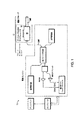
ここで開示されている本発明の特徴及び形態は、概して、撮影システムの構成部品に関連している。特に、本発明の一特徴は、光学コヒーレンス断層撮影法、蛍光法、ラマン分光法、又は他のタイプの光学的な検出方法に基づく撮影システムの使用に適した構成部品を含み、その構成部品として、例えばプローブ、プッシュプル装置、アクチュエータ、コイル、機械的接続部品その他部品が挙げられる。一例として、図1に、OCTシステム10を示す。このOCTシステム10は、プッシュプル装置及び他の好適な構成部品によって作動する前方走査光ファイバプローブを適用するために設計されたものである。
The features and forms of the invention disclosed herein generally relate to the components of an imaging system. In particular, one aspect of the present invention includes components suitable for use in imaging systems based on optical coherence tomography, fluorescence, Raman spectroscopy, or other types of optical detection methods, such as Examples include probes, push-pull devices, actuators, coils, mechanical connection parts, and other parts. As an example, FIG. 1 shows an
図1に示すように、広帯域光源が発する光は、光ファイバ干渉計によってリファレンスビームとサンプルビームとに分割される。走査の軸方向成分を生成するために、光学遅延線がリファレンスアーム系の光路長を変化させる。リファレンスビーム及びサンプルビームの干渉は、直交する2つの偏光経路を介して検出される。各経路において生成された干渉信号を組合せて、サンプルビーム系の偏光変化を感知しないようにすることができる。あるいは、これら信号を個別に処理し、サンプルビームの偏光性質に関する情報を抽出することができる。 As shown in FIG. 1, the light emitted from the broadband light source is divided into a reference beam and a sample beam by an optical fiber interferometer. An optical delay line changes the optical path length of the reference arm system to generate the axial component of the scan. The interference of the reference beam and the sample beam is detected via two orthogonal polarization paths. The interference signals generated in each path can be combined so as not to sense polarization changes in the sample beam system. Alternatively, these signals can be processed individually to extract information about the polarization properties of the sample beam.
一特徴として、本発明は、サブシステム12とその部分とに関し、これらはサンプルアーム系との接続に適したプッシュプル式アクチュエータと撮影プローブとを含む。また、アクチュエータ及びプローブは、共働して走査の横軸方向成分を生成する。ここで示すように、サブシステム12には、前記干渉計から延出するシングルモードファイバSMFが収容されている。このシングルモードファイバSMFは、細長体14内においてスライド自在に配置され、撮影プローブの一部分を形成している。他の形態では、シングルモードファイバSMFは、金属チューブのような耐久性スリーブに覆われ、及び/又は、固着されている。さらに、細長体に対してシングルモードファイバをスライド自在に作動させるプッシュプルアクチュエータ16が示されている。前記サブシステムでは、近位での機械的動作が可能とされ、またカテーテル先端が小型に維持されている。ビーム偏向器や他の光学アセンブリは、典型的に、シングルモード光ファイバの遠位端に取り付けられている。プッシュプル式前方走査撮影プローブの基本的概念に関し、図2を参照して更に詳しく述べる。
In one aspect, the present invention relates to subsystem 12 and parts thereof, which include a push-pull actuator and imaging probe suitable for connection to a sample arm system. In addition, the actuator and the probe work together to generate a horizontal direction component of scanning. As shown here, the
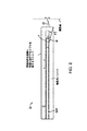
図2では、プローブ部20が細長体21を備えていることが示されている。この細長体21は、例えば管腔やチューブであり、サンプルビームを送受光するのに適した光ファイバSMFを収容している。矢印によって細長体に対してスライド自在な方向が示されているように、光ファイバが細長体21内にスライド可能に配置されている。ファイバ先端は、当該ファイバの側面から集束ビーム22が放射されるように、所定の角度(一般的に約40から約45度)に研磨加工が施されている。研磨加工が施されたファイバの先端といったような、一体化した集光レンズL・ビーム偏向器を有する光ファイバは、この用途において特に好都合である。他の一特徴では、本発明は、一体化した集光マイクロレンズ・ビーム偏向器を有するシングルモードの光ファイバを備えており、この光ファイバは、柔軟性を有する透明チューブ内において長手方向の前後に移動する。前記側面からの走査ビームは、カテーテル先端の前方にある物体に対し横断面OCT走査を行うために、固定プリズムM又は固定ミラーMによって放射方向が転換される。
In FIG. 2, it is shown that the
ビーム22は、角度α(一般的に約40から約45度)に傾斜されたミラーによって、ファイバの長手方向軸に沿って前方に向けられる。シース(細長体)が前記ファイバに対して長手方向に一定速度で移動することにより、前記ビームが前方の画像面上を均一に線状に走査する。前記光ファイバが平行移動する際に前記チューブを固定しておくか、又は前記チューブが平行移動する際に前記光ファイバを固定しておくかのいずれかによって、相対的な動作が行われる。後者の方法は、以下の詳述において明確にされるように、機械的利点を有する。前記チューブ21をシースに対して移動させる方が好ましいのは、この構成により、オペレータは、プッシュプル動作を阻害することなく、近位端から前記ファイバを回転させて、走査の方位角面の調整を行うことができるためである。α=45°では、画像面までのサンプルビームの光路長は走査中一定であり、また、画像面における走査長は前記チューブが前記ファイバに対して平行移動する直線距離と等しい。
Beam 22 is directed forward along the longitudinal axis of the fiber by a mirror tilted at an angle α (typically about 40 to about 45 degrees). As the sheath (elongated body) moves at a constant speed in the longitudinal direction with respect to the fiber, the beam scans the front image surface uniformly in a linear manner. Relative operation is performed by either fixing the tube when the optical fiber is translated or by fixing the optical fiber when the tube is translated. The latter method has mechanical advantages, as will be clarified in the following detailed description. It is preferable to move the
実質的に前方走査が可能となるように、一般的に、画像面はカテーテルの末端よりも遠位側に配置される。例えば、カテーテルの一部やシースの一部のような細長体を、閉塞箇所を有する動脈内に配置する場合、細長体が動脈に到達すれば、閉塞箇所の前方走査が可能となる。このような例では、画像面の一部又は全体を閉塞箇所に設定することができる。 In general, the image plane is located distal to the end of the catheter so that a substantially forward scan is possible. For example, when an elongated body such as a part of a catheter or a part of a sheath is placed in an artery having an occlusion site, forward scanning of the occlusion site is possible when the elongate body reaches the artery. In such an example, a part or the whole of the image plane can be set as a blockage location.
図2に示すサイドミラーMを単純かつ安価に製造する方法は、光ファイバを短く切断し、先端に斜め研磨加工及びコーティングを施して、光ファイバSMFの外側を平行移動するチューブ内に挿入することである。α=45°において、有効な走査長は、前記サイドミラーを製造する上で用いられるファイバの直径と概ね等しい。他の一形態では、プローブに用いられる光ファイバは、細長体の内側に、スライド可能かつ回転可能に設置されている。このように、本発明は、一特徴として、関連制御、振動低減、及び光学的損失の減少を伴いつつ、リニア運動から前方光学走査への転換を可能とする。 A simple and inexpensive method of manufacturing the side mirror M shown in FIG. 2 is to cut an optical fiber into short pieces, obliquely polish and coat the tip, and insert the outside of the optical fiber SMF into a tube that translates. It is. At α = 45 °, the effective scan length is approximately equal to the diameter of the fiber used to manufacture the side mirror. In another embodiment, the optical fiber used for the probe is slidably and rotatably installed inside the elongated body. Thus, the present invention, as one feature, allows a transition from linear motion to forward optical scanning with associated control, vibration reduction, and optical loss reduction.
図2のプローブ20で示されている基本的概念のアレンジとして、様々な形態が可能である。図3のプローブ部30に示すように、傾きαの角度を45°未満に設定してもよく、これによりプローブが占める横断面領域をより効果的に活用することができる。αの減少に伴って、画像面における走査線は、プローブの長手方向軸に近付いていく。図3の記載によれば、画像面における走査距離と長手軸方向の平行移動距離との関係は、d’=dtanαとして与えられる。α≠0°では、以下の数式に示すように、画像面までのサンプルビームの光路長は、走査距離に対して線形変化する。
Various forms of arrangement of the basic concept shown by the
![]()
![]()
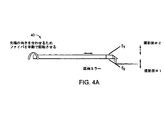
図4Aは、図2にて示した概念の拡張例を表すファイバ部40を示している。図4Bは、プローブの一形態の端面図を示している。このシステムでは、3つのミラーの区画面S1,S2,S3がコーナー・キューブ装置構成に配列されており、オペレータは、ファイバを回転させることにより、画像面の3つの異なる方位角面のうち1つを選択することができる。ファイバは、ミラーアセンブリの中央に設けられた孔45を貫通している。特定用途に対する要求に応じて、区画面数が異なるミラーを用いてもよい。区画ミラーを構成するために、様々な方法を用いることができる。例えば、斜め研磨加工及びコーティングが施された短い光ファイバから成るミラーを複数個、光ファイバの外側を平行移動するチューブ壁内に挿入してもよい。また、ミラー面を、プラスチック又はセラミックのブロックで成形し、金属の反射材で覆うようにしてもよい。アセンブリを簡略化するために、プッシュプル式プローブの先端は、ミラーアセンブリと別個のユニットとして構成されている。シースで覆われたファイバが前記ミラーに対して平行移動することによって、前方面での走査長がオペレータによって手動で調整される。
FIG. 4A shows a
図5A〜図7は、上記した前方走査を行うプッシュプル式プローブの他の実施形態を示す。図5A〜図5Bにおいて、プローブ例50では、ガラス又は透明樹脂でできた硬質ロッド52の遠位端の平坦領域51を研磨することによって、傾斜ミラーが形成されている。平坦領域51は、内部全反射によってビームを偏向させるためコーティングを施さなくてもよいし、表面汚れに対する感度を低減するため誘電体又は金属でコーティングを施してもよい。一体化したレンズ・ビーム偏向器を備えた光ファイバ54の先端は、ロッド52に開けられた孔に挿入されている。機械加工を小寸法で行う必要性を抑えるために、アセンブリ全体をガラス又はプラスチックにより形成してもよい。後者のプラスチックによる製造方法は、使い捨てプローブの大量生産に有用である。
5A to 7 show another embodiment of the push-pull probe that performs the forward scanning described above. 5A to 5B, in the probe example 50, the inclined mirror is formed by polishing the
他の用途、特に長い動作距離でプローブビームの焦点をしっかりと合わせるという要望に対しては、光ファイバの先端に一体化されたレンズ・ビーム偏向器に代えて、外付けレンズアセンブリを用いてもよい。図6は、光学窓62を備えたレンズアセンブリ61を有するプローブ部60の一例を示す。この形態では、斜め研磨加工が施されたファイバの側面から発散光が放射され、その光が外付けミラーで反射され、対の平凸レンズ又は非球面レンズを通過する。これらレンズはプローブ前方の特定距離にビームの焦点を合わせるものである。また、これらレンズは焦点面上にファイバのコアの像を写すため、その焦点サイズはd0f1/f2に比例している。ここで、d0はファイバのコアの直径であり、f1/f2はレンズの焦点距離の比である。したがって、所望の焦点距離を有するレンズを選択することで、プローブの方位分解能を設定することができる。他の形態として、焦点サイズが約5μmから約40μmの範囲となるように、かつ作動距離が約0.5cmから約5cmの範囲となるように、前記レンズを選択してもよい。あるいは、簡易な構成とするために、図7に示す他のプローブ例70のように、平凸レンズに類似した光学特性を有する屈折率分布型(GRIN)レンズを採用してもよい。
For other applications, particularly the desire to focus the probe beam tightly over long working distances, an external lens assembly can be used instead of a lens and beam deflector integrated at the tip of the optical fiber. Good. FIG. 6 shows an example of a
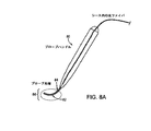
図8A〜図8Bは、前方走査用ビームを発生させる他のシステムを示す。このシステムは手で持って操作できるプローブとして有用である。この形態では、平行移動するファイバコアを収容したチューブ84に、湾曲部82が形成されている。このチューブはプローブ先端部86の形に適合し、チューブの底面全体にはビームが放射される溝が形成されている。このプローブは、体表から到達できる臓器や狭い切開箇所を通じて到達できる臓器を撮影するために設計されている。例えば、低侵襲手術中に、外科医師の視界を遮ることなく、プローブ先端部86を対象領域近くに配置することができる。内視鏡的な用途では、ハンドル部分を取り外してもよく、またプローブビームが通るチューブ領域に可撓性を持たせてもよい。このような変更により、内視鏡のワーキングチャネルへ挿入するために、プローブを真直ぐに伸ばすことが可能となる。予め型付けられた先端により、撮影プローブが内視鏡から出たときも、撮影プローブは組織の傍に留まることができ、内視鏡が湾曲する必要がない。
8A-8B show another system for generating a forward scanning beam. This system is useful as a probe that can be operated by hand. In this embodiment, a
図9は、プッシュプル式の機械的接続部品を用いる2つのシステム90aと90bを表している。この機械的接続部品は、前方走査プローブ(図5〜図8)の様々な形態において用いることが可能である。システム90aと90bは、共通の‘ルアー’部91を備えている。O―リングアセンブリ92を有するT型接続具も示されている。システム90bでは、光ファイバを有する熱接着シースアセンブリ93が、チューブ部94と連通している。
FIG. 9 shows two
また、図10では、ここで示されたプッシュプル式撮影プローブを組み込むのに適した他のシステム100が示されている。接続部品は光ファイバを備えており、この光ファイバは可撓性金属(ニチノール又は巻ステンレス)チューブに挿入されている。このチューブは、流体で満たされた透明プラスチックのシース内を、長手方向にスライドする。シースPSの近位端は、ボイスコイルアクチュエータ101のコアによって駆動される(図10)。具体的には、ボイスコイルアクチュエータ101が振動プローブマウント103を作動させることによって撮影プローブが駆動し、それによりシース102が振動する。プローブコネクタ及び/又はローテタ104は、典型的には、シース102と機械的に連通している。シース102及びファイバを概ね取り囲む撮影プローブの固定コア105も示されている。ルアーアダプタ(登録商標)91’も図10に示されている。
Also shown in FIG. 10 is another
他の形態として、固定コア105は、撮影部位やカテーテル先端の光路を変更するために手動で回転されるものであってもよい。線形変化作動変圧器のような位置フィードバック装置106もまた、システム100に具備されてもよい。振動ダンパ107とセンタリングバネ108を組み込むようにしてもよい。さらに、光ファイバ回転ひずみ緩和ループ109が示されている。このループ109は、第1ポートを介して撮影プローブと連結するように構成されている。加えて、このループは、第2ポートを介して干渉計のサンプルビーム系と連結するように構成されている。このループはまた、光ファイバをスライド可能に収容するように構成されている。その光ファイバは、シース内を通って、対象管腔内へ挿入されたり対象標本近くへ配置されたりするための撮影プローブ内に伸びている。
As another form, the fixed
光ファイバをシースに対して平行移動させるために、ファイバではなくシースに対してプッシュプル動作を行う。これは、後述するように顕著な有利点を有している。通常、シース自体の中間部は、メイン内視鏡、針状プローブ、主カテーテル、又はシースが挿入される生体入口部によって支持される。このため、シースの近位端を押してファイバの近位端から離隔させると、ファイバの遠位端が、撮影対象の管腔内や組織内に存在する遠位側のシース内部に引込まれる。こうして、ファイバの遠位端が撮影対象の組織に対して平行移動して走査を行っている間、近位部は固定された状態となる。ファイバは、力の伝達を一定に維持するために、チューブの近位端及び遠位端の両方に接着されている。流体は、光ファイバの遠位端とシースとの潤滑性を提供するとともに、両者の光学的な連通状態を向上させる。ボイスコイルアクチュエータは、位置センサからのフィードバック制御により、移動速度を一定に維持する。 In order to translate the optical fiber relative to the sheath, a push-pull operation is performed on the sheath, not the fiber. This has significant advantages as will be described later. Usually, the intermediate part of the sheath itself is supported by a main endoscope, a needle probe, a main catheter, or a living body inlet part into which the sheath is inserted. For this reason, when the proximal end of the sheath is pushed away from the proximal end of the fiber, the distal end of the fiber is drawn into the distal sheath existing in the lumen or tissue of the imaging target. Thus, while the distal end of the fiber moves in parallel with the tissue to be imaged for scanning, the proximal portion remains fixed. The fiber is glued to both the proximal and distal ends of the tube to keep force transmission constant. The fluid provides lubricity between the distal end of the optical fiber and the sheath and improves the optical communication between the two. The voice coil actuator keeps the moving speed constant by feedback control from the position sensor.
他の形態として、図9及び図10の形態は、走査距離(一般的に数ミリメートルから1センチメートル)全長に亘って光ファイバが円滑に平行移動するように設計されている。平行移動の繰返し率は、動きアーチファクトを回避するのに十分に高い率に設定されている。ボイスコイルの各サイクルにおける動作は、双方向電気信号によって制御されるが、この信号は、線形変化差動変圧器、光学エンコーダ、又は同様のタイプのセンサによる位置フィードバックにより、ボイスコイルに適用されるものである。往復運動の両端位置でコイルの向きを反転するのに要する作動電流を減少させるため、対向する一対のバネがボイスコイルのシャフトに連結されている。(オプションの)ダッシュポット又は同様の装置が、振動を防ぐために機械の作用を緩和する。高精度の位置制御がそれほど要求されない用途では、バネ復帰力を利用する一方向電子駆動装置(ソレノイド)を採用してもよい。 As another form, the form of FIG.9 and FIG.10 is designed so that an optical fiber may translate smoothly over the scanning distance (generally several millimeters-1 centimeter) full length. The repetition rate of translation is set high enough to avoid motion artifacts. The operation of each cycle of the voice coil is controlled by a bi-directional electrical signal that is applied to the voice coil by position feedback by a linear change differential transformer, optical encoder, or similar type of sensor. Is. A pair of opposing springs are connected to the shaft of the voice coil in order to reduce the operating current required to reverse the direction of the coil at both ends of the reciprocating motion. An (optional) dashpot or similar device mitigates the action of the machine to prevent vibrations. In applications where high-accuracy position control is not so required, a one-way electronic drive device (solenoid) that uses a spring return force may be employed.
プッシュプル式プローブの遠位端にあるミラーの方向を合わせるために、便利な手段(部材104)が典型的に設けられており、この手段は、光ファイバがシースに対して平行移動するのに干渉することなく、光ファイバを回転させるものである。図9及び図10で示されたプッシュプル式接続部品の近位端の構造は、この目的を達成するものである。そこで示すように、ファイバは、シースの長手方向のどの位置においても回転可能であり、これがファイバではなくシースを移動させる利点である。プッシュプル動作のサイクル中は、ファイバの長手方向位置が固定されているので、光ファイバコネクタ96はオペレータの操作による回転のみを必要とし、前後運動を要しない。図10では、その光ファイバコネクタ(図示せず)は、部材91’と104との間に配置されている。この構造は、撮影システムとの連結を容易化するだけでなく、プッシュプル動作のサイクル中にリニアアクチュエータから伝達される荷重のばらつきを減少させる。その光ファイバは、手動でもサーボ制御モータでも、回転することができる。
In order to orient the mirror at the distal end of the push-pull probe, a convenient means (member 104) is typically provided to allow the optical fiber to translate relative to the sheath. The optical fiber is rotated without interference. The structure at the proximal end of the push-pull connection piece shown in FIGS. 9 and 10 accomplishes this purpose. As shown there, the fiber can rotate at any position in the longitudinal direction of the sheath, which is an advantage of moving the sheath rather than the fiber. Since the longitudinal position of the fiber is fixed during the push-pull operation cycle, the
請求の範囲に記載された発明の様々な特徴は、ここで開示された技術の一部又は一工程を対象としていることが理解される。さらに、ここで採用された語句及び表現は、説明のために用いられるものであり、限定のために用いられるものではない。また、これら語句及び表現の使用においては、ここで示され記述された特徴及びその部分と均等のものを除外する意図はない。しかしながら、請求の範囲に記載された発明の範囲内での種々の変更は可能であることが理解される。したがって、特許証により保護が要求される範囲は、請求の範囲において定められかつ明確にされた発明及びその全ての均等物である。 It is understood that the various features of the claimed invention are directed to a part or one step of the technology disclosed herein. Further, the phrases and expressions adopted here are used for explanation and not for limitation. Moreover, the use of these phrases and expressions is not intended to exclude the features shown and described herein and their equivalents. However, it will be understood that various modifications may be made within the scope of the claimed invention. Accordingly, the scope of protection required by a patent certificate is the invention as defined and defined in the claims and all equivalents thereof.
以下に示す図面や請求の範囲を参照することで、本発明の目的及び特徴がよりよく理解される。図面は、必ずしも基準となるものでもなく、重要視されるものでもなく、本発明の本質を説明するために添付されている。示された図面が、その開示の範囲内で個々の原理を扱っていれば、その図面は開示と関連するものである。 The objects and features of the invention can be better understood with reference to the following drawings and claims. The drawings are not necessarily to be regarded as normative and are attached to illustrate the nature of the invention. If the drawings shown deal with individual principles within the scope of the disclosure, the drawings are relevant to the disclosure.
Claims (21)
近位端と遠位端とを有した細長体を備え、当該細長体はスライド可能な光ファイバの一部を取り囲むように構成され、当該光ファイバは長手方向軸を有しており、
当該ファイバの遠位端に取り付けられた第1の光学アセンブリをさらに備え、当該第1の光学アセンブリは前記ファイバから放射された光を、前記長手方向軸に対して所定角度に設定された面に向けるように構成されたビーム偏向器を有しており、
前記細長体の近位部に配置されたリニアアクチュエータをさらに備え、当該アクチュエータは前記細長体と前記光ファイバとの間の相対的なリニア運動を生じさせるように構成されており、
前記細長体の遠位部に配置されているとともにそこに取り付けられた第2の光学アセンブリをさらに備え、当該第2の光学アセンブリは前記第1の光学アセンブリと光学的に連通した反射器を有しており、当該反射器は前記細長体よりも遠位側へ光を向けるように構成されていることを特徴とする撮影プローブ。 An imaging probe,
An elongate body having a proximal end and a distal end, the elongate body configured to surround a portion of the slidable optical fiber, the optical fiber having a longitudinal axis;
A first optical assembly attached to the distal end of the fiber, the first optical assembly directing light emitted from the fiber to a plane set at a predetermined angle with respect to the longitudinal axis; A beam deflector configured to direct,
A linear actuator disposed at a proximal portion of the elongate body, the actuator configured to cause relative linear motion between the elongate body and the optical fiber;
The apparatus further comprises a second optical assembly disposed at and attached to a distal portion of the elongated body, the second optical assembly having a reflector in optical communication with the first optical assembly. The imaging probe is characterized in that the reflector is configured to direct light toward the distal side of the elongated body.
これらレンズ及び反射器は、前記細長体の前記遠位端よりも遠位側に配置され、かつ前記ファイバの前記長手方向軸に対して概ね直交とされた撮影面を形成することを特徴とする請求項1に記載の撮影プローブ。 The first optical assembly further includes a focusing microlens disposed at the tip of the optical fiber and a single unit disposed within the elongated body and tilted to an angle that greatly optimizes the forward viewing angle and distance of the scanning beam. A reflector, and
These lenses and reflectors are disposed distal to the distal end of the elongate body and form an imaging surface that is generally orthogonal to the longitudinal axis of the fiber. The imaging probe according to claim 1.
前記屈折率分布型レンズの屈折率プロファイル及び位置は、所望の焦点サイズ及び作動距離を実現するように選択されていることを特徴とする請求項1に記載の撮影プローブ。 The optical assembly includes an optical fiber having a tip subjected to an oblique polishing process, and a reflector having a single gradient index lens in a housing attached to the elongate body,
The imaging probe according to claim 1, wherein the refractive index profile and position of the gradient index lens are selected to achieve a desired focal spot size and working distance.
当該リニアアクチュエータに機械的に接続され、傾斜端面を有するシングルモード光ファイバと、
前記反射器に対する前記光ファイバ端面の動作により、前記光ファイバ端面からの光が光ファイバの円形横断面に対し概ね平行な面に向けられる角度に設置された反射器を有するシースと、
を備えていることを特徴とする光学コヒーレンス断層撮影法の前方走査システム。 A linear actuator;
A single mode optical fiber mechanically connected to the linear actuator and having an inclined end face;
A sheath having a reflector placed at an angle such that light from the end face of the optical fiber is directed to a plane generally parallel to the circular cross section of the optical fiber by operation of the end face of the optical fiber relative to the reflector;
A forward scanning system for optical coherence tomography.
第1のポートと第2のポートとを有するチューブを備えており、当該チューブは少なくとも一のループ部を形成するように構成されており、
前記第1のポートは光学コヒーレンス断層撮影法の撮影プローブと接続するように構成されており、前記チューブ内部は光ファイバのスライドを容易なものとするように構成されていることを特徴とする光ファイバの回転ひずみ緩和装置。 A rotational strain relief device,
A tube having a first port and a second port, the tube being configured to form at least one loop;
The first port is configured to be connected to an imaging probe for optical coherence tomography, and the inside of the tube is configured to facilitate sliding of an optical fiber. Fiber rotational strain relief.
Applications Claiming Priority (2)
| Application Number | Priority Date | Filing Date | Title |
|---|---|---|---|
| US65183105P | 2005-02-10 | 2005-02-10 | |
| PCT/US2006/004863 WO2006086700A2 (en) | 2005-02-10 | 2006-02-10 | Optical coherence tomography apparatus and methods |
Publications (2)
| Publication Number | Publication Date |
|---|---|
| JP2008529669A true JP2008529669A (en) | 2008-08-07 |
| JP2008529669A5 JP2008529669A5 (en) | 2009-03-26 |
Family
ID=36499165
Family Applications (1)
| Application Number | Title | Priority Date | Filing Date |
|---|---|---|---|
| JP2007555271A Pending JP2008529669A (en) | 2005-02-10 | 2006-02-10 | Apparatus and method for optical coherence tomography |
Country Status (4)
| Country | Link |
|---|---|
| US (1) | US7848791B2 (en) |
| EP (1) | EP1850735A2 (en) |
| JP (1) | JP2008529669A (en) |
| WO (1) | WO2006086700A2 (en) |
Cited By (1)
| Publication number | Priority date | Publication date | Assignee | Title |
|---|---|---|---|---|
| JP2012509729A (en) * | 2008-11-26 | 2012-04-26 | カール ツァイス サージカル ゲーエムベーハー | Imaging system |
Families Citing this family (167)
| Publication number | Priority date | Publication date | Assignee | Title |
|---|---|---|---|---|
| US7241286B2 (en) * | 2003-04-25 | 2007-07-10 | Lightlab Imaging, Llc | Flush catheter with flow directing sheath |
| US20080009844A1 (en) * | 2006-06-26 | 2008-01-10 | Ingeborg Rolle | Device for Laser Surgery |
| US9867530B2 (en) | 2006-08-14 | 2018-01-16 | Volcano Corporation | Telescopic side port catheter device with imaging system and method for accessing side branch occlusions |
| FR2904927B1 (en) * | 2006-08-17 | 2018-05-18 | Mauna Kea Technologies | USE OF A FIBER IN VIVO IN SITU CONFOCAL FLUORESCENCE IMAGING SYSTEM, SYSTEM AND METHOD FOR CONFOCAL FIBER IN VIVO IN SITU FLUORESCENCE IMAGING |
| US20080097223A1 (en) * | 2006-10-20 | 2008-04-24 | Infraredx, Inc. | Optical Catheter Carriage Interlock System and Method |
| US20080097158A1 (en) * | 2006-10-20 | 2008-04-24 | Infraredx, Inc. | Noise Suppression System and Method in Catheter Pullback and Rotation System |
| US20080097224A1 (en) * | 2006-10-20 | 2008-04-24 | Infraredx, Inc. | Manual and Motor Driven Optical Pullback and Rotation System and Method |
| US20080097408A1 (en) * | 2006-10-20 | 2008-04-24 | Infraredx, Inc. | Pullback Carriage Interlock System and Method for Catheter System |
| EP2628443B1 (en) | 2006-11-08 | 2021-05-12 | Lightlab Imaging, Inc. | Opto-acoustic imaging device |
| JP5543212B2 (en) * | 2006-11-21 | 2014-07-09 | コーニンクレッカ フィリップス エヌ ヴェ | System for imaging prostate cancer, method of operating system for imaging prostate cancer, and computer-readable medium |
| CN105581776B (en) | 2007-01-10 | 2018-10-16 | 光学实验室成像公司 | Device and method and linearisation tunable optic filter for tunable optic filter linearisation |
| JP5524835B2 (en) * | 2007-07-12 | 2014-06-18 | ヴォルカノ コーポレイション | In vivo imaging catheter |
| US9596993B2 (en) | 2007-07-12 | 2017-03-21 | Volcano Corporation | Automatic calibration systems and methods of use |
| WO2009009802A1 (en) | 2007-07-12 | 2009-01-15 | Volcano Corporation | Oct-ivus catheter for concurrent luminal imaging |
| US7682089B2 (en) * | 2007-08-15 | 2010-03-23 | Rohlen Brooks H | System and method for positioning a probe |
| US8582934B2 (en) | 2007-11-12 | 2013-11-12 | Lightlab Imaging, Inc. | Miniature optical elements for fiber-optic beam shaping |
| US7813609B2 (en) * | 2007-11-12 | 2010-10-12 | Lightlab Imaging, Inc. | Imaging catheter with integrated reference reflector |
| US9498600B2 (en) | 2009-07-01 | 2016-11-22 | Avinger, Inc. | Atherectomy catheter with laterally-displaceable tip |
| US8062316B2 (en) | 2008-04-23 | 2011-11-22 | Avinger, Inc. | Catheter system and method for boring through blocked vascular passages |
| US9125562B2 (en) | 2009-07-01 | 2015-09-08 | Avinger, Inc. | Catheter-based off-axis optical coherence tomography imaging system |
| ES2517915T3 (en) * | 2008-06-02 | 2014-11-04 | Lightlab Imaging, Inc. | Quantitative methods to obtain characteristics of a tissue from optical coherence tomography images |
| DE102008045634A1 (en) | 2008-09-03 | 2010-03-04 | Ludwig-Maximilians-Universität München | Wavelength tunable light source |
| EP2344020B1 (en) | 2008-10-14 | 2020-05-20 | Lightlab Imaging, Inc. | Stent strut detection and related measurement and display using optical coherence tomography |
| EP2226003B1 (en) * | 2009-03-05 | 2015-05-06 | Brainlab AG | Medical image registration by means of optical coherence tomography |
| WO2010129075A1 (en) | 2009-04-28 | 2010-11-11 | Avinger, Inc. | Guidewire support catheter |
| EP4145111A1 (en) | 2009-05-28 | 2023-03-08 | Avinger, Inc. | Optical coherence tomography for biological imaging |
| US8670129B2 (en) | 2009-09-03 | 2014-03-11 | Axsun Technologies, Inc. | Filtered ASE swept source for OCT medical imaging |
| US8526472B2 (en) | 2009-09-03 | 2013-09-03 | Axsun Technologies, Inc. | ASE swept source with self-tracking filter for OCT medical imaging |
| US8412312B2 (en) * | 2009-09-23 | 2013-04-02 | Lightlab Imaging, Inc. | Apparatus, systems, and methods of in-vivo blood clearing in a lumen |
| EP2480124B1 (en) * | 2009-09-23 | 2017-11-22 | Lightlab Imaging, Inc. | Lumen morphology and vascular resistance measurement data collection systems, apparatus and methods |
| WO2011072068A2 (en) | 2009-12-08 | 2011-06-16 | Avinger, Inc. | Devices and methods for predicting and preventing restenosis |
| US8926590B2 (en) | 2009-12-22 | 2015-01-06 | Lightlab Imaging, Inc. | Torque limiter for an OCT catheter |
| US8206377B2 (en) * | 2009-12-22 | 2012-06-26 | Lightlab Imaging, Inc. | Torque limiter for an OCT catheter |
| US8478384B2 (en) | 2010-01-19 | 2013-07-02 | Lightlab Imaging, Inc. | Intravascular optical coherence tomography system with pressure monitoring interface and accessories |
| AU2011227178B2 (en) * | 2010-03-17 | 2013-11-07 | Lightlab Imaging, Inc. | Intensity noise reduction methods and apparatus for interferometric sensing and imaging systems |
| US8259304B2 (en) | 2010-05-26 | 2012-09-04 | Gerard A Alphonse | Broadband discrete spectrum optical source |
| US8269977B2 (en) | 2010-05-26 | 2012-09-18 | Gerard A Alphonse | Discrete spectrum broadband optical source |
| US10363062B2 (en) | 2011-10-17 | 2019-07-30 | Avinger, Inc. | Atherectomy catheters and non-contact actuation mechanism for catheters |
| US10548478B2 (en) | 2010-07-01 | 2020-02-04 | Avinger, Inc. | Balloon atherectomy catheters with imaging |
| CA2803992C (en) | 2010-07-01 | 2018-03-20 | Avinger, Inc. | Atherectomy catheters with longitudinally displaceable drive shafts |
| US11382653B2 (en) | 2010-07-01 | 2022-07-12 | Avinger, Inc. | Atherectomy catheter |
| WO2014039096A1 (en) | 2012-09-06 | 2014-03-13 | Avinger, Inc. | Re-entry stylet for catheter |
| US20130123759A1 (en) * | 2010-07-20 | 2013-05-16 | The Johns Hopkins University | Surface tracking and motion compensating surgical tool system |
| US11141063B2 (en) | 2010-12-23 | 2021-10-12 | Philips Image Guided Therapy Corporation | Integrated system architectures and methods of use |
| US11040140B2 (en) | 2010-12-31 | 2021-06-22 | Philips Image Guided Therapy Corporation | Deep vein thrombosis therapeutic methods |
| KR101669214B1 (en) | 2010-12-31 | 2016-10-25 | 삼성전자주식회사 | Scanning lens apparatus adopting bimorph actuator |
| US8582619B2 (en) | 2011-03-15 | 2013-11-12 | Lightlab Imaging, Inc. | Methods, systems, and devices for timing control in electromagnetic radiation sources |
| US9949754B2 (en) | 2011-03-28 | 2018-04-24 | Avinger, Inc. | Occlusion-crossing devices |
| JP6205344B2 (en) | 2011-03-28 | 2017-09-27 | アビンガー・インコーポレイテッドAvinger, Inc. | Occlusion crossing device, imaging device and atherectomy device |
| US9164240B2 (en) | 2011-03-31 | 2015-10-20 | Lightlab Imaging, Inc. | Optical buffering methods, apparatus, and systems for increasing the repetition rate of tunable light sources |
| US20120330102A1 (en) * | 2011-05-24 | 2012-12-27 | Oprobe, Llc | Scanning Endoscopic Imaging Probes and Related Methods |
| AU2012262258B2 (en) | 2011-05-31 | 2015-11-26 | Lightlab Imaging, Inc. | Multimodal imaging system, apparatus, and methods |
| US8582109B1 (en) | 2011-08-01 | 2013-11-12 | Lightlab Imaging, Inc. | Swept mode-hopping laser system, methods, and devices for frequency-domain optical coherence tomography |
| WO2013019840A1 (en) | 2011-08-03 | 2013-02-07 | Lightlab Imaging, Inc. | Systems, methods and apparatus for determining a fractional flow reserve |
| WO2013029047A1 (en) * | 2011-08-25 | 2013-02-28 | The General Hospital Corporation | Methods, systems, arrangements and computer-accessible medium for providing micro-optical coherence tomography procedures |
| WO2013033489A1 (en) | 2011-08-31 | 2013-03-07 | Volcano Corporation | Optical rotary joint and methods of use |
| US8953911B1 (en) | 2011-10-28 | 2015-02-10 | Lightlab Imaging, Inc. | Spectroscopic imaging probes, devices, and methods |
| US8831321B1 (en) | 2011-11-07 | 2014-09-09 | Lightlab Imaging, Inc. | Side branch detection methods, systems and devices |
| US9345406B2 (en) | 2011-11-11 | 2016-05-24 | Avinger, Inc. | Occlusion-crossing devices, atherectomy devices, and imaging |
| JP2013158445A (en) * | 2012-02-03 | 2013-08-19 | Hoya Corp | Scanning probe, scanning observation system, integrated endoscope, and integrated endoscopic system |
| US9557156B2 (en) | 2012-05-14 | 2017-01-31 | Avinger, Inc. | Optical coherence tomography with graded index fiber for biological imaging |
| WO2013172970A1 (en) | 2012-05-14 | 2013-11-21 | Avinger, Inc. | Atherectomy catheters with imaging |
| US9345398B2 (en) | 2012-05-14 | 2016-05-24 | Avinger, Inc. | Atherectomy catheter drive assemblies |
| JP6220868B2 (en) | 2012-05-25 | 2017-10-25 | ヴァスキュラー イメージング コーポレイションVascular Imaging Corporation | Fiber optic pressure sensor |
| US8687201B2 (en) | 2012-08-31 | 2014-04-01 | Lightlab Imaging, Inc. | Optical coherence tomography control systems and methods |
| US11284916B2 (en) | 2012-09-06 | 2022-03-29 | Avinger, Inc. | Atherectomy catheters and occlusion crossing devices |
| US9498247B2 (en) | 2014-02-06 | 2016-11-22 | Avinger, Inc. | Atherectomy catheters and occlusion crossing devices |
| US11272845B2 (en) | 2012-10-05 | 2022-03-15 | Philips Image Guided Therapy Corporation | System and method for instant and automatic border detection |
| US10070827B2 (en) | 2012-10-05 | 2018-09-11 | Volcano Corporation | Automatic image playback |
| JP2015532536A (en) | 2012-10-05 | 2015-11-09 | デイビッド ウェルフォード, | System and method for amplifying light |
| US9324141B2 (en) | 2012-10-05 | 2016-04-26 | Volcano Corporation | Removal of A-scan streaking artifact |
| US9858668B2 (en) | 2012-10-05 | 2018-01-02 | Volcano Corporation | Guidewire artifact removal in images |
| US9307926B2 (en) | 2012-10-05 | 2016-04-12 | Volcano Corporation | Automatic stent detection |
| US9292918B2 (en) | 2012-10-05 | 2016-03-22 | Volcano Corporation | Methods and systems for transforming luminal images |
| US9367965B2 (en) | 2012-10-05 | 2016-06-14 | Volcano Corporation | Systems and methods for generating images of tissue |
| US10568586B2 (en) | 2012-10-05 | 2020-02-25 | Volcano Corporation | Systems for indicating parameters in an imaging data set and methods of use |
| US9286673B2 (en) | 2012-10-05 | 2016-03-15 | Volcano Corporation | Systems for correcting distortions in a medical image and methods of use thereof |
| US9840734B2 (en) | 2012-10-22 | 2017-12-12 | Raindance Technologies, Inc. | Methods for analyzing DNA |
| US9572529B2 (en) | 2012-10-31 | 2017-02-21 | Covidien Lp | Surgical devices and methods utilizing optical coherence tomography (OCT) to monitor and control tissue sealing |
| US11701089B2 (en) | 2012-11-19 | 2023-07-18 | Lightlab Imaging, Inc. | Multimodal imaging systems, probes and methods |
| US9677869B2 (en) | 2012-12-05 | 2017-06-13 | Perimeter Medical Imaging, Inc. | System and method for generating a wide-field OCT image of a portion of a sample |
| US9175944B2 (en) * | 2012-12-10 | 2015-11-03 | The Johns Hopkins University | Durable single mode fiber probe with optimized reference reflectivity |
| JP6336471B2 (en) | 2012-12-12 | 2018-06-06 | ライトラボ・イメージング・インコーポレーテッド | Method and apparatus for automated determination of vessel lumen contour |
| CA2894403A1 (en) | 2012-12-13 | 2014-06-19 | Volcano Corporation | Devices, systems, and methods for targeted cannulation |
| US10939826B2 (en) | 2012-12-20 | 2021-03-09 | Philips Image Guided Therapy Corporation | Aspirating and removing biological material |
| US10942022B2 (en) | 2012-12-20 | 2021-03-09 | Philips Image Guided Therapy Corporation | Manual calibration of imaging system |
| CA2895502A1 (en) | 2012-12-20 | 2014-06-26 | Jeremy Stigall | Smooth transition catheters |
| CA2895770A1 (en) | 2012-12-20 | 2014-07-24 | Jeremy Stigall | Locating intravascular images |
| CA2895989A1 (en) | 2012-12-20 | 2014-07-10 | Nathaniel J. Kemp | Optical coherence tomography system that is reconfigurable between different imaging modes |
| US11406498B2 (en) | 2012-12-20 | 2022-08-09 | Philips Image Guided Therapy Corporation | Implant delivery system and implants |
| WO2014100606A1 (en) | 2012-12-21 | 2014-06-26 | Meyer, Douglas | Rotational ultrasound imaging catheter with extended catheter body telescope |
| EP2934280B1 (en) | 2012-12-21 | 2022-10-19 | Mai, Jerome | Ultrasound imaging with variable line density |
| EP2936626A4 (en) | 2012-12-21 | 2016-08-17 | David Welford | Systems and methods for narrowing a wavelength emission of light |
| US10058284B2 (en) | 2012-12-21 | 2018-08-28 | Volcano Corporation | Simultaneous imaging, monitoring, and therapy |
| JP2016508233A (en) | 2012-12-21 | 2016-03-17 | ナサニエル ジェイ. ケンプ, | Power efficient optical buffering using optical switches |
| US9612105B2 (en) | 2012-12-21 | 2017-04-04 | Volcano Corporation | Polarization sensitive optical coherence tomography system |
| US9486143B2 (en) | 2012-12-21 | 2016-11-08 | Volcano Corporation | Intravascular forward imaging device |
| JP2016508757A (en) | 2012-12-21 | 2016-03-24 | ジェイソン スペンサー, | System and method for graphical processing of medical data |
| EP2934323A4 (en) | 2012-12-21 | 2016-08-17 | Andrew Hancock | System and method for multipath processing of image signals |
| WO2014100530A1 (en) | 2012-12-21 | 2014-06-26 | Whiseant Chester | System and method for catheter steering and operation |
| WO2014106137A1 (en) * | 2012-12-28 | 2014-07-03 | The General Hospital Corporation | Optical probe apparatus, systems, methods for guiding tissue asessment |
| US10226597B2 (en) | 2013-03-07 | 2019-03-12 | Volcano Corporation | Guidewire with centering mechanism |
| EP2965263B1 (en) | 2013-03-07 | 2022-07-20 | Bernhard Sturm | Multimodal segmentation in intravascular images |
| US9173591B2 (en) | 2013-03-08 | 2015-11-03 | Lightlab Imaging, Inc. | Stent visualization and malapposition detection systems, devices, and methods |
| US10028725B2 (en) | 2013-03-11 | 2018-07-24 | Lightlab Imaging, Inc. | Friction torque limiter for an imaging catheter |
| US11154313B2 (en) | 2013-03-12 | 2021-10-26 | The Volcano Corporation | Vibrating guidewire torquer and methods of use |
| US9351698B2 (en) | 2013-03-12 | 2016-05-31 | Lightlab Imaging, Inc. | Vascular data processing and image registration systems, methods, and apparatuses |
| CN105228518B (en) | 2013-03-12 | 2018-10-09 | 火山公司 | System and method for diagnosing coronal microvascular diseases |
| US9069396B2 (en) | 2013-03-12 | 2015-06-30 | Lightlab Imaging, Inc. | Controller and user interface device, systems, and methods |
| US9301687B2 (en) | 2013-03-13 | 2016-04-05 | Volcano Corporation | System and method for OCT depth calibration |
| US11026591B2 (en) | 2013-03-13 | 2021-06-08 | Philips Image Guided Therapy Corporation | Intravascular pressure sensor calibration |
| CN105120759B (en) | 2013-03-13 | 2018-02-23 | 火山公司 | System and method for producing image from rotation intravascular ultrasound equipment |
| US10292677B2 (en) | 2013-03-14 | 2019-05-21 | Volcano Corporation | Endoluminal filter having enhanced echogenic properties |
| US10219887B2 (en) | 2013-03-14 | 2019-03-05 | Volcano Corporation | Filters with echogenic characteristics |
| EP2967606B1 (en) | 2013-03-14 | 2018-05-16 | Volcano Corporation | Filters with echogenic characteristics |
| US9854979B2 (en) | 2013-03-15 | 2018-01-02 | Avinger, Inc. | Chronic total occlusion crossing devices with imaging |
| US9702762B2 (en) | 2013-03-15 | 2017-07-11 | Lightlab Imaging, Inc. | Calibration and image processing devices, methods, and systems |
| US9833221B2 (en) | 2013-03-15 | 2017-12-05 | Lightlab Imaging, Inc. | Apparatus and method of image registration |
| US9364167B2 (en) | 2013-03-15 | 2016-06-14 | Lx Medical Corporation | Tissue imaging and image guidance in luminal anatomic structures and body cavities |
| WO2014142954A1 (en) | 2013-03-15 | 2014-09-18 | Avinger, Inc. | Tissue collection device for catheter |
| US9439570B2 (en) | 2013-03-15 | 2016-09-13 | Lx Medical Corporation | Tissue imaging and image guidance in luminal anatomic structures and body cavities |
| CN105228514B (en) | 2013-03-15 | 2019-01-22 | 阿维格公司 | Optical pressure sensor component |
| US10130386B2 (en) | 2013-07-08 | 2018-11-20 | Avinger, Inc. | Identification of elastic lamina to guide interventional therapy |
| US10327645B2 (en) | 2013-10-04 | 2019-06-25 | Vascular Imaging Corporation | Imaging techniques using an imaging guidewire |
| US10537255B2 (en) | 2013-11-21 | 2020-01-21 | Phyzhon Health Inc. | Optical fiber pressure sensor |
| MX2016010141A (en) | 2014-02-06 | 2017-04-06 | Avinger Inc | Atherectomy catheters and occlusion crossing devices. |
| EP4342366A2 (en) | 2014-04-04 | 2024-03-27 | St. Jude Medical Systems AB | Intravascular pressure and flow data diagnostic system |
| EP3158052A4 (en) | 2014-06-19 | 2018-02-21 | Sipple, Daniel | Biomarker detection and identification system and apparatus |
| US10357277B2 (en) | 2014-07-08 | 2019-07-23 | Avinger, Inc. | High speed chronic total occlusion crossing devices |
| US20160007854A1 (en) * | 2014-07-09 | 2016-01-14 | Physical Sciences, Inc. | Apparatus and Method for Assessment of Interstitial Tissue |
| US11166668B2 (en) | 2014-07-24 | 2021-11-09 | Lightlab Imaging, Inc. | Pre and post stent planning along with vessel visualization and diagnostic systems, devices, and methods for automatically identifying stent expansion profile |
| US20170265745A1 (en) * | 2014-07-29 | 2017-09-21 | Collage Medical Imaging Ltd. | Integrated optical coherence tomography (oct) scanning and/or therapeutic access tools and methods |
| EP3536230B1 (en) | 2014-08-27 | 2022-03-16 | St. Jude Medical Systems AB | System for evaluating a cardiac system by determining minimum ratio pd/pa (distal pressure / arterial pressure) |
| US11311200B1 (en) | 2014-08-27 | 2022-04-26 | Lightlab Imaging, Inc. | Systems and methods to measure physiological flow in coronary arteries |
| US10499813B2 (en) | 2014-09-12 | 2019-12-10 | Lightlab Imaging, Inc. | Methods, systems and apparatus for temporal calibration of an intravascular imaging system |
| US10258240B1 (en) | 2014-11-24 | 2019-04-16 | Vascular Imaging Corporation | Optical fiber pressure sensor |
| ES2864714T3 (en) | 2014-12-12 | 2021-10-14 | Lightlab Imaging Inc | Method to detect and visually represent endovascular features |
| EP4035586A1 (en) * | 2015-04-16 | 2022-08-03 | Gentuity LLC | Micro-optic probes for neurology |
| US10646198B2 (en) | 2015-05-17 | 2020-05-12 | Lightlab Imaging, Inc. | Intravascular imaging and guide catheter detection methods and systems |
| US10109058B2 (en) | 2015-05-17 | 2018-10-23 | Lightlab Imaging, Inc. | Intravascular imaging system interfaces and stent detection methods |
| US9996921B2 (en) | 2015-05-17 | 2018-06-12 | LIGHTLAB IMAGING, lNC. | Detection of metal stent struts |
| US10222956B2 (en) | 2015-05-17 | 2019-03-05 | Lightlab Imaging, Inc. | Intravascular imaging user interface systems and methods |
| US10140712B2 (en) | 2015-05-17 | 2018-11-27 | Lightlab Imaging, Inc. | Detection of stent struts relative to side branches |
| US10568520B2 (en) | 2015-07-13 | 2020-02-25 | Avinger, Inc. | Micro-molded anamorphic reflector lens for image guided therapeutic/diagnostic catheters |
| WO2017019626A1 (en) | 2015-07-25 | 2017-02-02 | Lightlab Imaging, Inc. | Guidewire detection systems, methods, and apparatuses |
| EP3324830B1 (en) | 2015-07-25 | 2023-01-04 | Lightlab Imaging, Inc. | Intravascular data visualization method and device |
| JP6981967B2 (en) | 2015-08-31 | 2021-12-17 | ジェンテュイティ・リミテッド・ライアビリティ・カンパニーGentuity, LLC | Imaging system including imaging probe and delivery device |
| WO2017037507A1 (en) * | 2015-09-02 | 2017-03-09 | Synaptive Medical (Barbados) Inc. | A forward-imaging optical coherence tomography probe |
| ITUB20155218A1 (en) * | 2015-10-16 | 2017-04-16 | Alberto Micco | SYSTEM FOR GUIDING MEDICAL DEVICES |
| US10342502B2 (en) | 2015-11-18 | 2019-07-09 | Lightlab Imaging, Inc. | X-ray image feature detection and registration systems and methods |
| WO2017087477A1 (en) | 2015-11-18 | 2017-05-26 | Lightlab Imaging, Inc. | Detection of stent struts relative to side branches |
| EP3381014B1 (en) | 2015-11-23 | 2020-12-16 | Lightlab Imaging, Inc. | Detection of and validation of shadows in intravascular images |
| AU2017212407A1 (en) | 2016-01-25 | 2018-08-02 | Avinger, Inc. | OCT imaging catheter with lag correction |
| CN108882948A (en) | 2016-04-01 | 2018-11-23 | 阿维格公司 | Rotary-cut art conduit with zigzag cutter |
| CN116309390A (en) | 2016-04-14 | 2023-06-23 | 光学实验室成像公司 | Identification of vascular branches |
| WO2017201026A1 (en) | 2016-05-16 | 2017-11-23 | Lightlab Imaging, Inc. | Intravascular absorbable stent detection and diagnostic methods and systems |
| JP2019518543A (en) | 2016-06-03 | 2019-07-04 | アビンガー・インコーポレイテッドAvinger, Inc. | Catheter device having a removable distal end |
| EP3478190B1 (en) | 2016-06-30 | 2023-03-15 | Avinger, Inc. | Atherectomy catheter with shapeable distal tip |
| CN106137118B (en) * | 2016-08-26 | 2018-06-05 | 深圳市斯尔顿科技有限公司 | Lamp motion is controlled to expand the device of areas imaging and ophthalmology OCT systems |
| CA3037912A1 (en) | 2016-09-28 | 2018-04-05 | Lightlab Imaging, Inc. | Stent planning systems and methods using vessel representation |
| DE102017103721B4 (en) * | 2017-02-23 | 2022-07-21 | Karl Storz Se & Co. Kg | Device for capturing a stereo image with a rotatable viewing device |
| WO2019014767A1 (en) | 2017-07-18 | 2019-01-24 | Perimeter Medical Imaging, Inc. | Sample container for stabilizing and aligning excised biological tissue samples for ex vivo analysis |
| US11517374B2 (en) * | 2017-10-03 | 2022-12-06 | Research Development Foundation | Systems and methods for coronary occlusion treatment |
| JP7160935B2 (en) | 2017-11-28 | 2022-10-25 | ジェンテュイティ・リミテッド・ライアビリティ・カンパニー | Imaging system |
| CN112513930A (en) | 2018-05-29 | 2021-03-16 | 光实验成像公司 | Stent expansion displays, systems and methods |
| US20220028066A1 (en) * | 2018-12-10 | 2022-01-27 | Voxeleron, LLC | System and method for obtaining measurements from imaging data |
| US11793400B2 (en) | 2019-10-18 | 2023-10-24 | Avinger, Inc. | Occlusion-crossing devices |
Citations (5)
| Publication number | Priority date | Publication date | Assignee | Title |
|---|---|---|---|---|
| JP2000321034A (en) * | 1999-05-14 | 2000-11-24 | Olympus Optical Co Ltd | Optical imaging device |
| WO2003060423A2 (en) * | 2002-01-11 | 2003-07-24 | The General Hospital Corporation | Apparatus for low coherence ranging |
| JP2004073667A (en) * | 2002-08-21 | 2004-03-11 | Pentax Corp | Optical tomography endoscope apparatus |
| JP2004113780A (en) * | 2002-09-06 | 2004-04-15 | Pentax Corp | Endoscope and optical tomographic endoscope system |
| JP2004298503A (en) * | 2003-03-31 | 2004-10-28 | Olympus Corp | Optical imaging apparatus for dental checkup |
Family Cites Families (36)
| Publication number | Priority date | Publication date | Assignee | Title |
|---|---|---|---|---|
| US4375818A (en) * | 1979-03-12 | 1983-03-08 | Olympus Optical Company Ltd. | Ultrasonic diagnosis system assembled into endoscope |
| US4445892A (en) * | 1982-05-06 | 1984-05-01 | Laserscope, Inc. | Dual balloon catheter device |
| US4569335A (en) * | 1983-04-12 | 1986-02-11 | Sumitomo Electric Industries, Ltd. | Fiberscope |
| DE3442736A1 (en) * | 1984-11-23 | 1986-06-05 | Tassilo Dr.med. 7800 Freiburg Bonzel | DILATATION CATHETER |
| US4754752A (en) * | 1986-07-28 | 1988-07-05 | Robert Ginsburg | Vascular catheter |
| US4878893A (en) * | 1988-04-28 | 1989-11-07 | Thomas J. Fogarty | Angioscope with flush solution deflector shield |
| US5116317A (en) * | 1988-06-16 | 1992-05-26 | Optimed Technologies, Inc. | Angioplasty catheter with integral fiber optic assembly |
| US6501551B1 (en) * | 1991-04-29 | 2002-12-31 | Massachusetts Institute Of Technology | Fiber optic imaging endoscope interferometer with at least one faraday rotator |
| US6564087B1 (en) * | 1991-04-29 | 2003-05-13 | Massachusetts Institute Of Technology | Fiber optic needle probes for optical coherence tomography imaging |
| US5956355A (en) * | 1991-04-29 | 1999-09-21 | Massachusetts Institute Of Technology | Method and apparatus for performing optical measurements using a rapidly frequency-tuned laser |
| US6134003A (en) | 1991-04-29 | 2000-10-17 | Massachusetts Institute Of Technology | Method and apparatus for performing optical measurements using a fiber optic imaging guidewire, catheter or endoscope |
| US6111645A (en) * | 1991-04-29 | 2000-08-29 | Massachusetts Institute Of Technology | Grating based phase control optical delay line |
| US6485413B1 (en) * | 1991-04-29 | 2002-11-26 | The General Hospital Corporation | Methods and apparatus for forward-directed optical scanning instruments |
| JP3479069B2 (en) * | 1991-04-29 | 2003-12-15 | マサチューセッツ・インステチュート・オブ・テクノロジー | Method and apparatus for optical imaging and measurement |
| US5465147A (en) * | 1991-04-29 | 1995-11-07 | Massachusetts Institute Of Technology | Method and apparatus for acquiring images using a ccd detector array and no transverse scanner |
| US5748598A (en) * | 1995-12-22 | 1998-05-05 | Massachusetts Institute Of Technology | Apparatus and methods for reading multilayer storage media using short coherence length sources |
| US5526822A (en) * | 1994-03-24 | 1996-06-18 | Biopsys Medical, Inc. | Method and apparatus for automated biopsy and collection of soft tissue |
| US5757763A (en) * | 1994-07-12 | 1998-05-26 | Massachusetts Institute Of Technology | Optical information storage via amplitude modulation |
| WO1997001167A1 (en) * | 1995-06-21 | 1997-01-09 | Massachusetts Institute Of Technology | Apparatus and method for accessing data on multilayered optical media |
| US20020077564A1 (en) * | 1996-07-29 | 2002-06-20 | Farallon Medsystems, Inc. | Thermography catheter |
| US5854710A (en) * | 1996-09-09 | 1998-12-29 | University Of Massachusetts | Optical fourier processing |
| US6221467B1 (en) * | 1997-06-03 | 2001-04-24 | Scimed Life Systems, Inc. | Coating gradient for lubricious coatings on balloon catheters |
| RU2148378C1 (en) * | 1998-03-06 | 2000-05-10 | Геликонов Валентин Михайлович | Device for performing optic coherent tomography, optic fiber scanning device and method for diagnosing biological tissue in vivo |
| US6319227B1 (en) * | 1998-08-05 | 2001-11-20 | Scimed Life Systems, Inc. | Automatic/manual longitudinal position translator and rotary drive system for catheters |
| US6191862B1 (en) * | 1999-01-20 | 2001-02-20 | Lightlab Imaging, Llc | Methods and apparatus for high speed longitudinal scanning in imaging systems |
| US6075601A (en) * | 1999-03-03 | 2000-06-13 | Eastman Kodak Company | Optical probe calibration apparatus and method |
| US6445939B1 (en) * | 1999-08-09 | 2002-09-03 | Lightlab Imaging, Llc | Ultra-small optical probes, imaging optics, and methods for using same |
| JP3804351B2 (en) * | 1999-08-25 | 2006-08-02 | ニプロ株式会社 | Balloon catheter |
| US6450964B1 (en) * | 2000-09-05 | 2002-09-17 | Advanced Cardiovascular Systems, Inc. | Imaging apparatus and method |
| US6570659B2 (en) * | 2001-03-16 | 2003-05-27 | Lightlab Imaging, Llc | Broadband light source system and method and light source combiner |
| US6552796B2 (en) * | 2001-04-06 | 2003-04-22 | Lightlab Imaging, Llc | Apparatus and method for selective data collection and signal to noise ratio enhancement using optical coherence tomography |
| US6879851B2 (en) * | 2001-06-07 | 2005-04-12 | Lightlab Imaging, Llc | Fiber optic endoscopic gastrointestinal probe |
| WO2003007797A2 (en) * | 2001-07-17 | 2003-01-30 | Kerberos Proximal Solutions | Fluid exchange system for controlled and localized irrigation and aspiration |
| US6749344B2 (en) * | 2001-10-24 | 2004-06-15 | Scimed Life Systems, Inc. | Connection apparatus for optical coherence tomography catheters |
| US6891984B2 (en) * | 2002-07-25 | 2005-05-10 | Lightlab Imaging, Llc | Scanning miniature optical probes with optical distortion correction and rotational control |
| JP2005534409A (en) * | 2002-08-05 | 2005-11-17 | ミラヴァント メディカル テクノロジーズ,インコーポレーテッド | Light transmission catheter |
-
2006
- 2006-02-10 JP JP2007555271A patent/JP2008529669A/en active Pending
- 2006-02-10 US US11/351,896 patent/US7848791B2/en active Active
- 2006-02-10 WO PCT/US2006/004863 patent/WO2006086700A2/en active Application Filing
- 2006-02-10 EP EP06720650A patent/EP1850735A2/en not_active Withdrawn
Patent Citations (5)
| Publication number | Priority date | Publication date | Assignee | Title |
|---|---|---|---|---|
| JP2000321034A (en) * | 1999-05-14 | 2000-11-24 | Olympus Optical Co Ltd | Optical imaging device |
| WO2003060423A2 (en) * | 2002-01-11 | 2003-07-24 | The General Hospital Corporation | Apparatus for low coherence ranging |
| JP2004073667A (en) * | 2002-08-21 | 2004-03-11 | Pentax Corp | Optical tomography endoscope apparatus |
| JP2004113780A (en) * | 2002-09-06 | 2004-04-15 | Pentax Corp | Endoscope and optical tomographic endoscope system |
| JP2004298503A (en) * | 2003-03-31 | 2004-10-28 | Olympus Corp | Optical imaging apparatus for dental checkup |
Cited By (6)
| Publication number | Priority date | Publication date | Assignee | Title |
|---|---|---|---|---|
| JP2012509729A (en) * | 2008-11-26 | 2012-04-26 | カール ツァイス サージカル ゲーエムベーハー | Imaging system |
| US8922882B2 (en) | 2008-11-26 | 2014-12-30 | Carl Zeiss Meditec Ag | Imaging system |
| US9377293B2 (en) | 2008-11-26 | 2016-06-28 | Carl Zeiss Meditec Ag | Imaging system |
| US9618326B2 (en) | 2008-11-26 | 2017-04-11 | Carl Zeiss Meditec Ag | Imaging system |
| US9962076B2 (en) | 2008-11-26 | 2018-05-08 | Carl Zeiss Meditec Ag | Imaging system |
| US10098538B2 (en) | 2008-11-26 | 2018-10-16 | Carl Zeiss Meditec Ag | Imaging system |
Also Published As
| Publication number | Publication date |
|---|---|
| EP1850735A2 (en) | 2007-11-07 |
| US20060241503A1 (en) | 2006-10-26 |
| WO2006086700A3 (en) | 2006-12-14 |
| US7848791B2 (en) | 2010-12-07 |
| WO2006086700A2 (en) | 2006-08-17 |
Similar Documents
| Publication | Publication Date | Title |
|---|---|---|
| JP2008529669A (en) | Apparatus and method for optical coherence tomography | |
| US6564087B1 (en) | Fiber optic needle probes for optical coherence tomography imaging | |
| JP6353001B2 (en) | Scanning mechanism for imaging probe | |
| JP4932993B2 (en) | Single mode fiber optic coupling system | |
| US6546272B1 (en) | Apparatus for in vivo imaging of the respiratory tract and other internal organs | |
| US11330969B2 (en) | Optical endoluminal far-field microscopic imaging catheter | |
| US9615748B2 (en) | Endoscopic biopsy apparatus, system and method | |
| JP5371433B2 (en) | Optical imaging method and apparatus by spectral coding | |
| US6485413B1 (en) | Methods and apparatus for forward-directed optical scanning instruments | |
| US20050143664A1 (en) | Scanning probe using MEMS micromotor for endosocopic imaging | |
| US20110009741A1 (en) | Endovascular Optical Coherence Tomography Device | |
| JPH1156786A (en) | Photoscan probe device | |
| JP2005512747A (en) | Miniaturized focusing optical head especially for endoscopes | |
| EP2627238B1 (en) | A scanner for an endoscope | |
| WO2018204674A1 (en) | Scanning optical imaging device | |
| US20210149101A1 (en) | Multicore Fiber Instrument with 3D-Printed Distal Optics | |
| JP2011508889A (en) | Optical probe | |
| JP2002005822A (en) | Optical probe device | |
| WO2020072470A1 (en) | Overmolded distal optics for intraluminal optical probes | |
| JP2004361889A (en) | Scanning mirror and beam scanning probe | |
| JP2015008995A (en) | Optical imaging probe | |
| KR20180138378A (en) | High speed rotation scanning module device for obtaining image in human body, optical image acquisition system and optical image acquisition method using it | |
| JP5998395B2 (en) | Imaging probe | |
| Walker et al. | A 3D-printed reflective lens fabricated via 2-photon polymerization for flexible catheter endoscopy | |
| JP2016144692A (en) | Imaging probe |
Legal Events
| Date | Code | Title | Description |
|---|---|---|---|
| A521 | Written amendment |
Free format text: JAPANESE INTERMEDIATE CODE: A523 Effective date: 20090116 |
|
| A621 | Written request for application examination |
Free format text: JAPANESE INTERMEDIATE CODE: A621 Effective date: 20090116 |
|
| RD02 | Notification of acceptance of power of attorney |
Free format text: JAPANESE INTERMEDIATE CODE: A7422 Effective date: 20100825 |
|
| RD04 | Notification of resignation of power of attorney |
Free format text: JAPANESE INTERMEDIATE CODE: A7424 Effective date: 20100913 |
|
| RD03 | Notification of appointment of power of attorney |
Free format text: JAPANESE INTERMEDIATE CODE: A7423 Effective date: 20120925 |
|
| A131 | Notification of reasons for refusal |
Free format text: JAPANESE INTERMEDIATE CODE: A131 Effective date: 20120927 |
|
| A02 | Decision of refusal |
Free format text: JAPANESE INTERMEDIATE CODE: A02 Effective date: 20130409 |
|
| RD04 | Notification of resignation of power of attorney |
Free format text: JAPANESE INTERMEDIATE CODE: A7424 Effective date: 20131008 |