JP2008529668A - Single motor hand-held biopsy device - Google Patents
Single motor hand-held biopsy device Download PDFInfo
- Publication number
- JP2008529668A JP2008529668A JP2007555270A JP2007555270A JP2008529668A JP 2008529668 A JP2008529668 A JP 2008529668A JP 2007555270 A JP2007555270 A JP 2007555270A JP 2007555270 A JP2007555270 A JP 2007555270A JP 2008529668 A JP2008529668 A JP 2008529668A
- Authority
- JP
- Japan
- Prior art keywords
- tissue
- inner cannula
- cannula
- motor
- distal end
- Prior art date
- Legal status (The legal status is an assumption and is not a legal conclusion. Google has not performed a legal analysis and makes no representation as to the accuracy of the status listed.)
- Pending
Links
Images


Classifications
-
- A—HUMAN NECESSITIES
- A61—MEDICAL OR VETERINARY SCIENCE; HYGIENE
- A61B—DIAGNOSIS; SURGERY; IDENTIFICATION
- A61B10/00—Other methods or instruments for diagnosis, e.g. instruments for taking a cell sample, for biopsy, for vaccination diagnosis; Sex determination; Ovulation-period determination; Throat striking implements
- A61B10/02—Instruments for taking cell samples or for biopsy
- A61B10/0233—Pointed or sharp biopsy instruments
- A61B10/0266—Pointed or sharp biopsy instruments means for severing sample
-
- A—HUMAN NECESSITIES
- A61—MEDICAL OR VETERINARY SCIENCE; HYGIENE
- A61B—DIAGNOSIS; SURGERY; IDENTIFICATION
- A61B10/00—Other methods or instruments for diagnosis, e.g. instruments for taking a cell sample, for biopsy, for vaccination diagnosis; Sex determination; Ovulation-period determination; Throat striking implements
- A61B10/02—Instruments for taking cell samples or for biopsy
- A61B2010/0208—Biopsy devices with actuators, e.g. with triggered spring mechanisms
-
- A—HUMAN NECESSITIES
- A61—MEDICAL OR VETERINARY SCIENCE; HYGIENE
- A61B—DIAGNOSIS; SURGERY; IDENTIFICATION
- A61B17/00—Surgical instruments, devices or methods, e.g. tourniquets
- A61B2017/00367—Details of actuation of instruments, e.g. relations between pushing buttons, or the like, and activation of the tool, working tip, or the like
- A61B2017/00398—Details of actuation of instruments, e.g. relations between pushing buttons, or the like, and activation of the tool, working tip, or the like using powered actuators, e.g. stepper motors, solenoids
-
- A—HUMAN NECESSITIES
- A61—MEDICAL OR VETERINARY SCIENCE; HYGIENE
- A61B—DIAGNOSIS; SURGERY; IDENTIFICATION
- A61B17/00—Surgical instruments, devices or methods, e.g. tourniquets
- A61B2017/00535—Surgical instruments, devices or methods, e.g. tourniquets pneumatically or hydraulically operated
- A61B2017/00539—Surgical instruments, devices or methods, e.g. tourniquets pneumatically or hydraulically operated hydraulically
Landscapes
- Health & Medical Sciences (AREA)
- Life Sciences & Earth Sciences (AREA)
- Medical Informatics (AREA)
- Engineering & Computer Science (AREA)
- Biomedical Technology (AREA)
- Heart & Thoracic Surgery (AREA)
- Pathology (AREA)
- Molecular Biology (AREA)
- Surgery (AREA)
- Animal Behavior & Ethology (AREA)
- General Health & Medical Sciences (AREA)
- Public Health (AREA)
- Veterinary Medicine (AREA)
- Surgical Instruments (AREA)
Abstract
ハンドピースに取り付けられた切取り要素を有する組織取出し装置。切取り要素は、組織受取り開口部を画定する外側カニューレと、その外側カニューレ内に同心に配置された内側カニューレとを含む。外側カニューレは、その遠位端のトロカール先端部と、外側カニューレ内にぴったりと配置された切取りボードとを有する。内側カニューレは、内側カニューレの長さに沿って延びる内側内腔を画定し、それは、吸引のための通路を提供する。内側カニューレは、内方に斜めに切り取られた、非常に鋭い切取り縁部で終端し、内側カニューレの回転運動と往復運動の両方を引き起こす単一のモータによって駆動される。 A tissue removal device having a cutting element attached to a handpiece. The cutting element includes an outer cannula defining a tissue receiving opening and an inner cannula disposed concentrically within the outer cannula. The outer cannula has a trocar tip at its distal end and a cutting board closely positioned within the outer cannula. The inner cannula defines an inner lumen that extends along the length of the inner cannula, which provides a passage for suction. The inner cannula is driven by a single motor that terminates at a very sharp cut edge that is cut inwardly and causes both rotational and reciprocating motion of the inner cannula.
Description
本発明は、生検を行うための生検機器および方法に関する。より詳細には、本発明は、1回の挿入によっていくつかの組織サンプルを取り出すための使い捨て可能な生検装置に関する。 The present invention relates to a biopsy instrument and method for performing a biopsy. More particularly, the present invention relates to a disposable biopsy device for removing several tissue samples with a single insertion.
乳癌の診断および治療においては、疑わしい塊から複数の組織サンプルを取り出すことが必要となることが多い。その疑わしい塊は、典型的には、視診、心悸亢進、X線、MRI、超音波画像法または他の検出手段を含む予備検査中に発見される。その予備検査が疑わしい塊を明らかにするとき、その塊が悪性なのか良性なのかを判定するために、生検を行うことによってその塊を検査しなければならない。乳癌、ならびに他の形態の癌の早期の診断は、癌細胞の人体の他の部分への拡散を防ぎ、最終的には致命的な結果を防ぐことができる。 In the diagnosis and treatment of breast cancer, it is often necessary to remove multiple tissue samples from a suspicious mass. The suspicious mass is typically found during a preliminary examination that includes visual inspection, heartbeat, X-ray, MRI, ultrasound imaging or other detection means. When the preliminary examination reveals a suspicious mass, the mass must be examined by performing a biopsy to determine whether the mass is malignant or benign. Early diagnosis of breast cancer, as well as other forms of cancer, can prevent the spread of cancer cells to other parts of the human body and ultimately prevent fatal consequences.
生検は、切開式手法または経皮的な方法のいずれかによって行うことができる。切開式手術生検手法は、最初に、X線または超音波などの可視化技術を使用しながらワイヤループの挿入により病変の位置特定をすることを必要とする。次に、患者は手術室に連れて行かれ、そこで乳房に大きな切開が行われ、ワイヤループを取り囲む組織が取り出される。こうした手法は、乳房組織に重大な外傷を引き起こし、外観を変えてしまう結果を残すことが多く、患者にとって長い回復時間を必要とする。これは、しばしば患者が必要とする医療を受けることを妨げる。経皮的な方法と比べて、切開式技術は、サンプルの場所で感染および出血の増大する可能性を示す。これらの欠点のせいで、経皮的な方法が好ましいことが多い。 The biopsy can be performed either by an open or percutaneous method. The open surgical biopsy procedure first involves locating the lesion by insertion of a wire loop using a visualization technique such as X-ray or ultrasound. The patient is then taken to the operating room where a large incision is made in the breast and the tissue surrounding the wire loop is removed. These techniques often cause severe trauma to the breast tissue and leave the result of a change in appearance, requiring a long recovery time for the patient. This often prevents patients from receiving the medical care they need. Compared to the transcutaneous method, the open technique shows the potential for increased infection and bleeding at the location of the sample. Because of these drawbacks, transdermal methods are often preferred.
経皮的な生検は、超音波やマンモグラフィ(X線)などのリアルタイムの可視化技術に関連して、穿刺吸引細胞診(Fine Needle Aspiration)またはコア生検のいずれかを使用することによって実行されてきた。穿刺吸引細胞診は、吸引針を使用することによって少数の細胞を取り出すことを伴う。次いで、細胞の塗抹標本が細胞学の技術を使用することによって分析される。穿刺吸引細胞診は、侵入性はより低いが、分析のために少量の細胞しか利用できない。さらに、こうした方法は、癌を発見した場合にそのステージ(stage)のより完全な評価を提供することができる、組織の病理学上の判定を提供しない。その一方、コア生検では、組織の構造を破壊することなく、組織のより大きな断片を取り出すことができる。したがって、コア生検のサンプルは、より総合的な組織学の技術を使用することによって分析することができ、それにより癌のステージが示される。小さい病変の場合には、塊全体をコア生検法によって取り出すことができる。こうした理由から、コア生検が好ましく、病気の進行およびタイプの病理検査(pathology)によってより詳しい画像を構築することができるようにコア生検方法を用いる傾向がある。 Percutaneous biopsy is performed by using either Fine Needle Aspiration or core biopsy in connection with real-time visualization techniques such as ultrasound and mammography (X-ray). I came. Fine needle aspiration cytology involves removing a small number of cells by using a suction needle. The cell smear is then analyzed by using cytological techniques. Fine needle aspiration cytology is less invasive, but only a small amount of cells are available for analysis. Furthermore, such methods do not provide a tissue pathological determination that can provide a more complete assessment of the stage if cancer is found. On the other hand, a core biopsy can remove larger pieces of tissue without destroying the structure of the tissue. Thus, core biopsy samples can be analyzed by using more comprehensive histology techniques, thereby indicating the stage of cancer. In the case of small lesions, the entire mass can be removed by core biopsy. For these reasons, core biopsy is preferred and tends to use core biopsy methods so that more detailed images can be constructed by disease progression and pathology of the type.
最初のコア生検装置は、1片の組織を得るために乳房に挿入される鋭利な縁部を備えた中空の管からなる、ばね前進式の「ツルーカット(Tru−Cut)」型のものであった。この装置は、いくつかの欠点を示した。第1に、その装置はサンプルを取り出すのに失敗し、したがって、さらなる挿入を必要とすることがあった。これは一般的に、組織が抜き取り用の切り欠き内に脱出しないためであった。第2に、各サンプルを得るごとにその装置を挿入し引き出さなければならず、したがって、病理検査のために十分な組織を得るために複数回の挿入が必要とされた。 The first core biopsy device is of the spring advance “Tru-Cut” type, which consists of a hollow tube with a sharp edge that is inserted into the breast to obtain a piece of tissue. there were. This device showed several drawbacks. First, the device failed to remove the sample and therefore required further insertion. This was generally because the tissue did not escape into the extraction cutout. Second, for each sample obtained, the device had to be inserted and withdrawn, thus requiring multiple insertions to obtain sufficient tissue for pathological examination.
バーバンク(Burbank)らの米国特許第5526822号に記載された生検装置は、これらの欠点の多くを解決しようとして設計された。バーバンクの装置は、複数の組織サンプルを取り出すために生検位置に1回のみの挿入を必要とする生検装置である。その装置は、組織を穿孔するための鋭利な遠位端を有する外側穿孔針を含む、管内管の設計を組み込む。外側の針は、組織受取り口を形成する、横方向の開口部を有する。その装置は、外側カニューレ内に摺動可能に配置された内側カニューレを有し、その内側カニューレは、組織受取り口内に脱出した組織を切り取る働きをする。さらに、真空を使用して組織を組織受取り口内に導く。 The biopsy device described in U.S. Pat. No. 5,526,822 to Burbank et al. Was designed to solve many of these drawbacks. Burbank devices are biopsy devices that require only one insertion at the biopsy location to remove multiple tissue samples. The device incorporates an intraductal tube design that includes an outer piercing needle having a sharp distal end for piercing tissue. The outer needle has a lateral opening that forms a tissue receiving port. The device has an inner cannula slidably disposed within the outer cannula, which inner cannula serves to cut away the prolapsed tissue into the tissue receiving port. In addition, a vacuum is used to guide the tissue into the tissue receiving port.
バーバンクの装置など、真空補助のコア生検装置は、(超音波と共に使用するための)手持ち型、および(X線と共に使用するための)定位型で利用できる。定位装置は、病変の位置特定をし、挿入のための針の位置決めをする定位ユニットに取り付けられる。定位装置を使用する生検の準備において、患者は顔を下にしてテーブル上に横たわり、テーブルの開口部から乳房を突き出す。次いで、乳房を2枚のマンモグラフィプレートによって圧縮し固定する。マンモグラフィプレートは、リアルタイムで定位ユニットに伝達される画像を生成する。次いで、定位ユニットは、生検装置に信号を与え、オペレータによって病変に挿入するためにその装置を位置決めする。 Vacuum assisted core biopsy devices, such as Burbank devices, are available in hand-held (for use with ultrasound) and stereotaxic (for use with x-rays). The stereotaxic device is attached to a stereotaxic unit that locates the lesion and positions the needle for insertion. In preparation for a biopsy using a stereotaxic device, the patient lies on the table face down and projects the breast through the opening in the table. The breast is then compressed and fixed by two mammography plates. The mammography plate generates an image that is transmitted to the localization unit in real time. The stereotaxic unit then signals the biopsy device and positions the device for insertion by the operator into the lesion.
その一方、手持ち式のモデルを使用するときは、乳房は固定されない。代わりに、患者は仰向けに横たわり、医者が超音波装置を使用して病変の位置特定をする。次に、医者は、手持ち式の生検装置および超音波装置を同時に操作しなければならない。 On the other hand, when using a handheld model, the breast is not fixed. Instead, the patient lies on his back and the doctor uses an ultrasound device to locate the lesion. Next, the doctor must operate the handheld biopsy device and the ultrasound device simultaneously.
バーバンクの装置は生検装置の分野における発展を示したが、いくつかの欠点が残っており、さらなる改善が必要とされる。例えば、内側のカッタを手動で前進させなればならず、つまり、機器の外側に取り付けられたノブを横に動かすことによって、またはフットスイッチの3つのペダルのうちの1つによって、外科医が手動でカッタを前後に動かさなければならない。また、受取り口内に組織を引っ張る真空供給源は、典型的には、外側カニューレに取り付けられた真空チャンバを介して供給される。真空チャンバは、少なくとも1つの、通常は複数の、チャンバと外側カニューレの間の連通穴を画定する。それらの小さい穴は、血液および体液で詰まることが多い。流体は、それらの穴を閉塞し、吸引により受取り口に組織を引っ張ることを妨げる。これは最終的に、試料(core)を得ることを妨げ、「ドライタップ(dry tap)」と呼ばれる状況になる。 Although Burbank's devices have shown development in the field of biopsy devices, some drawbacks remain and further improvements are needed. For example, the inner cutter must be manually advanced, i.e., manually moved by a knob attached to the outside of the instrument or by one of the three pedals of the footswitch. The cutter must be moved back and forth. Also, the vacuum source that pulls tissue into the receiving port is typically supplied via a vacuum chamber attached to the outer cannula. The vacuum chamber defines at least one, usually a plurality of, communication holes between the chamber and the outer cannula. These small holes are often clogged with blood and body fluids. The fluid occludes the holes and prevents pulling tissue to the receiving port by aspiration. This ultimately precludes obtaining a sample and leads to a situation called “dry tap”.
さらに、外側および内側の針を制御する駆動部分など、現在の生検装置の部品の多くは再利用可能である。このことは、いくつかの注目すべき欠点をもたらす。まず、再利用可能な部分は、洗浄および/または殺菌しなければならない。これにより、その手技を終えるのに必要な時間が増え、最終的にその手技のコストに影響を及ぼす。さらに、再利用可能な部品の必要な洗浄および/または殺菌により、職員が人体の組織および体液にさらされる可能性が高まる。最後に、再利用可能なハンドルは重く、大きく、手持ち式で使用するには扱いにくい。 In addition, many of the parts of current biopsy devices, such as the drive parts that control the outer and inner needles, are reusable. This brings several notable drawbacks. First, reusable parts must be cleaned and / or sterilized. This increases the time required to complete the procedure and ultimately affects the cost of the procedure. Furthermore, the necessary cleaning and / or sterilization of reusable parts increases the likelihood that personnel will be exposed to human tissues and fluids. Finally, the reusable handle is heavy, large and unwieldy for handheld use.
さらなる欠点は、現在の生検装置は、組織排出口が単に装置の開放領域である、開放型のシステムを備えるという点である。手術助手は、組織を開放型の区画から鉗子を使って取り出し、その組織をサンプルプレート上に置かなければならない。このような行為をサンプルごとに行なわなければならず、したがって、複数のオペレータが必要とされる。さらに、その開放型のシステムは、感染する可能性のある物質に対する露出を増大し、サンプルの取り扱いを増加させる必要がある。実用上の問題では、かなりの量の血液および体液が装置から床の上や、下にある器具に漏れるので、開放型のシステムは、洗浄時間および露出も大幅に増大させる。 A further disadvantage is that current biopsy devices comprise an open system where the tissue outlet is simply the open area of the device. The surgical assistant must remove the tissue from the open compartment using forceps and place the tissue on the sample plate. Such an action must be performed for each sample, thus requiring multiple operators. In addition, the open system needs to increase exposure to potentially infectious substances and increase sample handling. In practical terms, open systems also greatly increase cleaning time and exposure, since significant amounts of blood and body fluids leak from the device to the equipment above and below the floor.
さらに、現在の生検装置を使用するときには、医師は、組織を切断する重大な難しさに直面してきた。例えば、内側のカッタが組織を完全に切断するのに失敗することが多い。内側の切断針が引き抜かれるときに、組織サンプルが存在せず(ドライタップ)、したがって、再挿入が必要とされる。バーバンクの装置の場合には、内側カッタを第1の前進をさせた後で組織を完全に切断するのに失敗すると、内側カッタの第2の前進を必要とするようになる。結局は、その手技は長引き、組織および最終的には患者に対する外傷の量は、手技の長さによって大きく影響を受けるので、このことは重大である。したがって、組織を切断する際のありとあらゆる試みを成功させ完全に切断させることによって、手技の長さを最小限に抑えることが患者の最善の利益である。 In addition, when using current biopsy devices, physicians have faced significant difficulties in cutting tissue. For example, the inner cutter often fails to completely cut the tissue. When the inner cutting needle is withdrawn, there is no tissue sample (dry tap) and therefore reinsertion is required. In the case of Burbank's device, a failure to completely cut the tissue after the first advancement of the inner cutter will require a second advancement of the inner cutter. Ultimately, this is significant because the procedure is protracted and the amount of trauma to the tissue and ultimately the patient is greatly affected by the length of the procedure. Therefore, it is the patient's best interest to minimize the length of the procedure by making every and every attempt at cutting tissue successful and complete.
さらに、「管内管」タイプの生検装置を使用するときには、内側カッタが、切断中に組織受取り開口部内に持ち上がることがある。こうして持ち上がることにより、内側カッタが組織受取り開口部の縁部上で捕捉され、それにより最終的に、不完全な切断をもたらし刃が鈍くなり、刃が使えないものになる。 Furthermore, when using an “intratube” type biopsy device, the inner cutter may lift into the tissue receiving opening during cutting. By lifting in this way, the inner cutter is captured on the edge of the tissue receiving opening, which ultimately results in an incomplete cut and the blade becomes dull and unusable.
また、従来の装置は、小さい組織サンプルを生成することが多い。内側カッタが前進するにつれて、切取り縁部は、組織を切断し始めるだけではなく、カッタの正面の組織を押す。これは、組織受取り開口部内に引き込まれた組織の量より小さい組織サンプルをもたらす。 Also, conventional devices often produce small tissue samples. As the inner cutter advances, the cutting edge not only begins to cut tissue, but pushes the tissue in front of the cutter. This results in a tissue sample that is smaller than the amount of tissue drawn into the tissue receiving opening.
従来の装置のさらなる欠点は、3つのペダルからなるフットスイッチの複雑さによって表される。従来の装置は、3つのペダルのフットスイッチを利用しており、それらは、内側カニューレを前進させるための1つ目のペダルと、内側カニューレを後退させるための他のペダルと、吸引を始めるための3つ目のペダルである。3つのペダルの操作は難しく扱いにくい。 A further drawback of conventional devices is represented by the complexity of a foot switch consisting of three pedals. Conventional devices utilize a three-pedal footswitch, which includes a first pedal for advancing the inner cannula, another pedal for retracting the inner cannula, and initiating aspiration. This is the third pedal. The operation of the three pedals is difficult and cumbersome.
これらの欠点は、手持ち式の生検装置を使用するときにさらにずっと重大になる。例えば、医師が生検装置および超音波プローブを同時に操作しなければならず、それは内側カッタを手動で前進させることを特に難しくさせる。さらに、助手が開放した排出口から各サンプルを取り出す必要があるときは、手持ち式の装置の使用がさらにずっと扱いにくくなる。これらの欠点のせいで、多くの医師が手持ち式のモデルの使用を敬遠している。 These drawbacks become even more serious when using a hand-held biopsy device. For example, the physician must operate the biopsy device and the ultrasound probe simultaneously, which makes it particularly difficult to manually advance the inner cutter. Furthermore, the use of a hand-held device becomes much more cumbersome when it is necessary to remove each sample from an open outlet. Because of these shortcomings, many doctors refrain from using handheld models.
癌の可能性のある存在を示すいくつかの病変は、定位ユニットを使用することによって見ることができないので、このことは残念である。これらの場合、医者は、手持ち式の装置または切開式の手術用生検のいずれかを使用しなければならない。手持ち式の装置に関する難しさのせいで、医者は、切開式の手術用生検を選択することが多いが、これは、定位ユニットの使用により見ることができない病変の大部分が良性であることが判明するため、特に残念である。これはつまり、患者がかなりの量の痛みおよび苦痛に必要以上に耐えてきたということであり、回復時間が延長されることおよび場合によっては外観を損なう結果に耐えてきたことは言うまでもない。さらに、切開式の手術の技術はより難しく、時間がかかり、特に医療保険に加入していない患者にとっては費用もかかるので、患者は、おそらくより多くの経済的な出費を被る。 This is unfortunate because some lesions that indicate the possible presence of cancer cannot be seen by using a stereotactic unit. In these cases, the physician must use either a hand-held device or an open surgical biopsy. Because of the difficulties associated with handheld devices, doctors often choose open surgical biopsies, which are mostly benign lesions that cannot be seen through the use of stereotactic units. It is especially disappointing because it turns out. This means that the patient has tolerated a significant amount of pain and distress more than necessary, and of course, has been able to withstand prolonged recovery times and possibly unsightly results. In addition, the open surgical technique is more difficult, time consuming and costly especially for patients who do not have medical insurance, so the patient will likely incur more economic expense.
病変が良性であるという見込みに関連した切開式の手術の技術の欠点は、患者が生検に同意するのを阻害する要因となる。追加の不安というだけで、多くの患者が、病変が良性であるという賭けを選ぶのに十分である。こうした賭けを受け入れることは、病変が悪性である少数の場合にとって致命的であることが分かる。 Disadvantages of open surgical techniques associated with the prospect of benign lesions are a factor that prevents patients from consenting to a biopsy. Only an additional anxiety is enough for many patients to choose a bet that the lesion is benign. Accepting such a bet turns out to be fatal for the few cases where the lesion is malignant.
最後に、現在の真空補助生検装置は、MRIと併せて使用することができない。それは、多くの構成部品が、MRIの動作に干渉する磁性部品から作られていることによるものである。MRIは腫瘍の縁を定めることができる現在唯一の非侵襲性の可視化様式なので、MRIと併せた生検を行うことが望ましい。 Finally, current vacuum assisted biopsy devices cannot be used in conjunction with MRI. This is because many components are made from magnetic components that interfere with the operation of MRI. Because MRI is currently the only non-invasive visualization mode that can demarcate the tumor, it is desirable to perform a biopsy in conjunction with MRI.
前述の欠点に照らして、血液および体液で詰まることなく確実に真空を加える組織切取り装置の必要性がある。利便性を最大にしながら、生物学的有害物質に対する曝露および洗浄時間の両方が著しく最小限に抑えられるように全面的に使い捨ての組織切取り装置の必要性もある。何度も組織を切断しようと試みる必要なしに、最大限の量の組織を完全に切除する組織切取り装置がさらに必要とされている。MRIと併用可能である(compatible)組織切取り装置の必要性もある。最後に、完全に自動化され、したがって、手持ち式の生検装置をより効率的で魅力的な選択肢にする生検組織切取り装置の必要性がある。 In light of the aforementioned drawbacks, there is a need for a tissue excision device that reliably applies a vacuum without clogging with blood and body fluids. There is also a need for a fully disposable tissue excision device so that both exposure to biological hazardous materials and cleaning time are significantly minimized while maximizing convenience. There is a further need for a tissue excision device that completely excises the maximum amount of tissue without having to repeatedly attempt to cut the tissue. There is also a need for a tissue excision device that is compatible with MRI. Finally, there is a need for a biopsy tissue excision device that is fully automated and thus makes a handheld biopsy device a more efficient and attractive option.
本発明は、ハンドピースに取り付けられた切取り要素を備える使い捨ての組織切取り装置を提供する。切取り要素は、組織受取り開口部を画定する外側カニューレと、外側カニューレ内に同心に配置された内側カニューレとを含む。外側カニューレは、その遠位端のトロカール先端部と、外側カニューレ内にぴったりと配置された切取りボードとを有する。内側カニューレは、内側カニューレの長さ全体にわたって延びる内側内腔を画定し、それは、吸引のための通路(avenue)を提供する。内側カニューレは、内方に斜めに切られた、非常に鋭い切取り縁部で終端し、内側カニューレの回転運動と往復運動の両方を提供する単一のモータによって駆動される。特定の一実施形態では、単一のモータは流体圧モータ(hydraulic motor)である。 The present invention provides a disposable tissue cutting device comprising a cutting element attached to a handpiece. The cutting element includes an outer cannula defining a tissue receiving opening and an inner cannula disposed concentrically within the outer cannula. The outer cannula has a trocar tip at its distal end and a cutting board closely positioned within the outer cannula. The inner cannula defines an inner lumen that extends the entire length of the inner cannula, which provides an avenue for aspiration. The inner cannula is driven by a single motor that terminates at a very sharp cut edge, angled inward, and provides both rotational and reciprocating motion of the inner cannula. In one particular embodiment, the single motor is a hydraulic motor.
流体圧モータの実施形態は、加圧された流体によって駆動されるときに、内側カニューレに回転運動を提供するように動作可能な羽根付きロータアセンブリを含む。内側カニューレは、その長手方向軸に沿って吸引管と機械的に連通している。吸引管は、選択的に押下げ可能なナットと関連するようにされたねじ部分を含む。吸引管および内側カニューレが回転している間に、ナットが吸引管のねじ部分と係合するように押し下げられると、ねじ部分および押下げ可能なナットが協働して、内側カニューレの並進運動を起こす。 An embodiment of the hydraulic motor includes a vaned rotor assembly operable to provide rotational motion to the inner cannula when driven by pressurized fluid. The inner cannula is in mechanical communication with the suction tube along its longitudinal axis. The suction tube includes a threaded portion adapted to be associated with a selectively depressible nut. When the nut is pushed down to engage the threaded portion of the suction tube while the suction tube and inner cannula are rotating, the screw portion and the pushable nut cooperate to effect translational movement of the inner cannula. Wake up.
流体圧モータの他の実施形態は、内側カニューレに並進運動を提供するようにされたピストンを含む。内側カニューレは、選択的に係合可能なナットと関連するねじ部分を含む。ピストンが内側カニューレを組織切取り装置の遠位端に向かって移動させると、ねじ部分およびナットが協働して内側カニューレを回転させる。 Other embodiments of the hydraulic motor include a piston adapted to provide translational motion to the inner cannula. The inner cannula includes a threaded portion associated with a selectively engageable nut. As the piston moves the inner cannula toward the distal end of the tissue cutting device, the threaded portion and the nut cooperate to rotate the inner cannula.
内側カニューレが組織切取り装置の組織受取り開口部を通り過ぎるときに、内方に斜めに切られた縁部は、組織受取り開口部上でその縁部が捕捉されるおそれをなくす助けをする。ストロークの終わりに、内側カニューレは、組織を完全に切断するように切取りボードと接触する。切取りボードは、切取り縁部より機械的に軟らかいが、内側カニューレの力に耐えるのに十分硬い材料から作られる。吸引が内側内腔に加えられる。その吸引は、サンプルを組織受取り開口部内に引っ張り、組織が切り取られた後で、その組織を内側カニューレ中を通して収集トラップまで引っ張る。収集トラップは、組織切取り装置によって切除された組織サンプルを保持しながら流体の通過を許容するように動作するフィルタ要素と共に配置される。 As the inner cannula passes through the tissue receiving opening of the tissue cutting device, the inwardly cut edge helps to eliminate the risk of the edge being captured on the tissue receiving opening. At the end of the stroke, the inner cannula contacts the tear board to completely cut the tissue. The cutting board is made of a material that is mechanically softer than the cutting edge but hard enough to withstand the forces of the inner cannula. Suction is applied to the inner lumen. The aspiration pulls the sample into the tissue receiving opening and, after the tissue is cut, pulls the tissue through the inner cannula to the collection trap. The collection trap is disposed with a filter element that operates to allow passage of fluid while retaining the tissue sample excised by the tissue excision device.
フィルタ要素は、組織収集トラップ内に取り付けられた網状の材料から形成された本体を含む。その本体は、開放した遠位端および閉じた近位端を含む。網状の材料は、切取り装置によって切除された組織サンプルを保持しながら流体が本体の一部分を通過するのを可能にするように構成される。好ましくは、網状の材料は、閉じた近位端および少なくともその閉じた近位端に隣接する円周部分を通って流体が吸引されるのを可能にする。フィルタ要素は、好ましくは医療等級の材料から形成され、使い捨てでよい。フィルタ要素の本体は、管状の形状でよく、組織収集トラップ中に滑り嵌合(slip fit engagement)するように寸法設定することができる。 The filter element includes a body formed from a reticulated material mounted within a tissue collection trap. The body includes an open distal end and a closed proximal end. The reticulated material is configured to allow fluid to pass through a portion of the body while retaining the tissue sample excised by the cutting device. Preferably, the reticulated material allows fluid to be aspirated through the closed proximal end and at least the circumferential portion adjacent to the closed proximal end. The filter element is preferably formed from a medical grade material and may be disposable. The body of the filter element may be tubular in shape and dimensioned to slip fit engagement in the tissue collection trap.
他の実施形態では、組織受取り開口部は、多くの歯を形成する対向した長手方向の縁部によって形成される。その歯は、外側カニューレの遠位端の切取りボードから離れる方に面している。その歯は、内側カニューレが切取りボードに向かって前進するときに開口部における組織の前進移動を防止する助けをする。こうした特徴は、試料の長さおよび全体の寸法を最大にし、最終的に、より効率の良い病変の取出しをもたらす。 In other embodiments, the tissue receiving opening is formed by opposing longitudinal edges that form a number of teeth. The teeth face away from the cutting board at the distal end of the outer cannula. The teeth help prevent advancement of tissue in the opening as the inner cannula is advanced toward the cutting board. These features maximize the sample length and overall dimensions, ultimately resulting in more efficient lesion retrieval.
他の実施形態では、外側カニューレは、組織受取り開口部に対向する補強(stiffening)要素を組み込む。こうした補強要素は、外側カニューレが組織を通って進められるときにその長手方向の完全性を維持するのを助ける。 In other embodiments, the outer cannula incorporates a stiffening element opposite the tissue receiving opening. Such reinforcing elements help maintain the longitudinal integrity of the outer cannula as it is advanced through the tissue.
内側カニューレの内方に斜めに切られた縁部に加えて、一実施形態は、内側カニューレが組織受取り開口部内に上がってくるのを防止するために追加の特徴を組み込む。補強材料のビード(bead)を外側カニューレの内壁に取り付けてもよく、微小くぼみを外側カニューレの内壁に形成してもよい。ビードまたは微小くぼみは、内側カニューレが組織受取り開口部から離間するように促し、内側カニューレが開口部上で捕捉されるのを防止する。 In addition to the beveled edge of the inner cannula, one embodiment incorporates additional features to prevent the inner cannula from rising into the tissue receiving opening. A bead of reinforcing material may be attached to the inner wall of the outer cannula and a micro-recess may be formed in the inner wall of the outer cannula. The bead or micro-indentation encourages the inner cannula to move away from the tissue receiving opening and prevents the inner cannula from being captured on the opening.
本発明の原理の理解を促進するために、次に、図面に示されたいくつかの実施形態を参照し、それらを説明するために特定の言葉を使う。それでもやはり、それにより本発明の範囲を限定するものではないことが理解されよう。本発明は、本発明が関係する当業者には通常思いつくであろう、図示の装置および説明した方法の改変形態およびさらなる修正形態、ならびに本発明の原理のさらなる適用を含む。 In order to facilitate an understanding of the principles of the invention, reference will now be made to certain embodiments illustrated in the drawings, and specific language will be used to describe them. It will nevertheless be understood that no limitation of the scope of the invention is thereby intended. The present invention includes modifications and further modifications of the illustrated apparatus and described method, as well as further applications of the principles of the invention, as would normally occur to one skilled in the art to which the invention pertains.
本発明の実施形態による組織生検装置10を図1〜5に示す。図1では、生検装置の実施形態は、ハンドピース12に取り付けられた切取り要素11を含む。切取り要素11は、人体に導入するように寸法設定される。最も具体的には、本発明は、胸部組織のサンプルを切取るための装置に関する。したがって、切取り要素11および生検装置の全体がこの手術環境において使用が簡単になるように構成される。図示の実施形態では、生検装置は、手持ち式の装置として構成される。しかし、サンプリングされる組織に対して切取り要素11を配置するために使用される支持固定具に装置が取り付けられた、定位に(stereotactically)使用される組織生検装置に、本発明の同様の原理を採用することができる。それでも、本発明を理解するために、組織生検装置を手持ち式の装置として説明する。
A tissue biopsy device 10 according to an embodiment of the present invention is shown in FIGS. In FIG. 1, an embodiment of a biopsy device includes a cutting element 11 attached to a
切取り要素11は、「管内管(tube−within−a−tube)」切取り装置として構成される。より具体的には、切取り要素11は、先端部16で終端する外側カニューレ15を含む。好ましくは、先端部16は、患者の皮膚を貫通するために使用することができるトロカール先端部である。あるいは、先端部16は、単に、カニューレ15の開放端のための栓として動作することができる。その場合は、別個の導入部が必要となる。
The cutting element 11 is configured as a “tube-within-a-tube” cutting device. More specifically, the cutting element 11 includes an
切取り要素11はさらに、外側カニューレ15の外側内腔27(図5)内に同心に嵌まる内側カニューレ17を含む。最も好ましい実施形態では、単一のモータ20、22(図1および2)が組織切取り装置内で支持され、内側カニューレ17を外側カニューレ15内で軸方向に並進運動させながら、同時に、内側カニューレ17をその長手方向軸の周りで回転させるように動作させて、組織の切取りを完了するように構成される。
The cutting element 11 further includes an
切取り要素11の作用端の特定の一構成が図5に示される。外側カニューレ15は、外側内腔27と連通する組織受取り開口部25を画定する。対向する1対の長手方向縁部26(図1および2)は、組織受取り開口部25を画定する。外側カニューレ15は、その遠位端28で開放しており、トロカール先端部16がその中で係合する。好ましくは、トロカール先端部16は、外側カニューレ15の遠位端28内にしっかりと嵌まる係合ハブ30を形成する。溶接、圧入、接着剤または手術用生検機器に適した他の手段によってハブ30を固定することができる。
One particular configuration of the working end of the cutting element 11 is shown in FIG. The
切取り要素11の作用端はさらに、外側カニューレ15の遠位端28で外側内腔27内に少なくともぴったりと配置された切取りボード(board)31を含む。最も好ましくは、切取りボード31は、トロカール先端部16の係合ハブ30と直接接触する。切取りボード31を外側カニューレ15内および/またはトロカール先端部の係合ハブ30に接して永久的に固定することができる。
The working end of the cutting element 11 further includes a cutting
内側カニューレ17は、生検サンプルを吸引するためにカニューレの全長に沿って中空である内側内腔34を画定する。内側カニューレ17は、切取り縁部35で終端する。好ましくは、切取り縁部35は、非常に鋭い縁部を提供する内方に斜めに切られた面36によって形成される。内方に斜めに切られた面36は、縁部35を外側カニューレの組織受取り開口部25上で捕捉するおそれをなくすのを助ける。さらに、斜めに切られた面36は、切取りストローク(stroke)中に内側カニューレと外側カニューレの間に生検物質をはさむことを避けるのを助ける。
特定の実施形態では、外側カニューレ15および内側カニューレ17の両方が、手術用の品質等級の金属から形成される。最も好ましくは、それらの2つのカニューレは、ステンレス鋼から形成される。MRIと併用可能な装置の場合、カニューレをインコネル(Inconel(登録商標))、チタンまたは類似の磁気特性を有する他の材料から形成することができる。同様に、トロカール先端部16は、最も好ましくは、鋭利な先端部になるようにホーニング加工されたステンレス鋼から形成される。トロカール先端部16は、溶接または適切な接着剤の使用などによって、外側カニューレ15に適切に結合することができる。
In certain embodiments, both
切取りボード31は、内側カニューレ17の切取り縁部35と切取りボード31の間の摩擦を低減するように構成された材料から形成される。切取り縁部35は、組織サンプルを切断する間、内側カニューレ17がストローク端にあるとき、切取りボード31に必ず当接する。内側カニューレは回転もするので、切取り縁部は、特に、組織サンプルがきれいに切断された後で必ず切取りボード31に直接当接する。従来の装置では、衝突切取り(impact−cutting)面は、切取り要素と同じ材料から形成されていた。それが、切取り縁部の磨耗または浸食(erosion)をもたらす。多数の切取りサイクルが行われると、切取り縁部が絶えず磨耗することにより、最後には組織サンプルをきれいに切断することができなくなる。
The cutting
したがって、本発明は、こうした摩擦による磨耗を低減する材料から切取りボード31を形成することを企図する。一実施形態では、切取りボード31は、切取り縁部35の材料よりも機械的に軟らかい材料から形成される。しかし、切取りボード31を、切取り縁部35が切取りボードに明白な円形の溝を形成し、それにより内側カニューレの切取り効率が低減するほど軟らかくすることはできない。本発明の最も好ましい実施形態では、切取りボード31は、ポリカーボネート、ABSまたはデルリン(DELRIN(登録商標))などのプラスチック材料から形成される。
Accordingly, the present invention contemplates forming the
図1および3を参照すると、単一のモータ20は、ハンドピース12内で往復運動するように寸法設定されたモータハウジング39を含む。ハウジング39は、適切な管類によって流体圧制御システム150(図6を参照)に連結可能な案内穴(pilot port)40を画定する。本発明は、単一のモータ20を、流体圧を動力源とするいくつかの回転部品とすることができることを企図する。最も好ましくは、単一のモータ20は、圧縮空気によって駆動される空気モータである。
With reference to FIGS. 1 and 3, a
図3は、図1の組織切取り装置の長手方向の断面図を提供する。単一のモータ20のその実施形態は、モータハウジング39を貫通する中空の管状軸43に取り付けられた羽根付きロータ42を含む。軸43は、ロータ42が空気圧の下でモータハウジング39内で自由に回転するように、ハウジング39の両端の軸受け44上で支持される。
FIG. 3 provides a longitudinal cross-sectional view of the tissue cutting device of FIG. That embodiment of the
図示の実施形態では、管状軸43は、内側カニューレ17の近位端37に遠位側連結器46によって連結される。2つの管の端部は、遠位側連結器46内に取り付けられ、対応する止めねじ47によって保持される。好ましくは、遠位側連結器46は、内側カニューレ17と管状軸43の間の接合部分の周りにほぼ気密のシールを提供するプラスチック材料から形成される。内側カニューレ17が切取り動作中に急なすべりを経験しないように、遠位側連結器46が、内側カニューレ17の、モータ20の回転部分との強固な連結を提供することが重要である。
In the illustrated embodiment, the tubular shaft 43 is connected to the proximal end 37 of the
内側カニューレ17が生検サンプルの吸引のための通路を提供するので、本発明はさらに、管状軸43と嵌合する吸引管50を企図する。したがって、切取り要素11の作用端からの組織吸引通路は、内側カニューレ17の内側内腔34(図5)に沿って、単一のモータ20の管状軸43を通り、吸引管50を通り、収集トラップ55の形状の組織収集位置に至る。
Since the
選択的に押下げ可能なナット19に関連する(communicate)ねじ部分53を有する吸引管50が形成される。ねじ部分53および押下げ可能なナット19は、管状軸43が回転している間にナット19がねじ部分53の上に押し下げられると、内側カニューレ17の並進運動を引き起こす。
A
こうした吸引通路内で真空または吸引圧力を維持するためには、吸引管50は、管状軸43に対して流体封止されなければならない。したがって、吸引管50および管状軸43が係合される近位側連結器51が提供される。内側カニューレ17が切取り動作中に急なすべりを経験しないように、吸引管50が管状軸43と共に回転することが重要である。したがって、近位側連結器51は、吸引管50および管状軸43の係合端部を回転中に固定する、対応する止めねじ52を含む。管状軸43は、当然、ロータ42と共に回転する。したがって、近位側連結器51により、吸引管50は本発明の管状軸43と共に回転する。近位側連結器51は、シールリング(図示せず)の構成を吸引管50と管状軸43の間の接合部分に含み、それにより吸引システムをさらに封止することができる。
In order to maintain a vacuum or suction pressure in these suction passages, the
好ましくは、単一のモータ20は、組織切取り装置10に配置された復元ばね24と関連する遠位端23を含む。その復元ばね24は、組織が切除され、押下げ可能なナット19が非係合状態にされた後で、単一のモータ20および内側カニューレ17を、組織切取り装置10の近位端に向かって移動させるようになされている。
Preferably, the
選択的に押下げ可能なナット19は、付勢ばね29を含むことができ、その付勢ばね29は、組織が切除された後にナット19が解放されるとき、ナット19を内側カニューレのねじ部分53に対して非係合状態にする。押下げ可能なナット19を、空気圧が組織切取り装置に加えられたときに吸引管50のねじ部分に自動的に係合し、空気圧が組織切取り装置から取り除かれたときに自動的に切り離されるように構成することができる。これは、内側カニューレ17が組織切取り装置10の遠位端に達して空気が除去されたときにそのことを判定することができる圧力感知装置(図示せず)によって実現することができる。
The selectively
吸引管50は、ハンドピース12に着脱可能に取り付けられた収集トラップ55と連通している。本明細書により詳細に説明するように、収集トラップ55は、適切な管類によって流体圧制御システム150に連結される案内穴107を含む。本発明の目的のために、真空または吸引圧力が案内穴107および収集トラップ55を通して引かれることが理解されよう。次いで、その真空は、切取り要素11の作用端において切除された組織サンプルを、内側カニューレ17、管状軸43および吸引管50を全て通して、それがトラップ内に配置されるまで引く。
The
上記したように、本発明は、回転運動と往復運動の両方によって切取り動作を行う内側カニューレ17を企図する。したがって、ハンドピース12は、このようにして内側カニューレ17を駆動するための単一のモータ20を支持する。本発明の一態様では、単一のモータは、流体圧を動力源とし、最も好ましくは空気圧を動力源とする。こうした特徴は、電気部品が必要とされないのでモータ20がプラスチックから形成されることを可能にする。実際のところ、外側カニューレ15、トロカール先端部16および内側カニューレ17を除いて、本発明による生検装置10の全ての部分を、非金属の材料、最も好ましくは医療等級のプラスチックから形成することができる。したがって、生検装置10は、生検手順の間に使用することがある手術用画像システムと際立って併用可能である。磁気共鳴映像法(MRI)は、腫瘍の縁を定めることができる現在唯一の非侵襲性の可視化様式なので、装置10のMRIとの併用可能性が重要である。さらに、生検装置は、(より高価な金属とは対照的に)比較的安いプラスチックから形成されるので、装置全体を使い捨てにすることができる。さらに、実質上全ての金属部品をなくすことにより、ハンドピース12の全体の重さを軽減し、外科医による操作を非常に簡単にする。
As noted above, the present invention contemplates an
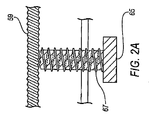
次に図2および4を参照すると、組織生検装置用の単一のモータの他の実施形態は、空気圧シリンダ60を含む。シリンダ60は、そのシリンダを流体圧制御システム150(図6)に適切な管類によって連結する案内穴61を含む。単一のモータ22は、案内穴61で提供された作動液の圧力に応答してシリンダ60内で往復運動するピストン63を含む。ピストン63は、ピストン63を内側カニューレ17に取り付けるための中心孔64を含む。好ましくは、軸受け45が提供され、内側カニューレ17とピストン63の中心孔64間に配置されるように寸法設定される。軸受け45は、軸受け表面でほぼ気密性の封止を維持したままで内側カニューレがその長手方向軸の周りで回転することを可能にするようになされている。一実施形態では、軸受け45は、内側カニューレ17上に圧入される。内側カニューレと軸受け45の間の係合を、止めねじ(図示せず)の使用あるいは接着剤またはエポキシ樹脂によって強化することができる。いずれにしても、モータ22が最終的には内側カニューレ17を外側カニューレ内で軸方向に駆動しなければならないので、内側カニューレおよびピストン63が共に並進運動することが不可欠である。
With reference now to FIGS. 2 and 4, another embodiment of a single motor for a tissue biopsy device includes a
内側カニューレ17の並進運動の提供に加え、ピストン63の動きは、内側カニューレ17の回転運動も引き起こすための機構として働くことを理解されたい。図2Aに最良に示すように、内側カニューレ17は、ねじ部分59を含み、そのねじ部分59は、そのねじ部分59に相補的なねじ山を含む、選択的に係合可能なナット65と関連するようになされている。ピストン63が圧縮されるにつれて、内側カニューレ17は、組織生検装置10の遠位端に向かって前進させられる。ナット65が押し下げられるときに、ねじ部分59およびナット65が協働して、ピストン63が圧縮されるにつれて内側カニューレを回転させる。
It should be understood that in addition to providing translational movement of the
ナット65は、付勢ばね67を含むことができ、その付勢ばね67は、組織が切除された後でナット65が解放されるときに、ナット65を内側カニューレ17のねじ部分59と非係合状態にする。上述のようにナット65を、組織切取り装置10に空気圧が供給されるときに内側カニューレ17のねじ部分59と自動的に係合し、空気圧が組織切取り装置10から取り除かれるときに自動的に切り離すようにすることができる。
The
シリンダ60の遠位端74とピストン63の間に戻しばね66が配置される。組織が切除され、ナット65が非係合状態にされた後で、戻しばね66は、ピストン63をその初期位置に戻し、したがって、組織が切除された後に生検装置の遠位端から離れるように内側カニューレ17を後退させる。
A
上述のように、内側カニューレ17は、ハンドピース12内で移動する。好ましくは、ハンドピースのハウジング70は、内側カニューレ17を摺動式に支持するための両端の開口部73を備えている。遠位側のハウジング70が好ましくはプラスチック材料から形成されるので、スラスト軸受けおよび回転軸受けを必要とすることなく、ハウジングの開口部73を通るカニューレの低摩擦の軸方向の動きを収容することができる。
As described above, the
生検装置10のハンドピース12は、全ての動作部品を担持し、外側および内側カニューレを支持する。図1および3の生検装置を参照すると、ハンドピース12は、回転モータ20がその中に配置される遠位側のハウジング70を含む。ハウジング70の遠位端71は、取付け具72内に形成される。取付け具72は、結合(mating)フランジ77を外側カニューレのハブ75上に係合させる。ハブ75は、係合穴76内で外側カニューレ15を支持する。
The
本発明の一態様によれば、外側カニューレのハブ75とハウジング70の遠位端71の間の係合は、気密性である必要はない。言い換えれば、それらの2つの部分の間の取付け具の結合部分は、流体密封のシールを生成することができる必要はない。本発明の一実施形態によれば、外側カニューレ15を支持するためのハブ75とハウジング70の間の係合は、外側内腔27中を通り大気に至る漏出通路を提供する。組織生検装置10の使用の際に、内側カニューレ17の内側内腔34を通して吸引することは、内側内腔を通して組織を引くことになる。
According to one aspect of the present invention, the engagement between the
組織が内腔に沿ってさらに前進するときに、場合によっては、前進している組織の背後に真空を生み出すことがある。その場合のある時点では、組織サンプルの背後の真空は、サンプルを収集トラップ55に引き込もうと試みる、組織サンプルの正面の真空と等しいので、組織は内側内腔の長さに沿った前進を止める。したがって、外側内腔27中を通る漏出通路は、内側のカッタが切取りボードから後退するときに大気が組織サンプルの背後に入ることを許容する。大気は、前進している組織の背後の真空を除去するのを助け、吸引溝(channel)の長さを下り収集トラップ55までの組織の引き込みを促進する。しかし、特に、目標とする組織のより小さい「一掴み(bites)」が取られるいくつかの適用例では、大気漏出通路は不可欠ではない。
As the tissue advances further along the lumen, it may in some cases create a vacuum behind the advancing tissue. At some point in that case, the tissue stops advancing along the length of the inner lumen because the vacuum behind the tissue sample is equal to the vacuum in front of the tissue sample attempting to draw the sample into the
好ましくは、取付け具72および結合フランジ77を、単純なねじり動作によって、最も好ましくは、ルアータイプの取付け具によって係合することができる。使用の際には、カニューレのハブ75が、ハンドピース12上に取り付けられ、それにより、外側カニューレ15を支持する。次いで、外側カニューレをサンプルの場所に隣接する体内に突出させるようにハンドピースを使用することができる。生検装置10のある特定の使用の際には、カニューレのハブ75からハンドピース12を取り外し、外側カニューレ15を患者内に残すことが望ましい。例えば、外側カニューレ15は、麻酔薬を導入するために使用することができる。他の適用例では、一度目標組織が完全に切除されたときに、除去された物質の位置にしるしをつけるために放射線不透過のマーカを案内するように外側カニューレを使用することができる。
Preferably, the
再びハウジング70の説明に戻ると、ハウジングは、アクセス開口部81(図1)を通して開放される内側空隙79(図2)を画定する。アクセス開口部81は、好ましくは、組織生検装置10の組立てを容易にするために提供される。装置の使用中に遠位端71に剛性を追加する1対の遠位側ブレース(brace)80を有するハウジング70の遠位端71を提供することができる。ブレース80は、遠位側ハウジング70が薄肉のプラスチックハウジングとして形成されることを可能にする。必要に応じて遠位側ハウジングの反対側の端部に同様のブレースを提供し、ハウジングに剛性を追加することができる。
Returning again to the description of the
図4の切取り装置は、往復動モータ22および特にシリンダ60を支持するように形成される。したがって、本発明の一実施形態では、遠位側ハウジング70の近位端83は、圧力式取付け具(pressure fitting)84を画定する。こうした圧力式取付け具84は、シリンダ60の遠位端88とハウジングの近位端83の間に緊密な漏れ防止係合を提供することを理解されたい。特定の一実施形態では、圧力式取付け具84は、戻しばね66の一部分がその中に載るばね空隙85を形成する。さらに、特定の実施形態では、圧力式取付け具84は、遠位側ピストン停止部86を画定する。ピストン63は、ストロークの端部でそれらの停止部と接触する。ピストン停止部86の位置は、切取り縁部が生検組織をきれいに切り取ることが可能になるように、切取り縁部35が切取り要素11の作用端で切取りボード31に接触することを可能にするように較正することができる。シリンダ60は、最初は、端部が開放したカップの形状で提供される。遠位端88に対応するその開放端は、圧力式取付け具84に取り付けられる。特定の実施形態では、圧力式取付け具は、ねじ山係合、圧入または接着剤の構成を含むことができる。
The cutting device of FIG. 4 is formed to support the
したがって、シリンダカップは、閉じられた近位端89を含む。この近位端は、案内穴61、ならびに内側カニューレが貫通する中央開口部62(図4)を画定する。好ましくは、シリンダ60の近位端89は、内側カニューレに対し、それがピストン63の動きによってシリンダ内で往復運動および回転するときでさえ、実質上気密封止を提供するように形成される。シリンダ60の近位端89は、近位側のピストン停止部90を画定し、その近位側ピストン停止部90は、外側シリンダの壁面に隣接するか、または近位端の中心部分にあることが可能である。こうした近位側ピストン停止部90は、シリンダ内の圧力が低減したときに戻しばね66の作用の下でピストン63が逆方向に移動することを制限する。
Accordingly, the cylinder cup includes a closed
本発明のさらなる態様では、収集トラップ55は、支持ハウジング93によってハンドピース12に取り付けられる。いくつかの実施形態では、ハンドピース12を上記で説明した部品に限定することができることを理解されたい。その場合には、収集トラップ55は、ハンドピースとは別個にそれと離れて、好ましくは、真空または吸引圧力の供給源の近くに位置することができる。その場合、吸引管50の近位端は、一定の長さの管類によって収集トラップ55に連結されるようになる。収集トラップ55がない状態で、吸引管50は、シリンダ60の近位端から離間及び接近するように往復運動するので、ハンドピースが吸引管の往復運動の端部を隠すように形成されたカバーを含むことが好ましい。
In a further aspect of the invention, the
しかし、最も好ましい実施形態によれば、収集トラップ55は、ハンドピース12に着脱可能に取り付けられる。長手方向に延びる1対のアーム94が、その間にアクセス開口部95を画定し、支持ハウジング93を形成する。支持ハウジング93は、シリンダ60の近位端89と係合する遠位端の取付け具96を含む。好ましくは、それらの2つの部品の間の連結がほぼ気密式である様々な係合が企図される。支持ハウジング93の近位端97は、円筒形の取付けハブ98を形成する。図1に最良に示すように、取付けハブ98は、収集トラップ55の近位端を囲繞する。ハブは、トラップ55のハウジング102に取り付けられたピン103を受ける差込みタイプ(bayonet−type)の取付け溝99を形成する。収集トラップ55と支持ハウジング93の間の差込み式の取付部と係合するために必要とされるねじり動作を容易にするために、1対の直径方向に対向する翼104をハウジング102上に提供することができる。好ましい実施形態が差込み式取付部を企図する一方、収集トラップ55を支持ハウジング93に着脱可能に連結するための他の構成が企図される。本発明の特徴の1つと合致するように、こうした係合の機構をプラスチックで形成することが可能であることが好ましい。
However, according to the most preferred embodiment, the
往復吸引管を収容するため、支持ハウジング93は、ハウジングの近位端と遠位端の間を延びる吸引通路100を有する。吸引管50は往復運動するので、好ましくは収集トラップ55内に延びない。切除された組織がトラップ55中に引かれるときに、往復吸引管50は、トラップ内に保持された生検物質と接触することがある。管のこうした動きは、組織を管の端部内に押しやり、それにより管を詰まらせる恐れがある。さらに、吸引管の往復運動は、組織をトラップの端部内に圧縮し、それにより吸引機能を停止させる恐れがある。
To accommodate the reciprocating suction tube, the support housing 93 has a
収集トラップ55は、上述のようにハウジング102を含む。そのハウジングは、案内穴107を形成し、その案内穴107は、真空発生装置に連結可能である。好ましくは、本発明によれば、流体圧制御システム150への適切な管類は、案内穴107と連結する。トラップ55は、そのトラップ内に取り付けられたフィルタ要素110を含む。好ましい実施形態では、フィルタ要素は、切除された生検組織サンプル、および分割された(morcellized)組織さえも保持しながら、空気、血液および他の流体の容易な通過を可能にする、網状のフィルタである。さらに、好ましくは、フィルタ要素110は、フィルタ要素の下端部(bottom end)においてだけでなく、要素110の少なくとも近位部分の周方向においても真空または吸引圧力を引くことができるように構成される。このようにして、物質がフィルタの近位端に向かって引かれるときでさえ、やはり真空をフィルタの他の部分を通して引くことができ、それにより吸引回路を維持する。
The
本発明は、図6のダイヤグラムに示すような流体圧制御システム150を企図する。好ましくは、制御システムの大部分が中央コンソール(console)内に収容される。そのコンソールは、加圧流体供給源152に連結される。好ましくは、その流体供給源は、ろ過された空気の調整された供給を制御システム150に提供する。
The present invention contemplates a fluid
図6のダイヤグラムに示すように、供給源からの加圧流体は、制御システム中のいくつかの地点152で供給される。より具体的には、加圧流体は、制御システムの基盤を形成する5つの弁に提供される。
As shown in the diagram of FIG. 6, pressurized fluid from a source is supplied at
図6のダイヤグラムの中央左側では、加圧流体152は、圧力調整器154および計器155を通る。計器155は、好ましくは外科医または医療技術者が見るために、コンソール上に取り付けられる。圧力調整器154は、供給源152から2位置流体圧弁158に提供される加圧流体を制御するために手動で調整可能である。弁158を流路158aと流路158bの間で切り換えることができる。戻しばね159が、流体圧弁をその平常位置158aに付勢する。
On the center left side of the diagram of FIG. 6,
流路158aの付勢された平常の位置において、弁158は、シリンダ圧力ライン161を流体供給源152に連結する。その圧力ライン161は、調整可能な流量制御弁162を通り、その流量制御弁162を、圧力ライン161を通る流体の流量を調整するために使用することができる。圧力計155および圧力調整器154のように、調整可能な流量制御弁162を手術処置中の操作のためにコンソール上に取り付けることができる。
In the energized normal position of the
圧力ライン161は、往復動モータ22の案内穴61に連結される。したがって、流体圧制御システム150の平常または初期位置において、流体圧が、戻しばね66の付勢力に対抗してピストン63を駆動するようにシリンダ60に提供される。より具体的には、図4を参照すると、流体圧弁158の初期位置は、往復動モータおよび内側カニューレが切取り要素の遠位端に向かって駆動されるようになっている。この構成では、内側カニューレ17は、外側カニューレ15の組織受取り開口部25を覆う。内側カニューレがそのように配置された状態では、組織が早まって組織受取り開口部25を満たしてしまうおそれなしに、外側カニューレを患者に導入することができる。
The
加圧流体は、シリンダ圧力ライン161に沿って圧力スイッチ165にも送り込まれる。圧力スイッチは、流路165aおよび165bを提供する2つの位置を有する。さらに、調整可能な戻しばね166は、圧力供給源152からの流体が弁内で終了する平常位置まで、スイッチを付勢する。しかし、加圧流体がシリンダ圧力ライン161を通して供給されると、圧力スイッチ165は、流路165bまで動き、そこで流体供給源152が圧力入力ライン168に流体連結される。この圧力入力ライン168は、揺動(oscillating)流体圧弁170に圧力供給する。その弁は、主として、2位置流体圧弁158の加圧と解放を交互に行うことによって往復動モータ22を揺動するように動作する。圧力スイッチ165は、ピストン66がストロークの端部に達したときに生じる、シリンダ圧力ライン161内または往復動モータのシリンダ60内の圧力の上昇を感知するように較正される。より具体的には、ピストンは、内側カニューレ17が切取りボード31に接触するときにそのストローク端に達する。この時点で、ピストンの背後の流体圧が増大し、その増大は、圧力弁165によって感知されて、弁を流路165bまでストローク(stroke)させる。
The pressurized fluid is also fed into the
揺動流体圧弁170は、流路170aおよび170bを提供する2つの位置を有する。位置170aで、入力ライン179は、揺動圧力出力ライン172に供給される。流路170bでは、入力ライン179は、閉鎖ライン171に供給される。したがって、流体圧が圧力スイッチ165から(流路165bを通して)提供された状態で、揺動弁170は流路170aを開き、出力ライン172に沿って流体圧弁158の入力に至る流体回路を完成させる。
The oscillating
出力ライン172への流体圧は、入力ライン179内に流体圧が存在するときにのみ生じる。この入力ラインは、弁176によって圧力供給され、その弁176は、足ペダル175によって操作される。弁176は、戻しばね177によって、流路176aのある初期位置まで付勢される。しかし、足ペダル175が押し下げられるときには、弁176は、流路176bまで、ばねの力に対抗して動く。この位置では、供給源152からの加圧流体は、足ペダル入力ライン179に連結される。揺動流体圧弁170がその初期位置である流路170aにあるときに、加圧流体は、入力ライン179中を通って出力ライン172まで流れ、最終的には流体圧弁158に至る。
Fluid pressure to the
出力ライン172の流体圧は、弁158を流路158bに切り換える。この位置では、ピストン63の背後の流体圧が解除されて、戻しばね66がピストンを近位端に向けて押しやる。より具体的には、戻しばねは、内側カニューレ17を組織切断開口部25から後退させる。ライン161の流体圧の解除によって、戻しばね166の作用により、圧力スイッチ165は流路165aの初期の中立位置に戻される。次に、流路165aでは、圧力入力ライン168は、もはや流体供給源152に連結されておらず、そこで加圧流体は、揺動流体圧弁170に提供されない。この弁はばねによって特定の状態に付勢されていないので、本明細書に説明した状況を除き、その位置は必ずしも変化しない。
The fluid pressure in
足ペダル175および弁176に戻ると、一度足ペダルが解放されると、付勢ばね177は、弁176をその流路176bからその平常の初期流路176aまで押しやる。この位置では、足ペダル入力ライン179は、もはや流体供給源152に連結されていない。揺動弁170が流路170aにあるときは、出力ライン172を通る流体圧は除去される。このような流体圧の低減に応答して、流体圧弁158は、戻しばね159の動作によってその最初の流路158aに切り換わる。この位置では、シリンダ圧力ライン161は、流体供給源152に再び連結され、それにより、往復動モータ22が内側カニューレ17を組織受取り開口部25を塞ぐ位置まで伸長させる。したがって、本発明によれば、流体圧制御システム150は、組織受取り開口部が閉じた状態で組織生検装置10を開始および終了する。装置を患者から取り出すときに、追加の組織を切取り要素11内に閉じ込めるか、またははさむことがないように、一度その手技が完了すると開口部を閉じることは重要である。
Returning to
これまで、流体圧制御システム150の、往復動モータ22の動作を制御する部分を説明してきた。システム150は、回転モータ20の動作も制御する。やはり、最も好ましい実施形態では、モータ20は空気モータである。こうした空気モータは、他の流体圧弁182によって制御される。図6に示すように、弁の初期位置は、流体供給源152が閉鎖ライン183に連結される流路182aを提供する。しかし、流体圧弁182が加圧されるときには、弁の位置は、流体供給源152が空気モータの案内穴40に連結される流路まで移動する。その位置では、加圧流体は、連続して空気モータ20を駆動し、それにより内側カニューレ17を回転する。ちなみに、騒音を低減するために空気モータ上に消音器Mを提供することができることに留意することができる。
So far, the portion of the fluid
回転モータの流体圧弁182は、圧力作動ライン180の流体圧によって制御される。その圧力ライン180は、足ペダル入力ライン179から分岐しており、足ペダルスイッチ176に連結されている。足ペダル175が押し下げられるときに、スイッチはその流路176bまで動く。その位置では、圧力作動ライン180は、流体供給源152に連結され、そのため、流体圧が回転モータ流体圧弁182に直接提供される。他の流体圧弁と同様に、弁182は、弁への入力において流体圧が打ち勝たなければならない付勢ばね184を含む。
The
回転モータ20の流体の制御は、揺動流体圧弁170を介して供給されないので、モータは、足ペダル175が押し下げられている限り連続して動作することを理解されたい。さらに、回転モータ20の速度は、図示の実施形態では調整可能ではないことも明らかである。モータ20が、好ましくは固定圧力に調整された流体供給源152に直接連結されるので、空気モータは、実際には1つの速度で動作する。その一方で、上記したように、往復動モータ22は、圧力調整器154および流量制御弁162を介して圧力供給される。したがって、切取り刃35の往復運動の速度は、外科医または医療技術者による制御を受ける。切取り要素11の往復運動は、サンプリングされた組織、取り出した組織生検サンプルの寸法、および特定の患者に対する特定の他の要因の関数とすることができる。それらの同じ要因は一般に、内側カニューレを回転させることによって実現する切取り縁部35のスライス特性に影響しない。
It should be understood that since the fluid control of the
流体圧制御システム150は、内側カニューレ17を含む吸引導管中を通って加えられる吸引圧力または真空も調整する。図示の実施形態では、圧力作動ライン180は、吸引弁185に供給するように分岐する。その弁は、最初の流路185aから第2の流路185bまで移動可能である。最初の流路では、流体供給源152は、閉鎖ライン186に連結される。しかし、流体圧がライン180に加えられるときに、弁185は、付勢ばね187に対抗して流路185bに切り換える。その通路では、ベンチュリ要素190が流体供給源に連結される。したがって、そのベンチュリ要素は、真空制御ライン193および吸引ライン191内で真空を発生させる。やはり、空気モータと同様に、ベンチュリ要素190は、ハンドピース内の騒音を低減するために消音器Mを含むことができる。
The fluid
足ペダル175が押し下げられ、弁176が流路176bにある限り、流体圧は連続して吸引流体圧弁185に加えられ、ベンチュリ要素190は、連続して真空圧力または吸引の負圧を発生する。回転モータの動作と同様に、この真空は最も好ましい実施形態では調整されない。しかし、真空圧力は、適切なベンチュリ部品190の選択によって較正することができる。
As long as the
ベンチュリ部品190が動作しているときは、制御ライン193に導かれる真空は、真空スイッチ194に対して動作する。可変の付勢ばね195は、最初は真空スイッチ194を流路194aに維持する。その流路では、真空入力ライン196は、他のどのラインにも連結されない。しかし、制御ライン193の所定の真空で、弁は流路194bまで動く。その位置では、真空入力ライン196は、圧力ライン192に連結される。好ましい実施形態では、言い換えれば、真空スイッチ194は、「作動―非作動(go−nogo)」スイッチの形状で動作し、吸引真空が所定の動作閾値に達するときに、真空スイッチが作動する。真空スイッチ194が最初に作動させられると、足ペダルが押し下げられている限りそれは作動状態のままである。したがって、真空入力ライン196は、足ペダル175が押し下げられている限り、圧力ライン192に継続して連結される。
When the
流体圧弁158に戻ると、ライン192、および最終的に真空入力ライン196の流体圧は、弁158の状態によって決定される。調整された流体圧が往復動モータ22に提供される流路158aに弁158があるときには、圧力ライン192は働いていない。しかし、弁158が流路158bまで移動すると、圧力ライン192は、調整された流体供給源に連結される。次いで、加圧流体は、圧力ライン192から真空スイッチ流路194bを通り、真空入力ライン196を通り揺動弁170の左側に流れ、それにより、弁を流路170bまでストロークさせる。揺動弁170がこの流路にあるときは、出力ライン172は働かず、それにより、弁158が戻しばね159の影響の下で流路158aまで動くことが可能になる。その状態では、弁158により、加圧流体が再度往復動モータ22に流れ、次の切取りストロークによってそれを動かすことが可能になる。
Returning to the
したがって、弁158および真空スイッチ194の両方が代替の状態に移動されるときには、加圧流体は、ライン192から、真空入力ライン196を通り、調整可能な流量制御弁197を通り揺動流体圧弁170の第2の入力まで通る。真空入力ライン196の圧力は、揺動弁170を流路170bのための第2の位置に切り換える。その位置では、足ペダル弁176を通る加圧流体は弁170内で終わる。その結果、出力ライン172の圧力は下がり、それにより、流体圧弁158が戻しばね159の動作の下で当初の位置158aに戻ることが可能になる。その位置では、流体圧は、やはり往復動モータ22に供給されて、ピストン66が切取りストロークによって動く。
Thus, when both
揺動弁170がライン168および196の流体圧の影響を受け、それらのラインが、同時に完全に加圧されることがないことを理解されたい。システムが最初に通電されると、供給源152からの圧力は、自動的に往復動モータ22および圧力弁165に供給され、それにより、弁が流路165bに動く。その状態では、ライン168が加圧され、それにより、揺動弁170を状態170aの左側に切り換える。揺動弁は、圧力スイッチ165の位置にかかわらずライン196が加圧されるまでその状態のままである。好ましい実施形態では、ライン196の流体圧は、足ペダル175が押し下げられ吸引回路が動作真空に達するまで、動作レベルに増大しないことも理解できよう。
It should be understood that the
代替の実施形態では、真空の小さな変化を感知するように真空スイッチ194を較正することができる。その代替の実施形態では、この戻りストロークの完了を真空スイッチ194の状態によって判定することができる。真空スイッチ194は、組織サンプルが吸引導管中を通して収集トラップ55内に完全に引き込まれたことを示す表示器として動作することができる。より具体的には、内側カニューレが大気圧に開放されたとき、真空スイッチ194によって感知される真空は1つの値を有する。その真空圧力は、組織サンプルが内側カニューレ17中で引っ張られるときに変化する。内側カニューレが再度大気圧に対して開放するように組織が取り除かれるときに、その真空の圧力は再度変化する。この時点で、内側カニューレ17は空であり、他の組織サンプルを切除するために切取りストロークを再び行うことのできる状態にある。したがって、真空スイッチ194は、流路194bにストロークして、揺動弁170の左側に流体圧を提供し、それにより、弁を流路170bまでストロークさせる。
In an alternative embodiment, the
流体圧制御システム150は、軸方向モータ22を連続的に往復動させるための完全なシステムを提供することをこの詳細な説明から理解することができる。さらに、そのシステムは、足ペダル175が押し下げられている限りは、一定の連続した圧力を回転モータ20および吸引ライン191の両方に提供する。一度足ペダルが解放されると、作動ライン180中の流体圧が下がり、それにより、空気モータ制御弁182および吸引制御弁185が当初のまたは平常の位置に切り替わり、そこで、流体圧がそれぞれの構成部品に対して終了する。しかし、好ましい実施形態では、往復動モータ22は、流体供給源152に直接連結された弁158を通して圧力供給されるので、圧力は往復動モータ22に対して維持される。
It can be seen from this detailed description that the fluid
流体圧制御システム150は、図示の実施形態では、5つの制御可能な要素を組み込む。1つ目は、往復動モータ22を作動させるために提供された流体圧は、調節器154によって制御される。さらに、流体のピストン63への流量は、調整可能な制御弁162によって制御される。圧力スイッチ165が作動する圧力は、調整可能な戻しばね166によって決定される。同様に、真空スイッチ194が作動される吸引圧力の真空は、調整可能な戻しばね195によって制御される。最後に、調整可能な流量制御弁197は、真空スイッチ194から揺動流体圧弁170までの流体の流れを制御する。それらの調整可能な要素はそれぞれ、往復動モータ22の往復運動の速度および時間を制御する。
The fluid
好ましい実施形態では、圧力スイッチ165は、本質的には、「ストロークの端部」を示す表示器として動作する。言い換えれば、内側カニューレ17が前進または切取りストロークの端部に達すると、内側カニューレ17は切取りボード31に接触する。切取りボードと接触するときに、シリンダ圧力ライン161の圧力は劇的に変化する。この変化によって、圧力スイッチ165が状態を変化させる。こうした状態の変化によって揺動弁170は弁158を切り換えて、流体圧をモータ22に対して終了させ、それにより、切取りストロークを終了し、戻りストロークを開始させる。
In the preferred embodiment, the
戻りストローク中には、切除された組織サンプルは、吸引導管に沿って徐々に引かれる。また、戻りストローク中には、圧力流体が、圧力ライン161および圧力スイッチ165から、最終的には揺動弁170に供給するライン168から流れ出る。この揺動弁がストロークするときには、流体圧は、弁158から漏出し、それにより、弁が状態158aに戻って、新しい切取りストロークのためにモータ22を加圧することが可能になる。それぞれの流体圧弁の動作は、固有の時間の遅れを導入するので、往復動モータ22への圧力が回復するときまでに、吸引真空は、組織サンプルを吸引導管全体を通して収集トラップ55内に引き込む。
During the return stroke, the excised tissue sample is gradually drawn along the suction conduit. Also, during the return stroke, the pressure fluid flows out of the
流体圧的に制御された内側切取りカニューレの使用は、従来の組織切取り装置に対して重要な利点を提供する。流体圧装置の使用により、ほとんどの動作部品を医療等級のプラスチックなど、高価でない軽量の非金属の材料から形成することができる。本発明の流体圧システムは、電気部品の必要をなくし、それは、患者を保護するための電気的な絶縁が不要になるということである。 The use of a hydraulically controlled inner cutting cannula provides significant advantages over conventional tissue cutting devices. Through the use of fluid pressure devices, most moving parts can be formed from inexpensive, lightweight non-metallic materials such as medical grade plastic. The fluid pressure system of the present invention eliminates the need for electrical components, which eliminates the need for electrical insulation to protect the patient.
おそらく最も重要なことには、流体的に制御された内側切取りカニューレの往復運動は、生検組織のよりきれいでよく制御された切取りを提供する。往復動モータ22が実質的に一定の加圧流体の供給源から供給されるので、モータピストン63の背後の圧力は、切取りストローク中ずっとほぼ一定のままである。そのほぼ一定の圧力によって、内側切取りカニューレは、組織自体によって決められる或る速度で、生検組織中を前進することができる。
Perhaps most importantly, the reciprocation of the fluidly controlled inner cutting cannula provides a cleaner and better controlled cutting of the biopsy tissue. Since the
言い換えれば、切取り縁部35が切取りストローク中により硬い組織に出合うときは、モータピストン63、したがって内側カニューレ17の前進速度は、これに応じて低下する。こうした特徴は、切取り縁部が組織を単に押してしまうおそれなしに組織を通ってきれいに切取ることを可能にする。切取り縁部の回転は、切取り作用を容易にすることができる。内側カニューレがより低密度の組織に出合うときには、ピストン63の背後の一定の圧力により切取り縁部が組織を通ってより素早く前進することが可能になる。
In other words, when the
代替の実施形態では、回転モータ20は、空気圧モータではなく、電気モータから構成することができる。図7に示すように、圧力作動ライン180を、調整可能な付勢ばね199によって制御されるオン/オフ圧力スイッチ198に供給することができる。作動ライン180が加圧されると、スイッチ198は、電気往復動モータ22とバッテリパック200の間を連結させる。好ましくは、バッテリパック200は、ハンドピース12に取り付けられるが、その代わりにコンソール内に収容された外部バッテリに接続することができる。
In an alternative embodiment, the
上述の説明は、本発明の実施形態を例示し説明するためにのみ示されている。網羅的であるか、または本発明を開示した厳密な形態に限定することは意図されていない。本発明は、本発明の範囲の精神から逸脱することなく、実施することができるか、あるいは具体的に説明し図示することができる。本発明の範囲は、添付の特許請求の範囲によって定義されるものである。 The foregoing description has been presented only to illustrate and describe embodiments of the invention. It is not intended to be exhaustive or to limit the invention to the precise form disclosed. The present invention may be practiced or specifically described and illustrated without departing from the spirit of the scope of the invention. The scope of the present invention is defined by the appended claims.
Claims (10)
前記外側内腔内に摺動可能に配置され、開放した遠位端から、これに対向する開放した近位端まで延びる内側内腔を画定する内側カニューレであって、前記開放した遠位端において、前記組織受取り開口部を通って突出する組織を切断するように動作可能である切取り縁部を画定する、内側カニューレと、
前記内側カニューレに動作可能に結合されており、且つ、前記外側カニューレ内で前記内側カニューレを回転させるモータであって、さらに、前記内側カニューレが回転している間に前記外側カニューレ内で前記内側カニューレを並進運動させる、モータと、
前記モータを電源に接続するシステムとを備える、組織切取り装置。 An outer cannula defining an outer lumen and a tissue receiving opening adjacent to the distal end of the outer cannula in communication with the outer lumen;
An inner cannula slidably disposed within the outer lumen and defining an inner lumen extending from an open distal end to an open proximal end opposite thereto, at the open distal end An inner cannula defining a cutting edge operable to cut tissue protruding through the tissue receiving opening;
A motor operably coupled to the inner cannula and for rotating the inner cannula within the outer cannula, and further wherein the inner cannula within the outer cannula while the inner cannula is rotating A motor that translates,
A tissue cutting device comprising a system for connecting the motor to a power source.
前記外側内腔内に摺動可能に配置され、開放した遠位端から、これに対向する開放した近位端まで延びる内側内腔を画定する、内側カニューレであって、前記開放した遠位端において、前記組織受取り開口部を通って突出する組織を切断するように動作可能である切取り縁部を画定する、内側カニューレと、
前記内側カニューレを回転運動させるように動作可能なロータアセンブリを有する流体圧モータであって、前記ロータアセンブリは、選択的に押下げ可能なナットと関連するねじ部を有する吸引管と連通しており、前記ねじ部および前記押下げ可能なナットは、前記ロータアセンブリが回転している間に前記ナットが前記ねじ部の上に押し下げられるとき、前記内側カニューレの並進運動を生じさせる、流体圧モータと、
前記流体圧モータを加圧流体の供給源に連結する流体圧システムとを備える、組織切取り装置。 An outer cannula defining an outer lumen and a tissue receiving opening adjacent to the distal end of the outer cannula in communication with the outer lumen;
An inner cannula slidably disposed within the outer lumen and defining an inner lumen extending from an open distal end to an opposite open proximal end, wherein the open distal end An inner cannula defining a cutting edge operable to cut tissue protruding through the tissue receiving opening;
A hydraulic motor having a rotor assembly operable to rotationally move the inner cannula, wherein the rotor assembly is in communication with a suction tube having a thread associated with a selectively depressible nut. A fluid pressure motor that causes translational movement of the inner cannula when the nut is pushed down over the threaded portion while the rotor assembly is rotating; ,
And a fluid pressure system that couples the fluid pressure motor to a source of pressurized fluid.
前記外側内腔内に摺動可能に配置され、開放した遠位端から、これに対向する開放した近位端まで延びる内側内腔を画定する、内側カニューレであって、前記開放した遠位端において、前記組織受取り開口部を通って突出する組織を切断するように動作可能である切取り縁部を画定する、内側カニューレと、
前記内側カニューレを並進運動させるように動作可能なピストンを有する流体圧モータであって、前記内側カニューレは、選択的に係合可能なナットと関連するねじ部を有し、前記ねじ部および前記ナットは、前記ピストンが圧縮するときに前記内側カニューレの回転運動を生じさせるように動作可能である、流体圧モータと、
前記流体圧モータを加圧流体の供給源に連結する流体圧システムとを備える、組織切取り装置。 An outer cannula defining an outer lumen and a tissue receiving opening adjacent to the distal end of the outer cannula in communication with the outer lumen;
An inner cannula slidably disposed within the outer lumen and defining an inner lumen extending from an open distal end to an opposite open proximal end, wherein the open distal end An inner cannula defining a cutting edge operable to cut tissue protruding through the tissue receiving opening;
A hydraulic motor having a piston operable to translate the inner cannula, the inner cannula having a thread associated with a selectively engageable nut, the thread and the nut A hydraulic motor operable to cause a rotational movement of the inner cannula as the piston compresses;
And a fluid pressure system that couples the fluid pressure motor to a source of pressurized fluid.
Applications Claiming Priority (2)
| Application Number | Priority Date | Filing Date | Title |
|---|---|---|---|
| US11/058,128 US20060184063A1 (en) | 2005-02-15 | 2005-02-15 | Single motor handheld biopsy device |
| PCT/US2006/004862 WO2006088755A1 (en) | 2005-02-15 | 2006-02-10 | Single motor hand-held biopsy apparatus |
Publications (1)
| Publication Number | Publication Date |
|---|---|
| JP2008529668A true JP2008529668A (en) | 2008-08-07 |
Family
ID=36579966
Family Applications (1)
| Application Number | Title | Priority Date | Filing Date |
|---|---|---|---|
| JP2007555270A Pending JP2008529668A (en) | 2005-02-15 | 2006-02-10 | Single motor hand-held biopsy device |
Country Status (6)
| Country | Link |
|---|---|
| US (1) | US20060184063A1 (en) |
| EP (1) | EP1858416A1 (en) |
| JP (1) | JP2008529668A (en) |
| CA (1) | CA2593113A1 (en) |
| MX (1) | MX2007009815A (en) |
| WO (1) | WO2006088755A1 (en) |
Cited By (1)
| Publication number | Priority date | Publication date | Assignee | Title |
|---|---|---|---|---|
| JP2008200481A (en) * | 2006-12-13 | 2008-09-04 | Ethicon Endo Surgery Inc | Biopsy system equipped with vacuum control module |
Families Citing this family (74)
| Publication number | Priority date | Publication date | Assignee | Title |
|---|---|---|---|---|
| MXPA04008781A (en) | 2002-03-19 | 2005-12-15 | Bard Dublin Itc Ltd | Biopsy device and biopsy needle module that can be inserted into the biopsy device. |
| DE10390947D2 (en) | 2002-03-19 | 2005-06-09 | Dublin Itc Ltd Crawley Bard | Vacuum biopsy device |
| US8142365B2 (en) | 2002-05-31 | 2012-03-27 | Vidacare Corporation | Apparatus and method for accessing the bone marrow of the sternum |
| US7951089B2 (en) | 2002-05-31 | 2011-05-31 | Vidacare Corporation | Apparatus and methods to harvest bone and bone marrow |
| US9451968B2 (en) | 2002-05-31 | 2016-09-27 | Vidacare LLC | Powered drivers, intraosseous devices and methods to access bone marrow |
| DE60328386D1 (en) | 2002-05-31 | 2009-08-27 | Vidacare Corp | DEVICE AND METHOD FOR ACHIEVING BONE MARROW |
| US10973532B2 (en) | 2002-05-31 | 2021-04-13 | Teleflex Life Sciences Limited | Powered drivers, intraosseous devices and methods to access bone marrow |
| US20070049945A1 (en) | 2002-05-31 | 2007-03-01 | Miller Larry J | Apparatus and methods to install, support and/or monitor performance of intraosseous devices |
| US11298202B2 (en) | 2002-05-31 | 2022-04-12 | Teleflex Life Sciences Limited | Biopsy devices and related methods |
| US8641715B2 (en) | 2002-05-31 | 2014-02-04 | Vidacare Corporation | Manual intraosseous device |
| US7811260B2 (en) | 2002-05-31 | 2010-10-12 | Vidacare Corporation | Apparatus and method to inject fluids into bone marrow and other target sites |
| US10973545B2 (en) | 2002-05-31 | 2021-04-13 | Teleflex Life Sciences Limited | Powered drivers, intraosseous devices and methods to access bone marrow |
| US8690791B2 (en) | 2002-05-31 | 2014-04-08 | Vidacare Corporation | Apparatus and method to access the bone marrow |
| WO2008033872A2 (en) | 2006-09-12 | 2008-03-20 | Vidacare Corporation | Biopsy devices and related methods |
| US9314228B2 (en) | 2002-05-31 | 2016-04-19 | Vidacare LLC | Apparatus and method for accessing the bone marrow |
| US9072543B2 (en) | 2002-05-31 | 2015-07-07 | Vidacare LLC | Vascular access kits and methods |
| US8668698B2 (en) | 2002-05-31 | 2014-03-11 | Vidacare Corporation | Assembly for coupling powered driver with intraosseous device |
| US11337728B2 (en) | 2002-05-31 | 2022-05-24 | Teleflex Life Sciences Limited | Powered drivers, intraosseous devices and methods to access bone marrow |
| DE10314240A1 (en) | 2003-03-29 | 2004-10-07 | Bard Dublin Itc Ltd., Crawley | Pressure generating unit |
| US9504477B2 (en) | 2003-05-30 | 2016-11-29 | Vidacare LLC | Powered driver |
| US7815642B2 (en) | 2004-01-26 | 2010-10-19 | Vidacare Corporation | Impact-driven intraosseous needle |
| ATE425705T1 (en) | 2004-01-26 | 2009-04-15 | Vidacare Corp | MANUAL INTEROSSARY DEVICE |
| US8864680B2 (en) | 2004-07-09 | 2014-10-21 | Bard Peripheral Vascular, Inc. | Transport system for biopsy device |
| US8998848B2 (en) | 2004-11-12 | 2015-04-07 | Vidacare LLC | Intraosseous device and methods for accessing bone marrow in the sternum and other target areas |
| US7517321B2 (en) | 2005-01-31 | 2009-04-14 | C. R. Bard, Inc. | Quick cycle biopsy system |
| US8267868B2 (en) | 2005-08-10 | 2012-09-18 | C. R. Bard, Inc. | Single-insertion, multiple sample biopsy device with integrated markers |
| EP1921999B1 (en) | 2005-08-10 | 2015-08-05 | C.R.Bard, Inc. | Single-insertion, multiple sampling biopsy device usable with various transport systems |
| US8262585B2 (en) | 2005-08-10 | 2012-09-11 | C. R. Bard, Inc. | Single-insertion, multiple sampling biopsy device with linear drive |
| WO2008024684A2 (en) | 2006-08-21 | 2008-02-28 | C.R. Bard, Inc. | Self-contained handheld biopsy needle |
| EP2068743B1 (en) | 2006-09-12 | 2017-03-15 | Vidacare LLC | Medical procedures trays, kits and related methods |
| EP3189787B1 (en) | 2006-09-12 | 2019-01-09 | Teleflex Medical Devices S.à.r.l. | Medical procedures trays and related methods |
| EP2068725B1 (en) | 2006-09-12 | 2016-11-09 | Vidacare LLC | Apparatus for biopsy and aspiration of bone marrow |
| US8944069B2 (en) | 2006-09-12 | 2015-02-03 | Vidacare Corporation | Assemblies for coupling intraosseous (IO) devices to powered drivers |
| EP2343014B1 (en) | 2006-10-06 | 2018-02-14 | Bard Peripheral Vascular, Inc. | Tissue handling system with reduced operator exposure |
| EP2086417B1 (en) | 2006-10-24 | 2015-07-01 | C.R.Bard, Inc. | Large sample low aspect ratio biopsy needle |
| US8974410B2 (en) | 2006-10-30 | 2015-03-10 | Vidacare LLC | Apparatus and methods to communicate fluids and/or support intraosseous devices |
| US20090112119A1 (en) * | 2007-10-31 | 2009-04-30 | Kim Stanley I | Rotating biopsy device and biopsy robot |
| US8241225B2 (en) | 2007-12-20 | 2012-08-14 | C. R. Bard, Inc. | Biopsy device |
| US7854706B2 (en) | 2007-12-27 | 2010-12-21 | Devicor Medical Products, Inc. | Clutch and valving system for tetherless biopsy device |
| DE102008061063B4 (en) * | 2008-10-29 | 2016-12-29 | Erbe Elektromedizin Gmbh | Cryoprobe, cryosurgical device |
| WO2010082139A1 (en) * | 2009-01-13 | 2010-07-22 | Leadex Cardiac Ltd. | Lead extraction methods and apparatus |
| BRPI0924422A2 (en) | 2009-03-16 | 2016-01-26 | Bard Inc C R | biopsy device and method for controlling a biopsy device |
| JP2012523888A (en) | 2009-04-15 | 2012-10-11 | シー・アール・バード・インコーポレーテッド | Biopsy instrument with integrated fluid management system |
| US8206316B2 (en) | 2009-06-12 | 2012-06-26 | Devicor Medical Products, Inc. | Tetherless biopsy device with reusable portion |
| EP3572002A1 (en) | 2009-08-12 | 2019-11-27 | C.R. Bard Inc. | Biopsy apparatus having integrated thumbwheel mechanism for manual rotation of biopsy cannula |
| US8283890B2 (en) | 2009-09-25 | 2012-10-09 | Bard Peripheral Vascular, Inc. | Charging station for battery powered biopsy apparatus |
| US8485989B2 (en) | 2009-09-01 | 2013-07-16 | Bard Peripheral Vascular, Inc. | Biopsy apparatus having a tissue sample retrieval mechanism |
| US8430824B2 (en) | 2009-10-29 | 2013-04-30 | Bard Peripheral Vascular, Inc. | Biopsy driver assembly having a control circuit for conserving battery power |
| US8597206B2 (en) | 2009-10-12 | 2013-12-03 | Bard Peripheral Vascular, Inc. | Biopsy probe assembly having a mechanism to prevent misalignment of components prior to installation |
| US9839740B2 (en) | 2010-02-02 | 2017-12-12 | Teleflex Medical Devices S.À R.L | Intraosseous-needle stabilizer and methods |
| US8444573B2 (en) | 2010-03-30 | 2013-05-21 | Siteselect Medical Technologies, Inc. | Tissue excision device |
| JP2014513618A (en) * | 2011-04-01 | 2014-06-05 | リーデックス カーディアック リミテッド | Lead wire extraction method and apparatus |
| US8858465B2 (en) * | 2011-04-14 | 2014-10-14 | Devicor Medical Products, Inc. | Biopsy device with motorized needle firing |
| US9730729B2 (en) | 2011-07-11 | 2017-08-15 | Teleflex Medical Devices S.A R.L. | Sternal locators and associated systems and methods |
| EP2779923A1 (en) * | 2011-11-16 | 2014-09-24 | Vanderbilt University | Motive device for use in magnetically-sensitive environments |
| EP3498176B1 (en) | 2013-03-20 | 2021-04-28 | Bard Peripheral Vascular, Inc. | Biopsy device |
| EP3549533B1 (en) | 2013-11-05 | 2020-12-30 | C.R. Bard, Inc. | Biopsy device having integrated vacuum |
| US9713877B2 (en) | 2014-11-12 | 2017-07-25 | Medline Industries, Inc. | Clipper head with drag reduction |
| USD779123S1 (en) | 2014-11-12 | 2017-02-14 | Medline Industries, Inc. | Clipper head |
| CN111281442B (en) | 2015-05-01 | 2023-01-10 | C·R·巴德公司 | Biopsy device |
| US10321963B2 (en) * | 2015-08-04 | 2019-06-18 | Vanderbilt University | Apparatus and method for moving an elongate rod |
| USD795497S1 (en) | 2016-01-15 | 2017-08-22 | Medline Industries, Inc. | Clipper |
| USD794871S1 (en) | 2016-01-15 | 2017-08-15 | Medline Industries, Inc. | Clipper |
| USD802214S1 (en) | 2016-06-10 | 2017-11-07 | Medline Industries, Inc. | Clipper head |
| USD802216S1 (en) | 2016-06-10 | 2017-11-07 | Medline Industries, Inc. | Clipper head |
| USD802217S1 (en) | 2016-06-10 | 2017-11-07 | Medline Industries, Inc. | Clipper head |
| USD802215S1 (en) | 2016-06-10 | 2017-11-07 | Medline Industries, Inc. | Clipper head |
| US11160538B2 (en) * | 2016-10-31 | 2021-11-02 | Devicor Medical Products, Inc. | Biopsy device with linear actuator |
| EP3624697B1 (en) | 2017-05-19 | 2024-02-14 | Merit Medical Systems, Inc. | Biopsy needle devices and methods of use |
| WO2018213580A1 (en) | 2017-05-19 | 2018-11-22 | Merit Medical Systems, Inc. | Rotating biopsy needle |
| EP3624698A4 (en) | 2017-05-19 | 2021-06-09 | Merit Medical Systems, Inc. | Semi-automatic biopsy needle device and methods of use |
| US10548674B2 (en) * | 2017-07-06 | 2020-02-04 | YellowDot Innovations, LLC | Robotic guide for medical device |
| CN109984775B (en) * | 2019-04-09 | 2020-03-31 | 汕头大学医学院第一附属医院 | Oral cavity sample collection system for physical examination |
| CN116869582B (en) * | 2023-09-01 | 2023-11-28 | 浙江首鼎医学科技有限公司 | Biopsy needle sampling device based on puncture resistance |
Family Cites Families (9)
| Publication number | Priority date | Publication date | Assignee | Title |
|---|---|---|---|---|
| US5794626A (en) * | 1994-08-18 | 1998-08-18 | Kieturakis; Maciej J. | Excisional stereotactic apparatus |
| CA2287087C (en) * | 1998-10-23 | 2007-12-04 | Ethicon Endo-Surgery, Inc. | Surgical device for the collection of soft tissue |
| US6402701B1 (en) * | 1999-03-23 | 2002-06-11 | Fna Concepts, Llc | Biopsy needle instrument |
| US6758824B1 (en) * | 2000-11-06 | 2004-07-06 | Suros Surgical Systems, Inc. | Biopsy apparatus |
| US7226459B2 (en) * | 2001-10-26 | 2007-06-05 | Smith & Nephew, Inc. | Reciprocating rotary arthroscopic surgical instrument |
| US7740597B2 (en) * | 2002-12-11 | 2010-06-22 | Ethicon Endo-Surgery, Inc. | Biopsy device with sample tube |
| CA2517242C (en) * | 2003-02-25 | 2015-01-20 | Ethicon Endo-Surgery, Inc. | Biopsy device with variable speed cutter advance |
| US7169114B2 (en) * | 2003-06-04 | 2007-01-30 | Krause William R | Biopsy and delivery device |
| US7740594B2 (en) * | 2004-09-29 | 2010-06-22 | Ethicon Endo-Surgery, Inc. | Cutter for biopsy device |
-
2005
- 2005-02-15 US US11/058,128 patent/US20060184063A1/en not_active Abandoned
-
2006
- 2006-02-10 MX MX2007009815A patent/MX2007009815A/en unknown
- 2006-02-10 WO PCT/US2006/004862 patent/WO2006088755A1/en active Application Filing
- 2006-02-10 EP EP06734822A patent/EP1858416A1/en not_active Withdrawn
- 2006-02-10 CA CA002593113A patent/CA2593113A1/en not_active Abandoned
- 2006-02-10 JP JP2007555270A patent/JP2008529668A/en active Pending
Cited By (1)
| Publication number | Priority date | Publication date | Assignee | Title |
|---|---|---|---|---|
| JP2008200481A (en) * | 2006-12-13 | 2008-09-04 | Ethicon Endo Surgery Inc | Biopsy system equipped with vacuum control module |
Also Published As
| Publication number | Publication date |
|---|---|
| EP1858416A1 (en) | 2007-11-28 |
| WO2006088755A1 (en) | 2006-08-24 |
| MX2007009815A (en) | 2007-08-22 |
| US20060184063A1 (en) | 2006-08-17 |
| CA2593113A1 (en) | 2006-08-24 |
Similar Documents
| Publication | Publication Date | Title |
|---|---|---|
| JP2008529668A (en) | Single motor hand-held biopsy device | |
| JP4659014B2 (en) | Biological tissue cutting device | |
| US6638235B2 (en) | Biopsy apparatus | |
| US7458940B2 (en) | Biopsy apparatus | |
| GB2397241A (en) | A biopsy apparatus comprising an inner and outer cannula with a motor assembly for reciprocating and rotating the inner cannula |