JP2008519624A - Blood pump that can be folded and inserted into blood vessels - Google Patents
Blood pump that can be folded and inserted into blood vessels Download PDFInfo
- Publication number
- JP2008519624A JP2008519624A JP2007540619A JP2007540619A JP2008519624A JP 2008519624 A JP2008519624 A JP 2008519624A JP 2007540619 A JP2007540619 A JP 2007540619A JP 2007540619 A JP2007540619 A JP 2007540619A JP 2008519624 A JP2008519624 A JP 2008519624A
- Authority
- JP
- Japan
- Prior art keywords
- impeller
- blood pump
- envelope
- blood
- shaft
- Prior art date
- Legal status (The legal status is an assumption and is not a legal conclusion. Google has not performed a legal analysis and makes no representation as to the accuracy of the status listed.)
- Granted
Links
Images


Classifications
-
- A—HUMAN NECESSITIES
- A61—MEDICAL OR VETERINARY SCIENCE; HYGIENE
- A61M—DEVICES FOR INTRODUCING MEDIA INTO, OR ONTO, THE BODY; DEVICES FOR TRANSDUCING BODY MEDIA OR FOR TAKING MEDIA FROM THE BODY; DEVICES FOR PRODUCING OR ENDING SLEEP OR STUPOR
- A61M60/00—Blood pumps; Devices for mechanical circulatory actuation; Balloon pumps for circulatory assistance
- A61M60/20—Type thereof
- A61M60/205—Non-positive displacement blood pumps
- A61M60/216—Non-positive displacement blood pumps including a rotating member acting on the blood, e.g. impeller
- A61M60/221—Non-positive displacement blood pumps including a rotating member acting on the blood, e.g. impeller the blood flow through the rotating member having both radial and axial components, e.g. mixed flow pumps
-
- A—HUMAN NECESSITIES
- A61—MEDICAL OR VETERINARY SCIENCE; HYGIENE
- A61M—DEVICES FOR INTRODUCING MEDIA INTO, OR ONTO, THE BODY; DEVICES FOR TRANSDUCING BODY MEDIA OR FOR TAKING MEDIA FROM THE BODY; DEVICES FOR PRODUCING OR ENDING SLEEP OR STUPOR
- A61M60/00—Blood pumps; Devices for mechanical circulatory actuation; Balloon pumps for circulatory assistance
- A61M60/10—Location thereof with respect to the patient's body
- A61M60/122—Implantable pumps or pumping devices, i.e. the blood being pumped inside the patient's body
- A61M60/126—Implantable pumps or pumping devices, i.e. the blood being pumped inside the patient's body implantable via, into, inside, in line, branching on, or around a blood vessel
- A61M60/13—Implantable pumps or pumping devices, i.e. the blood being pumped inside the patient's body implantable via, into, inside, in line, branching on, or around a blood vessel by means of a catheter allowing explantation, e.g. catheter pumps temporarily introduced via the vascular system
-
- A—HUMAN NECESSITIES
- A61—MEDICAL OR VETERINARY SCIENCE; HYGIENE
- A61M—DEVICES FOR INTRODUCING MEDIA INTO, OR ONTO, THE BODY; DEVICES FOR TRANSDUCING BODY MEDIA OR FOR TAKING MEDIA FROM THE BODY; DEVICES FOR PRODUCING OR ENDING SLEEP OR STUPOR
- A61M60/00—Blood pumps; Devices for mechanical circulatory actuation; Balloon pumps for circulatory assistance
- A61M60/40—Details relating to driving
- A61M60/403—Details relating to driving for non-positive displacement blood pumps
- A61M60/422—Details relating to driving for non-positive displacement blood pumps the force acting on the blood contacting member being electromagnetic, e.g. using canned motor pumps
-
- A—HUMAN NECESSITIES
- A61—MEDICAL OR VETERINARY SCIENCE; HYGIENE
- A61M—DEVICES FOR INTRODUCING MEDIA INTO, OR ONTO, THE BODY; DEVICES FOR TRANSDUCING BODY MEDIA OR FOR TAKING MEDIA FROM THE BODY; DEVICES FOR PRODUCING OR ENDING SLEEP OR STUPOR
- A61M60/00—Blood pumps; Devices for mechanical circulatory actuation; Balloon pumps for circulatory assistance
- A61M60/80—Constructional details other than related to driving
- A61M60/802—Constructional details other than related to driving of non-positive displacement blood pumps
- A61M60/804—Impellers
- A61M60/806—Vanes or blades
- A61M60/808—Vanes or blades specially adapted for deformable impellers, e.g. expandable impellers
-
- A—HUMAN NECESSITIES
- A61—MEDICAL OR VETERINARY SCIENCE; HYGIENE
- A61M—DEVICES FOR INTRODUCING MEDIA INTO, OR ONTO, THE BODY; DEVICES FOR TRANSDUCING BODY MEDIA OR FOR TAKING MEDIA FROM THE BODY; DEVICES FOR PRODUCING OR ENDING SLEEP OR STUPOR
- A61M60/00—Blood pumps; Devices for mechanical circulatory actuation; Balloon pumps for circulatory assistance
- A61M60/80—Constructional details other than related to driving
- A61M60/855—Constructional details other than related to driving of implantable pumps or pumping devices
- A61M60/857—Implantable blood tubes
-
- A—HUMAN NECESSITIES
- A61—MEDICAL OR VETERINARY SCIENCE; HYGIENE
- A61M—DEVICES FOR INTRODUCING MEDIA INTO, OR ONTO, THE BODY; DEVICES FOR TRANSDUCING BODY MEDIA OR FOR TAKING MEDIA FROM THE BODY; DEVICES FOR PRODUCING OR ENDING SLEEP OR STUPOR
- A61M60/00—Blood pumps; Devices for mechanical circulatory actuation; Balloon pumps for circulatory assistance
- A61M60/10—Location thereof with respect to the patient's body
- A61M60/122—Implantable pumps or pumping devices, i.e. the blood being pumped inside the patient's body
- A61M60/126—Implantable pumps or pumping devices, i.e. the blood being pumped inside the patient's body implantable via, into, inside, in line, branching on, or around a blood vessel
- A61M60/148—Implantable pumps or pumping devices, i.e. the blood being pumped inside the patient's body implantable via, into, inside, in line, branching on, or around a blood vessel in line with a blood vessel using resection or like techniques, e.g. permanent endovascular heart assist devices
-
- A—HUMAN NECESSITIES
- A61—MEDICAL OR VETERINARY SCIENCE; HYGIENE
- A61M—DEVICES FOR INTRODUCING MEDIA INTO, OR ONTO, THE BODY; DEVICES FOR TRANSDUCING BODY MEDIA OR FOR TAKING MEDIA FROM THE BODY; DEVICES FOR PRODUCING OR ENDING SLEEP OR STUPOR
- A61M60/00—Blood pumps; Devices for mechanical circulatory actuation; Balloon pumps for circulatory assistance
- A61M60/40—Details relating to driving
- A61M60/403—Details relating to driving for non-positive displacement blood pumps
- A61M60/408—Details relating to driving for non-positive displacement blood pumps the force acting on the blood contacting member being mechanical, e.g. transmitted by a shaft or cable
- A61M60/411—Details relating to driving for non-positive displacement blood pumps the force acting on the blood contacting member being mechanical, e.g. transmitted by a shaft or cable generated by an electromotor
- A61M60/414—Details relating to driving for non-positive displacement blood pumps the force acting on the blood contacting member being mechanical, e.g. transmitted by a shaft or cable generated by an electromotor transmitted by a rotating cable, e.g. for blood pumps mounted on a catheter
-
- A—HUMAN NECESSITIES
- A61—MEDICAL OR VETERINARY SCIENCE; HYGIENE
- A61M—DEVICES FOR INTRODUCING MEDIA INTO, OR ONTO, THE BODY; DEVICES FOR TRANSDUCING BODY MEDIA OR FOR TAKING MEDIA FROM THE BODY; DEVICES FOR PRODUCING OR ENDING SLEEP OR STUPOR
- A61M60/00—Blood pumps; Devices for mechanical circulatory actuation; Balloon pumps for circulatory assistance
- A61M60/80—Constructional details other than related to driving
- A61M60/802—Constructional details other than related to driving of non-positive displacement blood pumps
- A61M60/818—Bearings
Landscapes
- Health & Medical Sciences (AREA)
- Heart & Thoracic Surgery (AREA)
- Engineering & Computer Science (AREA)
- Life Sciences & Earth Sciences (AREA)
- Mechanical Engineering (AREA)
- Anesthesiology (AREA)
- Biomedical Technology (AREA)
- Hematology (AREA)
- Cardiology (AREA)
- Animal Behavior & Ethology (AREA)
- General Health & Medical Sciences (AREA)
- Public Health (AREA)
- Veterinary Medicine (AREA)
- Vascular Medicine (AREA)
- External Artificial Organs (AREA)
- Structures Of Non-Positive Displacement Pumps (AREA)
Abstract
複数のブレード(54)を設けた回転可能なインペラ(20)と、カテーテル(14)中に挿通しインペラの駆動に用いられる可撓性の軸と、インペラを囲むエンベロープ(24)を備える、折り畳んで血管内に挿入される血液ポンプ(10)が開示されている。前記血液ポンプの技術的設計を簡略化し、一方で堅牢性を増すために、インペラには放射状に広がるブレードが設けてあり、一方でエンベロープはインペラの領域で環状の膨らみ(30)を取り囲み、環状の偏向チャネル(42)はブレードの径方向外部端とエンベロープとの間に形成されている。インペラ及びエンベロープは、軸及びカテーテルを相対的に移動させることより折り畳むことができる。Folding comprising a rotatable impeller (20) provided with a plurality of blades (54), a flexible shaft used to drive the impeller through the catheter (14), and an envelope (24) surrounding the impeller Discloses a blood pump (10) to be inserted into a blood vessel. In order to simplify the technical design of the blood pump and, on the other hand, increase its robustness, the impeller is provided with radially spreading blades, while the envelope surrounds the annular bulge (30) in the area of the impeller, The deflection channel (42) is formed between the radially outer end of the blade and the envelope. The impeller and envelope can be folded by moving the shaft and catheter relative to each other.
Description
本発明は、ベーンを設けたロータと、カテーテル中に挿通しており、インペラを駆動すべくなしてある可撓性軸と、インペラを囲むエンベロープとを備えており、折り畳んで血管内に挿入可能な血液ポンプに関する。 The present invention includes a rotor provided with a vane, a flexible shaft that is inserted into a catheter and is adapted to drive an impeller, and an envelope that surrounds the impeller, and can be folded and inserted into a blood vessel. Related to a blood pump.
回転式血液ポンプは公知であり、本来の心臓のポンプ容量を維持するために心臓に挿入される。挿入は血管内、即ち、患者の血管系を通じて行われる。よって、挿入に際し、挿入が挿入管を通じて、可能な限り複雑にならないように行われる場合、血液ポンプの最大径が3mmを越えないことが要求される。更に、血液ポンプは、血管経路の曲がりに沿うように可撓性であるべきである。
請求項1の最初の部分の基礎をなす、血管内に挿入可能な可撓性の血液ポンプは特許文献1に記載されている。血液ポンプは、自ら広がるポンプであり、可撓性の管形状の圧縮可能なエンベロープを備え、これはポンプハウジングを形成している。エンベロープ中には、放射状の圧縮可能なロータが配設されている。ロータは、軸方向に血流を駆動する螺旋構造をなしている。ロータの駆動軸はカテーテル中に挿通している。カテーテルは、ハウジング及びロータと共に、管状スリーブに引き込まれる。そのような軸流ポンプにおいて、軸流ポンプの寸法の精度に関する要求が比較的高い。ロータは、精密な許容範囲内でハウジングの内部形状に整合しなければならず、それにより、生理的圧力条件で過度に血液を破壊することなく少なくとも2l/min(リットル毎分)の流速を達成しうる必要がある。この要求は、折り畳み可能な血液ポンプで満たすには困難である。軸流ポンプは30000乃至35000rpmの比較的高速で動作しなければならない。 A flexible blood pump that can be inserted into a blood vessel that forms the basis of the first part of claim 1 is described in US Pat. The blood pump is a self-expanding pump with a flexible tube-shaped compressible envelope that forms a pump housing. A radially compressible rotor is disposed in the envelope. The rotor has a spiral structure that drives the blood flow in the axial direction. The drive shaft of the rotor is inserted through the catheter. The catheter is retracted into the tubular sleeve along with the housing and rotor. In such an axial flow pump, there is a relatively high demand for the accuracy of the axial pump size. The rotor must conform to the internal shape of the housing within precise tolerances, thereby achieving a flow rate of at least 2 l / min (liters per minute) without excessive blood destruction at physiological pressure conditions It must be possible. This requirement is difficult to meet with a foldable blood pump. The axial flow pump must operate at a relatively high speed of 30000-35000 rpm.
本発明の目的は、簡略化された構造であって、破損の影響を受けにくい、折り畳んで血管内に挿入可能な血液ポンプを提供することにある。 An object of the present invention is to provide a blood pump that has a simplified structure and is less susceptible to damage and can be folded and inserted into a blood vessel.
この目的は、請求項1により画定された特徴を備える血液ポンプで達成される。ロータは放射状に搬送するインペラである。エンベロープはインペラの領域に環状の膨らみを備え、ベーンの径方向外端とエンベロープとの間には、径方向の血流を軸方向に偏向する環状の偏向チャネルが形成してある。本発明に係る血液ポンプは遠心ポンプであり、インペラは、必須の軸方向部品なしに半径外方向に液体を加速する。そのような遠心ポンプはインペラとエンベロープとの間に精密な公差を要求されない。流れは偏向により軸方向にそろえられる。血液ポンプは調整不良を起こしにくく、大きな公差を許容し、これは折り畳み可能なポンプには特に重要である。放射状に広がるインペラは約5000乃至15000rpmの比較的低速を要求し、通常約2乃至5l/minの血液量を放射状に搬送する。放射状ポンプの技術的機構は簡潔である。 This object is achieved with a blood pump comprising the features defined by claim 1. The rotor is an impeller that conveys radially. The envelope has an annular bulge in the region of the impeller, and an annular deflection channel is formed between the radially outer end of the vane and the envelope to deflect the radial blood flow in the axial direction. The blood pump according to the present invention is a centrifugal pump, and the impeller accelerates the liquid radially outward without the essential axial parts. Such centrifugal pumps do not require precise tolerances between the impeller and the envelope. The flow is axially aligned by deflection. Blood pumps are less prone to misalignment and allow large tolerances, which are particularly important for foldable pumps. A radially spreading impeller requires a relatively low speed of about 5000 to 15000 rpm and normally carries a blood volume of about 2 to 5 l / min radially. The technical mechanism of the radial pump is simple.
インペラ及びエンベロープは、軸及びカテーテルの相対的移動により折り畳むことができる。折り畳み、広げる工程は、例えば外科医又は心臓科医により能動的に開始されてよい。 The impeller and envelope can be folded by relative movement of the shaft and catheter. The folding and unfolding process may be actively initiated, for example, by a surgeon or cardiologist.
インペラは、その間に可撓性の羽根がベーンとして設けてある略平行な2つの支持壁を備えていてよい。これにより、折り畳み可能なインペラは技術的に簡潔な構造となり、よって、血液を搬送するためのインペラの回転時必要な安定性が得られる。更に安定性を増すために、支持壁のうち少なくとも1つは複数のスポークを備えていてよいスポークは放射状に配置されてよく、インペラと共に、軸に対して折り畳むようになされている。 The impeller may comprise two substantially parallel support walls between which flexible vanes are provided as vanes. Thereby, the foldable impeller has a technically simple structure, and thus the stability required when the impeller for transporting blood is rotated is obtained. To further increase stability, at least one of the support walls may comprise a plurality of spokes, the spokes may be arranged radially and are adapted to fold relative to the shaft with the impeller.
一の支持壁は連続した構造、即ち、軸から支持壁の外径端まで連続的に放射状に延びる構造であってよい。そして、他の支持壁は軸を囲む開口を備えていてよい。連続した支持壁は、好ましくは、血流の方向において後方の支持壁であってよく、開口を備える支持壁は、好ましくは、血流の方向において前方の支持壁であってよい。血液は、開口を備える支持壁を通じて流れこみ、連続した支持壁によりベーンに向かって偏向される。これにより、簡潔な方式で、軸方向の血流を径方向の搬送流に偏向することができる。 One support wall may be a continuous structure, that is, a structure extending radially from the shaft to the outer diameter end of the support wall. The other support wall may include an opening surrounding the shaft. The continuous support wall may preferably be a rear support wall in the direction of blood flow, and the support wall with an opening may preferably be a front support wall in the direction of blood flow. Blood flows through a support wall with an opening and is deflected towards the vane by the continuous support wall. Thereby, the blood flow in the axial direction can be deflected into the transport flow in the radial direction in a simple manner.
支持壁は、蝶番により軸に固定されていてよい。これにより、支持壁は、例えば血管内にポンプを相に有する場合、血液ポンプの外径を減じるために、軸に対して折り畳むことが可能となる。軸の回転中に発生する遠心力の効果は、インペラに対して血液搬送に要する安定性を与える。 The support wall may be fixed to the shaft by a hinge. As a result, the support wall can be folded with respect to the shaft, for example, in order to reduce the outer diameter of the blood pump when the pump is in phase in the blood vessel. The effect of the centrifugal force generated during the rotation of the shaft gives the impeller the stability required for blood transport.
両支持壁には互い違いに配置された複数のスポークを設けてよい。それにより、インペラを軸に対してたたむとき、軸周に沿ってスポークが並ぶように配置される。よって、折り畳み状態で血液ポンプの外径は小さくなる。 A plurality of spokes arranged alternately may be provided on both support walls. Thereby, when the impeller is folded with respect to the shaft, the spokes are arranged along the shaft circumference. Therefore, the outer diameter of the blood pump is reduced in the folded state.
両支持壁は同一のスポーク構成を有してよい。スポークは、好ましくは、スポークホイールを形成し、2つのスポークホイールのそれぞれ合同のスポーク間に可撓性の羽根を配置してよい。羽根は、スポークの合同の配置に沿って、且つスポークホイール面に直交して延長する。この配置は、インペラの簡潔な技術的機構を可能とする。前端には、血液ポンプの寸法状の安定性を増すためにインペラが固定されている硬質部分を備えていてよい。 Both support walls may have the same spoke configuration. The spokes preferably form a spoke wheel, and flexible wings may be placed between the respective spokes of the two spoke wheels. The vanes extend along the congruent arrangement of the spokes and perpendicular to the spoke wheel surface. This arrangement allows a simple technical mechanism of the impeller. The front end may be provided with a hard part to which an impeller is fixed in order to increase the dimensional stability of the blood pump.
エンベロープは、端部に通流孔を設けた筒状延長部を備えていてよい。好ましくは、血液は通流孔を通じて血液ポンプを離れてよく、及び/又は、反対方向の血液ポンプの動作中には血液は通流孔を通じて血液ポンプに入ってよい。エンベロープは、例えば、筒状延長部の反対側の端部にハブを備えていてよく、ハブには、軸方向に移動しないように軸が支持されている。この場合、エンベロープは、軸の回転で動かないようにして軸に固定されている。 The envelope may include a cylindrical extension having a flow hole at the end. Preferably, blood may leave the blood pump through the flow hole and / or during operation of the blood pump in the opposite direction, blood may enter the blood pump through the flow hole. For example, the envelope may include a hub at the end opposite to the cylindrical extension, and the shaft is supported by the hub so as not to move in the axial direction. In this case, the envelope is fixed to the shaft so as not to move by the rotation of the shaft.
エンベロープは、インペラからわずかに距離をおいて設けてある同心状の平坦な壁を備えていてよい。好ましくは、同心状の平坦な壁は、血流の方向においてインペラの前方に配置されている。インペラからのわずかな距離により、インペラとエンベロープとの間での所望しない血液の逆流がほんのわずかになる。 The envelope may comprise a concentric flat wall that is slightly spaced from the impeller. Preferably, the concentric flat wall is arranged in front of the impeller in the direction of blood flow. A small distance from the impeller will result in very little unwanted blood backflow between the impeller and the envelope.
インペラは、軸に沿った2つの対向する両方向に折り畳むようになしてあってよい。インペラの一側に、エンベロープは、偏向チャネルの領域に流通開口を設けた隔壁を備えていてよい。隔壁は、インペラのベーンに向かって血液ポンプに軸方向に入ってくる血流を放射状に変更することができる。ベーンにより搬送された血液は流通開口を通じて流れ出ることができる。 The impeller may be adapted to fold in two opposite directions along the axis. On one side of the impeller, the envelope may comprise a partition wall with a flow opening in the region of the deflection channel. The septum can radially change the blood flow entering the blood pump axially toward the impeller vanes. The blood conveyed by the vane can flow out through the flow opening.
図面を参照して、本発明の実施形態を以下に詳述する。 Embodiments of the present invention will be described in detail below with reference to the drawings.
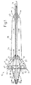
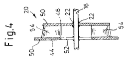
血液ポンプ10は、可撓性で曲げ自在であって、カテーテル14中に挿通する軸12を備える。カテーテル14は、約2mmの径の可撓性管で形成されている。カテーテル14は、好ましくは磨耗に耐性のあるポリマ製であり、ポリアミド又はポリウレタン等である。可撓性の軸12はカテーテル14中に挿通している。従来、軸は多列のワイヤ束で形成され、所望の場合、中央案内ワイヤ56を挿入する空洞を形成可能である。軸12は、例えば5000乃至15000rpmで図示しないモータにより近傍端を駆動され、一方で、カテーテル14は不動である。図1における遠位端、即ち左端には、軸12は硬質部分16を備える。カテーテル14の遠位端は、摺動ベアリング18を介して軸に接続されている。インペラ20は、蝶番22を介して軸12の硬質部分16に固定されており、インペラは軸12に対して折り畳めるようになしてある。インペラ20、並びに軸12及びカテーテル14の遠位部分は、エンベロープ24により囲まれている。エンベロープ24は、好ましくは袋状のポリウレタンスキン製である。ポリウレタンの材料特性により、エンベロープ24とカテーテル14とは良好に接続される。エンベロープ24の遠位端は、軸12の遠位端28を支持するハブ26を備える。軸は軸方向に移動することはできないが、ハブ26で回転するようになしてあり、エンベロープ24は、回転する軸12の回転に対して固定されている。
The
エンベロープ24はインペラ20の部分に環状の膨らみ30を備え、インペラ20は前記膨らみの中で回転する。エンベロープ24の遠位部分が膨らみ30を備えており、インペラ20はポンプヘッド31を形成している。膨らみ30の遠位部分に、エンベロープ24は同心状の平坦な壁32を備え、これはインペラ20の遠位側に対しわずかに距離をおいて設けてある。膨らみ30は、同心状に配置された弾性の棒34で補強され引き伸ばされている。棒34の遠位端は平坦な壁32に接続されている。棒34の近傍端はカテーテル14に接続されている。膨らみ30の近傍側では、エンベロープ24が長く延びる筒状延長部36を備える。筒状延長部36の外径は膨らみ30のそれより小さい。遠位及び近傍領域には、エンベロープ24が後方及び前方通流孔38、40を備えている。図1に示す実施形態において、前方通流孔38は入口開口であり、後方通流孔40は出口開口である。インペラ20の径方向外端とエンベロープ24との間には、環状の偏向チャネル42が血液ポンプの操作中に形成され、これを通して、偏向チャネルは血流を径方向に広げると共に、軸に向けて偏向する。
The
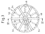
インペラ20は略平行な2つの支持壁44及び46を備え、これは、例えば蝶番22を介して軸12の硬質部分16と、2mmの間隔で恒久的に接続されている。各支持壁44、46は6つのスポーク48で画定されている。それぞれの隣り合うスポーク48間の角度は約60°である。スポーク48はポリマスキン(polymer skin)50で覆われたそれぞれのスポークホイールを画定している。スポーク48及びポリマスキン50はそれぞれの支持壁を画定している。2つの支持壁44、46の外輪郭は円形であり、約10mmの外径を有する。他に、図3に一点鎖線で示すように、スポーク48間の側壁の外縁は多角形辺を画定するように変形してもよい。前方の支持壁44のポリマスキン50は、軸12の硬質部分16を囲む円形の開口52を備える。開口52は約5mmの外径を有する。後方の支持壁46のポリマスキン50は、軸12の硬質部分16から支持壁46の径方向外端まで連続的に延長している。
The
支持壁44、46の間には、径方向のベーン54が、前方の支持壁44のポリマスキン50の部分に配設され、ベーンは支持壁44、46に直交している。ベーン54は、支持壁44、46の間に締結されたポリマスキンの羽根である。後方の支持壁46の半径は、前方の支持壁44の半径よりわずかに小さい。ポンプの操作条件では、前方の支持壁44は、エンベロープ24に対して約1mmのわずかな間隔で配設されている。後方の支持壁46の径方向外端は、エンベロープ24に対してより広い間隔で配置されている。よって、偏向チャネル42を血液が流れるように形成でき、一方、前方の支持壁44とエンベロープ24との間の約0.1mmのわずかな間隔により、比較的少量の血液が流れるのみである。よって、所望しない血液の逆流を避けられる。放射状に搬送するインペラ20の原理は、血液ポンプの構造状の許容範囲をより広くし、血液ポンプの調整不良を起こしにくくする。
Between the
図1に示す血液ポンプ10の第1の実施形態の操作条件では、略軸方向に配向される血流の血液は、エンベロープ24の前方通流孔38を通過し、血液ポンプ10に流れ込む。血流の主方向は図1に矢印で示してある。血液は、通流孔38から前方の支持壁44の開口52を通ってインペラ20に流れる。インペラ20は、図示しないモータにより駆動され回転する軸12により回転される。連続した後方の支持壁46は、流入して略軸方向に配向される血流を偏向し、これは、インペラ20内部での放射状の血流を形成し、放射状の血流はベーン54に向かう。そうするうちに、軸12の回転動作は、軸の硬質部分16から蝶番22を介してスポーク48に伝達され、最終的にベーン54に伝達される。
Under the operating conditions of the first embodiment of the
インペラ20の回転動作により、ベーン54は半径外側方向に血液を回転させる。半径外側に配向されたインペラ中の血流は、ベーン54の搬送作用により増加する。半径外側方向に回転した血液は、膨らみ30の領域のエンベロープ24の可撓性ポリマスキンに衝突し、エンベロープ24により偏向チャネル42を通じて配向される。偏向チャネル42の領域では、血流の放射状の主方向が軸12に向けて変更され、軸12に沿った軸方向に旋回する流れが生成される。エンベロープ24の平坦な壁32が前方の支持壁44に約0.1mmの間隔で近接しているという事実により、事実上、支持壁44と平坦な壁32との間を血液が逆流することはできない。
Due to the rotation of the
略漏斗状の膨らみ30は、インペラ20によりエンベロープ24の筒状延長部36中に血液を加速させる。筒状延長部36において、血流は再び軸方向に指向される。血液は、後方通流孔40を通じて血液ポンプ10から離れる。血液ポンプの実際の用途で得られる通常の流速は、約2乃至5リットル毎分である。この量を搬送するために、放射状ポンプは、約5000乃至15000rpmの比較的低速を要するのみである。本発明に係る放射状ポンプにおいて、血液へのダメージを大幅に避け得るように、血液が流れる領域の寸法を選ぶことが可能である。
The substantially funnel-shaped
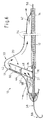
血流ポンプは、通常、左心室の大動脈を通じて血管内を前進する。このために、先ず、折り畳みにより、約10mmの血液ポンプの外径を縮めなくてはならない。血液ポンプの可撓性の構造により、図5に示すように簡便な折り畳みが可能である。ここで、矢印は、折り畳み工程での動きの方向を示している。例えば、カテーテル14を後端から軸12を越えて前方に動かし、軸12とカテーテル14とを相対的に移動させることにより、エンベロープ24及び棒34を介して軸12に向かってインペラ20を折り畳む。支持壁44、46は蝶番22で軸に対して折り畳まれ、スポーク48と可撓性ベーン54との間のポリマスキン50も一緒に折り畳まれる。スポーク48は軸12に対して折り畳まれ、後方の支持壁46のスポークは、前方の支持壁44のスポークに対してオフセットを有し、前方の支持壁44のスポーク間の空間において軸上に支承される。前方及び後方の支持壁のスポーク48のオフセット配置により、血液ポンプは、折り畳み状態で約3mmの小さい外径を有する。血液ポンプ10はこの折り畳み状態で血管内に挿入される。血液ポンプを皮膚及び組織を通して血管に挿入するために、カテーテル14は図示しない挿入管に内包されている。カテーテル14を挿入管に収めることで、血液ポンプ10を折り畳むこともできる。
A blood flow pump is usually advanced through the blood vessel through the aorta of the left ventricle. For this purpose, the outer diameter of the blood pump of about 10 mm must first be reduced by folding. Due to the flexible structure of the blood pump, simple folding is possible as shown in FIG. Here, the arrow has shown the direction of the movement in a folding process. For example, the
血液ポンプは以下のようにして広げる。血液ポンプ10を操作するために、軸12を図示しないモータによって回転させる。それにより遠心力を、軸12と共に回転するインペラ20に作用させる。この遠心力により、インペラ20は蝶番22を軸に広がる。インペラ20の径方向外端は内部からエンベロープ24を押し、自動的にこれを広げる。エンベロープ内部の圧力が周囲のそれより高いため、インペラ20によってエンベロープ24に向かって押された血液は、エンベロープ24の構造をたるみなく安定させる。説明した広げる方法の他に、インペラ20の支持構造48、22が超弾性金属の合金製であり、自ら広がるタイプで、後に回転により径方向に安定化される場合、蝶番22により能動的にインペラを広げることができる。
Spread the blood pump as follows. In order to operate the
図6は、血液ポンプ10の他の実施形態を示している。エンベロープ24は膨らみ30の領域に同心状の平坦な壁を有しない。インペラ20は、軸12を回転してポンプ10を動作するとき、軸12から径方向直角には展開しておらず、支持壁44、46と軸12とがテーパ角αをなすように展開している。角αは90°より小さい。ここではそれは約70°である。軸12及び軸の硬質部分16の回転中、インペラ20は、インペラに作用する遠心力により角αが動作状態の最大値になるまで持ち上がる。インペラ20の前方の支持壁44はエンベロープ24に押し付けられる。
FIG. 6 shows another embodiment of the
前方の支持壁44とエンベロープ24との間には、膨らみ30の領域でチャネル60が形成され、該チャネルは、チャネル60を通じての血液の逆流を最小限に保つためインペラ20の回転によって十分小さく保たれている。血液ポンプのポンプ動作は遠位端から近傍端まで効果的である。インペラ20の2つの支持壁44、46の傾斜位置により、軸12及びカテーテル14の相対移動によってインペラ20を折り畳むのが容易になる。図6は軸12を通じて延びる案内線56を示しており、該案内線の端58はJ字状であり、血液ポンプ10は前記案内線により心臓に挿入することができる。手術前に案内線56は除かれる。
Between the
図7は、血液ポンプ10の他の実施形態を示しており、図6の実施形態との違いは、インペラ20が軸に対して90°を越える角αで延びていることである。ここでは角αは約110°である。よって、血液は図6に比して血液ポンプ10の逆方向に流れる。ポンプ動作は、近傍端から遠位端まで効果的である。血液は、後方通流孔40を通じて血液ポンプ10に流れ、前方通流孔38を通じて血液ポンプ10から離れる。図7に示す実施形態においては、インペラ20は反対方向、即ち遠位、即ち図7に示す軸12の左の端に向けて折り畳まれる。インペラ20の折り畳み方向に応じて、血液ポンプ10は、前方向に、即ち図6に示すように遠位から近傍端へ、又は、例えば右心室をサポートするように、後方向に、即ち図7に示すように近傍から遠位端へ供給することができる。
FIG. 7 shows another embodiment of the
図8は血液ポンプ10の一実施形態を示しており、図6に示す血液ポンプに比して、隔壁62が、後方の支持壁46の直近傍に付加的に設けてある。隔壁62は、好ましくは、径方向内端がカテーテル14に恒久的に接続してあると共に、径方向外端がエンベロープ24に恒久的に接続してあるポリマスキン製である。偏向チャネル42の領域において、隔壁には、インペラ20のベーン54によって加速された血液が隔壁62近傍の領域に流れることができる通流孔64が設けてある。隔壁62とインペラ20の後方の支持壁46との間の低い位置には、インペラ近傍の領域の血液が、所望しない逆流を生じないように、付加チャネル60が形成されている。
FIG. 8 shows an embodiment of the
図9の上面図に示すように、インペラ20は2つの同一の支持壁44、46を備える。支持壁44、46は複数のスポーク48を備えるスポークホイールにより画定される。2つの支持壁44、46のスポーク48は合同である。複数のスポーク48の間にはポリマスキンは設けられていない。2つの支持壁44、46の合同なスポーク48の間には、羽根状のポリマスキンのベーン54が配してある。本実施形態の血液ポンプ10においては、第1の実施形態の後方の支持壁46のポリマスキン50の機能を、隔壁62が果たすようにしてある。よって、血液ポンプ10の構成的及び技術的機構は更に簡略化されている。ここでは、また、血液ポンプを血管内に容易に挿入できるように、血液ポンプ10の外径を減少させる目的で、インペラ20が、エンベロープ24と共に、軸12に対して折り畳めるようになしてある。
As shown in the top view of FIG. 9, the
軸12及びカテーテル14の相対移動による図6乃至8に示した血液ポンプの折り畳みは、例えば、カテーテル14中で軸12を後端から前方に動かすことで実施してよい。そうするうちに、エンベロープ24は伸び、軸12に向かって引っ張られる。インペラ20は、エンベロープ24によって軸12に向けて折り畳まれる。
The folding of the blood pump shown in FIGS. 6-8 by relative movement of the
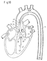
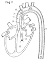
図10乃至12は、心臓内での血液ポンプの異なる配置方法を示している。 Figures 10 to 12 show different ways of placing the blood pump in the heart.
図10は、図1の第1の実施形態に係る血液ポンプ10を示している。血液ポンプ10は、遠位に配した通流孔38を備えるポンプヘッド31が左心室LVに位置すると共に、より近位に配した通流孔40を備えるポンプの後方領域が、大動脈弓AOBの前方の大動脈AOの内部に位置するように、配置してある。軸12を内包するカテーテル14は、大動脈AOを通じて延びており、大動脈弓AOBの領域で湾曲している。エンベロープ24の筒状延長部36は約60乃至80mmの長さを有する。大動脈弁AKは筒状延長部36を囲んでいる。血液ポンプ10は、遠位端から近位端への前方向、左心室LVから大動脈AO中へ血液を搬送する。血液は、遠位の通流孔38を通じて血液ポンプ10のエンベロープ24中へ流れる。回転するインペラは、エンベロープ24の膨らみ30内で血液を加速し、囲み24の筒状延長部36中に血液を押出す。血液は、遠位の通流孔40を通じて血液ポンプ10を離れる。
FIG. 10 shows a
図10は、「豚のしっぽ」の形状の硬質チップ26が延長し、その補助によって血液ポンプ10が心筋の位置で支持され、血液ポンプ10の吸引領域と心筋の内壁との間に最小の距離を保つ状態を示している。
FIG. 10 shows that a
図11は血液ポンプ10をより近位に配置する方法を示している。通流孔38を備える血液ポンプの遠位端は、心臓内部の左心室LVに位置している。より近位の通流孔40とインペラ20を含む膨らみ30とを備えるポンプヘッド31は大動脈弓AOBに対して遠位の大動脈AO内部に位置している。駆動軸12を内包するカテーテル14は大動脈弓AOBを通じて延びている。大動脈弓AOBの領域において可撓性軸12は湾曲している。大動脈弁AKは、搬送方向で示すように上流側に配した血液ポンプエンベロープ24の筒状延長部36を囲んでいる。筒状延長部36の長さは約60乃至80mmである。血液ポンプ10は、図10に示したのと同様の方式、即ち遠位端から近位端へ、左心室LVから大動脈AO内へ血液を搬送する。血液は、血液ポンプのエンベロープ24の筒状延長部36に入り、延長部は上流側に位置すると共に、図10に示したポンプに比して径方向に増強されており、遠位の通流孔38を通じて取り込み、エンベロープ24の膨らみ30内の図示しないインペラ20によって加速する。大動脈AO内部且つ大動脈弓AOBの前方において、加速された血液は前方の通流孔40を通じて流出する。
FIG. 11 illustrates a method of placing the
図12は、より長い筒状延長部36を備える血液ポンプ10の実施形態を示す。筒状延長部36は約200mmの長さを有する。遠位の通流孔38を備える血液ポンプ10の後端は心臓内の左心室LVに位置する。上流側の筒状延長部36は、大動脈弁AK及び大動脈弓AOBを通じて左心室LVから大動脈AO内に延びている。大動脈弓AOBの近傍に、前方の通流孔38を設けた膨らみ30内部に図示しないインペラ20を含むポンプヘッド31が位置している。左心室LV内で、血液は遠位の通流孔38を通じて血液ポンプ10に入り、上流の筒状延長部36及び大動脈弓AOBに取り込まれ、大動脈弓AOB近傍の位置で近位の通流孔40を通じて血液ポンプ10から離れる。図示しない駆動軸12を内包するカテーテル14は大動脈AO内に延びているが、大動脈弓AOBの湾曲部を通ることはない。本実施形態では軸12の湾曲はより少ない。よって、その湾曲により軸が破損する虞れは減少する。
FIG. 12 shows an embodiment of
Claims (14)
前記ロータは放射状に展開するインペラ(20)であり、
前記エンベロープ(24)は前記インペラ(12)の部分に環状の膨らみ(30)を有し、
前記ベーン(54)の径方向外端と囲い(24)との間には、径方向の流れを軸方向に偏向する環状の偏向チャネル(42)が形成してある
ことを特徴とする血液ポンプ。 A rotor provided with a vane (54), a flexible shaft (12) inserted through the catheter (14) to drive the impeller (20), and an envelope surrounding the impeller (20) ( 24) in a blood pump (10) that can be folded and inserted into a blood vessel,
The rotor is a radially expanding impeller (20);
The envelope (24) has an annular bulge (30) in the portion of the impeller (12),
An annular deflection channel (42) for deflecting the radial flow in the axial direction is formed between the radially outer end of the vane (54) and the enclosure (24). .
Applications Claiming Priority (2)
| Application Number | Priority Date | Filing Date | Title |
|---|---|---|---|
| DE102004054714A DE102004054714A1 (en) | 2004-11-12 | 2004-11-12 | Foldable intravascular insertable blood pump |
| PCT/EP2005/054804 WO2006051023A1 (en) | 2004-11-12 | 2005-09-26 | Folding, intravascularly inserted blood pump |
Publications (2)
| Publication Number | Publication Date |
|---|---|
| JP2008519624A true JP2008519624A (en) | 2008-06-12 |
| JP4553943B2 JP4553943B2 (en) | 2010-09-29 |
Family
ID=35385675
Family Applications (1)
| Application Number | Title | Priority Date | Filing Date |
|---|---|---|---|
| JP2007540619A Active JP4553943B2 (en) | 2004-11-12 | 2005-09-26 | Blood pump that can be folded and inserted into blood vessels |
Country Status (6)
| Country | Link |
|---|---|
| US (1) | US8814933B2 (en) |
| EP (1) | EP1827531B1 (en) |
| JP (1) | JP4553943B2 (en) |
| AU (1) | AU2005303859B2 (en) |
| DE (2) | DE102004054714A1 (en) |
| WO (1) | WO2006051023A1 (en) |
Cited By (10)
| Publication number | Priority date | Publication date | Assignee | Title |
|---|---|---|---|---|
| JP2015517334A (en) * | 2012-05-09 | 2015-06-22 | アビオメド オイローパ ゲーエムベーハー | Intravascular blood pump |
| JP2016052581A (en) * | 2011-08-29 | 2016-04-14 | ミネトロニクス, インコーポレイテッド | Expandable vas pump |
| WO2018139508A1 (en) * | 2017-01-27 | 2018-08-02 | テルモ株式会社 | Impeller and blood pump |
| JP2018525064A (en) * | 2015-06-23 | 2018-09-06 | アビオメド オイローパ ゲーエムベーハー | Blood pump |
| JPWO2018135477A1 (en) * | 2017-01-18 | 2019-11-07 | テルモ株式会社 | Blood pump |
| JP2019535366A (en) * | 2016-10-25 | 2019-12-12 | マジェンタ・メディカル・リミテッド | Ventricular assist device |
| JP2021058791A (en) * | 2014-05-13 | 2021-04-15 | アビオメド インコーポレイテッド | Cannula assembly |
| JP2021079139A (en) * | 2015-10-09 | 2021-05-27 | エーツェーペー エントヴィッケルングゲゼルシャフト エムベーハー | Pump, in particular blood pump |
| JP2022141796A (en) * | 2016-09-01 | 2022-09-29 | アビオメド インコーポレイテッド | Anti-suction blood pump inlet |
| JP7385839B2 (en) | 2019-03-14 | 2023-11-24 | アビオメド インコーポレイテッド | Blood flow measurement system |
Families Citing this family (106)
| Publication number | Priority date | Publication date | Assignee | Title |
|---|---|---|---|---|
| US6889082B2 (en) | 1997-10-09 | 2005-05-03 | Orqis Medical Corporation | Implantable heart assist system and method of applying same |
| DE10336902C5 (en) | 2003-08-08 | 2019-04-25 | Abiomed Europe Gmbh | Intracardiac pumping device |
| US7682301B2 (en) | 2003-09-18 | 2010-03-23 | Thoratec Corporation | Rotary blood pump |
| ES2421526T3 (en) * | 2004-08-13 | 2013-09-03 | Delgado Reynolds M Iii | Apparatus for long-term assistance of a left ventricle to pump blood |
| US7393181B2 (en) * | 2004-09-17 | 2008-07-01 | The Penn State Research Foundation | Expandable impeller pump |
| JP2009530041A (en) | 2006-03-23 | 2009-08-27 | ザ・ペン・ステート・リサーチ・ファンデーション | Cardiac assist device with expandable impeller pump |
| AU2007233078B2 (en) | 2006-03-31 | 2011-11-24 | Thoratec Corporation | Rotary blood pump |
| US9028392B2 (en) | 2006-12-01 | 2015-05-12 | NuCardia, Inc. | Medical device |
| US7828710B2 (en) * | 2007-06-05 | 2010-11-09 | Medical Value Partners, Llc | Apparatus comprising a drive cable for a medical device |
| US8079948B2 (en) | 2007-08-29 | 2011-12-20 | NuCardia, Inc. | Article comprising an impeller |
| ATE491483T1 (en) | 2007-10-08 | 2011-01-15 | Ais Gmbh Aachen Innovative Solutions | CATHETER DEVICE |
| US8489190B2 (en) | 2007-10-08 | 2013-07-16 | Ais Gmbh Aachen Innovative Solutions | Catheter device |
| ATE480274T1 (en) * | 2007-10-08 | 2010-09-15 | Ais Gmbh Aachen Innovative Sol | CATHETER DEVICE |
| US8439859B2 (en) | 2007-10-08 | 2013-05-14 | Ais Gmbh Aachen Innovative Solutions | Catheter device |
| AU2007362036B2 (en) * | 2007-12-07 | 2012-01-19 | NuCardia, Inc. | Medical device |
| EP2308422B1 (en) | 2008-06-23 | 2013-06-05 | Cardiobridge GmbH | Catheter pump for circulatory support |
| EP3050537A1 (en) | 2008-10-06 | 2016-08-03 | Indiana University Research and Technology Corporation | Methods and apparatus for active or passive assistance in the circulatory system |
| EP2194278A1 (en) | 2008-12-05 | 2010-06-09 | ECP Entwicklungsgesellschaft mbH | Fluid pump with a rotor |
| EP2216059A1 (en) | 2009-02-04 | 2010-08-11 | ECP Entwicklungsgesellschaft mbH | Catheter device with a catheter and an actuation device |
| EP2218469B1 (en) | 2009-02-12 | 2012-10-31 | ECP Entwicklungsgesellschaft mbH | Casing for a functional element |
| EP2248544A1 (en) * | 2009-05-05 | 2010-11-10 | ECP Entwicklungsgesellschaft mbH | Fluid pump with variable circumference, particularly for medical use |
| EP2266640A1 (en) | 2009-06-25 | 2010-12-29 | ECP Entwicklungsgesellschaft mbH | Compressible and expandable turbine blade for a fluid pump |
| CA2769631A1 (en) | 2009-07-01 | 2011-01-06 | The Penn State Research Foundation | Blood pump with expandable cannula |
| EP2298373A1 (en) * | 2009-09-22 | 2011-03-23 | ECP Entwicklungsgesellschaft mbH | Fluid pump with at least one turbine blade and a seating device |
| US8690749B1 (en) | 2009-11-02 | 2014-04-08 | Anthony Nunez | Wireless compressible heart pump |
| EP2338540A1 (en) * | 2009-12-23 | 2011-06-29 | ECP Entwicklungsgesellschaft mbH | Delivery blade for a compressible rotor |
| EP2338541A1 (en) | 2009-12-23 | 2011-06-29 | ECP Entwicklungsgesellschaft mbH | Radial compressible and expandable rotor for a fluid pump |
| EP2347778A1 (en) | 2010-01-25 | 2011-07-27 | ECP Entwicklungsgesellschaft mbH | Fluid pump with a radially compressible rotor |
| EP2388029A1 (en) | 2010-05-17 | 2011-11-23 | ECP Entwicklungsgesellschaft mbH | Pump array |
| EP2399639A1 (en) | 2010-06-25 | 2011-12-28 | ECP Entwicklungsgesellschaft mbH | System for introducing a pump |
| EP2407185A1 (en) | 2010-07-15 | 2012-01-18 | ECP Entwicklungsgesellschaft mbH | Radial compressible and expandable rotor for a pump with a turbine blade |
| EP2407186A1 (en) | 2010-07-15 | 2012-01-18 | ECP Entwicklungsgesellschaft mbH | Rotor for a pump, produced with an initial elastic material |
| US8597170B2 (en) | 2011-01-05 | 2013-12-03 | Thoratec Corporation | Catheter pump |
| US8485961B2 (en) | 2011-01-05 | 2013-07-16 | Thoratec Corporation | Impeller housing for percutaneous heart pump |
| US9138518B2 (en) | 2011-01-06 | 2015-09-22 | Thoratec Corporation | Percutaneous heart pump |
| WO2012094535A2 (en) | 2011-01-06 | 2012-07-12 | Thoratec Corporation | Percutaneous heart pump |
| US8734331B2 (en) | 2011-08-29 | 2014-05-27 | Minnetronix, Inc. | Expandable blood pumps and methods of their deployment and use |
| US8849398B2 (en) | 2011-08-29 | 2014-09-30 | Minnetronix, Inc. | Expandable blood pump for cardiac support |
| EP2606920A1 (en) | 2011-12-22 | 2013-06-26 | ECP Entwicklungsgesellschaft mbH | Sluice device for inserting a catheter |
| EP2606919A1 (en) | 2011-12-22 | 2013-06-26 | ECP Entwicklungsgesellschaft mbH | Sluice device for inserting a catheter |
| JP2015505515A (en) | 2012-02-07 | 2015-02-23 | フリダヤ インコーポレーテッドHridaya, Inc. | Blood circulation assist device |
| US11389638B2 (en) * | 2012-02-07 | 2022-07-19 | Hridaya, Inc. | Hemodynamic assist device |
| EP2830675A4 (en) | 2012-03-26 | 2016-01-27 | Procyrion Inc | Systems and methods for fluid flows and/or pressures for circulation and perfusion enhancement |
| US9327067B2 (en) | 2012-05-14 | 2016-05-03 | Thoratec Corporation | Impeller for catheter pump |
| DE102013008168A1 (en) | 2012-05-14 | 2013-11-14 | Thoratec Corporation | Impeller for catheter pump |
| US8721517B2 (en) | 2012-05-14 | 2014-05-13 | Thoratec Corporation | Impeller for catheter pump |
| US9446179B2 (en) | 2012-05-14 | 2016-09-20 | Thoratec Corporation | Distal bearing support |
| US9872947B2 (en) | 2012-05-14 | 2018-01-23 | Tc1 Llc | Sheath system for catheter pump |
| EP2858711B1 (en) | 2012-06-06 | 2018-03-07 | Magenta Medical Ltd. | Prosthetic renal valve |
| US9358329B2 (en) | 2012-07-03 | 2016-06-07 | Thoratec Corporation | Catheter pump |
| US9421311B2 (en) | 2012-07-03 | 2016-08-23 | Thoratec Corporation | Motor assembly for catheter pump |
| EP4186557A1 (en) | 2012-07-03 | 2023-05-31 | Tc1 Llc | Motor assembly for catheter pump |
| EP2745869A1 (en) | 2012-12-21 | 2014-06-25 | ECP Entwicklungsgesellschaft mbH | Sluice assembly for the introduction of a cord-like body, in particular of a catheter, into a patient |
| US10583231B2 (en) | 2013-03-13 | 2020-03-10 | Magenta Medical Ltd. | Blood pump |
| JP6530367B2 (en) | 2013-03-13 | 2019-06-12 | ティーシーワン エルエルシー | Fluid outlet / inlet system |
| US11033728B2 (en) | 2013-03-13 | 2021-06-15 | Tc1 Llc | Fluid handling system |
| US11077294B2 (en) | 2013-03-13 | 2021-08-03 | Tc1 Llc | Sheath assembly for catheter pump |
| EP2967361B1 (en) | 2013-03-13 | 2019-12-18 | Magenta Medical Ltd. | Renal pump |
| US9308302B2 (en) | 2013-03-15 | 2016-04-12 | Thoratec Corporation | Catheter pump assembly including a stator |
| EP2968742B1 (en) | 2013-03-15 | 2020-12-02 | Tc1 Llc | Catheter pump assembly including a stator |
| DE102013208038B4 (en) * | 2013-05-02 | 2016-09-08 | Michael Siegenthaler | Catheter-based cardiac assist system |
| US9764113B2 (en) | 2013-12-11 | 2017-09-19 | Magenta Medical Ltd | Curved catheter |
| WO2015160943A1 (en) | 2014-04-15 | 2015-10-22 | Thoratec Corporation | Sensors for catheter pumps |
| US10583232B2 (en) | 2014-04-15 | 2020-03-10 | Tc1 Llc | Catheter pump with off-set motor position |
| EP3479854A1 (en) | 2014-04-15 | 2019-05-08 | Tc1 Llc | Catheter pump with access ports |
| WO2015160990A1 (en) | 2014-04-15 | 2015-10-22 | Thoratec Corporation | Catheter pump introducer systems and methods |
| WO2016028644A1 (en) | 2014-08-18 | 2016-02-25 | Thoratec Corporation | Guide features for percutaneous catheter pump |
| US9675739B2 (en) | 2015-01-22 | 2017-06-13 | Tc1 Llc | Motor assembly with heat exchanger for catheter pump |
| EP3247420B1 (en) | 2015-01-22 | 2019-10-02 | Tc1 Llc | Reduced rotational mass motor assembly for catheter pump |
| WO2016118784A1 (en) | 2015-01-22 | 2016-07-28 | Thoratec Corporation | Attachment mechanisms for motor of catheter pump |
| DK3069740T3 (en) * | 2015-03-18 | 2021-01-25 | Abiomed Europe Gmbh | BLOOD PUMP |
| US10350341B2 (en) | 2015-03-20 | 2019-07-16 | Drexel University | Impellers, blood pumps, and methods of treating a subject |
| US9907890B2 (en) | 2015-04-16 | 2018-03-06 | Tc1 Llc | Catheter pump with positioning brace |
| US11291824B2 (en) | 2015-05-18 | 2022-04-05 | Magenta Medical Ltd. | Blood pump |
| EP3804804A1 (en) | 2016-07-21 | 2021-04-14 | Tc1 Llc | Fluid seals for catheter pump motor assembly |
| EP3487550B1 (en) | 2016-07-21 | 2022-09-28 | Tc1 Llc | Gas-filled chamber for catheter pump motor assembly |
| EP3518825B1 (en) | 2016-09-29 | 2020-05-27 | Magenta Medical Ltd. | Blood vessel tube |
| WO2018067410A1 (en) | 2016-10-03 | 2018-04-12 | Queen Mary University Of London | Mechanical circulatory support device with axial flow turbomachine optimized for heart failure and cardio-renal syndrome |
| AU2017364359B2 (en) | 2016-11-23 | 2022-12-01 | Magenta Medical Ltd. | Blood pumps |
| EP3630218A4 (en) | 2017-06-01 | 2021-05-12 | Queen Mary University of London | Mechanical circulatory support device with centrifugal impeller designed for implantation in the descending aorta |
| JP7414529B2 (en) | 2017-06-07 | 2024-01-16 | シファメド・ホールディングス・エルエルシー | Intravascular fluid transfer devices, systems, and methods of use |
| WO2019015740A1 (en) * | 2017-07-17 | 2019-01-24 | Griesmühle Kleinkraftwerk Gmbh | Device and method for the comminution of circulating tumour cell clusters |
| ES2896901T3 (en) | 2017-08-23 | 2022-02-28 | Ecp Entw Mbh | Drive shaft cover with a heat-conducting part |
| JP7319266B2 (en) | 2017-11-13 | 2023-08-01 | シファメド・ホールディングス・エルエルシー | Intravascular fluid transfer devices, systems and methods of use |
| US10905808B2 (en) | 2018-01-10 | 2021-02-02 | Magenta Medical Ltd. | Drive cable for use with a blood pump |
| EP3638336B1 (en) | 2018-01-10 | 2022-04-06 | Magenta Medical Ltd. | Ventricular assist device |
| DE102018201030A1 (en) | 2018-01-24 | 2019-07-25 | Kardion Gmbh | Magnetic coupling element with magnetic bearing function |
| CN117959583A (en) | 2018-02-01 | 2024-05-03 | 施菲姆德控股有限责任公司 | Intravascular blood pump and methods of use and manufacture |
| US10893927B2 (en) | 2018-03-29 | 2021-01-19 | Magenta Medical Ltd. | Inferior vena cava blood-flow implant |
| WO2019195480A1 (en) | 2018-04-04 | 2019-10-10 | Theodosios Korakianitis | Removable mechanical circulatory support for short term use |
| US11690997B2 (en) | 2018-04-06 | 2023-07-04 | Puzzle Medical Devices Inc. | Mammalian body conduit intralumenal device and lumen wall anchor assembly, components thereof and methods of implantation and explanation thereof |
| AT521414B1 (en) * | 2018-06-18 | 2021-01-15 | Mohl Werner | Stent pump |
| DE102018211327A1 (en) | 2018-07-10 | 2020-01-16 | Kardion Gmbh | Impeller for an implantable vascular support system |
| US11541224B2 (en) * | 2018-07-30 | 2023-01-03 | Cardiovascular Systems, Inc. | Intravascular pump without inducer and centrifugal force-driven expansion of impeller blades and/or expandable and collapsible impeller housing |
| CN113543836A (en) | 2019-01-24 | 2021-10-22 | 马真塔医药有限公司 | Ventricular assist device |
| EP3996797A4 (en) | 2019-07-12 | 2023-08-02 | Shifamed Holdings, LLC | Intravascular blood pumps and methods of manufacture and use |
| WO2021016372A1 (en) | 2019-07-22 | 2021-01-28 | Shifamed Holdings, Llc | Intravascular blood pumps with struts and methods of use and manufacture |
| US11730946B2 (en) * | 2019-08-12 | 2023-08-22 | Boston Scientific Scimed, Inc. | Flow enhancement for circulatory support device |
| US11724089B2 (en) | 2019-09-25 | 2023-08-15 | Shifamed Holdings, Llc | Intravascular blood pump systems and methods of use and control thereof |
| IL293625A (en) | 2019-12-03 | 2022-08-01 | Procyrion Inc | Blood pumps |
| CN115279451A (en) | 2019-12-13 | 2022-11-01 | 普罗西里翁公司 | Support structure for intravascular blood pump |
| AU2021207811A1 (en) * | 2020-01-14 | 2022-09-08 | Abiomed, Inc. | Intravascular blood pump with outflow hose |
| DE102020102474A1 (en) | 2020-01-31 | 2021-08-05 | Kardion Gmbh | Pump for conveying a fluid and method for manufacturing a pump |
| USD1029236S1 (en) | 2022-08-12 | 2024-05-28 | Luminoah, Inc. | Fluid pouch assembly |
| USD1029235S1 (en) | 2022-08-12 | 2024-05-28 | Luminoah, Inc. | Fluid delivery system |
| CN116870356A (en) * | 2023-06-28 | 2023-10-13 | 安徽通灵仿生科技有限公司 | Catheter pump assembly and control system thereof |
Citations (4)
| Publication number | Priority date | Publication date | Assignee | Title |
|---|---|---|---|---|
| JPH02203867A (en) * | 1988-10-13 | 1990-08-13 | Kensey Nash Corp | Feed catheter for blood pump of intra-aortic location type and using method therefor |
| JPH08500512A (en) * | 1992-09-02 | 1996-01-23 | レイタン,オイビンド | Catheter pump |
| JP2001515375A (en) * | 1996-04-04 | 2001-09-18 | インペラ カーディオテヒニック ゲゼルシャフト ミット ベシュレンクター ハフツング | Intravascular blood pump |
| JP2003504091A (en) * | 1998-03-07 | 2003-02-04 | シュミッツ−ローデ、トーマス | Intravascular self-deploying axial flow pump for temporary cardiac support |
Family Cites Families (3)
| Publication number | Priority date | Publication date | Assignee | Title |
|---|---|---|---|---|
| US4753221A (en) * | 1986-10-22 | 1988-06-28 | Intravascular Surgical Instruments, Inc. | Blood pumping catheter and method of use |
| US5827171A (en) * | 1996-10-31 | 1998-10-27 | Momentum Medical, Inc. | Intravascular circulatory assist device |
| US6217541B1 (en) * | 1999-01-19 | 2001-04-17 | Kriton Medical, Inc. | Blood pump using cross-flow principles |
-
2004
- 2004-11-12 DE DE102004054714A patent/DE102004054714A1/en not_active Withdrawn
-
2005
- 2005-09-26 DE DE502005009922T patent/DE502005009922D1/en active Active
- 2005-09-26 US US11/667,258 patent/US8814933B2/en active Active
- 2005-09-26 AU AU2005303859A patent/AU2005303859B2/en active Active
- 2005-09-26 EP EP05789513A patent/EP1827531B1/en active Active
- 2005-09-26 WO PCT/EP2005/054804 patent/WO2006051023A1/en active Application Filing
- 2005-09-26 JP JP2007540619A patent/JP4553943B2/en active Active
Patent Citations (4)
| Publication number | Priority date | Publication date | Assignee | Title |
|---|---|---|---|---|
| JPH02203867A (en) * | 1988-10-13 | 1990-08-13 | Kensey Nash Corp | Feed catheter for blood pump of intra-aortic location type and using method therefor |
| JPH08500512A (en) * | 1992-09-02 | 1996-01-23 | レイタン,オイビンド | Catheter pump |
| JP2001515375A (en) * | 1996-04-04 | 2001-09-18 | インペラ カーディオテヒニック ゲゼルシャフト ミット ベシュレンクター ハフツング | Intravascular blood pump |
| JP2003504091A (en) * | 1998-03-07 | 2003-02-04 | シュミッツ−ローデ、トーマス | Intravascular self-deploying axial flow pump for temporary cardiac support |
Cited By (21)
| Publication number | Priority date | Publication date | Assignee | Title |
|---|---|---|---|---|
| JP2016052581A (en) * | 2011-08-29 | 2016-04-14 | ミネトロニクス, インコーポレイテッド | Expandable vas pump |
| JP2017094191A (en) * | 2011-08-29 | 2017-06-01 | ミネトロニクス, インコーポレイテッド | Expandable vascular pump |
| JP2017196495A (en) * | 2012-05-09 | 2017-11-02 | アビオメド オイローパ ゲーエムベーハー | Intravascular blood pump |
| JP2015517334A (en) * | 2012-05-09 | 2015-06-22 | アビオメド オイローパ ゲーエムベーハー | Intravascular blood pump |
| JP2021058791A (en) * | 2014-05-13 | 2021-04-15 | アビオメド インコーポレイテッド | Cannula assembly |
| JP7086237B2 (en) | 2014-05-13 | 2022-06-17 | アビオメド インコーポレイテッド | Cannula assembly |
| JP2018525064A (en) * | 2015-06-23 | 2018-09-06 | アビオメド オイローパ ゲーエムベーハー | Blood pump |
| JP2021079139A (en) * | 2015-10-09 | 2021-05-27 | エーツェーペー エントヴィッケルングゲゼルシャフト エムベーハー | Pump, in particular blood pump |
| JP7171794B2 (en) | 2015-10-09 | 2022-11-15 | エーツェーペー エントヴィッケルングゲゼルシャフト エムベーハー | pumps, especially blood pumps |
| US11793997B2 (en) | 2015-10-09 | 2023-10-24 | Ecp Entwicklungsgesellschaft Mbh | Pump, in particular a blood pump |
| US11938311B2 (en) | 2016-09-01 | 2024-03-26 | Abiomed, Inc. | Anti-suction blood pump inlet |
| JP2022141796A (en) * | 2016-09-01 | 2022-09-29 | アビオメド インコーポレイテッド | Anti-suction blood pump inlet |
| JP7405914B2 (en) | 2016-09-01 | 2023-12-26 | アビオメド インコーポレイテッド | Anti-stick blood pump inlet |
| JP7383476B2 (en) | 2016-10-25 | 2023-11-20 | マジェンタ・メディカル・リミテッド | ventricular assist device |
| JP2019535366A (en) * | 2016-10-25 | 2019-12-12 | マジェンタ・メディカル・リミテッド | Ventricular assist device |
| JPWO2018135477A1 (en) * | 2017-01-18 | 2019-11-07 | テルモ株式会社 | Blood pump |
| JP7150615B2 (en) | 2017-01-18 | 2022-10-11 | テルモ株式会社 | blood pump |
| WO2018139508A1 (en) * | 2017-01-27 | 2018-08-02 | テルモ株式会社 | Impeller and blood pump |
| JP7150617B2 (en) | 2017-01-27 | 2022-10-11 | テルモ株式会社 | impeller and blood pump |
| JPWO2018139508A1 (en) * | 2017-01-27 | 2019-11-21 | テルモ株式会社 | Impeller and blood pump |
| JP7385839B2 (en) | 2019-03-14 | 2023-11-24 | アビオメド インコーポレイテッド | Blood flow measurement system |
Also Published As
| Publication number | Publication date |
|---|---|
| AU2005303859B2 (en) | 2011-11-03 |
| JP4553943B2 (en) | 2010-09-29 |
| DE502005009922D1 (en) | 2010-08-26 |
| DE102004054714A1 (en) | 2006-05-24 |
| EP1827531A1 (en) | 2007-09-05 |
| US8814933B2 (en) | 2014-08-26 |
| AU2005303859A1 (en) | 2006-05-18 |
| US20080103591A1 (en) | 2008-05-01 |
| WO2006051023A1 (en) | 2006-05-18 |
| EP1827531B1 (en) | 2010-07-14 |
Similar Documents
| Publication | Publication Date | Title |
|---|---|---|
| JP4553943B2 (en) | Blood pump that can be folded and inserted into blood vessels | |
| JP6360948B2 (en) | Intravascular blood pump | |
| US11280345B2 (en) | Pump housing with an interior for accommodating a pump rotor | |
| KR102664788B1 (en) | blood pump | |
| US4753221A (en) | Blood pumping catheter and method of use | |
| JP5112520B2 (en) | Medical equipment | |
| JP7150615B2 (en) | blood pump | |
| JP5815516B2 (en) | Blood pump with expandable cannula | |
| JP7150617B2 (en) | impeller and blood pump | |
| US8371997B2 (en) | Article comprising an impeller II | |
| JP2020507368A (en) | Catheter pump with pump head for introduction into arterial blood vessels | |
| US20210213273A1 (en) | Intravascular Blood Pump with Outflow Hose | |
| CN114733062A (en) | Ventricular assist device | |
| CN219251393U (en) | Catheter pump and stent thereof | |
| CN219251392U (en) | Catheter pump support and catheter pump | |
| KR20240067978A (en) | Blood pump |
Legal Events
| Date | Code | Title | Description |
|---|---|---|---|
| A131 | Notification of reasons for refusal |
Free format text: JAPANESE INTERMEDIATE CODE: A131 Effective date: 20090825 |
|
| A977 | Report on retrieval |
Free format text: JAPANESE INTERMEDIATE CODE: A971007 Effective date: 20090827 |
|
| A131 | Notification of reasons for refusal |
Free format text: JAPANESE INTERMEDIATE CODE: A131 Effective date: 20100302 |
|
| A521 | Request for written amendment filed |
Free format text: JAPANESE INTERMEDIATE CODE: A523 Effective date: 20100527 |
|
| TRDD | Decision of grant or rejection written | ||
| A01 | Written decision to grant a patent or to grant a registration (utility model) |
Free format text: JAPANESE INTERMEDIATE CODE: A01 Effective date: 20100622 |
|
| A01 | Written decision to grant a patent or to grant a registration (utility model) |
Free format text: JAPANESE INTERMEDIATE CODE: A01 |
|
| A61 | First payment of annual fees (during grant procedure) |
Free format text: JAPANESE INTERMEDIATE CODE: A61 Effective date: 20100713 |
|
| FPAY | Renewal fee payment (event date is renewal date of database) |
Free format text: PAYMENT UNTIL: 20130723 Year of fee payment: 3 |
|
| R150 | Certificate of patent or registration of utility model |
Ref document number: 4553943 Country of ref document: JP Free format text: JAPANESE INTERMEDIATE CODE: R150 Free format text: JAPANESE INTERMEDIATE CODE: R150 |
|
| R250 | Receipt of annual fees |
Free format text: JAPANESE INTERMEDIATE CODE: R250 |
|
| R250 | Receipt of annual fees |
Free format text: JAPANESE INTERMEDIATE CODE: R250 |
|
| R250 | Receipt of annual fees |
Free format text: JAPANESE INTERMEDIATE CODE: R250 |
|
| R250 | Receipt of annual fees |
Free format text: JAPANESE INTERMEDIATE CODE: R250 |
|
| R250 | Receipt of annual fees |
Free format text: JAPANESE INTERMEDIATE CODE: R250 |
|
| R250 | Receipt of annual fees |
Free format text: JAPANESE INTERMEDIATE CODE: R250 |
|
| R250 | Receipt of annual fees |
Free format text: JAPANESE INTERMEDIATE CODE: R250 |
|
| R250 | Receipt of annual fees |
Free format text: JAPANESE INTERMEDIATE CODE: R250 |
|
| R250 | Receipt of annual fees |
Free format text: JAPANESE INTERMEDIATE CODE: R250 |
|
| R250 | Receipt of annual fees |
Free format text: JAPANESE INTERMEDIATE CODE: R250 |
|
| R250 | Receipt of annual fees |
Free format text: JAPANESE INTERMEDIATE CODE: R250 |