JP2008021226A - Sales data processing device and program - Google Patents

Sales data processing device and program Download PDF

Info

Publication number
JP2008021226A
JP2008021226A JP2006194130A JP2006194130A JP2008021226A JP 2008021226 A JP2008021226 A JP 2008021226A JP 2006194130 A JP2006194130 A JP 2006194130A JP 2006194130 A JP2006194130 A JP 2006194130A JP 2008021226 A JP2008021226 A JP 2008021226A
Authority
JP
Japan
Prior art keywords
product
data
sales data
information
tag
Prior art date
Legal status (The legal status is an assumption and is not a legal conclusion. Google has not performed a legal analysis and makes no representation as to the accuracy of the status listed.)
Pending
Application number
JP2006194130A
Other languages
Japanese (ja)
Other versions
JP2008021226A5 (en
Inventor
Tsuneaki Hashimoto
庸明 橋本
Current Assignee (The listed assignees may be inaccurate. Google has not performed a legal analysis and makes no representation or warranty as to the accuracy of the list.)
Casio Computer Co Ltd
Original Assignee
Casio Computer Co Ltd
Priority date (The priority date is an assumption and is not a legal conclusion. Google has not performed a legal analysis and makes no representation as to the accuracy of the date listed.)
Filing date
Publication date
Application filed by Casio Computer Co Ltd filed Critical Casio Computer Co Ltd
Priority to JP2006194130A priority Critical patent/JP2008021226A/en
Publication of JP2008021226A publication Critical patent/JP2008021226A/en
Publication of JP2008021226A5 publication Critical patent/JP2008021226A5/ja
Pending legal-status Critical Current

Links

Images

Landscapes

  • Cash Registers Or Receiving Machines (AREA)

Abstract

<P>PROBLEM TO BE SOLVED: To provide a sales data processing device capable of easily subtracting sales data for returned commodities by utilizing a storage means such as an IC tag provided in an individual commodity and easily discriminating whether or not a commodity whose payment has been already made, that is, or not a purchased commodity. <P>SOLUTION: According to this sales data processing system 100, in an entrance terminal 2, an IC tag reader 28 reads IC tag data of an IC tag provided in a commodity brought in by a customer, and when purchase date information is read as IC tag data together with commodity identification information as the IC tag data, these pieces of information are transmitted together with a customer number of the customer to an exit terminal 3. The output terminal 3 subtracts sales data of a commodity corresponding to commodity identification information of return object data received from the input terminal 2 from a sales total by commodities memory 331. <P>COPYRIGHT: (C)2008,JPO&INPIT

Description

本発明は、商品に設けられたICタグ等の記憶手段に記憶された商品識別情報に基づいて売上データ処理を行う売上データ処理装置及びプログラムに関する。   The present invention relates to a sales data processing apparatus and program for performing sales data processing based on product identification information stored in storage means such as an IC tag provided for a product.

従来、商品に商品識別情報を記憶したICタグを取り付けておき、ICタグに記憶された商品識別情報を読み取って、読み取った商品識別情報に基づき購入された商品の支払いを行うシステムが提案されている。   Conventionally, a system has been proposed in which an IC tag storing product identification information is attached to a product, the product identification information stored in the IC tag is read, and the purchased product is paid based on the read product identification information. Yes.

例えば、特許文献1には、商品に商品識別情報を記憶したICタグを取り付けておき、ICタグ読み取り機能付き移動体通信機器により購入する商品に取り付けられたICタグの商品情報を読み取って、読み取られた商品情報と移動体通信機器の電話番号とをPOS端末に送信し、購入商品代金の支払い処理を行う技術が記載されている。
特開2005−92313号公報
For example, in Patent Document 1, an IC tag storing product identification information is attached to a product, and the product information of the IC tag attached to the product purchased by the mobile communication device with the IC tag reading function is read and read. A technique is described in which the received merchandise information and the telephone number of the mobile communication device are transmitted to the POS terminal and the purchase merchandise price is paid.
JP 2005-92313 A

しかしながら、特許文献1に記載の技術においては、支払い後に生じた返品には対応することができないという問題があった。   However, the technique described in Patent Document 1 has a problem that it cannot respond to returned goods generated after payment.

本発明の課題は、個々の商品に設けられたICタグ等の記憶手段を利用して、既に購入済みの商品であるか否かを容易に識別可能とし、返品商品に対する売上データの減算を容易に行えるようにすることである。   An object of the present invention is to make it possible to easily identify whether or not a product has already been purchased by using a storage means such as an IC tag provided for each product, and to easily subtract sales data from returned products. Is to be able to do it.

上記課題を解決するため、請求項1に記載の発明は、
取引対象の商品に設けられ当該商品の商品識別情報を含む情報を記憶する記憶手段に記憶された情報を読み取って前記商品識別情報を含む情報を受信する受信手段と、
前記受信手段により受信された商品識別情報に対応する商品の売上データの累計を行う売上データ処理手段と、
取引により購入された商品に設けられている前記記憶手段に、当該商品が購入済みであることを示す情報を書き込む書き込み手段と、
前記受信手段により、前記商品識別情報とともに前記購入済みであることを示す情報が受信された場合に、前記受信された商品識別情報に対応する商品の売上データを減算する売上データ減算手段と、
前記売上データを減算した商品に関する情報をレシート上に印刷出力する出力手段と、
を備えたことを特徴としている。
In order to solve the above-mentioned problem, the invention described in claim 1
Receiving means for receiving information including the product identification information by reading information stored in a storage means for storing information including the product identification information of the product provided for the product to be traded;
Sales data processing means for accumulating sales data of products corresponding to the product identification information received by the receiving means;
A writing unit for writing information indicating that the product has been purchased into the storage unit provided for the product purchased by the transaction;
Sales data subtracting means for subtracting sales data of the product corresponding to the received product identification information when the receiving unit receives information indicating that the product has been purchased together with the product identification information;
An output means for printing out information on the product obtained by subtracting the sales data on a receipt;
It is characterized by having.

請求項4に記載の発明は、
コンピュータを、
取引対象の商品に設けられ当該商品の商品識別情報を含む情報を記憶する記憶手段に記憶された情報を読み取って前記商品識別情報を含む情報を受信する受信手段、
前記受信手段により受信された商品識別情報に対応する商品の売上データの累計を行う売上データ処理手段、
取引により購入された商品に設けられている前記記憶手段に、当該商品が購入済みであることを示す情報を書き込む書き込み手段、
前記受信手段により、前記商品識別情報とともに前記購入済みであることを示す情報が受信された場合に、前記受信された商品識別情報に対応する商品の売上データを減算する売上データ減算手段、
前記売上データを減算した商品に関する情報をレシート上に印刷出力する出力手段、
として機能させるためのプログラムであることを特徴としている。
The invention according to claim 4
Computer
Receiving means for receiving information including the product identification information by reading information stored in a storage means for storing information including the product identification information of the product that is provided in the product to be traded;
Sales data processing means for accumulating sales data of products corresponding to the product identification information received by the receiving means;
A writing unit for writing information indicating that the product has been purchased into the storage unit provided for the product purchased by the transaction;
Sales data subtracting means for subtracting sales data of a product corresponding to the received product identification information when the receiving unit receives information indicating that the purchase has been completed together with the product identification information.
Output means for printing out information on a product obtained by subtracting the sales data on a receipt;
It is a program for making it function as.

請求項1、4に記載の発明によれば、取引対象の商品に設けられ当該商品の商品識別情報を含む情報を記憶する記憶手段に記憶された情報を受信し、受信した商品識別情報に対応する商品の売上データの累計を行うとともに、取引により購入された商品に設けられている記憶手段に、当該商品が購入済みであることを示す情報を書き込む。そして、商品識別情報とともに購入済みであることを示す情報が受信された場合に、受信された商品識別情報に対応する商品の売上データを減算し、売上データを減算した商品に関する情報をレシート上に印刷出力する。   According to the first and fourth aspects of the present invention, the information stored in the storage means for storing information including the product identification information of the product provided for the transaction is received, and the received product identification information is supported. The sales data of the products to be accumulated is accumulated, and information indicating that the products have been purchased is written in the storage means provided for the products purchased by the transaction. Then, when information indicating that the product has been purchased is received together with the product identification information, the sales data of the product corresponding to the received product identification information is subtracted, and information on the product obtained by subtracting the sales data is displayed on the receipt. Print out.

従って、商品に設けられた記憶手段の内容に基づいて、返品商品に対する売上データの減算を容易に行うことが可能となる。また、返品商品に対する売上データの減算結果をレシート上に印刷出力することが可能となる。   Therefore, it is possible to easily subtract sales data for returned merchandise based on the contents of the storage means provided for the merchandise. In addition, the result of subtracting the sales data for the returned merchandise can be printed out on the receipt.

請求項2に記載の発明によれば、減算した売上データの合計をレシート上に印刷することが可能となる。   According to the invention described in claim 2, it is possible to print the total of the subtracted sales data on the receipt.

請求項3に記載の発明によれば、購入日付から所定日数以上経過している商品については売上データの減算を行わないので、購入してから所定日数以上経った商品の返品を防止することができる。   According to the invention described in claim 3, since the sales data is not subtracted for a product that has passed a predetermined number of days from the purchase date, it is possible to prevent the return of the product that has passed the predetermined number of days since the purchase. it can.

以下、図を参照して本発明の実施形態について説明する。
まず、構成を説明する。
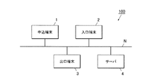
図1に、本発明に係る売上データ処理システム100の全体構成を示す。売上データ処理システム100は、店舗内に設置されるシステムであり、図1に示すように、申込端末1、入口端末2、出口端末3、サーバ4が通信ネットワークNを介してデータ送受信可能に接続されて構成されている。
Hereinafter, embodiments of the present invention will be described with reference to the drawings.
First, the configuration will be described.
FIG. 1 shows the overall configuration of a sales data processing system 100 according to the present invention. The sales data processing system 100 is a system installed in a store. As shown in FIG. 1, the application terminal 1, the entrance terminal 2, the exit terminal 3, and the server 4 are connected via a communication network N so that data can be transmitted and received. Has been configured.

〔申込端末1の構成〕
図2に、申込端末1の機能構成例を示す。申込端末1は、店舗の入口付近に設置され、当該店舗を利用する顧客の顧客登録を行って、登録された顧客に対し顧客用ICカードを発行するための端末であり、図2に示すように、CPU11、入力装置12、RAM13、伝送制御部14、表示装置15、記録装置16、ICカード発行装置17を備えて構成され、各部はバス18を介して接続されている。
[Configuration of application terminal 1]
FIG. 2 shows a functional configuration example of the application terminal 1. The application terminal 1 is a terminal that is installed near the entrance of a store, performs customer registration of a customer who uses the store, and issues a customer IC card to the registered customer, as shown in FIG. And a CPU 11, an input device 12, a RAM 13, a transmission control unit 14, a display device 15, a recording device 16, and an IC card issuing device 17, and each unit is connected via a bus 18.

CPU(Central Processing Unit)11は、記録装置16に記憶されているシステムプログラムを読み出し、RAM13内に形成されたワークエリアに展開し、該システムプログラムに従って各部を制御する。また、CPU11は、記録装置16に記憶されている顧客登録処理プログラムを始めとする各種処理プログラムを読み出してワークエリアに展開し、後述する顧客登録処理(図12参照)を始めとする各種処理を実行する。   A CPU (Central Processing Unit) 11 reads a system program stored in the recording device 16, develops it in a work area formed in the RAM 13, and controls each unit according to the system program. Further, the CPU 11 reads out various processing programs including a customer registration processing program stored in the recording device 16 and develops them in a work area, and performs various processing including customer registration processing (see FIG. 12) described later. Execute.

入力装置12は、カーソルキー、数字入力キー、及び各種機能キー等を備えたキーボードと、マウス等のポインティングデバイスを備えて構成され、キーボードで押下操作されたキーの押下信号とマウスによる操作信号とを、入力信号としてCPU11に出力する。なお、入力装置12は、表示装置15の表示画面を覆う透明なシートパネルに、指又は専用のスタイラスペンで触れることにより入力される位置情報を入力情報としてCPU11へ出力する、タッチパネルにより構成されるようにしてもよい。   The input device 12 includes a keyboard having cursor keys, numeric input keys, various function keys, and the like, and a pointing device such as a mouse, and includes a key pressing signal pressed by the keyboard and an operation signal by the mouse. To the CPU 11 as an input signal. The input device 12 includes a touch panel that outputs position information input by touching a transparent sheet panel covering the display screen of the display device 15 with a finger or a dedicated stylus pen as input information to the CPU 11. You may do it.

RAM(Random Access Memory)13は、CPU11により実行されるシステムプログラム、各種処理プログラム、各処理において処理中のデータ、処理結果などを一時的に記憶するワークエリアを形成する。   A RAM (Random Access Memory) 13 forms a work area for temporarily storing a system program executed by the CPU 11, various processing programs, data being processed in each processing, processing results, and the like.

伝送制御部14は、NIC(Network Interface Card)、ルータ等の通信インターフェースを備えて構成され、通信ネットワークNに接続された各装置とデータ送受信を行う。   The transmission control unit 14 includes a communication interface such as a NIC (Network Interface Card) and a router, and performs data transmission / reception with each device connected to the communication network N.

表示装置15は、CRT(Cathode Ray Tube)やLCD(Liquid Crystal Display)等のモニタを備えて構成されており、CPU11から入力される表示信号の指示に従って、各種画面を表示する。   The display device 15 includes a monitor such as a CRT (Cathode Ray Tube) or an LCD (Liquid Crystal Display), and displays various screens according to instructions of display signals input from the CPU 11.

記録装置16は、磁気的又は光学的記録媒体若しくは不揮発性の半導体メモリ等により構成され、CPU11で実行されるシステムプログラム、当該システムプログラムに対応する、顧客登録処理プログラムを始めとする各種処理プログラム、各種データ等を記憶する。これらの各種プログラムは、読取可能なプログラムコードの形態で格納され、CPU11は、当該プログラムコードに従った動作を逐次実行する。   The recording device 16 is composed of a magnetic or optical recording medium, a nonvolatile semiconductor memory, or the like, and is a system program executed by the CPU 11, various processing programs including a customer registration processing program corresponding to the system program, Stores various data. These various programs are stored in the form of readable program codes, and the CPU 11 sequentially executes operations according to the program codes.

ICカード発行装置17は、CPU11からの指示に従って、顧客番号、顧客の個人データ、支払い情報等のデータをICカードに書き込んで顧客用ICカードを発行する。   The IC card issuing device 17 writes data such as a customer number, customer personal data, and payment information on the IC card in accordance with an instruction from the CPU 11 and issues a customer IC card.

〔入口端末2の構成〕
図3に、入口端末2の機能構成例を示す。入口端末2は、店舗の入口付近に設置され、入店した人物が登録された顧客であるか否かのチェックを行うための端末であり、図2に示すように、CPU21、人検知センサ22、RAM23、伝送制御部24、音声出力装置25、記録装置26、ICカードリーダ27、ICタグリーダ28、入口ゲート開閉装置29を備えて構成され、各部はバス210を介して接続されている。
[Configuration of entrance terminal 2]
FIG. 3 shows a functional configuration example of the entrance terminal 2. The entrance terminal 2 is a terminal installed near the entrance of the store, and is a terminal for checking whether or not the person who entered the store is a registered customer. As shown in FIG. 2, as shown in FIG. , RAM 23, transmission control unit 24, audio output device 25, recording device 26, IC card reader 27, IC tag reader 28, and entrance gate opening / closing device 29, which are connected via a bus 210.

CPU21は、記録装置26に記憶されているシステムプログラムを読み出し、RAM23内に形成されたワークエリアに展開し、該システムプログラムに従って各部を制御する。また、CPU21は、記録装置26に記憶されている入口処理プログラムを始めとする各種処理プログラムを読み出してワークエリアに展開し、後述する入口処理(図13参照)を始めとする各種処理を実行する。   The CPU 21 reads a system program stored in the recording device 26, develops it in a work area formed in the RAM 23, and controls each unit according to the system program. Further, the CPU 21 reads out various processing programs including the entrance processing program stored in the recording device 26, develops them in the work area, and executes various processing including entrance processing (see FIG. 13) described later. .

人検知センサ22は、例えば、焦電型赤外線センサであり、入店した人物を検知して検知信号をCPU21に出力する。   The human detection sensor 22 is, for example, a pyroelectric infrared sensor, detects a person who has entered the store, and outputs a detection signal to the CPU 21.

RAM23は、CPU21により実行されるシステムプログラム、各種処理プログラム、各処理において処理中のデータ、処理結果などを一時的に記憶するワークエリアを形成する。   The RAM 23 forms a work area for temporarily storing a system program executed by the CPU 21, various processing programs, data being processed in each processing, processing results, and the like.

また、本実施形態において、RAM23は、申込端末1で登録された顧客の顧客情報を格納する顧客ファイル231を有している。図4に、顧客ファイル231のデータ格納例を示す。図4に示すように、顧客ファイル231は、顧客を識別するための顧客番号を格納する顧客番号領域と、顧客の個人データ(氏名、性別、年齢、住所、電話番号等)を格納する個人データ領域と、商品の支払い方法を示す支払い情報(例えば、クレジットカード会社の識別情報、クレジットカード番号、支払い区分(一括、リボ払い等))を格納する支払い情報領域と、を有し、顧客番号と対応付けて、顧客の個人データ及び支払い情報を格納する。以下の説明では、顧客番号と個人データを顧客データと称する。   In the present embodiment, the RAM 23 has a customer file 231 that stores customer information of customers registered at the application terminal 1. FIG. 4 shows a data storage example of the customer file 231. As shown in FIG. 4, the customer file 231 includes a customer number area for storing a customer number for identifying a customer, and personal data for storing customer personal data (name, gender, age, address, telephone number, etc.). A payment information area for storing an area and payment information (for example, identification information of a credit card company, a credit card number, a payment category (lump sum, revolving payment, etc.)) indicating a payment method of a product, and a customer number Correspondingly, customer personal data and payment information are stored. In the following description, the customer number and personal data are referred to as customer data.

伝送制御部24は、NIC(Network Interface Card)、ルータ等の通信インターフェースを備えて構成され、通信ネットワークNに接続された各装置とデータ送受信を行う。   The transmission control unit 24 includes a communication interface such as a NIC (Network Interface Card) and a router, and performs data transmission / reception with each device connected to the communication network N.

音声出力装置25は、D/A変換機、増幅器、スピーカ等を備えて構成され、CPU21からの指示に従って音声を出力する。   The audio output device 25 includes a D / A converter, an amplifier, a speaker, and the like, and outputs audio according to instructions from the CPU 21.

記録装置26は、磁気的又は光学的記録媒体若しくは不揮発性の半導体メモリ等により構成され、CPU21で実行されるシステムプログラム、当該システムプログラムに対応する、入口処理プログラムを始めとする各種処理プログラム、各種データ等を記憶する。これらの各種プログラムは、読取可能なプログラムコードの形態で格納され、CPU21は、当該プログラムコードに従った動作を逐次実行する。   The recording device 26 is composed of a magnetic or optical recording medium, a nonvolatile semiconductor memory, or the like, and is a system program executed by the CPU 21, various processing programs such as an entrance processing program corresponding to the system program, Store data etc. These various programs are stored in the form of readable program codes, and the CPU 21 sequentially executes operations according to the program codes.

ICカードリーダ27は、ICカードのICチップに記憶された情報を読み取ってCPU21に出力する。   The IC card reader 27 reads information stored in the IC chip of the IC card and outputs it to the CPU 21.

ICタグリーダ28は、ICタグと無線通信によりデータ送受信を行う無線通信部を備え、商品に設けられた(貼付された)ICタグと無線通信を行うことにより、そのICタグに記憶された情報を読み取ってCPU21に出力する。   The IC tag reader 28 includes a wireless communication unit that transmits and receives data to and from the IC tag by wireless communication. By performing wireless communication with an IC tag provided (attached) to the product, information stored in the IC tag is stored. Read and output to CPU 21.

入口ゲート開閉装置29は、CPU21からの指示に従って、図示しない入口ゲートの開閉制御を行う。   The entrance gate opening / closing device 29 performs opening / closing control of an entrance gate (not shown) in accordance with an instruction from the CPU 21.

〔出口端末3の構成〕
図5に、出口端末3の機能構成例を示す。出口端末3は、店舗の出口付近に設置され、商品の精算や返品処理を行うための端末であり、図5に示すように、CPU31、人検知センサ32、RAM33、伝送制御部34、表示装置35、印刷装置36、記録装置37、ICカードリーダライタ38、ICタグリーダライタ39、出口ゲート開閉装置310を備えて構成され、各部はバス311を介して接続されている。
[Configuration of Exit Terminal 3]
FIG. 5 shows a functional configuration example of the exit terminal 3. The exit terminal 3 is a terminal that is installed near the exit of the store and performs the checkout and return processing of merchandise. As shown in FIG. 5, the CPU 31, the human detection sensor 32, the RAM 33, the transmission control unit 34, the display device 35, a printing device 36, a recording device 37, an IC card reader / writer 38, an IC tag reader / writer 39, and an exit gate opening / closing device 310, and each unit is connected via a bus 311.

CPU31は、記録装置37に記憶されているシステムプログラムを読み出し、RAM33内に形成されたワークエリアに展開し、該システムプログラムに従って各部を制御する。また、CPU31は、記録装置37に記憶されている出口処理プログラムを始めとする各種処理プログラムを読み出してワークエリアに展開し、後述する出口処理(図14、15参照)を始めとする各種処理を実行する。   The CPU 31 reads a system program stored in the recording device 37, develops it in a work area formed in the RAM 33, and controls each unit according to the system program. Further, the CPU 31 reads out various processing programs including the exit processing program stored in the recording device 37 and develops them in the work area, and performs various processing including exit processing (see FIGS. 14 and 15) described later. Execute.

人検知センサ32は、例えば、焦電型赤外線センサであり、入店した人物を検知して検知信号をCPU31に出力する。   The person detection sensor 32 is, for example, a pyroelectric infrared sensor, detects a person who enters the store, and outputs a detection signal to the CPU 31.

RAM33は、CPU31により実行されるシステムプログラム、各種処理プログラム、各処理において処理中のデータ、処理結果などを一時的に記憶するワークエリアを形成する。   The RAM 33 forms a work area for temporarily storing system programs executed by the CPU 31, various processing programs, data being processed in each processing, processing results, and the like.

本実施形態において、RAM33は、商品別売上合計メモリ331、顧客ファイル332、返品対象ファイル333を有している。   In the present embodiment, the RAM 33 includes a sales total memory 331 for each product, a customer file 332, and a return object file 333.

商品別売上合計メモリ331は、商品別に売上金額、売上個数等の売上データを累計するファイルである。商品別売上合計メモリ331は、図6に示すように、商品を識別するための商品識別情報(商品コード)を格納する商品識別情報領域と、この商品の名称を示す文字列データを格納する商品名領域と、この商品の単価を示す数値データを格納する単価領域と、この商品の売上金額を示す数値データを格納する売上金額領域と、この商品の売上個数を示す数値データを格納する売上個数領域と、を有し、商品識別情報と対応付けて、その商品識別情報で識別される商品の商品名、単価、売上金額、売上個数を対応付けて格納する。   The sales total memory 331 for each product is a file that accumulates sales data such as the sales amount and the number of sales for each product. As shown in FIG. 6, the total sales memory 331 for each product stores a product identification information area for storing product identification information (product code) for identifying the product and character string data indicating the name of this product. Name area, unit price area for storing numerical data indicating the unit price of this product, sales amount area for storing numerical data indicating the sales amount of this product, and number of sales storing numerical data indicating the number of units sold for this product The product name, the unit price, the sales amount, and the sales quantity of the product identified by the product identification information are stored in association with each other.

顧客ファイル332は、申込端末1で登録された顧客の顧客情報を格納するファイルであり、その構成は、図4で示したものと同様である。
返品対象ファイル333は、入口端末2から受信された返品対象の商品のICタグから読み取られたICタグデータ(商品識別情報及び買い上げ日付情報)や返品を所望する顧客の顧客番号等を格納するためのファイルである。返品対象ファイル333は、図7に示すように、返品を所望する顧客の顧客番号を格納する顧客番号領域と、返品対象の商品の商品識別情報と当該商品の買い上げ日付情報を格納する返品対象データ領域と、当該商品が返品できない場合にその理由を示す理由データを格納する理由領域と、当該商品の返品処理が処理済であるか否かを示すフラグ(処理済みであれば“1”、処理済みでなければ“0”)を格納する処理済フラグ領域と、を有する。なお、買い上げ日付情報には、買い上げ時刻を含むことが好ましい。
The customer file 332 is a file for storing customer information of customers registered at the application terminal 1 and has the same configuration as that shown in FIG.
The return target file 333 stores the IC tag data (product identification information and purchase date information) read from the IC tag of the return target product received from the entrance terminal 2, the customer number of the customer who desires the return, and the like. File. As shown in FIG. 7, the return object file 333 includes a customer number area for storing a customer number of a customer who desires a return, product identification information of a product to be returned, and return object data for storing purchase date information of the product. An area, a reason area for storing reason data indicating the reason when the product cannot be returned, and a flag indicating whether the return processing of the product has been processed ("1" if processed) And a processed flag area for storing "0"). The purchase date information preferably includes the purchase time.

伝送制御部34は、NIC(Network Interface Card)、ルータ等の通信インターフェースを備えて構成され、通信ネットワークNに接続された各装置とデータ送受信を行う。   The transmission control unit 34 includes a communication interface such as a NIC (Network Interface Card) and a router, and performs data transmission / reception with each device connected to the communication network N.

表示装置35は、LCD等により構成され、CPU31から入力される表示信号の指示に従って、各種画面を表示する。   The display device 35 is configured by an LCD or the like, and displays various screens according to instructions of display signals input from the CPU 31.

印刷装置36は、例えば、ドットインパクトプリンタ、熱転写プリンタ等により構成され、CPU31からの指示に従って、レシート上に、取引された商品の名称、金額等を売上明細として、返品された商品の名称、単価、返金合計金額等を返品明細として印刷出力する。   The printing device 36 is composed of, for example, a dot impact printer, a thermal transfer printer, or the like, and in accordance with an instruction from the CPU 31, the name, unit price, etc. of the returned product with the name, amount, etc. of the traded product on the receipt as sales details. The total refund amount is printed out as a return statement.

記録装置37は、磁気的又は光学的記録媒体若しくは不揮発性の半導体メモリ等により構成され、CPU31で実行されるシステムプログラム、当該システムプログラムに対応する、出口処理プログラムを始めとする各種処理プログラム、各種データ等を記憶する。これらの各種プログラムは、読取可能なプログラムコードの形態で格納され、CPU31は、当該プログラムコードに従った動作を逐次実行する。   The recording device 37 is configured by a magnetic or optical recording medium, a nonvolatile semiconductor memory, or the like. The system program executed by the CPU 31, various processing programs including an exit processing program corresponding to the system program, Store data etc. These various programs are stored in the form of readable program codes, and the CPU 31 sequentially executes operations according to the program codes.

ICカードリーダライタ38は、ICカードに記録された情報を読み取ってCPU31に出力するとともに、CPU31から書き込み指示された情報をICカードに書き込む。   The IC card reader / writer 38 reads information recorded on the IC card and outputs the information to the CPU 31 and writes information instructed by the CPU 31 to the IC card.

ICタグリーダライタ39は、ICタグと無線通信によりデータ送受信を行う無線通信部を備え、商品に設けられた(貼付された)ICタグと無線通信を行うことにより、そのICタグに記憶された情報を読み取ってCPU31に出力するとともに、CPU31から書き込み指示された情報をICタグに書き込む。   The IC tag reader / writer 39 includes a wireless communication unit that transmits and receives data to and from the IC tag by wireless communication. By performing wireless communication with the IC tag provided (attached) to the product, information stored in the IC tag is stored. Is read and output to the CPU 31, and information instructed to be written by the CPU 31 is written to the IC tag.

出口ゲート開閉装置310は、CPU31からの指示に従って、図示しない出口ゲートの開閉制御を行う。   The exit gate opening / closing device 310 performs opening / closing control of an exit gate (not shown) according to an instruction from the CPU 31.

〔サーバ4の構成〕
図8に、サーバ4の機能構成例を示す。サーバ4は、取引ログを取得して管理するとともに、店舗内の監視を行うための装置であり、図8に示すように、CPU41、入力装置42、RAM43、伝送制御部44、表示装置45、印刷装置46、記録装置47、カメラ/モニタ制御装置48、ICタグリーダ49を備えて構成され、各部はバス410により接続されている。
[Configuration of Server 4]
FIG. 8 shows a functional configuration example of the server 4. The server 4 is a device for acquiring and managing the transaction log and monitoring the inside of the store. As shown in FIG. 8, the CPU 41, the input device 42, the RAM 43, the transmission control unit 44, the display device 45, A printing device 46, a recording device 47, a camera / monitor control device 48, and an IC tag reader 49 are configured, and each unit is connected by a bus 410.

CPU41は、記録装置47に記憶されているシステムプログラムを読み出し、RAM43内に形成されたワークエリアに展開し、該システムプログラムに従って各部を制御する。また、CPU41は、記録装置47に記憶されているサーバ処理プログラムを始めとする各種処理プログラムを読み出してワークエリアに展開し、後述するサーバ処理(図16参照)を始めとする各種処理を実行する。   The CPU 41 reads a system program stored in the recording device 47, develops it in a work area formed in the RAM 43, and controls each unit according to the system program. In addition, the CPU 41 reads out various processing programs including a server processing program stored in the recording device 47, develops them in a work area, and executes various processing including server processing (see FIG. 16) described later. .

入力装置42は、カーソルキー、数字入力キー、及び各種機能キー等を備えたキーボードと、マウス等のポインティングデバイスを備えて構成され、キーボードで押下操作されたキーの押下信号とマウスによる操作信号とを、入力信号としてCPU41に出力する。   The input device 42 includes a keyboard having cursor keys, numeric input keys, various function keys, and the like, and a pointing device such as a mouse. A key pressing signal pressed by the keyboard and an operation signal by the mouse are provided. To the CPU 41 as an input signal.

RAM43は、CPU41により実行されるシステムプログラム、各種処理プログラム、各処理において処理中のデータ、処理結果などを一時的に記憶するワークエリアを形成する。   The RAM 43 forms a work area for temporarily storing system programs executed by the CPU 41, various processing programs, data being processed in each processing, processing results, and the like.

本実施形態において、RAM43は、顧客ファイル431、取引ログファイル432を有する。
顧客ファイル431は、申込端末1で登録された顧客の顧客情報を格納するファイルであり、その構成は、図4で示したものと同様である。
取引ログファイル432は、出口端末3における取引ログを格納するためのファイルであり、図9に示すように、取引を行った顧客の顧客番号、取引時刻、取引内容を示す取引ログデータを対応付けて格納する。
In the present embodiment, the RAM 43 has a customer file 431 and a transaction log file 432.
The customer file 431 is a file that stores customer information of customers registered at the application terminal 1, and has the same configuration as that shown in FIG.
The transaction log file 432 is a file for storing a transaction log in the exit terminal 3, and associates transaction log data indicating the customer number, transaction time, and transaction content of the customer who performed the transaction as shown in FIG. Store.

伝送制御部44は、NIC(Network Interface Card)、ルータ等の通信インターフェースを備えて構成され、通信ネットワークNに接続された各装置とデータ送受信を行う。   The transmission control unit 44 includes a communication interface such as a NIC (Network Interface Card) and a router, and performs data transmission / reception with each device connected to the communication network N.

表示装置45は、LCD等により構成され、CPU41から入力される表示信号の指示に従って、各種画面を表示する。   The display device 45 is configured by an LCD or the like, and displays various screens according to instructions of display signals input from the CPU 41.

印刷装置46は、例えば、レーザプリンタ等により構成され、CPU41からの指示に従って、取引ログ等を印刷出力する。   The printing device 46 is configured by, for example, a laser printer or the like, and prints out a transaction log or the like according to an instruction from the CPU 41.

記録装置47は、磁気的又は光学的記録媒体若しくは不揮発性の半導体メモリ等により構成され、CPU41で実行されるシステムプログラム、当該システムプログラムに対応する、サーバ処理プログラムを始めとする各種処理プログラム、各種データ等を記憶する。これらの各種プログラムは、読取可能なプログラムコードの形態で格納され、CPU41は、当該プログラムコードに従った動作を逐次実行する。   The recording device 47 is composed of a magnetic or optical recording medium, a nonvolatile semiconductor memory, or the like. The system program executed by the CPU 41, various processing programs including a server processing program corresponding to the system program, Store data etc. These various programs are stored in the form of readable program codes, and the CPU 41 sequentially executes operations according to the program codes.

カメラ/モニタ制御装置48は、カメラC(C1〜Cn(nは正の整数))と、各カメラC1〜Cnに対応して設けられ、各カメラC1〜Cnにより撮影された画像を表示するモニタM(M1〜Mn)とが接続されており、CPU41からの指示に従って、カメラC1〜Cnを動作させて撮影を行わせ、対応するモニタに撮影画像を表示させる。   The camera / monitor control device 48 is provided in correspondence with the camera C (C1 to Cn (n is a positive integer)) and the cameras C1 to Cn, and displays a picture taken by each camera C1 to Cn. M (M1 to Mn) are connected, and in accordance with an instruction from the CPU 41, the cameras C1 to Cn are operated to perform shooting, and a captured image is displayed on a corresponding monitor.

ICタグリーダ49は、ICタグと無線通信によりデータ送受信を行う無線通信部を備え、商品に設けられた(貼付された)ICタグと無線通信を行うことにより、そのICタグに記憶された情報を読み取ってCPU41に出力する。   The IC tag reader 49 includes a wireless communication unit that transmits and receives data to and from the IC tag by wireless communication. By performing wireless communication with the IC tag provided (attached) to the product, information stored in the IC tag is stored. Read and output to CPU41.

なお、ICカード発行装置17、ICカードリーダ27、ICタグリーダ28、ICカードリーダライタ38、ICタグリーダライタ39、ICタグリーダ49は、図示しないが、USB等のI/Fを介してそれぞれ申込端末1、入口端末2、出口端末3、サーバ4の各装置と接続されている。I/Fは、ICカードリーダ27、ICタグリーダ28、ICカードリーダライタ38、ICタグリーダライタ39、ICタグリーダ49と各装置とのデータ送受信を行う。   Although not shown, the IC card issuing device 17, the IC card reader 27, the IC tag reader 28, the IC card reader / writer 38, the IC tag reader / writer 39, and the IC tag reader 49 are respectively applied to the application terminal 1 via an I / F such as a USB. , The entrance terminal 2, the exit terminal 3, and the server 4 are connected. The I / F performs data transmission / reception between the IC card reader 27, the IC tag reader 28, the IC card reader / writer 38, the IC tag reader / writer 39, and the IC tag reader 49 and each device.

店舗内の各商品に設けられたICタグは、ICタグデータを記憶するメモリ(記憶手段)と、ICタグリーダ27やICタグリーダライタ38と無線通信によりデータの送受信を行う通信部を備える(何れも図示せず)。図10に、ICタグのメモリのデータ格納例を示す。図10に示すように、ICタグのメモリは、その商品の商品識別情報を格納する商品識別情報領域と、その商品が購入された日付(買い上げ日付)を格納する買い上げ日付情報領域を有する。なお、ICタグデータとは、ICタグに格納されているデータであり、買い上げ日付領域に買い上げ日付情報が格納されている場合には、ICタグデータは商品識別情報及び買い上げ日付情報となり、買い上げ日付情報が格納されていない場合には、ICタグデータは商品識別情報となる。   The IC tag provided in each product in the store includes a memory (storage means) for storing IC tag data, and a communication unit that wirelessly communicates data with the IC tag reader 27 and the IC tag reader / writer 38 (both are all). Not shown). FIG. 10 shows an example of data storage in the IC tag memory. As shown in FIG. 10, the IC tag memory has a product identification information area for storing the product identification information of the product and a purchase date information area for storing the date (purchase date) when the product was purchased. The IC tag data is data stored in the IC tag. When purchase date information is stored in the purchase date area, the IC tag data becomes product identification information and purchase date information. When the information is not stored, the IC tag data becomes product identification information.

〔売上データ処理システム100の配置例〕
図11に、店舗内に売上データ処理システム100を構成する各装置を配置した場合の配置例を示す。図11に示すように、申込端末1は、店舗の入口付近に設けられる。入店した客であって、未だ顧客登録されていない客は、当該申込端末1で個人データ及び支払い方法(クレジットカード等)の登録を行ってICカードの発行を受ける。店舗入口と商品陳列棚のある売り場との境界に設置された入口ゲートには、入口端末2の人検知センサ22、ICカードリーダ27、ICタグリーダ28が設けられる。これによって、顧客登録を受けていない人物を入口端末2で検知し、顧客登録を促すことができる。
[Example of arrangement of sales data processing system 100]
FIG. 11 shows an arrangement example when each device constituting the sales data processing system 100 is arranged in the store. As shown in FIG. 11, the application terminal 1 is provided near the entrance of the store. A customer who has entered the store and has not yet registered as a customer registers personal data and a payment method (such as a credit card) at the application terminal 1 and is issued an IC card. A person detection sensor 22, an IC card reader 27, and an IC tag reader 28 of the entrance terminal 2 are provided at the entrance gate installed at the boundary between the store entrance and the sales floor with the product display shelf. As a result, a person who has not received customer registration can be detected by the entrance terminal 2 to prompt customer registration.

顧客は、入口ゲートを通過すると、商品陳列棚から購入する商品を決定し、出口端末3で精算を行う。商品には、商品識別情報が書き込まれたICタグが設けられており(貼付されており)、出口端末3における、購入された商品の売上登録は、商品のICタグを読み取ることにより行われる。売上登録された商品には、買い上げ日付が書き込まれる。   When the customer passes through the entrance gate, the customer decides a product to be purchased from the product display shelf and performs settlement at the exit terminal 3. The product is provided with an IC tag in which product identification information is written (attached), and sales registration of the purchased product at the exit terminal 3 is performed by reading the IC tag of the product. The purchase date is written in the product registered for sales.

また、売り場の各商品陳列棚には、それぞれICタグリーダ49が設けられており、所定範囲内にある商品のICタグを読み取る。顧客は、返品しようとする商品がある場合、当該商品を陳列棚に戻せばよいが、陳列棚に戻される商品は、以下のようにして管理される。即ち、顧客が返品しようとする商品を陳列棚に持ち込むと、ICタグリーダ49は、その商品に取り付けられたICタグを読み取り、サーバ4において、読み取ったICタグリーダ49の位置から動作させるカメラを特定し、撮影を行わせる(図16参照)。撮影された画像は、管理室の対応するモニタMに映し出される。店員は画像が写し出されたモニタMの番号から陳列棚を特定し、陳列棚に出向いて返品される商品の品質(例えば、開封された商品でないか等)を確認し、返品できない品質(例えば、開封済み)である場合、返品できない旨を顧客に説明する。返品できなかった場合、顧客は、返品できなかった商品を保持して出口端末3を通過することとなる。   Each product display shelf of the sales floor is provided with an IC tag reader 49, which reads IC tags of products within a predetermined range. When there is a product to be returned, the customer may return the product to the display shelf, but the product returned to the display shelf is managed as follows. That is, when the customer brings the product to be returned to the display shelf, the IC tag reader 49 reads the IC tag attached to the product, and the server 4 specifies the camera to be operated from the position of the read IC tag reader 49. Then, photographing is performed (see FIG. 16). The captured image is displayed on a corresponding monitor M in the management room. The store clerk identifies the display shelf from the number of the monitor M on which the image is projected, checks the quality of the product returned to the display shelf (for example, whether it is an opened product, etc.), and the quality that cannot be returned (for example, If it is (opened), explain to the customer that it cannot be returned. If the product cannot be returned, the customer passes the exit terminal 3 while holding the product that could not be returned.

なお、図11においては図示を省略しているが、人検知センサ22、ICカードリーダ27及びICタグリーダ28は、入口端末2のバス210に接続されており、人検知センサ32、ICカードリーダライタ38、ICタグリーダライタ39は、出口端末3のバス 311に接続されている。また、カメラC、ICタグリーダ49は、サーバ4のバス410に接続されている。   Although not shown in FIG. 11, the human detection sensor 22, the IC card reader 27, and the IC tag reader 28 are connected to the bus 210 of the entrance terminal 2, and the human detection sensor 32, the IC card reader / writer. The IC tag reader / writer 39 is connected to the bus 311 of the exit terminal 3. The camera C and the IC tag reader 49 are connected to the bus 410 of the server 4.

次に、売上データ処理システム100を構成する各装置の動作について説明する。   Next, the operation of each device constituting the sales data processing system 100 will be described.

〔申込端末1の動作〕
まず、申込端末1の動作について説明する。
図12に、申込端末1のCPU11において実行される顧客登録処理を示す。当該処理は、CPU11と記録装置16に記憶されている顧客登録処理プログラムとの協働によるソフトウエア処理により実現される処理である。
[Operation of application terminal 1]
First, the operation of the application terminal 1 will be described.
FIG. 12 shows customer registration processing executed by the CPU 11 of the application terminal 1. This process is a process realized by software processing in cooperation with the CPU 11 and the customer registration processing program stored in the recording device 16.

入力装置12の開始キーが押下されると(ステップS1;YES)、表示装置15に個人データ及び支払い情報の入力画面が表示される(ステップS2)。個人データは、例えば、顧客の氏名、性別、年齢、住所、電話番号、メールアドレス等である。支払い情報は、支払い方法を示す情報であり、例えば、支払いを行うクレジットカード会社、プリペイドカード種別等を選択可能であり、クレジットカードの場合は、具体的なクレジットカード番号等の入力画面が表示される。   When the start key of the input device 12 is pressed (step S1; YES), an input screen for personal data and payment information is displayed on the display device 15 (step S2). The personal data is, for example, the customer's name, sex, age, address, telephone number, mail address, and the like. The payment information is information indicating a payment method. For example, a credit card company that makes payment, a prepaid card type, and the like can be selected. In the case of a credit card, a specific credit card number input screen is displayed. The

入力装置12により、上記入力画面から個人データ及び支払い情報が入力されると、入力された情報が上記入力画面上に表示される(ステップS3)。入力が終了し、入力装置12の確定キーが押下されると(ステップS4;YES)、未入力項目がないか否かの確認が行われ、未入力項目があると判断されると(ステップS5;NO)、表示されている入力画面上に未入力項目の入力ガイダンスが表示され(ステップS6)、処理はステップS3に戻る。未入力項目がないと判断されると(ステップS5;YES)、顧客番号が発行され、ICカード発行装置17により、顧客番号と個人データからなる顧客データ、及び支払い情報が書き込まれたICカードが発行され(ステップS7)、顧客データ及び支払い情報が伝送制御部14により入口端末2、出口端末3、サーバ4に送信され(ステップS8)、本処理は終了する。   When personal data and payment information are input from the input screen by the input device 12, the input information is displayed on the input screen (step S3). When the input is completed and the enter key of the input device 12 is pressed (step S4; YES), it is confirmed whether or not there is an uninput item, and if it is determined that there is an uninput item (step S5). NO), the input guidance for the uninput items is displayed on the displayed input screen (step S6), and the process returns to step S3. When it is determined that there are no uninput items (step S5; YES), a customer number is issued, and an IC card in which customer data including customer number and personal data and payment information is written by the IC card issuing device 17 is obtained. Issued (step S7), customer data and payment information are transmitted to the entrance terminal 2, the exit terminal 3, and the server 4 by the transmission control unit 14 (step S8), and this process ends.

〔入口端末2の動作〕
次に、入口端末2の動作について説明する。
図13に、入口端末2のCPU21において実行される入口処理を示す。当該処理は、CPU21と記録装置26に記憶されている入口処理プログラムとの協働によるソフトウエア処理により実現される処理である。
[Operation of entrance terminal 2]
Next, the operation of the entrance terminal 2 will be described.
FIG. 13 shows an entrance process executed by the CPU 21 of the entrance terminal 2. This process is a process realized by software processing in cooperation with the CPU 21 and the entrance processing program stored in the recording device 26.

伝送制御部24により、申込端末1から送信された顧客データ及び支払い情報が受信されると(ステップS11)、顧客ファイル231にレコードが追加され、追加されたレコードに顧客データと支払い情報が対応付けられて記憶され(ステップS12)、処理はステップS13に移行する。伝送制御部24における顧客データ及び支払い情報の受信がなければ(ステップS11;NO)、処理はステップS13に移行する。   When the customer data and payment information transmitted from the application terminal 1 are received by the transmission control unit 24 (step S11), a record is added to the customer file 231, and the customer data and the payment information are associated with the added record. And stored (step S12), the process proceeds to step S13. If customer data and payment information are not received by the transmission control unit 24 (step S11; NO), the process proceeds to step S13.

ステップS13において、人検知センサ22により人物を検知した検知信号が入力されると(ステップS13;YES)、音声出力装置25により、ICカードリーダ27に顧客用ICカードをかざすように促すガイダンス(読み取りガイダンス)が出力され(ステップS14)、ICカードリーダ27にかざされた顧客用ICカードから顧客データ等の読み取りが行われる(ステップS15)。   In step S13, when a detection signal for detecting a person is input by the human detection sensor 22 (step S13; YES), the voice output device 25 prompts the IC card reader 27 to hold the customer IC card (reading). Guidance) is output (step S14), and customer data and the like are read from the customer IC card held over the IC card reader 27 (step S15).

ICカードリーダ27により顧客データが読み取られると、顧客ファイル231が参照され、読み取られた顧客データと一致する顧客データがあるか否かが判断される(ステップS16)。顧客ファイル231に読み取られた顧客データと一致する顧客データがないと判断されると(ステップS16;NO)、音声出力装置25により申込(顧客登録)を行うように促すガイダンスが出力され(ステップS17)、処理はステップS11に戻る。   When the customer data is read by the IC card reader 27, the customer file 231 is referred to, and it is determined whether or not there is customer data that matches the read customer data (step S16). If it is determined that there is no customer data that matches the customer data read in the customer file 231 (step S16; NO), the voice output device 25 outputs a guidance prompting to apply (customer registration) (step S17). ), The process returns to step S11.

一方、顧客ファイル231に顧客データと一致する顧客データがあると判断されると(ステップS16;YES)、ICタグリーダ28によりICタグデータが読み取られたか否かが判断される(ステップS18)。ここで、顧客が返品しようとして当該店舗で購入した商品を持ち込んだ場合、当該店舗で購入した商品には商品識別情報及び買い上げ日付情報が書き込まれたICタグが設けられているので、ICタグリーダ28によりICタグに書き込まれているICタグデータが読み取られる。顧客が商品購入のみを目的として入店し、当該店舗で購入した商品を持ち込んでいない場合には、ICタグリーダ28によりICタグデータは読み取られない。   On the other hand, if it is determined that there is customer data that matches the customer data in the customer file 231 (step S16; YES), it is determined whether or not the IC tag data has been read by the IC tag reader 28 (step S18). Here, when the customer brings in a product purchased at the store in order to return it, the product purchased at the store is provided with an IC tag in which product identification information and purchase date information are written. Thus, the IC tag data written in the IC tag is read. When the customer enters the store only for the purpose of purchasing the product and does not bring in the product purchased at the store, the IC tag data is not read by the IC tag reader 28.

ICタグリーダ28によりICタグデータが読み取られていないと判断されると(ステプS18;NO)、処理はステップS27に移行する。
ICタグリーダ28によりICタグデータが読み取られたと判断されると(ステップS18;YES)、読み取られたICタグデータに買い上げ日付情報が含まれるか否かが判断され、買い上げ日付情報が含まれていないと判断されると(ステップS19;NO)、音声出力装置25により警告アナウンスが出力される(ステップS20)。読み取られたICタグデータに買い上げ日付情報があると判断されると(ステップS19;YES)、現在日付から読み取られたICタグデータに含まれる買い上げ日付を引くことにより経過日数Aが算出され(ステップS21)、算出された経過日数Aと予め定められた基準日数との比較が行われる。比較の結果、算出された日数Aが予め定められた基準日数以上ではないと判断されると(ステップS22;NO)、伝送制御部24により、顧客データに含まれている顧客番号、返品対象データ(読み取られたICタグデータの商品識別情報、買い上げ日付情報)が出口端末3に送信され(ステップS23)、処理はステップS27に移行する。
If it is determined by the IC tag reader 28 that the IC tag data has not been read (step S18; NO), the process proceeds to step S27.
If it is determined that the IC tag data has been read by the IC tag reader 28 (step S18; YES), it is determined whether or not purchase date information is included in the read IC tag data, and purchase date information is not included. Is determined (step S19; NO), a warning announcement is output by the audio output device 25 (step S20). If it is determined that the read IC tag data has purchase date information (step S19; YES), the elapsed days A are calculated by subtracting the purchase date included in the read IC tag data from the current date (step S19). S21), the calculated elapsed days A are compared with a predetermined reference number of days. As a result of the comparison, if it is determined that the calculated number of days A is not greater than or equal to a predetermined reference number of days (step S22; NO), the transmission control unit 24 uses the customer number and return object data included in the customer data. (Product identification information of the read IC tag data, purchase date information) is transmitted to the exit terminal 3 (step S23), and the process proceeds to step S27.

算出された経過日数Aが予め定められた基準日数以上であると判断されると(ステップS22;YES)、持ち込んだ商品は返品できない旨のガイダンスが音声出力装置25により出力され(ステップS24)、伝送制御部24により、顧客データに含まれている顧客番号、返品対象データ、及び返品期限超過により返品できないことを示す「理由1」の理由データが出口端末3に送信され(ステップS25)、処理はステップS26に移行する。   When it is determined that the calculated elapsed days A is equal to or greater than a predetermined reference number of days (step S22; YES), the voice output device 25 outputs a guidance that the product brought in cannot be returned (step S24). The transmission control unit 24 transmits the customer number included in the customer data, the return target data, and the reason data of “reason 1” indicating that the return cannot be performed due to the excess of the return date to the exit terminal 3 (step S25). Proceeds to step S26.

ステップS26においては、次にICタグリーダ28により読み取られたICタグデータがあるか否かが判断され、次に読み取られたICタグデータがあると判断されると(ステップS26;YES)、処理はステップS19に戻る。次に読み取られたICタグデータがないと判断されると(ステップS26;NO)、処理はステップS27に移行する。   In step S26, it is determined whether or not there is IC tag data read by the IC tag reader 28 next. If it is determined that there is IC tag data read next (step S26; YES), the process is performed. The process returns to step S19. Next, when it is determined that there is no IC tag data read (step S26; NO), the process proceeds to step S27.

ステップS27においては、入口ゲート開閉装置29にゲートオープンが指示され、入口ゲートが開かれる。人検知センサ22から人の検知信号が受信されなくなると(ステップS28;YES)、入口ゲート開閉装置29にゲートクローズが指示されて入口ゲート開閉装置29により入口ゲートが閉じられ(ステップS29)、処理はステップS11に戻り、S11からの処理が繰り返し実行される。   In step S27, the entrance gate opening / closing device 29 is instructed to open the gate, and the entrance gate is opened. When no human detection signal is received from the human detection sensor 22 (Step S28; YES), the entrance gate opening / closing device 29 is instructed to close the gate, and the entrance gate opening / closing device 29 closes the entrance gate (Step S29). Returns to step S11, and the processing from S11 is repeatedly executed.

〔出口端末3の動作〕
次に、出口端末3の動作について説明する。
図14、15に、出口端末3のCPU31において実行される出口処理を示す。当該処理は、CPU31と記録装置37に記憶されている出口処理プログラムとの協働によるソフトウエア処理により実現される処理である。
[Operation of Exit Terminal 3]
Next, the operation of the exit terminal 3 will be described.
14 and 15 show the exit process executed by the CPU 31 of the exit terminal 3. This process is a process realized by software processing in cooperation with the CPU 31 and the exit processing program stored in the recording device 37.

伝送制御部34により、申込端末1から送信された顧客データ及び支払い情報が受信されると(ステップS31;YES)、顧客ファイル332にレコードが追加され、顧客データと支払い情報が対応付けて記憶され(ステップS32)、処理はステップS33に移行する。伝送制御部34における顧客データ及び支払い情報の受信がなければ(ステップS31;NO)、処理はステップS33に移行する。   When the customer data and payment information transmitted from the application terminal 1 is received by the transmission control unit 34 (step S31; YES), a record is added to the customer file 332, and the customer data and the payment information are stored in association with each other. (Step S32), the process proceeds to Step S33. If customer data and payment information are not received by the transmission control unit 34 (step S31; NO), the process proceeds to step S33.

ステップS33において、伝送制御部34により入口端末2から送信された顧客番号及び返品対象データ等が受信されると(ステップS33;YES)、返品対象ファイル333にレコードが追加され、追加されたレコードに受信された顧客番号及び返品対象データが対応付けて記憶される(ステップS34)。 受信された顧客番号及び返品対象データとともに、「理由1」を示す理由データが受信された場合は(ステップS35;YES)、追加されたレコードの「理由データ」領域に、「理由1」を示す理由データが記憶され(ステップS36)、処理はステップS37に移行する。一方、ステップS33において、顧客番号及び返品対象データが受信されない場合は(ステップS33;NO)、処理はステップS37に移行する。   In step S33, when the customer number and return object data transmitted from the entrance terminal 2 are received by the transmission control unit 34 (step S33; YES), a record is added to the return object file 333, and the added record is added to the added record. The received customer number and return object data are stored in association with each other (step S34). When reason data indicating “reason 1” is received together with the received customer number and return object data (step S35; YES), “reason 1” is indicated in the “reason data” area of the added record. The reason data is stored (step S36), and the process proceeds to step S37. On the other hand, when the customer number and the return object data are not received in step S33 (step S33; NO), the process proceeds to step S37.

ステップS37において、人検知センサ22により人物を検知した検知信号が入力されたか否かが判断され、人物を検知した検知信号が入力されていないと判断されると(ステップS37;NO)、処理はステップS31に戻る。人検知センサ22により人物を検知した検知信号が入力されたと判断されると(ステップS37;YES)、ICタグリーダライタ39により読み取り可能なICタグデータがあるか否かが判断される(ステップS38)。ここで、検知された人物(顧客)が購入しようとする商品を保持している場合、商品には商品識別情報が書き込まれたICタグが貼付されているので、ICタグリーダライタ39により商品に貼付されたICタグが検知され、ICタグに書き込まれているICタグデータ(即ち、商品識別情報)が読み取られる。また、顧客が返品しようとして店舗内に持ち込んだが返品できなかった商品についても、商品識別情報が書き込まれたICタグが貼付されているので、ICタグリーダライタ39により商品に貼付されたICタグが検知され、ICタグに書き込まれているICタグデータ(即ち、商品識別情報及び買い上げ日付情報)が読み取られる。   In step S37, it is determined whether or not a detection signal for detecting a person is input by the human detection sensor 22, and if it is determined that a detection signal for detecting a person is not input (step S37; NO), the process is performed. The process returns to step S31. If it is determined that a detection signal for detecting a person is input by the human detection sensor 22 (step S37; YES), it is determined whether there is IC tag data that can be read by the IC tag reader / writer 39 (step S38). . Here, when the detected person (customer) holds the product to be purchased, since the IC tag with the product identification information is affixed to the product, the IC tag reader / writer 39 applies the product to the product. The detected IC tag is detected, and IC tag data (that is, product identification information) written in the IC tag is read. In addition, since an IC tag in which product identification information is written is affixed to a product that the customer brought into the store to return it but could not return, the IC tag affixed to the product by the IC tag reader / writer 39 is detected. Then, the IC tag data (that is, product identification information and purchase date information) written in the IC tag is read.

ICタグリーダライタ39により読み取り可能なICタグデータがあると判断されると(ステップS38;YES)、ICタグリーダライタ39により読み取り可能なICタグデータが読み取られ、RAM33のICタグデータ一時記憶領域に一時記憶される(ステップS39)。なお、RAM33にICタグデータを一時記憶する際には、あわせてICタグデータが書き込まれていたICタグの個体識別番号が対応付けて記憶される。ここで、読み取られたICタグデータに、商品識別情報とともに買い上げ日付情報が含まれているICタグデータが存在するか否か、即ち、顧客が保持している商品に返品不可商品が存在するか否かが判断され、返品不可商品が存在すると判断された場合(ステップS40;YES)、返品不可商品のICタグデータ、即ちRAM33に一時記憶された買い上げ日付を含むICタグデータ及びICタグの個体識別番号がクリアされ(ステップS41)、処理はステップS42に移行する。   When it is determined that there is IC tag data that can be read by the IC tag reader / writer 39 (step S38; YES), the IC tag data that can be read by the IC tag reader / writer 39 is read and temporarily stored in the IC tag data temporary storage area of the RAM 33. Stored (step S39). When the IC tag data is temporarily stored in the RAM 33, the individual identification number of the IC tag in which the IC tag data has been written is also stored in association with it. Here, whether or not there is IC tag data including purchase date information together with product identification information in the read IC tag data, that is, whether there is a non-returnable product in the product held by the customer. If it is determined that there is a non-returnable product (step S40; YES), the IC tag data of the non-returnable product, that is, the IC tag data including the purchase date temporarily stored in the RAM 33 and the individual IC tag The identification number is cleared (step S41), and the process proceeds to step S42.

次いで、書き込み手段としてのICタグリーダライタ39により、RAM33にICタグデータ及び個体識別番号が記憶されたICタグ全てに対し、買い上げ日付情報として現在日付及び時刻の書き込みが行われ(ステップS42)、RAM33のICタグデータ一時記憶領域に記憶されている各商品識別情報に対応する各商品の商品別売上合計メモリ331上の売上データ(売上金額、売上個数)が累計加算されて更新されるとともに(売上データ処理手段)、各商品識別情報に対応する商品名及び単価が商品別売上合計メモリ331から取得されてRAM33のレシート情報記憶領域に記憶され、レシート情報記憶領域に記憶された各商品識別情報に対応する単価が合計されることにより今回の取引の合計金額が算出される(ステップS43)。次いで、表示装置35にICカードリーダライタ38に顧客用ICカードをかざすように促すガイダンスが表示され(ステップS44)、ICカードリーダライタ38に顧客用ICカードがかざされると、当該顧客用ICカードから顧客データ及び支払い情報の読み取りが行われる(ステップS45)。顧客用ICカードから顧客データ及び支払い情報が読み取られると、読み取られた顧客データ及び支払い情報がRAM33の顧客一時格納領域に記憶され、読み取られた支払い情報に応じた支払い方法にて今回の取引合計金額の精算が行われ(ステップS46)、印刷装置36により、本日の日付、時刻、今回取引された商品の商品名、単価、取引合計金額、クレジット支払いの場合のクレジットカード会社名、支払い区分等がレシート上に印刷され、レシートが発行される(ステップS47)。例えば、支払い方法としてクレジットカード会社Aが指定されている場合、図示しないクレジットカード会社Aのサーバにクレジットカード番号、商品情報、単価等が送信され、電子決済が行われる。そして、顧客用ICカードから読み取られた顧客データの顧客番号、取引された商品の商品識別情報及び精算データが伝送制御部34によりサーバ4に送信され(ステップS48)、RAM33のICタグデータ一時記憶領域及びレシート情報記憶領域に一時記憶されたデータがクリアされ(ステップS49)、処理はステップS52に移行する。   Next, the current date and time are written as purchase date information to all the IC tags whose IC tag data and individual identification number are stored in the RAM 33 by the IC tag reader / writer 39 as writing means (step S42). The sales data (sales amount, number of sales) of each product corresponding to each product identification information stored in the IC tag data temporary storage area of the product on the product total sales memory 331 is cumulatively added and updated (sales Data processing means), the product name and unit price corresponding to each product identification information are acquired from the total sales memory 331 for each product, stored in the receipt information storage area of the RAM 33, and stored in the receipt information storage area. The total price of the current transaction is calculated by summing up the corresponding unit prices (step S 3). Next, guidance for prompting the IC card reader / writer 38 to hold the customer IC card is displayed on the display device 35 (step S44). When the customer IC card is held over the IC card reader / writer 38, the customer IC card is displayed. The customer data and the payment information are read from (Step S45). When customer data and payment information are read from the customer IC card, the read customer data and payment information are stored in the customer temporary storage area of the RAM 33, and the current transaction total is calculated by a payment method corresponding to the read payment information. The amount is settled (step S46), and the printing device 36 uses today's date and time, product name, unit price, total transaction amount, the credit card company name in the case of credit payment, payment classification, etc. Is printed on the receipt and a receipt is issued (step S47). For example, when the credit card company A is designated as the payment method, the credit card number, product information, unit price, etc. are transmitted to a server of the credit card company A (not shown), and electronic settlement is performed. Then, the customer number of the customer data read from the IC card for customer, the product identification information of the traded product, and the settlement data are transmitted to the server 4 by the transmission control unit 34 (step S48), and the IC tag data temporarily stored in the RAM 33 is stored. The data temporarily stored in the area and the receipt information storage area is cleared (step S49), and the process proceeds to step S52.

一方、ステップS38において、ICタグリーダライタ39により読み取り可能なICタグデータがないと判断されると(ステップS38;NO)、表示装置35にICカードリーダライタ38に顧客用ICカードをかざすように促すガイダンスが出力され(ステップS44)、ICカードリーダライタ38に顧客用ICカードがかざされると、当該顧客用ICカードに書き込まれた顧客データ及び支払い情報が読み取られてRAM33の顧客一時格納領域に記憶され(ステップS51)、処理はステップS52に移行する。   On the other hand, if it is determined in step S38 that there is no IC tag data that can be read by the IC tag reader / writer 39 (step S38; NO), the display device 35 is prompted to hold the customer IC card over the IC card reader / writer 38. When the guidance is output (step S44) and the IC card reader / writer 38 is placed over the customer IC card, the customer data and payment information written in the IC card for customer are read and stored in the temporary customer storage area of the RAM 33. In step S51, the process proceeds to step S52.

ステップS52においては、返品対象ファイル333から、読み取られた顧客データに含まれる顧客番号及び処理済みフラグ“0”に対応付けられた返品対象データの検索が行われ、読み取られた顧客データに含まれる顧客番号及び処理済みフラグ“0”に対応付けられた返品対象データが返品対象ファイル333から検索されなければ(ステップS53;NO)、処理はステップS67に移行する。読み取られた顧客番号及び処理済みフラグ“0”に対応する返品対象データが返品対象ファイル333から検索されると(ステップS53;YES)、検索された返品対象データ(理由データがある場合には、理由データを含む)が読み出されてRAM33の返品対象データ一時記憶領域に記憶される(ステップS54)。   In step S52, the return object data associated with the customer number and the processed flag “0” included in the read customer data is searched from the return object file 333 and included in the read customer data. If the return object data associated with the customer number and the processed flag “0” is not retrieved from the return object file 333 (step S53; NO), the process proceeds to step S67. When the return object data corresponding to the read customer number and processed flag “0” is retrieved from the return object file 333 (step S53; YES), the retrieved return object data (if there is reason data, (Including reason data) is read out and stored in the return target data temporary storage area of the RAM 33 (step S54).

次いで、検索された返品対象データに理由データが対応付けられていない有効な返品対象データがあるか否かが判断され、有効な返品対象データがあると判断されると(ステップS55;YES)、返品対象データ一時記憶領域一時記憶された有効な返品対象データの商品識別情報のそれぞれに対応する商品の商品別売上合計メモリ331上における売上データ(売上金額、売上個数)が減算されるとともに(売上データ減算手段)、各商品識別情報に対応する商品名及び単価が商品別売上合計メモリ331から取得されてRAM33のレシート情報記憶領域に記憶され(ステップS56)、取得された単価が合計されて返品合計金額が算出される(ステップS57:合計算出手段)。   Next, it is determined whether there is valid return object data that does not correspond to the retrieved return object data, and if it is determined that there is valid return object data (step S55; YES), Sales target data temporary storage area The sales data (sales amount, sales quantity) in the sales total memory 331 of the product corresponding to each of the product identification information of the valid return target data temporarily stored is subtracted (sales) Data subtracting means), the product name and unit price corresponding to each product identification information are acquired from the total sales memory 331 for each product and stored in the receipt information storage area of the RAM 33 (step S56), and the acquired unit prices are totaled and returned. The total amount is calculated (step S57: total calculation means).

次いで、顧客一時格納領域が参照され、当該顧客に対応する支払い情報に基づく返品方法により返品合計金額の返金処理が行われ(ステップS58)、印刷装置36により、本日の日付、時刻、今回返品された商品の商品名、単価、返品合計金額、支払い区分等がレシート上に印刷出力され、レシートが発行される(ステップS59:出力手段)。そして、顧客用ICカードから読み取られた顧客データの顧客番号、返品された商品識別情報及び返品金額データが伝送制御部34によりサーバ4に送信されてRAM33のレシート情報領域に一時記憶されたデータがクリアされる(ステップS60)。   Next, the customer temporary storage area is referred to, and the return total amount is refunded by the return method based on the payment information corresponding to the customer (step S58), and today's date, time, and current return are returned by the printer 36. The product name, unit price, total return price, payment category, etc. of the product are printed out on the receipt, and a receipt is issued (step S59: output means). Then, the customer number of the customer data read from the customer IC card, the returned product identification information, and the return amount data are transmitted to the server 4 by the transmission control unit 34, and the data temporarily stored in the receipt information area of the RAM 33 is stored. Cleared (step S60).

次いで、RAM33の返品対象データ一時記憶領域に記憶された返品対象データに、理由データが対応付けられた、無効な返品対象データが存在するか否かが判断され、無効な返品対象データがないと判断されると(ステップS61;NO)、処理はステップS67 に移行する。無効な返品対象データが存在すると判断されると(ステップS61;YES)、商品別売上合計メモリ331が参照され、無効な返品対象データの商品識別情報に対応する商品名が取得され、返品できない商品の商品名及び返品できない理由が表示装置35に表示され(ステップS62)、表示装置35に表示された返品できない商品の商品名及びその理由が印刷装置36により返品不可レシートとして発行される(ステップS63)。そして、顧客用ICカードから読み取られた顧客データの顧客番号、返品不可の商品識別情報及び理由データが伝送制御部34によりサーバ4に送信され(ステップS64)、返品対象ファイル333における、RAM33の返品対象データ一時記憶領域に一時記憶されたデータに対応する返品対象データに処理済みフラグ“1”が対応付けて記憶され(ステップS65)、RAM33のワークエリアに記憶されたデータがクリアされ(ステップS66)、処理はステップS67に移行する。ステップS61〜S64の処理の実行により制御手段が実現され、無効な返品対象データに基づく売上データの減算は行われない。   Next, it is determined whether there is invalid return target data associated with the reason data in the return target data stored in the return target data temporary storage area of the RAM 33, and there is no invalid return target data. If determined (step S61; NO), the process proceeds to step S67. If it is determined that there is invalid return target data (step S61; YES), the product-specific sales total memory 331 is referred to, the product name corresponding to the product identification information of the invalid return target data is acquired, and the product cannot be returned. The product name and the reason why the product cannot be returned are displayed on the display device 35 (step S62), and the product name of the product that cannot be returned and the reason displayed on the display device 35 are issued as a non-returnable receipt by the printing device 36 (step S63). ). Then, the customer number of the customer data read from the customer IC card, the product identification information that cannot be returned, and the reason data are transmitted to the server 4 by the transmission control unit 34 (step S64), and the return of the RAM 33 in the return target file 333 is performed. The return target data corresponding to the data temporarily stored in the target data temporary storage area is stored in association with the processed flag “1” (step S65), and the data stored in the work area of the RAM 33 is cleared (step S66). ), The process proceeds to step S67. The control means is realized by executing the processes of steps S61 to S64, and the sales data based on the invalid return target data is not subtracted.

ステップS67においては、出口ゲート開閉装置310に出口ゲートオープンが指示され、出口ゲートが開かれる。人検知センサ22から人の検知信号が受信されなくなると(ステップS68;YES)、出口ゲート開閉装置310にゲートクローズが指示されて出口ゲート開閉装置310により出口ゲートが閉じられ(ステップS69)、処理はステップS31に戻り、処理が繰り返し実行される。   In step S67, the exit gate opening / closing device 310 is instructed to open the exit gate, and the exit gate is opened. When no human detection signal is received from the human detection sensor 22 (step S68; YES), the exit gate opening / closing device 310 is instructed to close the gate, and the exit gate opening / closing device 310 closes the exit gate (step S69). Returns to step S31, and the process is repeatedly executed.

〔サーバ4の動作〕
次に、サーバ4の動作について説明する。
図16に、サーバ4のCPU41において実行されるサーバ処理を示す。当該処理は、CPU41と記録装置47に記憶されているサーバ処理プログラムとの協働によるソフトウエア処理により実現される処理である。
[Operation of server 4]
Next, the operation of the server 4 will be described.
FIG. 16 shows server processing executed by the CPU 41 of the server 4. This process is a process realized by software processing in cooperation with the CPU 41 and a server processing program stored in the recording device 47.

伝送制御部44により申込端末1から送信された顧客データ及び支払い情報が受信されると(ステップS71;YES)、顧客データと支払い情報が対応付けられて顧客ファイル431に記憶される(ステップS72)。伝送制御部24における顧客データ及び支払い情報の受信がなければ(ステップS71;NO)、処理はステップS73に移行する。   When the customer data and payment information transmitted from the application terminal 1 is received by the transmission control unit 44 (step S71; YES), the customer data and payment information are associated with each other and stored in the customer file 431 (step S72). . If customer data and payment information are not received by the transmission control unit 24 (step S71; NO), the process proceeds to step S73.

ステップS73において、伝送制御部44により出口端末3からのデータが受信されると(ステップS73;YES)、取引ログファイル432に受信されたデータが記憶される(ステップS74)。伝送制御部24において出口端末3からのデータの受信がなければ(ステップS73;NO)、処理はステップS75に移行する。   In step S73, when data from the exit terminal 3 is received by the transmission control unit 44 (step S73; YES), the received data is stored in the transaction log file 432 (step S74). If the transmission control unit 24 does not receive data from the egress terminal 3 (step S73; NO), the process proceeds to step S75.

ステップS75において、各陳列棚に設置されたICタグリーダ49から買い上げ日付情報が含まれるICタグデータが読み取られたか否かの判別処理が行われ、買い上げ日付が含まれるICタグデータが何れのICタグリーダ49においても読み取られていないと判断されると(ステップS76;NO)、処理はステップS71に戻る。ICタグリーダ49の何れかから買い上げ日付が含まれるICタグデータが読み取られたと判断されると(ステップS76;YES)、カメラ/モニタ制御装置48に買い上げ日付が含まれるICタグデータを読み取ったICタグリーダ49に対応するカメラC及びこれに対応するモニタMの動作指示が出力され(ステップS77)、処理はステップS71に戻る。カメラ/モニタ制御装置48の制御により、動作指示されたカメラCに対応するモニタMにカメラCから取得された撮影画像が表示される。なお、カメラC及びモニタMの動作は、入力装置42から動作の停止指示が入力された際に、カメラ/モニタ制御装置48の制御により停止される。   In step S75, it is determined whether or not the IC tag data including the purchase date information has been read from the IC tag reader 49 installed on each display shelf, and the IC tag data including the purchase date is stored in any IC tag reader. If it is determined that the data has not been read in 49 (step S76; NO), the process returns to step S71. If it is determined that the IC tag data including the purchase date has been read from any of the IC tag readers 49 (step S76; YES), the IC tag reader that has read the IC tag data including the purchase date into the camera / monitor control device 48. The operation instruction of the camera C corresponding to 49 and the monitor M corresponding thereto is output (step S77), and the process returns to step S71. Under the control of the camera / monitor control device 48, the captured image acquired from the camera C is displayed on the monitor M corresponding to the camera C instructed to operate. The operations of the camera C and the monitor M are stopped by the control of the camera / monitor control device 48 when an operation stop instruction is input from the input device 42.

以上説明したように、売上データ処理システム100の出口端末3においては、下記の処理が行われる。即ち、出口端末3に持ち込まれた商品のICタグに記憶されている商品識別情報がICタグリーダライタ39により読み取られると、そのICタグに買い上げ日付情報が書き込まれ、読み取られた商品識別情報に対応する商品の売上データ(売上個数及び売上金額)が商品別売上合計メモリ331に累計される。伝送制御部34により、入口端末2からICタグリーダ28で読み取られた返品対象データ、即ち、商品識別情報及び買い上げ日付情報、及びICカードリーダ27で読み取られた顧客番号が受信されると、前記受信された顧客番号及び返品対象データが返品対象ファイル333に記憶される。ICカードリーダライタ38により顧客用ICカードが読み取られると、読み取られた顧客データの顧客番号に基づいて返品対象ファイル333が検索され、顧客番号に対応する未処理の返品対象データが検索された場合に、返品対象データの商品識別情報に対応する商品の売上データ(売上個数及び売上金額)が商品別売上合計メモリ331から減算され、売上データが減算された商品の商品名、単価、返品合計金額が印刷装置36によりレシート上に印刷出力される。   As described above, the following processing is performed at the exit terminal 3 of the sales data processing system 100. That is, when the product identification information stored in the IC tag of the product brought into the exit terminal 3 is read by the IC tag reader / writer 39, the purchase date information is written in the IC tag and corresponds to the read product identification information. Sales data (sales volume and sales amount) of the product to be accumulated is accumulated in the sales total memory 331 for each product. When the transmission control unit 34 receives the return object data read by the IC tag reader 28 from the entrance terminal 2, that is, the product identification information and purchase date information, and the customer number read by the IC card reader 27, the reception The returned customer number and return object data are stored in the return object file 333. When the customer IC card is read by the IC card reader / writer 38, the return object file 333 is searched based on the customer number of the read customer data, and the unprocessed return object data corresponding to the customer number is searched In addition, the sales data (sales number and sales amount) of the product corresponding to the product identification information of the return target data is subtracted from the sales total memory 331 by product, and the product name, unit price, and total return price of the product from which the sales data is subtracted. Is printed out on the receipt by the printer 36.

従って、商品に設けられたICタグに書き込まれている内容に基づいて、返品商品に対する売上データの減算を容易に行うことが可能となる。また、返品商品に対する売上データの減算結果をレシート上に印刷出力することが可能となる。また、減算した売上データの合計をレシート上に印刷することが可能となる。   Accordingly, it is possible to easily subtract the sales data for the returned merchandise based on the contents written in the IC tag provided on the merchandise. In addition, the result of subtracting the sales data for the returned merchandise can be printed out on the receipt. In addition, the total of the subtracted sales data can be printed on the receipt.

また、入口端末2においては、ICタグリーダ28によりICタグデータが読み取られると、現在日付からICタグデータの買い上げ日付を引くことにより経過日数Aが算出され、経過日数Aが所定の基準日数以上であると判断されると、伝送制御部24により、出口端末3に、ICカードリーダ27により読み取られた顧客番号、返品対象データ(ICタグデータの商品識別情報、買い上げ日付情報)とともに返品できないことを示す理由データが送信され、出口端末3においては、受信された顧客データ、返品対象データ、理由データが対応付けて返品対象ファイル333に記憶され、理由データが対応付けられた返品対象データについては、売上データの減算を行わない。従って、購入日付から所定日数以上経過している商品については売上データの減算を行わないので、購入してから所定日数以上経った商品の返品を防止することができる。   In the entrance terminal 2, when the IC tag data is read by the IC tag reader 28, the elapsed day A is calculated by subtracting the purchase date of the IC tag data from the current date, and the elapsed day A is equal to or greater than a predetermined reference day. If it is determined that there is, the transmission control unit 24 cannot return to the exit terminal 3 together with the customer number read by the IC card reader 27 and the return target data (product identification information of IC tag data, purchase date information). The reason data shown is transmitted, and the exit terminal 3 stores the received customer data, return object data, reason data in association with each other in the return object file 333, and the return object data associated with the reason data, Do not subtract sales data. Therefore, since the sales data is not subtracted for products that have passed a predetermined number of days from the purchase date, it is possible to prevent returns of products that have passed a predetermined number of days after purchase.

なお、上記実施形態における記述内容は、本発明に係る売上データ処理システム100の好適な一例であり、これに限定されるものではない。   In addition, the description content in the said embodiment is a suitable example of the sales data processing system 100 which concerns on this invention, and is not limited to this.

例えば、上記実施形態においては、入口端末2において、顧客が持ち込んだ商品に設けられているICタグのICタグデータをICタグリーダ28により読み取って、ICタグから商品識別情報とともに買い上げ日付情報が読み取られた場合に、これらの情報を返品対象データとして前記顧客の顧客番号とともに出口端末3に送信し、出口端末3においては、入口端末2から受信された返品対象データに基づいて、売上データの減算、返金処理、レシート発行等を行うこととしたが、出口端末3においてこれらの一連の処理を行うようにしてもよい。   For example, in the above-described embodiment, the IC tag reader 28 reads the IC tag data of the IC tag provided in the product brought in by the customer at the entrance terminal 2, and the purchase date information is read together with the product identification information from the IC tag. The information is sent to the exit terminal 3 together with the customer number of the customer as return object data, and the exit terminal 3 subtracts the sales data based on the return object data received from the entrance terminal 2. Although a refund process, a receipt issuance, and the like are performed, the exit terminal 3 may perform a series of these processes.

この場合、出口端末3のCPU31とプログラムとの協働により、下記の処理を行う。即ち、顧客により、返品のために持ち込まれた商品及び購入する商品がICタグリーダライタ39に近づけられると、ICタグリーダライタ39により各商品に設けられたICタグのICタグデータが読み取られ、読み取られたICタグデータが図示しないI/Fにより受信されてCPU31に出力される。CPU31においては、ICタグリーダライタ39により読み取られたICタグデータが入力されると、ICタグデータに買い上げ日付情報が含まれているか否かが判断され、ICタグデータに買い上げ日付情報が含まれていないと判断されたICタグデータがICタグの個体識別番号と対応付けてRAM33の所定領域(領域1とする)に一時記憶される。ICタグデータに買い上げ日付情報が含まれていると判断された各ICタグデータがある場合、現在日付からICタグデータに含まれる買い上げ日付を引くことにより日数Aが算出され、算出された日数Aと予め定められた基準日数との比較が行われる。比較の結果、算出された日数Aが予め定められた基準日数以上ではないと判断されたICタグデータは、送信元ICタグの個体識別番号と対応付けてRAM33の所定領域(領域2とする)に一時記憶される。一方、算出された日数Aが予め定められた基準日数以上であると判断されたICタグデータは、送信元ICタグの個体識別番号と対応付けてRAM33の所定領域(領域3とする)に一時記憶される。   In this case, the following processing is performed in cooperation with the CPU 31 of the exit terminal 3 and the program. That is, when a product brought in for return and a product to be purchased are brought close to the IC tag reader / writer 39 by the customer, the IC tag data of the IC tag provided in each product is read by the IC tag reader / writer 39 and read. The IC tag data received by the I / F (not shown) is output to the CPU 31. In the CPU 31, when the IC tag data read by the IC tag reader / writer 39 is input, it is determined whether or not the purchase date information is included in the IC tag data, and the purchase date information is included in the IC tag data. The IC tag data determined to be absent is temporarily stored in a predetermined area (referred to as area 1) of the RAM 33 in association with the individual identification number of the IC tag. When there is each IC tag data determined that the purchase date information is included in the IC tag data, the number of days A is calculated by subtracting the purchase date included in the IC tag data from the current date, and the calculated number of days A And a predetermined reference number of days are compared. As a result of the comparison, the IC tag data determined that the calculated number of days A is not equal to or greater than the predetermined reference number of days is associated with the individual identification number of the transmission source IC tag in a predetermined area (referred to as area 2) in the RAM 33. Is temporarily stored. On the other hand, IC tag data for which the calculated number of days A is determined to be equal to or greater than a predetermined reference number of days is temporarily stored in a predetermined area (referred to as area 3) in the RAM 33 in association with the individual identification number of the transmission source IC tag. Remembered.

次いで、RAM33の領域1にデータが記憶されているか否かが判断され、領域1にデータが記憶されている場合、この一時記憶されたICタグデータに基づき、図14、15のステップS42〜ステップS49の処理が行われる。次いで、RAM33の領域2にデータが記憶されているか否かが判断され、領域2にデータが記憶されている場合、このRAM33の領域2に一時記憶された各ICタグデータに基づき、図15のステップS56〜ステップS60と同様の処理が行われる。なお、図15のステップS56にいう返品対象データは、ICタグデータと同じく商品識別情報及び買い上げ日付情報を示すものである。次いで、RAM33の領域3にデータが記憶されているか否かが判断され、領域3にデータが記憶されている場合、この一時記憶されたICタグデータに基づき、図15のステップS62〜S65の処理が実行される。そして、RAM33の領域1〜3に記憶されたデータがクリアされ、出口ゲート開閉装置310に出口ゲートオープンが指示され、出口ゲートが開かれる。人検知センサ22から人の検知信号が受信されなくなると、出口ゲート開閉装置310にゲートクローズが指示されて出口ゲート開閉装置310により出口ゲートが閉じられ、最初の処理に戻る。   Next, it is determined whether or not data is stored in the area 1 of the RAM 33, and when data is stored in the area 1, based on the temporarily stored IC tag data, steps S42 to S42 in FIG. The process of S49 is performed. Next, it is determined whether or not data is stored in the area 2 of the RAM 33, and when data is stored in the area 2, based on each IC tag data temporarily stored in the area 2 of the RAM 33, as shown in FIG. Processing similar to that in steps S56 to S60 is performed. Note that the return object data referred to in step S56 in FIG. 15 indicates the product identification information and purchase date information as in the IC tag data. Next, it is determined whether or not data is stored in the area 3 of the RAM 33. If data is stored in the area 3, the processing of steps S62 to S65 in FIG. 15 is performed based on the temporarily stored IC tag data. Is executed. Then, the data stored in the areas 1 to 3 of the RAM 33 is cleared, the exit gate opening / closing device 310 is instructed to open the exit gate, and the exit gate is opened. When no human detection signal is received from the human detection sensor 22, the exit gate opening / closing device 310 is instructed to close the gate, the exit gate opening / closing device 310 closes the exit gate, and the process returns to the initial processing.

上述の、ICタグデータの読み取り段階から出口端末3から行う構成は、出口端末3付近に返品商品の置き場を設ける場合に適用できる。   The configuration performed from the exit terminal 3 from the reading stage of the IC tag data as described above can be applied when a place for returned goods is provided near the exit terminal 3.

その他、売上データ処理システム100の構成、売上データ処理システム100を構成する各装置の細部構成及び細部動作に関しても、本発明の趣旨を逸脱することのない範囲で適宜変更可能である。   In addition, the configuration of the sales data processing system 100 and the detailed configuration and detailed operation of each device constituting the sales data processing system 100 can be changed as appropriate without departing from the spirit of the present invention.

本発明に係る売上データ処理システム100の全体構成を示す図である。1 is a diagram showing an overall configuration of a sales data processing system 100 according to the present invention. 図1の申込端末1の機能的構成を示すブロック図である。It is a block diagram which shows the functional structure of the application terminal 1 of FIG. 図1の入口端末2の機能的構成を示すブロック図である。It is a block diagram which shows the functional structure of the entrance terminal 2 of FIG. 図3の顧客ファイル231のデータ格納例を示す図である。It is a figure which shows the example of data storage of the customer file 231 of FIG. 図1の出口端末3の機能的構成を示すブロック図である。It is a block diagram which shows the functional structure of the exit terminal 3 of FIG. 図5の商品別売上合計メモリ331のデータ格納例を示す図である。It is a figure which shows the example of data storage of the sales total memory 331 classified by goods of FIG. 図5の返品対象ファイル333のデータ格納例をしめす図である。It is a figure which shows the example of data storage of the return object file 333 of FIG. 図1のサーバ4の機能的構成を示すブロック図である。It is a block diagram which shows the functional structure of the server 4 of FIG. 図8の取引ログファイル432のデータ格納例を示す図である。It is a figure which shows the example of data storage of the transaction log file 432 of FIG. 商品に設けられるICタグのデータ格納例を示す図である。It is a figure which shows the example of data storage of the IC tag provided in goods. 店舗内に売上データ処理システム100を構成する各装置を配置した場合の配置例を示す図である。It is a figure which shows the example of arrangement | positioning at the time of arrange | positioning each apparatus which comprises the sales data processing system 100 in a shop. 図1の申込端末1のCPU11により実行される顧客登録処理を示すフローチャートである。It is a flowchart which shows the customer registration process performed by CPU11 of the application terminal 1 of FIG. 図1の入口端末2のCPU21により実行される入口処理を示すフローチャートである。It is a flowchart which shows the entrance process performed by CPU21 of the entrance terminal 2 of FIG. 図1の出口端末3のCPU31により実行される出口処理を示すフローチャートである。It is a flowchart which shows the exit process performed by CPU31 of the exit terminal 3 of FIG. 図1の出口端末3のCPU31により実行される出口処理を示すフローチャートである。It is a flowchart which shows the exit process performed by CPU31 of the exit terminal 3 of FIG. 図1のサーバ4のCPU41により実行されるサーバ処理を示すフローチャートである。It is a flowchart which shows the server process performed by CPU41 of the server 4 of FIG.

符号の説明Explanation of symbols

100 売上データ処理システム
1 申込端末
11 CPU
12 入力装置
13 RAM
14 伝送制御部
15 表示装置
16 記録装置
17 ICカード発行装置
18 バス
2 入口端末
21 CPU
22 人検知センサ
23 RAM
231 顧客ファイル
24 伝送制御部
25 音声出力装置
26 記録装置
27 ICカードリーダ
28 ICタグリーダ
29 入口ゲート開閉装置
210 バス
3 出口端末
31 CPU
32 人検知センサ
33 RAM
331 商品別売上合計メモリ
332 顧客ファイル
333 返品対象ファイル
34 伝送制御部
35 表示装置
36 印刷装置
37 記録装置
38 ICカードリーダライタ
39 ICタグリーダライタ
310 出口ゲート開閉装置
311 バス
4 サーバ
41 CPU
42 入力装置
43 RAM
431 顧客ファイル
432 取引ログファイル
44 伝送制御部
45 表示装置
46 印刷装置
47 記録装置
48 カメラ/モニタ制御装置
49 ICタグリーダ
410 バス
100 Sales data processing system 1 Application terminal 11 CPU
12 Input device 13 RAM
14 Transmission Control Unit 15 Display Device 16 Recording Device 17 IC Card Issuing Device 18 Bus 2 Entrance Terminal 21 CPU
22 human detection sensor 23 RAM
231 Customer file 24 Transmission control unit 25 Audio output device 26 Recording device 27 IC card reader 28 IC tag reader 29 Entrance gate opening / closing device 210 Bus 3 Exit terminal 31 CPU
32 human detection sensor 33 RAM
331 Total sales memory by product 332 Customer file 333 Return target file 34 Transmission control unit 35 Display device 36 Printing device 37 Recording device 38 IC card reader / writer 39 IC tag reader / writer 310 Exit gate opening / closing device 311 Bus 4 Server 41 CPU
42 Input device 43 RAM
431 Customer file 432 Transaction log file 44 Transmission control unit 45 Display device 46 Printing device 47 Recording device 48 Camera / monitor control device 49 IC tag reader 410 Bus

Claims (4)

取引対象の商品に設けられ当該商品の商品識別情報を含む情報を記憶する記憶手段に記憶された情報を読み取って前記商品識別情報を含む情報を受信する受信手段と、
前記受信手段により受信された商品識別情報に対応する商品の売上データの累計を行う売上データ処理手段と、
取引により購入された商品に設けられている前記記憶手段に、当該商品が購入済みであることを示す情報を書き込む書き込み手段と、
前記受信手段により、前記商品識別情報とともに前記購入済みであることを示す情報が受信された場合に、前記受信された商品識別情報に対応する商品の売上データを減算する売上データ減算手段と、
前記売上データを減算した商品に関する情報をレシート上に印刷出力する出力手段と、
を備えたことを特徴とする売上データ処理装置。
Receiving means for receiving information including the product identification information by reading information stored in a storage means for storing information including the product identification information of the product provided for the product to be traded;
Sales data processing means for accumulating sales data of products corresponding to the product identification information received by the receiving means;
A writing unit for writing information indicating that the product has been purchased into the storage unit provided for the product purchased by the transaction;
Sales data subtracting means for subtracting sales data of the product corresponding to the received product identification information when the receiving unit receives information indicating that the product has been purchased together with the product identification information;
An output means for printing out information on the product obtained by subtracting the sales data on a receipt;
A sales data processing apparatus characterized by comprising:
前記売上データ減算手段により減算された一連の売上データの合計を算出する合計算出手段を有し、
前記出力手段は、前記売上データを減算した商品に関する情報とともに、前記減算した売上データの合計を前記レシート上に印刷することを特徴とする請求項1に記載の売上データ処理装置。
Total calculation means for calculating a total of a series of sales data subtracted by the sales data subtraction means,
2. The sales data processing apparatus according to claim 1, wherein the output unit prints the total of the subtracted sales data on the receipt together with information on the product obtained by subtracting the sales data.
前記購入済みであることを示す情報は、前記購入された商品の購入日付を示す情報であり、
現在日付が前記受信手段により受信された前記購入日付から所定日数以上経過しているか否かを判断し、前記購入日付から所定日数以上経過している場合に、前記売上データ減算手段において当該購入日付とともに受信された商品識別情報に対応する商品の売上データの減算を行わないように制御する制御手段を備えたことを特徴とする請求項1又は2に記載の売上データ処理装置。
The information indicating that the purchase has been completed is information indicating a purchase date of the purchased product,
It is determined whether or not a predetermined number of days have passed since the purchase date received by the receiving means, and when the predetermined date or more has elapsed from the purchase date, the purchase date is purchased in the sales data subtracting means. The sales data processing apparatus according to claim 1, further comprising a control unit that performs control so as not to subtract sales data of a product corresponding to the received product identification information.
コンピュータを、
取引対象の商品に設けられ当該商品の商品識別情報を含む情報を記憶する記憶手段に記憶された情報を読み取って前記商品識別情報を含む情報を受信する受信手段、
前記受信手段により受信された商品識別情報に対応する商品の売上データの累計を行う売上データ処理手段、
取引により購入された商品に設けられている前記記憶手段に、当該商品が購入済みであることを示す情報を書き込む書き込み手段、
前記受信手段により、前記商品識別情報とともに前記購入済みであることを示す情報が受信された場合に、前記受信された商品識別情報に対応する商品の売上データを減算する売上データ減算手段、
前記売上データを減算した商品に関する情報をレシート上に印刷出力する出力手段、
として機能させるためのプログラム。
Computer
Receiving means for receiving information including the product identification information by reading information stored in a storage means for storing information including the product identification information of the product that is provided in the product to be traded;
Sales data processing means for accumulating sales data of products corresponding to the product identification information received by the receiving means;
A writing unit for writing information indicating that the product has been purchased into the storage unit provided for the product purchased by the transaction;
Sales data subtracting means for subtracting sales data of a product corresponding to the received product identification information when the receiving unit receives information indicating that the purchase has been completed together with the product identification information.
Output means for printing out information on a product obtained by subtracting the sales data on a receipt;
Program to function as.
JP2006194130A 2006-07-14 2006-07-14 Sales data processing device and program Pending JP2008021226A (en)

Priority Applications (1)

Application Number Priority Date Filing Date Title
JP2006194130A JP2008021226A (en) 2006-07-14 2006-07-14 Sales data processing device and program

Applications Claiming Priority (1)

Application Number Priority Date Filing Date Title
JP2006194130A JP2008021226A (en) 2006-07-14 2006-07-14 Sales data processing device and program

Publications (2)

Publication Number Publication Date
JP2008021226A true JP2008021226A (en) 2008-01-31
JP2008021226A5 JP2008021226A5 (en) 2009-08-13

Family

ID=39077097

Family Applications (1)

Application Number Title Priority Date Filing Date
JP2006194130A Pending JP2008021226A (en) 2006-07-14 2006-07-14 Sales data processing device and program

Country Status (1)

Country Link
JP (1) JP2008021226A (en)

Cited By (8)

* Cited by examiner, † Cited by third party
Publication number Priority date Publication date Assignee Title
JP2009211665A (en) * 2008-03-06 2009-09-17 Toshiba Tec Corp Commodity selling method and commodity selling device
JP2010224719A (en) * 2009-03-23 2010-10-07 Toshiba Tec Corp Information processing system and information processor
JP2012181872A (en) * 2012-06-01 2012-09-20 Toshiba Tec Corp Commodity sales device and commodity sales system
JP2013186601A (en) * 2012-03-06 2013-09-19 Toshiba Tec Corp Merchandise return reception device and program
JP2016218824A (en) * 2015-05-22 2016-12-22 株式会社テクトム On-vehicle device, on-vehicle system, on-vehicle device control method, and on-vehicle device control program
JP2019028864A (en) * 2017-08-02 2019-02-21 株式会社Life Settlement processing system and store management system
JP2020079995A (en) * 2018-11-12 2020-05-28 株式会社メルカリ Information processing method, information processing device, and program
JP2020135211A (en) * 2019-02-15 2020-08-31 日本電気株式会社 Return information generation device, return processing device, control method, and program

Citations (2)

* Cited by examiner, † Cited by third party
Publication number Priority date Publication date Assignee Title
JP2004220499A (en) * 2003-01-17 2004-08-05 Teraoka Seiko Co Ltd Article sale data processor and system
JP2005141374A (en) * 2003-11-05 2005-06-02 Toshiba Tec Corp Merchandise sales data processor

Patent Citations (2)

* Cited by examiner, † Cited by third party
Publication number Priority date Publication date Assignee Title
JP2004220499A (en) * 2003-01-17 2004-08-05 Teraoka Seiko Co Ltd Article sale data processor and system
JP2005141374A (en) * 2003-11-05 2005-06-02 Toshiba Tec Corp Merchandise sales data processor

Cited By (8)

* Cited by examiner, † Cited by third party
Publication number Priority date Publication date Assignee Title
JP2009211665A (en) * 2008-03-06 2009-09-17 Toshiba Tec Corp Commodity selling method and commodity selling device
JP2010224719A (en) * 2009-03-23 2010-10-07 Toshiba Tec Corp Information processing system and information processor
JP2013186601A (en) * 2012-03-06 2013-09-19 Toshiba Tec Corp Merchandise return reception device and program
JP2012181872A (en) * 2012-06-01 2012-09-20 Toshiba Tec Corp Commodity sales device and commodity sales system
JP2016218824A (en) * 2015-05-22 2016-12-22 株式会社テクトム On-vehicle device, on-vehicle system, on-vehicle device control method, and on-vehicle device control program
JP2019028864A (en) * 2017-08-02 2019-02-21 株式会社Life Settlement processing system and store management system
JP2020079995A (en) * 2018-11-12 2020-05-28 株式会社メルカリ Information processing method, information processing device, and program
JP2020135211A (en) * 2019-02-15 2020-08-31 日本電気株式会社 Return information generation device, return processing device, control method, and program

Similar Documents

Publication Publication Date Title
US11948364B2 (en) Portable computing device installed in or mountable to a shopping cart
EP3696779A1 (en) Information processing apparatus
US20160351023A1 (en) Merchandise information processing apparatus that confirms merchandise code scanning
JP2008021226A (en) Sales data processing device and program
JP7367168B2 (en) Product data processing system and its program
WO2021161168A1 (en) Self-checkout system and self-checkout method
JP2023088960A (en) Information processor and store system
US20230297989A1 (en) Fraud behavior recognition device, control program thereof, and fraud behavior recognition method
JP2024032706A (en) Store system, product sales processing device and its control program
JP4535486B2 (en) Purchased goods storage cart and register system
JP6735888B2 (en) Product data processing system, product data processing method
KR20050123391A (en) Watching system
JP2006293540A (en) Sales information management system and method
JP6983955B2 (en) Information processing equipment, programs, and information processing methods
JP7477664B2 (en) Product data processing system and product data processing method
JP6874201B2 (en) Electronic devices, electronic device programs
JP7437017B2 (en) Product sales data processing system, mobile terminal device, and computer
JP2024047355A (en) Product registration device and its program, monitoring device
JP2938783B2 (en) Cash card payment system
JP2021015651A (en) Checkout system
KR20220165175A (en) Sales management system
JP2021124938A (en) Processing device, registration system, monitoring device, processing method, monitoring method, and program
JP2022098820A (en) Item sales data processing system and program
JP2022029170A (en) Commodity sales data processing system, settlement device, and program
JP2023181246A (en) Sales system, settlement device and program

Legal Events

Date Code Title Description
A521 Written amendment

Free format text: JAPANESE INTERMEDIATE CODE: A523

Effective date: 20090625

A621 Written request for application examination

Effective date: 20090625

Free format text: JAPANESE INTERMEDIATE CODE: A621

A977 Report on retrieval

Free format text: JAPANESE INTERMEDIATE CODE: A971007

Effective date: 20120224

A131 Notification of reasons for refusal

Effective date: 20120306

Free format text: JAPANESE INTERMEDIATE CODE: A131

A521 Written amendment

Free format text: JAPANESE INTERMEDIATE CODE: A523

Effective date: 20120427

RD02 Notification of acceptance of power of attorney

Effective date: 20120427

Free format text: JAPANESE INTERMEDIATE CODE: A7422

A02 Decision of refusal

Free format text: JAPANESE INTERMEDIATE CODE: A02

Effective date: 20121106