JP2007519501A - Multi-function surgical device - Google Patents
Multi-function surgical device Download PDFInfo
- Publication number
- JP2007519501A JP2007519501A JP2006551647A JP2006551647A JP2007519501A JP 2007519501 A JP2007519501 A JP 2007519501A JP 2006551647 A JP2006551647 A JP 2006551647A JP 2006551647 A JP2006551647 A JP 2006551647A JP 2007519501 A JP2007519501 A JP 2007519501A
- Authority
- JP
- Japan
- Prior art keywords
- surgical
- surgical apparatus
- distal end
- moving tip
- elongate shaft
- Prior art date
- Legal status (The legal status is an assumption and is not a legal conclusion. Google has not performed a legal analysis and makes no representation as to the accuracy of the status listed.)
- Pending
Links
Images


Classifications
-
- A—HUMAN NECESSITIES
- A61—MEDICAL OR VETERINARY SCIENCE; HYGIENE
- A61M—DEVICES FOR INTRODUCING MEDIA INTO, OR ONTO, THE BODY; DEVICES FOR TRANSDUCING BODY MEDIA OR FOR TAKING MEDIA FROM THE BODY; DEVICES FOR PRODUCING OR ENDING SLEEP OR STUPOR
- A61M1/00—Suction or pumping devices for medical purposes; Devices for carrying-off, for treatment of, or for carrying-over, body-liquids; Drainage systems
- A61M1/84—Drainage tubes; Aspiration tips
- A61M1/85—Drainage tubes; Aspiration tips with gas or fluid supply means, e.g. for supplying rinsing fluids or anticoagulants
-
- A—HUMAN NECESSITIES
- A61—MEDICAL OR VETERINARY SCIENCE; HYGIENE
- A61B—DIAGNOSIS; SURGERY; IDENTIFICATION
- A61B17/00—Surgical instruments, devices or methods, e.g. tourniquets
- A61B17/02—Surgical instruments, devices or methods, e.g. tourniquets for holding wounds open; Tractors
- A61B17/0218—Surgical instruments, devices or methods, e.g. tourniquets for holding wounds open; Tractors for minimally invasive surgery
-
- A—HUMAN NECESSITIES
- A61—MEDICAL OR VETERINARY SCIENCE; HYGIENE
- A61B—DIAGNOSIS; SURGERY; IDENTIFICATION
- A61B17/00—Surgical instruments, devices or methods, e.g. tourniquets
- A61B17/32—Surgical cutting instruments
- A61B17/320016—Endoscopic cutting instruments, e.g. arthroscopes, resectoscopes
-
- A—HUMAN NECESSITIES
- A61—MEDICAL OR VETERINARY SCIENCE; HYGIENE
- A61B—DIAGNOSIS; SURGERY; IDENTIFICATION
- A61B17/00—Surgical instruments, devices or methods, e.g. tourniquets
- A61B17/32—Surgical cutting instruments
- A61B17/3201—Scissors
-
- A—HUMAN NECESSITIES
- A61—MEDICAL OR VETERINARY SCIENCE; HYGIENE
- A61B—DIAGNOSIS; SURGERY; IDENTIFICATION
- A61B17/00—Surgical instruments, devices or methods, e.g. tourniquets
- A61B17/32—Surgical cutting instruments
- A61B2017/320044—Blunt dissectors
Landscapes
- Health & Medical Sciences (AREA)
- Heart & Thoracic Surgery (AREA)
- Biomedical Technology (AREA)
- Hematology (AREA)
- Pulmonology (AREA)
- Vascular Medicine (AREA)
- Engineering & Computer Science (AREA)
- Anesthesiology (AREA)
- Oral & Maxillofacial Surgery (AREA)
- Surgery (AREA)
- Life Sciences & Earth Sciences (AREA)
- Animal Behavior & Ethology (AREA)
- General Health & Medical Sciences (AREA)
- Public Health (AREA)
- Veterinary Medicine (AREA)
- Surgical Instruments (AREA)
- Media Introduction/Drainage Providing Device (AREA)
Abstract
外科手術装置は、近位端と遠位端を有する細長いシャフトと、細長いシャフトの遠位端に動作自在に装着されて組織を操作する移動先端部と、細長いシャフトの近位端に動作自在に接続されて細長いシャフトを介して外科手術部位まで潅注液を選択的に搬入し、外科手術部位から潅注液を選択的に排除する弁組立体とを備える。外科手術装置は片手で作動可能である。外科手術装置は、切開外科手術または観血を最小限に抑えた外科手術の両方における用途に従って寸法が設定される。移動先端部は、網状発泡材から形成される、或いは、織物繊維または編組繊維から形成される、牽引力を高める素材から構成される。移動先端部には多孔性フィルターが更に設けられ、前記細長いシャフトの遠位端の吸引穴または吸引窓に生物学的物質が、うっかりして引き込まれるのを阻止するように図っている。
【選択図】図1The surgical device includes an elongate shaft having a proximal end and a distal end, a moving tip operably attached to the distal end of the elongate shaft for manipulating tissue, and operably at the proximal end of the elongate shaft A valve assembly connected to selectively deliver irrigation fluid through the elongated shaft to the surgical site and selectively exclude irrigation fluid from the surgical site. The surgical device can be operated with one hand. The surgical device is dimensioned according to its use in both open surgery or surgery with minimal open blood. The moving tip portion is formed of a material that increases traction force, which is formed of a mesh-like foam material, or formed of woven fiber or braided fiber. The moving tip is further provided with a porous filter to prevent the biological material from being inadvertently drawn into the suction hole or suction window at the distal end of the elongate shaft.
[Selection] Figure 1
Description
本発明は、広義には、切開外科手術で、かつ、観血を最小限に抑えた腹腔鏡外科手術で使用するための医療装置に関するものであり、特に、組織吸引、組織潅注、組織牽引、組織濾過、組織切除、組織圧迫などの多機能を提供する外科手術装置に関連している。 The present invention broadly relates to medical devices for use in open surgery and laparoscopic surgery with minimal open blood, in particular, tissue aspiration, tissue irrigation, tissue traction, It relates to surgical devices that provide multiple functions such as tissue filtration, tissue excision, tissue compression and the like.
外科手術部位に灌注と吸引を施す外科手術装置は当該技術で周知である。特に、吸引・灌注装置は、それぞれ概略が図1および図2に例示されているように、切開外科手術で、かつ、観血を最小限に抑えた外科手術の途中に、汚染物、血液、生物学的物質、および/または、生体破片などを外科手術部位から掃除して無くすために使用される。多数の事例で、生理食塩水のような潅注液は、外科手術部位に導入されてから、その部位から吸引され、または、真空引きされる。吸引・潅注装置は、通例、観血を最小限に抑えた外科手術の場合に套管針を通して作動するような寸法または形状に設定された細長い管材と、近位端に置かれて、潅注液の搬入と除去を交互に行うための弁システムとを備えている。細長い管材は金属製管材または可塑材製管材から構成されており、これには開いた遠位先端部と、複数の側面穴が設けられて遠位先端部が塞がると吸引できるようにした遠位端部とが設けられている。本発明の吸引・潅注装置は、その構成によって装置が特殊機能に制約されるような、構成になっている。換言すると、本発明の吸引・潅注装置は、その構成次第では、それ以外の目的や機能に転用することができないようになっている。 Surgical devices for irrigating and aspirating surgical sites are well known in the art. In particular, the aspiration and irrigation device, as schematically illustrated in FIG. 1 and FIG. 2, respectively, during open surgery and during surgery with minimal blood pressure, Used to clean away biological material and / or biological debris from the surgical site. In many instances, an irrigation solution such as saline is introduced into the surgical site and then aspirated or evacuated from the site. The aspiration and irrigation device is typically placed at the proximal end with an elongate tube sized or shaped to operate through a trocar in the case of a surgical procedure with minimal open blood, and an irrigation solution. And a valve system for alternately carrying in and removing. The elongate tube consists of a metal tube or a plastic tube, which has an open distal tip and a distal side with a plurality of side holes to allow suction when the distal tip is closed And an end. The suction / irrigation device of the present invention is configured such that the device is restricted to special functions by the configuration. In other words, the suction / irrigation device of the present invention cannot be diverted to other purposes or functions depending on the configuration.
外科手術の費用が上昇しつづけるなか、外科手術の時間と経費を低減するような多機能性の装置を医者に提供するのが実用的である。例えば、切除と吸引を医者が同時に行えるようにする器具を医者に提供するのが有利である。また別な具体例では、医者は、外科手術の途中で、組織片を或る部位から別な部位に移動または移転させたいと思うことがある。これは、通例ならば、上述のような吸引・潅注装置や移動装置を使用する必要がある。移動装置は一般に細長いシャフトからなり、その近位端にハンドルが設けられているとともに、その遠位端に牽引力を高める部材片を設けた移動先端部またはワンドが設けられている。この例では、医者は、吸引・潅注装置と移動装置を操作するのに両手を同時に使う必要がある。更に、観血を最小限にした外科手術の場合、移動装置は別個の套管針を患者の体内に設置することを必要とする。 As the cost of surgery continues to rise, it is practical to provide a physician with a multifunctional device that reduces the time and cost of surgery. For example, it may be advantageous to provide a doctor with an instrument that allows the doctor to perform resection and aspiration simultaneously. In another embodiment, a physician may wish to move or transfer a piece of tissue from one site to another during a surgical procedure. This usually requires the use of a suction / irrigation device or a moving device as described above. The moving device generally comprises an elongate shaft with a handle at its proximal end and a moving tip or wand with a member piece for increasing traction at its distal end. In this example, the physician needs to use both hands simultaneously to operate the suction and irrigation device and the moving device. In addition, for surgical procedures with minimal open blood, the mobile device requires a separate trocar to be placed in the patient.
従って、組織吸引、組織潅注、組織牽引、組織濾過、組織切除、組織圧迫などのうちの少なくとも1つを含む多機能性を提供する外科手術装置の必要が当該技術には存在する。外科手術が多機能性を提供する能力は、外科手術中に最適な血管制御に備えたものである。この多機能外科手術装置は、作動させるのに両手を同時に使う必要が無く、観血を最小限に抑えた外科手術の場合は、その機能を実施するのに、1個の套管針ポートしか必要としない。その結果、多機能外科手術装置は外科手術の時間と経費を低減する。 Accordingly, there is a need in the art for a surgical device that provides multiple functionality including at least one of tissue aspiration, tissue irrigation, tissue traction, tissue filtration, tissue resection, tissue compression, and the like. The ability of surgery to provide multifunctionality provides for optimal vascular control during surgery. This multi-function surgical device does not require the simultaneous use of both hands to operate, and only one trocar port is required to perform its function in the case of a surgical operation with minimal blood pressure. do not need. As a result, the multi-function surgical device reduces the time and cost of surgery.
本発明は、組織吸引、組織潅注、組織牽引、組織濾過、組織切除、組織圧迫などのうち少なくとも1つを含む多機能性を提供することができる外科手術装置目的とする。多機能外科手術装置は、近位端および遠位端を有する細長いシャフトと、該細長いシャフトの遠位端に作動可能に取り付けられて組織を操作する移動先端部と、該細長いシャフトの近位端に作動可能に接続されて細長いシャフトを通して外科手術部位へ潅注液を選択的に搬入し、また、外科手術部位から潅注液を選択的に取り出す弁組立体とを備えている。外科手術装置は、切開外科手術処置または観血を最小限に抑えた外科手術処置で、片手で作動させることができる。外科手術装置は、切開外科手術か観血を最小限にした外科手術のいずれで使用する用途にも準じた寸法に設計されている。移動先端部は、網状発泡材、或いは、織物繊維または編組繊維で形成することができる牽引力を高める素材を含んでいる。移動先端部には多孔性フィルターが更に設けられており、遊離組織、血餅、脂肪、または、それ以外の細胞破片のような生物学的物体が細長いシャフトの遠位端の吸引穴または吸引空間にうっかり引き込まれるのを防止し、吸引閉鎖または真空閉鎖を阻止するようにしている。細長いシャフトの直径は遠位端では低減されて、異なる素材のフィルターを、そこに装着することができるようにしている。 The present invention is directed to a surgical apparatus capable of providing multi-functionality including at least one of tissue suction, tissue irrigation, tissue traction, tissue filtration, tissue resection, tissue compression, and the like. A multi-function surgical apparatus includes an elongate shaft having a proximal end and a distal end, a moving tip operably attached to the distal end of the elongate shaft to manipulate tissue, and a proximal end of the elongate shaft And a valve assembly for selectively delivering irrigation fluid through the elongate shaft to the surgical site and selectively removing irrigation fluid from the surgical site. The surgical device can be operated with one hand in an open surgical procedure or a surgical procedure with minimal open blood. The surgical device is designed to be sized according to the application used in either open surgery or surgery with minimal open blood. The moving tip includes reticulated foam or a material that enhances traction that can be formed of woven or braided fibers. The moving tip is further provided with a porous filter that allows biological objects such as free tissue, blood clots, fat, or other cellular debris to pass through the suction hole or space at the distal end of the elongate shaft. Inadvertently being pulled in and preventing suction or vacuum closure. The diameter of the elongate shaft is reduced at the distal end to allow different material filters to be attached thereto.
添付の図面は、本明細書に含まれているとともに本明細書の一部を構成しているのであるが、詳細な説明と共に本発明の実施形態を例示し、本発明の特徴、利点、および、原理を説明している。 The accompanying drawings, which are included in and constitute a part of this specification, illustrate embodiments of the invention with detailed description, and illustrate the features, advantages, and Explains the principle.
以下の詳細な説明は、本発明の実施形態を例示している添付の図面を参照していく。それ以外の実施形態も可能であり、本発明の精神および範囲から逸脱せずに、説明される実施形態に修正を行うことができる。従って、後段の詳細な説明は本発明に限定されるという意味ではない。むしろ、発明の範囲は、添付した特許請求の範囲の各請求項によって限定される。 The following detailed description refers to the accompanying drawings that exemplify embodiments of the invention. Other embodiments are possible and modifications can be made to the described embodiments without departing from the spirit and scope of the present invention. Therefore, the detailed description of the latter stage is not meant to be limited to the present invention. Rather, the scope of the invention is limited by the claims that follow.
図1および図2は、典型的な切開外科手術で観血を最小限に抑える外科手術または腹腔鏡外科手術をそれぞれに例示しており、多数の器具の使用を必要とするものである。特に、図2は、人体12における典型的な観血を最小限に抑えた外科手術または腹腔鏡外科手術の設定10の側面を例示している。この外科手術については、3個の套管針ポート14、16、18が腹壁のような肉体空洞20に設置されている。套管針ポート14を使用して、腹腔鏡22を収容して外科手術部位を見ることができ、套管針ポート16を使用して、把持器具または切除器具24を収容することができ、套管針ポート18を使用して、移動先端部またはワンドを設けた装置26を収容することができる。移動装置26は遠位端30に牽引力を高める部材28が備えられているのが普通である。牽引力を高める部材28は綿などの牽引物を含み、このような牽引物は吸収性が高く、湿った表面に対して吸引力を示す。このような腹腔鏡外科手術の設定については、医者は切除器具24を把持するのに片手を使い、移動装置26を把持するのに、もう一方の手を使う。同様に、図1に例示されているような切開外科手術処置の途中で、医者は1個の器具を把持するのに片手を使い、また別な器具を把持するのにもう一方の手を使うことができる。一般に、大半の外科手術処置は多数の器具を使うことを必要とし、斯くして、外科手術処置の途中で使用される器具の数を最小限に抑えることは有利である。
FIGS. 1 and 2 each illustrate a surgical or laparoscopic surgical procedure that minimizes open blood in a typical open surgery and requires the use of multiple instruments. In particular, FIG. 2 illustrates aspects of a surgical or laparoscopic
図2で分かるように、腹腔鏡処置は、3つの巧みに設置された套管針ポート14、16、18を十分に利用する。吸引・灌注装置のような、また別な器具が必要となる場合は、移動装置26を取り出して、吸引・潅注装置を套管針ポート18に設置することができる。すなわち、套管針ポート18を使用して、移動装置26の代わりに吸引・潅注装置を収容することができる。吸引・潅注装置は、一般に、細長いシャフトが近位端の弁に接続されている。細長いシャフトの寸法と形状は、套管針ポート18を通って延びて外科手術部位に入るように設定されている。上記弁は流体源と真空源に接続することができ、細長いシャフトを介して潅注液の流入と吸引を交互に行えるように作動する。細長いシャフトの遠位端は実質的に開放状態にあり、側面穴が設けられている。この側面穴は、柔らかく、従順で、薄い、または、遊離付着した組織に開放先端部が押圧されると生じる吸引力を破断するような形状になっている。特に、側面穴は、ありふれた吸引装置を使った場合に生じる真空閉鎖の問題に対処するように設計されている。例えば、外科手術処置中に吸引装置が血液などの液溜りの中に設置された場合、それに隣接する組織も開放遠位端に引き込まれて、真空閉鎖を生じる結果となる。このために吸引機能を停止してから再開する必要があり、手間がかかる。このことは、時間のほかにも、移動装置と吸引・潅注装置の交換など、器具を交換することも必要となる。従って、従来からの機能以上のものを供与するように構成された切開外科手術と腹腔鏡外科手術の両方についての器具使用をできるようにするのが特に有用である。
As can be seen in FIG. 2, the laparoscopic procedure makes full use of three skillfully placed
例えば、腹腔鏡外科手術では、鋏と把持装置は電気外科手術用器具に接続されて、剪断された血管を凝血させたり、或いは、弾力のある構造体や血液が大量に流れる構造体を電気外科手術法で切開するために使用されるのが普通である。これが有利であるのは、電気外科手術用探針の機械的把持装置を交換したり、もう1個の別な套管針を体内に設置して、腹腔鏡処置中に1種類の器具を随時使用するのに用立てることは実用的とは言えないからである。 For example, in laparoscopic surgery, the scissors and grasping device are connected to an electrosurgical instrument to coagulate sheared blood vessels, or electrosurgical structures that are elastic or flow large amounts of blood. Usually used for surgical incisions. This is advantageous because the electrosurgical probe mechanical grasping device can be replaced, or another trocar can be placed in the body to allow one instrument to be used at any time during the laparoscopic procedure. This is because it is not practical to use it for use.
図3は、本発明の第1の実施形態による多機能外科手術装置40の斜視図である。外科手術装置40は、切開外科手術または観血を最小限に抑えた外科手術を実施するための、新規な多機能器具を供与している。外科手術装置40は、組織吸引、組織潅注、組織牽引、組織濾過、組織圧迫、および/または、組織切除などの外科手術処置を実施するのに必要な多数の特性を備えている。このような多機能を同時に実施する能力が本発明の新規な特徴であり、切開外科手術と腹腔鏡外科手術の現在利用できるどのような技術にも勝っている。外科手術装置40は、切開外科手術と観血を最小限に抑えた外科手術の両方で用途に応じた寸法に設定される点に留意するべきである。例えば、外科手術装置40は、図2に概略が例示されているような、観血を最小限に抑えた外科手術の場合には、套管針ポートの中に適合するような寸法と形状に設定されるべきである。
FIG. 3 is a perspective view of the multifunction
外科手術装置40は細長いシャフト42と、第1接続ポート45(a)、第2接続ポート45(b)、第1弁機構46(a)、および、第2弁機構46(b)を有する二次組立体44とを含んでいる。第1接続ポート45(a)は吸引源を供給し、第2接続ポート45(b)は潅注源を供給し、第1弁機構46(a)は第1接続ポート45(a)を介して吸引源を作動させるように働き、第2弁機構46(b)は第2接続ポート45(b)を介して潅注源を作動させるように働く。第1弁機構46(a)と第2弁機構46(b)は筒型弁の形態のオン/オフスイッチであるのが好ましく、これにより、医者は吸引特性と潅注特性のどちらか必要な方を選ぶことができる。細長いシャフト42は、器官または組織を移動させたり操作したりするための遠位端48を更に備えている。遠位端48は実質的に開放状態にあり、吸引穴が設けられている。遠位端48は圧縮先端部と、外科手術装置40が脆弱な組織と密に接触している場合に吸引閉鎖するのを防止する圧縮先端部を被覆するためのフィルター50とを更に備えている。フィルター50の多孔性は、傷つきやすい組織または遊離組織などの生物学的物体が開放遠位端や細長いシャフト42の吸引穴に引き込まれないように図っている。
The
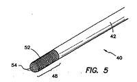
図4は、図3に例示された装置40に類似する多機能外科手術装置41の斜視図であるが、拡張遠位端49と、本発明の第2の実施形態による拡張遠位端または拡張先端部49と、それを覆うフィルター51とを備えている。本発明の別な実施形態では、図5は、図3に例示されているような外科手術装置40が、遠位端48に牽引力を高める構造54を取り付けたフィルター52を更に備えているのを例示している拡大図である。本発明のまた別な実施形態では、図6は、図4に例示されているような外科手術装置41が、遠位端または遠位先端部49に牽引力を高める構造55を設けたフィルター53を更に備えるのを例示した拡大図である。従来の吸引・潅注装置が血餅、脂肪、および/または、それ以外の生体破片で閉塞状態になってしまう傾向があるが、本件の牽引力を高める構造54、55のために使用される素材は、外科手術装置40、41の吸引構成部材の効果をそれぞれに高めている。濾過を供与するのに加えて、外科手術装置40、41の柔らかさを増した先端部は、出血する組織または血管を圧迫するのにも性能が勝っている。
4 is a perspective view of a multi-function
牽引力を高める構造54、55は、吸収特性を有する綿または綿に似た素材で形成される。これに代わる例として、牽引力を高める構造54、55は網状発泡材または連続気泡発泡材、もしくは、同様の海綿体(スポンジ)で形成することができる。牽引力を高めた構造54、55は各々が、成形され、ダイス状に切り分けられ、織物状にされ、編物状にされ、または、編組状にされた被覆(カバー)を含み、これが遠位端または遠位先端部48、49にそれぞれ着脱自在に装着されている。このような構成にした場合、牽引力を高める構造54、55は、既存の外科手術器具の鋸歯を模倣した摩擦構成部材を設けている。図8に例示されているように、編組管状スリーブ76が網状発泡材スリーブ77の上を覆って形成されている。編組管状スリーブ76は優れた牽引力を与えるが、発泡材スリーブ77は組織表面の凸凹または表面特性に非外傷性の可撓性と適合性を与える。編組管状スリーブ76は非弾性繊維で作られるのが好ましく、発泡材スリーブ77は柔らかく、多孔性で、弾性に富む素材で作られるのが好ましい。編組管状スリーブ76は、圧迫された場合でさえ、牽引力のある表面を維持するのが分かる。
上述のように、フィルター50、51、52、53の多孔性は、傷つきやすい組織または遊離組織が細長いシャフト42、43の開口部に入るのを阻止している。それにも関わらず、組織がフィルター50、51、52、53に押圧された場合、外科手術装置40、41の吸引機能は多孔性フィルターを通して自動的に再び分配されるため、装置40、41は、外科手術処置を中断しなくても、作業を継続することができる。その結果、外科手術装置40、41は、隠れた組織または構造体で真空閉鎖してしまうという事態の悪化を生じることなく、大量の血溜りの吸引を行うこととができる。フィルター50、51、52、53は多孔性素材から作られるのが好ましいが、このような素材により、細長いシャフト42、43の遠位端から外科手術部位まで潅注液を通すことができるようになる。
As mentioned above, the porosity of the
図7は、本発明のまた別な実施形態による多機能外科手術装置70を例示した側面断面図である。外科手術装置70は細長い管状シャフト72を備えており、その遠位端部74は直径が減じられている。直径を減じることで、器具シャフトの直径を実質的に増大させなくても、編組管状スリーブ76および発泡材スリーブ77を設けた、吸引力を高めたフィルターを設置することができる。例えば、5mm径の腹腔鏡吸引・潅注装置は5mm径の腹腔鏡套管針の中に適合するような寸法および形状に設定されているのが通例である。遠位装着部材がシャフトを覆って設置されると、吸引・潅注装置の増大した直径が套管針の出入りを妨げることがある。このように、細長いシャフト72の遠位端部74の直径を減じることで、牽引力を高めるフィルターを取り付けることができて、尚且つ、選択された套管針の中に適合させられる。図8は図7に例示されているような外科手術装置70の拡大図である。図9は、牽引力を高めたフィルターを装着する前の、外科手術装置70の遠位端の斜視図である。図10は、牽引力を高めたフィルターを装着した後の、外科手術装置70の遠位端の斜視図である。
FIG. 7 is a side cross-sectional view illustrating a multifunction
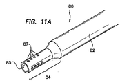
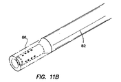
本発明の別な実施形態では、図11A、図11Bは、本発明の別な実施形態による、多機能外科手術装置80の斜視図を例示している。外科手術装置80は図7から図10に例示された装置70に類似しており、細長い管状シャフト82を備えており、その遠位端部84の直径が減じられている。遠位端84の先端85は実質的に開放状態であり、吸引穴87が設けられている。遠位端部84の直径を減じることで、シャフトの直径を実質的に増大させなくても、開放端を設けた、牽引力を高めたフィルター86を設置することができる。開放端を設けた、牽引力を高めたフィルター86の形状は、牽引力を高めたフィルター86が遠位端部84の上に装着された後で、開放遠位端85が開いたままになるように設定されている。本発明のまた別な実施形態では、図12A、図12Bは多機能外科手術装置90、95が細長いシャフト92、96をそれぞれに備えており、それぞれの遠位端部93、97の直径が減じられている斜視図を例示している。遠位端部93、97の直径を減じることで、そこに、より厚く、より吸収性に富み、より牽引力の高いフィルターを装着することができるようになる。更に、遠位端部93、97はそれぞれにより大型の吸引穴または吸引空間94、98が設けられており、これらが外科手術部位の吸引と潅注をより向上させる。
In another embodiment of the present invention, FIGS. 11A and 11B illustrate perspective views of a multi-function
本発明の精神および範囲から逸脱せずに、当業者なら多くの変更や修正を行うことができる。よって、例示の実施形態は具体例としてのみ明示されているにすぎないと解釈するべきであって、本発明の制限するものと理解するべきではない。 Many changes and modifications may be made by those skilled in the art without departing from the spirit and scope of the invention. Accordingly, the exemplary embodiments are to be construed as merely illustrative only and should not be construed as limiting the invention.
Claims (40)
細長いシャフトの遠位端に動作自在に装着されて組織を操作する移動先端部と、
細長いシャフトの近位端に動作自在に接続されて細長いシャフトを介して外科手術部位まで潅注液を選択的に搬入し、外科手術部位から潅注液を選択的に排除する弁組立体と、
を備えることを特徴とする外科手術装置。 An elongate shaft defining a lumen therein and having a proximal end and a distal end;
A moving tip that is operably attached to the distal end of the elongate shaft to manipulate tissue;
A valve assembly operatively connected to the proximal end of the elongate shaft to selectively carry irrigation fluid through the elongate shaft to the surgical site and selectively exclude irrigation fluid from the surgical site;
A surgical operation apparatus comprising:
細長いシャフトの遠位端に動作自在に装着された移動先端部と、
細長いシャフトの近位端に動作自在に接続されて細長いシャフトを介して外科手術部位まで潅注液を選択的に搬入し、外科手術部位から潅注液を選択的に排除する弁組立体とを備えており、
移動先端部は第1の直径と実質的に同じである外径を有しており、移動先端部を遠位端部に装着した後でも、細長いシャフトの直径が実質的に同じになるようにした、
ことを特徴とする外科手術装置。 An elongate shaft defining a lumen therein and provided with a proximal end having a first diameter and a distal end having a second diameter shorter than the first diameter;
A moving tip operably attached to the distal end of the elongated shaft;
A valve assembly operatively connected to the proximal end of the elongate shaft for selectively delivering irrigation fluid through the elongate shaft to the surgical site and selectively removing the irrigation fluid from the surgical site. And
The moving tip has an outer diameter that is substantially the same as the first diameter so that the diameter of the elongated shaft is substantially the same even after the moving tip is attached to the distal end. did,
A surgical apparatus characterized by that.
細長いシャフトの遠位端に動作自在に装着された移動先端部と、
細長いシャフトの近位端に動作自在に接続されて細長いシャフトを介して外科手術部位まで潅注液を選択的に搬入し、外科手術部位から潅注液を選択的に排除する弁組立体とを備えており、
外科手術装置は組織吸引、組織潅注、組織牽引、組織濾過、組織切除、組織圧迫などのうちの少なくとも1つを含む多機能性を提供する、
ことを特徴とする外科手術装置。 An elongate shaft defining a lumen therein and having a proximal end and a distal end;
A moving tip operably attached to the distal end of the elongated shaft;
A valve assembly operatively connected to the proximal end of the elongate shaft for selectively delivering irrigation fluid through the elongate shaft to the surgical site and selectively removing the irrigation fluid from the surgical site. And
The surgical device provides multi-functionality including at least one of tissue aspiration, tissue irrigation, tissue traction, tissue filtration, tissue resection, tissue compression, etc.
A surgical apparatus characterized by that.
Applications Claiming Priority (2)
| Application Number | Priority Date | Filing Date | Title |
|---|---|---|---|
| US10/768,608 US20050171467A1 (en) | 2004-01-30 | 2004-01-30 | Multiple function surgical device |
| PCT/US2005/004835 WO2005074815A2 (en) | 2004-01-30 | 2005-01-25 | Multiple function surgical device |
Publications (2)
| Publication Number | Publication Date |
|---|---|
| JP2007519501A true JP2007519501A (en) | 2007-07-19 |
| JP2007519501A5 JP2007519501A5 (en) | 2008-03-13 |
Family
ID=34807917
Family Applications (1)
| Application Number | Title | Priority Date | Filing Date |
|---|---|---|---|
| JP2006551647A Pending JP2007519501A (en) | 2004-01-30 | 2005-01-25 | Multi-function surgical device |
Country Status (6)
| Country | Link |
|---|---|
| US (1) | US20050171467A1 (en) |
| EP (1) | EP1708622A2 (en) |
| JP (1) | JP2007519501A (en) |
| AU (1) | AU2005209938A1 (en) |
| CA (1) | CA2552822A1 (en) |
| WO (1) | WO2005074815A2 (en) |
Cited By (5)
| Publication number | Priority date | Publication date | Assignee | Title |
|---|---|---|---|---|
| WO2014084266A1 (en) * | 2012-11-28 | 2014-06-05 | 日機装株式会社 | Fluid infusion instrument |
| WO2015170659A1 (en) * | 2014-05-08 | 2015-11-12 | 日機装株式会社 | Suction apparatus for body cavity fluid perfusion system |
| JP2016529976A (en) * | 2013-07-30 | 2016-09-29 | エスポジト,マイケル | Bending tip for laparoscopic surgery |
| JP2019146785A (en) * | 2018-02-27 | 2019-09-05 | 国立大学法人 東京大学 | Surgical instrument |
| JP2022512520A (en) * | 2018-11-21 | 2022-02-07 | バッファロー フィルター エルエルシー | Methods and equipment for flow |
Families Citing this family (37)
| Publication number | Priority date | Publication date | Assignee | Title |
|---|---|---|---|---|
| US7824384B2 (en) * | 2004-08-10 | 2010-11-02 | Kci Licensing, Inc. | Chest tube drainage system |
| US20070049860A1 (en) * | 2005-09-01 | 2007-03-01 | Robert Seminara | Apparatus and method for using a surgical instrument with an expandable sponge |
| US8235939B2 (en) | 2006-02-06 | 2012-08-07 | Kci Licensing, Inc. | System and method for purging a reduced pressure apparatus during the administration of reduced pressure treatment |
| BRPI0706893B8 (en) | 2006-02-06 | 2021-06-22 | Kci Licensing Inc | rotary reduced pressure adapter to connect a reduced pressure source to a porous pad. |
| US8915842B2 (en) * | 2008-07-14 | 2014-12-23 | Ethicon Endo-Surgery, Inc. | Methods and devices for maintaining visibility and providing irrigation and/or suction during surgical procedures |
| US8267908B2 (en) | 2007-02-09 | 2012-09-18 | Kci Licensing, Inc. | Delivery tube, system, and method for storing liquid from a tissue site |
| RU2459636C2 (en) | 2007-02-09 | 2012-08-27 | КейСиАй Лайсензинг Инк. | Apparatus and method for treating tissue region by applying low pressure |
| US8142356B2 (en) * | 2007-03-30 | 2012-03-27 | Ethicon Endo-Surgery, Inc. | Method of manipulating tissue |
| US8100930B2 (en) * | 2007-03-30 | 2012-01-24 | Ethicon Endo-Surgery, Inc. | Tissue moving surgical device |
| US9050036B2 (en) * | 2007-06-19 | 2015-06-09 | Minimally Invasive Devices, Inc. | Device for maintaining visualization with surgical scopes |
| US9211059B2 (en) | 2007-06-19 | 2015-12-15 | Minimally Invasive Devices, Inc. | Systems and methods for optimizing and maintaining visualization of a surgical field during the use of surgical scopes |
| US8157727B2 (en) * | 2007-07-16 | 2012-04-17 | Ethicon Endo-Surgery, Inc. | Surgical methods and devices with movement assistance |
| US20090234193A1 (en) * | 2008-03-13 | 2009-09-17 | Ethicon Endo-Surgery, Inc. | Apparatus for keeping clean a distal scope end of a medical viewing scope |
| US8540744B2 (en) * | 2008-04-01 | 2013-09-24 | Ethicon Endo-Surgery, Inc. | Tissue penetrating surgical device |
| DE102009005058A1 (en) * | 2008-06-16 | 2010-07-22 | T.A. Dental Innovations S.A.R.L. | Forceps-type device for extracting fluid i.e. patient's blood, exiting from wound area for preparation of e.g. synthetic bone grafting material, has pores for absorbing fluid contacted by contact device into interior of contact device |
| USD613403S1 (en) | 2008-12-10 | 2010-04-06 | Minimally Invasive Devices, Llc | Sheath tip for maintaining surgical scope visualization |
| EP2361034B1 (en) | 2008-12-10 | 2014-07-30 | Minimally Invasive Devices, Inc. | Systems and methods for optimizing and maintaining visualization of a surgical field during the use of surgical scopes |
| RU2011127674A (en) | 2008-12-31 | 2013-02-10 | КейСиАй ЛАЙСЕНЗИНГ, ИНК. | HIGHWAYS, SYSTEMS AND METHODS FOR APPLYING THE REDUCED PRESSURE TO THE SUBSTANCE OF THE SUBCUTANEOUS TISSUE |
| RU2011122547A (en) * | 2008-12-31 | 2013-02-10 | КейСиАй ЛАЙСЕНЗИНГ, ИНК. | FABRIC Framed Rolls |
| US8529526B2 (en) | 2009-10-20 | 2013-09-10 | Kci Licensing, Inc. | Dressing reduced-pressure indicators, systems, and methods |
| US9078562B2 (en) | 2010-01-11 | 2015-07-14 | Minimally Invasive Devices, Inc. | Systems and methods for optimizing and maintaining visualization of a surgical field during the use of surgical scopes |
| WO2012075487A2 (en) | 2010-12-03 | 2012-06-07 | Minimally Invasive Devices, Llc | Devices, systems, and methods for performing endoscopic surgical procedures |
| CN102100576A (en) * | 2011-03-08 | 2011-06-22 | 中国人民解放军第三军医大学第二附属医院 | Marrow puncture and collection needle |
| WO2012158516A2 (en) * | 2011-05-13 | 2012-11-22 | Vascular Technology Inc. | Remotely controlled suction/irrigation for surgery |
| US8728090B2 (en) * | 2012-01-12 | 2014-05-20 | Mohamad Farhadi | Tonsillar suction dissector |
| WO2013133778A1 (en) * | 2012-03-08 | 2013-09-12 | Ozer Tahir M | Sponge sheath for laparoscopic aspirator |
| EP2897662B1 (en) * | 2012-09-20 | 2020-05-06 | Lohmann & Rauscher GmbH | Vacuum treatment array and film for producing a vacuum treatment array |
| WO2014097243A1 (en) * | 2012-12-21 | 2014-06-26 | Koninklijke Philips N.V. | Plaque detection using a stream probe |
| WO2014151824A1 (en) | 2013-03-14 | 2014-09-25 | Minimally Invasive Devices, Inc. | Fluid dispensing control systems and methods |
| CN105579079A (en) * | 2013-07-25 | 2016-05-11 | 柯惠有限合伙公司 | Multifunctional telescoping cleaning device |
| US20150297344A1 (en) * | 2014-04-21 | 2015-10-22 | Arvind Saini | Irrigating intraocular lens rotators and related methods |
| US20160346511A1 (en) * | 2015-06-01 | 2016-12-01 | Webb Medical LLC | Middle ear surgical attachments for suction catheters and suction catheters including the same |
| EP3325079B1 (en) | 2015-07-23 | 2023-09-06 | Novaflux, Inc. | Implants and constructs including hollow fibers |
| GB201519652D0 (en) * | 2015-11-06 | 2015-12-23 | Dentmed Ltd | Surgical tool |
| US20190336677A1 (en) * | 2016-06-24 | 2019-11-07 | Multigate Medical Products Pty Ltd | Suction and irrigation apparatus |
| US11026715B2 (en) | 2017-09-28 | 2021-06-08 | John Mayberry | Chest cavity suction medical apparatus and method |
| US10512473B2 (en) | 2017-10-31 | 2019-12-24 | Dentmed Limited | Surgical tool |
Citations (3)
| Publication number | Priority date | Publication date | Assignee | Title |
|---|---|---|---|---|
| JPH1094544A (en) * | 1996-08-02 | 1998-04-14 | Olympus Optical Co Ltd | Surgical device for peeling |
| JPH10179594A (en) * | 1996-12-25 | 1998-07-07 | Asahi Optical Co Ltd | Exfoliation tool for operation under observation with endoscope |
| JP2000237201A (en) * | 1999-02-18 | 2000-09-05 | Sumitomo Bakelite Co Ltd | Sucking-separating cap for operation under endoscope, and clamp |
Family Cites Families (103)
| Publication number | Priority date | Publication date | Assignee | Title |
|---|---|---|---|---|
| US1698331A (en) * | 1925-07-15 | 1929-01-08 | Newton C Gunter | Saliva ejector |
| US2470665A (en) * | 1947-07-08 | 1949-05-17 | Stiehl Charles William | Suction apparatus |
| US2510198A (en) * | 1947-10-17 | 1950-06-06 | Earl B Tesmer | Flexible positioner |
| US2595666A (en) * | 1949-05-03 | 1952-05-06 | Clifford L Hutson | Saliva ejector |
| GB983560A (en) * | 1962-09-18 | 1965-02-17 | Polymathic Engineering Company | Supporting stand for instruments, tools and the like |
| US3430662A (en) * | 1964-09-21 | 1969-03-04 | Stephen Guarnaschelli | Flexible segmented tube |
| US3324855A (en) * | 1965-01-12 | 1967-06-13 | Henry J Heimlich | Surgical sponge stick |
| JPS4831554B1 (en) * | 1968-12-24 | 1973-09-29 | ||
| US3669116A (en) * | 1970-07-06 | 1972-06-13 | Heyer Schulte Corp | Drainage catheter with anticlogging means |
| US3739770A (en) * | 1970-10-09 | 1973-06-19 | Olympus Optical Co | Bendable tube of an endoscope |
| US3946727A (en) * | 1971-06-15 | 1976-03-30 | Olympus Optical Co., Ltd. | Flexible tube assembly for an endoscope |
| US3807401A (en) * | 1972-06-21 | 1974-04-30 | Department Of Health Education | Anticoagulating blood suction device |
| US3858578A (en) * | 1974-01-21 | 1975-01-07 | Pravel Wilson & Matthews | Surgical retaining device |
| US3935863A (en) * | 1974-07-19 | 1976-02-03 | Kliger Herbert L | Surgical sponge |
| USD243283S (en) * | 1975-02-06 | 1977-02-01 | Dart Industries Inc. | Medical suction instrument tip |
| US4068664A (en) * | 1976-02-25 | 1978-01-17 | Texas Medical Products, Inc. | Surgical suction wand assembly and method |
| US4068644A (en) * | 1976-06-25 | 1978-01-17 | Colt Industries Operating Corporation | Rewind starter pulley assembly |
| US4158916A (en) * | 1977-07-20 | 1979-06-26 | Adler Harold A | Suction apparatus |
| JPS5586435A (en) * | 1978-12-22 | 1980-06-30 | Olympus Optical Co | Endoscope |
| JPS6041203Y2 (en) * | 1979-04-03 | 1985-12-14 | 富士写真光機株式会社 | Curved tube part of endoscope |
| US4265621A (en) * | 1979-10-19 | 1981-05-05 | Mcvey Kenneth E | Tip for dental aspirator |
| JPS606652B2 (en) * | 1979-11-16 | 1985-02-19 | オリンパス光学工業株式会社 | Flexible tube for endoscope |
| US4366810A (en) * | 1980-08-28 | 1983-01-04 | Slanetz Jr Charles A | Tactile control device for a remote sensing device |
| EP0077526B1 (en) * | 1981-10-15 | 1987-09-16 | Olympus Optical Co., Ltd. | Endoscope system with an electric bending mechanism |
| JPS5878639A (en) * | 1981-11-04 | 1983-05-12 | オリンパス光学工業株式会社 | Endoscope |
| JPS60187737U (en) * | 1984-05-23 | 1985-12-12 | オリンパス光学工業株式会社 | Indwelling tube guide device |
| US4651718A (en) * | 1984-06-29 | 1987-03-24 | Warner-Lambert Technologies Inc. | Vertebra for articulatable shaft |
| DE3426024A1 (en) * | 1984-07-14 | 1986-01-16 | Robert 5442 Mendig Merkt | KIT FOR MANUFACTURING AN ASSEMBLY GAUGE FOR PIPELINES, IN PARTICULAR PIPELINES FOR HYDRAULIC OR PNEUMATIC SWITCHING OR. WORKING PARTIES |
| US4577621A (en) * | 1984-12-03 | 1986-03-25 | Patel Jayendrakumar I | Endoscope having novel proximate and distal portions |
| US4646722A (en) * | 1984-12-10 | 1987-03-03 | Opielab, Inc. | Protective endoscope sheath and method of installing same |
| JPH055529Y2 (en) * | 1985-03-25 | 1993-02-15 | ||
| US4799474A (en) * | 1986-03-13 | 1989-01-24 | Olympus Optical Co., Ltd. | Medical tube to be inserted in body cavity |
| DE3734979A1 (en) * | 1986-10-16 | 1988-04-28 | Olympus Optical Co | ENDOSCOPE |
| US4753223A (en) * | 1986-11-07 | 1988-06-28 | Bremer Paul W | System for controlling shape and direction of a catheter, cannula, electrode, endoscope or similar article |
| US4895431A (en) * | 1986-11-13 | 1990-01-23 | Olympus Optical Co., Ltd. | Method of processing endoscopic images |
| US4832473A (en) * | 1987-02-06 | 1989-05-23 | Olympus Optical Co., Ltd. | Endoscope with elastic actuator comprising a synthetic rubber tube with only radial expansion controlled by a mesh-like tube |
| EP0549569B1 (en) * | 1987-02-09 | 1995-01-25 | Sumitomo Electric Industries Limited | Mechanism for bending elongated body |
| US4796607A (en) * | 1987-07-28 | 1989-01-10 | Welch Allyn, Inc. | Endoscope steering section |
| US4935006A (en) * | 1987-11-12 | 1990-06-19 | Hasson Harrith M | Suction and irrigation device with right angle and oblique openings |
| US4890602A (en) * | 1987-11-25 | 1990-01-02 | Hake Lawrence W | Endoscope construction with means for controlling rigidity and curvature of flexible endoscope tube |
| US4815450A (en) * | 1988-02-01 | 1989-03-28 | Patel Jayendra I | Endoscope having variable flexibility |
| US4930494A (en) * | 1988-03-09 | 1990-06-05 | Olympus Optical Co., Ltd. | Apparatus for bending an insertion section of an endoscope using a shape memory alloy |
| US4834068A (en) * | 1988-03-18 | 1989-05-30 | Gottesman James E | Barrier shield method and apparatus for optical-medical devices |
| US4987314A (en) * | 1988-04-21 | 1991-01-22 | Olympus Optical Co., Ltd. | Actuator apparatus utilizing a shape-memory alloy |
| US5451204A (en) * | 1988-07-22 | 1995-09-19 | Yoon; Inbae | Multifunctional devices for endoscopic surgical procedures |
| US5556376A (en) * | 1988-07-22 | 1996-09-17 | Yoon; Inbae | Multifunctional devices having loop configured portions and collection systems for endoscopic surgical procedures and methods thereof |
| US5018509A (en) * | 1989-02-21 | 1991-05-28 | Olympus Optical Co., Ltd. | Endoscope insertion controlling apparatus |
| US5203769A (en) * | 1989-11-06 | 1993-04-20 | Mectra Labs, Inc. | Medical device valving mechanism |
| US5092901A (en) * | 1990-06-06 | 1992-03-03 | The Royal Institution For The Advancement Of Learning (Mcgill University) | Shape memory alloy fibers having rapid twitch response |
| US5843017A (en) * | 1990-07-24 | 1998-12-01 | Yoon; Inbae | Multifunctional tissue dissecting instrument |
| US5085633A (en) * | 1990-08-22 | 1992-02-04 | Sage Products, Inc. | Method of forming suction swab |
| US5125395A (en) * | 1990-09-12 | 1992-06-30 | Adair Edwin Lloyd | Deflectable sheath for optical catheter |
| US5094616A (en) * | 1990-12-21 | 1992-03-10 | Myron Levenson | Dental appliance |
| US5188111A (en) * | 1991-01-18 | 1993-02-23 | Catheter Research, Inc. | Device for seeking an area of interest within a body |
| US5400769A (en) * | 1991-02-18 | 1995-03-28 | Olympus Optical Co., Ltd. | Electrically bendable endoscope apparatus having controlled fixed bending speed |
| JPH05184526A (en) * | 1991-09-17 | 1993-07-27 | Olympus Optical Co Ltd | Bending mechanism for flexible tube |
| JP3149219B2 (en) * | 1991-10-15 | 2001-03-26 | 旭光学工業株式会社 | Covering structure of curved part of endoscope |
| US5624380A (en) * | 1992-03-12 | 1997-04-29 | Olympus Optical Co., Ltd. | Multi-degree of freedom manipulator |
| US5482029A (en) * | 1992-06-26 | 1996-01-09 | Kabushiki Kaisha Toshiba | Variable flexibility endoscope system |
| US5402768A (en) * | 1992-09-01 | 1995-04-04 | Adair; Edwin L. | Endoscope with reusable core and disposable sheath with passageways |
| US5383852A (en) * | 1992-12-04 | 1995-01-24 | C. R. Bard, Inc. | Catheter with independent proximal and distal control |
| US5507717A (en) * | 1993-05-24 | 1996-04-16 | Olympus Optical Co., Ltd. | Device for bending the insertion section of an endoscope |
| US5487757A (en) * | 1993-07-20 | 1996-01-30 | Medtronic Cardiorhythm | Multicurve deflectable catheter |
| DE59409196D1 (en) * | 1993-08-30 | 2000-04-13 | Stm Medtech Starnberg | Piezoelectric linear drive element |
| US5389222A (en) * | 1993-09-21 | 1995-02-14 | The United States Of America As Represented By The United States Department Of Energy | Spring-loaded polymeric gel actuators |
| US5577992A (en) * | 1993-10-05 | 1996-11-26 | Asahi Kogaku Kogyo Kabushiki Kaisha | Bendable portion of endoscope |
| US5599330A (en) * | 1993-11-23 | 1997-02-04 | Rainin; Edgar A. | Surgical wicking device |
| US5449206A (en) * | 1994-01-04 | 1995-09-12 | Lockwood Products, Inc. | Ball and socket joint with internal stop |
| US5624381A (en) * | 1994-08-09 | 1997-04-29 | Kieturakis; Maciej J. | Surgical instrument and method for retraction of an anatomic structure defining an interior lumen |
| US5728044A (en) * | 1995-03-10 | 1998-03-17 | Shan; Yansong | Sensor device for spacial imaging of endoscopes |
| US5620408A (en) * | 1995-04-14 | 1997-04-15 | Vennes; Jack A. | Endoscopic over-tube |
| US5667476A (en) * | 1995-06-05 | 1997-09-16 | Vision-Sciences, Inc. | Endoscope articulation system to reduce effort during articulation of an endoscope |
| US6210337B1 (en) * | 1995-06-07 | 2001-04-03 | Atl Ultrasound Inc. | Ultrasonic endoscopic probe |
| US5752912A (en) * | 1995-06-26 | 1998-05-19 | Asahi Kogaku Kogyo Kabushiki Kaisha | Manipulator for flexible portion of an endoscope |
| IL124822A (en) * | 1995-12-11 | 2000-12-06 | Primordial L L C | Construction system |
| JP3221824B2 (en) * | 1995-12-19 | 2001-10-22 | 富士写真光機株式会社 | Endoscope with bending section protection mechanism |
| US5749828A (en) * | 1995-12-22 | 1998-05-12 | Hewlett-Packard Company | Bending neck for use with invasive medical devices |
| US5628735A (en) * | 1996-01-11 | 1997-05-13 | Skow; Joseph I. | Surgical device for wicking and removing fluid |
| DE69735146T2 (en) * | 1996-05-09 | 2006-09-28 | Olympus Corporation | Surgical tool for holding a cavity |
| US5902254A (en) * | 1996-07-29 | 1999-05-11 | The Nemours Foundation | Cathether guidewire |
| US5685822A (en) * | 1996-08-08 | 1997-11-11 | Vision-Sciences, Inc. | Endoscope with sheath retaining device |
| IT1285533B1 (en) * | 1996-10-22 | 1998-06-08 | Scuola Superiore Di Studi Universitari E Di Perfezionamento Sant Anna | ENDOSCOPIC ROBOT |
| DE19748795B4 (en) * | 1996-11-18 | 2006-08-17 | Olympus Corporation | endoscope |
| US5885208A (en) * | 1996-12-24 | 1999-03-23 | Olympus Optical Co., Ltd. | Endoscope system |
| US5876373A (en) * | 1997-04-04 | 1999-03-02 | Eclipse Surgical Technologies, Inc. | Steerable catheter |
| US6371934B1 (en) * | 1997-08-06 | 2002-04-16 | C. R. Bard, Inc. | Irrigation system and tip with debrider |
| JP2002502626A (en) * | 1998-02-10 | 2002-01-29 | アーテミス・メディカル・インコーポレイテッド | Supplementary device and method of using the same |
| DE19815598B4 (en) * | 1998-04-07 | 2007-01-18 | Stm Medizintechnik Starnberg Gmbh | Flexible access tube with everting tube system |
| US6066132A (en) * | 1998-06-30 | 2000-05-23 | Ethicon, Inc. | Articulating endometrial ablation device |
| DE19840986A1 (en) * | 1998-09-08 | 2000-03-09 | Etm Endoskopische Technik Gmbh | Quick release for an endoscope |
| US6174280B1 (en) * | 1998-11-19 | 2001-01-16 | Vision Sciences, Inc. | Sheath for protecting and altering the bending characteristics of a flexible endoscope |
| US20020000040A1 (en) * | 1998-12-21 | 2002-01-03 | The Gillette Company | Safety razors |
| US6179776B1 (en) * | 1999-03-12 | 2001-01-30 | Scimed Life Systems, Inc. | Controllable endoscopic sheath apparatus and related method of use |
| US6068477A (en) * | 1999-07-06 | 2000-05-30 | Mahlmann; Lee A. | Foam-cushioned aspirator |
| US6391040B1 (en) * | 1999-11-15 | 2002-05-21 | George C. Christoudias | Christoudias endodissector |
| JP3765218B2 (en) * | 2000-02-03 | 2006-04-12 | フジノン株式会社 | Endoscope operation wire guide device |
| CA2536163A1 (en) * | 2000-04-03 | 2005-03-03 | Neoguide Systems, Inc. | Activated polymer articulated instruments and methods of insertion |
| US6468203B2 (en) * | 2000-04-03 | 2002-10-22 | Neoguide Systems, Inc. | Steerable endoscope and improved method of insertion |
| US6610007B2 (en) * | 2000-04-03 | 2003-08-26 | Neoguide Systems, Inc. | Steerable segmented endoscope and method of insertion |
| US6858005B2 (en) * | 2000-04-03 | 2005-02-22 | Neo Guide Systems, Inc. | Tendon-driven endoscope and methods of insertion |
| JP2003135381A (en) * | 2001-10-31 | 2003-05-13 | Machida Endscope Co Ltd | Curved tube and its manufacturing method |
| NL1020597C2 (en) * | 2002-05-14 | 2003-11-17 | Surge On Medical Innovations B | Suction tip is for suction tube used in micro-surgical procedures for removal of cerebro-spinal fluid and/or irrigated medium, and/or blood from surgical site and comprises spongy, porous material with open pores |
| US7250027B2 (en) * | 2002-05-30 | 2007-07-31 | Karl Storz Endovision, Inc. | Articulating vertebrae with asymmetrical and variable radius of curvature |
-
2004
- 2004-01-30 US US10/768,608 patent/US20050171467A1/en not_active Abandoned
-
2005
- 2005-01-25 JP JP2006551647A patent/JP2007519501A/en active Pending
- 2005-01-25 AU AU2005209938A patent/AU2005209938A1/en not_active Abandoned
- 2005-01-25 CA CA002552822A patent/CA2552822A1/en not_active Abandoned
- 2005-01-25 EP EP05713623A patent/EP1708622A2/en not_active Withdrawn
- 2005-01-25 WO PCT/US2005/004835 patent/WO2005074815A2/en not_active Application Discontinuation
Patent Citations (3)
| Publication number | Priority date | Publication date | Assignee | Title |
|---|---|---|---|---|
| JPH1094544A (en) * | 1996-08-02 | 1998-04-14 | Olympus Optical Co Ltd | Surgical device for peeling |
| JPH10179594A (en) * | 1996-12-25 | 1998-07-07 | Asahi Optical Co Ltd | Exfoliation tool for operation under observation with endoscope |
| JP2000237201A (en) * | 1999-02-18 | 2000-09-05 | Sumitomo Bakelite Co Ltd | Sucking-separating cap for operation under endoscope, and clamp |
Cited By (8)
| Publication number | Priority date | Publication date | Assignee | Title |
|---|---|---|---|---|
| WO2014084266A1 (en) * | 2012-11-28 | 2014-06-05 | 日機装株式会社 | Fluid infusion instrument |
| JP2014128581A (en) * | 2012-11-28 | 2014-07-10 | Nikkiso Co Ltd | Liquid injection instrument |
| JP2016529976A (en) * | 2013-07-30 | 2016-09-29 | エスポジト,マイケル | Bending tip for laparoscopic surgery |
| WO2015170659A1 (en) * | 2014-05-08 | 2015-11-12 | 日機装株式会社 | Suction apparatus for body cavity fluid perfusion system |
| JPWO2015170659A1 (en) * | 2014-05-08 | 2017-04-20 | 日機装株式会社 | Inhalation device for intraperitoneal fluid perfusion system |
| US10413645B2 (en) | 2014-05-08 | 2019-09-17 | Nikkiso Co., Ltd. | Suction apparatus for peritoneal cavity fluid perfusion system |
| JP2019146785A (en) * | 2018-02-27 | 2019-09-05 | 国立大学法人 東京大学 | Surgical instrument |
| JP2022512520A (en) * | 2018-11-21 | 2022-02-07 | バッファロー フィルター エルエルシー | Methods and equipment for flow |
Also Published As
| Publication number | Publication date |
|---|---|
| AU2005209938A1 (en) | 2005-08-18 |
| US20050171467A1 (en) | 2005-08-04 |
| EP1708622A2 (en) | 2006-10-11 |
| WO2005074815A3 (en) | 2006-10-12 |
| WO2005074815A2 (en) | 2005-08-18 |
| CA2552822A1 (en) | 2005-08-18 |
Similar Documents
| Publication | Publication Date | Title |
|---|---|---|
| JP2007519501A (en) | Multi-function surgical device | |
| CA2296305C (en) | Pneumatic tissue dissector with exhaust system | |
| EP1891998B1 (en) | Surgical aspiration system | |
| JP3261143B2 (en) | Laparoscopy and electrosurgical instruments | |
| AU773181B2 (en) | Fluid jet surgical instruments | |
| CA2474311C (en) | Pistol grip electrosurgical pencil with manual aspirator/irrigator and methods of using the same | |
| US20070213667A1 (en) | Suction Irrigation Cleaner | |
| US20160206369A1 (en) | Laparoscopic suction device and method | |
| WO2003006084A2 (en) | Enlargeable multifunctional devices | |
| WO2000029045A1 (en) | Vented aspirator and method | |
| CA2649518A1 (en) | Suction dome for atraumatically grasping or manipulating tissue | |
| JP5990320B2 (en) | Surgical instruments | |
| JP6348497B2 (en) | Variable suction controller | |
| JP2007527745A (en) | Instruments and methods for removing obstructions from surgical cutting instruments | |
| US5310406A (en) | Endoscopic aspirator surgical instrument | |
| WO2006093900A2 (en) | Multi-functional medical instrument and methods of use | |
| EP0578376A1 (en) | Ultrasonic surgical aspirator | |
| JP2001231850A (en) | Medical suction tube utilizing capillary phenomenon | |
| JP2599947Y2 (en) | Medical peeling suction beak tube | |
| US20240181179A1 (en) | System and method for visualization of a surgical site during a medical procedure | |
| CN219629730U (en) | Forceps head rotatable integrated sucking forceps for laparoscope | |
| KR102371974B1 (en) | Suction aspirator | |
| JP3265452B2 (en) | Medical peeling suction beak tube | |
| CN211100697U (en) | Smoke discharging device for laparoscopic surgery | |
| US20220296803A1 (en) | Surgical device comprising a rod having a deformable sleeve at its distal end surrounding said rod |
Legal Events
| Date | Code | Title | Description |
|---|---|---|---|
| A521 | Request for written amendment filed |
Free format text: JAPANESE INTERMEDIATE CODE: A523 Effective date: 20080125 |
|
| A621 | Written request for application examination |
Free format text: JAPANESE INTERMEDIATE CODE: A621 Effective date: 20080125 |
|
| A977 | Report on retrieval |
Free format text: JAPANESE INTERMEDIATE CODE: A971007 Effective date: 20100730 |
|
| A131 | Notification of reasons for refusal |
Free format text: JAPANESE INTERMEDIATE CODE: A131 Effective date: 20100806 |
|
| A601 | Written request for extension of time |
Free format text: JAPANESE INTERMEDIATE CODE: A601 Effective date: 20101108 |
|
| A602 | Written permission of extension of time |
Free format text: JAPANESE INTERMEDIATE CODE: A602 Effective date: 20101115 |
|
| A02 | Decision of refusal |
Free format text: JAPANESE INTERMEDIATE CODE: A02 Effective date: 20110404 |