RU2459636C2 - Apparatus and method for treating tissue region by applying low pressure - Google Patents
Apparatus and method for treating tissue region by applying low pressure Download PDFInfo
- Publication number
- RU2459636C2 RU2459636C2 RU2009123208/14A RU2009123208A RU2459636C2 RU 2459636 C2 RU2459636 C2 RU 2459636C2 RU 2009123208/14 A RU2009123208/14 A RU 2009123208/14A RU 2009123208 A RU2009123208 A RU 2009123208A RU 2459636 C2 RU2459636 C2 RU 2459636C2
- Authority
- RU
- Russia
- Prior art keywords
- reduced pressure
- indicator
- tube
- tissue site
- channel
- Prior art date
Links
Images


Classifications
-
- A—HUMAN NECESSITIES
- A61—MEDICAL OR VETERINARY SCIENCE; HYGIENE
- A61M—DEVICES FOR INTRODUCING MEDIA INTO, OR ONTO, THE BODY; DEVICES FOR TRANSDUCING BODY MEDIA OR FOR TAKING MEDIA FROM THE BODY; DEVICES FOR PRODUCING OR ENDING SLEEP OR STUPOR
- A61M27/00—Drainage appliance for wounds or the like, i.e. wound drains, implanted drains
-
- A—HUMAN NECESSITIES
- A61—MEDICAL OR VETERINARY SCIENCE; HYGIENE
- A61M—DEVICES FOR INTRODUCING MEDIA INTO, OR ONTO, THE BODY; DEVICES FOR TRANSDUCING BODY MEDIA OR FOR TAKING MEDIA FROM THE BODY; DEVICES FOR PRODUCING OR ENDING SLEEP OR STUPOR
- A61M1/00—Suction or pumping devices for medical purposes; Devices for carrying-off, for treatment of, or for carrying-over, body-liquids; Drainage systems
- A61M1/60—Containers for suction drainage, adapted to be used with an external suction source
-
- A—HUMAN NECESSITIES
- A61—MEDICAL OR VETERINARY SCIENCE; HYGIENE
- A61M—DEVICES FOR INTRODUCING MEDIA INTO, OR ONTO, THE BODY; DEVICES FOR TRANSDUCING BODY MEDIA OR FOR TAKING MEDIA FROM THE BODY; DEVICES FOR PRODUCING OR ENDING SLEEP OR STUPOR
- A61M1/00—Suction or pumping devices for medical purposes; Devices for carrying-off, for treatment of, or for carrying-over, body-liquids; Drainage systems
- A61M1/71—Suction drainage systems
- A61M1/73—Suction drainage systems comprising sensors or indicators for physical values
- A61M1/732—Visual indicating means for vacuum pressure
-
- A—HUMAN NECESSITIES
- A61—MEDICAL OR VETERINARY SCIENCE; HYGIENE
- A61M—DEVICES FOR INTRODUCING MEDIA INTO, OR ONTO, THE BODY; DEVICES FOR TRANSDUCING BODY MEDIA OR FOR TAKING MEDIA FROM THE BODY; DEVICES FOR PRODUCING OR ENDING SLEEP OR STUPOR
- A61M1/00—Suction or pumping devices for medical purposes; Devices for carrying-off, for treatment of, or for carrying-over, body-liquids; Drainage systems
- A61M1/90—Negative pressure wound therapy devices, i.e. devices for applying suction to a wound to promote healing, e.g. including a vacuum dressing
- A61M1/91—Suction aspects of the dressing
- A61M1/915—Constructional details of the pressure distribution manifold
-
- A—HUMAN NECESSITIES
- A61—MEDICAL OR VETERINARY SCIENCE; HYGIENE
- A61M—DEVICES FOR INTRODUCING MEDIA INTO, OR ONTO, THE BODY; DEVICES FOR TRANSDUCING BODY MEDIA OR FOR TAKING MEDIA FROM THE BODY; DEVICES FOR PRODUCING OR ENDING SLEEP OR STUPOR
- A61M1/00—Suction or pumping devices for medical purposes; Devices for carrying-off, for treatment of, or for carrying-over, body-liquids; Drainage systems
- A61M1/90—Negative pressure wound therapy devices, i.e. devices for applying suction to a wound to promote healing, e.g. including a vacuum dressing
- A61M1/91—Suction aspects of the dressing
- A61M1/916—Suction aspects of the dressing specially adapted for deep wounds
-
- A—HUMAN NECESSITIES
- A61—MEDICAL OR VETERINARY SCIENCE; HYGIENE
- A61M—DEVICES FOR INTRODUCING MEDIA INTO, OR ONTO, THE BODY; DEVICES FOR TRANSDUCING BODY MEDIA OR FOR TAKING MEDIA FROM THE BODY; DEVICES FOR PRODUCING OR ENDING SLEEP OR STUPOR
- A61M1/00—Suction or pumping devices for medical purposes; Devices for carrying-off, for treatment of, or for carrying-over, body-liquids; Drainage systems
- A61M1/90—Negative pressure wound therapy devices, i.e. devices for applying suction to a wound to promote healing, e.g. including a vacuum dressing
- A61M1/98—Containers specifically adapted for negative pressure wound therapy
- A61M1/982—Containers specifically adapted for negative pressure wound therapy with means for detecting level of collected exudate
-
- A—HUMAN NECESSITIES
- A61—MEDICAL OR VETERINARY SCIENCE; HYGIENE
- A61M—DEVICES FOR INTRODUCING MEDIA INTO, OR ONTO, THE BODY; DEVICES FOR TRANSDUCING BODY MEDIA OR FOR TAKING MEDIA FROM THE BODY; DEVICES FOR PRODUCING OR ENDING SLEEP OR STUPOR
- A61M37/00—Other apparatus for introducing media into the body; Percutany, i.e. introducing medicines into the body by diffusion through the skin
-
- A—HUMAN NECESSITIES
- A61—MEDICAL OR VETERINARY SCIENCE; HYGIENE
- A61M—DEVICES FOR INTRODUCING MEDIA INTO, OR ONTO, THE BODY; DEVICES FOR TRANSDUCING BODY MEDIA OR FOR TAKING MEDIA FROM THE BODY; DEVICES FOR PRODUCING OR ENDING SLEEP OR STUPOR
- A61M1/00—Suction or pumping devices for medical purposes; Devices for carrying-off, for treatment of, or for carrying-over, body-liquids; Drainage systems
- A61M1/71—Suction drainage systems
- A61M1/78—Means for preventing overflow or contamination of the pumping systems
-
- A—HUMAN NECESSITIES
- A61—MEDICAL OR VETERINARY SCIENCE; HYGIENE
- A61M—DEVICES FOR INTRODUCING MEDIA INTO, OR ONTO, THE BODY; DEVICES FOR TRANSDUCING BODY MEDIA OR FOR TAKING MEDIA FROM THE BODY; DEVICES FOR PRODUCING OR ENDING SLEEP OR STUPOR
- A61M1/00—Suction or pumping devices for medical purposes; Devices for carrying-off, for treatment of, or for carrying-over, body-liquids; Drainage systems
- A61M1/88—Draining devices having means for processing the drained fluid, e.g. an absorber
- A61M1/882—Draining devices provided with means for releasing antimicrobial or gelation agents in the drained fluid
-
- A—HUMAN NECESSITIES
- A61—MEDICAL OR VETERINARY SCIENCE; HYGIENE
- A61M—DEVICES FOR INTRODUCING MEDIA INTO, OR ONTO, THE BODY; DEVICES FOR TRANSDUCING BODY MEDIA OR FOR TAKING MEDIA FROM THE BODY; DEVICES FOR PRODUCING OR ENDING SLEEP OR STUPOR
- A61M1/00—Suction or pumping devices for medical purposes; Devices for carrying-off, for treatment of, or for carrying-over, body-liquids; Drainage systems
- A61M1/90—Negative pressure wound therapy devices, i.e. devices for applying suction to a wound to promote healing, e.g. including a vacuum dressing
- A61M1/92—Negative pressure wound therapy devices, i.e. devices for applying suction to a wound to promote healing, e.g. including a vacuum dressing with liquid supply means
-
- A—HUMAN NECESSITIES
- A61—MEDICAL OR VETERINARY SCIENCE; HYGIENE
- A61M—DEVICES FOR INTRODUCING MEDIA INTO, OR ONTO, THE BODY; DEVICES FOR TRANSDUCING BODY MEDIA OR FOR TAKING MEDIA FROM THE BODY; DEVICES FOR PRODUCING OR ENDING SLEEP OR STUPOR
- A61M25/00—Catheters; Hollow probes
- A61M25/0021—Catheters; Hollow probes characterised by the form of the tubing
- A61M25/0023—Catheters; Hollow probes characterised by the form of the tubing by the form of the lumen, e.g. cross-section, variable diameter
- A61M25/0026—Multi-lumen catheters with stationary elements
- A61M2025/0036—Multi-lumen catheters with stationary elements with more than four lumina
-
- A—HUMAN NECESSITIES
- A61—MEDICAL OR VETERINARY SCIENCE; HYGIENE
- A61M—DEVICES FOR INTRODUCING MEDIA INTO, OR ONTO, THE BODY; DEVICES FOR TRANSDUCING BODY MEDIA OR FOR TAKING MEDIA FROM THE BODY; DEVICES FOR PRODUCING OR ENDING SLEEP OR STUPOR
- A61M25/00—Catheters; Hollow probes
- A61M25/0021—Catheters; Hollow probes characterised by the form of the tubing
- A61M25/0023—Catheters; Hollow probes characterised by the form of the tubing by the form of the lumen, e.g. cross-section, variable diameter
- A61M25/0026—Multi-lumen catheters with stationary elements
- A61M2025/004—Multi-lumen catheters with stationary elements characterized by lumina being arranged circumferentially
-
- A—HUMAN NECESSITIES
- A61—MEDICAL OR VETERINARY SCIENCE; HYGIENE
- A61M—DEVICES FOR INTRODUCING MEDIA INTO, OR ONTO, THE BODY; DEVICES FOR TRANSDUCING BODY MEDIA OR FOR TAKING MEDIA FROM THE BODY; DEVICES FOR PRODUCING OR ENDING SLEEP OR STUPOR
- A61M2205/00—General characteristics of the apparatus
- A61M2205/15—Detection of leaks
-
- A—HUMAN NECESSITIES
- A61—MEDICAL OR VETERINARY SCIENCE; HYGIENE
- A61M—DEVICES FOR INTRODUCING MEDIA INTO, OR ONTO, THE BODY; DEVICES FOR TRANSDUCING BODY MEDIA OR FOR TAKING MEDIA FROM THE BODY; DEVICES FOR PRODUCING OR ENDING SLEEP OR STUPOR
- A61M2205/00—General characteristics of the apparatus
- A61M2205/33—Controlling, regulating or measuring
- A61M2205/3331—Pressure; Flow
- A61M2205/3334—Measuring or controlling the flow rate
-
- A—HUMAN NECESSITIES
- A61—MEDICAL OR VETERINARY SCIENCE; HYGIENE
- A61M—DEVICES FOR INTRODUCING MEDIA INTO, OR ONTO, THE BODY; DEVICES FOR TRANSDUCING BODY MEDIA OR FOR TAKING MEDIA FROM THE BODY; DEVICES FOR PRODUCING OR ENDING SLEEP OR STUPOR
- A61M2205/00—General characteristics of the apparatus
- A61M2205/33—Controlling, regulating or measuring
- A61M2205/3331—Pressure; Flow
- A61M2205/3344—Measuring or controlling pressure at the body treatment site
-
- A—HUMAN NECESSITIES
- A61—MEDICAL OR VETERINARY SCIENCE; HYGIENE
- A61M—DEVICES FOR INTRODUCING MEDIA INTO, OR ONTO, THE BODY; DEVICES FOR TRANSDUCING BODY MEDIA OR FOR TAKING MEDIA FROM THE BODY; DEVICES FOR PRODUCING OR ENDING SLEEP OR STUPOR
- A61M2205/00—General characteristics of the apparatus
- A61M2205/33—Controlling, regulating or measuring
- A61M2205/3379—Masses, volumes, levels of fluids in reservoirs, flow rates
-
- A—HUMAN NECESSITIES
- A61—MEDICAL OR VETERINARY SCIENCE; HYGIENE
- A61M—DEVICES FOR INTRODUCING MEDIA INTO, OR ONTO, THE BODY; DEVICES FOR TRANSDUCING BODY MEDIA OR FOR TAKING MEDIA FROM THE BODY; DEVICES FOR PRODUCING OR ENDING SLEEP OR STUPOR
- A61M2205/00—General characteristics of the apparatus
- A61M2205/58—Means for facilitating use, e.g. by people with impaired vision
- A61M2205/583—Means for facilitating use, e.g. by people with impaired vision by visual feedback
-
- A—HUMAN NECESSITIES
- A61—MEDICAL OR VETERINARY SCIENCE; HYGIENE
- A61M—DEVICES FOR INTRODUCING MEDIA INTO, OR ONTO, THE BODY; DEVICES FOR TRANSDUCING BODY MEDIA OR FOR TAKING MEDIA FROM THE BODY; DEVICES FOR PRODUCING OR ENDING SLEEP OR STUPOR
- A61M2205/00—General characteristics of the apparatus
- A61M2205/75—General characteristics of the apparatus with filters
- A61M2205/7527—General characteristics of the apparatus with filters liquophilic, hydrophilic
-
- A—HUMAN NECESSITIES
- A61—MEDICAL OR VETERINARY SCIENCE; HYGIENE
- A61M—DEVICES FOR INTRODUCING MEDIA INTO, OR ONTO, THE BODY; DEVICES FOR TRANSDUCING BODY MEDIA OR FOR TAKING MEDIA FROM THE BODY; DEVICES FOR PRODUCING OR ENDING SLEEP OR STUPOR
- A61M2205/00—General characteristics of the apparatus
- A61M2205/75—General characteristics of the apparatus with filters
- A61M2205/7536—General characteristics of the apparatus with filters allowing gas passage, but preventing liquid passage, e.g. liquophobic, hydrophobic, water-repellent membranes
-
- A—HUMAN NECESSITIES
- A61—MEDICAL OR VETERINARY SCIENCE; HYGIENE
- A61M—DEVICES FOR INTRODUCING MEDIA INTO, OR ONTO, THE BODY; DEVICES FOR TRANSDUCING BODY MEDIA OR FOR TAKING MEDIA FROM THE BODY; DEVICES FOR PRODUCING OR ENDING SLEEP OR STUPOR
- A61M25/00—Catheters; Hollow probes
- A61M25/0021—Catheters; Hollow probes characterised by the form of the tubing
- A61M25/0023—Catheters; Hollow probes characterised by the form of the tubing by the form of the lumen, e.g. cross-section, variable diameter
- A61M25/0026—Multi-lumen catheters with stationary elements
- A61M25/0029—Multi-lumen catheters with stationary elements characterized by features relating to least one lumen located at the middle part of the catheter, e.g. slots, flaps, valves, cuffs, apertures, notches, grooves or rapid exchange ports
Landscapes
- Health & Medical Sciences (AREA)
- Heart & Thoracic Surgery (AREA)
- Engineering & Computer Science (AREA)
- Animal Behavior & Ethology (AREA)
- Public Health (AREA)
- Biomedical Technology (AREA)
- Hematology (AREA)
- Life Sciences & Earth Sciences (AREA)
- Veterinary Medicine (AREA)
- General Health & Medical Sciences (AREA)
- Anesthesiology (AREA)
- Vascular Medicine (AREA)
- Otolaryngology (AREA)
- Dermatology (AREA)
- Medical Informatics (AREA)
- Media Introduction/Drainage Providing Device (AREA)
- Surgical Instruments (AREA)
- External Artificial Organs (AREA)
- Materials For Medical Uses (AREA)
Abstract
Description
ПРЕДПОСЫЛКИ ИЗОБРЕТЕНИЯBACKGROUND OF THE INVENTION
1. Область Изобретения1. Field of Invention
Настоящее изобретение относится в целом к области лечения ткани, а более конкретно к системе и способу приложения пониженного давления к участку ткани.The present invention relates generally to the field of tissue treatment, and more particularly to a system and method for applying reduced pressure to a tissue site.
2. Описание Уровня Техники2. Description of the Level of Technology
Клинические исследования и практика показали, что приложение пониженного давления вблизи участка ткани усиливает и ускоряет рост новой ткани на указанном участке ткани. Возможные приложения этого явления многочисленны, но применение пониженного давления было особенно успешно в лечении ран. Лечение ран с использованием пониженного давления иногда упоминается в медицинском сообществе как «терапия раны отрицательным давлением», «терапия пониженным давлением» или «вакуумная терапия». Этот тип лечения обеспечивает много преимуществ, включая более быстрое заживление и образование гранулированной ткани.Clinical studies and practice have shown that the application of reduced pressure near the tissue site enhances and accelerates the growth of new tissue in the specified tissue site. The possible applications of this phenomenon are numerous, but the use of reduced pressure has been particularly successful in the treatment of wounds. Low pressure wound healing is sometimes referred to in the medical community as “negative pressure wound therapy”, “low pressure therapy” or “vacuum therapy”. This type of treatment provides many benefits, including faster healing and granular tissue formation.
Системы лечения пониженным давлением часто применяются на больших ранах с большим выходом эксудата, которые характерны для пациентов, которые проходят интенсивную терапию или имеют хронические заболевания, а также и на других серьезных ранах, которые не восприимчивы к заживлению без приложения пониженного давления. Раны низкой серьезности, которые имеют меньший объем и производят меньше эксудата, обычно вместо лечения пониженным давлением подвергаются лечению с использованием усовершенствованных повязок.Low pressure treatment systems are often used on large wounds with high exudate output, which are characteristic of patients who are undergoing intensive care or have chronic diseases, as well as other serious wounds that are not susceptible to healing without applying low pressure. Low-severity wounds, which are smaller and produce less exudate, are usually treated with improved dressings instead of low pressure treatment.
В настоящее время использование лечения пониженным давлением считают нецелесообразным или недоступным выбором для ран низкой серьезности из-за людских ресурсов, необходимых для осуществления контроля и изменения элементов системы, необходимости в обученном медперсонале, наблюдающем за лечением, и высокой стоимостью лечения. Например, сложность существующих систем лечения пониженным давлением не позволяет человеку с небольшой или вообще с никакой специальной подготовкой управлять таким лечением для себя или для других. Размер и характеристики потребления энергии существующих систем лечения пониженным давлением также ограничивают подвижность как системы лечения, так и человека, к которому применяется данное лечение. Кроме того, высокая стоимость существующих систем лечения пониженным давлением может весьма существенно ограничить доступность таких систем лечения для некоторых пользователей. Существующие системы лечения пониженным давлением также обычно не являются системами одноразового применения.Currently, the use of low pressure treatment is considered an inappropriate or inaccessible choice for wounds of low severity due to the human resources needed to monitor and change the elements of the system, the need for trained medical personnel to monitor the treatment, and the high cost of treatment. For example, the complexity of existing treatment systems for low blood pressure does not allow a person with little or no special training to manage such treatment for themselves or for others. The size and energy consumption characteristics of existing low-pressure treatment systems also limit the mobility of both the treatment system and the person to whom the treatment is applied. In addition, the high cost of existing treatment systems for low blood pressure can very significantly limit the availability of such treatment systems for some users. Existing low pressure treatment systems are also usually not disposable systems.
Например, существующие системы лечения пониженным давлением нуждаются в использовании отдельного контейнера для текучей среды для хранения эксудата, который извлечен из участка ткани. Однако включение добавленного элемента контейнера для текучей среды увеличивает сложность и вес системы лечения пониженным давлением, увеличивая тем самым дискомфорт и ограничивая подвижность пациента.For example, existing low pressure treatment systems require a separate fluid container for storing exudate that has been removed from the tissue site. However, incorporating the added fluid container element increases the complexity and weight of the reduced pressure treatment system, thereby increasing discomfort and limiting patient mobility.
Существующим системам лечения пониженным давлением также не хватает удобных в использовании, ненавязчивых способов для указания того, прикладывается ли адекватное значение пониженного давления к участку ткани посредством системы лечения пониженным давлением. Поэтому требуются люди со специализированным знанием, чтобы должным образом управлять системой лечения пониженным давлением, увеличивая тем самым стоимость и уменьшая доступность использования системы лечения пониженным давлением.Existing low pressure treatment systems also lack convenient, unobtrusive methods to indicate whether an adequate low pressure value is applied to a tissue site through the low pressure treatment system. Therefore, people with specialized knowledge are required to properly manage the low-pressure treatment system, thereby increasing the cost and reducing the availability of using the low-pressure treatment system.
Тогда как пониженное давление может быть приложено к ранам малого объема и с небольшим выходом эксудата, используя традиционные системы лечения пониженным давлением, существует потребность в более простой системе, которая позволит применять лечение пониженным давлением без специализированного медицинского обучения. Также существует потребность в системе, которая потребляет мало энергии и компактна, позволяя пользователю системы оставаться мобильным и участвовать в нормальной ежедневной деятельности. Наконец, необходима система, которая не является дорогой, так что система может экономно использоваться одним пациентом, а затем быть утилизирована после окончания лечения этого пациента.While reduced pressure can be applied to small volume wounds and with a small exudate output using traditional low pressure treatment systems, there is a need for a simpler system that allows low pressure treatment to be applied without specialized medical training. There is also a need for a system that consumes little power and is compact, allowing the system user to remain mobile and participate in normal daily activities. Finally, a system is needed that is not expensive, so that the system can be used sparingly by one patient and then be disposed of after treatment of that patient is completed.
СУЩНОСТЬ ИЗОБРЕТЕНИЯSUMMARY OF THE INVENTION
Чтобы частично снять существующие проблемы с системами лечения пониженным давлением, описанные здесь иллюстративные варианты выполнения направлены на устройство и способ управления пониженным давлением на участке ткани. Устройство содержит источник пониженного давления. Источник пониженного давления создает пониженное давление. Устройство содержит трубку, имеющую группу каналов. Каналы включают по меньшей мере один собирающий канал. Источник пониженного давления прикладывает пониженное давление к участку ткани через каналы таким образом, что по меньшей мере в один собирающий канал поступает текучая среда от участка ткани. Указанный по меньшей мере один собирающий канал хранит текучую среду, полученную от участка ткани.In order to partially alleviate existing problems with reduced pressure treatment systems, the illustrative embodiments described herein are directed to a device and method for controlling reduced pressure in a tissue site. The device contains a source of reduced pressure. The source of reduced pressure creates a reduced pressure. The device comprises a tube having a group of channels. Channels include at least one collecting channel. The reduced pressure source applies reduced pressure to the tissue site through the channels so that at least one collecting channel receives fluid from the tissue site. The specified at least one collecting channel stores the fluid received from the tissue site.
В другом варианте выполнения устройство содержит индикатор, который выполнен с возможностью перемещения во множество положений. В этом варианте выполнения индикатор перемещается во втянутое положение из множества положений в присутствии пониженного давления из источника пониженного давления. Устройство может также содержать выполненный с возможностью сжатия элемент, присоединенный к индикатору. Выполненный с возможностью сжатия элемент прикладывает силу смещения к индикатору в направлении выдвинутого положения из множества положений. Другие объекты, особенности и преимущества изобретения станут очевидными со ссылкой на чертежи, детализированное описание и формулу изобретения, которые приведены ниже.In another embodiment, the device comprises an indicator that is configured to move to a variety of positions. In this embodiment, the indicator moves to the retracted position from a plurality of positions in the presence of reduced pressure from the reduced pressure source. The device may also comprise a compression element connected to an indicator. The compressible member applies a biasing force to the indicator in the direction of the extended position from the plurality of positions. Other objects, features and advantages of the invention will become apparent with reference to the drawings, detailed description and claims, which are given below.
КРАТКОЕ ОПИСАНИЕ ЧЕРТЕЖЕЙBRIEF DESCRIPTION OF THE DRAWINGS
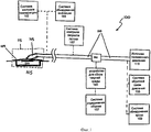
Фиг.1 иллюстрирует блок-схему устройства для приложения пониженного давления к участку ткани в соответствии с иллюстративным вариантом выполнения настоящего изобретения;Figure 1 illustrates a block diagram of a device for applying reduced pressure to a tissue site in accordance with an illustrative embodiment of the present invention;
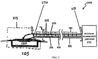
Фиг.2 иллюстрирует блок-схему устройства для приложения пониженного давления к участку ткани в соответствии с иллюстративным вариантом выполнения настоящего изобретения;Figure 2 illustrates a block diagram of a device for applying reduced pressure to a tissue site in accordance with an illustrative embodiment of the present invention;
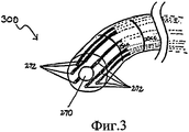
Фиг.3 иллюстрирует разрез элементов устройства для приложения пониженного давления к участку ткани в соответствии с иллюстративным вариантом выполнения настоящего изобретения;Figure 3 illustrates a section of elements of a device for applying reduced pressure to a tissue site in accordance with an illustrative embodiment of the present invention;
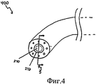
Фиг.4 иллюстрирует разрез элементов устройства для приложения пониженного давления к участку ткани в соответствии с иллюстративным вариантом выполнения настоящего изобретения;Figure 4 illustrates a section of elements of a device for applying reduced pressure to a tissue site in accordance with an illustrative embodiment of the present invention;
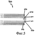
Фиг.5 иллюстрирует разрез элементов устройства для приложения пониженного давления к участку ткани в соответствии с иллюстративным вариантом выполнения настоящего изобретения;Figure 5 illustrates a section of elements of a device for applying reduced pressure to a tissue site in accordance with an illustrative embodiment of the present invention;
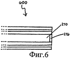
Фиг.6 иллюстрирует разрез элементов устройства для приложения пониженного давления к участку ткани в соответствии с иллюстративным вариантом выполнения настоящего изобретения;6 illustrates a section of elements of a device for applying reduced pressure to a tissue site in accordance with an illustrative embodiment of the present invention;
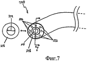
Фиг.7 иллюстрирует разрез элементов устройства для приложения пониженного давления к участку ткани в соответствии с иллюстративным вариантом выполнения настоящего изобретения;7 illustrates a section of elements of a device for applying reduced pressure to a tissue site in accordance with an illustrative embodiment of the present invention;
Фиг.8 иллюстрирует разрез элементов устройства для приложения пониженного давления к участку ткани в соответствии с иллюстративным вариантом выполнения настоящего изобретения;Fig. 8 illustrates a section through the elements of a device for applying reduced pressure to a tissue site in accordance with an illustrative embodiment of the present invention;
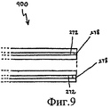
Фиг.9 иллюстрирует разрез элементов устройства для приложения пониженного давления к участку ткани в соответствии с иллюстративным вариантом выполнения настоящего изобретения;Fig.9 illustrates a section of the elements of the device for applying reduced pressure to a tissue site in accordance with an illustrative embodiment of the present invention;
Фиг.10 иллюстрирует блок-схему устройства для приложения пониженного давления к участку ткани в соответствии с иллюстративным вариантом выполнения настоящего изобретения;10 illustrates a block diagram of an apparatus for applying reduced pressure to a tissue site in accordance with an illustrative embodiment of the present invention;
Фиг.11 иллюстрирует вид в аксонометрии элементов устройства для приложения пониженного давления к участку ткани в соответствии с иллюстративным вариантом выполнения настоящего изобретения;11 illustrates a perspective view of elements of a device for applying reduced pressure to a tissue site in accordance with an illustrative embodiment of the present invention;
Фиг.12 иллюстрирует вид в аксонометрии элементов устройства для приложения пониженного давления к участку ткани в соответствии с иллюстративным вариантом выполнения настоящего изобретения;12 illustrates a perspective view of elements of a device for applying reduced pressure to a tissue site in accordance with an illustrative embodiment of the present invention;
Фиг.13 иллюстрирует вид в аксонометрии элементов устройства для приложения пониженного давления к участку ткани в соответствии с иллюстративным вариантом выполнения настоящего изобретения;13 illustrates a perspective view of elements of a device for applying reduced pressure to a tissue site in accordance with an illustrative embodiment of the present invention;
Фиг.14 иллюстрирует графическое представление системы для приложения пониженного давления к участку ткани в соответствии с иллюстративным вариантом выполнения настоящего изобретения;Fig. 14 illustrates a graphical representation of a system for applying reduced pressure to a tissue site in accordance with an illustrative embodiment of the present invention;
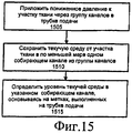
Фиг.15 иллюстрирует блок-схему, иллюстрирующую способ приложения пониженного давления к участку ткани в соответствии с иллюстративным вариантом выполнения настоящего изобретения;FIG. 15 is a flowchart illustrating a method of applying reduced pressure to a tissue site in accordance with an illustrative embodiment of the present invention; FIG.
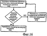
Фиг.16 иллюстрирует блок-схему, иллюстрирующую способ приложения пониженного давления к участку ткани в соответствии с иллюстративным вариантом выполнения настоящего изобретения.16 is a flowchart illustrating a method of applying reduced pressure to a tissue site in accordance with an illustrative embodiment of the present invention.
ПОДРОБНОЕ ОПИСАНИЕ ПРЕДПОЧТИТЕЛЬНОГО ВАРИАНТА ВЫПОЛНЕНИЯDETAILED DESCRIPTION OF THE PREFERRED EMBODIMENT
В последующем детальном описании предпочтительных вариантов выполнения делаются ссылки на сопровождающие чертежи, которые являются частью этого описания и на которых посредством иллюстрации показаны конкретные предпочтительные варианты выполнения, в которых может быть осуществлено изобретение. Эти варианты выполнения описаны достаточно подробно, чтобы позволить специалистам осуществить изобретение на практике, при этом подразумевается, что могут быть осуществлены и другие варианты выполнения и что могут быть выполнены логические, структурные, механические, электрические и химические изменения, не отступая от сущности или объема изобретения. Чтобы избежать деталей, не нужных специалистам для осуществления изобретения, в описании может быть опущена конкретная информация, известная специалистам. Последующее детальное описание не должно, поэтому, пониматься в ограничивающем смысле, при этом область настоящего изобретения определяется только приложенной формулой изобретения.In the following detailed description of the preferred embodiments, reference is made to the accompanying drawings, which are part of this description and which show by way of illustration specific preferred embodiments in which the invention may be practiced. These embodiments are described in sufficient detail to enable those skilled in the art to put the invention into practice, it being understood that other embodiments may be implemented and that logical, structural, mechanical, electrical and chemical changes can be made without departing from the spirit or scope of the invention . In order to avoid details not needed by those skilled in the art, specific information known to those skilled in the art may be omitted from the description. The following detailed description should not, therefore, be understood in a limiting sense, while the scope of the present invention is defined only by the attached claims.
Иллюстративные описанные здесь варианты выполнения предусматривают устройство и способ для приложения пониженного давления к участку ткани. Пониженное давление в целом относится к давлению, меньшему, чем давление окружающей среды на участке ткани, который подвергается лечению. В большинстве случаев это пониженное давление будет меньше, чем атмосферное давление в месте, в котором расположен пациент. Хотя термины «вакуум» и «отрицательное давление» могут быть использованы, чтобы описывать давление, приложенное к участку ткани, фактическое давление, приложенное к участку ткани, может быть значительно меньше, чем давление, обычно приписываемое полному вакууму. В соответствии с этим определением увеличение пониженного давления или вакуумного давления относится к относительному уменьшению абсолютного давления, тогда как уменьшение пониженного давления или вакуумного давления относится к относительному увеличению абсолютного давления. Точно так же пониженное давление, которое «меньше», чем конкретное пониженное давление, называют абсолютным давлением, которое больше, чем абсолютное давление, которое соответствует конкретному пониженному давлению. Кроме того, пониженное давление, которое «больше», чем конкретное пониженное давление, называют абсолютным давлением, которое меньше, чем абсолютное давление, которое соответствует конкретному пониженному давлению.The exemplary embodiments described herein provide a device and method for applying reduced pressure to a tissue site. Reduced pressure generally refers to pressure lower than the ambient pressure on the tissue site that is being treated. In most cases, this reduced pressure will be less than atmospheric pressure at the place where the patient is located. Although the terms “vacuum” and “negative pressure” can be used to describe the pressure applied to the tissue site, the actual pressure applied to the tissue site can be significantly less than the pressure usually attributed to full vacuum. According to this definition, an increase in reduced pressure or vacuum pressure refers to a relative decrease in absolute pressure, while a decrease in reduced pressure or vacuum pressure refers to a relative increase in absolute pressure. Similarly, a reduced pressure that is “less” than a particular reduced pressure is called an absolute pressure that is greater than an absolute pressure that corresponds to a particular reduced pressure. In addition, a reduced pressure that is “greater” than a particular reduced pressure is called an absolute pressure that is less than an absolute pressure that corresponds to a particular reduced pressure.
Устройство может содержать источник пониженного давления. Источник пониженного давления создает пониженное давление. В одном варианте выполнения устройство содержит трубку, имеющую группу каналов. Каналы содержат по меньшей мере один собирающий канал. Источник пониженного давления прикладывает пониженное давление к участку ткани через каналы таким образом, чтобы по меньшей мере в один собирающий канал поступала текучая среда от участка ткани. Указанный по меньшей мере один собирающий канал хранит текучую среду, полученную от участка ткани.The device may include a source of reduced pressure. The source of reduced pressure creates a reduced pressure. In one embodiment, the device comprises a tube having a group of channels. The channels comprise at least one collecting channel. The reduced pressure source applies reduced pressure to the tissue site through the channels so that at least one collecting channel receives fluid from the tissue site. The specified at least one collecting channel stores the fluid received from the tissue site.
В другом варианте выполнения устройство содержит индикатор, который выполнен с возможностью перемещения во множество положений. Например, индикатор может быть цилиндрическим индикатором, размещенным в кожухе, который присоединен между двумя частями трубки подачи. Трубка подачи может использоваться для подачи пониженного давления к участку ткани. В одном примере индикатор перемещается во втянутое положение из указанного множества положений в присутствии пониженного давления из источника пониженного давления. К индикатору может быть присоединен выполненный с возможностью сжатия элемент. Как используется здесь в дальнейшем, термин «соединенный» включает соединение через отдельный объект. Например, выполненный с возможностью сжатия элемент может быть соединен с индикатором, если и оба набора фильтров, и трубка соединены с третьим объектом. Термин «соединенный» также включает значение «непосредственно соединенный», когда два объекта касаются друг друга некоторым образом. Термин «соединенный» также охватывает два или большее количество элементов, которые непрерывны друг с другом, в том смысле, что каждый из элементов выполнен из одной и той же части материала. Выполненный с возможностью сжатия элемент может прикладывать силу смещения к индикатору в направлении выдвинутого положения из множества положений.In another embodiment, the device comprises an indicator that is configured to move to a variety of positions. For example, the indicator may be a cylindrical indicator located in a casing that is connected between two parts of the feed tube. The feed tube may be used to deliver reduced pressure to the tissue site. In one example, the indicator moves to a retracted position from a specified set of positions in the presence of reduced pressure from a source of reduced pressure. A compressible element may be attached to the indicator. As used hereinafter, the term "connected" includes a connection through a separate object. For example, a compressible member may be connected to an indicator if both sets of filters and the tube are connected to a third object. The term “connected” also includes the meaning “directly connected” when two objects touch each other in some way. The term “connected” also encompasses two or more elements that are continuous with each other, in the sense that each of the elements is made of the same part of the material. The compression element may apply a biasing force to the indicator in the direction of the extended position from the plurality of positions.
Обращаясь теперь к Фиг.1, в соответствии с иллюстративным вариантом выполнения изображена система 100 лечения пониженным давлением, которая прикладывает пониженное давление к участку 105 ткани. Участок 105 ткани может быть физической тканью любого человека, животного или другого организма, включая костную ткань, жировую ткань, мышечную ткань, кожную ткань, сосудистую ткань, соединительную ткань, хрящ, сухожилия, связки или любую другую ткань. Хотя участок 105 ткани может включать рану, больную или дефектную ткань, участок ткани может также включать здоровую ткань, которая не поранена, не больна или не дефектна. Применение пониженного давления к участку 105 ткани может быть использовано для обеспечения дренажа эксудата и других жидкостей от участка 105 ткани, а также чтобы способствовать росту дополнительной ткани. В случае, в котором участок 105 ткани является участком раны, рост гранулированной ткани и удаление эксудатов и бактерий способствуют исцелению раны. Применение пониженного давления к не пораненной или не дефектной ткани, включая здоровую ткань, может быть использовано, чтобы способствовать росту ткани, которая может быть собрана и пересажена в другое местоположение ткани.Turning now to FIG. 1, in accordance with an illustrative embodiment, a reduced
Пониженное давление, которое приложено к участку 105 ткани, создается источником 110 пониженного давления. Источник 110 может быть насосом любого типа, которым управляют вручную, механически или электрически. Неограничивающие примеры источника 110 пониженного давления включают устройства, которые приводятся в действие запасенной энергией и которые способны к созданию пониженного давления. Примеры таких приводимых в действие запасенной энергией источников пониженного давления включают, без ограничения, насосы, приводимые в действие пьезоэлектрической энергией, энергией пружины, солнечной энергией, кинетической энергией, энергией, запасенной в конденсаторах, энергией сгорания и энергией, созданной в цикле Стерлинга или аналогичных циклах. Другие примеры источника 110 пониженного давления включают устройства, которые приводятся в действие вручную, такие как сильфонные насосы, перистальтические насосы, диафрагменные насосы, насосы с ротационными лопастями, линейные поршневые насосы, пневматические насосы, гидравлические насосы, ручные насосы, ножные насосы и активируемые вручную насосы, такие как используются с активируемыми вручную аэрозольными распылителями. Тем не менее, другие устройства и процессы, которые могут быть использованы или включены в источник 110 пониженного давления, включают шприцы, винтовой шпиндель, храповики, устройства, управляемые часовым механизмом, устройства, управляемые маятником, ручные генераторы, осмотические процессы, теплонагревающие процессы и процессы, в которых вакуумные давления создаются конденсацией.The reduced pressure that is applied to the
В другом варианте выполнения источник 110 пониженного давления может содержать насос, который приводится в действие химической реакцией. Таблетка, раствор, спрей или другой механизм доставки могут быть доставлены к насосу и использоваться для инициации химической реакции. Тепло, создаваемое химической реакцией, может быть использовано для приведения в действие насоса для создания пониженного давления. В другом варианте выполнения для приведения в действие насоса для создания пониженного давления используется находящийся под давлением газовый баллон, такой как баллон с CO2. В еще одном варианте выполнения источник 110 пониженного давления может быть насосом, управляемым от аккумулятора. Предпочтительно, насос использует небольшое количество мощности и способен к работе в течение длительного периода времени от одного заряда аккумулятора.In another embodiment, the reduced pressure source 110 may include a pump that is driven by a chemical reaction. A tablet, solution, spray or other delivery mechanism can be delivered to the pump and used to initiate a chemical reaction. The heat generated by the chemical reaction can be used to drive the pump to create a reduced pressure. In another embodiment, a pressurized gas cylinder, such as a CO 2 cylinder, is used to actuate the pump to create a reduced pressure. In yet another embodiment, the reduced pressure source 110 may be a battery driven pump. Preferably, the pump uses a small amount of power and is capable of operating for a long period of time on a single charge of the battery.
Источник 110 пониженного давления обеспечивает пониженным давлением участок 105 ткани через повязку 115. Повязка 115 содержит магистраль 120, которая может быть помещена рядом с участком 105 ткани или в контакте с ней. Магистраль 120 может быть биологически совместимым пористым материалом, который может быть помещен в контакт с участком 105 ткани и распределять пониженное давление по участку 105 ткани. Магистраль 120 может быть выполнена из пенопласта, марли, войлочной циновки или любого другого материала, подходящего для конкретного биологического применения. Магистраль 120 может содержать проточные каналы или проходы, чтобы облегчить распределение пониженного давления или текучих сред к участку 105 ткани или от него.The reduced pressure source 110 provides reduced pressure to the
В одном варианте выполнения магистраль 120 представляет собой пористый пенопласт и содержит большое количество связанных ячеек или пор, которые действуют как проточные каналы. Пористый пенопласт может быть сетчатым пенополиуретаном с открытыми ячейками, таким как GranuFoam, изготовляемым компанией Kinetic Concepts, Inc. из Сан-Антонио, Техас. Если используется пенопласт с открытыми ячейками, то пористость может изменяться, но предпочтительно имеет значение приблизительно между 400 и 600 микронов. Проточные каналы обеспечивают проточное сообщение повсюду в части магистрали 120, имеющей открытые ячейки. Ячейки и проточные каналы могут быть однородными по форме и размеру или могут содержать структурные или случайные изменения по форме и размеру. Изменения в форме и размере ячеек магистрали сказываются на изменениях в проточных каналах, при этом такие характеристики могут быть использованы для изменения характеристик потока текучей среды через магистраль 120.In one embodiment,
Магистраль 120 может также быть изготовлена из саморассасывающихся материалов, которые не надо удалять из тела пациента после использования системы 100 лечения пониженным давлением. Подходящие саморассасывающиеся материалы могут включать, без ограничения, полимерную смесь полимолочной кислоты (ПМК) и полигликольной кислоты (ПГК). Полимерная смесь может также включать, без ограничения, поликарбонаты, полифумараты и капралактоны. Магистраль 120 может далее служить каркасом для роста новых клеток или каркасный материал может быть использован совместно с магистралью 120, чтобы способствовать росту клеток. Каркас представляет собой вещество или структуру, используемую для увеличения или способствования росту ячеек или формирования ткани, как, например, трехмерная пористая структура, которая обеспечивает матрицу для роста клеток. Иллюстративные примеры каркасных материалов включают фосфат кальция, коллаген, ПМК/ПГК, коралл гидрокси апатиты, карбонаты или обработанные материалы аллотрансплантата. В одном примере каркасный материал имеет высокую фракцию пустот (то есть высокое содержание воздуха).The
Повязка 115 также содержит уплотнительный элемент 125. Магистраль 120 может быть прикреплена к участку 105 ткани с использованием уплотнительного элемента 125. Уплотнительный элемент 125 может быть покрытием, которое используется для закрепления магистрали 120 на участке 105 ткани. В то время как уплотнительный элемент 125 может быть непроницаемым или полупроницаемым, в одном примере уплотнительный элемент 125 способен к поддержанию пониженного давления на участке 105 ткани после установки уплотнительного элемента 125 поверх магистрали 120. Уплотнительный элемент 125 может быть гибкой салфеткой или пленкой, выполненной из состава, основанного на силиконе, акрилате, гидрогеле или формирующем гидрогель материале, или любом другом биологически совместимом материале, который имеет характеристики непроницаемости или проницаемости, требуемые для участка 105 ткани. Уплотнительный элемент 125 может быть выполнен из гидрофобного материала, чтобы предотвратить поглощение влажности уплотнительным элементом 125.The dressing 115 also includes a sealing
Вместо того чтобы быть выполненным в форме «листа», такой как форма салфетки, уплотнительный элемент 125 может быть выполнен в «наливаемой» или «распыляемой» форме, которая применяется к магистрали 120 после размещения магистрали 120 в контакте с участком 105 ткани. Точно так же уплотнительный элемент 125 может содержать устройство, которое помещают на магистраль 120 и участок 105 ткани, чтобы обеспечить герметизирующие функциональные возможности, включая, но не ограничиваясь, аспирационную насадку, гипсовую повязку и вакуумный колпак.Instead of being in the form of a “sheet”, such as a napkin shape, the sealing
В одном варианте выполнения уплотнительный элемент 125 предназначен для создания уплотнительного соединения с тканью, окружающей магистраль 120 и участок 105 ткани. Уплотнительное соединение может быть образовано пластырем, помещенным вдоль периметра уплотнительного элемента 125 или на любой части уплотнительного элемента 125, чтобы закрепить уплотнительный элемент 125 на магистрали 120 или на ткани, окружающей участок 105 ткани. Пластырь может быть предварительно помещен на уплотнительном элементе 125, или может быть распылен, или иным способом нанесен на уплотнительный элемент 125 непосредственно до монтажа уплотнительного элемента 125.In one embodiment, the sealing
В некоторых случаях уплотнительный элемент 125 не обязательно должен герметизировать участок 105 ткани. Например, участок 105 ткани может быть способным к «самогерметизации», чтобы поддерживать пониженное давление. В случае подкожных и глубоких ран ткани, каверн и свищей поддержание пониженного давления на участке 105 ткани может быть возможным без использования уплотнительного элемента 125. Так как ткань часто включает или окружает эти типы участков ткани, ткань, окружающая указанный участок ткани, эффективно действует в качестве герметизирующего элемента.In some cases, the sealing
Пониженное давление, создаваемое источником 110 пониженного давления, может быть приложено к участку 105 ткани, используя трубку 135 подачи. Трубка 135 может быть любой трубкой, через которую могут протекать газ, жидкость, гель или другая текучая среда. Например, эксудат от участка 105 ткани может протекать через трубку 135. На Фиг.1 соединитель 150 соединяет трубку 135 с устройством 140 для сбора текучей среды. Однако трубка 135 может непосредственно соединять источник 110 пониженного давления с повязкой 115 без вмешательства в соединитель 150 или устройство 140 для сбора текучей среды.The reduced pressure created by the reduced pressure source 110 may be applied to the
Трубка 135 может иметь поперечное сечение любой формы, такой как круг, овал или многоугольник. Кроме того, трубка 135 может быть выполнена из любого материала и может быть либо гибкой, либо негибкой. Кроме того, трубка 135 может включать один или большее количество проходов или каналов, через которые может протекать текучая среда. Например, трубка 135 может включать два канала. В этом примере один канал может использоваться для прохода эксудата от участка 105 ткани к устройству 140 для сбора текучей среды. Другой канал может использоваться для подачи текучих сред, таких как воздух, антибактериальные агенты, противовирусные средства, агенты, способствующие росту клеток, ирригационные жидкости или другие химически активные агенты, к участку 105 ткани. Источник текучей среды, из которого проистекают эти жидкости, не показан на Фиг.1.The
В одном варианте выполнения трубка 135 включает подающий канал и один или большее количество собирающих каналов, предназначенных для сбора эксудата от участка 105 ткани. Каждый из этих каналов может также содержать фильтр, предназначенный для управления потоком эксудата через каналы. Дополнительные подробности относительно включения подающих каналов, собирающих каналов и фильтров в трубке 135 приведены ниже на Фиг.2-10.In one embodiment,
В одном варианте выполнения трубка 135 присоединена к магистрали 120 через соединительный элемент 145. Соединительный элемент 145 обеспечивает проход жидкости от магистрали 120 к трубке 135 и наоборот. Например, эксудаты, собранные от участка 105 ткани с использованием магистрали 120, могут войти в трубку 135 через соединительный элемент 145. В другом варианте выполнения система 100 лечения пониженным давлением не содержит соединительного элемента 145. В этом варианте выполнения трубка 135 может быть вставлена непосредственно в уплотнительный элемент 125 или магистраль 120 таким образом, чтобы конец трубки 135 был расположен рядом или в контакте с магистралью 120.In one embodiment,
Система 100 лечения пониженным давлением содержит устройство 140 для сбора текучей среды. Жидкость, такая как эксудат, может протекать через трубку 135 от участка 105 ткани в устройство 140. Устройство 140 может быть любым устройством или полостью, выполненной с возможностью содержания текучей среды, такой как газы и жидкости, а также текучих сред, которые содержат твердые частицы. Например, контейнер 115 может содержать эксудаты от участка 105 ткани. Трубка 130 источника и трубка 135 могут быть непосредственно соединены с устройством 140 или могут быть соединены с устройством 140 через соединитель, такой как соединитель 150.The reduced
Устройство 140 может представлять собой гибкий или твердый контейнер, сумку или мешок, проточно сообщающийся с магистралью 120 через трубку 135, Устройство 140 может быть отдельным контейнером или может быть функционально объединен с источником 110 пониженного давления, чтобы собирать эксудат и текучие среды. В иллюстративном варианте выполнения, в котором в качестве источника 110 пониженного давления используется ручной насос, такой как сильфонный насос, камера с переменным объемом, которая создает пониженное давление, может также служить устройством 140 для сбора текучей среды, собирая текучую среду по мере расширения камеры. Устройство 140 может содержать одну единственную камеру для сбора текучих сред или, в качестве альтернативы, может содержать несколько камер. Для захвата текучей среды или управления ей, когда она собрана, внутри контейнера 140 может быть помещен влагопоглотитель или абсорбирующий материал. В отсутствие устройства 140 для сбора текучей среды может быть использован способ для управления эксудатом и другими текучими средами, в котором текучие среды, особенно те, которые являются растворимыми водой, могут испаряться из магистрали 120. В другом варианте выполнения вместо устройства 140 для сбора текучей среды или в дополнение к нему может быть использован один или большее количество собирающих каналов в трубке 135, которые будут описаны ниже на Фиг.2-10.The device 140 may be a flexible or rigid container, bag or bag, in fluid communication with the
Система 100 лечения пониженным давлением может также содержать систему 155 обратной связи давления, функционально связанную с другими элементами системы 100, чтобы обеспечить пользователя информацией о системе 100, которая указывает на относительную или абсолютную величину давления, которое подано на участок 105 ткани или которое создается источником 110 пониженного давления. Примеры систем обратной связи включают, без ограничения, предохранительные клапаны, которые активируются, когда пониженное давление повышается выше заданного значения, и отклоняющие предохранительные клапаны. Дополнительные детали относительно систем обратной связи, которые содержат предохранительные клапаны и, в частности, подвижные индикаторы, которые откликаются на пониженное давление в трубке 135, приведены на Фиг.11-14.The reduced
Другие неограничивающие примеры систем обратной связи включают электронные индикаторы низкой мощности, приводимые в действие малогабаритными аккумуляторными элементами, шкальные индикаторы, которые отображают конкретные значения давления, которые приложены к участку ткани, полимеры с различными характеристиками отклонения и пленки, которые перемещаются относительно друг друга для создания визуальной индикации, указывающей на относительное или абсолютное значение давления, создаваемого системой 100. Пример системы, основанной на пленке, может включать желтую пленку, прикрепленную к первой части источника 110, которая выполнена с возможностью перемещения относительно синей пленки, прикрепленной ко второй части. Когда первая и вторая части перемещаются относительно друг друга, чтобы приложить пониженное давление, желтая и синяя пленки накладываются друг на друга, образуя зеленый индикатор. По мере увеличения давления и перемещения пленок друг от друга, исчезновение зеленого цвета указывает на то, что давление увеличилось (т.е. должно быть приложено больше пониженного давления).Other non-limiting examples of feedback systems include low power electronic indicators driven by small-sized battery cells, scale indicators that display specific pressure values applied to a tissue site, polymers with different deflection characteristics, and films that move relative to each other to create a visual indications indicating the relative or absolute value of the pressure generated by the
Система 100 лечения пониженным давлением может дополнительно содержать систему 157 определения объема, предназначенную для определения количества текучей среды, находящейся в устройстве 140, систему 159 обнаружения крови, предназначенную для определения наличия крови в эксудате, оттянутом из участка 105 ткани, систему 162 контроля температуры, предназначенную для осуществления контроля температуры участка 105 ткани, систему 165 обнаружения инфекции, предназначенную для определения наличия инфекции на участке 105 ткани, и систему 167 контроля скорости потока, предназначенную для осуществления контроля за расходом текучих сред, оттянутых из участка 105 ткани. Система 165 обнаружения инфекции может содержать пену или другое вещество, которое изменяет цвет в присутствии бактерий. Пена или другое вещество могут быть функционально связаны с магистралью 120 или трубкой 135 таким образом, чтобы изменяющий цвет материал был подвержен воздействию эксудата от участка 105 ткани. В дополнение к вышеупомянутым элементам и системам система 100 может содержать клапаны, регуляторы, выключатели и другие электрические, механические и текучие составляющие, чтобы облегчить применение лечения пониженным давлением к участку 105 ткани.The reduced
Обращаясь теперь к Фиг.2, в соответствии с иллюстративным вариантом выполнения показана система 200 лечения пониженным давлением, которая представляет собой неограничивающий пример системы 100 лечения пониженным давлением, изображенной на Фиг.1. В одном варианте выполнения устройство 140 для сбора текучей среды, изображенное на Фиг.1, представляет собой трубку 235, проточно присоединенную между повязкой 215 и источником 210 пониженного давления. Повязка 215 и источник 210 пониженного давления представляют собой неограничивающие примеры соответственно повязки 115 и источника 110 пониженного давления, изображенных на Фиг.1.Turning now to FIG. 2, in accordance with an illustrative embodiment, a reduced
Трубка 235 имеет группу каналов. В частности, трубка 235 содержит подающий канал 270 и группу собирающих каналов 272. Хотя на Фиг.2 изображена трубка 235 как имеющая один единственный подающий канал 270 и два собирающих канала 272, трубка 235 может иметь любое число подающих каналов и собирающих каналов. Например, многочисленные подающие каналы и один единственный собирающий канал могут быть включены в трубку 235.
Все каналы в трубке 235, включая подающий канал 270 и группу собирающих каналов 272, проточно соединены с источником 210 пониженного давления таким образом, что все они подвержены воздействию пониженного давления. Таким образом, пониженное давление, создаваемое источником 210 пониженного давления, может быть передано через каждый канал в трубке 235 к участку 205 ткани через повязку 215. В одном варианте выполнения источник 210 пониженного давления прикладывает пониженное давление к участку 205 ткани через подающий канал 270 и группу собирающих каналов 272 таким образом, что в собирающие каналы 272 поступает текучая среда 274, такая как жидкость или жидкость, содержащая твердые частицы от участка 205 ткани. В одном примере текучая среда 274 представляет собой эксудат от участка 205 ткани. Собирающие каналы 272 могут хранить текучую среду 274, полученную от участка 205 ткани. Таким образом, отпадает необходимость в отдельном устройстве для сбора текучей среды, таком как устройство 140 для сбора текучей среды, изображенное на Фиг.1.All channels in the
Система 200 лечения пониженным давлением может содержать по меньшей мере один фильтр, присоединенный к трубке 235. В частности, трубка 235 содержит фильтр 276 подающего канала и фильтр 278 собирающего канала. Фильтры 276 и 278 предотвращают прохождение или протекание текучей среды 274 от участка 205 ткани за указанное одно или большее количество мест, в которых расположены фильтры. Фильтры 276 и 278 могут быть фильтрами любого типа, способными к предотвращению потока текучей среды 274, такими как гидрофобный фильтр, гидрофильный фильтр и механический клапан. В примере, в котором фильтр 276 или фильтр 278 представляет собой механический клапан, может быть использован односторонний клапан, такой как клапан с качающейся головкой.The reduced
Фильтр 276 соединен с концом трубки 235, который расположен смежно с участком 205 ткани и повязкой 215. Используемый здесь термин «смежно» означает у или вблизи другого объекта. В одном примере первый объект может быть смежным с конкретным объектом, если первый объект ближе к конкретному объекту, нежели второй объект. Таким образом, первый конец трубки 235 может быть расположен смежно с участком 205 ткани, если первый конец трубки расположен ближе к участку 205 ткани, чем второй конец трубки. Фильтр 276 ограничивает или препятствует поступлению текучей среды 274 в подающий канал 270 через повязку 215. Таким образом, пониженное давление может непрерывно прикладываться через канал 270 без помех со стороны текучей среды 274, даже если текучая среды 274 собрана в собирающие каналы 274.A
Хотя на Фиг.2 фильтр 276 изображен препятствующим поступлению любой текучей среды 274 в канал 270, фильтр 276 может также быть размещен, чтобы препятствовать прохождению текучей среды 274 через конкретное место вдоль канала 270. Например, фильтр 276 может быть размещен в канале 270 на определенном расстоянии от конца трубки 235 таким образом, чтобы текучая среда 274 могла входить в часть канала 270 без помех со стороны фильтра 276. Дополнительные подробности относительно размещения и соединения фильтр 276 показаны на Фиг.4-6.Although FIG. 2 shows a
Фильтр 278 собирающего канала соединен с концом трубки 235, который расположен смежно с источником 210 пониженного давления. Фильтр 278 собирающего канала препятствует поступлению текучей среды 274 в источник 210 пониженного давления или выходу ее из собирающих каналов 272. Благодаря месту расположения фильтра 278 собирающего канала собирающие каналы 272 между повязкой 215 и фильтром 278 собирающего канала представляют собой резервуары, выполненные с возможностью получения эксудата и других текучих сред от участка 205 ткани. Поскольку собирающие каналы 272 находятся под влиянием источника 210 пониженного давления, текучие среды оттягиваются от участка 205 ткани через магистраль 220, которая расположена смежно с участком 205 ткани, в собирающие каналы 272. Объем места, доступного для жидкости, зависит от диаметра и числа собирающих каналов из группы собирающих каналов 272, а также от длины каждого собирающего канала между повязкой 215 и фильтром 278 собирающего канала. Например, собирающие каналы 272 могут быть выполнены с возможностью удержания приблизительно от 30 до 60 кубических сантиметров текучей среды 274. Однако вышеупомянутые физические параметры собирающих каналов 272 могут быть отрегулированы, основываясь на конкретном выполнении таким образом, чтобы собирающие каналы 272 могли удерживать любое количество текучей среды 274.The collecting
Когда собирающие каналы 272 заполняются текучей средой, они все еще способны к передаче пониженного давления из источника 210 пониженного давления. Когда собирающие каналы 272 полностью заполнены текучей средой 274 между повязкой 215 и фильтром 278, пониженное давление больше, возможно, не может передаваться через собирающие каналы 272. Однако подающий канал 270 продолжает передавать пониженное давление даже после того, как собирающие каналы 272 заполнились.When the collecting
Хотя фильтр 278 собирающего канала изображен как присоединенный к концу трубки 235, расположенному смежно с источником 210 пониженного давления, фильтр 278 может быть расположен в любом месте вдоль трубки 235. Например, фильтр 278 может быть расположен в середине вдоль длины трубки 235. В этом примере собирающие каналы 272 могут заполняться текучей средой 274 до тех пор, пока прохождение текучей среды 274 не будет затруднено фильтром 278 в середине трубки 235. Таким образом, фильтр 278 собирающего канала препятствует тому, чтобы текучая среда 274 проходила через середину трубки 235 вдоль собирающих каналов 272. В этом примере только часть пространства, ограниченного собирающими каналами 272, может заполняться текучей средой 274.Although the collecting
В другом примере система 200 лечения пониженным давлением может содержать группу фильтров собирающего канала. В этом примере каждый фильтр собирающего канала может быть расположен в разных местах вдоль каждого собирающего канала из группы собирающих каналов 272. Таким образом, каждый собирающий канал из группы собирающих каналов 272 может иметь различную емкость для текучей среды.In another example, the reduced
Поскольку система 200 лечения пониженным давлением может быть использована для лечения участков ткани с малым выходом эксудата, меньший собирающий объем текучей среды, обеспечиваемый собирающими каналами 272 (в отличие от специального контейнера), имеет небольшой эффект или никакого эффекта на способность системы 200 осуществлять лечение в течение длительного периода времени. Компактная природа устройства, собирающего текучую среду, которое интегрировано в трубку подачи пониженного давления, сводит к минимуму дискомфорт пациента и максимизирует его подвижность. Во время лечения, когда собирающие каналы 272 полностью наполняются текучей средой 274, трубка 235 может быть легко заменена новой трубкой. Чтобы свести к минимуму риск проливания текучей среды во время замены трубок или чтобы получить обратный поток текучей среды в магистраль 220 во время лечения, собирающие каналы 272 могут быть частично заполнены или упакованы влагопоглотителями, абсорбирующими материалами или другими захватывающими агентами.Since the reduced
На Фиг.2 часть собирающих каналов 272, которые содержат текучую среду 274, заштрихованы, чтобы показать, что текучая среда 274 видна пользователю системы 200 лечения пониженным давлением. Трубка 235 может содержать по меньшей мере одну по существу прозрачную часть, через которую может быть видна текучая среда 274. Например, указанная одна или более одной по существу прозрачных частей трубки могут представлять собой окно на трубке 235, выполненное из прозрачного материала. Каждое из этих окон может проходить поперек частей трубки 235, которые расположены смежно с каждым соответствующим собирающим каналом 272.2, a portion of the
В другом примере материал, из которого изготовлена трубка 235, может быть прозрачным материалом. Таким образом, текучая среда 274 может быть видна благодаря полной прозрачности трубки 235. Поскольку текучая среда 274 от участка 205 ткани, такая как эксудат, может иметь темный цвет, уровни текучей среды во множестве собирающих каналов 272 могут быть легко определены пользователем.In another example, the material from which the
Трубка 235 также содержит метки 280. Метки 280 указывают на количество текучей среды 274 в группе собирающих каналов 272. В примере, в котором трубка 235 содержит одну или большее количество по существу прозрачных частей, таких как прозрачные окна, метки 280 могут быть предусмотрены вдоль каждого окна. Каждая из меток 280 может соответствовать конкретному объему или количеству текучей среды 274. Например, первая из меток 280 может быть отмаркирована «5 куб.см», а каждая последующая метка может быть отмаркирована с приращением 5 кубических сантиметров. Конкретное используемое приращение может зависеть от применения.The
На Фиг.3 изображен разрез трубки 300, который показан в аксонометрии индикатора поперечного сечения, отмаркированного «Фиг.3», изображенного на Фиг.2. Как показано на Фиг.3, поперечное сечение подающего канала 270 больше, чем поперечное сечение каждого из собирающих каналов 272. Однако в одном примере поперечное сечение канала 270 может быть равно или меньше, чем поперечное сечение каждого из собирающих каналов 272. Канал 270 и собирающие каналы 272 также имеют круглое поперечное сечение. Однако канал 270 и собирающие каналы 272 могут иметь поперечное сечение любой формы, такой как овальная, многоугольная или неправильная форма.Figure 3 shows a section of a
Каждый из собирающих каналов 272 изображен равноудаленным от канала 270 таким образом, что собирающие каналы 272 окружают подающий канал 270 круговым образом. Однако канал 270 и собирающие каналы 272 могут иметь любую пространственную конфигурацию относительно друг друга, включая конфигурации, в которых каждый из собирающих каналов 272 расположен на различном расстоянии от канала 270. Кроме того, трубка 300 может содержать два или большее количество подающих каналов, таких как подающий канал 270. В трубку 300 также может быть включено любое число собирающих каналов 272. В одном примере число подающих каналов в трубке 300 превышает число собирающих каналов.Each of the collecting
Канал 270 также показан расположенным вдоль продольного центра трубки 300. Однако канал 270 может быть расположен вдоль любой продольной оси, которая проходит по длине трубки 300. В одном примере канал 270 и собирающие каналы 272 могут быть ограничены стенками, которые проходят по длине трубки 300. В этом примере две или больше двух пересекающихся стенок могут ограничивать сектора, любой из которых может быть подающим каналом или собирающим каналом.
На Фиг.4 изображен разрез трубки 400, который показан в аксонометрии индикатора поперечного сечения, отмаркированного «Фиг.4», изображенного на Фиг.2. Трубка 400 содержит фильтр 276 трубки подачи, который присоединен к трубке 400 в отверстии канала 270. Фильтр 276 может иметь одинаковое поперечное сечение с каналом 270 или немного большее поперечное сечение, чем канал 270, чтобы гарантировать, что фильтр 276 сможет препятствовать поступлению текучей среды в канал 270. Фильтр 276 может быть соединен с концом трубки 400 с использованием любого способа. Например, фильтр 276 может быть приварен, привернут, приклеен, посажен на болты, герметично закрыт, защелкнут или запрессован на конец трубки 400.Figure 4 shows a section of a
На Фиг.5 изображен разрез трубки 500, который показан в аксонометрии индикатора поперечного сечения, отмаркированного «Фиг.5», изображенного на Фиг.4. Фиг.5 показывает отверстие канала 270, прохождение через которое затруднено фильтром 276 таким образом, что текучая среда от участка ткани не может войти в канал 270. Конкретнее, фильтр канала 270, как показано, расположен только за пределами канала 270 таким образом, что фильтр канала 270 выступает за диаметр канала 270 в выступающих частях 277. Фильтр 276 может иметь любую толщину, достаточную для предотвращения потока текучей среды в канал 270. Прохождение через отверстия собирающих каналов 272 не затруднено фильтром 276, так что текучая среда может быть принята и собрана собирающими каналами 272.Figure 5 shows a section of a
На Фиг.6 показан разрез трубки 600, на котором размер и конструкция фильтра 276 отличается от размера и конструкции фильтра канала 276, изображенного на Фиг.5. Конкретнее, диаметр фильтра 276 приблизительно равен диаметру трубки 270 подачи, так что фильтр 276 встает в место, ограниченное каналом 270. Хотя фильтр 276 показан размещенным в конце канала 270, фильтр 276 может быть расположен в любом месте вдоль канала 270. В этом примере фильтр 276 предотвращает прохождение жидкости от места участка ткани, в котором вдоль канала 270 расположен его фильтр 276.FIG. 6 shows a section through a
На Фиг.7 изображен разрез трубки 700, который показан в аксонометрии индикатора поперечного сечения, отмаркированного «Фиг.7», изображенного на Фиг.2. Трубка 700 содержит фильтр 278 собирающего канала. Фильтр 278 собирающего канала показан присоединенным к концу трубки 700. Фильтр 278 собирающего канала также показан отсоединенным от конца трубки 700, чтобы лучше показать форму фильтра собирающего канала. Фильтр 278 собирающего канала представляет собой диск, имеющий отверстие 279. Когда фильтр 278 присоединен к концу трубки 700, он закрывает собирающие каналы 272, но не закрывает канал 270, поскольку отверстие 279 расположено в месте расположения отверстия канала 270. Таким образом, фильтр 278 собирающего канала может обеспечивать выход текучей среды, которая была собрана фильтром 278 собирающего канала из собирающих каналов 272, и поступление ее в источник пониженного давления, такой как источник 210 пониженного давления, изображенный на Фиг.2. Однако пониженное давление все еще может быть приложено через фильтр 278 собирающего канала, так что собирающие каналы 272 могут передавать пониженное давление к участку ткани. Хотя фильтр 278 собирающего канала показан имеющим «O»-образную форму, фильтр 278 собирающего канала может иметь любую форму, которая способна воспрепятствовать выходу жидкости из одного или нескольких собирающих каналов 272.Figure 7 shows a section of a
Фильтр 278 собирающего канала может быть присоединен к концу трубки 700 с использованием любого способа. Например, фильтр 278 собирающего канала может быть приварен, привернут, приклеен, посажен на болты, герметично закрыт, защелкнут или запрессован на конец трубки 700.The collecting
На Фиг.8 изображен разрез трубки 500, который показан в аксонометрии индикатора поперечного сечения, отмаркированного «Фиг.8», изображенного на Фиг.7. На Фиг.8 показано, что прохождение через отверстие собирающих каналов 272 затруднено фильтром 278 собирающего канала таким образом, что жидкость от участка ткани не может выйти из собирающих каналов 272 или войти в источник пониженного давления. В частности, фильтр 278 показан расположенным снаружи собирающих каналов 272 рядом с ними таким образом, что он выступает за каждый диаметр каждого собирающего канала 272. Фильтр 278 может иметь любую толщину, достаточную для предотвращения потока текучей среды из собирающих каналов 278. Прохождение через отверстие канала 270 не затруднено фильтром 278, так что между отверстием канала 270 и источником пониженного давления не существует никаких помех.On Fig shows a section of the
На Фиг.9 изображен разрез трубки 900, на котором размер и конфигурация фильтра 278 собирающего канала отличаются от размера и конфигурации фильтра 278 собирающего канала, изображенного на Фиг.8. В частности, фильтр 278 содержит несколько фильтров собирающего канала, каждый из которых расположены внутри пространства, ограниченного собирающими каналами 272. Диаметр каждого фильтра 278 приблизительно равен диаметру каждого собирающего канала 272, так что фильтры 278 помещены в собирающие каналы 272. В этом примере каждый из фильтров собирающего канала может представлять собой механический клапан, который предотвращает поток жидкости, такой как эксудат, но не предотвращают поток газа, обеспечивая, тем самым, поток пониженного давления через фильтры 278. Хотя фильтры 278 показаны расположенными в концах каждого собирающего канала 272, фильтры 278 могут быть расположены в любом месте по длине собирающих каналов 272, ограничивая, таким образом, емкость для текучей среды для каждого собирающего канала. Каждый фильтр 278 собирающего канала может также быть расположен в различных местах вдоль каждого соответствующего собирающего канала 272 так, чтобы каждый собирающий канал 272 имел различную емкость для текучей среды.FIG. 9 is a sectional view of a
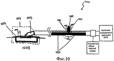
Обращаясь теперь к Фиг.10, в соответствии с иллюстративным вариантом выполнения показана система 1000 лечения пониженным давлением, которая представляет собой неограничивающий пример системы 100 лечения пониженным давлением, изображенной на Фиг.1. В частности, система 1000 включает неограничивающий пример системы 155 обратной связи пониженного давления, изображенной на Фиг.1. Система 1000 содержит источник 1010 пониженного давления, который создает пониженное давление, которое может быть приложено к участку 1005 ткани.Turning now to FIG. 10, in accordance with an illustrative embodiment, a reduced
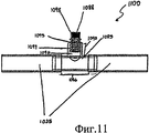
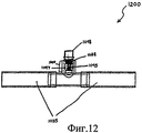
Система 1000 лечения пониженным давлением также содержит кожух 1000 индикатора, который расположен между двумя частями трубки 1035 подачи. Трубка 1035 представляет собой неограничивающий пример трубки 135 подачи, изображенной на Фиг.1. Кожух 1000 индикатора содержит соединительную часть 1086. Соединительная часть 1086 передает пониженное давление от одной части трубки 1035 к другой части трубки 1035. Соединительная часть 1086 также имеет такое же или похожее значение пониженного давления, что и трубка 1035. Кожух 1000 индикатора содержит индикатор 1088, который присоединен с возможностью скольжения к отверстию вдоль части 1090 трубки кожуха 1085 индикатора. Индикатор 1088 может иметь цилиндрическую форму. Индикатор 1088 может иметь овальную или многоугольную форму поперечного сечения. Индикатор 1088 может также иметь любой цвет, такой как красный, оранжевый или желтый.The reduced
Индикатор 1088 откликается на величину пониженного давления, присутствующего в системе 1000 лечения пониженным давлением таким образом, чтобы пользователь мог определить, требуемое или терапевтическое значение пониженного давления прикладывается к участку ткани 1005. В частности, индикатор 1088 выполнен с возможностью перемещения в несколько положений вдоль оси 1092. Несколько положений может включать втянутое положение. Во втянутом положении индикатор 1088 может быть полностью или частично втянут в часть 1090 трубки таким образом, что индикатор 1088 частично или полностью невидим для пользователя. Множество положений может также включать выдвинутое положение. На Фиг.10 индикатор 1088 показан в выдвинутом положении. В выдвинутом положении индикатор 1088 может полностью или частично выступать из части 1090 трубки таким образом, чтобы индикатор 1088 был видим для пользователя. Множество положений может также включать любое положение между полностью выдвинутым положением и полностью втянутым положением.The
Система 1000 лечения пониженным давлением также содержит сжимаемый элемент, такой как пружина, которая присоединена к индикатору 1088 и расположена в части 1090 трубки. Сжимаемый элемент не показан на Фиг.10, но будет описан более подробно на Фиг.11 и 12. Сжимаемый элемент прикладывает силу смещения к индикатору 1088, который смещает индикатор 1088 к его выдвинутому положению. Сила смещения приложена в направлении, обозначенном стрелкой 1093.The reduced
Хотя кожух 1085 индикатора изображен расположенным между двумя частями трубки 1035, кожух 1085 индикатора может быть расположен в любом месте в системе 1000 лечения пониженным давлением, в котором пониженное давление, приложенное к участку ткани 1005, может быть определено. Например, кожух 1085 индикатора наряду с индикатором 1088 может быть расположен в любом месте повязки 1015, включая уплотнительный элемент 1025 или соединитель 1045. Показанный пунктиром индикатор 1094 иллюстрирует пример, в котором кожух 1085 индикатора, наряду с индикатором 1088, расположен на уплотнительном элементе 1025. В другом примере кожух 1085 индикатора, наряду с индикатором 1088, может быть расположен на любом конце одной единственной трубки подачи, которая соединяет источник 1010 пониженного давления с повязкой 1015.Although the
В одном варианте выполнения индикатор 1088 перемещается во втянутое положение при наличии пониженного давления из источника 1010 пониженного давления. В частности, индикатор 1088 может переместиться во втянутое положение, когда в трубке 1035 и соединительной части 1086 имеется пониженное давление. При перемещении во втянутое положение индикатор 1088 должен преодолеть силу смещения, приложенную сжимаемым элементом в направлении, обозначенном стрелкой 1093. Достаточно высокое пониженное давление в соединительной части 1086 может преодолеть эту силу смещения и втянуть индикатор 1088 во втянутое положение. Величина пониженного давления, которая необходима для преодоления силы смещения, может зависеть от величины силы смещения, приложенной сжимаемым элементом. В примере, в котором сжимаемый элемент представляет собой витую пружину, коэффициент упругости витой пружины определяет величину пониженного давления, необходимого для втягивания индикатора 1088 во втянутое положение.In one embodiment,
В одном примере индикатор 1088 перемещается во втянутое положение, когда пониженное давление в трубке 1035 превышает первое пороговое пониженное давление. Первое пороговое пониженное давление может быть определено пользователем и может быть осуществлено путем изменения силы смещения, приложенной сжимаемым элементом. Например, пользователь может выбрать сжимаемый элемент с коэффициентом упругости пружины, который требует, чтобы пониженное давление в трубке 1035 превышало терапевтическое пониженное давление, чтобы индикатор 1088 мог быть втянут во втянутое положение. В одном варианте выполнения индикатор 1088 перемещается во втянутое положение, когда абсолютное давление, создаваемое источником пониженного давления, равно или меньше приблизительно 125 миллиметров ртутного столба. Таким образом, пользователь системы 1000 может быть в состоянии визуально определить, когда терапевтическое пониженное давление прикладывается к участку 1005 ткани путем наблюдения, что индикатор 1088 не выступает из части 1090 трубки.In one example, the
В другом варианте выполнения сжимаемый элемент может смещать индикатор 1088 в выдвинутое положение, когда пониженное давление в трубке 1035 меньше, чем второе пороговое пониженное давление. В одном примере первое пороговое пониженное давление такое же, что и второе пороговое пониженное давление. В другом примере первое пороговое пониженное давление отличается от второго порогового пониженного давления так, что индикатор находится в полностью втянутом положении, когда пониженное давление превышает первое пороговое пониженное давление и находится в полностью выдвинутом положении, когда пониженное давление меньше, чем второе пороговое пониженное давление. В этом варианте выполнения индикатор 1088 может находиться в промежуточном положении между полностью втянутым положением и полностью выдвинутым положением, когда пониженное давление находится между первым и вторым порогами пониженного давления.In another embodiment, the compressible member may bias the
В другом варианте выполнения сжимаемый элемент смещает индикатор 1088 в выдвинутое положение при отсутствии пониженного давления в трубке 1035. В одном примере отсутствие пониженного давления происходит из-за того, что источник 1010 пониженного давления выключен. Поскольку сжимаемый элемент в части 1090 трубки смещает индикатор 1088 так, чтобы тот выступал из части 1090 трубки, когда пониженное давление отсутствует или ниже порогового значения, пользователь может визуально определить, когда терапевтическое давление не приложено к участку ткани 1005, путем наблюдения, что индикатор 1088 выступает из части 1090 трубки. Пользователь может затем предпринять необходимые действия, чтобы приложить терапевтическое давление к участку 1005 ткани. Одной причиной, почему пониженное давление в трубке 1035 может отсутствовать или быть ниже порогового значения, являются утечки в трубке 1035 или в другом месте в системе 1000. При этих обстоятельствах пользователю сообщают о возможной утечке, когда индикатор 1088 находится в выдвинутом положении.In another embodiment, the compressible member biases the
Обращаясь теперь к Фиг.11, в соответствии с иллюстративным вариантом выполнения показана система 1100 обратной связи пониженного давления, такая как изображена на Фиг.10. В частности, индикатор 1088 в системе 1100 обратной связи пониженного давления находится в выдвинутом положении.Turning now to FIG. 11, in accordance with an illustrative embodiment, a reduced
Соединительная часть 1086 с возможностью скольжения взаимодействует с двумя частями трубки 1035 с образованием уплотнительной посадки. Соединительная часть 1086 кожуха 1085 индикатора может также с возможностью создания уплотнения взаимодействовать с двумя частями трубки 1035 множеством способов. Например, соединительная часть 1086 может быть приварена, привернута, приклеена, посажена на болты, герметично закрыта, защелкнута или запрессована на две части трубки 1035.The connecting
В системе 1100 обратной связи пониженного давления сжимаемый элемент представляет собой витую пружину. Часть 1090 трубки кожуха 1085 индикатора включает основание 1096, к которому присоединен конец витой пружины 1095. Однако конец пружины 1095, который не присоединен к индикатору 1088, может быть присоединен к любому другому элементу кожуха индикатора, вместе с которым витая пружина может быть использована для приложения силы смещения к индикатору 1088. Внутренняя поверхность части 1090 трубки представляет собой трубчатое отверстие, вдоль которого индикатор 1088 может скользить во втянутое и выдвинутое положения. Пружина 1095 удерживается гофрами 1097, которые являются частью трубчатой стенки. Гофры 1097 обеспечивают сжатие и расширение трубчатой стенки, не вызывая боковое напряжение к внутренней стенке части 1090.In the reduced
Система 1100 обратной связи пониженного давления также содержит крышку 1098. Крышка 1098 может быть выполнена из прозрачного материала, который позволяет пользователю рассматривать индикатор 1088, когда индикатор 1088 находится в выдвинутом положении. В одном примере крышка 1098 также с возможностью создания уплотнения взаимодействует с остальной частью кожуха 1085 индикатора так, чтобы пониженное давление не стравилось через трубчатое отверстие в кожухе 1085 индикатора.The reduced
Как описано выше, витая пружина 1095 может иметь любой коэффициент упругости. Коэффициент упругости пружины 1095 определяет силу смещения, которая прикладывается к индикатору 1088, смещая его к выдвинутому положению. В одном варианте выполнения пружина 1095 имеет такой коэффициент упругости, что она смещает индикатор 1088 в выдвинутое положение, когда абсолютное давление в трубке 1035 превышает приблизительно 125 миллиметров ртутного столба. Однако для смещения индикатора 1088 в выдвинутое положение могут также быть использованы другие витые пружины, имеющие другие коэффициенты упругости, когда абсолютное давление в трубке 1035 превышает другие пороги абсолютного давления, такие как требуемые пороги терапевтического давления.As described above, the
Обращаясь теперь к Фиг.12, в соответствии с иллюстративным вариантом выполнения показана система 1200 обратной связи пониженного давления, которая представляет собой неограничивающий пример системы 1100 обратной связи пониженного давления. В частности, система 1200 обратной связи пониженного давления показывает индикатор 1088, находящийся во втянутом положении. Когда индикатор 1088 находится во втянутом положении, пониженное давление от трубки 1035 передается индикатору 1088 через трубчатую стенку, образованную из гофров 1097. Это пониженное давление прикладывает тянущее усилие к индикатору 1088, которое достаточно для преодоления силы смещения, приложенной пружиной 1095 в противоположном направлении. Индикатор 1088, таким образом, вытягивается из прозрачной крышки 1098 и уходит из поля обозрения пользователя системы лечения пониженным давлением. Отсутствие индикатора 1088 в крышке 1098 указывает пользователю на то, что терапевтическое давление приложено к участку ткани. В другом варианте выполнения крышка 1098 может быть присоединена к индикатору 1088 таким образом, чтобы крышка 1098 также втягивалась в часть 1090 трубки, когда индикатор 1088 находится во втянутом положении.Turning now to FIG. 12, in accordance with an illustrative embodiment, a reduced
Обращаясь теперь к Фиг.13, в иллюстративном варианте выполнения показана система 1300 обратной связи пониженного давления, которая представляет собой неограничивающий пример системы обратной связи пониженного давления, изображенной на Фиг.10. Вид в аксонометрии, изображенный на Фиг.13, показывает круглое поперечное сечение индикатора 1088, крышки 1098, части 1090 трубки, а также отверстие 1099, через которое выступает индикатор 1088. Эти элементы, однако, могут иметь любую другую форму поперечного сечения, такую как овал или многоугольник.Turning now to FIG. 13, in an illustrative embodiment, a reduced
Обращаясь теперь к Фиг.14, в соответствии с иллюстративным вариантом выполнения показан график, иллюстрирующий соотношение между пониженным давлением в трубке 1035 и положением индикатора 1088. Как показано на графике 1400, при увеличении пониженного давления в трубке 1035 индикатор 1088 перемещается к полностью втянутому положению. В одном варианте выполнения индикатор 1088 перемещается к полностью втянутому положению линейным способом, как показано линией 1410 на графике. Соотношение между пониженным давлением и положением индикатора 1088 может также иметь другой характер, как обозначено линиями 1415 и 1420 на графике. Другой характер, такой как ступенчатый характер, может также характеризовать соотношение между пониженным давлением и положением индикатора 1088. В одном примере индикатор 1088 находится в полностью втянутом положении, когда пониженное давление соответствует абсолютному давлению в 125 миллиметров ртутного столба.Referring now to FIG. 14, in accordance with an illustrative embodiment, a graph illustrating the relationship between the reduced pressure in the
Обращаясь теперь к Фиг.15, в соответствии с иллюстративным вариантом выполнения проиллюстрирован способ, который может быть осуществлен системой лечения пониженным давлением, такой как система 200 лечения пониженным давлением, изображенная на Фиг.2. В способе прикладывают пониженное давление к участку ткани через каналы в трубке подачи (этап 1505). В способе сохраняют текучую среду от участка ткани по меньшей мере в одном собирающем канале из группы каналов (этап 1510). Определяют уровень текучей среды в указанном по меньшей мере одном собирающем канале, основываясь на множестве меток, выполненных на трубке подачи (этап 1515).Turning now to FIG. 15, in accordance with an illustrative embodiment, a method that can be implemented by a reduced pressure treatment system, such as a reduced
Обращаясь теперь к Фиг.16, в соответствии с иллюстративным вариантом выполнения проиллюстрирован способ, который может быть осуществлен системой лечения пониженным давлением, такой как система 1000 лечения пониженным давлением, изображенной на Фиг.10. В способе прикладывают пониженное давление к участку ткани, используя источник пониженного давления (этап 1605). Определяют, имеется ли пороговое значение пониженного давления в трубке подачи или в другом элементе системы лечения пониженным давлением (этап 1610). Если определяют, что пороговое значение пониженного давления отсутствует, индикатор перемещается в выдвинутое положение, используя сжимаемый элемент. Способ затем возвращается к этапу 1605. Возвращаясь к этапу 1610, если определяют, что присутствует пороговое значение пониженного давления, индикатор перемещается во втянутое положение (этап 1620).Turning now to FIG. 16, in accordance with an illustrative embodiment, a method that can be implemented by a reduced pressure treatment system, such as the reduced
Графики и блок-схемы в различных изображенных вариантах выполнения иллюстрируют общую картину, функциональные возможности и работу некоторых возможных применений устройства и способов. В некоторых альтернативных применениях функция или функции, отмеченные в блоке, могут происходить не в том порядке, отмеченном на чертежах. Например, в некоторых случаях два блока, показанные как следующие один за другим, могут быть выполнены по существу одновременно или же блоки могут иногда выполняться в обратном порядке, в зависимости от вовлеченных функциональных возможностей.The graphs and flowcharts in the various illustrated embodiments illustrate the overall picture, functionality, and operation of some of the possible applications of the device and methods. In some alternative applications, the function or functions indicated in the block may not occur in the order indicated in the drawings. For example, in some cases, two blocks, shown as following one after the other, can be executed essentially simultaneously or the blocks can sometimes be executed in the reverse order, depending on the functionality involved.
Claims (23)
источник пониженного давления, создающий пониженное давление, и трубку, имеющую группу каналов, включающую по меньшей мере один собирающий канал,
причем источник пониженного давления прикладывает пониженное давление к участку ткани через указанную группу каналов с обеспечением поступления текучей среды от участка ткани в указанный по меньшей мере один собирающий канал, в котором хранится эта текучая среда, полученная от участка ткани,
при этом указанный по меньшей мере один собирающий канал содержит абсорбирующий материал.1. A device for applying reduced pressure to a tissue site, containing:
a source of reduced pressure creating a reduced pressure, and a tube having a group of channels including at least one collecting channel,
moreover, the source of reduced pressure applies reduced pressure to the tissue site through the specified group of channels to ensure the flow of fluid from the tissue site to the specified at least one collecting channel in which this fluid received from the tissue site is stored,
wherein said at least one collecting channel comprises absorbent material.
подающий канал, который входит в указанную группу каналов, и фильтр подающего канала, расположенный в указанном по меньшей мере одном фильтре, причем фильтр подающего канала присоединен к подающему каналу и препятствует поступлению текучей среды в этот канал.4. The device according to claim 2, further comprising:
the supply channel, which is included in the specified group of channels, and the filter of the supply channel located in the specified at least one filter, and the filter of the supply channel is connected to the supply channel and prevents the flow of fluid into this channel.
приложение пониженного давления к участку ткани с использованием источника пониженного давления, который прикладывает пониженное давление к участку ткани через группу каналов в трубке подачи,
накопление текучей среды от участка ткани в по меньшей мере одном собирающем канале, входящем в указанную группу каналов, и
определение уровня текучей среды в указанном по меньшей мере одном собирающем канале, основываясь на метках, расположенных на трубке подачи.12. A method of applying reduced pressure to a tissue site, comprising:
applying reduced pressure to the tissue site using a reduced pressure source that applies reduced pressure to the tissue site through a group of channels in the feed tube,
accumulation of fluid from a tissue site in at least one collecting channel included in said channel group, and
determining a fluid level in said at least one collecting channel based on marks located on the supply tube.
источник пониженного давления, создающий пониженное давление,
индикатор, выполненный с возможностью перемещения во множество положений, причем индикатор перемещается во втянутое положение из указанного множества положений в присутствии пониженного давления из источника пониженного давления;
сжимаемый элемент, присоединенный к индикатору, причем сжимаемый элемент прикладывает силу смещения к индикатору в направлении выдвинутого положения из указанного множества положений; и
трубку подачи, причем источник пониженного давления прикладывает пониженное давление к участку ткани через трубку подачи, при этом индикатор перемещается в одно положение из указанного множества положений в зависимости от пониженного давления в трубке подачи.13. A device for applying reduced pressure to a tissue site, comprising:
source of reduced pressure, creating a reduced pressure,
an indicator configured to move to a plurality of positions, the indicator moving to a retracted position from said plurality of positions in the presence of reduced pressure from a source of reduced pressure;
a compressible element attached to the indicator, wherein the compressible element applies a biasing force to the indicator in the direction of the extended position from the specified plurality of positions; and
the supply tube, and the source of reduced pressure applies reduced pressure to the tissue site through the feed tube, while the indicator moves to one position from the specified set of positions depending on the reduced pressure in the feed tube.
приложение пониженного давления к участку ткани с использованием источника пониженного давления,
перемещение индикатора от выдвинутого положения из множества положений во втянутое положение из указанного множества положений, в присутствии порогового пониженного давления из источника пониженного давления.22. A method of applying reduced pressure to a tissue site, comprising:
applying reduced pressure to a tissue site using a reduced pressure source,
moving the indicator from an extended position from a plurality of positions to a retracted position from a specified plurality of positions, in the presence of a threshold reduced pressure from a source of reduced pressure.
Applications Claiming Priority (2)
| Application Number | Priority Date | Filing Date | Title |
|---|---|---|---|
| US90041507P | 2007-02-09 | 2007-02-09 | |
| US60/900,415 | 2007-02-09 |
Publications (2)
| Publication Number | Publication Date |
|---|---|
| RU2009123208A RU2009123208A (en) | 2011-03-20 |
| RU2459636C2 true RU2459636C2 (en) | 2012-08-27 |
Family
ID=39690676
Family Applications (1)
| Application Number | Title | Priority Date | Filing Date |
|---|---|---|---|
| RU2009123208/14A RU2459636C2 (en) | 2007-02-09 | 2008-02-08 | Apparatus and method for treating tissue region by applying low pressure |
Country Status (15)
| Country | Link |
|---|---|
| US (4) | US8057449B2 (en) |
| EP (2) | EP2109473B2 (en) |
| JP (3) | JP5038439B2 (en) |
| KR (1) | KR101174963B1 (en) |
| CN (1) | CN101600465B (en) |
| AU (1) | AU2008216787B2 (en) |
| BR (1) | BRPI0806210A2 (en) |
| CA (2) | CA2925998C (en) |
| HK (1) | HK1137157A1 (en) |
| IL (1) | IL199732A0 (en) |
| MX (1) | MX2009008399A (en) |
| RU (1) | RU2459636C2 (en) |
| TW (1) | TWI359035B (en) |
| WO (1) | WO2008100446A2 (en) |
| ZA (1) | ZA200904345B (en) |
Families Citing this family (114)
| Publication number | Priority date | Publication date | Assignee | Title |
|---|---|---|---|---|
| GB0224986D0 (en) | 2002-10-28 | 2002-12-04 | Smith & Nephew | Apparatus |
| CN1822874B (en) | 2003-07-22 | 2010-10-13 | 凯希特许有限公司 | Negative pressure wound treatment dressing |
| US11298453B2 (en) | 2003-10-28 | 2022-04-12 | Smith & Nephew Plc | Apparatus and method for wound cleansing with actives |
| GB0325126D0 (en) | 2003-10-28 | 2003-12-03 | Smith & Nephew | Apparatus with heat |
| GB0325129D0 (en) | 2003-10-28 | 2003-12-03 | Smith & Nephew | Apparatus in situ |
| GB0508531D0 (en) | 2005-04-27 | 2005-06-01 | Smith & Nephew | Sai with ultrasound |
| US10413644B2 (en) | 2004-04-27 | 2019-09-17 | Smith & Nephew Plc | Wound treatment apparatus and method |
| US8529548B2 (en) | 2004-04-27 | 2013-09-10 | Smith & Nephew Plc | Wound treatment apparatus and method |
| EP1922045B1 (en) | 2005-09-07 | 2012-11-07 | Tyco Healthcare Group LP | Self contained wound dressing with micropump |
| US8235939B2 (en) | 2006-02-06 | 2012-08-07 | Kci Licensing, Inc. | System and method for purging a reduced pressure apparatus during the administration of reduced pressure treatment |
| US8061360B2 (en) | 2006-09-19 | 2011-11-22 | Kci Licensing, Inc. | System and method for locating fluid leaks at a drape of a reduced pressure delivery system |
| ES2642043T3 (en) | 2006-09-19 | 2017-11-15 | Kci Licensing, Inc. | Reduced pressure treatment system that has possibilities of clearing obstruction and double zone pressure protection |
| US7876546B2 (en) * | 2006-09-19 | 2011-01-25 | Kci Licensing Inc. | Component module for a reduced pressure treatment system |
| US8366690B2 (en) | 2006-09-19 | 2013-02-05 | Kci Licensing, Inc. | System and method for determining a fill status of a canister of fluid in a reduced pressure treatment system |
| DE602007004546D1 (en) | 2006-09-28 | 2010-03-18 | Tyco Healthcare | Portable wound therapy system |
| EP2438935B1 (en) | 2006-10-13 | 2014-01-15 | BlueSky Medical Group Incorporated | Pressure control of a medical vacuum pump |
| CA2666797C (en) * | 2006-10-17 | 2017-06-20 | Bluesky Medical Group Inc. | Auxiliary powered negative pressure wound therapy apparatuses and methods |
| EP2818144B1 (en) | 2007-02-09 | 2016-08-17 | KCI Licensing Inc. | A breathable interface system for topical reduced pressure |
| US8267908B2 (en) * | 2007-02-09 | 2012-09-18 | Kci Licensing, Inc. | Delivery tube, system, and method for storing liquid from a tissue site |
| AU2008216787B2 (en) | 2007-02-09 | 2012-03-08 | Solventum Intellectual Properties Company | Apparatus and method for administering reduced pressure treatment to a tissue site |
| WO2008112304A1 (en) | 2007-03-14 | 2008-09-18 | The Board Of Trustees Of The Leland Stanford Junior University | Devices and methods for application of reduced pressure therapy |
| AU2008246934A1 (en) * | 2007-05-07 | 2008-11-13 | Carmeli Adahan | Suction system |
| SE531259C2 (en) * | 2007-06-27 | 2009-02-03 | Moelnlycke Health Care Ab | Device for treating reduced pressure ulcers |
| GB0715259D0 (en) | 2007-08-06 | 2007-09-12 | Smith & Nephew | Canister status determination |
| GB0712763D0 (en) | 2007-07-02 | 2007-08-08 | Smith & Nephew | Apparatus |
| US9408954B2 (en) | 2007-07-02 | 2016-08-09 | Smith & Nephew Plc | Systems and methods for controlling operation of negative pressure wound therapy apparatus |
| GB0712736D0 (en) * | 2007-07-02 | 2007-08-08 | Smith & Nephew | Apparatus |
| GB0712739D0 (en) | 2007-07-02 | 2007-08-08 | Smith & Nephew | Apparatus |
| GB0712764D0 (en) | 2007-07-02 | 2007-08-08 | Smith & Nephew | Carrying Bag |
| AU2008310622B2 (en) | 2007-10-11 | 2014-01-09 | Solventum Intellectual Properties Company | Closed incision negative pressure wound therapy device and methods of use |
| US20130096518A1 (en) | 2007-12-06 | 2013-04-18 | Smith & Nephew Plc | Wound filling apparatuses and methods |
| GB0723872D0 (en) * | 2007-12-06 | 2008-01-16 | Smith & Nephew | Apparatus for topical negative pressure therapy |
| US11253399B2 (en) | 2007-12-06 | 2022-02-22 | Smith & Nephew Plc | Wound filling apparatuses and methods |
| GB0723874D0 (en) * | 2007-12-06 | 2008-01-16 | Smith & Nephew | Dressing |
| US8377017B2 (en) | 2008-01-03 | 2013-02-19 | Kci Licensing, Inc. | Low-profile reduced pressure treatment system |
| WO2009086580A1 (en) * | 2008-01-07 | 2009-07-16 | Cerulean Medical Pty Ltd | Negative pressure treatment device |
| ATE546174T1 (en) | 2008-01-08 | 2012-03-15 | Bluesky Medical Group Inc | CONTINUOUS VARIABLE NEGATIVE PRESSURE WOUND TREATMENT AND CONTROL METHOD THEREOF |
| EP2586470B1 (en) | 2008-02-14 | 2020-07-15 | KCI Licensing, Inc. | Devices for treatment of damaged tissue |
| GB0803564D0 (en) | 2008-02-27 | 2008-04-02 | Smith & Nephew | Fluid collection |
| US8298200B2 (en) | 2009-06-01 | 2012-10-30 | Tyco Healthcare Group Lp | System for providing continual drainage in negative pressure wound therapy |
| US9033942B2 (en) | 2008-03-07 | 2015-05-19 | Smith & Nephew, Inc. | Wound dressing port and associated wound dressing |
| US8021347B2 (en) | 2008-07-21 | 2011-09-20 | Tyco Healthcare Group Lp | Thin film wound dressing |
| EP2257320A2 (en) | 2008-03-12 | 2010-12-08 | Bluesky Medical Group Inc. | Negative pressure dressing and method of using same |
| US8152785B2 (en) | 2008-03-13 | 2012-04-10 | Tyco Healthcare Group Lp | Vacuum port for vacuum wound therapy |
| JP5600073B2 (en) | 2008-03-13 | 2014-10-01 | ケーシーアイ ライセンシング インコーポレイテッド | Pressure switch, transmitter, system and method for monitoring pressure at a tissue site |
| WO2009157908A1 (en) * | 2008-06-27 | 2009-12-30 | Davol, Inc. | Endoscopic vacuum controller |
| US8257326B2 (en) | 2008-06-30 | 2012-09-04 | Tyco Healthcare Group Lp | Apparatus for enhancing wound healing |
| AU2009268997B2 (en) | 2008-07-08 | 2015-04-02 | Smith & Nephew Inc. | Portable negative pressure wound therapy device |
| WO2010017437A1 (en) | 2008-08-08 | 2010-02-11 | Tyco Healthcare Group Lp | Wound dressing of continuous fibers |
| US8216198B2 (en) | 2009-01-09 | 2012-07-10 | Tyco Healthcare Group Lp | Canister for receiving wound exudate in a negative pressure therapy system |
| US8251979B2 (en) | 2009-05-11 | 2012-08-28 | Tyco Healthcare Group Lp | Orientation independent canister for a negative pressure wound therapy device |
| US8827983B2 (en) | 2008-08-21 | 2014-09-09 | Smith & Nephew, Inc. | Sensor with electrical contact protection for use in fluid collection canister and negative pressure wound therapy systems including same |
| US9414968B2 (en) | 2008-09-05 | 2016-08-16 | Smith & Nephew, Inc. | Three-dimensional porous film contact layer with improved wound healing |
| US8158844B2 (en) | 2008-10-08 | 2012-04-17 | Kci Licensing, Inc. | Limited-access, reduced-pressure systems and methods |
| JP5638532B2 (en) | 2008-11-19 | 2014-12-10 | ケーシーアイ ライセンシング インコーポレイテッド | Dynamic decompression therapy system and method |
| EP2358425B1 (en) * | 2008-11-25 | 2014-11-12 | Spiracur Inc. | Device for delivery of reduced pressure to body surfaces |
| SG172021A1 (en) | 2008-12-31 | 2011-07-28 | Kci Licensing Inc | System for providing fluid flow to nerve tissues |
| KR20110102931A (en) | 2008-12-31 | 2011-09-19 | 케이씨아이 라이센싱 인코포레이티드 | Manifolds, systems, and methods for administering reduced pressure to a subcutaneous tissue site |
| MX2011007052A (en) * | 2008-12-31 | 2011-07-20 | Kci Licensing Inc | Systems for providing fluid flow to tissues. |
| WO2010080907A1 (en) | 2009-01-07 | 2010-07-15 | Spiracur Inc. | Reduced pressure therapy of the sacral region |
| US8162907B2 (en) | 2009-01-20 | 2012-04-24 | Tyco Healthcare Group Lp | Method and apparatus for bridging from a dressing in negative pressure wound therapy |
| WO2010102146A1 (en) | 2009-03-04 | 2010-09-10 | Spiracur Inc. | Devices and methods to apply alternating level of reduced pressure to tissue |
| EP2416816B1 (en) * | 2009-04-10 | 2014-10-15 | Spiracur Inc. | Methods and devices for applying closed incision negative pressure wound therapy |
| US8444614B2 (en) | 2009-04-10 | 2013-05-21 | Spiracur, Inc. | Methods and devices for applying closed incision negative pressure wound therapy |
| US20100305523A1 (en) * | 2009-05-27 | 2010-12-02 | Tyco Healthcare Group Lp | Active Exudate Control System |
| US20110196321A1 (en) | 2009-06-10 | 2011-08-11 | Tyco Healthcare Group Lp | Fluid Collection Canister Including Canister Top with Filter Membrane and Negative Pressure Wound Therapy Systems Including Same |
| US20100324516A1 (en) | 2009-06-18 | 2010-12-23 | Tyco Healthcare Group Lp | Apparatus for Vacuum Bridging and/or Exudate Collection |
| US8529526B2 (en) * | 2009-10-20 | 2013-09-10 | Kci Licensing, Inc. | Dressing reduced-pressure indicators, systems, and methods |
| EP2515961B1 (en) | 2009-12-22 | 2019-04-17 | Smith & Nephew, Inc. | Apparatuses for negative pressure wound therapy |
| US8377018B2 (en) * | 2009-12-23 | 2013-02-19 | Kci Licensing, Inc. | Reduced-pressure, multi-orientation, liquid-collection canister |
| USRE48117E1 (en) | 2010-05-07 | 2020-07-28 | Smith & Nephew, Inc. | Apparatuses and methods for negative pressure wound therapy |
| US8403902B2 (en) * | 2010-05-18 | 2013-03-26 | Kci Licensing, Inc. | Reduced-pressure medical systems and methods employing a moisture processing device |
| US8795246B2 (en) | 2010-08-10 | 2014-08-05 | Spiracur Inc. | Alarm system |
| US8753322B2 (en) | 2010-08-10 | 2014-06-17 | Spiracur Inc. | Controlled negative pressure apparatus and alarm mechanism |
| CN101966364A (en) * | 2010-09-03 | 2011-02-09 | 惠州市华阳多媒体电子有限公司 | Negative pressure wound treatment system capable of detecting air leakage rate |
| CN101947349B (en) * | 2010-09-03 | 2013-03-06 | 惠州市华阳医疗电子有限公司 | Negative pressure wound treatment system based on wound exudate management |
| CN101947348B (en) * | 2010-09-03 | 2012-03-07 | 惠州市华阳医疗电子有限公司 | Negative pressure wound therapy system capable of detecting colors of exudates |
| CN101940804B (en) * | 2010-09-03 | 2012-08-29 | 惠州市华阳医疗电子有限公司 | Negative pressure wound therapeutic system capable of detecting and displaying transudate volume |
| EP2441409A1 (en) | 2010-10-12 | 2012-04-18 | Smith&Nephew, Inc. | Medical device |
| WO2012065309A1 (en) * | 2010-11-19 | 2012-05-24 | 惠州市华阳多媒体电子有限公司 | Negative-pressure wound treating system capable of displaying relationship chart between exudate volume and viscosity |
| CN201969175U (en) * | 2010-12-20 | 2011-09-14 | 惠州市华阳多媒体电子有限公司 | Negative-pressure wound therapy system capable of detecting smell of wound exudate |
| USD714433S1 (en) | 2010-12-22 | 2014-09-30 | Smith & Nephew, Inc. | Suction adapter |
| US9050398B2 (en) | 2010-12-22 | 2015-06-09 | Smith & Nephew, Inc. | Apparatuses and methods for negative pressure wound therapy |
| US9302034B2 (en) | 2011-04-04 | 2016-04-05 | Smith & Nephew, Inc. | Negative pressure wound therapy dressing |
| CA2836660C (en) * | 2011-05-27 | 2020-05-19 | Kci Licensing, Inc. | Systems and methods for delivering fluid to a wound therapy dressing |
| KR20140039024A (en) | 2011-06-07 | 2014-03-31 | 스미쓰 앤드 네퓨 피엘씨 | Wound contacting members and methods |
| WO2013066426A2 (en) * | 2011-06-24 | 2013-05-10 | Kci Licensing, Inc. | Reduced-pressure dressings employing tissue-fixation elements |
| EP2736549B1 (en) * | 2011-07-26 | 2018-05-16 | KCI Licensing, Inc. | Systems for treating a tissue site with reduced pressure involving a reduced-pressure interface having a cutting element |
| CN202236824U (en) * | 2011-08-29 | 2012-05-30 | 惠州市华阳医疗电子有限公司 | Negative-pressure wound treatment system with extravasate flow rate alarming function |
| JP6184969B2 (en) * | 2011-11-11 | 2017-08-23 | ケーシーアイ ライセンシング インコーポレイテッド | Depressurized tunnel wound dressing, system and method |
| EP2780045B1 (en) * | 2011-11-18 | 2017-11-01 | KCI Licensing, Inc. | Tissue treatment systems and methods having a porous substrate with a compressed region and an expanded region |
| WO2013136181A2 (en) | 2012-03-12 | 2013-09-19 | Smith & Nephew Plc | Reduced pressure apparatus and methods |
| DK3354293T3 (en) | 2012-05-23 | 2020-02-17 | Smith & Nephew | Apparatus for wound treatment under negative pressure |
| CN104661626B (en) | 2012-08-01 | 2018-04-06 | 史密夫及内修公开有限公司 | Wound dressing |
| US10667955B2 (en) | 2012-08-01 | 2020-06-02 | Smith & Nephew Plc | Wound dressing and method of treatment |
| GB201216928D0 (en) | 2012-09-21 | 2012-11-07 | I2R Medical Ltd | Portable medical device system |
| US10219973B2 (en) | 2013-03-12 | 2019-03-05 | Kci Licensing, Inc. | System and method utilizing vacuum for promoting the healing of sprains |
| US9737649B2 (en) | 2013-03-14 | 2017-08-22 | Smith & Nephew, Inc. | Systems and methods for applying reduced pressure therapy |
| AU2014236701B2 (en) | 2013-03-14 | 2018-07-19 | Smith & Nephew Inc. | Systems and methods for applying reduced pressure therapy |
| CA2910854A1 (en) | 2013-05-10 | 2014-11-20 | Smith & Nephew Plc | Fluidic connector for irrigation and aspiration of wounds |
| CA2920850C (en) | 2013-08-13 | 2022-08-30 | Smith & Nephew, Inc. | Systems and methods for applying reduced pressure therapy |
| EP3052158B1 (en) * | 2013-10-02 | 2017-11-22 | KCI Licensing, Inc. | Disposable reduced-pressure therapy system with mechanical feedback |
| US10022274B1 (en) * | 2014-06-02 | 2018-07-17 | Zdzislaw Harry Piotrowski | Systems and methods for wound healing |
| US11026847B2 (en) | 2014-06-02 | 2021-06-08 | Zdzislaw Harry Piotrowski | Systems and methods for wound healing |
| US10744239B2 (en) | 2014-07-31 | 2020-08-18 | Smith & Nephew, Inc. | Leak detection in negative pressure wound therapy system |
| DE102014013419A1 (en) * | 2014-09-10 | 2016-03-10 | Fresenius Medical Care Deutschland Gmbh | Device comprising a multi-lumen tube |
| WO2016069890A1 (en) * | 2014-10-29 | 2016-05-06 | Shakam LLC | Negative pressure wound therapy dressing and drainage apparatus and system |
| US10076594B2 (en) | 2015-05-18 | 2018-09-18 | Smith & Nephew Plc | Fluidic connector for negative pressure wound therapy |
| WO2017197357A1 (en) | 2016-05-13 | 2017-11-16 | Smith & Nephew Plc | Automatic wound coupling detection in negative pressure wound therapy systems |
| JP7349364B2 (en) * | 2016-11-28 | 2023-09-22 | アイノバ メディカル ピーティーワイ リミテッド | percutaneous drainage device |
| US10624794B2 (en) | 2018-02-12 | 2020-04-21 | Healyx Labs, Inc. | Negative pressure wound therapy systems, devices, and methods |
| US11253400B2 (en) | 2018-05-16 | 2022-02-22 | Midwest Training and Development Services, LLC | Negative pressure wound apposition dressing system |
| GB201811449D0 (en) | 2018-07-12 | 2018-08-29 | Smith & Nephew | Apparatuses and methods for negative pressure wound therapy |
| WO2022224231A1 (en) * | 2021-04-23 | 2022-10-27 | 3M Innovative Properties Company | Wound therapy system |
Citations (4)
| Publication number | Priority date | Publication date | Assignee | Title |
|---|---|---|---|---|
| RU2026085C1 (en) * | 1991-11-11 | 1995-01-09 | Институт травматологии и ортопедии Восточно-Сибирского филиала СО АМН РФ | Device for curing post-operational and purulent cavities |
| US5470316A (en) * | 1993-09-07 | 1995-11-28 | United States Surgical Corporation | Body tissue penetrating device having a vacuum indicator |
| US6142982A (en) * | 1995-11-14 | 2000-11-07 | Kci Medical Limited | Portable wound treatment apparatus |
| US7128735B2 (en) * | 2004-01-02 | 2006-10-31 | Richard Scott Weston | Reduced pressure wound treatment appliance |
Family Cites Families (261)
| Publication number | Priority date | Publication date | Assignee | Title |
|---|---|---|---|---|
| US1355846A (en) | 1920-02-06 | 1920-10-19 | David A Rannells | Medical appliance |
| US2547758A (en) | 1949-01-05 | 1951-04-03 | Wilmer B Keeling | Instrument for treating the male urethra |
| US2632443A (en) | 1949-04-18 | 1953-03-24 | Eleanor P Lesher | Surgical dressing |
| GB692578A (en) | 1949-09-13 | 1953-06-10 | Minnesota Mining & Mfg | Improvements in or relating to drape sheets for surgical use |
| US2682873A (en) | 1952-07-30 | 1954-07-06 | Johnson & Johnson | General purpose protective dressing |
| NL189176B (en) | 1956-07-13 | 1900-01-01 | Hisamitsu Pharmaceutical Co | PLASTER BASED ON A SYNTHETIC RUBBER. |
| US2969057A (en) | 1957-11-04 | 1961-01-24 | Brady Co W H | Nematodic swab |
| US3066672A (en) | 1960-09-27 | 1962-12-04 | Jr William H Crosby | Method and apparatus for serial sampling of intestinal juice |
| GB1052614A (en) | 1964-06-04 | |||
| US3382867A (en) | 1965-03-22 | 1968-05-14 | Ruby L. Reaves | Body portion developing device with combined vacuum and vibrating means |
| US3367332A (en) | 1965-08-27 | 1968-02-06 | Gen Electric | Product and process for establishing a sterile area of skin |
| US3520300A (en) | 1967-03-15 | 1970-07-14 | Amp Inc | Surgical sponge and suction device |
| US3568675A (en) | 1968-08-30 | 1971-03-09 | Clyde B Harvey | Fistula and penetrating wound dressing |
| US3595241A (en) * | 1969-02-19 | 1971-07-27 | David S Sheridan | Insured internal flow medicosurgical tubes |
| US3589356A (en) | 1969-09-04 | 1971-06-29 | Daniel Silverman | Method for everting and extraverting flexible tubing into a body cavity |
| US4141361A (en) | 1970-02-09 | 1979-02-27 | Snyder Manufacturing Co., Incorporated | Evacuator |
| US3682180A (en) | 1970-06-08 | 1972-08-08 | Coilform Co Inc | Drain clip for surgical drain |
| BE789293Q (en) | 1970-12-07 | 1973-01-15 | Parke Davis & Co | MEDICO-SURGICAL DRESSING FOR BURNS AND SIMILAR LESIONS |
| US3742952A (en) | 1971-04-28 | 1973-07-03 | Alpha Ind Inc | Surgical suction pump assembly |
| US3779243A (en) | 1971-10-15 | 1973-12-18 | J Tussey | Contamination free surgical evacuator |
| US3774611A (en) | 1972-06-08 | 1973-11-27 | J Tussey | Stabilized contamination free surgical evacuator |
| US3823716A (en) * | 1972-08-14 | 1974-07-16 | Simpla Plastics | Urinary drainage devices |
| US3826254A (en) | 1973-02-26 | 1974-07-30 | Verco Ind | Needle or catheter retaining appliance |
| US3957054A (en) | 1973-09-26 | 1976-05-18 | Mcfarlane Richard H | Surgical drainage tube |
| US3875941A (en) | 1974-04-03 | 1975-04-08 | Medical Dynamics Inc | System for evacuating fluids from the body |
| DE2527706A1 (en) | 1975-06-21 | 1976-12-30 | Hanfried Dr Med Weigand | DEVICE FOR THE INTRODUCTION OF CONTRAST AGENTS INTO AN ARTIFICIAL INTESTINAL OUTLET |
| DE2640413C3 (en) | 1976-09-08 | 1980-03-27 | Richard Wolf Gmbh, 7134 Knittlingen | Catheter monitor |
| NL7710909A (en) | 1976-10-08 | 1978-04-11 | Smith & Nephew | COMPOSITE STRAPS. |
| GB1562244A (en) | 1976-11-11 | 1980-03-05 | Lock P M | Wound dressing materials |
| US4080970A (en) | 1976-11-17 | 1978-03-28 | Miller Thomas J | Post-operative combination dressing and internal drain tube with external shield and tube connector |
| US4139004A (en) | 1977-02-17 | 1979-02-13 | Gonzalez Jr Harry | Bandage apparatus for treating burns |
| US4184510A (en) | 1977-03-15 | 1980-01-22 | Fibra-Sonics, Inc. | Valued device for controlling vacuum in surgery |
| US4165748A (en) | 1977-11-07 | 1979-08-28 | Johnson Melissa C | Catheter tube holder |
| US4245637A (en) | 1978-07-10 | 1981-01-20 | Nichols Robert L | Shutoff valve sleeve |
| SE414994B (en) | 1978-11-28 | 1980-09-01 | Landstingens Inkopscentral | VENKATETERFORBAND |
| GB2047543B (en) | 1978-12-06 | 1983-04-20 | Svedman Paul | Device for treating tissues for example skin |
| US4250882A (en) | 1979-01-26 | 1981-02-17 | Medical Dynamics, Inc. | Wound drainage device |
| US4266545A (en) | 1979-04-06 | 1981-05-12 | Moss James P | Portable suction device for collecting fluids from a closed wound |
| US4329743A (en) | 1979-04-27 | 1982-05-18 | College Of Medicine And Dentistry Of New Jersey | Bio-absorbable composite tissue scaffold |
| US4284079A (en) | 1979-06-28 | 1981-08-18 | Adair Edwin Lloyd | Method for applying a male incontinence device |
| US4261363A (en) | 1979-11-09 | 1981-04-14 | C. R. Bard, Inc. | Retention clips for body fluid drains |
| US4569348A (en) | 1980-02-22 | 1986-02-11 | Velcro Usa Inc. | Catheter tube holder strap |
| US4480638A (en) | 1980-03-11 | 1984-11-06 | Eduard Schmid | Cushion for holding an element of grafted skin |
| DE3011163C2 (en) † | 1980-03-22 | 1982-07-15 | Sterimed Gesellschaft für medizinischen Bedarf mbH, 6600 Saarbrücken | Suction bottle for aspirating secretions from wound cavities |
| US4297995A (en) | 1980-06-03 | 1981-11-03 | Key Pharmaceuticals, Inc. | Bandage containing attachment post |
| US4529402A (en) | 1980-07-08 | 1985-07-16 | Snyder Laboratories, Inc. | Closed wound suction evacuator with rotary valve |
| US4333468A (en) | 1980-08-18 | 1982-06-08 | Geist Robert W | Mesentery tube holder apparatus |
| US4465485A (en) | 1981-03-06 | 1984-08-14 | Becton, Dickinson And Company | Suction canister with unitary shut-off valve and filter features |
| US4392853A (en) | 1981-03-16 | 1983-07-12 | Rudolph Muto | Sterile assembly for protecting and fastening an indwelling device |
| US4373519A (en) | 1981-06-26 | 1983-02-15 | Minnesota Mining And Manufacturing Company | Composite wound dressing |
| US4392858A (en) | 1981-07-16 | 1983-07-12 | Sherwood Medical Company | Wound drainage device |
| US4419097A (en) | 1981-07-31 | 1983-12-06 | Rexar Industries, Inc. | Attachment for catheter tube |
| AU550575B2 (en) | 1981-08-07 | 1986-03-27 | Richard Christian Wright | Wound drainage device |
| SE429197B (en) | 1981-10-14 | 1983-08-22 | Frese Nielsen | SAR TREATMENT DEVICE |
| DE3146266A1 (en) | 1981-11-21 | 1983-06-01 | B. Braun Melsungen Ag, 3508 Melsungen | COMBINED DEVICE FOR A MEDICAL SUCTION DRAINAGE |
| JPS5895841U (en) | 1981-12-21 | 1983-06-29 | 住友ベークライト株式会社 | Medical body fluid drain tube |
| US4433973A (en) | 1982-01-12 | 1984-02-28 | Bioresearch Inc. | Reusable tube connector assembly |
| US4551139A (en) | 1982-02-08 | 1985-11-05 | Marion Laboratories, Inc. | Method and apparatus for burn wound treatment |
| US4475909A (en) | 1982-05-06 | 1984-10-09 | Eisenberg Melvin I | Male urinary device and method for applying the device |
| DE3361779D1 (en) | 1982-07-06 | 1986-02-20 | Dow Corning | Medical-surgical dressing and a process for the production thereof |
| NZ206837A (en) | 1983-01-27 | 1986-08-08 | Johnson & Johnson Prod Inc | Thin film adhesive dressing:backing material in three sections |
| US4548202A (en) | 1983-06-20 | 1985-10-22 | Ethicon, Inc. | Mesh tissue fasteners |
| US4540412A (en) | 1983-07-14 | 1985-09-10 | The Kendall Company | Device for moist heat therapy |
| US4543100A (en) | 1983-11-01 | 1985-09-24 | Brodsky Stuart A | Catheter and drain tube retainer |
| US4523920A (en) | 1983-12-05 | 1985-06-18 | Sil-Fab Corporation | Surgical suction drain |
| US4579555A (en) | 1983-12-05 | 1986-04-01 | Sil-Fab Corporation | Surgical gravity drain having aligned longitudinally extending capillary drainage channels |
| DE3404382A1 (en) * | 1984-02-08 | 1985-08-14 | Anton Dr. 4400 Münster Härle | SUCTION BOTTLE FOR SUCTIONING SECRETS FROM Wounds |
| US4573965A (en) * | 1984-02-13 | 1986-03-04 | Superior Plastic Products Corp. | Device for draining wounds |
| US4525374A (en) | 1984-02-27 | 1985-06-25 | Manresa, Inc. | Treating hydrophobic filters to render them hydrophilic |
| GB2157958A (en) | 1984-05-03 | 1985-11-06 | Ernest Edward Austen Bedding | Ball game net support |
| US4897081A (en) | 1984-05-25 | 1990-01-30 | Thermedics Inc. | Percutaneous access device |
| US4643719A (en) | 1984-07-19 | 1987-02-17 | Garth Geoffrey C | Manually operable aspirator |
| US5215522A (en) | 1984-07-23 | 1993-06-01 | Ballard Medical Products | Single use medical aspirating device and method |
| GB8419745D0 (en) | 1984-08-02 | 1984-09-05 | Smith & Nephew Ass | Wound dressing |
| US4872450A (en) | 1984-08-17 | 1989-10-10 | Austad Eric D | Wound dressing and method of forming same |
| EP0175830A1 (en) * | 1984-09-26 | 1986-04-02 | Bay, Otto, Dipl.-Ing. | Aspirator bottle for use in the draining of wounds |
| US4826494A (en) | 1984-11-09 | 1989-05-02 | Stryker Corporation | Vacuum wound drainage system |
| US4655754A (en) | 1984-11-09 | 1987-04-07 | Stryker Corporation | Vacuum wound drainage system and lipids baffle therefor |
| DE3441891A1 (en) * | 1984-11-16 | 1986-05-28 | Walter Beck | METHOD AND DEVICE FOR SUCTIONING SECRETARY LIQUID FROM A Wound |
| US4605399A (en) | 1984-12-04 | 1986-08-12 | Complex, Inc. | Transdermal infusion device |
| US4664652A (en) | 1985-02-07 | 1987-05-12 | Snyder Laboratories, Inc. | Wound evacuator |
| US5037397A (en) | 1985-05-03 | 1991-08-06 | Medical Distributors, Inc. | Universal clamp |
| US4640688A (en) | 1985-08-23 | 1987-02-03 | Mentor Corporation | Urine collection catheter |
| US4710165A (en) | 1985-09-16 | 1987-12-01 | Mcneil Charles B | Wearable, variable rate suction/collection device |
| US4758220A (en) | 1985-09-26 | 1988-07-19 | Alcon Laboratories, Inc. | Surgical cassette proximity sensing and latching apparatus |
| US4681570A (en) | 1985-12-26 | 1987-07-21 | Dalton Michael J | Peritoneal catheter |
| US4733659A (en) | 1986-01-17 | 1988-03-29 | Seton Company | Foam bandage |
| WO1987004626A1 (en) | 1986-01-31 | 1987-08-13 | Osmond, Roger, L., W. | Suction system for wound and gastro-intestinal drainage |
| US4838883A (en) | 1986-03-07 | 1989-06-13 | Nissho Corporation | Urine-collecting device |
| US5266071A (en) | 1986-03-28 | 1993-11-30 | Nancy W. Elftman | Method for using percutaneous accessport |
| JPS62281965A (en) | 1986-05-29 | 1987-12-07 | テルモ株式会社 | Catheter and catheter fixing member |
| US4795448A (en) † | 1986-08-08 | 1989-01-03 | Haemonetics Corporation | Suction collection system |
| GB8621884D0 (en) | 1986-09-11 | 1986-10-15 | Bard Ltd | Catheter applicator |
| GB2195255B (en) | 1986-09-30 | 1991-05-01 | Vacutec Uk Limited | Apparatus for vacuum treatment of an epidermal surface |
| US4743232A (en) | 1986-10-06 | 1988-05-10 | The Clinipad Corporation | Package assembly for plastic film bandage |
| DE3634569A1 (en) | 1986-10-10 | 1988-04-21 | Sachse Hans E | CONDOM CATHETER, A URINE TUBE CATHETER FOR PREVENTING RISING INFECTIONS |
| JPS63135179A (en) | 1986-11-26 | 1988-06-07 | 立花 俊郎 | Subcataneous drug administration set |
| GB8628564D0 (en) | 1986-11-28 | 1987-01-07 | Smiths Industries Plc | Anti-foaming agent suction apparatus |
| US5102404A (en) | 1986-12-15 | 1992-04-07 | Uresil Corporation | Apparatus and method for collecting body fluids |
| US5019059A (en) | 1986-12-15 | 1991-05-28 | Uresil Corporation | Apparatus and method for collecting body fluids |
| GB8706116D0 (en) | 1987-03-14 | 1987-04-15 | Smith & Nephew Ass | Adhesive dressings |
| US4787888A (en) | 1987-06-01 | 1988-11-29 | University Of Connecticut | Disposable piezoelectric polymer bandage for percutaneous delivery of drugs and method for such percutaneous delivery (a) |
| CA1313987C (en) | 1987-06-22 | 1993-03-02 | Toshio Izumi | Suction equipment for medical operation |
| US4863449A (en) | 1987-07-06 | 1989-09-05 | Hollister Incorporated | Adhesive-lined elastic condom cathether |
| US5002529A (en) † | 1987-07-10 | 1991-03-26 | Solco Basle, Inc. | Postoperative wound drainage |
| US5176663A (en) | 1987-12-02 | 1993-01-05 | Pal Svedman | Dressing having pad with compressibility limiting elements |
| US4906240A (en) | 1988-02-01 | 1990-03-06 | Matrix Medica, Inc. | Adhesive-faced porous absorbent sheet and method of making same |
| US4981474A (en) | 1988-02-16 | 1991-01-01 | Baxter Travenol Laboratories, Inc. | Body fluid drainage device |
| US4985019A (en) | 1988-03-11 | 1991-01-15 | Michelson Gary K | X-ray marker |
| GB8812803D0 (en) | 1988-05-28 | 1988-06-29 | Smiths Industries Plc | Medico-surgical containers |
| US4919654A (en) | 1988-08-03 | 1990-04-24 | Kalt Medical Corporation | IV clamp with membrane |
| US5000741A (en) | 1988-08-22 | 1991-03-19 | Kalt Medical Corporation | Transparent tracheostomy tube dressing |
| EP0379416B1 (en) | 1989-01-16 | 1995-03-08 | Roussel-Uclaf | Azabicycloheptene derivatives and their salts, process for their preparation, their use as medicaments and compositions containing them |
| US5108364A (en) | 1989-02-16 | 1992-04-28 | Sumitomo Bakelte Company Limited | Monitoring catheter for medical use |
| US5013300A (en) | 1989-03-09 | 1991-05-07 | Williams James D | Apparatus for suction lipectomy surgery |
| GB8906100D0 (en) | 1989-03-16 | 1989-04-26 | Smith & Nephew | Laminates |
| US4969880A (en) | 1989-04-03 | 1990-11-13 | Zamierowski David S | Wound dressing and treatment method |
| US5100396A (en) | 1989-04-03 | 1992-03-31 | Zamierowski David S | Fluidic connection system and method |
| US5261893A (en) | 1989-04-03 | 1993-11-16 | Zamierowski David S | Fastening system and method |
| US5527293A (en) | 1989-04-03 | 1996-06-18 | Kinetic Concepts, Inc. | Fastening system and method |
| DE8908336U1 (en) * | 1989-07-08 | 1989-08-31 | Medinorm Ag Medizintechnische Produkte, 6607 Quierschied, De | |
| US5358494A (en) | 1989-07-11 | 1994-10-25 | Svedman Paul | Irrigation dressing |
| JP2719671B2 (en) | 1989-07-11 | 1998-02-25 | 日本ゼオン株式会社 | Wound dressing |
| US5232453A (en) | 1989-07-14 | 1993-08-03 | E. R. Squibb & Sons, Inc. | Catheter holder |
| GB2235877A (en) | 1989-09-18 | 1991-03-20 | Antonio Talluri | Closed wound suction apparatus |
| IL91918A0 (en) | 1989-10-06 | 1990-06-10 | Rosenberg Lior | Fluid drain system for wounds |
| US5112323A (en) | 1990-02-08 | 1992-05-12 | Snyder Laboratories, Inc. | Wound evacuator |
| US5134994A (en) | 1990-02-12 | 1992-08-04 | Say Sam L | Field aspirator in a soft pack with externally mounted container |
| US5092858A (en) | 1990-03-20 | 1992-03-03 | Becton, Dickinson And Company | Liquid gelling agent distributor device |
| US5116310A (en) | 1990-07-30 | 1992-05-26 | Helix Medical, Inc. | Multiple lumen wound drain with bypass openings |
| US5358492A (en) † | 1991-05-02 | 1994-10-25 | Feibus Miriam H | Woven surgical drain and method of making |
| US5149331A (en) | 1991-05-03 | 1992-09-22 | Ariel Ferdman | Method and device for wound closure |
| US5632761A (en) | 1991-05-29 | 1997-05-27 | Origin Medsystems, Inc. | Inflatable devices for separating layers of tissue, and methods of using |
| US5242428A (en) | 1991-10-04 | 1993-09-07 | Aubrey Palestrant | Apparatus for wetting hydrophilic-coated guide wires and catheters |
| US5342329A (en) | 1991-10-11 | 1994-08-30 | Inmed Ltda. | Portable disposable device for post-surgical suction |
| US5290310A (en) | 1991-10-30 | 1994-03-01 | Howmedica, Inc. | Hemostatic implant introducer |
| US5278100A (en) | 1991-11-08 | 1994-01-11 | Micron Technology, Inc. | Chemical vapor deposition technique for depositing titanium silicide on semiconductor wafers |
| US5636643A (en) | 1991-11-14 | 1997-06-10 | Wake Forest University | Wound treatment employing reduced pressure |
| US5645081A (en) | 1991-11-14 | 1997-07-08 | Wake Forest University | Method of treating tissue damage and apparatus for same |
| US5279550A (en) | 1991-12-19 | 1994-01-18 | Gish Biomedical, Inc. | Orthopedic autotransfusion system |
| US5259399A (en) | 1992-03-02 | 1993-11-09 | Alan Brown | Device and method of causing weight loss using removable variable volume intragastric bladder |
| US5167613A (en) | 1992-03-23 | 1992-12-01 | The Kendall Company | Composite vented wound dressing |
| US5569184A (en) | 1992-04-29 | 1996-10-29 | Cardiovascular Dynamics, Inc. | Delivery and balloon dilatation catheter and method of using |
| FR2690617B1 (en) | 1992-04-29 | 1994-06-24 | Cbh Textile | TRANSPARENT ADHESIVE DRESSING. |
| SE500395C2 (en) † | 1992-10-16 | 1994-06-20 | Humanteknik Ab | Moisture absorbing device |
| US6660484B2 (en) | 1992-11-13 | 2003-12-09 | Regents Of The University Of California | Colorimetric glycopolythiophene biosensors |
| US5549579A (en) | 1992-11-20 | 1996-08-27 | Specialty Silicone Fabricators | Unitary drain and method for making |
| NZ250363A (en) | 1992-12-04 | 1996-11-26 | Susanna Elizabeth Chalmers | A topical dressing containing a dessicant and an antimicrobial or antiseptic agent |
| DE4306478A1 (en) | 1993-03-02 | 1994-09-08 | Wolfgang Dr Wagner | Drainage device, in particular pleural drainage device, and drainage method |
| JP2563798Y2 (en) | 1993-03-25 | 1998-02-25 | 住友ベークライト株式会社 | Medical drain tube |
| JPH06285155A (en) | 1993-03-30 | 1994-10-11 | Kaoru Sakatani | Suction tool for surgical operation |
| US5342376A (en) | 1993-05-03 | 1994-08-30 | Dermagraphics, Inc. | Inserting device for a barbed tissue connector |
| US6241747B1 (en) | 1993-05-03 | 2001-06-05 | Quill Medical, Inc. | Barbed Bodily tissue connector |
| US5344415A (en) | 1993-06-15 | 1994-09-06 | Deroyal Industries, Inc. | Sterile system for dressing vascular access site |
| US5405322A (en) | 1993-08-12 | 1995-04-11 | Boston Scientific Corporation | Method for treating aneurysms with a thermal source |
| US5437651A (en) | 1993-09-01 | 1995-08-01 | Research Medical, Inc. | Medical suction apparatus |
| US5549584A (en) | 1994-02-14 | 1996-08-27 | The Kendall Company | Apparatus for removing fluid from a wound |
| US6500112B1 (en) | 1994-03-30 | 2002-12-31 | Brava, Llc | Vacuum dome with supporting rim and rim cushion |
| US5676634A (en) | 1994-03-30 | 1997-10-14 | Khouri Biomedical Research, Inc. | Method and apparatus for soft tissue enlargement with balanced force appliance |
| US5556375A (en) | 1994-06-16 | 1996-09-17 | Hercules Incorporated | Wound dressing having a fenestrated base layer |
| US5607388A (en) | 1994-06-16 | 1997-03-04 | Hercules Incorporated | Multi-purpose wound dressing |
| US5664270A (en) | 1994-07-19 | 1997-09-09 | Kinetic Concepts, Inc. | Patient interface system |
| US5556379A (en) | 1994-08-19 | 1996-09-17 | Lifenet Research Foundation | Process for cleaning large bone grafts and bone grafts produced thereby |
| WO1996005873A1 (en) † | 1994-08-22 | 1996-02-29 | Kinetic Concepts Inc. | Wound drainage equipment |
| US6417605B1 (en) * | 1994-09-16 | 2002-07-09 | Micron Technology, Inc. | Method of preventing junction leakage in field emission devices |
| US5686303A (en) | 1994-12-30 | 1997-11-11 | Korman; Joshua | Method of growing vertebrate skin in vitro |
| DE29504378U1 (en) | 1995-03-15 | 1995-09-14 | Mtg Medizinisch Tech Geraeteba | Electronically controlled low-vacuum pump for chest and wound drainage |
| DE19517699C2 (en) | 1995-05-13 | 1999-11-04 | Wilhelm Fleischmann | Device for vacuum sealing a wound |
| JP2636799B2 (en) | 1995-05-31 | 1997-07-30 | 日本電気株式会社 | Leachate suction device |
| US5713874A (en) | 1995-08-01 | 1998-02-03 | Kind-R-Ject Company, Llc | Camouflaged injection needle |
| US5836311A (en) | 1995-09-20 | 1998-11-17 | Medtronic, Inc. | Method and apparatus for temporarily immobilizing a local area of tissue |
| US5876384A (en) † | 1995-10-05 | 1999-03-02 | Dragan; William B. | Micro aspirator |
| US5980503A (en) | 1996-04-08 | 1999-11-09 | Guidant Corporation | Endoscopic cardioplegia infusion cannula and method of use |
| US5735833A (en) | 1996-12-11 | 1998-04-07 | Bristol-Myers Squibb Co. | Lavage tip |
| US5941859A (en) | 1997-03-17 | 1999-08-24 | Lerman; Benjamin S. | Wound irrigation shield with fluid scavenging |
| US5984942A (en) | 1997-04-02 | 1999-11-16 | Femrx, Inc. | Methods and systems for reducing tissue adhesion |
| DE19722075C1 (en) | 1997-05-27 | 1998-10-01 | Wilhelm Dr Med Fleischmann | Medication supply to open wounds |
| US7759538B2 (en) | 1997-05-27 | 2010-07-20 | Wilhelm Fleischmann | Process and device for application of active substances to a wound surface |
| NL1006457C2 (en) | 1997-07-03 | 1999-01-05 | Polymedics N V | Drainage system to be used with an open wound, element used for applying a drainage pipe or hose and method for applying the drainage system. |
| US6135116A (en) | 1997-07-28 | 2000-10-24 | Kci Licensing, Inc. | Therapeutic method for treating ulcers |
| US6080243A (en) | 1998-06-18 | 2000-06-27 | 3M Innovative Properties Company | Fluid guide device having an open structure surface for attachement to a fluid transport source |
| US6042537A (en) | 1997-08-13 | 2000-03-28 | Kaiser; Daniel | Method and apparatus for tissue enlargement |
| GB9719520D0 (en) | 1997-09-12 | 1997-11-19 | Kci Medical Ltd | Surgical drape and suction heads for wound treatment |
| AU755496B2 (en) | 1997-09-12 | 2002-12-12 | Kci Licensing, Inc. | Surgical drape and suction head for wound treatment |
| US6071267A (en) | 1998-02-06 | 2000-06-06 | Kinetic Concepts, Inc. | Medical patient fluid management interface system and method |
| US7540875B2 (en) | 1998-06-01 | 2009-06-02 | Avatar Design & Development, Inc. | Surgical cutting tool with automatically retractable blade assembly |
| US6458109B1 (en) | 1998-08-07 | 2002-10-01 | Hill-Rom Services, Inc. | Wound treatment apparatus |
| US5992239A (en) * | 1998-09-10 | 1999-11-30 | Boehringer Laboratories, Inc. | Gauge |
| US6488643B1 (en) | 1998-10-08 | 2002-12-03 | Kci Licensing, Inc. | Wound healing foot wrap |
| FR2787336B1 (en) | 1998-12-22 | 2001-06-08 | Francis Navarro | DEVICE FOR HOLDING AT LEAST ONE DRAIN OR THE LIKE |
| US6641575B1 (en) | 1999-01-26 | 2003-11-04 | Neal M. Lonky | Surgical vacuum instrument for retracting, extracting, and manipulating tissue |
| US6755796B2 (en) | 1999-02-07 | 2004-06-29 | Medispec Ltd. | Pressure-pulse therapy apparatus |
| US6287316B1 (en) | 1999-03-26 | 2001-09-11 | Ethicon, Inc. | Knitted surgical mesh |
| US6856821B2 (en) | 2000-05-26 | 2005-02-15 | Kci Licensing, Inc. | System for combined transcutaneous blood gas monitoring and vacuum assisted wound closure |
| US7799004B2 (en) | 2001-03-05 | 2010-09-21 | Kci Licensing, Inc. | Negative pressure wound treatment apparatus and infection identification system and method |
| US6695823B1 (en) | 1999-04-09 | 2004-02-24 | Kci Licensing, Inc. | Wound therapy device |
| ATE342089T1 (en) | 1999-06-02 | 2006-11-15 | Boston Scient Ltd | DRUG DELIVERY DEVICES |
| US6991643B2 (en) | 2000-12-20 | 2006-01-31 | Usgi Medical Inc. | Multi-barbed device for retaining tissue in apposition and methods of use |
| US6287290B1 (en) | 1999-07-02 | 2001-09-11 | Pulmonx | Methods, systems, and kits for lung volume reduction |
| US6179804B1 (en) | 1999-08-18 | 2001-01-30 | Oxypatch, Llc | Treatment apparatus for wounds |
| US6656149B2 (en) | 2000-04-13 | 2003-12-02 | Leland L. Ladd | Expansible medical suction canister |
| GB9926538D0 (en) | 1999-11-09 | 2000-01-12 | Kci Medical Ltd | Multi-lumen connector |
| US6478789B1 (en) | 1999-11-15 | 2002-11-12 | Allegiance Corporation | Wound drain with portals to enable uniform suction |
| US6764462B2 (en) | 2000-11-29 | 2004-07-20 | Hill-Rom Services Inc. | Wound treatment apparatus |
| US6824533B2 (en) | 2000-11-29 | 2004-11-30 | Hill-Rom Services, Inc. | Wound treatment apparatus |
| CA2390131C (en) | 1999-11-29 | 2009-06-23 | Hill-Rom Services, Inc. | Wound treatment apparatus |
| US6540734B1 (en) | 2000-02-16 | 2003-04-01 | Advanced Cardiovascular Systems, Inc. | Multi-lumen extrusion tubing |
| WO2001062328A1 (en) | 2000-02-24 | 2001-08-30 | Venetec International, Inc. | Universal catheter anchoring system |
| JP2001252349A (en) * | 2000-03-09 | 2001-09-18 | Sachiko Yanagida | Tube for drainage |
| US6520982B1 (en) | 2000-06-08 | 2003-02-18 | Kci Licensing, Inc. | Localized liquid therapy and thermotherapy device |
| US6551280B1 (en) | 2000-06-30 | 2003-04-22 | Embro Corporation | Therapeutic device and system |
| SE517247C2 (en) † | 2000-09-13 | 2002-05-14 | Dan Lundgren | Strainer for suction tubes for surgical or dental use |
| US6855135B2 (en) | 2000-11-29 | 2005-02-15 | Hill-Rom Services, Inc. | Vacuum therapy and cleansing dressing for wounds |
| US6685681B2 (en) | 2000-11-29 | 2004-02-03 | Hill-Rom Services, Inc. | Vacuum therapy and cleansing dressing for wounds |
| US6589218B2 (en) | 2001-01-23 | 2003-07-08 | Teddy Garcia | Suction device for removing material from skin pores |
| US7070584B2 (en) | 2001-02-20 | 2006-07-04 | Kci Licensing, Inc. | Biocompatible wound dressing |
| US6540705B2 (en) | 2001-02-22 | 2003-04-01 | Core Products International, Inc. | Ankle brace providing upper and lower ankle adjustment |
| ATE465707T1 (en) | 2001-07-12 | 2010-05-15 | Kci Medical Resources | CONTROL OF VACUUM CHANGE RATE |
| US20030021667A1 (en) * | 2001-07-27 | 2003-01-30 | Harrell Olen Spincer | Forklift attchment for carrying a barrel and dumping the contents thereof |
| US7004915B2 (en) | 2001-08-24 | 2006-02-28 | Kci Licensing, Inc. | Negative pressure assisted tissue treatment system |
| TW502864U (en) | 2001-09-07 | 2002-09-11 | High Tech Comp Corp | Power switch device which is easy to turn on and difficult to turn off |
| WO2003030966A1 (en) | 2001-10-11 | 2003-04-17 | Hill-Rom Services, Inc. | Waste container for negative pressure therapy |
| US6648862B2 (en) * | 2001-11-20 | 2003-11-18 | Spheric Products, Ltd. | Personally portable vacuum desiccator |
| US6695853B2 (en) * | 2001-11-21 | 2004-02-24 | Emed, Inc. | Microdermabrasion system and method of use |
| EP2623138B1 (en) | 2001-12-26 | 2020-08-05 | KCI Licensing, Inc. | Vented vacuum bandage with irrigation for wound healing and method |
| US6758836B2 (en) | 2002-02-07 | 2004-07-06 | C. R. Bard, Inc. | Split tip dialysis catheter |
| US7344512B2 (en) | 2002-03-15 | 2008-03-18 | Sun Medical Technology Research Corporation | Protector and blood pump system |
| US6942633B2 (en) | 2002-03-22 | 2005-09-13 | Twin Star Medical, Inc. | System for treating tissue swelling |
| AU2002359824A1 (en) | 2002-04-10 | 2003-10-27 | Hill-Rom Services, Inc. | Access openings in vacuum bandage |
| US20030216672A1 (en) | 2002-05-15 | 2003-11-20 | The Research Foundation Of State University Of New York | System and method for healing skin injuries |
| US20030225347A1 (en) | 2002-06-03 | 2003-12-04 | Argenta Louis C. | Directed tissue growth employing reduced pressure |
| US6979324B2 (en) | 2002-09-13 | 2005-12-27 | Neogen Technologies, Inc. | Closed wound drainage system |
| US7520872B2 (en) | 2002-09-13 | 2009-04-21 | Neogen Technologies, Inc. | Closed wound drainage system |
| US7815616B2 (en) | 2002-09-16 | 2010-10-19 | Boehringer Technologies, L.P. | Device for treating a wound |
| US6840960B2 (en) | 2002-09-27 | 2005-01-11 | Stephen K. Bubb | Porous implant system and treatment method |
| US8900268B2 (en) | 2002-11-07 | 2014-12-02 | Rolf Weidenhagen | Endoscopic wound care treatment system and method |
| EP1644068B1 (en) | 2003-05-12 | 2008-10-22 | I-Flow Corporation | Catheter for uniform delivery of medication |
| US20050065484A1 (en) | 2003-09-10 | 2005-03-24 | Watson Richard L. | Wound healing apparatus with bioabsorbable material and suction tubes |
| GB0409443D0 (en) | 2004-04-28 | 2004-06-02 | Smith & Nephew | Apparatus |
| EP1703922B2 (en) | 2003-12-22 | 2019-12-04 | Medela Holding AG | Drainage apparatus |
| US20050171467A1 (en) | 2004-01-30 | 2005-08-04 | Jaime Landman | Multiple function surgical device |
| US8062272B2 (en) | 2004-05-21 | 2011-11-22 | Bluesky Medical Group Incorporated | Flexible reduced pressure treatment appliance |
| US7361168B2 (en) | 2004-04-21 | 2008-04-22 | Acclarent, Inc. | Implantable device and methods for delivering drugs and other substances to treat sinusitis and other disorders |
| GB0508529D0 (en) * | 2005-04-27 | 2005-06-01 | Smith & Nephew | Sai with microstress |
| US7396339B2 (en) | 2004-04-30 | 2008-07-08 | The First Years Inc. | Pumping breast milk |
| US7824384B2 (en) | 2004-08-10 | 2010-11-02 | Kci Licensing, Inc. | Chest tube drainage system |
| US20060271019A1 (en) * | 2004-10-15 | 2006-11-30 | The Regents Of The University Of California | Drainage system |
| DE202004018245U1 (en) | 2004-11-24 | 2005-07-07 | Riesinger, Birgit | Drainage device for treating wounds using reduced pressure has absorption body with layer(s) of textile section enriched with super-absorbents enclosed by liquid transmissive sleeve; absorbed wound secretions remain in absorption body |
| US7608066B2 (en) | 2005-08-08 | 2009-10-27 | Innovative Therapies, Inc. | Wound irrigation device pressure monitoring and control system |
| AU2006287460A1 (en) | 2005-09-07 | 2007-03-15 | Tyco Healthcare Group Lp | Wound dressing with vacuum reservoir |
| EP1922045B1 (en) | 2005-09-07 | 2012-11-07 | Tyco Healthcare Group LP | Self contained wound dressing with micropump |
| WO2007062024A1 (en) | 2005-11-21 | 2007-05-31 | Joshua David Smith | Wound care system |
| US20070137484A1 (en) * | 2005-12-21 | 2007-06-21 | Porous Media | Operating room body gas evacuation system |
| US7779625B2 (en) | 2006-05-11 | 2010-08-24 | Kalypto Medical, Inc. | Device and method for wound therapy |
| EP1905462A1 (en) † | 2006-09-29 | 2008-04-02 | Johnson & Johnson Regenerative Therapeutics, LLC | Hollow tissue growth devices made by lyophilization |
| AU2008216787B2 (en) | 2007-02-09 | 2012-03-08 | Solventum Intellectual Properties Company | Apparatus and method for administering reduced pressure treatment to a tissue site |
| AU2008248261A1 (en) | 2007-05-01 | 2008-11-13 | The Brigham And Women's Hospital, Inc. | Wound healing device |
| US20090007969A1 (en) * | 2007-07-05 | 2009-01-08 | 3M Innovative Properties Company | Microfluidic actuation structures |
| KR20100126392A (en) | 2008-02-27 | 2010-12-01 | 케이씨아이 라이센싱 인코포레이티드 | System and method for healing a wound at a tissue site |
| SG174765A1 (en) | 2008-03-05 | 2011-10-28 | Kci Licensing Inc | Dressing and method for applying reduced pressure to and collecting andstoring fluid from a tissue site |
| SE533167C2 (en) | 2008-04-09 | 2010-07-13 | Moelnlycke Health Care Ab | Device for treating wounds and means for making wound pads |
-
2008
- 2008-02-08 AU AU2008216787A patent/AU2008216787B2/en active Active
- 2008-02-08 CN CN2008800036951A patent/CN101600465B/en active Active
- 2008-02-08 US US12/069,363 patent/US8057449B2/en active Active
- 2008-02-08 BR BRPI0806210-2A patent/BRPI0806210A2/en not_active IP Right Cessation
- 2008-02-08 CA CA2925998A patent/CA2925998C/en active Active
- 2008-02-08 WO PCT/US2008/001741 patent/WO2008100446A2/en active Application Filing
- 2008-02-08 JP JP2009549125A patent/JP5038439B2/en active Active
- 2008-02-08 RU RU2009123208/14A patent/RU2459636C2/en not_active IP Right Cessation
- 2008-02-08 CA CA2674025A patent/CA2674025C/en active Active
- 2008-02-08 MX MX2009008399A patent/MX2009008399A/en active IP Right Grant
- 2008-02-08 EP EP08725382.9A patent/EP2109473B2/en active Active
- 2008-02-08 KR KR1020097018800A patent/KR101174963B1/en not_active IP Right Cessation
- 2008-02-08 EP EP14194747.3A patent/EP2859903B1/en active Active
- 2008-02-12 TW TW097104984A patent/TWI359035B/en not_active IP Right Cessation
-
2009
- 2009-06-22 ZA ZA200904345A patent/ZA200904345B/en unknown
- 2009-07-07 IL IL199732A patent/IL199732A0/en unknown
-
2010
- 2010-05-07 HK HK10104485.2A patent/HK1137157A1/en not_active IP Right Cessation
-
2011
- 2011-11-07 US US13/290,889 patent/US8915896B2/en active Active
-
2012
- 2012-03-19 JP JP2012061577A patent/JP5600132B2/en active Active
-
2014
- 2014-08-14 JP JP2014165058A patent/JP6026470B2/en active Active
- 2014-11-24 US US14/551,746 patent/US9925316B2/en active Active
-
2018
- 2018-02-12 US US15/894,681 patent/US20180221549A1/en not_active Abandoned
Patent Citations (4)
| Publication number | Priority date | Publication date | Assignee | Title |
|---|---|---|---|---|
| RU2026085C1 (en) * | 1991-11-11 | 1995-01-09 | Институт травматологии и ортопедии Восточно-Сибирского филиала СО АМН РФ | Device for curing post-operational and purulent cavities |
| US5470316A (en) * | 1993-09-07 | 1995-11-28 | United States Surgical Corporation | Body tissue penetrating device having a vacuum indicator |
| US6142982A (en) * | 1995-11-14 | 2000-11-07 | Kci Medical Limited | Portable wound treatment apparatus |
| US7128735B2 (en) * | 2004-01-02 | 2006-10-31 | Richard Scott Weston | Reduced pressure wound treatment appliance |
Non-Patent Citations (1)
| Title |
|---|
| ГУЛЬМАН М.И. и др. АТЛАС ДРЕНИРОВАНИЯ В ХИРУРГИИ. - Красноярск, 2004, с.10-11. * |
Also Published As
Similar Documents
| Publication | Publication Date | Title |
|---|---|---|
| RU2459636C2 (en) | Apparatus and method for treating tissue region by applying low pressure | |
| US8267908B2 (en) | Delivery tube, system, and method for storing liquid from a tissue site | |
| RU2463080C2 (en) | System and method for low pressure application to tissue area | |
| AU2015201860B2 (en) | Apparatus and method for administering reduced pressure treatment to a tissue site | |
| AU2012202494B2 (en) | Apparatus and method for administering reduced pressure treatment to a tissue site |
Legal Events
| Date | Code | Title | Description |
|---|---|---|---|
| MM4A | The patent is invalid due to non-payment of fees |
Effective date: 20170209 |