JP2007508639A - Patterned conductor touch screen with improved optical properties - Google Patents
Patterned conductor touch screen with improved optical properties Download PDFInfo
- Publication number
- JP2007508639A JP2007508639A JP2006535494A JP2006535494A JP2007508639A JP 2007508639 A JP2007508639 A JP 2007508639A JP 2006535494 A JP2006535494 A JP 2006535494A JP 2006535494 A JP2006535494 A JP 2006535494A JP 2007508639 A JP2007508639 A JP 2007508639A
- Authority
- JP
- Japan
- Prior art keywords
- touch screen
- substrate
- transparent conductor
- coating
- conductor pattern
- Prior art date
- Legal status (The legal status is an assumption and is not a legal conclusion. Google has not performed a legal analysis and makes no representation as to the accuracy of the status listed.)
- Pending
Links
Images


Classifications
-
- G—PHYSICS
- G06—COMPUTING; CALCULATING OR COUNTING
- G06F—ELECTRIC DIGITAL DATA PROCESSING
- G06F3/00—Input arrangements for transferring data to be processed into a form capable of being handled by the computer; Output arrangements for transferring data from processing unit to output unit, e.g. interface arrangements
- G06F3/01—Input arrangements or combined input and output arrangements for interaction between user and computer
- G06F3/03—Arrangements for converting the position or the displacement of a member into a coded form
- G06F3/041—Digitisers, e.g. for touch screens or touch pads, characterised by the transducing means
- G06F3/044—Digitisers, e.g. for touch screens or touch pads, characterised by the transducing means by capacitive means
- G06F3/0443—Digitisers, e.g. for touch screens or touch pads, characterised by the transducing means by capacitive means using a single layer of sensing electrodes
-
- G—PHYSICS
- G02—OPTICS
- G02B—OPTICAL ELEMENTS, SYSTEMS OR APPARATUS
- G02B5/00—Optical elements other than lenses
- G02B5/20—Filters
- G02B5/204—Filters in which spectral selection is performed by means of a conductive grid or array, e.g. frequency selective surfaces
-
- G—PHYSICS
- G06—COMPUTING; CALCULATING OR COUNTING
- G06F—ELECTRIC DIGITAL DATA PROCESSING
- G06F3/00—Input arrangements for transferring data to be processed into a form capable of being handled by the computer; Output arrangements for transferring data from processing unit to output unit, e.g. interface arrangements
- G06F3/01—Input arrangements or combined input and output arrangements for interaction between user and computer
- G06F3/03—Arrangements for converting the position or the displacement of a member into a coded form
- G06F3/041—Digitisers, e.g. for touch screens or touch pads, characterised by the transducing means
- G06F3/0412—Digitisers structurally integrated in a display
Landscapes
- Engineering & Computer Science (AREA)
- General Engineering & Computer Science (AREA)
- Theoretical Computer Science (AREA)
- Human Computer Interaction (AREA)
- Physics & Mathematics (AREA)
- General Physics & Mathematics (AREA)
- Position Input By Displaying (AREA)
- Non-Insulated Conductors (AREA)
- Laminated Bodies (AREA)
- Facsimile Heads (AREA)
- Devices For Indicating Variable Information By Combining Individual Elements (AREA)
Abstract
Description
本発明は、タッチスクリーンに関し、さらに詳しくは、タッチセンシング要素として透明導体のパターンを使用するオンディスプレイ(on−display)タッチスクリーンに関する。 The present invention relates to a touch screen, and more particularly to an on-display touch screen that uses a pattern of transparent conductors as a touch sensing element.
タッチスクリーンは、電子システム、典型的には情報を見るためのディスプレイなどと使用者とが直感的に対話するためのごく普通の方法となってきた。タッチスクリーンには、可変ディスプレイおよび/または静止画像の上に配置することが可能な透明なタッチスクリーンを含み、それによって表示された情報および画像を、タッチスクリーンを通して見ることができる。そのような構成において使用可能なタッチスクリーン技術としては、特に、抵抗式、容量式、投影容量式、および超音波表面弾性波式などを挙げることができる。多くの投影容量式タッチスクリーンでは、センシング要素として導体のパターンを用いている。「投影容量式(projected capacitive)」という用語は、比較的厚い誘電体、たとえば薄いガラスパネル、手袋をはめた指の手袋などを通して、場を投影するための導体のパターンの性能を指す。投影容量式タッチスクリーンは厚めの材料を通して検知することが可能であるために、そのようなタッチスクリーンを補強し破壊行為に対する抵抗性を与えることができ、その結果、一般的なアクセス用途および極端な環境に好適なものとすることが可能である。 Touch screens have become a routine way for users to interact intuitively with electronic systems, typically displays for viewing information. Touch screens include a variable display and / or a transparent touch screen that can be placed over a still image so that the displayed information and images can be viewed through the touch screen. Examples of touch screen technologies that can be used in such a configuration include resistance type, capacitive type, projected capacitive type, and ultrasonic surface acoustic wave type. Many projected capacitive touch screens use a conductor pattern as the sensing element. The term “projected capacitive” refers to the ability of a pattern of conductors to project a field through a relatively thick dielectric, such as a thin glass panel, gloved finger gloves, and the like. Because projected capacitive touch screens can be sensed through thicker materials, such touch screens can be reinforced and resistant to vandalism, resulting in general access applications and extreme It can be suitable for the environment.
一つの態様において、本発明は、基板、その基板を実質的に覆うコーティング、そのコーティングの上に配置された透明導体パターン(そのパターンには、コーティングで覆われない領域が残っている)、および透明導体パターンと透明導体パターンによって覆われていないコーティングの領域との両方を覆いそして接触している充填材料を含む、タッチスクリーンのための構成を提供する。そのコーティングは、基板の屈折率より低く、かつ透明導体パターンの屈折率より低い屈折率を有している。場合によっては、充填材料の上に第二の基板を配置することも可能である。 In one embodiment, the present invention provides a substrate, a coating that substantially covers the substrate, a transparent conductor pattern disposed on the coating (where the pattern remains uncovered with the coating), and An arrangement for a touch screen is provided that includes a filling material that covers and is in contact with both a transparent conductor pattern and a region of the coating not covered by the transparent conductor pattern. The coating has a refractive index lower than that of the substrate and lower than that of the transparent conductor pattern. In some cases, a second substrate may be placed over the filler material.
本発明はさらに、基板の上にパターン化された透明導体、その基板を実質的に覆い、透明導体と基板の上に配置された第一の層(この第一の層は、透明導体によって覆われた領域におけるタッチスクリーン構成を通過する可視光線の透過率を増大させるように配置されている)、および透明導体によって覆われた領域において透明導体と接触し、かつ透明導体によって覆われていない領域において第一の層と接触するように配置された第二の層(この第二の層は、第一の層と第二の層との間の接触界面において可視光線の反射を実質的に禁止するように配置されている)を含む、タッチスクリーン構成も提供する。 The present invention further includes a transparent conductor patterned on the substrate, substantially covering the substrate, and the first layer disposed on the transparent conductor and the substrate (this first layer is covered by the transparent conductor). Arranged to increase the transmittance of visible light passing through the touch screen configuration in the open area), and in areas covered by the transparent conductor and in contact with the transparent conductor and not covered by the transparent conductor A second layer disposed in contact with the first layer at the interface (this second layer substantially prohibits reflection of visible light at the contact interface between the first layer and the second layer). A touch screen configuration is also provided.
本発明はさらに、タッチスクリーンの中のパターン化透明導体の可視性を抑制するための方法も提供する。その方法には、基板とパターン化透明導体との間にアンダーコート材料をコーティングして、そのアンダーコート材料が基板を実質的に覆うようにすることが含まれるが、そのアンダーコート材料は、基板の屈折率およびパターン化透明導体の屈折率よりも低い屈折率を有している。パターン化透明導体は、露出されたアンダーコート材料の領域を残している。その方法にはさらに、パターン化透明導体と、アンダーコート材料の露出された領域との上に充填材料を配置することを含み、その充填材料は、パターン化透明導体によって覆われた領域における可視光線の界面反射を抑制するように選択された、屈折率と厚みとを有している。 The present invention further provides a method for reducing the visibility of a patterned transparent conductor in a touch screen. The method includes coating an undercoat material between the substrate and the patterned transparent conductor such that the undercoat material substantially covers the substrate, the undercoat material comprising: And a refractive index lower than that of the patterned transparent conductor. The patterned transparent conductor leaves an area of exposed undercoat material. The method further includes disposing a filler material over the patterned transparent conductor and the exposed area of the undercoat material, the filler material being visible light in the area covered by the patterned transparent conductor. The refractive index and the thickness are selected so as to suppress the interface reflection.
上述のような本発明の概要は、開示された実施態様の一つ一つを記述したり、本発明のすべての実施を記述したりすることを意図したものではない。以下の図面および詳細な説明が、それらの実施態様をより具体的に例示するであろう。 The above summary of the present invention is not intended to describe each disclosed embodiment or every implementation of the present invention. The following drawings and detailed description will more particularly illustrate those embodiments.
添付の図面に関連させて、以下に述べる本発明の各種の実施態様の詳細な説明を読めば、本発明をより完全に理解することが可能となるであろう。 A more complete understanding of the present invention may be obtained by reading the detailed description of various embodiments of the invention set forth below, taken in conjunction with the accompanying drawings.
本発明には各種の修正や代替方法を適用することが可能ではあるが、その詳細は図面における例によって示されているし、この後に詳しく説明する。しかしながら、それら記述された具体的な実施態様に本発明を限定することを意図しているものではないということは理解されたい。それとは逆に、本発明の精神と範囲に包含される、すべての修正、等価物、代替物を本発明が包含することを意図しているものである。 Although various modifications and alternative methods can be applied to the present invention, details thereof are shown by examples in the drawings and will be described in detail later. It should be understood, however, that the intention is not to limit the invention to the particular embodiments described. On the contrary, the invention is intended to cover all modifications, equivalents, and alternatives falling within the spirit and scope of the invention.
本発明はタッチスクリーンに関し、詳しくは、センシング要素として透明導体のパターンを使用するタッチスクリーンに関し、さらに詳しくは、可視光線の透過性があって、そのため、たとえばオンディスプレイタッチスクリーンのように、タッチスクリーンを通して画像を見ることが可能なタッチスクリーンに関する。タッチスクリーンの多くでは、センシング要素として透明導体を使用しているが、それらの要素は、連続コーティング、またはストライプ状、線状、パッド状などの不連続なパターンとして、得ることができる。透明導体は一般に、反射(たとえば、透明導体とその下にある基板との間の屈折率の差が原因)、低透過率(たとえば、光の吸収および反射が原因)、および着色(たとえば、可視スペクトル中の特定の波長範囲の選択的吸収が原因)をもたらすような光学的性質を有している。透明導体を単一の連続コーティングとして備えた場合には、そのコーティングがその装置の可視領域全体で比較的均質であるならば、そのような光学的な影響は目立たないであろう。透明導体のパターンを使用している装置においては、光学的な影響が異なっているために、パターンで覆われている領域と、パターンで覆われていない領域との間で、見分けられてしまう可能性がある。そのようなことがあると、使用者にとまどいを与えることにもなり、また用途によっては、美的なセンスからも望ましいものではない。たとえば、その装置が強い周辺光状態に暴露されているような環境では、その下のディスプレイの電源が切られていても、そのタッチセンサの透明導体パターンがなお視認されてしまうような望ましくない状況もあり得る。 The present invention relates to touch screens, and more particularly to touch screens that use a pattern of transparent conductors as sensing elements, and more particularly to visible light transmission, and thus touch screens, such as on-display touch screens. It is related with the touch screen which can see an image through. Many touch screens use transparent conductors as sensing elements, but these elements can be obtained as a continuous coating or a discontinuous pattern such as stripes, lines, pads, and the like. Transparent conductors are generally reflective (eg, due to a difference in refractive index between the transparent conductor and the underlying substrate), low transmittance (eg, due to light absorption and reflection), and colored (eg, visible) It has an optical property that results in selective absorption in a specific wavelength range in the spectrum. If the transparent conductor was provided as a single continuous coating, such optical effects would not be noticeable if the coating was relatively homogeneous throughout the visible region of the device. In devices using transparent conductor patterns, the optical effects are different, so it is possible to distinguish between areas covered by the pattern and areas not covered by the pattern. There is sex. Such a situation can be confusing to the user and, depending on the application, is not desirable from an aesthetic sense. For example, in an environment where the device is exposed to a strong ambient light condition, even if the display under it is turned off, the transparent conductor pattern of the touch sensor is still visible. There is also a possibility.
本発明は、透明導体パターンを含み、かつその透明導体パターンがはっきりとは視認されにくい、タッチスクリーン構成を提供する。本発明のタッチスクリーン構成では、透明導体パターンによって覆われた領域における、光透過率を上昇させ、反射を低下させることによって、そのパターンの可視性を抑制することを可能とする。本発明の構成においては、タッチスクリーン基板には、基板を覆い、その基板の屈折率よりも低い屈折率を有するコーティングが含まれる。次いでその透明導体パターンをその低屈折率コーティングの上に配置する。その透明導体パターンもまた、そのコーティングの屈折率よりは高い屈折率を有する。いかなる理論にも拘束されることを望まないが、透明導体層とコーティングが基板とあいまって、基板/コーティングの界面およびコーティング/透明導体の界面で反射される光波を弱め合うような干渉によって、可視光線の反射を抑制するように機能する反射防止スタックを形成するような範囲に、その透明導体層とコーティングの光学的厚みがある。その結果として、たとえば、タッチスクリーンの後に位置するディスプレイからタッチスクリーンを通過する光の透過率が向上し、またタッチスクリーンの前面からの光の反射を抑制する。このような次第で、透明導体パターンの総体的な光学効果が減少し、それによって、そのパターンが、パターンで覆われていない領域から区別されにくく、したがってより見えにくくなる。さらに、透過率が向上し、外部反射が低下することによって、そのディスプレイの総合的な明るさとコントラストを改良することができる。 The present invention provides a touch screen configuration that includes a transparent conductor pattern and that is less likely to be clearly visible. In the touch screen configuration of the present invention, the visibility of the pattern can be suppressed by increasing the light transmittance and decreasing the reflection in the region covered with the transparent conductor pattern. In the configuration of the present invention, the touch screen substrate includes a coating that covers the substrate and has a refractive index lower than that of the substrate. The transparent conductor pattern is then placed over the low refractive index coating. The transparent conductor pattern also has a refractive index higher than that of the coating. While not wishing to be bound by any theory, it is visible by the interference between the transparent conductor layer and the coating that interferes with the substrate and weakens the light waves reflected at the substrate / coating interface and the coating / transparent conductor interface. There is an optical thickness of the transparent conductor layer and the coating in such a range as to form an antireflection stack that functions to suppress the reflection of light. As a result, for example, the transmittance of light passing through the touch screen from a display located behind the touch screen is improved, and reflection of light from the front surface of the touch screen is suppressed. As such, the overall optical effect of the transparent conductor pattern is reduced, thereby making the pattern less distinguishable from areas not covered by the pattern and thus less visible. Furthermore, the overall brightness and contrast of the display can be improved by increasing the transmittance and reducing the external reflection.
本発明の構成にはさらに、透明導体パターンの上に配置し、それを実質的に覆う材料を含み、その材料が、透明導体によって覆われていない領域において下層のコーティングと接触するようにしている。この方法によって、透明導体パターンの部分の間にあるギャップにその材料が充填され、それにより、パターンで覆われていない領域における界面が、空気と下層のコーティングとの間の界面ではなく、下層のコーティングとパターンの上に配された材料との間の界面となる。空気との界面では、屈折率差が比較的大きくなる可能性があり、それによって、望ましくない界面反射が起こり、その結果、タッチスクリーンを通過する光の透過率が減少したり、および/または、たとえば周辺光の反射のために、タッチスクリーンを通過して見られる画像のコントラストが低下したりする可能性がある。透明導体パターンの上に配置する充填材料を選択して、基板コーティングと充填材料との間の界面における反射を抑制し、それによって、透明導体で覆われていない領域においてタッチスクリーンを通過する光の透過率を向上させることができる。透明導体パターンの上に配置する材料は、接着材料も含めて、各種適切な光透過性材料とすることができる。そのような接着材料を用いて、そのタッチスクリーン構成を、他の基板に、ディスプレイ装置に、あるいは、タッチスクリーン構成に搭載または封入するためのその他好適な対象物に接着させることができる。 The arrangement of the present invention further includes a material disposed over and substantially covering the transparent conductor pattern such that the material contacts the underlying coating in areas not covered by the transparent conductor. . This method fills the gap between the portions of the transparent conductor pattern with the material so that the interface in the uncovered area is not the interface between the air and the underlying coating, but the underlying layer. This is the interface between the coating and the material placed on the pattern. At the interface with air, the refractive index difference can be relatively large, thereby causing undesirable interface reflections, resulting in reduced transmission of light through the touch screen, and / or For example, the contrast of the image seen through the touch screen may be reduced due to ambient light reflections. Select a filler material to be placed over the transparent conductor pattern to suppress reflection at the interface between the substrate coating and the filler material, thereby reducing the light passing through the touch screen in areas not covered by the transparent conductor. The transmittance can be improved. The material disposed on the transparent conductor pattern can be any suitable light transmissive material including an adhesive material. Such adhesive materials can be used to adhere the touch screen configuration to other substrates, to display devices, or to other suitable objects for mounting or encapsulating in the touch screen configuration.
基板、その基板の上のコーティング、そのコーティングの上の透明導体パターン、および透明導体パターンの上に配置され、パターンの部分の間のギャップを充填する充填材料、を含む本発明の構成においては、例に挙げる材料を選択することによって、それぞれの成分における屈折率が以下のようにすることができる:基板の屈折率:約1.6〜1.7(たとえば、ポリエチレンテレフタレート基板では約1.67);コーティングの屈折率:約1.4〜1.5(たとえば、二酸化ケイ素コーティングでは約1.45);透明導体の屈折率:約1.8〜2.1(たとえば、インジウムスズ酸化物では約2.0);充填材料の屈折率:約1.4〜1.8(たとえば、約1.7)。 In a configuration of the invention comprising a substrate, a coating on the substrate, a transparent conductor pattern on the coating, and a filler material disposed on the transparent conductor pattern and filling a gap between portions of the pattern, By selecting the materials listed in the examples, the refractive index in each component can be as follows: Refractive index of the substrate: about 1.6 to 1.7 (eg, about 1.67 for polyethylene terephthalate substrate) ); Coating refractive index: about 1.4 to 1.5 (eg about 1.45 for silicon dioxide coating); transparent conductor refractive index: about 1.8 to 2.1 (eg for indium tin oxide) About 2.0); refractive index of the filler material: about 1.4 to 1.8 (eg, about 1.7).
本発明は、たとえばポリエチレンテレフタレート(PET)のようなポリエステルを含むプラスチック基板を含むタッチスクリーン構成には特に適している。透明導体パターンが見えてしまうという現象は、本願発明者らによれば、基板としてガラスを用いた場合よりは、基板としてPETまたはその他の可撓性のプラスチックフィルムを用いた場合の方が、目立ちやすい。ガラスを基板として使用した場合には、ITOパターンは典型的には、300℃〜400℃の間でアニールされる。PETまたはその他の温度の影響を受けやすい材料を基板として用いた場合には、ITOパターンをそのような高い温度で二次加工することができない。その結果、PETの上のITOパターンでは、所望のシート抵抗と均質性を得るためには、ガラスの上で形成、アニールされるものに比較して、より厚くする必要がある。そのことによって、透明導体パターンの目立ちやすさがより顕著となる。PET基板とITOパターンとの間にケイ素酸化物(たとえば、SiO2)コーティングを配置することにより、PET基板の上のITOパターンの抵抗の均質性を改良することが可能であることもまた、本願発明者らは見出した。 The present invention is particularly suitable for touch screen configurations comprising a plastic substrate comprising a polyester such as polyethylene terephthalate (PET). According to the present inventors, the phenomenon that the transparent conductor pattern is visible is more conspicuous when PET or other flexible plastic film is used as the substrate than when glass is used as the substrate. Cheap. When glass is used as the substrate, the ITO pattern is typically annealed between 300 ° C and 400 ° C. When PET or other temperature sensitive material is used as the substrate, the ITO pattern cannot be secondary processed at such high temperatures. As a result, the ITO pattern on PET needs to be thicker than that formed and annealed on glass to obtain the desired sheet resistance and homogeneity. Thereby, the conspicuousness of the transparent conductor pattern becomes more conspicuous. It is also possible to improve the homogeneity of the resistance of the ITO pattern on the PET substrate by placing a silicon oxide (eg, SiO 2 ) coating between the PET substrate and the ITO pattern. The inventors have found.
本発明の各種の態様を図面を参照しながら理解することが可能であろうが、示した実施態様および例として説明したものは、単に説明のためのものであって、考慮の対象とすべきすべての範囲を網羅している訳ではない。 While the various aspects of the present invention may be understood with reference to the drawings, the described embodiments and examples are illustrative only and are to be considered It is not an exhaustive list.
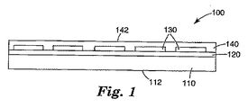
図1は本発明のタッチスクリーン構成100を示し、それに含まれるのは、基板110、その基板110を覆うコーティング120、そのコーティング120の上に配置されたパターン化透明導体層130、およびその透明導体パターン130の上に配置された充填材料140であって、その充填材料140は、その透明導電材料によって覆われていない領域においてコーティング120に接触している。タッチスクリーン構成100は、使用者によって作動されるタッチ入力装置に使用することができ、その場合透明導体パターン130がタッチセンシング要素の役目を果たす。
FIG. 1 shows a
基板の表面112または充填材料の表面142を、そのタッチ表面とすることができる。別な方法として、場合によっては使用者と基板110または充填材料142との間に1層または複数の追加の層を配して、タッチ表面とすることも可能である。たとえば、除去可能で張り替え可能なオーバーレイ層を設けて、タッチ表面に傷が付いたりその他損傷があったりした場合には、そのタッチスクリーンのタッチ表面を「更新(refresh)」することも可能である。別な例としては、特に基板110がプラスチック基板であるような場合には、基板110の表面112の上にハードコートを配して、タッチ表面とすることもできる。また別な例としては、基板110または充填材料140に、望ましい耐久性あるいはその他の性質を有するガラスまたはその他の材料のシートを積層するかまたはその他の方法で接着させることも可能であるが、その際にはそれらの間に他の構造用の層または機能性層が存在していても、存在していなくてもよい。
タッチスクリーン構成100は、可視光線を透過させて、ディスプレイ、グラフィックス、その他の情報または表示をそのタッチスクリーンを通して見ることができるようになっているのが好ましい。したがって、図1に表示された各構成要素は、可視光線透過性であるのが好ましい。
基板110は、ガラスまたはプラスチックを含めて、いかなる材料であってもよい。プラスチックの例としては、PET、ポリカーボネート、ポリアクリレート、実質的に透明なポリイミド、実質的に透明なポリウレタンなどを挙げることができる。基板110は剛性であっても可撓性であってもよい。場合によっては基板110には、たとえば表面112の上に追加のコーティングが含まれていてもよく、そのようなものとしては、ハードコート、反射防止コーティング、偏光子、リターダー、波長板、散光板、防眩コーティング、調光フィルムなどが挙げられる。
The
コーティング120は、所望の厚みにコーティングして適切に加工処理したときに、望ましくは可視光線を透過するような、各種適切な材料とすることができる。コーティング120は、基板110の屈折率より低く、また透明導電材料130の屈折率よりも低い屈折率を有している。たとえば、基板110としてPETを使用し、透明導体130としてITOを使用する場合のコーティング120のための材料の例としては、ケイ素酸化物たとえばSiO2を挙げることができる。コーティング120は実質的に基板110を覆っていて、スパッタ堆積、化学蒸着などの適切な手段により、設けることができる。いかなる理論にも拘束されることを望まないが、コーティング120では、透明導体パターン130によって覆われた領域において、タッチスクリーン100を通過する可視光線の反射を抑制できるだけの厚みを選択するのが好ましい。
The
透明導体パターン130としては、各種適切な透明導電材料、たとえば透明導電性酸化物または透明導電性ポリマーなどを挙げることができる。透明導電性酸化物の例としては、インジウムスズ酸化物(ITO)、スズアンチモン酸化物(TAO)、スズ酸化物(TO)などが挙げられる。導電性ポリマーの例としては、ポリピロール、ポリアニリン、ポリアセチレン、ポリチオフェン、ポリフェニレンビニレン、ポリフェニレンスルフィド、ポリp−フェニレン、ポリヘテロシクリルビニレン、および、欧州特許出願公開第1−172−831−A2号明細書(この特許の全体を参照により本明細書に援用する)に開示されている材料などが挙げられる。透明導体パターン130は、各種好適な手段を用いてパターン化することができるが、たとえば、マスクを介して透明導電材料を堆積させて透明導電材料の膜を形成させ、次いで、その材料のいくつかの部分をエッチングまたはその他適切な除去方法を用いて除去する。透明導電材料をパターン化することによって、コーティング120のある部分がパターン130によって覆われ、コーティング120のその他の部分がパターン130によって覆われずに残る。
Examples of the
構成の例を挙げてみると、基板110が、PET(屈折率約1.67)のフィルム、コーティング120が厚み約15〜70nmの範囲、好ましくは25nmのケイ素酸化物たとえばSiO2(屈折率約1.45)のコーティング、そして透明導体130が、厚み約20〜35nmのITO(屈折率約2.0)である。
As an example of the configuration, the
充填材料140は、透明導体パターン130の上に塗布するかまたは他の方法で配され、それによって、それがパターン130を覆い、かつパターン130の部分の間のギャップを実質的に充填し、パターン130によって覆われていない領域でコーティング120と接触しているようにすることが可能な、適切な材料であればいかなるものであってもよい。充填材料140は、コーティング120のために使用している材料と同じものであってもよい。いくつかの実施態様においては、充填材料140は、光学的に透明な接着剤、たとえば光学グレードのアクリル系感圧接着剤のような接着材料であってよい。基板110がPET、コーティング120がケイ素酸化物、透明導体130がITOであるような構成においては、充填材料140の屈折率が約1.4〜1.8であるのが好ましい。たとえば、そのような構成における好適な充填材料としては、アクリル系感圧接着剤またはケイ素酸化物を挙げることができる。
構成100は、ディスプレイスクリーン、その他の基板(たとえばガラスまたはその他の剛性または可撓性の板)、またはその他適切な対象物の前面のような対象物に接着させるように、配置することができる。これは、基板110の表面112の上、充填材料140の表面142の上、表面112または表面142の上に堆積させたその他の(単一または複数の)層の上、に接着剤を配するか、または充填材料140としての接着剤を使用して接着性充填剤を直接に接着させることによって、実施することができる。そのような場合においては、剥離ライナーを接着剤層の上に設けて、その剥離ライナーを剥がすまでの貯蔵および取扱いを容易にして、その構成物を所望の表面に適切に接着させることができる。
The
図2は、図1に示したものと同様ではあるが、第二の基板をさらに含むタッチスクリーン構成200を示す。タッチスクリーン構成200に含まれるのは、第一の基板210、その第一の基板210を覆うコーティング220、コーティング220の上に配置された透明導体パターン230、透明導体パターン230を覆い、パターン230によって覆われていない領域にあるコーティング220と接触する充填材料240、およびその充填材料240の上に配置された第二の基板250である。基板250は、充填材料240と基板250との間に配置された接着剤を使用することによって、構成200に接着させることができる。別な方法として、充填材料240それ自体を接着材料として、基板250を構成200に接着させるのに使用することも可能である。充填剤層240が接着剤であるようないくつかの実施態様においては、透明導体パターン230およびコーティング220の上に配置することが可能な各種適切な接着剤を使用することによって、その接着剤を透明導体パターン230およびコーティング220の覆われていない部分に接触させることができる。接着剤の例としては、感圧接着剤および/またはアクリル系の接着剤を挙げることができ、それらは光学的に透明であるのが好ましい。基板250はガラスおよびプラスチックを含めた各種適切な材料であればよく、それらは剛性であっても、可撓性であってもよい。
FIG. 2 shows a
構成100の透明導体パターン130および構成200の透明導体パターン230は、タッチスクリーンのためのセンシング要素を形成することができる。導電性のタッチ対象物、たとえば使用者の指が充分に近いところまでくると、その導電性タッチ対象物がそれら透明導体パターンを形成しているセンシング要素の一つまたは複数と容量結合されることが可能となる。多くの場合、その透明導体パターンには、独立して扱うことが可能な透明導電性の線、ストライプ、パッド、トレースなどが含まれる。制御電子機器がそれらのそれぞれを駆動していて、タッチ対象物との間での容量結合によって、検出可能な信号が得られる。それらの信号の強度から、透明導体パターンのどの部分が容量結合されたかが検出でき、それによってそのタッチの位置を識別することが可能である。
The
図3には、タッチスクリーン300の1例を示すが、これには、基板310の上に配置された複数の平行な透明導電性バー330が含まれる。それぞれのバー330は、第一の末端370Aと第二の末端370Bに結合され、それぞれが導線380Aおよび380Bに接続されることができる。それらの導線は、それぞれのバーが独立して認識されるように構成されている。導線は、タッチスクリーン300の端部でまとめてグルーピング360に束ねて、タッチスクリーンと制御電子機器(図示せず)とを電気的に結合するための電子テイル(図示せず)にそれを接続することができる。そのようなタッチスクリーンの例は、米国特許第5,650,597号明細書、米国特許出願公開第2003/0103043号明細書、米国特許出願第10/176564号明細書、同第10/324728号明細書、および同第10/201400号明細書に開示されている(それら明細書のそれぞれを、参照により本明細書に援用するものとする)。タッチされた位置は、バーが最も大きな信号を示す(位置精度をさらに上げるには補間法を使用)バーがどれであるかからのy方向と、バーのそれぞれの末端を流れる電流量を比較することによるx方向と、から求めることができる。このタイプのタッチスクリーンは、3M・タッチ・システムズ・インコーポレーテッド(3M Touch Systems,Inc.)から商品名ニア・フィールド・イメージング(Near Field Imaging)として市販されている。
FIG. 3 shows an example of a
図4には、本発明のまた別なタッチスクリーン構成400が示され、それに含まれるのは、第一の基板410、その基板410を実質的に覆う第一のコーティング420、および第一のコーティング420の上に配置された平行な透明導電性トレース430の第一の組である。タッチスクリーン400にはさらに、第二のコーティング425によって実質的に覆われた第二の基板415と、第二のコーティング425の上に配置され、透明導電性トレース430の第一の組とは直交して配列された透明導電性トレース435の第二の組とが含まれる。充填材料440は、透明導電性トレース430の第一の組と、透明導電性トレース435の第二の組との間に配置され、透明導電性トレースによって覆われていない領域で、第一のコーティング420および第二のコーティング425と接触している。充填材料440は、第一の基板410、第一のコーティング420および第一のパターン430を、第二の基板415、第二のコーティング425および第二パターン435と接着させるための接着剤であるのが好ましい。第一のコーティング420は、第一の基板410および透明導電性トレース430の第一の組の屈折率よりは低い屈折率を有する。同様にして、第二のコーティング425は、第一の基板415および透明導電性トレース435の第一の組の屈折率よりは低い屈折率を有する。
FIG. 4 illustrates another
操作の際には、導電性タッチ対象物が、第一の基板410または第二の基板415のいずれかを通して、透明導電性トレース430の第一の組の少なくとも一つ、および透明導電性トレースの第二の組の少なくとも一つと容量結合することによって、そのタッチ入力のx座標とy座標を与えることができる。このタイプのタッチスクリーンは、マトリックスタイプのタッチスクリーンと呼ぶこともできる。マトリックスタイプのタッチスクリーンの例は、米国特許第6,188,391号明細書;同第5,844,506号明細書;同第5,386,219号明細書、さらには国際公開第01/27868号パンフレット、同第02/100074号パンフレット、同第01/52416号パンフレットに開示されている。
In operation, the conductive touch object passes through either the
図5に、本発明によるマトリックスタイプのタッチスクリーンの別な例を示す。タッチスクリーン構成500に含まれるのは、一つの表面を実質的に覆う第一のコーティング520と、反対側の表面を実質的に覆う第二のコーティング525とを有する基板510である。透明導電性トレース530の第一の組は、第一のコーティング520の上に配置され、透明導電性トレース535の第二の組は、第二のコーティング525の上に、透明導電性トレースの第一の組とは直交する方向で、配置されている。この方法では、同一の基板510が、背中合わせの両方の表面の上に、コーティングと透明導体パターンを有している。充填材料540(接着剤であるのが好ましい)が、透明導電性トレース530の上に配置されて、充填材料が透明導電性トレース530を覆い、かつ透明導電性トレース530によって覆われていない領域においてはコーティング520と接触するようになっている。充填剤層540の上には、任意の上側基板550を配置することができ、そして独立した接着剤層を用いるかまたは充填材料そのものが接着剤である場合には充填剤層540を介して、構成500と接着させることができる。任意の接着剤またはその他の充填剤層545を、透明導電性トレース535の上に配置することができ、任意の下側基板555を、(もし存在すれば)任意の充填剤層545の上に配置することができる。
FIG. 5 shows another example of a matrix type touch screen according to the present invention. Included in the
図6に、本発明による別なタッチスクリーンを示す。タッチスクリーン600には、接着剤層680を介して支持基板690に接着されたタッチスクリーン構成670が含まれる。タッチスクリーン構成670に含まれるのは、第一のコーティング625により塗布された第一の基板615、その第一のコーティング625の上に配置された第一の透明導体パターン635、および第一の透明導体パターン635の上に配置され、パターン635の部分の間のギャップを充填し、コーティング625と接触している、第一の充填材料645である。タッチスクリーン構成670にさらに含まれているのは、第二のコーティング620により塗布された第二の基板610、その第二のコーティング620の上に配置された第二の透明導体パターン630、および第二の透明導体パターン630の上に配置され、パターン630の部分の間のギャップを充填し、コーティング620と接触している、第二の充填材料640である。構成670にはさらに、ハードコート層660を有する上側基板650が含まれていて、その構成のためのタッチ表面を与えるようになっている。充填材料640と645が接着材料であって、その構成の隣接する要素を互いに接合させるのが好ましい。別な方法として、独立した接着剤層(図示せず)を使用することもできる。
FIG. 6 shows another touch screen according to the present invention. The
支持基板690は、剛性、可撓性を含めて適切な基板なら何であってもよく、たとえばガラスやプラスチックであってよい。実施態様の例を挙げれば、支持基板690が剛性のガラス基板であり、基板610、615、および650が可撓性のプラスチック基板である。この方法では、ロール・ツゥ・ロール法またはその他適切な加工方法を用いて、可撓性の基板の610、615、および650のそれぞれの上に構成670のサブ構成を作ることが可能である。次いでそれらのサブ構成のそれぞれを積層法またはその他の方法を用いて互いに接着させて、構成670を形成させ、次いでそれを支持基板690に接着させることができる。
The
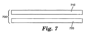
図7は、タッチスクリーンシステム700を模式的に示したもので、それにはディスプレイ要素720のすぐ側に配置された本発明によるタッチスクリーン710が含まれていて、タッチスクリーン710を通してディスプレイ要素720を見ることができるようになっている。ディスプレイ要素720の上に表示される情報と対話するための入力機器として、タッチスクリーン710を使用することができる。ディスプレイ要素720は、テキストやグラフィックスのような情報を次々と表示することが可能な電子ディスプレイであればよい。ディスプレイ要素720にはさらに、印刷されたグラフィックス、テキストあるいはその他の表示のような静的な情報が含まれていてもよい。ディスプレイ要素720は、たとえば、ディスプレイスクリーンの上におけるアイコンの形式のような、電子的ディスプレイを静的グラフィックスと組み合わせたものであってもよく、それらは、ディスプレイスクリーンの上に直接印刷されるかまたは他の方法で配置されていてもよいし、あるいは、タッチスクリーン710を通して見ることが可能な別なシートの上に設けられていてもよい。グラフィックス、符号、その他の表示はまた、タッチスクリーン710の前面に設けられていてもよい。
FIG. 7 schematically illustrates a
ニア・フィールド・イメージング(Near Field Imaging)タッチセンサ構成は、以下の手順によって作製した。 A Near Field Imaging touch sensor configuration was made by the following procedure.
PETの7ミル(約0.2mm)のシートの上にSiO2をスパッタコーティングして、そのPET基板を実質的に覆う250オングストロームのSiO2のコーティングを形成させた。使用したPET基板は、印刷処理を用いて一つの表面の上にプライマー処理をした標準的なPETフィルムであった。そのSiO2は印刷処理をしていない側の上にコーティングした。そのSiO2コーティングの屈折率は約1.46であった。 SiO 2 was sputter coated onto a 7 mil (about 0.2 mm) sheet of PET to form a 250 Å SiO 2 coating substantially covering the PET substrate. The PET substrate used was a standard PET film with a primer treatment on one surface using a printing process. The SiO 2 was coated on the non-printed side. The refractive index of the SiO 2 coating was about 1.46.
除去可能で、水溶性のパターニングインキを、SiO2の表面の、透明導体パターンの指定のない、たとえばパターンの指定領域の中間領域、および境界領域にスクリーン印刷した。 A removable, water-soluble patterning ink was screen printed on the surface of SiO 2 without a transparent conductor pattern designation, for example, in the middle area of the designated area of the pattern, and in the boundary area.
ITOをそのSiO2とスクリーン印刷した水溶性インキの両方の上にスパッタコーティングして、450オーム/スクエアの抵抗率を与えるのに充分な厚みとした。ITOは、金属ターゲットまたはセラミックターゲットを使用して、広い範囲の温度および加工条件下で、適切にスパッタコーティングすることができる。 ITO was sputter coated onto both the SiO 2 and screen-printed water-soluble ink to a thickness sufficient to give a resistivity of 450 ohm / square. ITO can be appropriately sputter coated using a metal or ceramic target under a wide range of temperatures and processing conditions.
そのパターニングインキを、水を用いて除去し、そのサンプルを乾燥させると、センシング電極の透明導体パターンとしての、ITOバーのパターンが残った。 When the patterning ink was removed using water and the sample was dried, an ITO bar pattern as a transparent conductor pattern of the sensing electrode remained.
導電性銀インキをそのITOとSiO2との上にスクリーン印刷し、乾燥させて、厚み約0.3〜0.6ミル(約8〜15ミクロン)として、ITOバーのそれぞれに接続された導電性トレースを形成させた。 The conductive silver ink screen-printed on its ITO and SiO 2, and dried to a thickness of about 0.3-0.6 mils (about 8-15 microns), the conductive connected to the respective ITO bars Sex traces were formed.
溶媒系のエポキシ絶縁インキをその導電性銀インキの上にスクリーン印刷して加熱硬化させるが、エポキシの中に電気接続のためのバイアを残して、電気テイルとした。この印刷工程を繰り返して、2層を形成させた。 A solvent-based epoxy insulating ink was screen printed onto the conductive silver ink and cured by heating, leaving an electrical connection via in the epoxy to form an electrical tail. This printing process was repeated to form two layers.
導電性銀インキトレースをその印刷絶縁層の上にスクリーン印刷し、乾燥させて厚み0.3〜0.6ミル(約8〜15ミクロン)として、バイアを通過する接続を作った。 A conductive silver ink trace was screen printed onto the printed insulating layer and dried to a thickness of 0.3-0.6 mil (about 8-15 microns) to make a connection through the via.
テイルの末端の上の銀インキの上に、導電性カーボンインキをスクリーン印刷し、乾燥させて厚み0.3〜0.6ミル(約8〜15ミクロン)として、腐蝕および摩耗からトレースを保護した。 On top of the silver ink on the tail ends, conductive carbon ink was screen printed and dried to a thickness of 0.3-0.6 mils (about 8-15 microns) to protect the traces from corrosion and abrasion. .
1.42ミル(約0.036mm)のPETフィルムを、光学用アクリル系感圧接着剤でコーティングして、0.5ミル(約13ミクロン)の厚みの層とし、そのサンプルに、接着剤側を下にし、電気テイルを露出させた状態に残して、ロール・ツゥ・ロール法により積層した。 A 1.42 mil (about 0.036 mm) PET film is coated with an optical acrylic pressure sensitive adhesive to form a 0.5 mil (about 13 micron) thick layer on the adhesive side. Was laminated with the roll-to-roll method leaving the electric tail exposed.
第一のPETフィルムの印刷処理した側をITOでスパッタコーティングして、約150オーム/スクエアの抵抗率が得られるのに充分な厚みとした。このITOが、そのタッチセンサ装置のシールド層を形成している。 The printed side of the first PET film was sputter coated with ITO to a thickness sufficient to obtain a resistivity of about 150 ohms / square. This ITO forms the shield layer of the touch sensor device.
ITOシールド層の周辺と電気テイルのまわりに、導電性銀インキをスクリーン印刷し、乾燥させて、厚み約0.3〜0.6ミル(約8〜15ミクロンmm)として、シールド層のための電気接点とした。 Conductive silver ink is screen printed around the ITO shield layer and around the electrical tail and dried to a thickness of about 0.3-0.6 mil (about 8-15 microns mm) for the shield layer Electrical contacts were used.
シールド層の上の導電性銀インキの上に、溶媒系のエポキシ絶縁インキをスクリーン印刷して、加熱硬化させた。 A solvent-based epoxy insulating ink was screen-printed on the conductive silver ink on the shield layer and cured by heating.
第二の積層PETフィルムの周辺のまわりに導電性銀インキをスクリーン印刷し、上側ガード層を形成させた。その銀インキを乾燥させると、厚みが0.3〜0.6ミル(約8〜15ミクロンmm)となった。 A conductive silver ink was screen-printed around the periphery of the second laminated PET film to form an upper guard layer. When the silver ink was dried, the thickness was 0.3-0.6 mil (about 8-15 microns mm).
溶媒系のエポキシ絶縁インキを上側ガード層の上にスクリーン印刷して、加熱硬化させた。 A solvent-based epoxy insulating ink was screen printed on the upper guard layer and cured by heating.
厚み7ミル(約0.18mm)のアクリル系ハードコーティングしたPETフィルムを、アクリル系光学グレード感圧接着剤(0.8ミル(0.02mm)接着剤/0.92ミル(0.023mm)PET/0.8ミル(0.02mm)接着剤)を含む多層構成に積層させ、次いでその構成の上側ガード層の上に積層させた。 A 7 mil (about 0.18 mm) thick acrylic hard-coated PET film is converted to an acrylic optical grade pressure sensitive adhesive (0.8 mil (0.02 mm) adhesive / 0.92 mil (0.023 mm) PET). /0.8 mil (0.02 mm) adhesive) and then over the upper guard layer of that configuration.
剥離ライナーを付けた、アクリル系光学用接着剤/PET/アクリル系光学用接着剤の構成(0.8ミル(0.02mm)接着剤/0.92ミル(0.023mm)PET/0.8ミル(0.02mm)接着剤)をバックシールドに積層させた。 Composition of acrylic optical adhesive / PET / acrylic optical adhesive with release liner (0.8 mil (0.02 mm) adhesive / 0.92 mil (0.023 mm) PET / 0.8 A mill (0.02 mm adhesive) was laminated to the back shield.
その構成の上側表面を、ポリエチレン/接着剤マスク材料を用いてマスキングし、その構成を切断してシートとし、次いでそれをダイカットして部材とした。 The upper surface of the configuration was masked with a polyethylene / adhesive mask material, the configuration was cut into a sheet, and then it was die cut into a member.
そのダイカットした部材を、ガラスバッキングパネルに積層させた。 The die-cut member was laminated on a glass backing panel.
得られた部材は、反射光、透過光のいずれによっても見ることが極めて困難なITOバーを有していて、そのITOバーは、ITOバーに容量結合されている導電性タッチ手段の位置を検知するための制御電子機器に接続できるように、配列されている。 The resulting member has an ITO bar that is very difficult to see by either reflected or transmitted light, and the ITO bar detects the position of the conductive touch means that is capacitively coupled to the ITO bar. Is arranged so that it can be connected to the control electronics.
光学的なモデルを使用して、本発明の構成と、それとは別な、同様の構成ではあるが基板と透明導体の間に低屈折率コーティングを含まないものとの可視光線の内部透過率を比較した。それぞれの構成とそれに対応する比較例の構成を、透明導体層を含まない同様の対照の構成とさらに比較した。それぞれの構成と対応する対照の構成との間の透過率の違いは、問題としている構成の中での、透明導体パターンによって覆われた領域と、透明導体パターンによって覆われていない領域とを比較した、識別性の相対的レベルを表している。以下の構成を評価したが、層はそれぞれの構成における順で示している:
構成1:
屈折率1.67の層(PET基板をシミュレート)
厚み30nmの屈折率1.46の層(ケイ素酸化物をシミュレート)
厚み20nmの屈折率2.0の層(ITOをシミュレート)
厚み30nmの屈折率1.46の層(ケイ素酸化物をシミュレート)
屈折率1.5の層(光学用接着剤をシミュレート)
比較例構成C1(構成1と同様であるが、基板とITOの間にコーティングなし):
屈折率1.67の層(PET基板をシミュレート)
厚み20nmの屈折率2.0の層(ITOをシミュレート)
厚み30nmの屈折率1.46の層(ケイ素酸化物をシミュレート)
屈折率1.5の層(光学用接着剤をシミュレート)
対照例構成X1:
屈折率1.67の層(PET基板をシミュレート)
厚み30nmの屈折率1.46の層(ケイ素酸化物をシミュレート)
屈折率1.5の層(光学用接着剤をシミュレート)
構成2:
屈折率1.67の層(PET基板をシミュレート)
厚み30nmの屈折率1.46の層(ケイ素酸化物をシミュレート)
厚み20nmの屈折率2.0の層(ITOをシミュレート)
屈折率1.5の層(光学用接着剤をシミュレート)
比較例構成C2(構成2と同様であるが、基板とITOの間にコーティングなし):
屈折率1.67の層(PET基板をシミュレート)
厚み20nmの屈折率2.0の層(ITOをシミュレート)
屈折率1.5の層(光学用接着剤をシミュレート)
対照例構成X2:
屈折率1.67の層(PET基板をシミュレート)
屈折率1.5の層(光学用接着剤をシミュレート)
Using an optical model, the internal transmission of visible light between the configuration of the present invention and a separate but similar configuration that does not include a low refractive index coating between the substrate and the transparent conductor. Compared. Each configuration and the corresponding configuration of the comparative example were further compared to a similar control configuration that did not include a transparent conductor layer. The difference in transmittance between each configuration and the corresponding control configuration is the comparison between the area covered by the transparent conductor pattern and the area not covered by the transparent conductor pattern in the configuration in question. Represents the relative level of discrimination. The following configurations were evaluated, but the layers are shown in order in each configuration:
Configuration 1:
Layer with a refractive index of 1.67 (simulating a PET substrate)
30 nm thick layer with refractive index of 1.46 (simulating silicon oxide)
20 nm thick refractive index 2.0 layer (simulating ITO)
30 nm thick layer with refractive index of 1.46 (simulating silicon oxide)
Refractive index 1.5 layer (simulating optical adhesive)
Comparative configuration C1 (similar to configuration 1, but without coating between substrate and ITO):
Layer with a refractive index of 1.67 (simulating a PET substrate)
20 nm thick refractive index 2.0 layer (simulating ITO)
30 nm thick layer with refractive index of 1.46 (simulating silicon oxide)
Refractive index 1.5 layer (simulating optical adhesive)
Control configuration X1:
Layer with a refractive index of 1.67 (simulating a PET substrate)
30 nm thick layer with refractive index of 1.46 (simulating silicon oxide)
Refractive index 1.5 layer (simulating optical adhesive)
Configuration 2:
Layer with a refractive index of 1.67 (simulating a PET substrate)
30 nm thick layer with refractive index of 1.46 (simulating silicon oxide)
20 nm thick refractive index 2.0 layer (simulating ITO)
Refractive index 1.5 layer (simulating optical adhesive)
Comparative Example Configuration C2 (similar to Configuration 2, but without coating between substrate and ITO):
Layer with a refractive index of 1.67 (simulating a PET substrate)
20 nm thick refractive index 2.0 layer (simulating ITO)
Refractive index 1.5 layer (simulating optical adhesive)
Control configuration X2:
Layer with a refractive index of 1.67 (simulating a PET substrate)
Refractive index 1.5 layer (simulating optical adhesive)
これらの構成のそれぞれの可視光線(波長400nm〜700nm)の内部透過率を、SCI・フィルム・ウィザード(SCI Film Wizard)光学モデリングソフトウェアを用いて、モデル化した。可視スペクトル中の3種の波長についての結果を表1に示す。Δは、同定された構成と対応する対照構成との間の透過率の差を表している。
The internal transmittance of visible light (

このモデリングの結果から、本発明の構成は、可視スペクトルの全域にわたって透明導体パターンによって覆われた領域において、高い透過率を示すことが判る。このモデリングの結果からはさらに、基板と透明導体パターンの間に低屈折率コーティングを含まないがその他は同一の比較例の構成の場合よりも、本発明の構成の方が、透明導体によって覆われた領域と透明導体によって覆われていない領域との間での透過率の差が低いことも判る。覆われた領域と覆われていない領域との間の透過率の差がそのように低くなったことで、視覚的に識別しにくい透明導体パターンが得られた。 From the modeling results, it can be seen that the configuration of the present invention exhibits high transmittance in the region covered by the transparent conductor pattern over the entire visible spectrum. From this modeling result, the configuration of the present invention is further covered by the transparent conductor than the configuration of the same comparative example that does not include a low refractive index coating between the substrate and the transparent conductor pattern. It can also be seen that the difference in transmittance between the exposed area and the area not covered by the transparent conductor is low. The difference in transmittance between the covered and uncovered areas was so low that a transparent conductor pattern that was difficult to visually identify was obtained.
構成1および2の場合のΔを、可撓性の基板上のそのようなタッチスクリーンの典型的な公知の構成を最も代表している比較例構成C2のΔと比較すると、さらに判ることがある。対照例の構成X1とX2はいずれも光学的性能は同一であるので、それらのΔを直接比較することができる。そのような比較から、構成1と構成2のいずれにおいても、比較例構成C2と比較して、全可視スペクトル領域において、ITOで覆われた領域における透過率が改善されており、またITOの上下にケイ素酸化物層を含む構成1の方が、ITOの下だけにケイ素酸化物層を含む構成2よりも、可視スペクトル領域においてわずかに改良された透過率を示していることが判る。 Further comparison of Δ for configurations 1 and 2 with Δ of comparative example configuration C2, which is most representative of a typical known configuration of such a touch screen on a flexible substrate, may be further understood. . Since the optical configurations of the control examples X1 and X2 are the same, their Δ can be directly compared. From such a comparison, in both the configuration 1 and the configuration 2, the transmittance in the region covered with ITO is improved in the entire visible spectrum region as compared with the comparative example configuration C2. It can be seen that the configuration 1 including the silicon oxide layer in the first example shows slightly improved transmittance in the visible spectrum region than the configuration 2 including the silicon oxide layer only under the ITO.
本発明は、上述の具体的な例だけに限定されるとは考えてはならず、むしろ、添付の特許請求項に明確に言及されている本発明のすべての態様を包含していると理解すべきである。各種の修正例、等価のプロセス、さらには本発明を適用することが可能な各種の構造は、本明細書を精読することにより、本発明が対象としている当業者には、容易に明らかとなるであろう。 The present invention should not be considered limited to the specific examples described above but rather encompasses all aspects of the invention explicitly referred to in the appended claims. Should. Various modifications, equivalent processes, and various structures to which the present invention can be applied will be readily apparent to those skilled in the art to which the present invention is directed after reading this specification. Will.
Claims (37)
基板;
前記基板を実質的に覆うコーティング;
前記コーティングの上に配置された透明導体パターンであって、覆われていないコーティングの領域を残している、パターン;および
透明導体パターンと、前記透明導体パターンによって覆われていないコーティングの領域との両方を覆い、接触している充填材料を含み;
ここで前記コーティングが、前記基板の屈折率より低く、かつ前記透明導体パターンの屈折率より低い屈折率を有する、タッチスクリーン。 Touch screen:
substrate;
A coating that substantially covers the substrate;
A transparent conductor pattern disposed over the coating, leaving a region of the coating not covered; and both the transparent conductor pattern and a region of the coating not covered by the transparent conductor pattern Including filling material that is in contact with and in contact with;
Wherein the coating has a refractive index lower than the refractive index of the substrate and lower than the refractive index of the transparent conductor pattern.
PET基板;
前記PET基板を覆うケイ素酸化物層;
前記ケイ素酸化物層の上に配置された平行なITOバーのアレイ;および
前記ITOバーの上に配置され、それらを覆う光学的に透明な感圧接着剤を含み、前記光学的に透明な感圧接着剤が、両端を含めて1.4〜1.8の範囲の屈折率を有する、タッチスクリーン構成。 Touch screen configuration:
PET substrate;
A silicon oxide layer covering the PET substrate;
An array of parallel ITO bars disposed on the silicon oxide layer; and an optically transparent pressure sensitive adhesive disposed on and covering the ITO bars; A touch screen configuration in which the pressure adhesive has a refractive index in the range of 1.4 to 1.8 including both ends.
前記タッチスクリーン構成が:
基板の上にパターン化された透明導体;
前記基板を実質的に覆い、前記透明導体と前記基板の間に配置された第一の層であって、前記第一の層が、前記透明導体によって覆われた領域におけるタッチスクリーンを通過する可視光線の透過率を向上させるように配置される、第一の層;および
前記透明導体によって覆われた領域において前記透明導体と接触し、前記透明導体で覆われていない領域において前記第一の層と接触するように配置された第二の層であって、前記第二の層が、前記第一の層と前記第二の層との間の接触界面において可視光線の反射を実質的に抑制するように構成される、第二の層を含む、タッチスクリーン。 A touch screen including a touch screen configuration:
The touch screen configuration is:
Transparent conductor patterned on the substrate;
A first layer substantially covering the substrate and disposed between the transparent conductor and the substrate, the first layer being visible through a touch screen in an area covered by the transparent conductor; A first layer arranged to improve light transmittance; and the first layer in a region that is in contact with the transparent conductor in a region covered by the transparent conductor and is not covered by the transparent conductor A second layer disposed in contact with the second layer, wherein the second layer substantially suppresses reflection of visible light at a contact interface between the first layer and the second layer. A touch screen including a second layer configured to be.
基板と前記パターン化透明導体との間のアンダーコート材料をコーティングする工程であって、それにより、前記アンダーコート材料が実質的に前記基板を覆い、前記アンダーコート材料が、前記基板および前記パターン化透明導体の屈折率より低い屈折率を有し、ここで前記パターン化透明導体が、露出されたアンダーコート材料の領域を残すようにする工程;および
前記パターン化透明導体と、前記アンダーコート材料の露出された領域との上に充填材料を配置する工程を含み、前記充填材料が、前記パターン化透明導体によって覆われた領域における可視光線の界面反射を抑制するように選択された、屈折率と厚みとを有する、方法。 A method for reducing the visibility of a patterned transparent conductor on a touch screen, comprising:
Coating an undercoat material between a substrate and the patterned transparent conductor, whereby the undercoat material substantially covers the substrate, the undercoat material comprising the substrate and the patterned Having a refractive index lower than that of the transparent conductor, wherein the patterned transparent conductor leaves a region of exposed undercoat material; and the patterned transparent conductor and the undercoat material A refractive index selected to suppress interfacial reflection of visible light in an area covered by the patterned transparent conductor; and disposing a filler material over the exposed area; Having a thickness.
Applications Claiming Priority (2)
| Application Number | Priority Date | Filing Date | Title |
|---|---|---|---|
| US10/686,141 US8068186B2 (en) | 2003-10-15 | 2003-10-15 | Patterned conductor touch screen having improved optics |
| PCT/US2004/029604 WO2005040901A2 (en) | 2003-10-15 | 2004-09-13 | Patterned conductor touch screen having improved optics |
Publications (2)
| Publication Number | Publication Date |
|---|---|
| JP2007508639A true JP2007508639A (en) | 2007-04-05 |
| JP2007508639A5 JP2007508639A5 (en) | 2007-11-01 |
Family
ID=34520716
Family Applications (1)
| Application Number | Title | Priority Date | Filing Date |
|---|---|---|---|
| JP2006535494A Pending JP2007508639A (en) | 2003-10-15 | 2004-09-13 | Patterned conductor touch screen with improved optical properties |
Country Status (9)
| Country | Link |
|---|---|
| US (1) | US8068186B2 (en) |
| EP (1) | EP1678599B1 (en) |
| JP (1) | JP2007508639A (en) |
| CN (1) | CN1867882A (en) |
| AT (1) | ATE473481T1 (en) |
| AU (1) | AU2004284746A1 (en) |
| DE (1) | DE602004028035D1 (en) |
| TW (1) | TW200527304A (en) |
| WO (1) | WO2005040901A2 (en) |
Cited By (34)
| Publication number | Priority date | Publication date | Assignee | Title |
|---|---|---|---|---|
| JP2008098169A (en) * | 2005-05-26 | 2008-04-24 | Gunze Ltd | Transparent planar body and transparent touch switch |
| JP2008217784A (en) * | 2007-03-07 | 2008-09-18 | Elan Microelectronics Corp | Touch panel |
| JP2009026152A (en) * | 2007-07-20 | 2009-02-05 | Sony Corp | Input device and electronic equipment |
| JP2009053893A (en) * | 2007-08-27 | 2009-03-12 | Epson Imaging Devices Corp | Electrostatic capacitance type input device |
| JP2009098834A (en) * | 2007-10-16 | 2009-05-07 | Epson Imaging Devices Corp | Capacitance type input device, display device with input function and electronic equipment |
| JP2009211680A (en) * | 2008-02-08 | 2009-09-17 | Fujitsu Component Ltd | Panel-type input device, method of manufacturing panel-type input device, and electronic device having panel-type input device |
| JP2009259203A (en) * | 2008-03-25 | 2009-11-05 | Epson Imaging Devices Corp | Capacitive input device, display device with input function, and electronic apparatus |
| JP2010146785A (en) * | 2008-12-17 | 2010-07-01 | Hitachi Displays Ltd | Capacitance type touch panel and screen-input type display equipped with the same |
| JP2010182528A (en) * | 2009-02-05 | 2010-08-19 | Toppan Printing Co Ltd | Transparent conductive film |
| JP2010231186A (en) * | 2009-03-04 | 2010-10-14 | Sony Corp | Display device |
| JP2010257492A (en) * | 2008-03-25 | 2010-11-11 | Sony Corp | Capacitive input device, display device with input function, and electronic apparatus |
| JP2011060617A (en) * | 2009-09-11 | 2011-03-24 | Toppan Printing Co Ltd | Transparent conductive laminate, method of manufacturing the same, and capacitance touch panel |
| JP2011123860A (en) * | 2009-12-09 | 2011-06-23 | J Touch Corp | Capacitive touch control device structure |
| JP2011170508A (en) * | 2010-02-17 | 2011-09-01 | Alps Electric Co Ltd | Input device |
| JP2011221977A (en) * | 2010-04-09 | 2011-11-04 | J Touch Corp | Non-contact type touch panel |
| JP2012027889A (en) * | 2010-07-27 | 2012-02-09 | Samsung Electro-Mechanics Co Ltd | Capacitance touch screen |
| JP2012118936A (en) * | 2010-12-03 | 2012-06-21 | Dainippon Printing Co Ltd | Touch panel sensor with transparent sheet |
| JP2012138028A (en) * | 2010-12-27 | 2012-07-19 | Dainippon Printing Co Ltd | Manufacturing method of touch panel member and touch panel member |
| JP2012146211A (en) * | 2011-01-13 | 2012-08-02 | Dainippon Printing Co Ltd | Touch panel sensor with transparent sheet |
| JP2012160203A (en) * | 2012-04-24 | 2012-08-23 | Japan Display East Co Ltd | Touch panel and display using the same |
| JP2012203701A (en) * | 2011-03-25 | 2012-10-22 | Dainippon Printing Co Ltd | Touch panel member, substrate with transparent electrode layer, substrate laminate type touch panel member, and coordinate detection device using touch panel member or substrate laminate type touch panel member |
| JP2012247813A (en) * | 2011-03-29 | 2012-12-13 | Alps Electric Co Ltd | Input device, and manufacturing method of the same |
| EP2579277A1 (en) | 2011-10-06 | 2013-04-10 | Nitto Denko Corporation | Transparent conductive film |
| JP2013114344A (en) * | 2011-11-25 | 2013-06-10 | Nitto Denko Corp | Touch panel sensor |
| JP2013532868A (en) * | 2010-07-30 | 2013-08-19 | エルジー イノテック カンパニー リミテッド | Touch panel |
| JPWO2012005271A1 (en) * | 2010-07-09 | 2013-09-05 | Jnc株式会社 | Transparent conductive film and manufacturing method |
| JP2014505942A (en) * | 2011-01-13 | 2014-03-06 | エルジー イノテック カンパニー リミテッド | Touch panel, manufacturing method thereof, and liquid crystal display device including touch panel |
| JP2015015032A (en) * | 2014-08-13 | 2015-01-22 | 日東電工株式会社 | Transparent conductive film and touch panel |
| KR20150009938A (en) * | 2013-07-17 | 2015-01-27 | 티피케이 터치 솔루션즈 (씨아먼) 인코포레이티드 | Touch panel, optical matching glue applied in touch panel and manufacturing method thereof |
| WO2015045325A1 (en) * | 2013-09-27 | 2015-04-02 | デクセリアルズ株式会社 | Capacitive curved touch panel and method for fabrication thereof |
| JP2015518596A (en) * | 2012-03-30 | 2015-07-02 | アプライド マテリアルズ インコーポレイテッドApplied Materials,Incorporated | Transparent body used in touch screen panel manufacturing method and system |
| JP2016502170A (en) * | 2012-10-16 | 2016-01-21 | エルジー・ハウシス・リミテッドLg Hausys,Ltd. | Transparent conductive film with improved visibility and method for producing the same |
| JP2017200739A (en) * | 2016-05-06 | 2017-11-09 | ホシデン株式会社 | Resin laminate and touch input device including the same |
| JP2018180563A (en) * | 2015-02-04 | 2018-11-15 | 富士フイルム株式会社 | Laminate and image display device |
Families Citing this family (218)
| Publication number | Priority date | Publication date | Assignee | Title |
|---|---|---|---|---|
| US7663607B2 (en) | 2004-05-06 | 2010-02-16 | Apple Inc. | Multipoint touchscreen |
| US7312785B2 (en) | 2001-10-22 | 2007-12-25 | Apple Inc. | Method and apparatus for accelerated scrolling |
| US7345671B2 (en) * | 2001-10-22 | 2008-03-18 | Apple Inc. | Method and apparatus for use of rotational user inputs |
| US7333092B2 (en) | 2002-02-25 | 2008-02-19 | Apple Computer, Inc. | Touch pad for handheld device |
| US20070152977A1 (en) | 2005-12-30 | 2007-07-05 | Apple Computer, Inc. | Illuminated touchpad |
| US7499040B2 (en) | 2003-08-18 | 2009-03-03 | Apple Inc. | Movable touch pad with added functionality |
| US7495659B2 (en) | 2003-11-25 | 2009-02-24 | Apple Inc. | Touch pad for handheld device |
| US8059099B2 (en) | 2006-06-02 | 2011-11-15 | Apple Inc. | Techniques for interactive input to portable electronic devices |
| JP2006011523A (en) * | 2004-06-22 | 2006-01-12 | Three M Innovative Properties Co | Touch panel sensor |
| CN101661357B (en) | 2004-08-16 | 2013-07-03 | 苹果公司 | Touch sensitive device and method of increasing the spatial resolution of touch sensitive device |
| US20070030254A1 (en) * | 2005-07-21 | 2007-02-08 | Robrecht Michael J | Integration of touch sensors with directly mounted electronic components |
| US20070063876A1 (en) * | 2005-08-24 | 2007-03-22 | Wong Alex K | Multiple sensing element touch sensor |
| US7671837B2 (en) * | 2005-09-06 | 2010-03-02 | Apple Inc. | Scrolling input arrangements using capacitive sensors on a flexible membrane |
| US7880729B2 (en) | 2005-10-11 | 2011-02-01 | Apple Inc. | Center button isolation ring |
| US20070132737A1 (en) * | 2005-12-09 | 2007-06-14 | Mulligan Roger C | Systems and methods for determining touch location |
| US20070152983A1 (en) | 2005-12-30 | 2007-07-05 | Apple Computer, Inc. | Touch pad with symbols based on mode |
| US8264466B2 (en) * | 2006-03-31 | 2012-09-11 | 3M Innovative Properties Company | Touch screen having reduced visibility transparent conductor pattern |
| EP3264240A1 (en) | 2006-06-09 | 2018-01-03 | Apple Inc. | Touch screen liquid crystal display |
| CN104965621B (en) | 2006-06-09 | 2018-06-12 | 苹果公司 | Touch screen LCD and its operating method |
| US8243027B2 (en) | 2006-06-09 | 2012-08-14 | Apple Inc. | Touch screen liquid crystal display |
| US20070283832A1 (en) * | 2006-06-09 | 2007-12-13 | Apple Computer, Inc. | Imprint circuit patterning |
| JP4838643B2 (en) * | 2006-06-27 | 2011-12-14 | オプトレックス株式会社 | Display device with input device |
| US8743060B2 (en) | 2006-07-06 | 2014-06-03 | Apple Inc. | Mutual capacitance touch sensing device |
| US9360967B2 (en) | 2006-07-06 | 2016-06-07 | Apple Inc. | Mutual capacitance touch sensing device |
| US8022935B2 (en) | 2006-07-06 | 2011-09-20 | Apple Inc. | Capacitance sensing electrode with integrated I/O mechanism |
| US7795553B2 (en) | 2006-09-11 | 2010-09-14 | Apple Inc. | Hybrid button |
| US20080088597A1 (en) * | 2006-10-11 | 2008-04-17 | Apple Inc. | Sensor configurations in a user input device |
| US20080088600A1 (en) * | 2006-10-11 | 2008-04-17 | Apple Inc. | Method and apparatus for implementing multiple push buttons in a user input device |
| US8274479B2 (en) | 2006-10-11 | 2012-09-25 | Apple Inc. | Gimballed scroll wheel |
| US9201556B2 (en) | 2006-11-08 | 2015-12-01 | 3M Innovative Properties Company | Touch location sensing system and method employing sensor data fitting to a predefined curve |
| US8482530B2 (en) | 2006-11-13 | 2013-07-09 | Apple Inc. | Method of capacitively sensing finger position |
| US7554740B2 (en) * | 2006-11-22 | 2009-06-30 | Omnitech Partners, Inc. | System and method for optical image generator and injector |
| JP4916852B2 (en) * | 2006-11-29 | 2012-04-18 | 株式会社 日立ディスプレイズ | LCD with touch panel |
| US7948477B2 (en) | 2006-12-15 | 2011-05-24 | Apple Inc. | PET-based touchpad |
| US8207944B2 (en) * | 2006-12-19 | 2012-06-26 | 3M Innovative Properties Company | Capacitance measuring circuit and method |
| US8040329B2 (en) * | 2006-12-20 | 2011-10-18 | 3M Innovative Properties Company | Frequency control circuit for tuning a resonant circuit of an untethered device |
| US20080149401A1 (en) * | 2006-12-20 | 2008-06-26 | 3M Innovative Properties Company | Untethered stylus employing separate communication channels |
| US8243049B2 (en) * | 2006-12-20 | 2012-08-14 | 3M Innovative Properties Company | Untethered stylus employing low current power converter |
| US7956851B2 (en) * | 2006-12-20 | 2011-06-07 | 3M Innovative Properties Company | Self-tuning drive source employing input impedance phase detection |
| US8134542B2 (en) | 2006-12-20 | 2012-03-13 | 3M Innovative Properties Company | Untethered stylus employing separate communication and power channels |
| US7436164B2 (en) * | 2006-12-20 | 2008-10-14 | 3M Innovative Properties Company | Untethered device employing tunable resonant circuit |
| US20080150917A1 (en) * | 2006-12-20 | 2008-06-26 | 3M Innovative Properties Company | Oscillator circuit for use in an untethered stylus |
| US8089474B2 (en) * | 2006-12-28 | 2012-01-03 | 3M Innovative Properties Company | Location sensing system and method employing adaptive drive signal adjustment |
| US8040330B2 (en) * | 2006-12-28 | 2011-10-18 | 3M Innovative Properties Company | Untethered stylus empolying multiple reference frequency communication |
| US7787259B2 (en) * | 2006-12-28 | 2010-08-31 | 3M Innovative Properties Company | Magnetic shield for use in a location sensing system |
| US8493330B2 (en) | 2007-01-03 | 2013-07-23 | Apple Inc. | Individual channel phase delay scheme |
| US8026903B2 (en) * | 2007-01-03 | 2011-09-27 | Apple Inc. | Double-sided touch sensitive panel and flex circuit bonding |
| AU2012244160B2 (en) * | 2007-01-05 | 2014-05-22 | Apple Inc. | Touch screen stack-ups |
| US20080165139A1 (en) * | 2007-01-05 | 2008-07-10 | Apple Inc. | Touch screen stack-up processing |
| AU2014210674B2 (en) * | 2007-01-05 | 2016-11-10 | Apple Inc. | Touch screen stack-ups |
| US9710095B2 (en) * | 2007-01-05 | 2017-07-18 | Apple Inc. | Touch screen stack-ups |
| AU2012244161B2 (en) * | 2007-01-05 | 2014-04-24 | Apple Inc. | Touch screen stack-ups |
| TW200832202A (en) * | 2007-01-17 | 2008-08-01 | Super Elite Technology Company Ltd | Input device for human-machine interface |
| JP4667471B2 (en) * | 2007-01-18 | 2011-04-13 | 日東電工株式会社 | Transparent conductive film, method for producing the same, and touch panel provided with the same |
| TW200834399A (en) * | 2007-02-02 | 2008-08-16 | Darfon Electronics Corp | Electronic product and touchpad structure and method forming the same |
| US9348167B2 (en) * | 2007-03-19 | 2016-05-24 | Via Optronics Gmbh | Enhanced liquid crystal display system and methods |
| JP2008262326A (en) * | 2007-04-11 | 2008-10-30 | Matsushita Electric Ind Co Ltd | Touch panel |
| US7924362B2 (en) * | 2007-04-20 | 2011-04-12 | Via Optronics, Llc | Bezelless display system having a display assembly with an overlay including a transparent section optically bonded to a display region with an optical layer that includes a pre-cured adhesive preform |
| WO2008133999A1 (en) * | 2007-04-24 | 2008-11-06 | White Electronic Designs Corp. | Interactive display system |
| TW200842681A (en) | 2007-04-27 | 2008-11-01 | Tpk Touch Solutions Inc | Touch pattern structure of a capacitive touch panel |
| US7651830B2 (en) * | 2007-06-01 | 2010-01-26 | 3M Innovative Properties Company | Patterned photoacid etching and articles therefrom |
| US20080309633A1 (en) * | 2007-06-13 | 2008-12-18 | Apple Inc. | Touch-sensitive display |
| JP4506785B2 (en) | 2007-06-14 | 2010-07-21 | エプソンイメージングデバイス株式会社 | Capacitive input device |
| US8605050B2 (en) | 2007-08-21 | 2013-12-10 | Tpk Touch Solutions (Xiamen) Inc. | Conductor pattern structure of capacitive touch panel |
| CN101373266B (en) * | 2007-08-24 | 2012-03-21 | 群康科技(深圳)有限公司 | Touch control type electric moistening display apparatus |
| US8237049B2 (en) * | 2007-08-29 | 2012-08-07 | The Boeing Company | Photovoltaic cells with selectively patterned transparent conductive coatings, and associated methods |
| US7910843B2 (en) | 2007-09-04 | 2011-03-22 | Apple Inc. | Compact input device |
| US8683378B2 (en) | 2007-09-04 | 2014-03-25 | Apple Inc. | Scrolling techniques for user interfaces |
| US8674950B2 (en) * | 2007-09-06 | 2014-03-18 | Cypress Semiconductor Corporation | Dual-sensing-mode touch-sensor device |
| US20090073130A1 (en) * | 2007-09-17 | 2009-03-19 | Apple Inc. | Device having cover with integrally formed sensor |
| US8633915B2 (en) | 2007-10-04 | 2014-01-21 | Apple Inc. | Single-layer touch-sensitive display |
| US8416198B2 (en) | 2007-12-03 | 2013-04-09 | Apple Inc. | Multi-dimensional scroll wheel |
| WO2009075577A1 (en) * | 2007-12-13 | 2009-06-18 | Polymer Vision Limited | Electronic device with a flexible panel and method for manufacturing a flexible panel |
| US8619039B2 (en) * | 2007-12-21 | 2013-12-31 | Motorola Mobility Llc | Translucent touch screen devices including low resistive mesh |
| US8310454B2 (en) * | 2007-12-21 | 2012-11-13 | Motorola Mobility Llc | Translucent touch screens including invisible electronic component connections |
| TWI374379B (en) | 2007-12-24 | 2012-10-11 | Wintek Corp | Transparent capacitive touch panel and manufacturing method thereof |
| US20090174676A1 (en) | 2008-01-04 | 2009-07-09 | Apple Inc. | Motion component dominance factors for motion locking of touch sensor data |
| US8125461B2 (en) | 2008-01-11 | 2012-02-28 | Apple Inc. | Dynamic input graphic display |
| US8820133B2 (en) | 2008-02-01 | 2014-09-02 | Apple Inc. | Co-extruded materials and methods |
| TWM348999U (en) * | 2008-02-18 | 2009-01-11 | Tpk Touch Solutions Inc | Capacitive touch panel |
| KR101397200B1 (en) * | 2008-02-28 | 2014-05-20 | 쓰리엠 이노베이티브 프로퍼티즈 컴파니 | Touch screen sensor with low visibility conductors |
| WO2009108771A2 (en) | 2008-02-28 | 2009-09-03 | 3M Innovative Properties Company | Methods of patterning a conductor on a substrate |
| US8284332B2 (en) * | 2008-08-01 | 2012-10-09 | 3M Innovative Properties Company | Touch screen sensor with low visibility conductors |
| US9454256B2 (en) * | 2008-03-14 | 2016-09-27 | Apple Inc. | Sensor configurations of an input device that are switchable based on mode |
| US8576193B2 (en) * | 2008-04-25 | 2013-11-05 | Apple Inc. | Brick layout and stackup for a touch screen |
| US8487898B2 (en) | 2008-04-25 | 2013-07-16 | Apple Inc. | Ground guard for capacitive sensing |
| TWI400509B (en) * | 2008-06-13 | 2013-07-01 | Prime View Int Co Ltd | Flexible display module and method of manufacturing the same |
| KR20100006987A (en) * | 2008-07-11 | 2010-01-22 | 삼성모바일디스플레이주식회사 | Touch screen panel and fabricating method for the same |
| JP5788129B2 (en) * | 2008-07-18 | 2015-09-30 | 日東電工株式会社 | Transparent conductive film and touch panel |
| CN102160019B (en) * | 2008-08-01 | 2014-01-29 | 3M创新有限公司 | Methods of making composite electrodes |
| JP5279646B2 (en) * | 2008-09-03 | 2013-09-04 | キヤノン株式会社 | Information processing apparatus, operation method thereof, and program |
| US20100060568A1 (en) * | 2008-09-05 | 2010-03-11 | Apple Inc. | Curved surface input device with normalized capacitive sensing |
| US20100059294A1 (en) * | 2008-09-08 | 2010-03-11 | Apple Inc. | Bandwidth enhancement for a touch sensor panel |
| US20100065342A1 (en) * | 2008-09-15 | 2010-03-18 | Thin Film Devices, Inc. | Touch screen having reduced reflection |
| US8816967B2 (en) | 2008-09-25 | 2014-08-26 | Apple Inc. | Capacitive sensor having electrodes arranged on the substrate and the flex circuit |
| US20100141608A1 (en) * | 2008-12-09 | 2010-06-10 | Lili Huang | Index Matching For Touch Screens |
| US8319747B2 (en) | 2008-12-11 | 2012-11-27 | Apple Inc. | Single layer touch panel with segmented drive and sense electrodes |
| US8395590B2 (en) | 2008-12-17 | 2013-03-12 | Apple Inc. | Integrated contact switch and touch sensor elements |
| TWI373665B (en) * | 2008-12-25 | 2012-10-01 | Au Optronics Corp | Touch panel structure |
| KR20100081577A (en) * | 2009-01-06 | 2010-07-15 | 삼성전자주식회사 | Apparatus and method for controlling navigation of object in a portable terminal |
| KR101022155B1 (en) | 2009-01-16 | 2011-03-17 | 삼성모바일디스플레이주식회사 | Touch Screen Panel |
| US8922521B2 (en) | 2009-02-02 | 2014-12-30 | Apple Inc. | Switching circuitry for touch sensitive display |
| US9261997B2 (en) * | 2009-02-02 | 2016-02-16 | Apple Inc. | Touch regions in diamond configuration |
| US20100238133A1 (en) * | 2009-03-17 | 2010-09-23 | Wintek Corporation | Capacitive touch panel |
| US10282040B2 (en) | 2009-03-20 | 2019-05-07 | Tpk Touch Solutions (Xiamen) Inc. | Capacitive touch circuit pattern and manufacturing method thereof |
| US8593410B2 (en) | 2009-04-10 | 2013-11-26 | Apple Inc. | Touch sensor panel design |
| US20100261012A1 (en) * | 2009-04-10 | 2010-10-14 | Jen-Shiun Huang | Flexible Display Panel and Method of Manufacturing the same |
| US9354751B2 (en) | 2009-05-15 | 2016-05-31 | Apple Inc. | Input device with optimized capacitive sensing |
| US8957874B2 (en) | 2009-06-29 | 2015-02-17 | Apple Inc. | Touch sensor panel design |
| US8872771B2 (en) | 2009-07-07 | 2014-10-28 | Apple Inc. | Touch sensing device having conductive nodes |
| KR101619186B1 (en) | 2009-07-23 | 2016-05-11 | 삼성디스플레이 주식회사 | Touch screen panel and manufacturing method of the same |
| US9016965B1 (en) * | 2009-07-31 | 2015-04-28 | Kevin R. Stoops | Keyboard/keyboard enclosure |
| CN101989160A (en) * | 2009-08-07 | 2011-03-23 | 铼宝科技股份有限公司 | Capacitive touch panel |
| EP2491482B1 (en) * | 2009-10-23 | 2018-08-15 | M-Solv Limited | Capacitive touch panels |
| KR20110061422A (en) * | 2009-12-01 | 2011-06-09 | 엘지이노텍 주식회사 | Capacitance touch panel |
| US20110134050A1 (en) * | 2009-12-07 | 2011-06-09 | Harley Jonah A | Fabrication of touch sensor panel using laser ablation |
| US8730184B2 (en) | 2009-12-16 | 2014-05-20 | 3M Innovative Properties Company | Touch sensitive device with multilayer electrode having improved optical and electrical performance |
| TW201122971A (en) * | 2009-12-22 | 2011-07-01 | Delta Electronics Inc | Touch panel |
| TWI464633B (en) * | 2010-02-12 | 2014-12-11 | Cando Corp | Method of manufacturing flexible touch panel |
| US20110199328A1 (en) * | 2010-02-18 | 2011-08-18 | Flextronics Ap, Llc | Touch screen system with acoustic and capacitive sensing |
| KR20110102579A (en) * | 2010-03-11 | 2011-09-19 | 삼성전자주식회사 | Touch screen apparatus |
| SG186204A1 (en) | 2010-06-11 | 2013-01-30 | 3M Innovative Properties Co | Positional touch sensor with force measurement |
| KR101706946B1 (en) | 2010-06-14 | 2017-02-15 | 엘지전자 주식회사 | Display device having touch panel |
| TWI425398B (en) * | 2010-07-23 | 2014-02-01 | Elan Microelectronics Corp | A transparent touchpad that improves the bonding process |
| CN102339159A (en) * | 2010-07-28 | 2012-02-01 | 义隆电子股份有限公司 | Transparent touch-control panel for improving bonding solidifying process |
| US9652088B2 (en) | 2010-07-30 | 2017-05-16 | Apple Inc. | Fabrication of touch sensor panel using laser ablation |
| KR20120027996A (en) * | 2010-09-14 | 2012-03-22 | 삼성전기주식회사 | Capacitive touch panel and method of manufacturing the same |
| JP2012093985A (en) * | 2010-10-27 | 2012-05-17 | Nitto Denko Corp | Display panel device with touch input function, optical unit for display panel device and manufacturing method thereof |
| JP5739742B2 (en) | 2010-11-04 | 2015-06-24 | 日東電工株式会社 | Transparent conductive film and touch panel |
| CN102467277A (en) * | 2010-11-09 | 2012-05-23 | 智盛全球股份有限公司 | Diffusion blocking structure, transparent conductive structure and preparation method of transparent conductive structure |
| EP2638453A4 (en) | 2010-11-09 | 2015-11-25 | Tpk Touch Solutions Inc | Touch panel device |
| JP6109074B2 (en) * | 2010-11-17 | 2017-04-05 | スリーエム イノベイティブ プロパティズ カンパニー | Method for reducing electromigration of silver and article produced thereby |
| CN102005255B (en) * | 2010-11-23 | 2012-11-21 | 苏州禾盛新型材料股份有限公司 | Double-sided conducting film for projection type capacitive touch panel |
| CN102479011B (en) * | 2010-11-29 | 2015-07-22 | 北京京东方光电科技有限公司 | Capacitive touch screen |
| US9077344B2 (en) * | 2010-12-07 | 2015-07-07 | Atmel Corporation | Substrate for electrical component and method |
| KR101230191B1 (en) * | 2010-12-14 | 2013-02-06 | 삼성디스플레이 주식회사 | Touch Screen Panel and Fabricating Method for the Same |
| US8804056B2 (en) | 2010-12-22 | 2014-08-12 | Apple Inc. | Integrated touch screens |
| US8605232B2 (en) * | 2011-01-18 | 2013-12-10 | Apple Inc. | Display backlight having light guide plate with light source holes and dual source packages |
| CN102681707A (en) * | 2011-03-16 | 2012-09-19 | 智盛全球股份有限公司 | Transparent conducting structure applied to touch panel and manufacturing method thereof |
| CN102682874A (en) * | 2011-03-16 | 2012-09-19 | 智盛全球股份有限公司 | Transparent conducting structure applied to touch panel and manufacturing method of transparent conducting structure |
| CN102681708A (en) * | 2011-03-16 | 2012-09-19 | 智盛全球股份有限公司 | Transparent conducting structure applied to touch panel and manufacturing method of transparent conducting structure |
| CN102681706A (en) * | 2011-03-16 | 2012-09-19 | 智盛全球股份有限公司 | Transparent conductive structure applied to touch panel and manufacturing method thereof |
| CN102736764B (en) | 2011-04-04 | 2015-08-12 | 宸鸿科技(厦门)有限公司 | Contact panel and manufacture method thereof |
| EP2515218A1 (en) * | 2011-04-21 | 2012-10-24 | Innovation & Infinity Global Corp. | Transparent conductive structure applied to a touch panel and method of making the same |
| EP2515217A1 (en) * | 2011-04-21 | 2012-10-24 | Innovation & Infinity Global Corp. | Transparent conductive structure applied to a touch panel and method of making the same |
| EP2518598A1 (en) * | 2011-04-27 | 2012-10-31 | Innovation & Infinity Global Corp. | Transparent conductive structure applied to a touch panel and method of making the same |
| EP2518600A1 (en) * | 2011-04-27 | 2012-10-31 | Innovation & Infinity Global Corp. | Transparent conductive structure applied to a touch panel and method of making the same |
| US20120273257A1 (en) * | 2011-04-29 | 2012-11-01 | Innovation & Infinity Global Corp. | Transparent conductive structure applied to a touch panel and method of making the same |
| US20120273256A1 (en) * | 2011-04-29 | 2012-11-01 | Innovation & Infinity Global Corp. | Transparent conductive structure applied to a touch panel and method of making the same |
| US20120279758A1 (en) * | 2011-05-03 | 2012-11-08 | Innovation & Infinity Global Corp. | Transparent conductive structure applied to a touch panel and method of making the same |
| CN102789827A (en) * | 2011-05-19 | 2012-11-21 | 智盛全球股份有限公司 | Conductive thin film |
| CN102789826A (en) * | 2011-05-19 | 2012-11-21 | 智盛全球股份有限公司 | Conductive thin film |
| US9557859B2 (en) | 2011-06-09 | 2017-01-31 | 3M Innovative Properties Company | Method of making touch sensitive device with multilayer electrode and underlayer |
| CN102866794A (en) | 2011-06-15 | 2013-01-09 | 宸鸿光电科技股份有限公司 | Touch control sensing layer and manufacturing method thereof |
| JP5808966B2 (en) * | 2011-07-11 | 2015-11-10 | 富士フイルム株式会社 | Conductive laminate, touch panel and display device |
| WO2013008826A1 (en) | 2011-07-11 | 2013-01-17 | 富士フイルム株式会社 | Conductive sheet, touch panel, display device, method for producing said conductive sheet, and recording medium |
| EP2551756A1 (en) * | 2011-07-26 | 2013-01-30 | Innovation & Infinity Global Corp. | Conductive film |
| CN103827791B (en) | 2011-09-30 | 2017-08-29 | 3M创新有限公司 | Flexible touch sensor with fine pitch interconnections device |
| KR101611379B1 (en) | 2011-10-25 | 2016-04-12 | 유니-픽셀 디스플레이스, 인코포레이티드 | Polarizer capacitive touch screen |
| US9857923B2 (en) | 2011-10-27 | 2018-01-02 | Lg Innotek Co., Ltd. | Touch panel including an elastic intermediate layer |
| US9079384B2 (en) | 2011-11-11 | 2015-07-14 | Apple Inc. | Touch sensor panel having an index matching passivation layer |
| CN102402338B (en) * | 2011-12-27 | 2013-12-18 | 天津美泰真空技术有限公司 | Touch screen panel and method for manufacturing same |
| US20130181911A1 (en) * | 2012-01-17 | 2013-07-18 | Esat Yilmaz | On-Display-Sensor Stack |
| US8661662B1 (en) * | 2012-08-10 | 2014-03-04 | Eastman Kodak Company | Making transparent touch-responsive device with micro-wire electrodes |
| CN103294291B (en) * | 2012-03-05 | 2016-09-07 | 宸鸿科技(厦门)有限公司 | Trackpad |
| US9329723B2 (en) | 2012-04-16 | 2016-05-03 | Apple Inc. | Reconstruction of original touch image from differential touch image |
| KR101404399B1 (en) * | 2012-05-30 | 2014-06-09 | 주식회사 엘지화학 | Pressure sensitive adhesive composition |
| CN104718515A (en) * | 2012-08-28 | 2015-06-17 | 欧瑞康先进科技股份公司 | Patterned conductor touch screen |
| US9236202B2 (en) | 2012-09-10 | 2016-01-12 | Apple Inc. | Corrosion mitigation for metal traces |
| US9557846B2 (en) | 2012-10-04 | 2017-01-31 | Corning Incorporated | Pressure-sensing touch system utilizing optical and capacitive systems |
| US9099222B2 (en) * | 2012-10-10 | 2015-08-04 | Carestream Health, Inc. | Patterned films and methods |
| KR20140057047A (en) * | 2012-11-02 | 2014-05-12 | 삼성전기주식회사 | Touch screen panel and portable electronic apparatus having the same |
| US8829926B2 (en) * | 2012-11-19 | 2014-09-09 | Zrro Technologies (2009) Ltd. | Transparent proximity sensor |
| US9853092B2 (en) * | 2012-11-30 | 2017-12-26 | Lg Display Co., Ltd. | OLED display device having touch sensor and method of manufacturing the same |
| TWI595386B (en) * | 2012-12-12 | 2017-08-11 | 富元精密科技股份有限公司 | Touch panel and method for manufacturing the same |
| JP5915552B2 (en) * | 2013-01-23 | 2016-05-11 | ソニー株式会社 | Head mounted display, display device and input device |
| CN103176650B (en) * | 2013-03-01 | 2016-09-28 | 南昌欧菲光科技有限公司 | Conducting glass substrate and preparation method thereof |
| US9483147B2 (en) * | 2013-03-30 | 2016-11-01 | Shenzhen O-Film Tech Co., Ltd. | Monolayer touch screen and method for manufacturing the same |
| CN103218081B (en) * | 2013-04-12 | 2014-08-06 | 深圳欧菲光科技股份有限公司 | Double-layer touch screen and preparation method for same |
| JP6014551B2 (en) * | 2013-05-27 | 2016-10-25 | 日東電工株式会社 | Touch panel sensor |
| US9886141B2 (en) | 2013-08-16 | 2018-02-06 | Apple Inc. | Mutual and self capacitance touch measurements in touch panel |
| US20150077646A1 (en) * | 2013-09-17 | 2015-03-19 | Apple Inc. | Touch Sensitive Display With Graded Index Layer |
| US10030157B2 (en) * | 2014-04-15 | 2018-07-24 | Celgard, Llc | Electrically conductive, transparent, translucent, and/or reflective materials |
| US10936120B2 (en) | 2014-05-22 | 2021-03-02 | Apple Inc. | Panel bootstraping architectures for in-cell self-capacitance |
| CN104090675A (en) * | 2014-06-16 | 2014-10-08 | 信利半导体有限公司 | Touch panel sensor and touch panel |
| JP6418631B2 (en) * | 2014-06-17 | 2018-11-07 | 株式会社アルバック | Transparent conductive substrate, method for manufacturing the same, and touch panel |
| CN105446507B (en) * | 2014-06-19 | 2018-12-25 | 宸鸿科技(厦门)有限公司 | Touch panel |
| CN105446508B (en) * | 2014-06-19 | 2018-12-25 | 宸鸿科技(厦门)有限公司 | Touch control display apparatus |
| US10289251B2 (en) | 2014-06-27 | 2019-05-14 | Apple Inc. | Reducing floating ground effects in pixelated self-capacitance touch screens |
| US9778798B2 (en) * | 2014-06-30 | 2017-10-03 | Synaptics Incorporated | Techniques to determine X-position in gradient sensors |
| US9280251B2 (en) | 2014-07-11 | 2016-03-08 | Apple Inc. | Funneled touch sensor routing |
| US9880655B2 (en) | 2014-09-02 | 2018-01-30 | Apple Inc. | Method of disambiguating water from a finger touch on a touch sensor panel |
| EP3175330B1 (en) | 2014-09-22 | 2022-04-20 | Apple Inc. | Ungrounded user signal compensation for pixelated self-capacitance touch sensor panel |
| CN112379792A (en) | 2014-10-27 | 2021-02-19 | 苹果公司 | Pixelization from capacitive water repellence |
| EP3508959A1 (en) | 2015-02-02 | 2019-07-10 | Apple Inc. | Flexible self-capacitance and mutual capacitance touch sensing system architecture |
| US10488992B2 (en) | 2015-03-10 | 2019-11-26 | Apple Inc. | Multi-chip touch architecture for scalability |
| CN104699310A (en) * | 2015-03-31 | 2015-06-10 | 合肥京东方光电科技有限公司 | Touch screen and manufacturing method thereof |
| TWI564762B (en) * | 2015-04-22 | 2017-01-01 | 恆顥科技股份有限公司 | Stack film roll and stack film sheet obtained therefrom |
| US10365773B2 (en) | 2015-09-30 | 2019-07-30 | Apple Inc. | Flexible scan plan using coarse mutual capacitance and fully-guarded measurements |
| US10534481B2 (en) | 2015-09-30 | 2020-01-14 | Apple Inc. | High aspect ratio capacitive sensor panel |
| US10936087B2 (en) | 2016-05-18 | 2021-03-02 | Kevin R. Stoops | Keyboard assembly |
| US10345920B2 (en) | 2016-05-18 | 2019-07-09 | Kevin R. Stoops | Keyboard/keyboard enclosure |
| ES2714181T3 (en) * | 2016-08-16 | 2019-05-27 | Guangdong Oppo Mobile Telecommunications Corp Ltd | Fingerprint sensor, method for manufacturing a fingerprint and terminal sensor |
| AU2017208277B2 (en) | 2016-09-06 | 2018-12-20 | Apple Inc. | Back of cover touch sensors |
| KR20180054069A (en) | 2016-11-14 | 2018-05-24 | 삼성전자주식회사 | Fingerprint sensor and method of manufacturing the same |
| US10976883B2 (en) | 2017-01-09 | 2021-04-13 | Chengdu Boe Optelectronics Technology Co., Ltd. | Touch substrate and touch display device |
| CN106855767A (en) | 2017-01-09 | 2017-06-16 | 京东方科技集团股份有限公司 | One kind touches substrate and touch control display apparatus |
| US10386965B2 (en) | 2017-04-20 | 2019-08-20 | Apple Inc. | Finger tracking in wet environment |
| USD948991S1 (en) | 2017-05-18 | 2022-04-19 | Kevin R. Stoops | Bracket |
| TWI622921B (en) * | 2017-09-06 | 2018-05-01 | 仁寶電腦工業股份有限公司 | Capacitance value detecting method of touch device |
| US10539864B2 (en) * | 2018-02-08 | 2020-01-21 | Guardian Glass, LLC | Capacitive touch panel having diffuser and patterned electrode |
| CN109117525A (en) * | 2018-07-25 | 2019-01-01 | 京东方科技集团股份有限公司 | A kind of disappear shadow analogy method and the shadow simulator that disappears of touch screen |
| CN109521905B (en) * | 2018-10-19 | 2022-05-10 | 业成科技(成都)有限公司 | Touch display panel and manufacturing method thereof |
| TWI729569B (en) | 2018-11-16 | 2021-06-01 | 聯發科技股份有限公司 | Method and apparatus of luma-chroma separated coding tree coding with constraints |
| CN111580697A (en) * | 2020-05-09 | 2020-08-25 | 上海天马微电子有限公司 | Composite film, touch panel and display device |
| US11662867B1 (en) | 2020-05-30 | 2023-05-30 | Apple Inc. | Hover detection on a touch sensor panel |
| CN115240539A (en) * | 2021-04-22 | 2022-10-25 | 华为技术有限公司 | Screen cover plate, manufacturing method thereof, display module and terminal |
| CN116300200A (en) * | 2023-03-16 | 2023-06-23 | 广东省载诚新材料有限公司 | Wide-viewing-angle optical film, LCD display module and LCD touch display screen |
Citations (2)
| Publication number | Priority date | Publication date | Assignee | Title |
|---|---|---|---|---|
| JPH06222352A (en) * | 1993-01-23 | 1994-08-12 | Nitto Denko Corp | Transparent conductive laminate and touch panel |
| JPH09185457A (en) * | 1995-12-28 | 1997-07-15 | Sharp Corp | Touch panel, and display device with input function using the same |
Family Cites Families (22)
| Publication number | Priority date | Publication date | Assignee | Title |
|---|---|---|---|---|
| US4715686A (en) * | 1984-11-16 | 1987-12-29 | Seiko Epson Corporation | Light-passive display device and method of manufacturing same |
| JPS61121037A (en) * | 1984-11-16 | 1986-06-09 | Seiko Epson Corp | Photodeteptive display device |
| US4788767A (en) * | 1987-03-11 | 1988-12-06 | International Business Machines Corporation | Method for mounting a flexible film semiconductor chip carrier on a circuitized substrate |
| US4786767A (en) | 1987-06-01 | 1988-11-22 | Southwall Technologies Inc. | Transparent touch panel switch |
| JPH0769767B2 (en) * | 1991-10-16 | 1995-07-31 | インターナショナル・ビジネス・マシーンズ・コーポレイション | Touch overlay for detecting finger touch or stylus position, and detection system |
| GB9406702D0 (en) * | 1994-04-05 | 1994-05-25 | Binstead Ronald P | Multiple input proximity detector and touchpad system |
| US5556694A (en) * | 1994-12-07 | 1996-09-17 | Photran Corporation | Faceplate for a touch-sensitive video display unit |
| US5650597A (en) * | 1995-01-20 | 1997-07-22 | Dynapro Systems, Inc. | Capacitive touch sensor |
| US6219113B1 (en) * | 1996-12-17 | 2001-04-17 | Matsushita Electric Industrial Co., Ltd. | Method and apparatus for driving an active matrix display panel |
| US6266193B1 (en) * | 1997-07-24 | 2001-07-24 | Cpfilms Inc. | Anti-reflective composite |
| US6583935B1 (en) * | 1998-05-28 | 2003-06-24 | Cpfilms Inc. | Low reflection, high transmission, touch-panel membrane |
| US6188391B1 (en) * | 1998-07-09 | 2001-02-13 | Synaptics, Inc. | Two-layer capacitive touchpad and method of making same |
| JP3352972B2 (en) * | 1999-03-30 | 2002-12-03 | エスエムケイ株式会社 | Touch panel input device |
| US6512512B1 (en) * | 1999-07-31 | 2003-01-28 | Litton Systems, Inc. | Touch panel with improved optical performance |
| US7030860B1 (en) | 1999-10-08 | 2006-04-18 | Synaptics Incorporated | Flexible transparent touch sensing system for electronic devices |
| EP1275204A4 (en) | 2000-01-11 | 2009-02-04 | Cirque Corp | Flexible touchpad sensor grid for conforming to arcuate surfaces |
| US6787240B2 (en) * | 2000-06-23 | 2004-09-07 | Donnelly Corporation | Enhanced light transmission conductive coated transparent substrate |
| EP1172831B1 (en) | 2000-07-12 | 2012-10-24 | Agfa-Gevaert N.V. | Switch with at least one flexible conductive member |
| US20020086188A1 (en) * | 2000-10-12 | 2002-07-04 | Eugene Halsey | Reduced contrast improved transmission conductively coated transparent substrate |
| CA2449447C (en) | 2001-06-06 | 2011-05-17 | Cirque Corporation | System for disposing a proximity sensitive touchpad behind a mobile phone keymat |
| US6825833B2 (en) * | 2001-11-30 | 2004-11-30 | 3M Innovative Properties Company | System and method for locating a touch on a capacitive touch screen |
| TWI268813B (en) * | 2002-04-24 | 2006-12-21 | Sipix Imaging Inc | Process for forming a patterned thin film conductive structure on a substrate |
-
2003
- 2003-10-15 US US10/686,141 patent/US8068186B2/en not_active Expired - Fee Related
-
2004
- 2004-09-13 DE DE602004028035T patent/DE602004028035D1/en active Active
- 2004-09-13 EP EP04788685A patent/EP1678599B1/en not_active Not-in-force
- 2004-09-13 JP JP2006535494A patent/JP2007508639A/en active Pending
- 2004-09-13 CN CNA200480030475XA patent/CN1867882A/en active Pending
- 2004-09-13 WO PCT/US2004/029604 patent/WO2005040901A2/en active Search and Examination
- 2004-09-13 AU AU2004284746A patent/AU2004284746A1/en not_active Abandoned
- 2004-09-13 AT AT04788685T patent/ATE473481T1/en not_active IP Right Cessation
- 2004-09-27 TW TW093129257A patent/TW200527304A/en unknown
Patent Citations (2)
| Publication number | Priority date | Publication date | Assignee | Title |
|---|---|---|---|---|
| JPH06222352A (en) * | 1993-01-23 | 1994-08-12 | Nitto Denko Corp | Transparent conductive laminate and touch panel |
| JPH09185457A (en) * | 1995-12-28 | 1997-07-15 | Sharp Corp | Touch panel, and display device with input function using the same |
Cited By (48)
| Publication number | Priority date | Publication date | Assignee | Title |
|---|---|---|---|---|
| JP2008098169A (en) * | 2005-05-26 | 2008-04-24 | Gunze Ltd | Transparent planar body and transparent touch switch |
| JP2008217784A (en) * | 2007-03-07 | 2008-09-18 | Elan Microelectronics Corp | Touch panel |
| JP2009026152A (en) * | 2007-07-20 | 2009-02-05 | Sony Corp | Input device and electronic equipment |
| JP2009053893A (en) * | 2007-08-27 | 2009-03-12 | Epson Imaging Devices Corp | Electrostatic capacitance type input device |
| JP2009098834A (en) * | 2007-10-16 | 2009-05-07 | Epson Imaging Devices Corp | Capacitance type input device, display device with input function and electronic equipment |
| JP2009211680A (en) * | 2008-02-08 | 2009-09-17 | Fujitsu Component Ltd | Panel-type input device, method of manufacturing panel-type input device, and electronic device having panel-type input device |
| US9710115B2 (en) | 2008-02-08 | 2017-07-18 | Fujitsu Component Limited | Panel-type input device with conductive coat formed from conducting polymer |
| US8847392B2 (en) | 2008-02-08 | 2014-09-30 | Fujitsu Component Limited | Panel-type input device and electronic apparatus having panel-type input device |
| JP2009259203A (en) * | 2008-03-25 | 2009-11-05 | Epson Imaging Devices Corp | Capacitive input device, display device with input function, and electronic apparatus |
| JP2010257492A (en) * | 2008-03-25 | 2010-11-11 | Sony Corp | Capacitive input device, display device with input function, and electronic apparatus |
| US8872786B2 (en) | 2008-03-25 | 2014-10-28 | Japan Display West Inc. | Capacitive input device, display device with input function, and electronic apparatus |
| JP2010146785A (en) * | 2008-12-17 | 2010-07-01 | Hitachi Displays Ltd | Capacitance type touch panel and screen-input type display equipped with the same |
| JP2010182528A (en) * | 2009-02-05 | 2010-08-19 | Toppan Printing Co Ltd | Transparent conductive film |
| JP2010231186A (en) * | 2009-03-04 | 2010-10-14 | Sony Corp | Display device |
| JP2011060617A (en) * | 2009-09-11 | 2011-03-24 | Toppan Printing Co Ltd | Transparent conductive laminate, method of manufacturing the same, and capacitance touch panel |
| JP2011123860A (en) * | 2009-12-09 | 2011-06-23 | J Touch Corp | Capacitive touch control device structure |
| JP2011170508A (en) * | 2010-02-17 | 2011-09-01 | Alps Electric Co Ltd | Input device |
| JP2011221977A (en) * | 2010-04-09 | 2011-11-04 | J Touch Corp | Non-contact type touch panel |
| JP6111666B2 (en) * | 2010-07-09 | 2017-04-12 | Jnc株式会社 | Transparent conductive film and manufacturing method |
| US9860981B2 (en) | 2010-07-09 | 2018-01-02 | Jnc Corporation | Transparent conductive film and method for producing same |
| JPWO2012005271A1 (en) * | 2010-07-09 | 2013-09-05 | Jnc株式会社 | Transparent conductive film and manufacturing method |
| JP2012027889A (en) * | 2010-07-27 | 2012-02-09 | Samsung Electro-Mechanics Co Ltd | Capacitance touch screen |
| JP2013532868A (en) * | 2010-07-30 | 2013-08-19 | エルジー イノテック カンパニー リミテッド | Touch panel |
| JP2012118936A (en) * | 2010-12-03 | 2012-06-21 | Dainippon Printing Co Ltd | Touch panel sensor with transparent sheet |
| JP2012138028A (en) * | 2010-12-27 | 2012-07-19 | Dainippon Printing Co Ltd | Manufacturing method of touch panel member and touch panel member |
| JP2012146211A (en) * | 2011-01-13 | 2012-08-02 | Dainippon Printing Co Ltd | Touch panel sensor with transparent sheet |
| JP2014505942A (en) * | 2011-01-13 | 2014-03-06 | エルジー イノテック カンパニー リミテッド | Touch panel, manufacturing method thereof, and liquid crystal display device including touch panel |
| JP2012203701A (en) * | 2011-03-25 | 2012-10-22 | Dainippon Printing Co Ltd | Touch panel member, substrate with transparent electrode layer, substrate laminate type touch panel member, and coordinate detection device using touch panel member or substrate laminate type touch panel member |
| US8743327B2 (en) | 2011-03-29 | 2014-06-03 | Alps Electric Co., Ltd. | Input device and method for manufacturing the same |
| US8817224B2 (en) | 2011-03-29 | 2014-08-26 | Alps Electric Co., Ltd. | Input device and method for manufacturing the same |
| JP2012247813A (en) * | 2011-03-29 | 2012-12-13 | Alps Electric Co Ltd | Input device, and manufacturing method of the same |
| JP2013084376A (en) * | 2011-10-06 | 2013-05-09 | Nitto Denko Corp | Transparent conductive film |
| US8669476B2 (en) | 2011-10-06 | 2014-03-11 | Nitto Denko Corporation | Transparent conductive film |
| EP2579277A1 (en) | 2011-10-06 | 2013-04-10 | Nitto Denko Corporation | Transparent conductive film |
| KR101946653B1 (en) * | 2011-10-06 | 2019-02-11 | 닛토덴코 가부시키가이샤 | Transparent conductive film |
| US9332633B2 (en) | 2011-10-06 | 2016-05-03 | Nitto Denko Corporation | Transparent conductive film |
| JP2013114344A (en) * | 2011-11-25 | 2013-06-10 | Nitto Denko Corp | Touch panel sensor |
| US8742772B2 (en) | 2011-11-25 | 2014-06-03 | Nitto Denko Corporation | Touch panel sensor |
| JP2015518596A (en) * | 2012-03-30 | 2015-07-02 | アプライド マテリアルズ インコーポレイテッドApplied Materials,Incorporated | Transparent body used in touch screen panel manufacturing method and system |
| JP2012160203A (en) * | 2012-04-24 | 2012-08-23 | Japan Display East Co Ltd | Touch panel and display using the same |
| JP2016502170A (en) * | 2012-10-16 | 2016-01-21 | エルジー・ハウシス・リミテッドLg Hausys,Ltd. | Transparent conductive film with improved visibility and method for producing the same |
| KR101631752B1 (en) * | 2013-07-17 | 2016-06-17 | 티피케이 터치 솔루션즈 (씨아먼) 인코포레이티드 | Touch panel, optical matching glue applied in touch panel and manufacturing method thereof |
| KR20150009938A (en) * | 2013-07-17 | 2015-01-27 | 티피케이 터치 솔루션즈 (씨아먼) 인코포레이티드 | Touch panel, optical matching glue applied in touch panel and manufacturing method thereof |
| JP2015069267A (en) * | 2013-09-27 | 2015-04-13 | デクセリアルズ株式会社 | Capacitive curved touch panel and method for fabrication thereof |
| WO2015045325A1 (en) * | 2013-09-27 | 2015-04-02 | デクセリアルズ株式会社 | Capacitive curved touch panel and method for fabrication thereof |
| JP2015015032A (en) * | 2014-08-13 | 2015-01-22 | 日東電工株式会社 | Transparent conductive film and touch panel |
| JP2018180563A (en) * | 2015-02-04 | 2018-11-15 | 富士フイルム株式会社 | Laminate and image display device |
| JP2017200739A (en) * | 2016-05-06 | 2017-11-09 | ホシデン株式会社 | Resin laminate and touch input device including the same |
Also Published As
| Publication number | Publication date |
|---|---|
| US20050083307A1 (en) | 2005-04-21 |
| WO2005040901A2 (en) | 2005-05-06 |
| AU2004284746A1 (en) | 2005-05-06 |
| TW200527304A (en) | 2005-08-16 |
| WO2005040901A3 (en) | 2005-08-18 |
| EP1678599B1 (en) | 2010-07-07 |
| US8068186B2 (en) | 2011-11-29 |
| EP1678599A2 (en) | 2006-07-12 |
| DE602004028035D1 (en) | 2010-08-19 |
| CN1867882A (en) | 2006-11-22 |
| ATE473481T1 (en) | 2010-07-15 |
Similar Documents
| Publication | Publication Date | Title |
|---|---|---|
| JP2007508639A (en) | Patterned conductor touch screen with improved optical properties | |
| JP4153312B2 (en) | Flexible capacitive touch sensor | |
| KR101179530B1 (en) | Touch panel stackup | |
| US9213450B2 (en) | Touch sensor | |
| EP2746907B1 (en) | Touch display device and method of manufacturing the same | |
| CN105793805B (en) | Composite polarizing plate-integrates touch-control sensing electrode and the touch-screen panel including it | |
| JP2009532777A (en) | Touch screen having a transparent conductor pattern with reduced visibility | |
| US10481743B2 (en) | High-performance touch sensor and manufacturing method thereof | |
| TW201308176A (en) | Capacitive touch panel and method for reducing visibility of its metal conductor | |
| JP2005534103A (en) | Thin surface capacitive touch screen | |
| JP2006011523A (en) | Touch panel sensor | |
| TW200928937A (en) | Panel-type input device and electronic apparatus having the same | |
| KR20070017296A (en) | Patterned conductor touch screen having improved optics | |
| KR101103535B1 (en) | Electrostatic capacitance type touch panel with transparent conductive film deposited directly on cover layer and manufacturing the same | |
| KR102105607B1 (en) | Capacitive sensor | |
| KR102077548B1 (en) | Transparent electrode pattern structure and touch screen panel having the same | |
| CN105468184B (en) | Transparent electrode laminate and touch screen panel including the same | |
| TWI636390B (en) | Touch panel | |
| KR102237833B1 (en) | Touch panel | |
| KR20190114842A (en) | High-performance touch sensor | |
| TWI623873B (en) | Transparent electrode laminate and touch screen panel including the same | |
| KR20160068520A (en) | Electrode member and touch window including same | |
| AU2002258613A1 (en) | Flexible capacitive touch sensor | |
| KR20160001206A (en) | Touch panel |
Legal Events
| Date | Code | Title | Description |
|---|---|---|---|
| A521 | Request for written amendment filed |
Free format text: JAPANESE INTERMEDIATE CODE: A523 Effective date: 20070910 |
|
| A621 | Written request for application examination |
Free format text: JAPANESE INTERMEDIATE CODE: A621 Effective date: 20070910 |
|
| A977 | Report on retrieval |
Free format text: JAPANESE INTERMEDIATE CODE: A971007 Effective date: 20100519 |
|
| A131 | Notification of reasons for refusal |
Free format text: JAPANESE INTERMEDIATE CODE: A131 Effective date: 20100525 |
|
| A601 | Written request for extension of time |
Free format text: JAPANESE INTERMEDIATE CODE: A601 Effective date: 20100824 |
|
| A602 | Written permission of extension of time |
Free format text: JAPANESE INTERMEDIATE CODE: A602 Effective date: 20100831 |
|
| A521 | Request for written amendment filed |
Free format text: JAPANESE INTERMEDIATE CODE: A523 Effective date: 20101109 |
|
| A02 | Decision of refusal |
Free format text: JAPANESE INTERMEDIATE CODE: A02 Effective date: 20110719 Free format text: JAPANESE INTERMEDIATE CODE: A02 Effective date: 20110719 |