JP2007508620A - Communication steering for use in a multi-master shared resource system - Google Patents
Communication steering for use in a multi-master shared resource system Download PDFInfo
- Publication number
- JP2007508620A JP2007508620A JP2006533965A JP2006533965A JP2007508620A JP 2007508620 A JP2007508620 A JP 2007508620A JP 2006533965 A JP2006533965 A JP 2006533965A JP 2006533965 A JP2006533965 A JP 2006533965A JP 2007508620 A JP2007508620 A JP 2007508620A
- Authority
- JP
- Japan
- Prior art keywords
- bus
- resource
- master
- bus master
- coupled
- Prior art date
- Legal status (The legal status is an assumption and is not a legal conclusion. Google has not performed a legal analysis and makes no representation as to the accuracy of the status listed.)
- Pending
Links
Images

Classifications
-
- G—PHYSICS
- G06—COMPUTING; CALCULATING OR COUNTING
- G06F—ELECTRIC DIGITAL DATA PROCESSING
- G06F13/00—Interconnection of, or transfer of information or other signals between, memories, input/output devices or central processing units
- G06F13/14—Handling requests for interconnection or transfer
- G06F13/36—Handling requests for interconnection or transfer for access to common bus or bus system
- G06F13/362—Handling requests for interconnection or transfer for access to common bus or bus system with centralised access control
- G06F13/364—Handling requests for interconnection or transfer for access to common bus or bus system with centralised access control using independent requests or grants, e.g. using separated request and grant lines
-
- G—PHYSICS
- G06—COMPUTING; CALCULATING OR COUNTING
- G06F—ELECTRIC DIGITAL DATA PROCESSING
- G06F13/00—Interconnection of, or transfer of information or other signals between, memories, input/output devices or central processing units
- G06F13/14—Handling requests for interconnection or transfer
- G06F13/36—Handling requests for interconnection or transfer for access to common bus or bus system
-
- G—PHYSICS
- G06—COMPUTING; CALCULATING OR COUNTING
- G06F—ELECTRIC DIGITAL DATA PROCESSING
- G06F1/00—Details not covered by groups G06F3/00 - G06F13/00 and G06F21/00
- G06F1/26—Power supply means, e.g. regulation thereof
- G06F1/32—Means for saving power
-
- G—PHYSICS
- G06—COMPUTING; CALCULATING OR COUNTING
- G06F—ELECTRIC DIGITAL DATA PROCESSING
- G06F13/00—Interconnection of, or transfer of information or other signals between, memories, input/output devices or central processing units
- G06F13/14—Handling requests for interconnection or transfer
Abstract
メモリ・アレイとインタフェイスするプロセッサ(18)を有する処理システム(12)の低電力モード中に、漏れ電流が、メモリ・アレイ(28)中において取り除かれる。2つの電力プレーンが、作成されるので、プロセッサ(18)は、このアレイの電源が切られるときにメモリ・アレイ(28)をバイパスしながら、システム・メモリ(80)を使用して命令を実行し続けることができる。スイッチ(56)は、命令の実行から、またはこのプロセッサ以外のどこかのこのシステム中を起源とするソースからもたらされるプロセッサにより開始される制御に応じて供給電圧端子に対する電気的接続を選択的に除去する。メモリ・アレイ(28)に対する電力の復旧に応じてすぐに、メモリ・アレイに対するアレイをサポートする2つの電力プレーンのうちのどちらが配置されるかに応じて、データは、使用不可能としてマークする必要があることもあり、またはマークする必要がないこともある。所定の判断基準を使用して、電力の復旧のタイミングを制御することができる。複数のアレイを実装して、漏れ電流を独立に低減させることができる。 During the low power mode of the processing system (12) having a processor (18) that interfaces with the memory array, leakage current is removed in the memory array (28). Since two power planes are created, the processor (18) uses the system memory (80) to execute instructions while bypassing the memory array (28) when the array is powered off. Can continue. The switch (56) selectively selects the electrical connection to the supply voltage terminal in response to control initiated by the processor from execution of instructions or from a source originating anywhere in the system other than the processor. Remove. As soon as power is restored to the memory array (28), depending on which of the two power planes supporting the array to the memory array is placed, the data needs to be marked as unusable May or may not need to be marked. Predetermined criteria can be used to control power recovery timing. Multiple arrays can be implemented to independently reduce leakage current.
Description
本発明は、通信ステアリングに関し、より詳細には、マルチマスタ共用資源システム中で使用するための通信ステアリングに関する。 The present invention relates to communication steering, and more particularly to communication steering for use in a multi-master shared resource system.
複数のバス・マスタがデータ処理システム中でより頻繁に使用されるようになりつつあるので、これらの複数のマスタと、1つ以上の共用資源の間で情報をやりとりするための新しいアプローチが必要になっている。共用すべき必要がある資源の1実施例は、USB(Universal Serial Busユニバーサル・シリアル・バス)規格に準拠した回路である。このUSBは、USB−IF(Universal Serial Bus − Implementers Forumユニバーサル・シリアル・バス−インプリメンターズ・フォーラム)による規格として定義されてきている。 As multiple bus masters are becoming more frequently used in data processing systems, a new approach is needed to exchange information between these multiple masters and one or more shared resources It has become. One example of a resource that needs to be shared is a circuit that conforms to the Universal Serial Bus (USB) standard. This USB has been defined as a standard by USB-IF (Universal Serial Bus-Implementers Forum Universal Serial Bus-Implementers Forum).
残念ながら、このUSB規格はマルチマスタ・システムにおけるエンドポイントの共用制御を可能にするためのメカニズムを含んではいない。 Unfortunately, this USB standard does not include a mechanism to allow shared control of endpoints in a multi-master system.
本発明は、添付図面によって、実施例として限定する目的ではなく示されている。これらの図面中において同様な参照番号は同様な要素を示している。 The present invention is illustrated by way of example, and not by way of limitation, with reference to the accompanying drawings. In the drawings, like reference numerals indicate like elements.
これらの図面中の要素は、簡略化し明確にするように示され、必ずしも寸法通りに示されていない。例えば、これらの図面中における要素の一部の寸法は、本発明のこれらの実施形態の理解を高めるために、他の要素と比べて誇張されている。 Elements in these drawings are shown for simplicity and clarity and have not necessarily been drawn to scale. For example, the dimensions of some of the elements in these drawings are exaggerated relative to other elements to enhance the understanding of these embodiments of the invention.
このUSB仕様は、USBエンドポイントの使用をUSBデバイス中に存在するデータ・チャネルおよび制御チャネルとして定義している。これらのUSBエンドポイントは、データのソースまたはシンクであり、メモリおよび追加ロジックを用いて実装され、1つのプロセッサまたはマイクロコントローラによって制御される。一部のケースでは、ある数のエンドポイントを1つのプロセッサによって制御し、他のエンドポイントを異なるプロセッサによって制御し、それによってこれらのすべてのエンドポイントの共用制御を実現することが望ましい。 This USB specification defines the use of USB endpoints as data channels and control channels that exist in USB devices. These USB endpoints are data sources or sinks, implemented using memory and additional logic, and controlled by a single processor or microcontroller. In some cases, it is desirable to control a certain number of endpoints by one processor and other endpoints by different processors, thereby realizing shared control of all these endpoints.
この用語「共用資源」は、複数のバス・マスタ(例えば、バス・マスタ12、14)によってアクセス可能である資源を意味するように使用される。このようなシステムは、複数のバス・マスタのうちの1つ以上のバス・マスタが共用資源の所有権を有し、その所有しているマスタが、所有していないマスタによる資源へのアクセス可能性を決定することができる。本発明の1実施形態において、資源を所有するマスタがゼロ個(すなわち、マスタが存在しない)の場合にはマスタは、他のマスタによるこの資源に対するアクセス可能性を決定する権限をもたない。所有されていない資源に対するアクセス可能性は、様々な方法で決定することができる。1実施例としては、どのようなマスタでも、所有されていない資源に対する完全なアクセスを有することができる。代替実施形態では、異なる方法で、所有されていない資源に対するアクセス可能性を決定することができる。一部の実施形態においては、どのようなマスタによっても所有されていない資源により、すべてのマスタが所有権を請求することが可能になる。したがって、一部の実施形態では、所有権が明け渡されるようにすることもできる。本発明の一部の実施形態においては、1つの資源が複数のマスタによって所有される場合、この資源は所有されていないものと見なされる。本発明の代替実施形態においては、1つの資源が複数のマスタによって所有される場合には、この資源に対するアクセス可能性は、これら複数の所有しているマスタによって一緒に決定することができる。
The term “shared resource” is used to mean a resource that is accessible by multiple bus masters (eg,
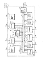
図1は、本発明の1実施形態によるデータ処理システム10をブロック図形式で示している。本発明の1実施形態において、データ処理システム10は、すべてバス20に双方向に結合されて情報のやりとりをスムーズに実行する複数のバス・マスタ12、14と、複数の共用資源24、30、100と、複数の非共用資源22、26を含んでいる。図1のこの実施形態において、バス・マスタ12、14は、プロセッサなどの1つのバス・マスタ、または1つ以上のプロセッサ、ならびにサポート回路(supporting circuit)を備えるサブシステムを表すことができる。共用資源24、30、100は、オプションとして複数のバス・マスタ12、14によって共用されることもあることに留意されたい。非共用資源22、26は、バス・マスタ12、14によって共用されず、したがってバス・マスタ12、14のうちの一方によってしかアクセスされない。本明細書中で使用している用語「バス」は、データ、アドレス、制御、ステータスなどの1つ以上の様々なタイプの情報を転送するために使用することができる複数の信号または導体を意味する。これらの用語「導体」および「信号」は、本明細書中では、交換可能なように使用される。本発明の1実施形態において、バス20は、1つ以上のバス・プロトコルを使用して実装される。バス調停ロジック28を使用して、バス・マスタ12と14の間の調停を行って、これら複数のバス・マスタ12、14のうちのどちらがバス20の支配権を有するかを決定する。
FIG. 1 illustrates in block diagram form a data processing system 10 according to one embodiment of the present invention. In one embodiment of the present invention, the data processing system 10 includes a plurality of
本発明の一部の実施形態においては、バス・マスタ12は、バス20を介するのでなく、導体48を介して1つ以上の非共用資源(例えば、16)に双方向に結合することができる。同様に、本発明の一部の実施形態においては、バス・マスタ14は、バス20を介するのでなく、導体49を介して1つ以上の非共用資源(例えば、18)に双方向に結合することができる。この例示の実施形態において、非共用資源16は、バス・マスタ12によってしかアクセスされず、バス・マスタ14によってはアクセスされない。同様に、非共用資源18は、バス・マスタ14によってしかアクセスされず、バス・マスタ12によってはアクセスされない。本発明の一部の実施形態は、データ処理システム10の外部にある外部バス34にバス20を結合することができる外部バス・インタフェイス32を含んでいる。本発明の1実施形態においては、データ処理システム10は、1つの集積回路上で実装される。本発明の代替実施形態は、任意の適切な回路を使用した任意の方法でデータ処理システム10を実装することができる。
In some embodiments of the invention, the
本発明の一部の実施形態においては、非共用資源16は、1つ以上の端子40を介してデータ処理システム10の外部にある回路に結合することができる。バス・マスタ12は、1つ以上の端子41を介してデータ処理システム10の外部にある回路に結合することができる。バス・マスタ14は、1つ以上の端子42を介してデータ処理システム10の外部にある回路に結合することができる。非共用資源18は、1つ以上の端子43を介してデータ処理システム10の外部にある回路に結合することができる。USB共用資源100は、1つ以上の端子48を介してデータ処理システム10の外部にある回路に結合することができる。非共用資源22は、1つ以上の端子44を介してデータ処理システム10の外部にある回路に結合することができる。共用資源24は、1つ以上の端子45を介してデータ処理システム10の外部にある回路に結合することができる。共用資源30は、1つ以上の端子46を介してデータ処理システム10の外部にある回路に結合することができる。また非共用資源26は、1つ以上の端子47を介してデータ処理システム10の外部にある回路に結合することができる。本発明の代替実施形態は、端子40〜48のうちの任意の組合せを使用してもよいし、また使用しなくてもよい。端子40〜48は、使用可能な任意の方法で実装することができる。
In some embodiments of the present invention, the
引き続き図1を参照すると、共用資源24は、バス・マスタ12および14によって共用することができる。また共用資源24は、どのバス・マスタによっても所有することができないか、またはバス・マスタ12および14のうちのどちらか一方だけによって所有することもできる。USB共用資源100は、パーティションに区分することができ、その結果、1つ以上の部分は、バス・マスタ12および14により共用することができる。また、USB共用資源100は、パーティションに区分することができ、その結果、1つ以上の部分は、どのバス・マスタによっても所有することができないか、またはバス・マスタ12および14のどちらか一方だけによって所有することもできる。本発明の様々な実施形態は、リセット後に所望の任意の方法で、共用資源またはその一部分の所有権を割り付けることができることに留意されたい。1実施例として、本発明の1実施形態では、USB共用資源100のすべての部分は、リセットから出てくることができ、その結果、所定の単1バス・マスタ(例えば、バス・マスタ12)は、所有権を有することになる。
With continued reference to FIG. 1, the shared
本発明のこの例示の実施形態においては、追加信号ステアリング・ロジック36を使用して、どのバス・マスタ、またはバス・マスタ12、14が、追加信号56、57のうちのどの1つ以上の信号を受け取るかを決定する。バス20に含まれるこれらの信号は、バス20によって実装されるバス・プロトコルによって定義される信号であることに留意されたい。追加信号56、57は、データ処理システム10中のバス・マスタ12、14のサブセットに対して選択的に提供することができる信号を含んでいる。本発明の代替実施形態においては、これらの1つ以上のバス信号を、バス・マスタ12、14のサブセットに選択的に提供する必要がある場合には、追加信号ステアリング・ロジック36を使用して、これらのバス信号20のうちの1つ以上の信号を方向付けすることができることに留意されたい。バス・マスタ12、14のサブセットは、ある種のケースではすべてのバス・マスタのフルセットを含むことができるが、一般的には、追加信号56、57はデータ処理システム10中においてこれらのバス・マスタ12、14のすべてに対するよりも少なく方向付けが行われる。信号50および51を使用して、追加信号56、57のステアリングについての制御および/またはステータスを実現する。
In this exemplary embodiment of the invention, additional
本発明のこの例示の実施形態においては、追加信号ステアリング・ロジック36は、追加信号57を受け取り、方向付けするために共用資源30に結合される。追加信号57は、共用資源30と適切なバス・マスタ12、14との間でそれぞれ信号53または52を介して追加信号ステアリング・ロジック36によって方向付ける必要がある1つ以上の信号を含んでいる。追加信号57は、所望の任意の機能を有することができるが、これらの信号は一般に、すべてのバス・マスタ12、14に対してほぼ同時に供給すべきではなく、その代わりにバス・マスタ12、14のサブセットに対してしか提供すべきでない信号である。追加信号57の1実施例は、共用資源30の所有権を有し、この割込みに対して応答する必要があるバス・マスタに対してしか方向付けされ供給されるべきでない割込み信号である。本発明の他の実施形態は、追加信号ステアリング・ロジック36を使用して、この全体のバス・マスタ(例えば、12、14)のサブセットに対して所望の任意の信号を方向付けすることができる。方向付けすることができる他の追加信号の一部の実施例は、リセット信号、DMA要求信号およびDMA認可信号、モード制御信号(例えば、電力制御モード)、カスタム・プロトコル・ハンドシェイク信号、プライベート・メッセージ・チャネル、ならびに1つ以上の他の所望の任意の信号である。本発明の一部の実施形態では、追加信号57のうちの1つ以上の信号を、選択された状況下においてこれらのバス・マスタ12、14のすべてに方向付けすることができる実施形態が存在し得ることに留意されたい。さらに、本発明の一部の実施形態では、信号52、53、56、および57のうちのどの信号も、双方向でなくてもよく、また一部の信号、またはすべての信号が双方向であってもよい。
In this exemplary embodiment of the invention, additional
追加信号ステアリング・ロジック36は、信号50を介して共用資源30に対して双方向に結合される。信号50は、追加信号57の方向付け(steering)において使用される制御情報および/またはステータス情報を提供するために使用される1つ以上の信号を含んでいる。本発明の代替実施形態は、任意のタイプの信号を使用してこの制御情報および/またはステータス情報を伝えることができる。すべての必要な制御情報および/またはステータス情報は、追加信号ステアリング・ロジック36中に存在し、あるいは別の方法で追加信号ステアリング・ロジック36に対して与えられるので、本発明の一部の実施形態は、信号50を必要としないこともある。
Additional
本発明のこの例示の実施形態において、追加信号ステアリング・ロジック36は、追加信号56を受け取り方向付けするために共用資源24に結合される。追加信号56は、共用資源24と適切なバス・マスタ12、14の間でそれぞれ信号53または52を介して追加信号ステアリング・ロジック36によって方向付けする必要がある1つ以上の信号を含んでいる。追加信号56は、所望の任意の機能を有することができるが、これらの信号は、一般的にすべてのバス・マスタ12、14に対してほぼ同時に供給すべきではなく、その代わりにバス・マスタ12、14のサブセットだけにしか供給すべきでない信号である。追加信号56の1つの可能な実施例は、共用資源24の所有権を有し、この割込みに応答する必要があるバス・マスタに対してしか方向付けされ供給されるべきでない割込み信号である。本発明の他の実施形態は、追加信号ステアリング・ロジック36を使用して、これらの全体のバス・マスタ(例えば、12、14)のサブセットに所望の任意の信号を方向付けすることができる。本発明の一部の実施形態では、選択された状況下において追加信号56のうちの1つ以上の信号をすべてのバス・マスタ12、14に対して方向付けすることができるシナリオが存在し得ることに留意されたい。
In this exemplary embodiment of the invention, additional
追加信号ステアリング・ロジック36は、信号51を介して共用資源24に対して双方向に結合される。信号51は、追加信号56の方向付けにおいて使用される制御情報および/またはステータス情報を提供するために使用される1つ以上の信号を含んでいる。本発明の代替実施形態は、任意のタイプの信号を使用して、この制御情報および/またはステータス情報を伝えることができる。すべての必要な制御情報および/またはステータス情報は、追加信号ステアリング・ロジック36中に存在し、あるいは別の方法で追加信号ステアリング・ロジック36に対して与えられるので、本発明の一部の実施形態は、信号51を必要としないこともある。
Additional
本発明の一部の実施形態においては、追加信号ステアリング・ロジック36によって実施されるステアリング機能のすべてまたは一部分は、共用資源それ自体の一部分として含めることができる。例えば、図1に示す実施形態において、信号101および102についてのステアリング機能は、USB共用資源100内の回路によって実施され、したがって信号101および102は、追加信号ステアリング・ロジック36を通過させて正しいバス・マスタ12、14に対して方向付けする必要はない。図1に示す本発明の実施形態においては、信号101を使用して、例えば割込みなどの1つ以上の追加信号をバス・マスタ12に対して供給することができる。同様に、信号102を使用して、例えば割込みなどの1つ以上の追加信号をバス・マスタ14に対して供給することができる。本発明の代替実施形態は、信号101および102を追加信号ステアリング・ロジック36に供給して、信号101および102をそれぞれ信号53および52を介してこの正しいバス・マスタ12、14に方向付けすることができる。
In some embodiments of the invention, all or a portion of the steering function performed by the additional
本発明のこの例示の実施形態においては、非共用資源22は、バス・マスタ12によってしかアクセスされず、したがって、非共用資源22に関連するこれらの追加信号は、信号54を介して直接にバス・マスタ12に双方向に結合される。信号54は、そもそも1つのバス・マスタ12に対してしか供給されないので、信号54は、追加信号ステアリング・ロジック36によって方向付けする必要はない。同様に、本発明のこの例示の実施形態においては、非共用資源26は、バス・マスタ14によってしかアクセスされず、したがって、非共用資源26に関連するこれらの追加信号は、信号55を介して直接にバス・マスタ14に双方向に結合される。信号55は、そもそも1つのバス・マスタ14に対してしか供給されないので、信号55は、追加信号ステアリング・ロジック36によって方向付けする必要はない。
In this exemplary embodiment of the present invention,
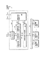
図2は、本発明の1実施形態による、図1の追加信号ステアリング・ロジック36の一部分をブロック図形式で示している。この例示の実施形態において、追加信号ステアリング・ロジック36は、信号56および57についての実際のステアリング機能を実施するステアリング回路60を含んでいる。信号56および57は、信号53を介してバス・マスタ12へ、または信号52を介してバス・マスタ14へと方向付けすることができる。信号50および51は、それぞれ共用資源30および24からの情報を提供する。制御回路62に提供され、または記憶される他の制御情報と一緒に信号50および51を使用して、ステアリング回路60によって実施されるステアリング機能を制御する。
FIG. 2 illustrates in block diagram form a portion of the additional
制御回路62は、レジスタ70を含んでいる。本発明の1実施形態においては、レジスタ70は、ステアリング・モード・セレクタ・レジスタ71、ステアリング・マップ・セレクタ・レジスタ72、マップ定義レジスタ73、マップ定義レジスタ74、および資源所有権レジスタ75を含んでいる。本発明の代替実施形態は、より多くの、より少ない、または異なるレジスタを使用して、ステアリング回路60を制御するための制御情報の一部分を提供することができる。本発明の1実施形態においては、レジスタ70の一部またはすべては、バス・マスタ12および14のうちの少なくとも一方によって読み取り、書き込むことができるソフトウェア・プログラマブル・レジスタである。
The control circuit 62 includes a register 70. In one embodiment of the present invention, register 70 includes a steering mode selector register 71, a steering
所望の任意の経路指定スキームは、追加信号56および57をこれら所望の1つ以上のバス・マスタ12、14に対して方向付けするために使用することができる。しかし、本発明のこの例示の実施形態においては、共用資源24、20ごとの少なくとも1つのステアリング・モード・セレクタ・レジスタ71、共用資源24、20ごとの少なくとも1つのステアリング・マップ・セレクタ・レジスタ72が存在し、また少なくとも1つのマップ定義レジスタ73、74が存在する。各ステアリング・モード・セレクタ・レジスタ71を使用して、その対応する共用資源24、30についての複数のステアリング・モードのうちの1つを選択することができる。この選択されたステアリング・モードは、次いでマップ定義レジスタ73、74のうちの一方に記憶されたマップ定義の使用を必要として、どの1つ以上のバス・マスタ12、14が、ステアリング回路60によって方向付けされる信号を受け取るべきかを決定することができる。各ステアリング・マップ・セレクタ・レジスタを使用して、複数のマップ定義レジスタ73、74のうちの一方を選択することができる。
Any desired routing scheme may be used to direct
本発明の1実施形態においては、追加信号56および57は、選択されているステアリング・モードに応じて、またオプションとしてマップ定義レジスタ73、74に記憶されるマップ定義に応じて、複数の方法でバス・マスタ12、14に経路指定することができる。例えば、1つのステアリング・モードは、この追加信号(例えば、56)を方向付けすることができ、その結果、この追加信号は、この共用資源(例えば、24)の所有権を現在有するバス・マスタ(例えば、12)に供給される。マップ定義レジスタは、このステアリング・モードでは、必要とされない。第2のステアリング・モードは、追加信号56、57を方向付けすることができ、その結果、この追加信号は、マップ定義レジスタ73、74の一方に記憶されるプログラマブル経路指定マップによって決定されるように1つ以上のバス・マスタ12、14に供給される。このプログラマブル経路指定マップは、1つ以上のバス・マスタ12、14によってプログラムすることができる。本発明の一部の実施形態においては、共用資源24、30の所有権を有するマスタしか、共用資源24、30に対応するマップ定義レジスタ73、74に書き込むことができず、したがってこれらを変更することができない。本発明の代替実施形態は、1つ以上のマップ定義のプログラミングを異なった方法で制御することができる。
In one embodiment of the present invention,
第3のステアリング・モードは、この追加信号(56または57のうちの一方)を方向付けすることができ、その結果、この追加信号は、マップ定義レジスタ73、74に記憶される複数のプログラマブル経路指定マップのうちの1つによって決定されるように、1つ以上のバス・マスタ12、14に供給される。このプログラマブル経路指定マップは、どちらのバス・マスタ12、14が、追加信号56、57を供給し、またはこれらの追加信号に関連する共用資源24、30の所有権を現在有するかに基づいて選択することができる。本発明の一部の実施形態においては、共用資源24、30の所有権を有するバス・マスタしか、この共用資源24、30に対応するマップ定義レジスタ73、74に書き込むことができず、したがってこれらを変更することができない。本発明の代替実施形態は、1つ以上のマップ定義のプログラミングを異なった方法で制御することができる。
The third steering mode can direct this additional signal (one of 56 or 57) so that the additional signal is stored in the map definition registers 73, 74 in a plurality of programmable paths. Provided to one or
第4のステアリング・モードは、この追加信号(56または57のうちの一方)を方向付けすることができ、その結果、この追加信号は、マップ定義レジスタ73、74に記憶される複数のプログラマブル経路指定マップのうちの1つによって決定されるように、1つ以上のバス・マスタ12、14に供給される。このプログラマブル経路指定マップは、追加信号56、57を供給し、またはこれらの追加信号に関連する共用資源24、30の現在の状態に基づいて選択することができる。本発明の一部の実施形態においては、マップ定義レジスタ73、74は、共用資源24、30のいくつかの状態のそれぞれに対応する静的マップとすることができる。本発明の他の実施形態においては、マップ定義レジスタ73、74は、1つ以上のバス・マスタ24、30(例えば、この所有しているマスタ)によってプログラム可能とすることもできる。本発明の一部の実施形態においては、共用資源24、30の所有権を有するバス・マスタしか、この共用資源24、30に対応するマップ定義レジスタ73、74に書き込むことができず、したがってこれらを変更することができない。本発明の代替実施形態は、1つ以上のマップ定義のプログラミングまたは確立を異なった方法で制御することができる。
The fourth steering mode can direct this additional signal (one of 56 or 57) so that this additional signal is stored in the map definition registers 73, 74 in multiple programmable paths. Provided to one or
第5のステアリング・モードは、この追加信号(56または57のうちの一方)を方向付けすることができ、その結果、この追加信号は、マップ定義レジスタ73、74に記憶される複数のプログラマブル経路指定マップのうちの1つによって決定されるように、1つ以上のバス・マスタ12、14に供給される。このプログラマブル経路指定マップは、追加信号56、57を供給し、またはこれらの追加信号に関連する共用資源24、30によって選択することができる。本発明の一部の実施形態においては、共用資源24、30それ自体しか、この共用資源24、30に対応するマップ定義レジスタ73、74に書き込むことができず、したがってこれらを変更することができない。本発明の代替実施形態は、1つ以上のマップ定義のプログラミングを異なった方法で制御することができる。
The fifth steering mode can direct this additional signal (one of 56 or 57) so that the additional signal is stored in the map definition registers 73, 74 in a plurality of programmable paths. Provided to one or
本発明の代替実施形態では、ステアリング回路60を制御するために使用される制御回路62についての所望の任意の構成を使用することができる。制御回路62の代替実施形態は、レジスタを有さなくてもよく、あるいは、より少ない、より多くの、または異なったレジスタ70を有していてもよい。制御回路62は、信号61を介してステアリング回路60に双方向に結合される。制御回路62は、バス20に双方向に結合され、その結果、レジスタ70は、例えば1つ以上のバス・マスタ12、14によって読み取り、書き込むことができる。本発明の1実施形態においては、信号50、51は、どの共用資源24、30が、信号56、57を供給し、またはこれらの信号に関連するか、どのステアリング・モードを使用するか、またどのマップ定義を使用するかに関連する情報を提供する。本発明の代替実施形態においては、信号50、51は、どの共用資源24、30が、信号56、57を供給し、またはこれらの信号に関連するかに関する情報を提供し、レジスタ70を使用して、このステアリング・モード情報およびマップ定義情報の残りをステアリング回路60に提供する。
In alternate embodiments of the present invention, any desired configuration for the control circuit 62 used to control the
図3は、他の回路と一緒に、本発明の1実施形態による、図1の共用資源24の一部分をブロック図形式で示している。本発明のこの例示の実施形態において、共用資源24は、バス20に双方向に結合されたバス・インタフェイス310を含んでいる。バス・インタフェイス310は、導体320によって再構成可能制御ロジック304に双方向に結合され、導体326によって再構成可能チャネル・ストレージ回路300に双方向に結合され、その結果、304および300内のレジスタおよび他の回路は、バス20を介して読取りアクセス可能および/または書込みアクセス可能とすることができる。1実施形態においては、再構成可能チャネル・ストレージ回路300は、再構成可能チャネル・ストレージ回路301〜303を含んでいる。本発明の代替実施形態は、再構成可能チャネル・ストレージ回路300内に、より少ない、より多い、または同じ数の再構成可能チャネル・ストレージ回路301〜303を有していてもよい。再構成可能チャネル・ストレージ回路300は、導体322を介して再構成可能制御ロジック304に双方向に結合される。本発明の1実施形態においては、信号322を使用して、再構成可能チャネル・ストレージ回路300と再構成可能制御ロジック304との間で、制御情報および/またはステータス情報を転送する。再構成可能チャネル・ストレージ回路300は、信号328を介して再構成可能チャネル回路312に双方向に結合される。再構成可能チャネル回路312は、導体324を介して、再構成可能制御ロジック304に双方向に結合される。再構成可能チャネル回路312は、導体45を介してバス330に双方向に結合される。
FIG. 3 illustrates, in block diagram form, a portion of the shared
図3に示す本発明の実施形態においては、ペリフェラル機能回路306〜308ごとに1つの再構成可能チャネル・ストレージ回路301〜303が存在する。本発明の代替実施形態は、ペリフェラル機能回路306〜308ごとに任意数の再構成可能チャネル・ストレージ回路301〜303を有することもできる。各ペリフェラル機能回路306〜308は、例えば、タイマ機能、通信機能、変換機能、データ処理機能、ストレージ機能など、1つ以上の任意タイプの所望の機能を実施することができる。さらに、本発明の一部の実施形態においては、再構成可能チャネル回路312は、再構成可能回路を含んでいて、例えば、タイマ機能、通信機能、変換機能、データ処理機能、ストレージ機能など、1つ以上の任意タイプの所望の機能を実施する。したがって、機能を実施する回路は、(例えば、再構成可能チャネル回路312中に配置することができる)共用資源24と同じ集積回路上に配置することもでき、あるいは代わりに(例えば、任意のペリフェラル機能回路306〜308中に配置することができる)共用資源24を組み込んでいる集積回路の外側に配置することもできる。
In the embodiment of the present invention shown in FIG. 3, there is one reconfigurable channel storage circuit 301-303 for each peripheral function circuit 306-308. Alternate embodiments of the present invention may have any number of reconfigurable channel storage circuits 301-303 for each peripheral function circuit 306-308. Each peripheral function circuit 306-308 can perform one or more arbitrary types of desired functions such as a timer function, a communication function, a conversion function, a data processing function, and a storage function, for example. Further, in some embodiments of the present invention, the
図3に示す本発明の実施形態においては、再構成可能制御ロジック304を使用して、追加信号ステアリング・ロジック36(図1参照)に対して信号56および信号51を供給する。また再構成可能制御ロジック304を使用して、バス・マスタ12、14のうちの一方から1つ以上のペリフェラル機能回路306〜308に対して使用される通信経路を決定し、または選択する。この通信経路は、バス20、バス・インタフェイス310、再構成可能チャネル・ストレージ回路301〜303のうちの1つ(どの1つかは再構成可能制御ロジック304によって決定される)、再構成可能チャネル回路312、信号45、およびバス330を使用する。
In the embodiment of the invention shown in FIG. 3,
本発明の1実施形態においては、再構成可能チャネル回路312を使用して、再構成可能チャネル・ストレージ回路300とペリフェラル機能回路306〜308の間の通信経路を決定し、または選択することに留意されたい。本発明の一部の実施形態においては、再構成可能チャネル回路312は、再構成可能制御ロジック304を介してプログラムされる。本発明の代替実施形態においては、再構成可能チャネル回路312は、バス・インタフェイス310を介してバス・マスタ12または14によってプログラムすることができる。本発明の一部の実施形態においては、再構成可能チャネル・ストレージ回路300は、再構成可能制御ロジック304によって再構成することができるストレージ回路としてもっぱら機能することができる。同様に再構成可能チャネル回路312は、この機能が、再構成可能制御ロジック304によって選択可能な所望の機能を実施するようにもっぱら機能することもできる。本発明の代替実施形態は、共用資源24のストレージ部分、機能部分、および制御部分をどのような方法でも、パーティションに区分することができる。本発明の代替実施形態は、再構成可能チャネル回路312を使用することができず、その代わりに再構成可能制御ロジック304を直接に使用して、再構成可能チャネル・ストレージ回路300とペリフェラル機能回路306〜308の間の通信経路を決定し、または選択することができることに留意されたい。
Note that in one embodiment of the invention,
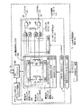
図4は、他の回路と一緒に、本発明の1実施形態による、図1のUSB共用資源100の一部分をブロック図形式で示している。1実施形態においては、USB共用資源100は、ユニバーサル・シリアル・バス(USB)規格に準拠し、USBバス43を介してUSBホスト420と情報をやりとりする。USB共用資源100はまた、バス20にも結合される。図4に示す本発明の実施形態においては、USB共用資源100は、エンドポイント・ストレージ回路470およびバス・インタフェイス400に双方向に結合されるUSB機能コントローラ413を含んでいる。バス・インタフェイス400は、エンドポイント・ストレージ回路470に双方向に結合され、バス20に双方向に結合される。本発明の1実施形態においては、USB機能コントローラ413は、USBプロトコル・ロジック415を介してシリアル・インタフェイス・エンジン418に双方向に結合される。シリアル・インタフェイス・エンジン418は、USBバス43に双方向に結合される。
FIG. 4 illustrates, in block diagram form, a portion of the USB shared
本発明の1実施形態においては、USB機能コントローラ413は、USBプロトコル・ロジック415に結合される複数のUSB機能制御レジスタ402を含んでいる。USBプロトコル・ロジック415は、エンドポイント割込みロジック417に結合されて、いつ割込みをバス・マスタ12、14に提供すべきかに関する割込み情報を提供する。ステアリング・ロジック480は、エンドポイント割込みロジック417およびUSB機能制御レジスタ402からの情報を受け取り、それに応答して割込み信号101および102をそれぞれバス・マスタ12および14に提供する。追加信号ステアリング・ロジック36を使用してどのバス・マスタ12、14がどの追加信号を受け取るかを決定する共用資源24(図1参照)と違って、USB共用資源100は、このステアリング機能を実施するための回路を含んでいる。その結果、信号101および102は、追加信号ステアリング・ロジック36を介して経路指定する必要がなくなる。追加信号ステアリング・ロジック36によって実現されるこのステアリング機能は、USB共用資源100内で実施される。
In one embodiment of the invention, the
本発明の1実施形態においては、ステアリング・ロジック480は、それぞれ、1入力がUSB機能制御レジスタ402に結合され、1入力がエンドポイント割込みロジック417に結合されているANDゲート422、424、426、および428を含んでいる。ステアリング・ロジック480はまた、ANDゲート422、424、426、および428からの入力を受け取り、出力101および102をそれぞれバス・マスタ12、14に供給する複数のORゲート430、432も含んでいる。
In one embodiment of the present invention, steering logic 480 includes AND
本発明の1実施形態においては、各エンドポイントは、対応するビット460または462、対応するラッチ410または412、対応するビット450または452、およびエンドポイント割込みロジックの対応する一部分440または442を有する。図4に示す特定の回路は、単に例示の目的で示されているにすぎないことに留意されたい。本発明の代替実施形態では、適切な任意の回路を使用して、USB機能コントローラ413によって必要とされるステアリング機能を実装することができる。
In one embodiment of the invention, each endpoint has a
本発明の1実施形態においては、USB機能制御レジスタ402は、割込みステアリング・レジスタ403、他の共用レジスタ414、および非共用レジスタ416を含んでいる。本発明の1実施形態においては、割込みステアリング・レジスタ403は、割込みステアリング・ストレージ回路408に結合されて、セット信号およびリセット信号を供給して、それぞれラッチ410、412をセット/リセットする割込みステアリング・セット・レジスタ406および割込みステアリング・クリア・レジスタ404を含んでいる。本発明の代替実施形態は、割込みステアリング・レジスタ403を実装するために使用される方法と同様にしてセット・レジスタ、クリア・レジスタ、および複数のセット/リセット・ラッチを使用して実装される複数の他の共用レジスタ414を含むことができる。
In one embodiment of the invention, the USB function control register 402 includes an interrupt
共用レジスタ403および414、エンドポイント割込みロジック417、ならびにステアリング・ロジック480の使用を介して、USB機能コントローラ413は、マルチマスタ・システム中のエンドポイントの共用制御を可能にする機能を有することに留意されたい。図1に示すマルチマスタ・システムは、2つのバス・マスタ12、14を使用しているが、本発明の代替実施形態は、データ処理システム10の外部にあるバス・マスタを含めて、任意数または任意タイプのバス・マスタを使用することもできる。
Note that through the use of shared
次にUSB共用資源100の機能について、さらに詳細に説明することにする。USBプロトコル・ロジック415は、シリアル・インタフェイス・エンジン418に対してデータを提供し、またそこからデータを受け取る。シリアル・インタフェイス・エンジン418は、USBホスト420に対してデータを提供し、そこからデータを受け取り、このUSB規格に従って機能する。
Next, the function of the USB shared
本発明の1実施形態においては、USB共用資源100は、所有されていない共用資源であると考えられる。しかし、USB共用資源100は、パーティションに区分され、その結果、1つ以上の部分(例えば、USBエンドポイント)を異なるバス・マスタ12および14に割り付けることができる。本発明の1実施形態においては、これらのUSBエンドポイントは、エンドポイント・ストレージ回路470に記憶することができる。本発明の1実施形態においては、割込みステアリング・レジスタ403を追加して、エンドポイント割込みを複数のバス・マスタ12、14のうちの一方に方向付けしている。
In one embodiment of the present invention, USB shared
本発明のこの例示の実施形態においては、割込みステアリング・レジスタ403は、割込みステアリング・セット・レジスタ406、割込みステアリング・クリア・レジスタ404、および割込みステアリング・ストレージ回路408を使用して実装されている。この例示の実施形態においては、バス・マスタ12、14の選択を指定してこの割込みを受け取る2つのロジック状態しか使用可能ではない。したがって、この例示の実施形態では、エンドポイント割込みは、たった2つのバス・マスタ12、14のうちの1つに対してしか方向付けすることができない。しかし、本発明の代替実施形態は、割込みステアリング・レジスタ403を実装することができ、その結果、エンドポイント割込みを複数のバス・マスタに対して方向付けすることができる。本発明のこの例示の実施形態においては、割込みステアリング・セット・レジスタ406も割込みステアリング・クリア・レジスタ404も共に、このメモリ・マップ/プログラマのモデル中のレジスタであり、バス20およびバス・インタフェイス400を介して書き込むことができることに留意されたい。レジスタ406および404の読取りは、本発明のこの例示の実施形態においては、使用されないが、本発明の代替実施形態は、所望のどのような方法でもレジスタ406および404の読取りを扱うことができることに留意されたい。
In this exemplary embodiment of the invention, interrupt steering
本発明の1実施形態においては、バス・マスタ12も14も共に、共用レジスタ414および割込みステアリング・レジスタ403に書き込み、これらを修正することができる。これは、レジスタ414および403の内容の破損をもたらすこともあることに留意されたい。このメモリ・マップ/プログラマのモデル中の一意のアドレスに配置される別の割込みステアリング・セット・レジスタ406の使用と、このメモリ・マップ中の異なるアドレスに配置される別の割込みステアリング・クリア・レジスタ404の使用により、複数のバス・マスタ12、14は、レジスタ403中の非選択ビットに影響を及ぼすことなく、レジスタ403中の選択されたビットを独立にセットし、またはクリアすることができるようになる。本発明の一部の実施形態では、1つ以上の他の共用レジスタ414をレジスタ403と同様にして(すなわち、別々のセット・レジスタおよびクリア・レジスタ406、404を使用して)実装することができることに留意されたい。例えば、エンドポイント・オペレーションに関連した他の共用レジスタ414のすべてまたは一部分は、レジスタ403と同様にして実装することができる。本発明の代替実施形態は、レジスタ401、および1つ以上のレジスタ414の内容の破損を回避する異なるメカニズムを使用することもできる。かかるメカニズムの1実施例は、レジスタ402および414に対する原子読取り修正書込みアクセス(atomic read−modify−write access)である。
In one embodiment of the present invention, both
本発明のこの例示の実施形態において、ビット460に対する「1」の書込みは、対応するラッチ410をセットすることになり、ビット460に対する「0」の書込みは、ラッチ410に対して影響を及ぼさないことになる。同様に、ビット450に対する「1」の書込みは、対応するラッチ410をクリアすることになり、ビット450に対する「0」の書込みは、ラッチ410に対して影響を及ぼさないことになる。このメカニズムは、バス・マスタ12とバス・マスタ14の両方によるレジスタ403のビットごとの制御を可能にすることに留意されたい。USB共用資源100を使用した一部の用途では、バス・マスタ12は、レジスタ・ビット403の一部分をセットすることになり、バス・マスタ14は、レジスタ・ビット403のオーバーラップしていない異なる部分をクリアすることになる。この場合には、レジスタ403のビット中の「1」は、この対応するエンドポイント割込みをバス・マスタ12へと方向付けし、レジスタ403のビット中の「0」は、この対応するエンドポイント割込みをバス・マスタ14へと方向付けする。
In this exemplary embodiment of the invention, writing a “1” to bit 460 will set the
本発明の1実施形態では、非共用レジスタ416は、複数のバス・マスタ12、14を用いて適切に動作するように修正する必要はない。例えば、非共用レジスタ416中のあるレジスタは、読取り専用にすることができ、非共用レジスタ416中の他のレジスタは、所定のソフトウェア規定によって指定されるように1つのバス・マスタ12、14によってアクセスすることができる。
In one embodiment of the present invention, the non-shared register 416 need not be modified to operate properly with
本発明の1実施形態においては、USBプロトコル・ロジック415およびエンドポイント割込みロジック417は、複数のマスタ使用のために修正する必要はない。しかし、エンドポイント割込みロジック417によって提供されるこれらの割込み出力は、今やレジスタ403の対応するビットによって指定されるバス・マスタへとステアリング・ロジック480によって方向付けされる必要がある。ステアリング・ロジック480は、どのような方法でも実装することができ、図4に示す回路は、ただステアリング・ロジック480の1つの可能性のある実装形態にすぎない。1つのバス・マスタ(例えば12または14)しか、USB共用資源100を利用していなかった場合には、ステアリング・ロジック480は、必要とされないはずであることに留意されたい。この場合には、すべての割込みがこの1つのバス・マスタに進むはずなので、方向付けは必要とされないはずである。
In one embodiment of the present invention,
図4に示す残りの回路は、標準のUSB回路と同様にして機能することができる。
前述の明細書では、特定の実施形態に関して本発明を説明している。しかし、添付の特許請求の範囲で述べる本発明の範囲を逸脱することなく、様々な修正および変更を行うことができることが、当業者には理解されよう。したがって、この明細書および図面は、限定的な意味ではなくて例示的な意味で考慮すべきであり、すべてのかかる修正形態は、本発明の範囲内に含めるべきであることが意図されている。
The remaining circuits shown in FIG. 4 can function in the same way as standard USB circuits.
In the foregoing specification, the invention has been described with reference to specific embodiments. However, one of ordinary skill in the art appreciates that various modifications and changes can be made without departing from the scope of the present invention as set forth in the claims below. The specification and drawings are, accordingly, to be regarded in an illustrative sense rather than a restrictive sense, and all such modifications are intended to be included within the scope of the present invention. .
利点、他の長所、および問題に対する解決法について、特定の実施形態に関して以上で説明してきている。しかし、どのような利点、長所、または解決方法をも引き起こし、より明確になるようにさせ得るこれらの利点、長所、問題に対する解決法、および1つ(または複数)のどのような要素も、任意の請求項またはすべての請求項の重要な、必要な、あるいは必須の特徴または要素として解釈すべきではない。本明細書中で使用しているように、用語「からなる(含む)(comprises)」、「からなる(含む)(comprising)」またはこの任意の他の変形は、要素のリストを含む工程、方法、物、または装置が、これらの要素を含むだけでなく、かかる工程、方法、物、または装置に明示的にリストアップされない、または固有の他の要素も含むことができるように、非排他的包含を範囲に含むことを意図している。 Benefits, other advantages, and solutions to problems have been described above with regard to specific embodiments. However, any of these benefits, advantages, solutions to problems, and any one (or more) elements that can cause any advantage, advantage, or solution to be clearer are optional Should not be construed as critical, necessary, or essential features or elements of any claim or any claim. As used herein, the terms “comprises”, “comprising” or any other variant thereof includes a list of elements, Non-exclusive so that a method, article, or device not only includes these elements, but may also include other elements not explicitly listed or inherent in such steps, methods, articles, or devices It is intended to include inclusive coverage.
追加テキスト(1)
〔請求項1〕 システム・バスと、
該システム・バスに結合された第1のバス・マスタと、
該システム・バスに結合された第2のバス・マスタと、
該システム・バスに結合され、該第1のバス・マスタおよび該第2のバス・マスタのうちの少なくとも一方のバス・マスタによって所有されるように構成可能な資源と、
該資源と、該第1のバス・マスタおよび該第2のバス・マスタのうちの少なくとも一方のバス・マスタとの間で、該資源の所有権に基づいて通信経路を確立する追加信号ステアリング・ロジックと、
からなり、該通信経路を使用して、該資源と、該第1のバス・マスタおよび該第2のバス・マスタのうちの該少なくとも一方のバス・マスタとの間で、少なくとも1つの追加信号を転送するデータ処理システム。
Additional text (1)
[Claim 1] A system bus;
A first bus master coupled to the system bus;
A second bus master coupled to the system bus;
Resources coupled to the system bus and configurable to be owned by a bus master of at least one of the first bus master and the second bus master;
An additional signal steering to establish a communication path between the resource and at least one of the first bus master and the second bus master based on ownership of the resource Logic and
At least one additional signal between the resource and the at least one of the first bus master and the second bus master using the communication path Transfer data processing system.
〔請求項2〕 前記データ処理システムが、前記資源の所有権を示す資源所有権ストレージ回路をさらに備える、請求項1に記載のデータ処理システム。
〔請求項3〕 前記資源所有権ストレージ回路は、前記第1のバス・マスタが前記資源を所有するかどうか、前記第2のバス・マスタが前記資源を所有するかどうか、および前記第1のバス・マスタも前記第2のバス・マスタも前記資源を所有しないかどうかのうちの少なくとも1つを示す、請求項2に記載のデータ処理システム。
[Claim 2] The data processing system according to
3. The resource ownership storage circuit may determine whether the first bus master owns the resource, whether the second bus master owns the resource, and the first bus master. The data processing system of claim 2, wherein at least one of whether neither the bus master nor the second bus master owns the resource.
〔請求項4〕 前記第1のバス・マスタも前記第2のバス・マスタも共に前記資源の所有権を請求するときに、前記資源所有権ストレージ回路は、前記資源が所有されていないことを示す、請求項2に記載のデータ処理システム。 [Claim 4] When both the first bus master and the second bus master request ownership of the resource, the resource ownership storage circuit indicates that the resource is not owned. A data processing system according to claim 2, shown.
〔請求項5〕 前記第1のバス・マスタも前記第2のバス・マスタも前記資源の所有権を請求しないときに、前記資源所有権ストレージ回路は、前記資源が所有されていないことを示す、請求項2に記載のデータ処理システム。 [Claim 5] When neither the first bus master nor the second bus master claims ownership of the resource, the resource ownership storage circuit indicates that the resource is not owned. The data processing system according to claim 2.
〔請求項6〕 前記追加信号ステアリング・ロジックが、前記資源所有権ストレージ回路内に記憶される情報に基づいて前記通信経路を確立する、請求項2に記載のデータ処理システム。 6. The data processing system of claim 2, wherein the additional signal steering logic establishes the communication path based on information stored in the resource ownership storage circuit.
〔請求項7〕 前記追加信号ステアリング・ロジックが、前記資源と、前記第1のバス・マスタおよび前記第2のバス・マスタのうちの一方のバス・マスタだけとの間で前記通信経路を確立する、請求項1に記載のデータ処理システム。
7. The additional signal steering logic establishes the communication path between the resource and only one of the first bus master and the second bus master. The data processing system according to
〔請求項8〕 前記追加信号ステアリング・ロジックが、前記資源と、前記第1のバス・マスタおよび前記第2のバス・マスタのうちのそれぞれとの間で前記通信経路を確立する、請求項1に記載のデータ処理システム。 8. The additional signal steering logic establishes the communication path between the resource and each of the first bus master and the second bus master. The data processing system described in 1.
〔請求項9〕 前記少なくとも1つの追加信号が、前記システム・バスの一部分ではない、請求項1に記載のデータ処理システム。
〔請求項10〕 前記システム・バスが、システム・バス・プロトコルに従って動作し、前記少なくとも1つの追加信号が、該システム・バス・プロトコルの外側で動作する、請求項1に記載のデータ処理システム。
9. The data processing system of
10. The data processing system of
〔請求項11〕 前記資源からなるペリフェラルをさらに含む、請求項1に記載のデータ処理システム。
〔請求項12〕 前記ペリフェラルが、第2の資源からなり、前記追加信号ステアリング・ロジックが、該第2の資源に関連する少なくとも1つの追加信号を転送するために、該第2の資源と、前記第1のバス・マスタおよび前記第2のバス・マスタのうちの少なくとも一方のバス・マスタとの間で該第2の資源の所有権に基づいて第2の通信経路を確立する、請求項11に記載のデータ処理システム。
[Claim 11] The data processing system according to
12. The peripheral comprises a second resource, and the additional signal steering logic is configured to transfer at least one additional signal associated with the second resource, 2. A second communication path is established between at least one of the first bus master and the second bus master based on ownership of the second resource. 11. A data processing system according to 11.
〔請求項13〕 前記システム・バスに結合された第2の資源をさらに含み、前記追加信号ステアリング・ロジックが、該第2の資源に関連する少なくとも1つの追加信号を転送するために、該第2の資源と、前記第1のバス・マスタおよび前記第2のバス・マスタのうちの少なくとも一方のバス・マスタとの間で該第2の資源の所有権に基づいて第2の通信経路を確立する、請求項1に記載のデータ処理システム。
13. A second resource coupled to the system bus, the additional signal steering logic for transferring at least one additional signal associated with the second resource. A second communication path between the two resources and at least one of the first bus master and the second bus master based on ownership of the second resource. The data processing system of
〔請求項14〕 前記追加信号ステアリング・ロジックが、前記資源と、前記第1のバス・マスタおよび前記第2のバス・マスタのうちの、前記資源を所有している所有するバス・マスタとの間で通信経路を確立する、請求項1に記載のデータ処理システム。
14. The additional signal steering logic may comprise the resource and an owning bus master that owns the resource of the first bus master and the second bus master. The data processing system according to
〔請求項15〕 前記追加信号ステアリング・ロジックが、マップ定義を記憶するマップ・ストレージ回路からなり、前記追加信号ステアリング・ロジックが、該マップ定義に基づいて前記通信経路を確立する、請求項1に記載のデータ処理システム。
15. The method of
〔請求項16〕 前記マップ定義が、前記第1のバス・マスタおよび前記第2のバス・マスタのうちの、前記資源を所有している所有するバス・マスタによってプログラム可能である、請求項15に記載のデータ処理システム。 16. The map definition is programmable by an owning bus master that owns the resource of the first bus master and the second bus master. The data processing system described in 1.
〔請求項17〕 前記マップ・ストレージ回路が、複数のマップ定義を記憶し、前記追加信号ステアリング・ロジックが、前記資源の所有権に基づいて選択される該複数のマップ定義のうちの1つのマップ定義に基づいて前記通信経路を確立する、請求項15に記載のデータ処理システム。 17. The map storage circuit stores a plurality of map definitions, and the additional signal steering logic is one map of the plurality of map definitions selected based on ownership of the resource. The data processing system according to claim 15, wherein the communication path is established based on a definition.
〔請求項18〕 前記複数のマップ定義のうちの前記1つのマップ定義は、前記第1のバス・マスタが前記資源を所有するかどうか、前記第2のバス・マスタが、前記資源を所有するかどうか、および前記資源が所有されないかどうかのうちの少なくとも1つに基づいて選択される、請求項17に記載のデータ処理システム。 18. The one map definition of the plurality of map definitions includes: whether the first bus master owns the resource, and whether the second bus master owns the resource. The data processing system of claim 17, wherein the data processing system is selected based on at least one of whether and whether the resource is not owned.
〔請求項19〕 前記資源が、前記追加信号ステアリング・ロジックの少なくとも一部分からなる、請求項1に記載のデータ処理システム。
〔請求項20〕 システム・バスを有するデータ処理システムにおいて追加信号を伝えるための方法であって、
該システム・バスに結合された資源と、該システム・バスに結合された複数のバス・マスタのうちの少なくとも1つのバス・マスタとの間で該資源の所有権に基づいて通信経路を確立すること、および
該資源と、該複数のバス・マスタのうちの該少なくとも1つのバス・マスタとの間で、該通信経路を介して該システム・バスとは別の該追加信号を転送すること、
からなる方法。
19. The data processing system of
20. A method for communicating additional signals in a data processing system having a system bus comprising:
Establishing a communication path between resources coupled to the system bus and at least one bus master of the plurality of bus masters coupled to the system bus based on ownership of the resources And transferring the additional signal separate from the system bus via the communication path between the resource and the at least one bus master of the plurality of bus masters;
A method consisting of:
〔請求項21〕 前記通信経路を確立することが、
前記複数のバス・マスタから、前記資源を所有している所有するバス・マスタを決定すること、および
前記資源と、該所有するバス・マスタとの間で前記通信経路を確立すること、
からなる、請求項20に記載の方法。
[Claim 21] Establishing the communication path comprises:
Determining an owning bus master that owns the resource from the plurality of bus masters; and establishing the communication path between the resource and the owning bus master;
21. The method of
〔請求項22〕 前記通信経路を確立することが、
前記資源が前記複数のバス・マスタのうちのどれかによって所有されないときに、前記資源と、前記バス・マスタのうちの前記少なくとも1つのバス・マスタとの間で前記複数のバス・マスタのうちの第1のバス・マスタによって定義されるマップ定義に基づいて前記通信経路を確立することをさらに含む、請求項21に記載の方法。
[Claim 22] Establishing the communication path comprises:
Among the plurality of bus masters between the resource and the at least one bus master of the bus masters when the resource is not owned by any of the plurality of bus masters. 23. The method of claim 21, further comprising establishing the communication path based on a map definition defined by a first bus master.
〔請求項23〕 前記通信経路を確立することが、
前記資源と、前記複数のバス・マスタのうちの前記少なくとも1つのバス・マスタの間で、前記複数のバス・マスタのうちの、前記資源を所有している所有するバス・マスタによって定義されるマップ定義に基づいて前記通信経路を確立することからなる、請求項20に記載の方法。
(Claim 23) Establishing the communication path comprises:
Defined between the resource and the at least one bus master of the plurality of bus masters by the owning bus master owning the resource of the plurality of bus masters. 21. The method of
〔請求項24〕 前記通信経路を確立することが、
前記資源の所有権に基づいて複数のマップ定義のうちの1つのマップ定義を選択すること、および
前記資源と、前記複数のバス・マスタのうちの前記少なくとも1つのバス・マスタとの間で、該複数のマップ定義のうちの該選択される1つのマップ定義に基づいて前記通信経路を確立すること、からなる、請求項20に記載の方法。
(Claim 24) Establishing the communication path comprises:
Selecting one map definition of a plurality of map definitions based on ownership of the resource; and between the resource and the at least one bus master of the plurality of bus masters; 21. The method of
〔請求項25〕 システム・バスと、
該システム・バスに結合された第1のバス・マスタと、
該システム・バスに結合された第2のバス・マスタと、
該システム・バスに結合され、該第1のバス・マスタおよび該第2のバス・マスタによって使用可能であり、該第1のバス・マスタおよび該第2のバス・マスタのうちの少なくとも一方のバス・マスタによって所有されるように構成可能な資源と、
該資源と、該第1のバス・マスタおよび該第2のバス・マスタのうちの少なくとも一方のバス・マスタとの間で、通信経路を確立する追加信号ステアリング・ロジックと、
からなり、該通信経路を使用して、該資源と、該第1のバス・マスタおよび該第2のバス・マスタのうちの該少なくとも一方のバス・マスタとの間で、少なくとも1つの追加信号を転送し、該通信経路が、該資源によって決定されるデータ処理システム。
25. A system bus;
A first bus master coupled to the system bus;
A second bus master coupled to the system bus;
Coupled to the system bus and usable by the first bus master and the second bus master, and at least one of the first bus master and the second bus master Resources configurable to be owned by the bus master; and
Additional signal steering logic establishing a communication path between the resource and at least one of the first bus master and the second bus master;
At least one additional signal between the resource and the at least one of the first bus master and the second bus master using the communication path A data processing system in which the communication path is determined by the resource.
〔請求項26〕 前記通信経路が、前記資源の現在の状態によって決定される、請求項25に記載のデータ処理システム。
〔請求項27〕 前記資源の前記現在の状態が、前記資源の動作モードからなる、請求項26に記載のデータ処理システム。
26. The data processing system according to claim 25, wherein the communication path is determined by a current state of the resource.
27. The data processing system according to
〔請求項28〕 前記通信経路が、前記資源によって定義されるマップ定義に基づいて決定される、請求項25に記載のデータ処理システム。
〔請求項29〕 前記追加信号ステアリング・ロジックが、前記マップ定義を記憶するマップ定義ストレージ回路からなる、請求項28に記載のデータ処理システム。
28. The data processing system according to claim 25, wherein the communication path is determined based on a map definition defined by the resource.
29. The data processing system of
〔請求項30〕 前記追加信号ステアリング・ロジックが、前記資源と、前記第1のバス・マスタと前記第2のバス・マスタの両方との間で、前記通信経路を確立する、請求項25に記載のデータ処理システム。 30. The method of claim 25, wherein the additional signal steering logic establishes the communication path between the resource and both the first bus master and the second bus master. The data processing system described.
〔請求項31〕 前記少なくとも1つの追加信号が、前記システム・バスの一部分ではない、請求項25に記載のデータ処理システム。
〔請求項32〕 前記システム・バスが、システム・バス・プロトコルに従って動作し、前記少なくとも1つの追加信号が、該システム・バス・プロトコルの外側で動作する、請求項25に記載のデータ処理システム。
31. The data processing system of claim 25, wherein the at least one additional signal is not part of the system bus.
32. The data processing system of claim 25, wherein the system bus operates according to a system bus protocol and the at least one additional signal operates outside the system bus protocol.
〔請求項33〕 前記資源が、前記追加信号ステアリング・ロジックの少なくとも一部分からなる、請求項25に記載のデータ処理システム。
〔請求項34〕 システム・バスを有するデータ処理システムにおいて追加信号を伝えるための方法であって、
該システム・バスに結合された資源と、該システム・バスに結合された複数のバス・マスタのうちの少なくとも1つのバス・マスタとの間で、該資源によって決定される通信経路を確立すること、および
該資源と、該複数のバス・マスタのうちの該少なくとも1つのバス・マスタとの間で、該通信経路を介して該システム・バスとは別の該追加信号を転送すること、
からなる方法。
33. The data processing system of claim 25, wherein the resource comprises at least a portion of the additional signal steering logic.
34. A method for communicating additional signals in a data processing system having a system bus comprising:
Establishing a communication path determined by the resource between the resource coupled to the system bus and at least one bus master of the plurality of bus masters coupled to the system bus; Transferring the additional signal separate from the system bus via the communication path between the resource and the at least one bus master of the plurality of bus masters;
A method consisting of:
〔請求項35〕 前記通信経路を確立することが、
前記資源の現在の状態を決定すること、および
前記資源の該現在の状態に基づいて前記通信経路を確立すること、
からなる、請求項34に記載の方法。
(Claim 35) Establishing the communication path comprises:
Determining a current state of the resource; and establishing the communication path based on the current state of the resource;
35. The method of claim 34, comprising:
〔請求項36〕 前記通信経路を確立することが、
前記資源によって定義されるマップ定義を提供すること、および
該マップ定義に基づいて前記通信経路を確立すること、
からなる、請求項34に記載の方法。
(Claim 36) Establishing the communication path comprises:
Providing a map definition defined by the resource; and establishing the communication path based on the map definition;
35. The method of claim 34, comprising:
追加テキスト(2)
〔請求項1〕 第1のバス・マスタと、
第2のバス・マスタと、
該第1のバス・マスタおよび該第2のバス・マスタによりアクセス可能な共用再構成可能資源と、
からなり、該共用再構成可能資源が、該第1のバス・マスタおよび該第2のバス・マスタのうちの少なくとも一方のバス・マスタと、複数のペリフェラル機能から選択される第1のペリフェラル機能を実施するための回路との間で、通信経路を確立するデータ処理システム。
Additional text (2)
[Claim 1] A first bus master;
A second bus master;
A shared reconfigurable resource accessible by the first bus master and the second bus master;
And the shared reconfigurable resource is selected from a plurality of peripheral functions and at least one of the first bus master and the second bus master. A data processing system for establishing a communication path with a circuit for implementing the above.
〔請求項2〕 前記共用再構成可能資源が、前記第1のペリフェラル機能を実施するための前記回路の少なくとも一部分からなる再構成可能チャネル回路からなる、請求項1に記載のデータ処理システム。
[Claim 2] The data processing system according to
〔請求項3〕 前記共用再構成可能資源が、前記第1のペリフェラル機能を実施する際に使用するための前記再構成可能チャネル回路によりアクセス可能な再構成可能チャネル・ストレージからなる、請求項2に記載のデータ処理システム。 3. The shared reconfigurable resource comprises reconfigurable channel storage accessible by the reconfigurable channel circuit for use in performing the first peripheral function. The data processing system described in 1.
〔請求項4〕 前記再構成可能チャネル回路が、前記複数のペリフェラル機能から選択される第2のペリフェラル機能を実施するように構成可能である、請求項2に記載のデータ処理システム。 [Claim 4] The data processing system according to claim 2, wherein the reconfigurable channel circuit is configurable to implement a second peripheral function selected from the plurality of peripheral functions.
〔請求項5〕 前記共用再構成可能資源が、前記第1のバス・マスタおよび前記第2のバス・マスタのうちの少なくとも一方のバス・マスタと、前記第2のペリフェラル機能を実施するための回路との間で、第2の通信経路を確立し、前記再構成可能チャネル回路が、前記第2のペリフェラル機能を実施するための該回路の少なくとも一部分からなる、請求項4に記載のデータ処理システム。 [Claim 5] The shared reconfigurable resource performs at least one of the first bus master and the second bus master with the second peripheral function. 5. The data processing of claim 4, wherein a second communication path is established with a circuit, and the reconfigurable channel circuit comprises at least a portion of the circuit for performing the second peripheral function. system.
〔請求項6〕 前記第2のペリフェラル機能を実施するための前記回路が、シリアル・ペリフェラル・インタフェイス(SPI)、ユニバーサル非同期式レシーバ/トランスミッタ(UART)、ユニバーサル・シリアル・バス(USB)、入力キャプチャ、出力比較、汎用入出力、タイマ、および同期式シリアル・インタフェイス(SSI)のうちの少なくとも1つからなる、請求項5に記載のデータ処理システム。 [Claim 6] The circuit for performing the second peripheral function includes a serial peripheral interface (SPI), a universal asynchronous receiver / transmitter (UART), a universal serial bus (USB), an input 6. The data processing system of claim 5, comprising at least one of capture, output comparison, general purpose input / output, timer, and synchronous serial interface (SSI).
〔請求項7〕 前記データ処理システムが、前記共用再構成可能資源に結合された第1のペリフェラル機能回路をさらに備え、該第1のペリフェラル機能回路が、前記第1のペリフェラル機能を実施するための前記回路の少なくとも第1の部分からなる、請求項1に記載のデータ処理システム。
7. The data processing system further comprises a first peripheral function circuit coupled to the shared reconfigurable resource, the first peripheral function circuit performing the first peripheral function. The data processing system of
〔請求項8〕 前記共用再構成可能資源が、前記第1のペリフェラル機能を実施するための前記回路の少なくとも第2の部分からなる、請求項7に記載のデータ処理システム。
8. The data processing system of
〔請求項9〕 前記共用再構成可能資源が、前記第1のバス・マスタおよび前記第2のバス・マスタのうちの少なくとも一方のバス・マスタと、前記複数のペリフェラル機能から選択される第2のペリフェラル機能を実施するための回路との間で、第2の通信経路を確立する、請求項8に記載のデータ処理システム。 [Claim 9] The shared reconfigurable resource is selected from at least one of the first bus master and the second bus master and the plurality of peripheral functions. The data processing system according to claim 8, wherein a second communication path is established with a circuit for performing the peripheral function.
〔請求項10〕 前記データ処理システムが、前記共用再構成可能資源に結合された第2のペリフェラル機能回路をさらに備え、該第2のペリフェラル機能回路が、前記第2のペリフェラル機能を実施するための前記回路の少なくとも第1の部分からなり、前記共用再構成可能資源が、前記第2のペリフェラル機能を実施するための前記回路の少なくとも第2の部分からなる、請求項9に記載のデータ処理システム。 10. The data processing system further comprises a second peripheral function circuit coupled to the shared reconfigurable resource, wherein the second peripheral function circuit performs the second peripheral function. 10. The data processing of claim 9, comprising at least a first portion of the circuit, and wherein the shared reconfigurable resource comprises at least a second portion of the circuit for performing the second peripheral function. system.
〔請求項11〕 前記第2のペリフェラル機能を実施するための前記回路が、シリアル・ペリフェラル・インタフェイス(SPI)、ユニバーサル非同期式レシーバ/トランスミッタ(UART)、ユニバーサル・シリアル・バス(USB)、入力キャプチャ、出力比較、汎用入出力、タイマ、および同期式シリアル・インタフェイス(SSI)のうちの少なくとも1つからなる、請求項8に記載のデータ処理システム。 11. The circuit for performing the second peripheral function includes a serial peripheral interface (SPI), a universal asynchronous receiver / transmitter (UART), a universal serial bus (USB), an input 9. The data processing system of claim 8, comprising at least one of capture, output comparison, general purpose input / output, timer, and synchronous serial interface (SSI).
〔請求項12〕 前記第1のペリフェラル機能を実施するための前記回路が、シリアル・ペリフェラル・インタフェイス(SPI)、ユニバーサル非同期式レシーバ/トランスミッタ(UART)、ユニバーサル・シリアル・バス(USB)、入力キャプチャ、出力比較、汎用入出力、タイマ、および同期式シリアル・インタフェイス(SSI)のうちの少なくとも1つからなる、請求項1に記載のデータ処理システム。
12. The circuit for performing the first peripheral function includes a serial peripheral interface (SPI), a universal asynchronous receiver / transmitter (UART), a universal serial bus (USB), an input The data processing system according to
〔請求項13〕 第1のマスタと、第1のペリフェラル機能を実施するための回路との間で、再構成可能資源を構成して第1の通信経路を確立すること、および
第2のマスタと、第2のペリフェラル機能を実施するための回路との間で、該再構成可能資源を構成して第2の通信経路を確立すること、
からなり、該第1のペリフェラル機能および該第2のペリフェラル機能のそれぞれが、複数のペリフェラル機能から選択される、該再構成可能資源を動作させるための方法。
[Claim 13] A reconfigurable resource is configured to establish a first communication path between the first master and a circuit for performing the first peripheral function, and the second master And configuring a reconfigurable resource to establish a second communication path between the second peripheral function and a circuit for performing the second peripheral function,
A method for operating the reconfigurable resource, wherein each of the first peripheral function and the second peripheral function is selected from a plurality of peripheral functions.
〔請求項14〕 前記再構成可能資源を構成して前記第1の通信経路を確立することが、前記再構成可能資源内でチャネル回路を構成して前記第1のペリフェラル機能を実施することからなる、請求項13に記載の方法。 [Claim 14] Configuring the reconfigurable resource to establish the first communication path includes configuring a channel circuit in the reconfigurable resource to implement the first peripheral function. The method of claim 13.
〔請求項15〕 前記再構成可能資源を構成して前記第2の通信経路を確立することが、前記再構成可能資源内で前記チャネル回路を構成して前記第2のペリフェラル機能を実施することからなる、請求項14に記載の方法。
15. The method of configuring the reconfigurable resource to establish the second communication path comprises configuring the channel circuit in the reconfigurable resource to implement the second peripheral function. The method of
〔請求項16〕 前記第1のバス・マスタおよび前記第2のバス・マスタが、前記再構成可能資源に結合された異なるマスタである、請求項15に記載の方法。
〔請求項17〕 前記第1のバス・マスタおよび前記第2のバス・マスタが、前記再構成可能資源に結合された同じマスタである、請求項15に記載の方法。
16. The method of claim 15, wherein the first bus master and the second bus master are different masters coupled to the reconfigurable resource.
17. The method of claim 15, wherein the first bus master and the second bus master are the same master coupled to the reconfigurable resource.
〔請求項18〕 前記チャネル回路を構成して前記第1のペリフェラル機能を実施すること、および前記チャネル回路を構成して前記第2のペリフェラル機能を実施することが、それぞれ前記チャネル回路に結合されたチャネル・ストレージを構成することからなる、請求項15に記載の方法。 [Claim 18] The channel circuit is configured to implement the first peripheral function, and the channel circuit is configured to perform the second peripheral function are coupled to the channel circuit, respectively. 16. The method of claim 15, comprising configuring additional channel storage.
〔請求項19〕 前記第1のペリフェラル機能と、前記第2のペリフェラル機能が、同じペリフェラル機能からなる、請求項15に記載の方法。
〔請求項20〕 前記第1のペリフェラル機能と、前記第2のペリフェラル機能が、異なるペリフェラル機能からなる、請求項15に記載の方法。
19. The method according to claim 15, wherein the first peripheral function and the second peripheral function comprise the same peripheral function.
20. The method according to claim 15, wherein the first peripheral function and the second peripheral function are different peripheral functions.
〔請求項21〕 前記複数のペリフェラル機能が、シリアル・ペリフェラル・インタフェイス(SPI)機能、ユニバーサル非同期式レシーバ/トランスミッタ(UART)機能、ユニバーサル・シリアル・バス(USB)機能、入力キャプチャ機能、出力比較機能、汎用入出力機能、タイマ機能、および同期式シリアル・インタフェイス(SSI)機能のうちの少なくとも1つからなる、請求項13に記載の方法。 [Claim 21] The plurality of peripheral functions include a serial peripheral interface (SPI) function, a universal asynchronous receiver / transmitter (UART) function, a universal serial bus (USB) function, an input capture function, and an output comparison. 14. The method of claim 13, comprising at least one of a function, a general purpose input / output function, a timer function, and a synchronous serial interface (SSI) function.
〔請求項22〕 複数のペリフェラル機能に関連する情報を記憶するように構成可能な再構成可能チャネル・ストレージと、
該複数のペリフェラル機能のそれぞれを実施するように構成可能な再構成可能チャネル回路と、
該再構成可能チャネル・ストレージおよび該再構成可能チャネル回路に結合された制御ロジックと、
からなり、該制御ロジックが、該再構成可能チャネル・ストレージおよび該再構成可能チャネル回路を構成して、該複数のペリフェラル機能のうちの選択されるペリフェラル機能を実施する共用再構成可能資源。
22. A reconfigurable channel storage configurable to store information related to a plurality of peripheral functions;
A reconfigurable channel circuit configurable to perform each of the plurality of peripheral functions;
Control logic coupled to the reconfigurable channel storage and the reconfigurable channel circuit;
A shared reconfigurable resource wherein the control logic configures the reconfigurable channel storage and the reconfigurable channel circuit to perform a selected peripheral function of the plurality of peripheral functions.
〔請求項23〕 前記制御ロジックが、複数のマスタのうちの少なくとも1つのマスタと、前記複数のペリフェラル機能のうちの前記選択されるペリフェラル機能を実施するための回路との間で通信経路を確立する、請求項22に記載の共用再構成可能資源。
[Claim 23] The control logic establishes a communication path between at least one of a plurality of masters and a circuit for implementing the selected peripheral function of the plurality of peripheral functions. The shared reconfigurable resource of
〔請求項24〕 前記再構成可能チャネル回路が、前記複数のペリフェラル機能のうちの前記選択されるペリフェラル機能を実施するための前記回路の少なくとも一部分からなる、請求項23に記載の共用再構成可能資源。 24. The shared reconfigurable state of claim 23, wherein the reconfigurable channel circuit comprises at least a portion of the circuit for performing the selected peripheral function of the plurality of peripheral functions. resource.
〔請求項25〕 前記制御ロジックが、前記再構成可能チャネル・ストレージおよび前記再構成可能チャネル回路に対して前記複数のペリフェラル機能のうちの前記選択されるペリフェラル機能を示す、請求項22に記載の共用再構成可能資源。
25. The control logic of
〔請求項26〕 前記複数のペリフェラル機能が、第1のシリアル・ペリフェラル・インタフェイス(SPI)機能、ユニバーサル非同期式レシーバ/トランスミッタ(UART)機能、ユニバーサル・シリアル・バス(USB)機能、入力キャプチャ機能、出力比較機能、汎用入出力機能、タイマ機能、および同期式シリアル・インタフェイス(SSI)機能からなる、請求項22に記載の共用再構成可能資源。
26. The plurality of peripheral functions include a first serial peripheral interface (SPI) function, a universal asynchronous receiver / transmitter (UART) function, a universal serial bus (USB) function, and an input capture function. 24. The shared reconfigurable resource of
〔請求項27〕 前記複数のペリフェラル機能が、第2のシリアル・ペリフェラル・インタフェイス(SPI)機能、ユニバーサル非同期式レシーバ/トランスミッタ(UART)機能、ユニバーサル・シリアル・バス(USB)機能、入力キャプチャ機能、出力比較機能、汎用入出力機能、タイマ機能、および同期式シリアル・インタフェイス(SSI)機能からなる、請求項26に記載の共用再構成可能資源。
27. The plurality of peripheral functions include a second serial peripheral interface (SPI) function, a universal asynchronous receiver / transmitter (UART) function, a universal serial bus (USB) function, and an input capture function. 27. The shared reconfigurable resource of
〔請求項28〕 前記複数のペリフェラル機能の第1のサブセットが、第1のマスタに対応し、前記複数のペリフェラル機能の第2のサブセットが、第2のマスタに対応する、請求項22に記載の共用再構成可能資源。 28. The first subset of the plurality of peripheral functions corresponds to a first master, and the second subset of the plurality of peripheral functions corresponds to a second master. Shared reconfigurable resources.
〔請求項29〕 第1のマスタおよび第2のマスタと情報をやりとりするバス・インタフェイスと、
該バス・インタフェイスに結合され、各エンドポイントが、該第1のマスタおよび該第2のマスタのうちの一方に割付け可能である、複数のエンドポイントからなるエンドポイント・ストレージ回路と、
USBホストと情報をやりとりするシリアル・インタフェイス・エンジンと、
該バス・インタフェイス、エンドポイント・ストレージ回路、およびシリアル・インタフェイス・エンジンに結合され、
該シリアル・インタフェイス・エンジンに結合されたUSBプロトコル・ロジックと、
該USBプロトコル・ロジックから受け取られる情報に基づいて割込みを生成するエンドポイント割込みロジックと、
割込みステアリング・レジスタと、
該割込みステアリング・レジスタによって提供されるステアリング情報に基づいて、該第1のマスタおよび該バス・マスタのうちの対応する一方に該各割込みを経路指定する割込みステアリング・ロジックと、
からなるUSB機能コントローラと、
からなる共用ユニバーサル・シリアル・バス(USB)資源。
29. A bus interface for exchanging information with a first master and a second master;
An endpoint storage circuit comprising a plurality of endpoints coupled to the bus interface, each endpoint being assignable to one of the first master and the second master;
A serial interface engine that exchanges information with the USB host;
Coupled to the bus interface, endpoint storage circuitry, and serial interface engine;
USB protocol logic coupled to the serial interface engine;
Endpoint interrupt logic for generating an interrupt based on information received from the USB protocol logic;
An interrupt steering register; and
Interrupt steering logic for routing each interrupt to a corresponding one of the first master and the bus master based on steering information provided by the interrupt steering register;
USB function controller consisting of
A shared universal serial bus (USB) resource consisting of:
〔請求項30〕 前記複数のエンドポイントが、前記割込みステアリング・レジスタに基づいて割り付けられる、請求項29に記載の共用USB資源。
〔請求項31〕 前記複数のエンドポイントのそれぞれについて、前記割込みステアリング・レジスタが、前記第1のマスタおよび前記第2のマスタのうちの一方に対する割付けを指示する、請求項30に記載の共用USB資源。
30. The shared USB resource of claim 29, wherein the plurality of endpoints are allocated based on the interrupt steering register.
31. The shared USB of
〔請求項32〕 前記割込みステアリング・レジスタが、割込みステアリング・セット・レジスタと、割込みステアリング・クリア・レジスタと、からなる、請求項30に記載の共用USB資源。
32. The shared USB resource according to
〔請求項33〕 前記割込みステアリング・レジスタが、前記割込みステアリング・セット・レジスタおよび前記割込みステアリング・クリア・レジスタに結合され、前記ステアリング情報を前記割込みステアリング・ロジックに提供する割込みステアリング・ストレージ回路をさらに含む、請求項32に記載の共用USB資源。
33. An interrupt steering storage circuit coupled to the interrupt steering set register and the interrupt steering clear register for providing the steering information to the interrupt steering logic. The shared USB resource according to
〔請求項34〕 前記割込みステアリング・ストレージ回路が、複数のセット・リセット・ラッチからなる、請求項33に記載の共用USB資源。
〔請求項35〕 各エンドポイントが、複数のバス・マスタのうちの1つのバス・マスタに割付け可能である複数のエンドポイントと、
該複数のエンドポイントに結合され、
USBホストからの通信に基づいて割込みを生成するエンドポイント割込みロジックと、
該複数のバス・マスタによりアクセス可能な少なくとも1つの割込みステアリング・レジスタと、
該割込みステアリング・レジスタによって提供されるステアリング情報に基づいて該複数のバス・マスタのうちの対応するバス・マスタに該各割込みを経路指定する割込みステアリング・ロジックと、
からなるUSB機能コントローラと、
からなる共用ユニバーサル・シリアル・バス(USB)資源。
34. The shared USB resource according to claim 33, wherein the interrupt steering storage circuit comprises a plurality of set / reset latches.
35. A plurality of endpoints, each endpoint being assignable to one of the plurality of bus masters;
Coupled to the plurality of endpoints;
Endpoint interrupt logic that generates an interrupt based on communication from a USB host;
At least one interrupt steering register accessible by the plurality of bus masters;
Interrupt steering logic for routing each interrupt to a corresponding bus master of the plurality of bus masters based on steering information provided by the interrupt steering register;
USB function controller consisting of
A shared universal serial bus (USB) resource consisting of:
〔請求項36〕 前記少なくとも1つの割込みステアリング・レジスタが、割込みステアリング・セット・レジスタと、割込みステアリング・クリア・レジスタと、からなる、請求項35に記載の共用USB資源。 36. The shared USB resource of claim 35, wherein the at least one interrupt steering register comprises an interrupt steering set register and an interrupt steering clear register.
〔請求項37〕 前記少なくとも1つの割込みステアリング・レジスタが、前記割込みステアリング・セット・レジスタおよび前記割込みステアリング・クリア・レジスタに結合され、前記ステアリング情報を前記割込みステアリング・ロジックに提供する割込みステアリング・ストレージ回路をさらに含む、請求項36に記載の共用USB資源。
37. An interrupt steering storage, wherein the at least one interrupt steering register is coupled to the interrupt steering set register and the interrupt steering clear register to provide the steering information to the interrupt steering logic. The shared USB resource of
Claims (9)
該システム・バスに結合された第1のバス・マスタと、
該システム・バスに結合された第2のバス・マスタと、
該システム・バスに結合され、該第1のバス・マスタおよび該第2のバス・マスタのうちの少なくとも一方のバス・マスタによって所有されるように構成可能な資源と、
該資源と、該第1のバス・マスタおよび該第2のバス・マスタのうちの少なくとも一方のバス・マスタとの間で、該資源の所有権に基づいて通信経路を確立する追加信号ステアリング・ロジックと、
からなり、該通信経路を使用して、該資源と、該第1のバス・マスタおよび該第2のバス・マスタのうちの該少なくとも一方のバス・マスタとの間で、少なくとも1つの追加信号を転送する、データ処理システム。 A system bus;
A first bus master coupled to the system bus;
A second bus master coupled to the system bus;
Resources coupled to the system bus and configurable to be owned by a bus master of at least one of the first bus master and the second bus master;
An additional signal steering to establish a communication path between the resource and at least one of the first bus master and the second bus master based on ownership of the resource Logic and
At least one additional signal between the resource and the at least one of the first bus master and the second bus master using the communication path Transfer the data processing system.
該システム・バスに結合された資源と、該システム・バスに結合された複数のバス・マスタのうちの少なくとも1つのバス・マスタとの間で該資源の所有権に基づいて通信経路を確立する工程と、
該資源と、該複数のバス・マスタのうちの該少なくとも1つのバス・マスタとの間で、該通信経路を介して該システム・バスからは分離されて、追加信号を転送する工程と、
からなる方法。 A method for communicating additional signals in a data processing system having a system bus, comprising:
Establishing a communication path between resources coupled to the system bus and at least one bus master of the plurality of bus masters coupled to the system bus based on ownership of the resources Process,
Transferring additional signals between the resource and the at least one bus master of the plurality of bus masters, separated from the system bus via the communication path;
A method consisting of:
該システム・バスに結合された第1のバス・マスタと、
該システム・バスに結合された第2のバス・マスタと、
該システム・バスに結合され、該第1のバス・マスタおよび該第2のバス・マスタによって使用可能であり、該第1のバス・マスタおよび該第2のバス・マスタのうちの少なくとも一方のバス・マスタによって所有されるように構成可能な資源と、
該資源と、該第1のバス・マスタおよび該第2のバス・マスタのうちの少なくとも一方のバス・マスタとの間で通信経路を確立する追加信号ステアリング・ロジックと、
からなり、該通信経路を使用して、該資源と、該第1のバス・マスタおよび該第2のバス・マスタのうちの該少なくとも一方のバス・マスタとの間で、少なくとも1つの追加信号を転送し、該通信経路が、該資源によって決定されるデータ処理システム。 A system bus;
A first bus master coupled to the system bus;
A second bus master coupled to the system bus;
Coupled to the system bus and usable by the first bus master and the second bus master, and at least one of the first bus master and the second bus master Resources configurable to be owned by the bus master; and
Additional signal steering logic for establishing a communication path between the resource and at least one of the first bus master and the second bus master;
At least one additional signal between the resource and the at least one of the first bus master and the second bus master using the communication path A data processing system in which the communication path is determined by the resource.
該システム・バスに結合された資源と、該システム・バスに結合された複数のバス・マスタのうちの少なくとも1つのバス・マスタとの間で、該資源によって決定される通信経路を確立すること、および
該資源と、該複数のバス・マスタのうちの該少なくとも1つのバス・マスタとの間で、該通信経路を介して該システム・バスから分離されて該追加信号を転送すること、
からなる方法。 A method for communicating additional signals in a data processing system having a system bus, comprising:
Establishing a communication path determined by the resource between the resource coupled to the system bus and at least one bus master of the plurality of bus masters coupled to the system bus; Transferring the additional signal separated from the system bus via the communication path between the resource and the at least one bus master of the plurality of bus masters;
A method consisting of:
第2のバス・マスタと、
該第1のバス・マスタおよび該第2のバス・マスタによりアクセス可能な共用再構成可能資源と、
からなり、該共用再構成可能資源は、該第1のバス・マスタおよび該第2のバス・マスタのうちの少なくとも一方のバス・マスタと、複数の周辺機能から選択される第1の周辺機能を実施するための回路と、の間で、通信経路を確立する、データ処理システム。 A first bus master;
A second bus master;
A shared reconfigurable resource accessible by the first bus master and the second bus master;
The shared reconfigurable resource includes a first peripheral function selected from at least one of the first bus master and the second bus master and a plurality of peripheral functions. A data processing system for establishing a communication path with a circuit for implementing
第2のマスタと第2の周辺機能を実施するための回路との間に第2の通信経路を確立ために、該再構成可能資源を構成する工程と、
からなり、
該第1の周辺機能および該第2の周辺機能のそれぞれが、複数の周辺機能から選択される、再構成可能資源を動作させるための方法。 Configuring a reconfigurable resource to establish a first communication path between a first master and a circuit for performing a first peripheral function;
Configuring the reconfigurable resource to establish a second communication path between a second master and a circuit for performing a second peripheral function;
Consists of
A method for operating a reconfigurable resource, wherein each of the first peripheral function and the second peripheral function is selected from a plurality of peripheral functions.
該複数の周辺機能のそれぞれを実施するように構成可能な再構成可能チャネル回路と、
該再構成可能チャネル・ストレージおよび該再構成可能チャネル回路に結合され、該複数の周辺機能のうちの選択される機能を実施するために、該再構成可能チャネル・ストレージおよび該再構成可能チャネル回路を構成する制御ロジックと、
からなる共用再構成可能資源。 Reconfigurable channel storage configurable to store information related to multiple peripheral functions;
A reconfigurable channel circuit configurable to perform each of the plurality of peripheral functions;
The reconfigurable channel storage and the reconfigurable channel circuit coupled to the reconfigurable channel storage and the reconfigurable channel circuit to implement a selected function of the plurality of peripheral functions And the control logic that composes
A shared reconfigurable resource consisting of
該バス・インタフェイスに結合され、複数のエンドポイントがそれぞれ該第1のマスタおよび該第2のマスタのうちの一方に割付け可能である、該複数のエンドポイントからなるエンドポイント・ストレージ回路と、
USBホストと情報をやりとりするシリアル・インタフェイス・エンジンと、
該バス・インタフェイス、エンドポイント・ストレージ回路、およびシリアル・インタフェイス・エンジンに結合され、該シリアル・インタフェイス・エンジンに結合されたUSBプロトコル・ロジックと、該USBプロトコル・ロジックから受け取られる情報に基づいて割込みを生成するエンドポイント割込みロジックと、割込みステアリング・レジスタと、該割込みステアリング・レジスタによって提供されるステアリング情報に基づいて該第1のマスタおよび該バス・マスタのうちの対応する一方に該割込みをそれぞれ経路指定する割込みステアリング・ロジックと、からなるUSB機能コントローラと、
からなる共用ユニバーサル・シリアル・バス(USB)資源。 A bus interface for exchanging information with the first master and the second master;
An endpoint storage circuit comprising the plurality of endpoints coupled to the bus interface, each of the plurality of endpoints being assignable to one of the first master and the second master;
A serial interface engine that exchanges information with the USB host;
USB protocol logic coupled to the bus interface, endpoint storage circuitry, and serial interface engine, coupled to the serial interface engine, and information received from the USB protocol logic Endpoint interrupt logic that generates an interrupt based on the interrupt steering register, and a corresponding one of the first master and the bus master based on the steering information provided by the interrupt steering register A USB function controller comprising interrupt steering logic to route each interrupt;
A shared universal serial bus (USB) resource consisting of:
同複数のエンドポイントに結合され、USBホストからの通信に基づいて割込みを生成するエンドポイント割込みロジック、該複数のバス・マスタによりアクセス可能な少なくとも1つの割込みステアリング・レジスタ、および同割込みステアリング・レジスタによって提供されるステアリング情報に基づいて該複数のバス・マスタのうちの対応するバス・マスタに該各割込みを経路指定する割込みステアリング・ロジック、からなるUSB機能コントローラと、
からなる共用ユニバーサル・シリアル・バス(USB)資源。 A plurality of endpoints, each endpoint being assignable to one of a plurality of bus masters;
Endpoint interrupt logic coupled to the plurality of endpoints and generating an interrupt based on communication from the USB host, at least one interrupt steering register accessible by the plurality of bus masters, and the interrupt steering register A USB function controller comprising: interrupt steering logic for routing each interrupt to a corresponding bus master of the plurality of bus masters based on steering information provided by
A shared universal serial bus (USB) resource consisting of:
Applications Claiming Priority (2)
| Application Number | Priority Date | Filing Date | Title |
|---|---|---|---|
| US10/682,571 US20050080961A1 (en) | 2003-10-09 | 2003-10-09 | Communication steering for use in a multi-master shared resource system |
| PCT/US2004/031053 WO2005038563A2 (en) | 2003-10-09 | 2004-09-22 | Communication steering for use in a multi-master shared resource system |
Publications (2)
| Publication Number | Publication Date |
|---|---|
| JP2007508620A true JP2007508620A (en) | 2007-04-05 |
| JP2007508620A5 JP2007508620A5 (en) | 2007-11-08 |
Family
ID=34422548
Family Applications (1)
| Application Number | Title | Priority Date | Filing Date |
|---|---|---|---|
| JP2006533965A Pending JP2007508620A (en) | 2003-10-09 | 2004-09-22 | Communication steering for use in a multi-master shared resource system |
Country Status (7)
| Country | Link |
|---|---|
| US (2) | US20050080961A1 (en) |
| EP (1) | EP1673698A2 (en) |
| JP (1) | JP2007508620A (en) |
| KR (1) | KR101111466B1 (en) |
| CN (1) | CN100555256C (en) |
| TW (1) | TWI349202B (en) |
| WO (1) | WO2005038563A2 (en) |
Families Citing this family (5)
| Publication number | Priority date | Publication date | Assignee | Title |
|---|---|---|---|---|
| US20050080961A1 (en) * | 2003-10-09 | 2005-04-14 | Bedwell Ryan D. | Communication steering for use in a multi-master shared resource system |
| US7865641B2 (en) * | 2006-09-29 | 2011-01-04 | Qimonda Ag | Synchronization and scheduling of a dual master serial channel |
| US8601194B2 (en) * | 2011-02-08 | 2013-12-03 | Red Hat Israel, Ltd. | On-demand interrupt vector allocation based on activity detection |
| US20120221809A1 (en) * | 2011-02-28 | 2012-08-30 | Hitachi, Ltd. | Storage apparatus and data processing method of the same |
| US20140164659A1 (en) * | 2012-12-06 | 2014-06-12 | Wasim Quddus | Regulating access to slave devices |
Citations (2)
| Publication number | Priority date | Publication date | Assignee | Title |
|---|---|---|---|---|
| JPH117429A (en) * | 1997-06-16 | 1999-01-12 | Nec Corp | Interrupt load distribution method for shared bus type multiprocessor system |
| JP2001282701A (en) * | 2000-03-31 | 2001-10-12 | Aiwa Co Ltd | Device and method for processing information |
Family Cites Families (29)
| Publication number | Priority date | Publication date | Assignee | Title |
|---|---|---|---|---|
| US4574350A (en) * | 1982-05-19 | 1986-03-04 | At&T Bell Laboratories | Shared resource locking apparatus |
| US5669002A (en) * | 1990-06-28 | 1997-09-16 | Digital Equipment Corp. | Multi-processor resource locking mechanism with a lock register corresponding to each resource stored in common memory |
| US5280585A (en) * | 1990-09-28 | 1994-01-18 | Hewlett-Packard Company | Device sharing system using PCL macros |
| JPH04318654A (en) * | 1991-02-13 | 1992-11-10 | Hewlett Packard Co <Hp> | Redirection system for interruption to microprocessor |
| US5467295A (en) * | 1992-04-30 | 1995-11-14 | Intel Corporation | Bus arbitration with master unit controlling bus and locking a slave unit that can relinquish bus for other masters while maintaining lock on slave unit |
| US5640571A (en) * | 1995-03-01 | 1997-06-17 | Intel Corporation | Interrupt steering for a computer system |
| US5872980A (en) * | 1996-01-25 | 1999-02-16 | International Business Machines Corporation | Semaphore access control buffer and method for accelerated semaphore operations |
| US6308239B1 (en) * | 1996-11-07 | 2001-10-23 | Hitachi, Ltd. | Interface switching apparatus and switching control method |
| JP3287283B2 (en) * | 1997-10-20 | 2002-06-04 | 日本電気株式会社 | PCI bus interrupt steering circuit |
| US6163829A (en) * | 1998-04-17 | 2000-12-19 | Intelect Systems Corporation | DSP interrupt control for handling multiple interrupts |
| JP4236729B2 (en) * | 1998-05-07 | 2009-03-11 | 株式会社リコー | Data processing device |
| US6101557A (en) * | 1998-05-29 | 2000-08-08 | International Business Machines Corporation | Method and system for remote function control and delegation within multifunction bus supported devices |
| US6092210A (en) * | 1998-10-14 | 2000-07-18 | Cypress Semiconductor Corp. | Device and method for synchronizing the clocks of interconnected universal serial buses |
| US6408347B1 (en) * | 1998-12-10 | 2002-06-18 | Cisco Technology, Inc. | Integrated multi-function adapters using standard interfaces through single a access point |
| US6295571B1 (en) * | 1999-03-19 | 2001-09-25 | Times N Systems, Inc. | Shared memory apparatus and method for multiprocessor systems |
| JP3641169B2 (en) * | 1999-08-06 | 2005-04-20 | 株式会社エヌ・ティ・ティ・ドコモ | USB compatible electronic devices |
| US6466998B1 (en) * | 1999-08-25 | 2002-10-15 | Intel Corporation | Interrupt routing mechanism for routing interrupts from peripheral bus to interrupt controller |
| US6546450B1 (en) * | 1999-12-22 | 2003-04-08 | Intel Corporation | Method and apparatus for sharing a universal serial bus device among multiple computers by switching |
| US6772241B1 (en) * | 2000-09-29 | 2004-08-03 | Intel Corporation | Selective interrupt delivery to multiple processors having independent operating systems |
| US6877057B2 (en) * | 2002-01-25 | 2005-04-05 | Dell Products L.P. | Information handling system with dynamic interrupt allocation apparatus and methodology |
| GB2391335B (en) * | 2002-03-19 | 2005-01-12 | Sun Microsystems Inc | Computer system |
| KR20030095828A (en) * | 2002-06-14 | 2003-12-24 | 삼성전자주식회사 | Interface device for a phripheral equipment and priority control method therefor |
| US20040205280A1 (en) * | 2003-04-10 | 2004-10-14 | Jeansonne Jeffrey K. | End-point sharing of communication bus interface |
| US20050080961A1 (en) * | 2003-10-09 | 2005-04-14 | Bedwell Ryan D. | Communication steering for use in a multi-master shared resource system |
| US20050080966A1 (en) * | 2003-10-09 | 2005-04-14 | Cruz Arnaldo R. | Communication steering for use in a multi-master shared resource system |
| US7023235B2 (en) * | 2003-12-12 | 2006-04-04 | Universities Research Association, Inc. | Redundant single event upset supression system |
| GB2412757B (en) * | 2004-03-31 | 2006-02-15 | Mentor Graphics | Multi-point USB connection |
| US7523243B2 (en) * | 2006-04-14 | 2009-04-21 | Standard Microsystems Corporation | Multi-host USB device controller |
| US7657684B2 (en) * | 2006-04-28 | 2010-02-02 | Qualcomm Incorporated | USB interrupt endpoint sharing |
-
2003
- 2003-10-09 US US10/682,571 patent/US20050080961A1/en not_active Abandoned
-
2004
- 2004-09-22 JP JP2006533965A patent/JP2007508620A/en active Pending
- 2004-09-22 KR KR1020067006808A patent/KR101111466B1/en not_active IP Right Cessation
- 2004-09-22 WO PCT/US2004/031053 patent/WO2005038563A2/en active Application Filing
- 2004-09-22 EP EP04784770A patent/EP1673698A2/en not_active Withdrawn
- 2004-09-22 CN CNB2004800297188A patent/CN100555256C/en active Active
- 2004-10-05 TW TW093130163A patent/TWI349202B/en not_active IP Right Cessation
-
2008
- 2008-11-21 US US12/276,038 patent/US7802038B2/en not_active Expired - Fee Related
Patent Citations (2)
| Publication number | Priority date | Publication date | Assignee | Title |
|---|---|---|---|---|
| JPH117429A (en) * | 1997-06-16 | 1999-01-12 | Nec Corp | Interrupt load distribution method for shared bus type multiprocessor system |
| JP2001282701A (en) * | 2000-03-31 | 2001-10-12 | Aiwa Co Ltd | Device and method for processing information |
Also Published As
| Publication number | Publication date |
|---|---|
| US20050080961A1 (en) | 2005-04-14 |
| KR20060123111A (en) | 2006-12-01 |
| WO2005038563A2 (en) | 2005-04-28 |
| TWI349202B (en) | 2011-09-21 |
| WO2005038563A3 (en) | 2006-01-12 |
| US7802038B2 (en) | 2010-09-21 |
| CN100555256C (en) | 2009-10-28 |
| EP1673698A2 (en) | 2006-06-28 |
| US20090077291A1 (en) | 2009-03-19 |
| TW200523744A (en) | 2005-07-16 |
| KR101111466B1 (en) | 2012-02-21 |
| CN1867904A (en) | 2006-11-22 |
Similar Documents
| Publication | Publication Date | Title |
|---|---|---|
| CN100489809C (en) | Memory adapted to provide dedicated and or shared memory to multiple processors and method therefor | |
| US7650448B2 (en) | I/O and memory bus system for DFPS and units with two- or multi-dimensional programmable cell architectures | |
| CN101923523B (en) | Memory system and memory access method | |
| EP2116938B1 (en) | Operation apparatus and control method | |
| US20070255882A1 (en) | I/O and memory bus system for DFPS and units with two- or multi-dimensional programmable cell architectures | |
| JPS63231560A (en) | Data processing system | |
| JPH0916735A (en) | Pc card | |
| US7415558B2 (en) | Communication steering for use in a multi-master shared resource system | |
| JPH11509950A (en) | Microcontroller having an N-bit data bus width with less than N I / O pins and method therefor | |
| JP2008009817A (en) | Semiconductor device and data transfer method | |
| US7802038B2 (en) | Communication steering for use in a multi-master shared resource system | |
| CN100401279C (en) | Configurable multi-port multi-protocol network interface to support packet processing | |
| WO2008118443A1 (en) | System with customizable master and slave circuits | |
| US20140164659A1 (en) | Regulating access to slave devices | |
| JP4642531B2 (en) | Arbitration of data requests | |
| JP6112412B2 (en) | I / O control circuit and synchronization control method in I / O control circuit | |
| CN101739367A (en) | Method and device for storing and controlling various buses | |
| US6985991B2 (en) | Bridge element enabled module and method | |
| CN113032300A (en) | Data transmission control method | |
| JP4723334B2 (en) | DMA transfer system | |
| JPS5930292B2 (en) | Souchikanketsugohoshiki | |
| JP2007148622A (en) | Interface setting method | |
| JP2000099452A (en) | Dma control device | |
| JP4765003B2 (en) | Multiprocessor system | |
| WO2011030498A1 (en) | Data processing device and data processing method |
Legal Events
| Date | Code | Title | Description |
|---|---|---|---|
| A521 | Written amendment |
Free format text: JAPANESE INTERMEDIATE CODE: A523 Effective date: 20070919 |
|
| A621 | Written request for application examination |
Free format text: JAPANESE INTERMEDIATE CODE: A621 Effective date: 20070919 |
|
| A977 | Report on retrieval |
Free format text: JAPANESE INTERMEDIATE CODE: A971007 Effective date: 20100225 |
|
| A131 | Notification of reasons for refusal |
Free format text: JAPANESE INTERMEDIATE CODE: A131 Effective date: 20100406 |
|
| A02 | Decision of refusal |
Free format text: JAPANESE INTERMEDIATE CODE: A02 Effective date: 20100921 |