JP2007074149A - Image forming apparatus, method for displaying operating image of image forming apparatus, and computer-readable recording medium with recorded program making computer implement method of displaying operating image - Google Patents
Image forming apparatus, method for displaying operating image of image forming apparatus, and computer-readable recording medium with recorded program making computer implement method of displaying operating image Download PDFInfo
- Publication number
- JP2007074149A JP2007074149A JP2005256951A JP2005256951A JP2007074149A JP 2007074149 A JP2007074149 A JP 2007074149A JP 2005256951 A JP2005256951 A JP 2005256951A JP 2005256951 A JP2005256951 A JP 2005256951A JP 2007074149 A JP2007074149 A JP 2007074149A
- Authority
- JP
- Japan
- Prior art keywords
- screen
- display
- forming apparatus
- image
- function
- Prior art date
- Legal status (The legal status is an assumption and is not a legal conclusion. Google has not performed a legal analysis and makes no representation as to the accuracy of the status listed.)
- Pending
Links
Images


Landscapes
- Control Or Security For Electrophotography (AREA)
- Facsimiles In General (AREA)
Abstract
Description
本発明は、多機能型の画像形成装置、画像形成装置の操作画面表示方法、および操作画面表示方法をコンピュータに実行させるプログラムを記録したコンピュータ読み取り可能な記録媒体に関するものである。 The present invention relates to a multifunctional image forming apparatus, an operation screen display method for the image forming apparatus, and a computer-readable recording medium on which a program for causing a computer to execute the operation screen display method is recorded.
従来、画像形成装置において操作機能の煩雑さや利便性について配慮した技術が提案されている。まず、操作部の一部の機能設定キーを隠す開閉可能な隠し扉を使用することなく、画像形成内容やユーザの習熟度に合った機能設定を行なえるようにする方法がある(たとえば、特許文献1参照)。また、標準画面と簡単画面との使用回数をそれぞれ積算し、標準画面と簡単画面とのうち積算された使用回数が多い方を起動時に表示させることで、標準画面と簡単画面とを切換表示するタッチパネルの操作性を、ユーザの利用に対応して向上させる方法がある(たとえば、特許文献2参照)。また、ユーザが必要とするレベルに対応して機能を選択的に設定しておき、ユーザを認識すると対応する機能のみタッチパネルに表示する方法がある(たとえば、特許文献3参照)。また、操作部の一部のモード(機能)設定キーを隠す開閉可能な隠し扉を備え、その隠し扉が閉じているときには、設定キーによるモードを予め定めた標準モード(デフォルトモード)に設定し、いくつかの基本となる限られた機能を設定可能にする方法がある(たとえば、特許文献4参照)。 2. Description of the Related Art Conventionally, a technique that considers the complexity and convenience of an operation function in an image forming apparatus has been proposed. First, there is a method for making function settings suitable for image formation contents and user proficiency without using an openable / closable hidden door that hides some function setting keys of the operation unit (for example, patents). Reference 1). In addition, the standard screen and the simple screen are accumulated, and the standard screen and the simple screen are switched to be displayed by displaying the standard screen and the simple screen with the accumulated number of times used at startup. There is a method of improving the operability of the touch panel corresponding to the use of the user (for example, see Patent Document 2). In addition, there is a method in which functions are selectively set according to the level required by the user, and only the corresponding function is displayed on the touch panel when the user is recognized (see, for example, Patent Document 3). In addition, a hidden door that can be opened and closed to hide some mode (function) setting keys of the operation unit is provided. When the hidden door is closed, the mode by the setting key is set to a predetermined standard mode (default mode). There is a method of making it possible to set a limited number of basic functions (see, for example, Patent Document 4).
しかしながら、上記に示されるような従来の技術にあっては、以下に示すような問題点があった。近年の画像形成装置ではコピー機能、ファクシミリ機能、プリンタ機能など複数の機能を提供しており、ユーザの利用目的も多岐に渡る。たとえばコピー機能は詳細設定を意識した設定を行うが、ファクシミリ機能は基本動作の利用で充分であるといったように、ユーザの熟練度や利用目的は機器単位ではなく、機器が提供する機能毎に存在する。この場合、複数機能で一意に標準画面を表示した場合、熟練していない機能や基本機能のみを利用したいユーザに対して、必要のない情報をユーザに表示することになり、ユーザが設定操作に困惑してしまうことが考えられる。また、複数機能で一意に簡単画面を提供した場合にも、詳細設定を利用したいユーザに対して充分な設定表示画面を提供することができず、対象機能を操作する際に簡単画面と標準画面の切り替えが必要になり操作が煩雑になる。 However, the conventional techniques as described above have the following problems. Recent image forming apparatuses provide a plurality of functions such as a copy function, a facsimile function, and a printer function, and the purpose of use of the user is diverse. For example, the copy function is set with detailed settings in mind, but the basic function of the facsimile function is sufficient, so the user's skill level and purpose of use exist not for each device but for each function provided by the device. To do. In this case, when the standard screen is displayed uniquely with multiple functions, unnecessary information is displayed to the user for users who want to use only unskilled functions or basic functions. It can be confused. Also, even if a simple screen is provided uniquely with multiple functions, it is not possible to provide a sufficient setting display screen for users who want to use detailed settings, and the simple screen and standard screen when operating the target function. It becomes necessary to switch the operation, and the operation becomes complicated.
本発明は、上記に鑑みてなされたものであって、複数機能を持つ画像形成装置において、提供する機能毎に簡単画面と標準画面を設定可能にすることで、操作性を向上させることを目的とする。 The present invention has been made in view of the above, and an object of the present invention is to improve operability by enabling a simple screen and a standard screen to be set for each provided function in an image forming apparatus having a plurality of functions. And
上述した課題を解決し、目的を達成するために、請求項1にかかる発明は、少なくとも、コピー、ファクシミリ、スキャナ機能の複数の機能を有する画像形成装置において、起動時に前記機能毎に標準画面と簡単画面のうちいずれかを表示させるかを判断し、前記標準画面と前記簡単画面とを切り換えて表示させる操作表示制御手段を備えたことを特徴とする。
In order to solve the above-described problems and achieve the object, the invention according to
この発明によれば、画像形成装置が提供するコピー、ファクシミリ、スキャナ機能などの機能を選択するときに、機能毎に標準画面と簡単画面の中から予め設定されている画面を表示することで、ユーザの意図する画像形成内容やユーザの習熟度に適した設定表示画面を提供することが可能になる。たとえば、コピー機能は詳細設定を意識した設定を行うが、ファクシミリは基本動作の利用で充分であるといったように、ユーザの熟練度や利用目的は機器単位ではなく、機器が提供する機能毎に存在することが考えられる。これによりユーザにとって不慣れな機能や、簡単画面で表示される基本機能で充分利用目的を果たしている場合に、必要のない設定項目をユーザに見せずに済み、操作性を向上させることが可能になる。 According to the present invention, when a function such as a copy function, a facsimile function, and a scanner function provided by the image forming apparatus is selected, a preset screen is displayed from the standard screen and the simple screen for each function. It is possible to provide a setting display screen suitable for the image formation contents intended by the user and the proficiency level of the user. For example, the copy function is set with detailed settings in mind, but the use of basic operations is sufficient for facsimile, so the user's skill level and purpose of use exist not for each device but for each function provided by the device. It is possible to do. As a result, when functions that are unfamiliar to the user or basic functions displayed on a simple screen are sufficient for the purpose of use, unnecessary setting items need not be shown to the user, and operability can be improved. .
また、請求項2にかかる発明は、さらに、ユーザを識別するためのユーザコードを設定するユーザコード設定手段と、設定されたユーザコード毎に、そのユーザが選択した機能毎に前記簡単画面または前記標準画面のいずれか一方の表示画面を設定する画面設定手段と、を備えたことを特徴とする。
The invention according to
この発明によれば、請求項1において、画像形成装置が提供するコピー、ファクシミリ、スキャナ機能などの機能を選択ときに、標準画面と簡単画面の中から、ユーザ毎に設定されている画面を表示することで、画像形成内容やユーザ毎の習熟度に適した機能設定を行なえる。また、入力されたユーザコードに対して標準画面が使用不可と設定されている場合には、簡単画面から標準画面への切り換えを禁止するようにすれば、提供する機能毎にユーザ毎の使用制限を設けることも可能となる。 According to the present invention, when a function such as a copy function, a facsimile function, and a scanner function provided by the image forming apparatus is selected, a screen set for each user is displayed from the standard screen and the simple screen. By doing so, it is possible to perform function settings suitable for image formation contents and proficiency level for each user. In addition, if the standard screen cannot be used for the entered user code, switching from the simple screen to the standard screen is prohibited, so that the usage limit for each user can be restricted for each function provided. Can also be provided.
また、請求項3にかかる発明は、さらに、前記標準画面と前記簡単画面のそれぞれに対して表示した累計時間を測定する表示時間測定手段を備え、前記操作表示制御手段は、前記標準画面と前記簡単画面の中から表示累計時間に応じて、機能毎に前記簡単画面または前記標準画面のいずれか一方の表示画面を設定することを特徴とする。
The invention according to
この発明によれば、請求項1または2において、機能毎に標準画面と簡単画面から、ユーザが実際に使用した時間が長い方を初期画面とすることで、初期画面を標準画面か簡単画面かをユーザが意識して設定する必要がなくなり、実際にユーザの利用状況を考慮した初期画面を設定することが可能となる。
According to the present invention, whether the initial screen is a standard screen or a simple screen is defined in
また、請求項4にかかる発明は、少なくとも、コピー、ファクシミリ、スキャナ機能の複数の機能を有する画像形成装置の操作画面表示方法であって、起動時に前記機能毎に前記標準画面と前記簡単画面のうちいずれかを表示させるかを判断し、この判断した画面に切り換えて表示する画面表示工程を含むことを特徴とする。 According to a fourth aspect of the present invention, there is provided an operation screen display method for an image forming apparatus having at least a plurality of functions of copy, facsimile, and scanner functions, and the standard screen and the simple screen are displayed for each function at startup. It is characterized by including a screen display step of determining which one of them is to be displayed and switching to the determined screen for display.
この発明によれば、画像形成装置が提供するコピー、ファクシミリ、スキャナ機能などの機能を選択するときに、機能毎に標準画面と簡単画面の中から予め設定されている画面を表示することで、ユーザの意図する画像形成内容やユーザの習熟度に適した設定表示画面を提供することが可能になる。たとえば、コピー機能は詳細設定を意識した設定を行うが、ファクシミリは基本動作の利用で充分であるといったように、ユーザの熟練度や利用目的は機器単位ではなく、機器が提供する機能毎に存在することが考えられる。これによりユーザにとって不慣れな機能や、簡単画面で表示される基本機能で充分利用目的を果たしている場合に、必要のない設定項目をユーザに見せずに済み、操作性を向上させることが可能になる。 According to the present invention, when a function such as a copy function, a facsimile function, and a scanner function provided by the image forming apparatus is selected, a preset screen is displayed from the standard screen and the simple screen for each function. It is possible to provide a setting display screen suitable for the image formation contents intended by the user and the proficiency level of the user. For example, the copy function is set with detailed settings in mind, but the use of basic operations is sufficient for facsimile, so the user's skill level and purpose of use exist not for each device but for each function provided by the device. It is possible to do. As a result, when functions that are unfamiliar to the user or basic functions displayed on a simple screen are sufficient for the purpose of use, unnecessary setting items need not be shown to the user, and operability can be improved. .
また、請求項5にかかる発明は、さらにユーザコードを認識するユーザコード認識工程と、前記認識されたユーザコードに設定されているデフォルトのアプリケーションを決定するアプリケーション決定工程と、前記アプリケーションの初期画面が標準画面か簡単画面であるかを判断する表示画面判断工程と、を含むことを特徴とする。
The invention according to
この発明によれば、請求項4において、画像形成装置が提供するコピー、ファクシミリ、スキャナ機能などの機能を選択ときに、標準画面と簡単画面の中から、ユーザ毎に設定されている画面を表示することで、画像形成内容やユーザ毎の習熟度に適した機能設定を行なえる。また、入力されたユーザコードに対して標準画面が使用不可と設定されている場合には、簡単画面から標準画面への切り換えを禁止するようにすれば、提供する機能毎にユーザ毎の使用制限を設けることも可能となる。 According to the present invention, when a function such as a copy function, a facsimile function, and a scanner function provided by the image forming apparatus is selected, a screen set for each user is displayed from the standard screen and the simple screen. By doing so, it is possible to perform function settings suitable for image formation contents and proficiency level for each user. In addition, if the standard screen cannot be used for the entered user code, switching from the simple screen to the standard screen is prohibited, so that the usage limit for each user can be restricted for each function provided. Can also be provided.
また、請求項6にかかる発明は、さらに、前記標準画面と前記簡単画面のそれぞれに対して表示した累計時間を測定する表示時間測定工程を含み、前記画面表示工程は、前記標準画面と前記簡単画面の中から前記表示時間測定工程の表示累計時間結果にしたがって、機能毎に前記簡単画面または前記標準画面のいずれか一方の表示画面を設定し表示することを特徴とする。
The invention according to
この発明によれば、請求項4または5において、機能毎に標準画面と簡単画面から、ユーザが実際に使用した時間が長い方を初期画面とすることで、初期画面を標準画面か簡単画面かをユーザが意識して設定する必要がなくなり、実際にユーザの利用状況を考慮した初期画面を設定することが可能となる。
According to the present invention, whether the initial screen is a standard screen or a simple screen is defined in
また、請求項7にかかる発明は、前記請求項4〜6のいずれか一つに記載の画像形成装置の操作画面表示方法を、コンピュータに実行させるプログラムとして記録したことを特徴とする。
The invention according to claim 7 is characterized in that the operation screen display method of the image forming apparatus according to any one of
この発明によれば、請求項4〜6のいずれか一つに記載の画像形成装置の操作画面表示方法を、コンピュータに実行させるプログラムとして記録することにより、請求項4〜6のいずれか一つに記載の画像形成装置の操作画面表示方法をコンピュータ上で実行することが可能になる。
According to the present invention, the operation screen display method of the image forming apparatus according to any one of
本発明(請求項1)にかかる画像形成装置は、画像形成装置が提供するコピー、ファクシミリ、スキャナ機能などの機能を選択するときに、機能毎に標準画面と簡単画面の中から予め設定されている画面を表示することで、ユーザの意図する画像形成内容やユーザの習熟度に適した設定表示画面を提供することができる。たとえば、コピー機能は詳細設定を意識した設定を行うが、ファクシミリは基本動作の利用で充分であるといったように、ユーザの熟練度や利用目的は機器単位ではなく、機器が提供する機能毎に存在することが考えられる。これによりユーザにとって不慣れな機能や、簡単画面で表示される基本機能で充分利用目的を果たしている場合に、必要のない設定項目をユーザに見せずに済み、操作性を向上させることができるという効果を奏する。 In the image forming apparatus according to the present invention (Claim 1), when selecting a function such as a copy function, a facsimile function, and a scanner function provided by the image forming apparatus, each function is preset from a standard screen and a simple screen. By displaying such a screen, it is possible to provide a setting display screen suitable for the image formation content intended by the user and the user's proficiency level. For example, the copy function is set with detailed settings in mind, but the use of basic operations is sufficient for facsimile, so the user's skill level and purpose of use exist not for each device but for each function provided by the device. It is possible to do. As a result, when functions that are unfamiliar with the user or basic functions that are displayed on the simple screen are sufficient for the purpose of use, unnecessary setting items need not be shown to the user, and operability can be improved. Play.
また、本発明(請求項2)にかかる画像形成装置は、請求項1において、画像形成装置が提供するコピー、ファクシミリ、スキャナ機能などの機能を選択ときに、標準画面と簡単画面の中から、ユーザ毎に設定されている画面を表示することで、画像形成内容やユーザ毎の習熟度に適した機能設定を行なうことができる。また、入力されたユーザコードに対して標準画面が使用不可と設定されている場合には、簡単画面から標準画面への切り換えを禁止するようにすれば、提供する機能毎にユーザ毎の使用制限を設けることもできるという効果を奏する。
An image forming apparatus according to the present invention (Claim 2) is characterized in that, in
また、本発明(請求項3)にかかる画像形成装置は、請求項1または2において、機能毎に標準画面と簡単画面から、ユーザが実際に使用した時間が長い方を初期画面とすることで、初期画面を標準画面か簡単画面かをユーザが意識して設定する必要がなくなり、実際にユーザの利用状況を考慮した初期画面を設定することができるという効果を奏する。 According to a third aspect of the present invention, the image forming apparatus according to the first or second aspect of the present invention is configured such that, in accordance with the first or second aspect, an initial screen is a screen that is used for a longer time from a standard screen and a simple screen for each function. This eliminates the need for the user to consciously set whether the initial screen is a standard screen or a simple screen, and provides an effect that an initial screen can be set in consideration of the usage status of the user.
また、本発明(請求項4)にかかる画像形成装置の操作画面表示方法は、画像形成装置が提供するコピー、ファクシミリ、スキャナ機能などの機能を選択するときに、機能毎に標準画面と簡単画面の中から予め設定されている画面を表示することで、ユーザの意図する画像形成内容やユーザの習熟度に適した設定表示画面を提供することができる。たとえば、コピー機能は詳細設定を意識した設定を行うが、ファクシミリは基本動作の利用で充分であるといったように、ユーザの熟練度や利用目的は機器単位ではなく、機器が提供する機能毎に存在することが考えられる。これによりユーザにとって不慣れな機能や、簡単画面で表示される基本機能で充分利用目的を果たしている場合に、必要のない設定項目をユーザに見せずに済み、操作性を向上させることができるという効果を奏する。 According to another aspect of the present invention (Claim 4), when selecting a function such as a copy, facsimile, or scanner function provided by the image forming apparatus, a standard screen and a simple screen are displayed for each function. By displaying a preset screen from among the above, it is possible to provide a setting display screen suitable for the image formation content intended by the user and the user's proficiency level. For example, the copy function is set with detailed settings in mind, but the use of basic operations is sufficient for facsimile, so the user's skill level and purpose of use exist not for each device but for each function provided by the device. It is possible to do. As a result, when functions that are unfamiliar with the user or basic functions that are displayed on the simple screen are sufficient for the purpose of use, unnecessary setting items need not be shown to the user, and operability can be improved. Play.
また、本発明(請求項5)にかかる画像形成装置の操作画面表示方法は、請求項4において、画像形成装置が提供するコピー、ファクシミリ、スキャナ機能などの機能を選択ときに、標準画面と簡単画面の中から、ユーザ毎に設定されている画面を表示することで、画像形成内容やユーザ毎の習熟度に適した機能設定を行うことができる。また、入力されたユーザコードに対して標準画面が使用不可と設定されている場合には、簡単画面から標準画面への切り換えを禁止するようにすれば、提供する機能毎にユーザ毎の使用制限を設けることもできるという効果を奏する。 The operation screen display method of the image forming apparatus according to the present invention (Claim 5) is simplified from the standard screen when selecting a function such as a copy function, a facsimile function, and a scanner function provided by the image forming apparatus. By displaying a screen set for each user from among the screens, it is possible to perform function settings suitable for image formation contents and proficiency level for each user. In addition, if the standard screen cannot be used for the entered user code, switching from the simple screen to the standard screen is prohibited, so that the usage limit for each user can be restricted for each function provided. There is an effect that can be provided.
また、本発明(請求項6)にかかる画像形成装置の操作画面表示方法は、請求項4または5において、機能毎に標準画面と簡単画面から、ユーザが実際に使用した時間が長い方を初期画面とすることで、初期画面を標準画面か簡単画面かをユーザが意識して設定する必要がなくなり、実際にユーザの利用状況を考慮した初期画面を設定することができるという効果を奏する。
The operation screen display method of the image forming apparatus according to the present invention (Claim 6) is the method according to
また、本発明(請求項7)にかかる記録媒体は、請求項4〜6のいずれか一つに記載の画像形成装置の操作画面表示方法を、コンピュータに実行させるプログラムとして記録することにより、請求項4〜6のいずれか一つに記載の画像形成装置の操作画面表示方法をコンピュータ上で実行することができるという効果を奏する。
A recording medium according to the present invention (Claim 7) records the operation screen display method of the image forming apparatus according to any one of
以下に添付図面を参照して、この発明にかかる画像形成装置、画像形成装置の操作画面表示方法、および操作画面表示方法をコンピュータに実行させるプログラムを記録したコンピュータ読み取り可能な記録媒体の最良な実施の形態を詳細に説明する。 BEST MODES FOR CARRYING OUT THE INVENTION With reference to the accompanying drawings, an image forming apparatus according to the present invention, an operation screen display method for the image forming apparatus, and a computer-readable recording medium on which a program for causing a computer to execute the operation screen display method is recorded Will be described in detail.
(実施の形態)
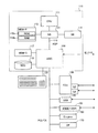
図1は、本発明の実施の形態にかかる画像形成装置の構成を示す説明図である。この図において、自動原稿送り装置(以下、ADFと記述する)1にある、原稿台2に原稿の画像面を上にして置かれた原稿束は、操作部30上のプリントキー34が押下されると、一番下の原稿から給送ローラ3、給送ベルト4によってコンタクトガラス6上の所定の位置に給送される。一枚の原稿を給送完了により原稿枚数をカウントアップするカウント機能を有している。給送された原稿は読み取りユニット50によってコンタクトガラス6上の原稿の画像データを読み取り後、読み取りが終了した原稿は、給送ベルト4および排送ローラ5によって排出される。さらに、原稿セット検知7にて原稿台2につぎの原稿が有ることを検知した場合、前原稿と同様にコンタクトガラス6上に給送される。給送ローラ3、給送ベルト4、排送ローラ5は搬送モータ26によって駆動される。第1トレイ8、第2トレイ9、第3トレイ10に積載された記録紙は、それぞれ第1給紙装置11、第2給紙装置12、第3給紙装置13によって給紙され、縦搬送ユニット14によって感光体ドラム15に当接する位置まで搬送される。読み取りユニット50にて読み込まれた画像データは、書き込みユニット57からのレーザによって感光体ドラム15に書き込まれ、現像ユニット27を通過することによってトナー像が形成される。そして、記録紙は感光体ドラム15の回転と等速で搬送ベルト16によって搬送されながら、感光体ドラム15上のトナー像が転写される。その後、定着ユニット17にて画像を定着させ、排紙ユニット18によって後処理装置のフィニシャ70に排出される。
(Embodiment)
FIG. 1 is an explanatory diagram showing a configuration of an image forming apparatus according to an embodiment of the present invention. In this figure, for a document bundle placed on the document table 2 with the image surface of the document on the document table 2 in the automatic document feeder (hereinafter referred to as ADF) 1, the print key 34 on the operation unit 30 is pressed. Then, the lowermost document is fed to a predetermined position on the
後処理装置のフィニシャ70は、本体の排紙ローラ19によって搬送された記録紙を、通常、排紙ローラ72への方向と、ステープル処理部への方向へ導くことができる。切り替え板71を上に切り替えることにより、搬送ローラ73を経由して通常排紙トレイ74側に排紙することができる。また、切り替え板71を下方向に切り替えることで、搬送ローラ75、77を経由して、ステープル台78に搬送することができる。ステープル台78に積載された記録紙は、一枚排紙されるごとに紙揃え用のジョガー79によって、紙端面が揃えられ、一部のコピー完了と共にステープラ76によって綴じられる。ステープラ76で綴じられた記録紙群は自重によって、ステープル完了排紙トレイ80に収納される。一方、通常の排紙トレイ74は前後に移動可能な排紙トレイである。前後に移動可能な排紙トレイ部74は、原稿毎、あるいは画像メモリによってソーティングされたコピー部毎に、前後に移動し、簡易的に排出されてくるコピー紙を仕分けるものである。
The
記録紙の両面に画像を作像する場合は、各給紙トレイ8〜10から給紙され作像された記録紙を排紙トレイ74側に導かないで、経路切り替えのための分岐爪を上側にセットすることで、一旦、両面給紙ユニット91にストックする。その後、両面給紙ユニット91にストックされた記録紙は再び感光体ドラム15に作像されたトナー画像を転写するために、両面給紙ユニット91から再給紙され、経路切り替えのための分岐爪を下側にセットし、排紙トレイ74に導く。このように記録紙の両面に画像を作成する場合に両面給紙ユニット91は使用される。また、画像の載った記録紙の裏面に印字を行う際にも両面給紙ユニット91を用いて記録紙の裏表を変える。感光体ドラム15、搬送ベルト16、定着ユニット17、排紙ユニット18、現像ユニット27はメインモータによって駆動され、各給紙装置11〜13はメインモータ25の駆動を各々給紙クラッチによって伝達駆動される。縦搬送ユニット14はメインモータの駆動を中間クラッチによって伝達駆動される。
When forming an image on both sides of the recording paper, the recording paper fed from each of the paper feed trays 8 to 10 is not guided to the
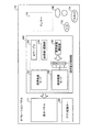
図2は、かかる複合機200のハードウェア構成を示すブロック図である。この図に示すように、この複合機200は、コントローラ110とエンジン部(Engine)160とPCI(Peripheral Component Interconnect)バスで接続した構成となる。コントローラ110は、複合機200全体の制御と描画、通信、OP(Operation Panel)170からの入力を制御するコントローラである。エンジン部60は、PCIバスに接続可能なプリンタエンジンなどであり、たとえば白黒プロッタ、1ドラムカラープロッタ、4ドラムカラープリンタ、スキャナまたはファックスユニットなどである。なお、このエンジン部60には、プロッタなどのいわゆるエンジン部分に加えて、誤差拡散やガンマ変換などの画像処理部分が含まれる。
FIG. 2 is a block diagram showing a hardware configuration of the
コントローラ110は、CPU111と、ノースブリッジ(NB)113と、システムメモリ(MEM−P)112と、サウスブリッジ(SB)114と、ローカルメモリ(MEM−C)117と、ASIC(Application Specific Intergrated Circuit)116と、ハードディスクドライブ(HDD)118とを有し、ノースブリッジ(NB))113とASIC116との間をAGP(Accelerated Graphics Port)バス115とで接続した構成となる。また、MEM−P112は、ROM(Read Only Memory)112aと、RAM(Random Access Memory)112bとをさらに有する。
The
CPU111は、複合機200の全体制御をおこなうものである。NE113、MEM−P112およびSB114からなるチップセットを有し、このチップセットを介して他の機器と接続される。
The
NB113は、CPU111とMEM−P112、SB114、AGP115とを接続するためのブリッジであり、MEP−P12に対する読み書きなどを制御するメモリコントローラと、PCIマスタおよびAGPターゲットとを有する。
The
MEM−P112は、プログラムやデータの格納用メモリ、プログラムやデータの展開用メモリ、プリンタの描画用メモリなどとして用いるシステムメモリである、ROM112aとRAM112bとからなる。ROM112aは、プログラムやデータの格納用メモリとして用いる読み出し専用のメモリであり、RAM112bは、プログラムやデータの展開用メモリ、プリンタの描画用メモリなどとして用いる書き込みおよび読み出し可能なメモリである。
The MEM-
SB114は、NB113とPCIデバイス、周辺デバイスとを接続するためのブリッジである。このSB114は、PCIバスを介してNB113と接続されており、このPCIバスには、ネットワークインターフェース(I/F)部なども接続される。
The
ASIC116は、画像処理用のハードウェア要素を有する画像処理用途向けのIC(Integrated Circuit)であり、AGP115、PCIバス、HDD118およびMEM−C117をそれぞれ接続するブリッジの役割を有する。このASIC116は、PCIターゲットおよびAGPマスタと、ASIC16の中核をなすアービタ(ARB)と、MEM−C117を制御するメモリコントローラと、ハードウェアロジックなどにより画像データの回転などを行う複数のDMAC(Direct Memory Controller)と、エンジン部60との間でPCIバスを介したデータ転送を行うPCIユニットからなる。このASIC1116には、PCIバスを介してFCU(Fax Control Unit)130、USB(Universal Serial Bus)140、IEEE1394(the Instiute of Electrical and Electronics Engineers 1394)インターフェース150が接続される。
The
MEM−C117は、コピー用画像バッファ、符号バッファとして用いるローカルメモリであり、HDD(Hard Disk Drive)118は、画像データの蓄積、プログラムの蓄積、フォントデータの蓄積、フォームの蓄積を行うためのストレージである。
The MEM-
AGP115は、グラフィックス処理を高速化するために提案されたグラフィックスアクセレーターカード用のバスインターフェースであり、MEM−P112に高スループットで直接アクセスすることにより、グラフィックスアクセレーターカードを高速にするものである。
The
図3は、本発明の実施の形態にかかるオペレーションパネルの構成を示すブロック図であり、図4は、その構成例を示す説明図である。図3において、このオペレーションパネル170は、表示パネル171、テンキー172、クリア/ストップキー173、スタートキー174、画面切替キー180、アプリ切替キー185、操作表示制御部190などを備えている。
FIG. 3 is a block diagram showing a configuration of the operation panel according to the embodiment of the present invention, and FIG. 4 is an explanatory diagram showing a configuration example thereof. 3, the
操作表示制御部190は、コピー、ファクシミリ、スキャナ機能の複数の機能に対応するそれぞれの標準画面(たとえば、図5の191a参照)を表示する標準画面モード191、後述する簡単画面(たとえば、図9の192a参照)を表示する簡単画面モード192、ユーザコード毎にユーザを登録し認識するためのIDテーブル193、IDテーブル193にユーザ登録や認証を行うID登録/認識部194、表示画面の表示時間を、たとえば機能毎およびユーザ毎に測定する表示時間測定部195を備えている。表示時間測定部195は、図示のA,B,C,D,・・というように機能毎およびユーザ毎の表示画面の使用頻度あるいは使用時間を測定する。
The operation
なお、図3に示すブロック図では、オペレーションパネル170の制御を操作表示制御部190が行うようにしているが、このオペレーションパネル170の制御を後述する図7のCPU68によって行ってもよい。また、ハードウェア構成のみでなくソフトウェアによって表示制御を行なってもよい。
In the block diagram shown in FIG. 3, the operation
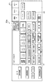
図4において、オペレーションパネル170には、表示パネル(液晶タッチパネル)171、テンキー172、クリア/ストップキー173、スタートキー174、予熱キー175、リセットキー176、初期設定キー177があり、表示パネル(液晶タッチパネル)171には、各種機能キーおよび画像形成装置の状態を示すメッセージなどが表示される。
4, the
オペレータが液晶タッチである表示パネル171に表示されたキーにタッチすることで、選択された機能を示すキーが黒く反転する。また、機能の詳細を指定しなければならない場合(たとえばページ印字の種類等)はキーにタッチすることで詳細機能の設定画面が表示される。このように、液晶タッチパネルは、ドット表示器を使用しているため、そのときの最適な表示をグラフィカルに行うことが可能である。
When the operator touches a key displayed on the
初期設定キー177を押すことで、機械の初期状態を任意にカスタマイズすることが可能である。機械が収納している用紙サイズを設定したり、コピー機能のリセットキーを押したときに設定される状態を任意に設定することが可能である。また、一定時間操作がないときに優先して選択されるアプリケーション等も選択すること、国際エネルギースター計画にしたがった低電力への移行時間の設定や、オートオフ/スリープモードへの移行する時間を設定することが可能である。予熱キー175を押すと、機械は待機状態から、電力低減状態に移行し、定着温度を低下させたり、オペレーションパネル170の表示を消灯する。予熱状態は、国際エネルギースター計画でいう、低電力状態を意味している。また、予熱状態、オフ状態/スリープ状態を解除し、待機状態に移行させるには、この予熱キーを再度押下する。
By pressing the
コピーキー178の押下により、コピー機能の使用が可能である。コピーサーバーキー179は、既存の蓄積画像データの編集(コピーモード設定、印刷、削除)を行なうときに使用する。コピーサーバーの詳細については、後述する。また、スキャナアプリキー1811は原稿を機器内部の記憶装置に蓄積するとき、スキャナより読み取った入力画像や蓄積されている画像データなどを外部に送信するときなどに使用する。この詳細は後述する。
By pressing the
図5は、図4における表示パネル171の表示一例を示す説明図である。オペレータが表示パネル171に表示されたキーにタッチすることで、選択された機能を示すキーが黒く反転する。また、機能の詳細を指定しなければならない場合(たとえば変倍であれば変倍値等)は、キーにタッチすることで、詳細機能の設定画面が表示される。このように、液晶タッチパネルは、ドット表示器を使用しているため、そのときの最適な表示をグラフィカルに行なうことが可能である。
FIG. 5 is an explanatory diagram showing an example of display on the
図5において左上は、「コピーできます」、「お待ちください」などのメッセージを表示するメッセージエリア、その右は、セットした枚数を表示するコピー枚数表示部、記録紙を自動的に選択する自動用紙選択キー、コピーを一部ずつページ順にそろえる処理を指定するソートキー、コピーをページ毎に仕分けする処理を指定するスタックキー、ソート処理されたものを一部ずつ綴じる処理を指定するステープルキー、倍率を等倍にセットする等倍キー、拡大/縮小倍率をセットする変倍キー、両面モードを設定する両面キー、とじ代モード等を設定する編集キー、表紙/合紙モードを設定する表紙/合紙キー、デジタル複写機のネットワークを介して多量のプリント動作を複数に分けてプリントアウトする連結モードキーである。また、給紙トレイ数に対応した給紙トレイ状態を示し、手動で給紙段を設定するためのキーが給紙段分表示されている。 In FIG. 5, the upper left is a message area for displaying messages such as “Ready to copy” and “Please wait”, the right is a copy number display section for displaying the set number of sheets, and an automatic sheet for automatically selecting a recording sheet Select key, sort key that specifies processing to arrange copies in order of pages, stack key that specifies processing to sort copies by page, staple key that specifies processing to bind sorted items partly, and magnification Same size key to set the same size, Scaling key to set the enlargement / reduction ratio, Double side key to set the duplex mode, Edit key to set the binding margin mode, etc. Cover page / Slip sheet to set the cover / interleaf mode This is a connection mode key that prints out a large number of printing operations divided into a plurality of parts via a network of keys and digital copying machines. In addition, a paper feed tray state corresponding to the number of paper feed trays is displayed, and keys for manually setting the paper feed tray are displayed for the number of paper feed trays.
図6は、メインコントローラを中心に、制御装置を図示したものである。メインコントローラ201は画像形成装置全体を制御する。メインコントローラ201には、オペレータに対する表示、オペレータからの機能設定入力制御を行うオペレーションパネル170、スキャナの制御、原稿画像を画像メモリーに書き込む制御、画像メモリからの作像を行う制御等を行う画像処理ユニット(IPU)202、原稿自動送り装置(ADF)1、などの分散制御装置が接続されている。各分散制御装置とメインコントローラ201は必要に応じて機械の状態、動作司令のやりとりを行っている。また、紙搬送等に必要なメインモータ、各種クラッチも接続されている。
FIG. 6 illustrates the control device with the main controller as the center. The
図1に戻り、画像形成装置の原稿読み取りから、画像の書き込みまでを説明する。読み取りユニット50は、原稿を載置するコンタクトガラス6と光学走査系で構成されており、光学走査系には、露光ランプ51、第1ミラー52、レンズ53、CCDイメージセンサ54等々で構成されている。露光ランプ51及び第1ミラー52は図示しない第1キャリッジ上に固定され、第2ミラー55および第3ミラー56は図示しない第1キャリッジ上に固定されている。原稿像を読み取るときには、光路長が変わらないように、第1キャリッジ第2キャリッジとが2対1の相対速度で機械的に走査される。この光学走査系は、図示しないスキャナ駆動モータにて駆動される。原稿画像は、CCDイメージセンサ54によって読み取られ、電気信号に変換されて処理される。書き込みユニット57はレーザ出力ユニット58、結像レンズ59、ミラー60で構成され、レーザ出力ユニット58の内部には、レーザ光源であるレーザダイオードおよびモータによって高速で定速回転する多角形ミラー(ポリゴンミラー)が備わっている。書き込みユニット57から出力されるレーザ光が、画像作像系の感光体ドラム15に照射される。図示しないが感光体ドラム15の一端近傍のレーザビームを照射される位置に、主走査同期信号を発生するビームセンサが配置されている。
Returning to FIG. 1, a process from reading an original of the image forming apparatus to writing an image will be described. The
図7は、画像処理ユニット(IPU)202の内部構成を示すブロック図である。露光ランプ51から照射された光の反射を、CCDイメージセンサ54にて光電変換し、A/Dコンバータ61にてデジタル信号に変換する。デジタル信号に変換された画像信号は、シェーディング補正62がなされた後、画像処理部63にてMTF補正、ガンマ補正等がなされる。その後、印字合成部81を介して入力した画像データを変倍回路85へ、あるいは、メモリーコントローラ65へ切り替えて供給するものであり、変倍回路82を経由した画像信号は変倍率に合せて拡大/縮小され、書き込みユニット57に送られる。
FIG. 7 is a block diagram showing an internal configuration of the image processing unit (IPU) 202. The reflection of light emitted from the
一方、メモリーコントローラ65とセレクタ64間は、双方向に画像信号を入出力可能な構成となっている。図7には特に明示していないが、IPU202には読み取りユニット50から入力される画像データ以外にもI/Oポート67を介して外部から供給される画像データ、たとえばパーソナルコンピュータ等のデータ処理装置から入力したデータも処理できるよう、複数のデータの入出力の選択を行なう機能を有しているものとする。
On the other hand, the
また、メモリーコントローラ65などへの設定や、読み取りユニット50および書き込みユニット57の制御を行うCPU68、およびそのプログラムやデータを格納するROM69、RAM82、NV−RAM83を備えている。さらにCPU68は、メモリーコントローラ65を介して、画像メモリー66のデータの書き込み、読み出しが行える。原稿画像でメモリーコントローラ65へ送られた画像は、メモリーコントローラ65内にある画像圧縮装置によって画像データを圧縮した後、画像メモリー66に送られる。ここで画像圧縮する理由は、最大画像サイズ分の256階調のデータをそのまま画像メモリー66に書き込むことも可能であるが、1枚の原稿画像で画像メモリ−66を大変多く使用する。画像圧縮を行うことで、限られた画像メモリを有効に利用できる。また、一度に多くの原稿画像データを記憶することができるため、ソート機能として、貯えられた原稿画像イメージデータをページ順に出力することができる。この場合、画像を出力する際に画像メモリー66のデータをメモリーコントローラ65内の伸長装置で順次伸長しながら出力を行う。このような機能は一般に「電子ソート」と呼ばれている。
Further, a
また、画像メモリ−66の機能を利用して、複数枚の原稿画像を、画像メモリの記録紙一枚分のエリアを分割したエリアに順次読み込むことも可能となる。たとえば4枚の原稿画像を、画像メモリの記録紙一枚分の4等分されたエリアに順次書き込むことで、4枚の原稿が一枚の記録紙イメージに合成され集約されたコピー出力を得ることが可能となる。このような機能は一般に「集約コピー」と呼ばれている。
In addition, by using the function of the
画像メモリー66の画像はCPU68からアクセス可能な構成となっている。このため画像メモリの内容を加工することが可能であり、たとえば画像の間引き処理、画像の切り出し処理等が行える。加工には、メモリーコントローラ65のレジスタにデータを書き込むことで画像メモリの処理を行うことができる。加工された画像は再度画像メモリーに保持される。画像メモリー66は、処理を行う画像データの大きさにより複数のエリアに分割して画像データの入出力を同時に実行可能な構成をとっている。各分割したエリアに画像データの入力、出力をそれぞれ並列に実行可能にするためにメモリーコントローラ65とのインターフェイスにリード用とライト用の二組のアドレス・データ線で接続されている。これによりエリア1に画像を入力(ライト)する間にエリア2より画像を出力(リード)するという動作が可能になる。
The image in the
画像メモリー66は、多くの画像データを収納するためハードディスクを別に設けることもある。ハードディスクを用いる事により、外部電源が不用で永久的に画像を保持できる特徴もある。複数の定型の原稿(フォーマット原稿)をスキャナで読み込み保持するためには、このハードディスク84が用いられるのが一般的である。
The
書き込み、読み出しには本体の作像やスキャナからの画像書き込みに対し処理速度の差を吸収するために、画像メモリに一旦記憶され処理される。また、画像記憶装置からのデータを書き込みユニット57に送る際は、画像メモリー66に一旦記憶し、書き込みユニット57に送ることになる。このように画像を記憶する装置の画像メモリ66、HD75、スキャナ画像、書き込みユニットに送る画像の入出力は全てメモリーコントローラ65によって画像パスを決められる。
Writing and reading are temporarily stored in the image memory and processed in order to absorb the difference in processing speed with respect to image formation on the main body and image writing from the scanner. When data from the image storage device is sent to the
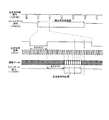
このようにCPU68が画像データの入力、出力を決めることでCPU68に接続されたメモリーコントローラ65が画像の流れを切り替えることが可能となる。ここで、図8を用いて、セレクタ64における1ページ分の画像信号について説明する。/FGATEは、1ページの画像データの副走査方向の有効期間を表している。/LSYNCは、1ライン毎の主走査同期信号であり、この信号が立ち上がった後の所定クロックで、画像信号が有効となる。主走査方向の画像信号が有効であることを示す信号が、/LGATEである。これらの信号は、画素クロックVCLKに同期しており、VCLKの1周期に対し1画素8ビット(256階調)のデータが送られてくる。この実施の形態では、転写紙への書込密度400dpi、最大画素数は、主走査4800画素、副走査6800画素である。またこの実施の形態では、画像データは255に近いほど白画像になるとする。
As described above, the
なお、印字機能は図7に示すように、画像メモリー66の後段で行ない(印字合成部81)転写紙毎に印字を付加する。 As shown in FIG. 7, the printing function is performed after the image memory 66 (print composition unit 81), and printing is added to each transfer sheet.
つぎに、図5に示す標準画面191aと図9に示す簡単画面192aとの切り替え処理について説明する。なお、この実施の形態における標準画面と簡単画面は一例であり、これに限るものではない。管理者によって、機器を利用するユーザ登録を行う際、ユーザコードを設定した後、起動時に利用する機能を選択し、また簡単画面または標準画面のいずれか一方の表示画面を初期画面として設定し、さらに標準画面の使用可否を設定する。なお、認証モードを設定した後は、電源が遮断された後に再び投入されたときに、ユーザコード入力画面(不図示)を表示する。また、認証モードの設定中は設定されているユーザコードと一致するユーザコードが入力されない限り、この複合機200を使用することができない。管理者によって、ユーザに対して使用させる機能を限定させるために標準画面を使用させないようにする場合には、初期設定などでユーザ情報に使用可能な画面情報を設定する。
Next, switching processing between the
ここで、ユーザ毎の起動時に利用する画面については上記のように、ユーザ登録時に確定してもよいし、電源OFF時にユーザが標準画面と簡単画面のどちらの画面を使用していたかをユーザ情報に記録してもよい。 Here, as described above, the screen to be used at startup for each user may be determined at the time of user registration, and user information indicating whether the user is using the standard screen or the simple screen when the power is turned off. May be recorded.
電源ON時には、ユーザ認証の設定が有効になっている場合は、ユーザ認証を行い、登録済みのユーザ情報が入力された場合に、ユーザ識別子と使用する機能の組み合わせから標準画面と簡単画面の中から表示する画面を決定する。また、オペレーションパネル170の画面切替キー180を押下することで簡単画面と、標準画面との切り替えを行う。画面切替キー180押下時には、現在の利用機能での標準画面の利用権限をチェックし利用可能の場合のみ、標準画面への移行を行う。
When the user authentication setting is enabled when the power is turned on, the user authentication is performed, and when the registered user information is input, the combination of the user identifier and the function to be used is selected from the standard screen and the simple screen. Determine the screen to display. In addition, a simple screen and a standard screen are switched by pressing a
図10はこの複合機200の制御部(CPU68)による認証モード設定時の初期画面表示処理の一例を示すフローチャートである。このルーチンは、認証モードの設定時にユーザコードが入力されたときにメインルーチンからコールされてスタートする。そして、まず入力されたユーザコードが設定されている各ユーザコードのいずれかと一致するか否かを判断する(ステップS11)。ここで、一致しなければそのままメインルーチンへリターンするが、一致した場合にはこの複合機200の使用を許可し、そのユーザコードに対して最初に起動する機能(コピー、ファクシミリ、スキャナ等)を決定する(ステップS12)。続いて、そのユーザコードに対して設定された表示画面が簡単画面か否かを判断し(ステップS13)、簡単画面であればそれを表示し(ステップS14)、一方、簡単画面でなく標準画面であればそれを、それぞれ初期画面として表示パネル171に表示する(ステップS15)。
FIG. 10 is a flowchart showing an example of the initial screen display process when the authentication mode is set by the control unit (CPU 68) of the
このように、利用機能と各ユーザコードとその各ユーザコード毎に簡単画面または標準画面のいずれか一方の表示画面を設定しておき、その各ユーザコードのいずれかと一致するユーザコードが入力された場合にのみこの複合機200の使用を許可し、そのユーザコードに対して設定された表示画面を初期画面として表示パネル171に表示すれば、各ユーザによる表示画面の切り換え操作を省くこともでき、操作性が向上する。ここで、認証モードOFFの場合はユーザの認証操作は行わないが、内部的にゲストユーザとしてユーザ情報を保持することで、認証モードONの場合と同様のシーケンスでデフォルトの設定画面を表示することが可能である。
As described above, either the simple screen or the standard screen is set for each use function, each user code, and each user code, and a user code that matches one of the user codes is input. If the use of the
図11は、この複合機200の制御部(CPU68)による認証モード設定時の画面切換処理の一例を示すフローチャートである。このルーチンは、認証モード設定時に表示パネル171に初期画面が表示された後、画面切換キー180が押下された場合にメインルーチンからコールされてスタートし、まず表示パネル171上の現在の表示画面が簡単画面であるか標準画面の設定であるかを否かを判断する(ステップS21)。
FIG. 11 is a flowchart illustrating an example of a screen switching process when the authentication mode is set by the control unit (CPU 68) of the
続いて、表示パネル171上の現在の表示画面が標準画面であれば、それを簡単画面に切り換えてメインルーチンへリターンする(ステップS24)。一方、ステップS21において、簡単画面であれば入力されたユーザコードと現在使用している機能に対して標準画面が使用可と設定されているか否かを判断する(ステップS22)。ここで、使用可ではなく使用不可と設定されていれば、表示画面を簡単画面から標準画面への切り換えを禁止し、使用可と設定されていれば表示パネル171上の表示画面を簡単画面から標準画面に切り換え(ステップS23)、この後、メインルーチンへリターンする。
Subsequently, if the current display screen on the
このように、上記各ユーザコード毎に標準画面の使用可否も設定しておき、認証モード設定時に表示パネル171に初期画面を表示した後、上記入力されたユーザコードに対して標準画面が使用不可と設定されている場合には、簡単画面から標準画面への切り換えを禁止するようにすれば、ユーザ毎の差別化を図ることもできる。
As described above, whether or not the standard screen can be used is set for each user code, and after the initial screen is displayed on the
また、図12はアプリ機能切り替え時の画面表示処理の一例を示すフローチャートである。このルーチンは認証モード設定時にアプリキー切替キー185が押下された場合にメインルーチンからコールされてスタートし、まず、押下されたキーごとに割り当てられた機能に対して、現在のユーザが移行先の機能に対して簡単画面と標準画面のどちらを表示するかを判断し(ステップS31)、適切な画面を表示する(ステップS32、S33)。ここで、認証モードOFFの場合にも、内部的にゲストユーザとしてユーザ情報を保持することで、認証モードONの場合と同様のシーケンスであらかじめ設定された画面を表示することが可能である。 FIG. 12 is a flowchart illustrating an example of a screen display process when switching between application functions. This routine is started by calling from the main routine when the application key switching key 185 is pressed when setting the authentication mode. First, for the function assigned to each pressed key, the current user is the destination of migration. It is determined whether a simple screen or a standard screen is displayed for the function (step S31), and an appropriate screen is displayed (steps S32 and S33). Here, even when the authentication mode is OFF, it is possible to display a preset screen in the same sequence as when the authentication mode is ON by internally storing user information as a guest user.
図10〜12のルーチンは各機能毎にプログラムの実行手段を有しており、標準画面と簡単画面の設定内容を保持する記録媒体も各機能毎に割り当てることで、機能毎の画面切り替えと機能毎の表示画面状態の保持を実現する。なお、上記の図10〜図12の制御は制御部(CPU68)によって実行する例について示したが、この他に図3に示す操作表示制御部190によって実行することもできる。
The routines shown in FIGS. 10 to 12 have program execution means for each function, and a recording medium that holds the setting contents of the standard screen and the simple screen is also assigned to each function, so that screen switching and function for each function are performed. Realization of the display screen state for each time. Although the above-described control of FIGS. 10 to 12 is shown as an example executed by the control unit (CPU 68), it can also be executed by the operation
つぎに、簡単画面と標準画面の表示した累計時間を計測し、使用した時間の長い方の画面を初期画面とする処理について図7の制御部によって実行する例をとって述べる。 Next, the process of measuring the accumulated time displayed on the simple screen and the standard screen and setting the screen with the longer used time as the initial screen will be described with reference to an example executed by the control unit of FIG.
画像形成装置(図1参照)が電源投入により起動されると、初期設定が実行されてイニシャル画面が図4の表示パネル171に表示される。この場合、イニシャル画面は図5の標準画面と図9の簡単画面とのいずれか一方であり、これらの画面の表示時間変数が図7のNV−RAM83に格納されているので、CPU68がNV−RAM83から標準画面と簡単画面に対応する表示累計時間変数を読み出して比較し、これが多い画面が表示パネル171に表示される。このような構成において、ユーザが標準画面と簡単画面のいずれかを利用すると、表示を開始した時点から、表示している画面に対応する表示時間変数が時刻と共に加算される。ユーザが電源OFF、標準画面と簡単画面の表示切替えを行った時点で、これがCPU68によりNV−RAM83に上書きされる。標準画面と簡単画面の表示時間を保持するメモリ領域をコピー、ファクシミリ、スキャナなどの機能毎に配置し、別々に管理することで機能毎に標準画面と簡単画面とのいずれかを初期画面として利用するかを決定することができる。このように画面毎の表示時間変数がNV−RAM83に蓄積された状態で、図1の画像形成装置の動作がオートOFFや手動OFFにより停止されてから電源投入により起動されると、起動される機能と過去に利用した標準画面と簡単画面の表示時間変数が多い画面が図4の表示パネル171にイニシャル画面として表示される。
When the image forming apparatus (see FIG. 1) is started by turning on the power, initial setting is executed and an initial screen is displayed on the
このような作業を繰り返すうち、標準画面と簡単画面との使用時間がCPU68とNV−RAM83により測定(積算)され、標準画面と簡単画面とのうち積算された使用時間が多い方が起動時にタッチパネルに表示される。つまり、ユーザが簡単画面を頻繁に使用する場合には、タッチパネルのイニシャル画面として簡単画面が自動的に表示され、ユーザが標準画面を頻繁に使用する場合には、タッチパネルのイニシャル画面として標準画面が自動的に表示される。
While such work is repeated, the usage time of the standard screen and the simple screen is measured (integrated) by the
なお、この制御は図3に示す操作表示制御部190によって実行することもできる。すなわち、表示時間測定部195によって標準画面と簡単画面との使用時間を測定し、そのうちの使用時間の多い画面をイニシャル画面として表示する。
This control can also be executed by the operation
ところで、これまで説明してきた操作画面表示方法(動作)を、プログラム化し、コンピュータ読み取り可能な記録媒体に記録し、コンピュータ上で実行することもできる。また、操作画面表示方法の一部をネットワーク上に有し、通信回線を通して実現することもできる。 By the way, the operation screen display method (operation) described so far can be programmed, recorded on a computer-readable recording medium, and executed on the computer. Also, a part of the operation screen display method can be provided on the network and realized through a communication line.
すなわち、この実施の形態で説明した操作画面表示方法は、図13に示すように、あらかじめ用意されたプログラムをパーソナルコンピュータやワークステーションなどのコンピュータ(CPU230)で実行することにより実現される。このプログラムは、キーボード235の操作などにより、メモリ231、ハードディスク234、フレキシブルディスク237、CD−ROM(Compact−Disc Read Only Memory)236、MO(Magneto Optical)、DVD(Digital Versatile Disc)などのコンピュータで読み取り可能な記録媒体に記録され、コンピュータ(CPU30)によって記録媒体から読み出し、必要に応じて表示装置233に表示することによって実行される。また、必要に応じてこの画像処理方法のデータを通信装置232から外部装置に送受信することも可能である。
That is, the operation screen display method described in this embodiment is realized by executing a program prepared in advance on a computer (CPU 230) such as a personal computer or a workstation as shown in FIG. This program is executed by a computer such as a
また、このプログラムは、図14に示すように、上記記録媒体を介して、インターネット240などのネットワークによってパーソナルコンピュータなどの装置241〜243に配布することができる。
Further, as shown in FIG. 14, the program can be distributed to
すなわち、このプログラムは、たとえばコンピュータに内蔵されている記録媒体としてのハードディスクに、あらかじめインストールした状態で提供することができる。プログラムは記録媒体に一時的あるいは永続的に格納し、コンピュータにユニットとして組み込んだり、あるいは着脱式の記録媒体として利用することで、パッケージソフトウェアとして提供することができる。 That is, this program can be provided in a state of being installed in advance on a hard disk as a recording medium built in the computer, for example. The program can be temporarily or permanently stored in a recording medium, and can be provided as packaged software by being incorporated in a computer as a unit or being used as a removable recording medium.
記録媒体としては、たとえば、フレキシブルディスク、CD−ROM、MOディスク、DVD、磁気ディスク、半導体メモリなどが利用できる。 As the recording medium, for example, a flexible disk, a CD-ROM, an MO disk, a DVD, a magnetic disk, a semiconductor memory, and the like can be used.
プログラムは、ダウンロードサイトから、LAN(Local Area Network)やインターネットといったネットワークを介して、有線または無線でコンピュータに転送し、そのコンピュータにおいて、内蔵するハードディスクなどの記憶装置にダウンロードさせるようにすることができる。 The program can be transferred from a download site to a computer wired or wirelessly via a network such as a LAN (Local Area Network) or the Internet, and downloaded to a storage device such as a built-in hard disk in the computer. .
したがって、以上説明してきた実施の形態によれば、画像形成装置(複合機200)が提供するコピー、ファクシミリ、スキャナ機能などの機能を選択するとに、機能毎に標準画面と簡単画面の中から予め設定されている画面を表示することで、ユーザの意図する画像形成内容やユーザの習熟度に適した設定表示画面を提供することが可能となる。たとえば、コピー機能は詳細設定を意識した設定を行うが、ファクシミリは基本動作の利用で充分であるといったように、ユーザの熟練度や利用目的は機器単位ではなく、機器が提供する機能毎に存在することが考えられる。これによりユーザにとって不慣れな機能や、簡単画面で表示される基本機能で充分利用目的を果たしている場合に、必要のない設定項目をユーザに見せずに済み、操作性を向上させることが可能になる。 Therefore, according to the embodiment described above, when a function such as a copy function, a facsimile function, and a scanner function provided by the image forming apparatus (multifunction apparatus 200) is selected, a standard screen and a simple screen are previously selected for each function. By displaying the set screen, it is possible to provide a setting display screen suitable for the image formation content intended by the user and the user's proficiency level. For example, the copy function is set with detailed settings in mind, but the use of basic operations is sufficient for facsimile, so the user's skill level and purpose of use exist not for each device but for each function provided by the device. It is possible to do. As a result, when functions that are unfamiliar to the user or basic functions displayed on a simple screen are sufficient for the purpose of use, unnecessary setting items need not be shown to the user, and operability can be improved. .
また、画像形成装置(複合機200)が提供するコピー、ファクシミリ、スキャナ機能などの機能を選択するときに、たとえば標準画面191aと簡単画面192aの中から、ユーザ毎に設定されている画面を表示することで、画像形成内容やユーザ毎の習熟度に適した機能の設定が行なえる。また、入力されたユーザコードに対して標準画面が使用不可と設定されている場合には、簡単画面から標準画面への切り換えを禁止するようにすれば、提供する機能毎にユーザ毎の使用制限を設けることも可能となる。
Further, when selecting a function such as a copy function, a facsimile function, and a scanner function provided by the image forming apparatus (multifunction apparatus 200), for example, a screen set for each user is displayed from the
機能毎に標準画面と簡単画面から、ユーザが実際に使用した時間が長い方を初期画面とすることで、初期画面を標準画面か簡単画面かをユーザが意識して設定する必要がなくなり、実際にユーザの利用状況を考慮した初期画面を設定することが可能となる。 By using the standard screen and simple screen for each function as the initial screen, the user actually spends a lot of time, making it unnecessary for the user to set whether the initial screen is the standard screen or simple screen. It is possible to set an initial screen in consideration of the usage status of the user.
以上のように、本発明にかかる画像形成装置、画像形成装置の操作画面表示方法、および操作画面表示方法をコンピュータに実行させるプログラムを記録したコンピュータ読み取り可能な記録媒体は、コピー、ファクシミリ、スキャナ機能といった複数の機能を有する複合機などの画像形成装置の操作表示画面の制御に有用であり、特に、標準画面と機能毎、あるいはユーザ毎、使用時間に応じた操作画面を表示する装置、方法、システムなどに適している。 As described above, the image forming apparatus according to the present invention, the operation screen display method of the image forming apparatus, and the computer-readable recording medium on which the program for causing the computer to execute the operation screen display method is recorded is a copy, facsimile, and scanner function. It is useful for controlling an operation display screen of an image forming apparatus such as a multi-function machine having a plurality of functions, in particular, an apparatus, a method, and a method for displaying an operation screen corresponding to a standard screen and each function or each user and usage time. Suitable for systems etc.
170 オペレーションパネル
171 表示パネル
180 画面切換キー
185 アプリ切換キー
190 操作表示制御部
193 IDテーブル
194 ID登録/認識部
195 表示時間測定部
200 複合機
170
Claims (7)
起動時に前記機能毎に標準画面と簡単画面のうちいずれかを表示させるかを判断し、前記標準画面と前記簡単画面とを切り換えて表示させる操作表示制御手段を備えたことを特徴とする画像形成装置。 At least in an image forming apparatus having a plurality of functions of copy, facsimile, and scanner functions.
Image formation comprising operation display control means for determining whether to display a standard screen or a simple screen for each function at startup and switching between the standard screen and the simple screen apparatus.
ユーザを識別するためのユーザコードを設定するユーザコード設定手段と、
設定されたユーザコード毎に、そのユーザが選択した機能毎に前記簡単画面または前記標準画面のいずれか一方の表示画面を設定する画面設定手段と、
を備えたことを特徴とする請求項1に記載の画像形成装置。 further,
User code setting means for setting a user code for identifying the user;
Screen setting means for setting either the simple screen or the standard screen for each function selected by the user for each set user code;
The image forming apparatus according to claim 1, further comprising:
前記操作表示制御手段は、前記標準画面と前記簡単画面の中から表示累計時間に応じて、機能毎に前記簡単画面または前記標準画面のいずれか一方の表示画面を設定することを特徴とする請求項1または2に記載の画像形成装置。 Furthermore, a display time measuring means for measuring the accumulated time displayed for each of the standard screen and the simple screen is provided,
The operation display control unit sets one of the simple screen and the standard screen for each function according to a display accumulated time from the standard screen and the simple screen. Item 3. The image forming apparatus according to Item 1 or 2.
起動時に前記機能毎に前記標準画面と前記簡単画面のうちいずれかを表示させるかを判断し、この判断した画面に切り換えて表示する画面表示工程を含むことを特徴とする画像形成装置の操作画面表示方法。 An operation screen display method for an image forming apparatus having at least a plurality of functions of copy, facsimile, and scanner functions,
An operation screen for an image forming apparatus, comprising: a screen display step for determining whether to display either the standard screen or the simple screen for each function at startup and switching to the determined screen Display method.
ユーザコードを認識するユーザコード認識工程と、
前記認識されたユーザコードに設定されているデフォルトのアプリケーションを決定するアプリケーション決定工程と、
前記アプリケーションの初期画面が標準画面か簡単画面であるかを判断する表示画面判断工程と、
を含むことを特徴とする請求項4に記載の画像形成装置の操作画面表示方法。 further,
A user code recognition process for recognizing the user code;
An application determining step for determining a default application set in the recognized user code;
A display screen determining step for determining whether the initial screen of the application is a standard screen or a simple screen;
The operation screen display method for an image forming apparatus according to claim 4, further comprising:
前記画面表示工程は、前記標準画面と前記簡単画面の中から前記表示時間測定工程の表示累計時間結果にしたがって、機能毎に前記簡単画面または前記標準画面のいずれか一方の表示画面を設定し表示することを特徴とする請求項4または5に記載の画像形成装置の操作画面表示方法。 Furthermore, a display time measuring step of measuring a cumulative time displayed for each of the standard screen and the simple screen,
The screen display step sets and displays either the simple screen or the standard screen for each function according to the display accumulated time result of the display time measurement step from the standard screen and the simple screen. 6. The operation screen display method for an image forming apparatus according to claim 4, wherein the operation screen is displayed.
Priority Applications (1)
| Application Number | Priority Date | Filing Date | Title |
|---|---|---|---|
| JP2005256951A JP2007074149A (en) | 2005-09-05 | 2005-09-05 | Image forming apparatus, method for displaying operating image of image forming apparatus, and computer-readable recording medium with recorded program making computer implement method of displaying operating image |
Applications Claiming Priority (1)
| Application Number | Priority Date | Filing Date | Title |
|---|---|---|---|
| JP2005256951A JP2007074149A (en) | 2005-09-05 | 2005-09-05 | Image forming apparatus, method for displaying operating image of image forming apparatus, and computer-readable recording medium with recorded program making computer implement method of displaying operating image |
Publications (2)
| Publication Number | Publication Date |
|---|---|
| JP2007074149A true JP2007074149A (en) | 2007-03-22 |
| JP2007074149A5 JP2007074149A5 (en) | 2008-09-18 |
Family
ID=37935253
Family Applications (1)
| Application Number | Title | Priority Date | Filing Date |
|---|---|---|---|
| JP2005256951A Pending JP2007074149A (en) | 2005-09-05 | 2005-09-05 | Image forming apparatus, method for displaying operating image of image forming apparatus, and computer-readable recording medium with recorded program making computer implement method of displaying operating image |
Country Status (1)
| Country | Link |
|---|---|
| JP (1) | JP2007074149A (en) |
Cited By (5)
| Publication number | Priority date | Publication date | Assignee | Title |
|---|---|---|---|---|
| US20100027055A1 (en) * | 2008-07-30 | 2010-02-04 | Sharp Kabushiki Kaisha | Image forming apparatus and preview display method |
| JP2010268345A (en) * | 2009-05-18 | 2010-11-25 | Sharp Corp | Information processing apparatus processing function-related information, and image forming apparatus including the information processing apparatus or communication apparatus communicable with the information processing apparatus |
| US8482774B2 (en) | 2009-05-18 | 2013-07-09 | Sharp Kabushiki Kaisha | Image forming apparatus displaying function-related information |
| US8526040B2 (en) | 2009-05-18 | 2013-09-03 | Sharp Kabushiki Kaisha | Image forming apparatus comprising an information processing apparatus, a combination storage unit, a selecting unit, and a display unit |
| JP2015228087A (en) * | 2014-05-30 | 2015-12-17 | ブラザー工業株式会社 | Function execution device and display control method |
Citations (13)
| Publication number | Priority date | Publication date | Assignee | Title |
|---|---|---|---|---|
| JPS62200365A (en) * | 1986-02-28 | 1987-09-04 | Ricoh Co Ltd | Image forming device |
| JPH06130766A (en) * | 1992-10-16 | 1994-05-13 | Fuji Xerox Co Ltd | Image processor |
| JPH08307570A (en) * | 1995-03-07 | 1996-11-22 | Ricoh Co Ltd | Image forming device |
| JPH09265248A (en) * | 1996-03-28 | 1997-10-07 | Ricoh Co Ltd | Image forming device |
| JPH09305063A (en) * | 1996-05-14 | 1997-11-28 | Ricoh Co Ltd | Image forming device |
| JPH1049001A (en) * | 1996-08-01 | 1998-02-20 | Ricoh Co Ltd | Image forming device |
| JPH1079819A (en) * | 1996-09-04 | 1998-03-24 | Fuji Xerox Co Ltd | Composite machine |
| JP2000324289A (en) * | 1999-05-12 | 2000-11-24 | Konica Corp | Composite image device |
| JP2005057617A (en) * | 2003-08-06 | 2005-03-03 | Ricoh Co Ltd | Image forming device |
| JP2005074715A (en) * | 2003-08-29 | 2005-03-24 | Kyocera Mita Corp | Image forming apparatus |
| JP2005172948A (en) * | 2003-12-08 | 2005-06-30 | Kyocera Mita Corp | Image forming apparatus |
| JP2007068040A (en) * | 2005-09-01 | 2007-03-15 | Ricoh Co Ltd | Image-forming apparatus |
| JP2007074150A (en) * | 2005-09-05 | 2007-03-22 | Ricoh Co Ltd | Image forming apparatus, method, and program |
-
2005
- 2005-09-05 JP JP2005256951A patent/JP2007074149A/en active Pending
Patent Citations (13)
| Publication number | Priority date | Publication date | Assignee | Title |
|---|---|---|---|---|
| JPS62200365A (en) * | 1986-02-28 | 1987-09-04 | Ricoh Co Ltd | Image forming device |
| JPH06130766A (en) * | 1992-10-16 | 1994-05-13 | Fuji Xerox Co Ltd | Image processor |
| JPH08307570A (en) * | 1995-03-07 | 1996-11-22 | Ricoh Co Ltd | Image forming device |
| JPH09265248A (en) * | 1996-03-28 | 1997-10-07 | Ricoh Co Ltd | Image forming device |
| JPH09305063A (en) * | 1996-05-14 | 1997-11-28 | Ricoh Co Ltd | Image forming device |
| JPH1049001A (en) * | 1996-08-01 | 1998-02-20 | Ricoh Co Ltd | Image forming device |
| JPH1079819A (en) * | 1996-09-04 | 1998-03-24 | Fuji Xerox Co Ltd | Composite machine |
| JP2000324289A (en) * | 1999-05-12 | 2000-11-24 | Konica Corp | Composite image device |
| JP2005057617A (en) * | 2003-08-06 | 2005-03-03 | Ricoh Co Ltd | Image forming device |
| JP2005074715A (en) * | 2003-08-29 | 2005-03-24 | Kyocera Mita Corp | Image forming apparatus |
| JP2005172948A (en) * | 2003-12-08 | 2005-06-30 | Kyocera Mita Corp | Image forming apparatus |
| JP2007068040A (en) * | 2005-09-01 | 2007-03-15 | Ricoh Co Ltd | Image-forming apparatus |
| JP2007074150A (en) * | 2005-09-05 | 2007-03-22 | Ricoh Co Ltd | Image forming apparatus, method, and program |
Cited By (9)
| Publication number | Priority date | Publication date | Assignee | Title |
|---|---|---|---|---|
| US20100027055A1 (en) * | 2008-07-30 | 2010-02-04 | Sharp Kabushiki Kaisha | Image forming apparatus and preview display method |
| JP2010035019A (en) * | 2008-07-30 | 2010-02-12 | Sharp Corp | Image forming apparatus, and preview display method |
| US8559034B2 (en) * | 2008-07-30 | 2013-10-15 | Sharp Kabushiki Kaisha | Image forming apparatus and preview display method |
| JP2010268345A (en) * | 2009-05-18 | 2010-11-25 | Sharp Corp | Information processing apparatus processing function-related information, and image forming apparatus including the information processing apparatus or communication apparatus communicable with the information processing apparatus |
| US8482774B2 (en) | 2009-05-18 | 2013-07-09 | Sharp Kabushiki Kaisha | Image forming apparatus displaying function-related information |
| US8526040B2 (en) | 2009-05-18 | 2013-09-03 | Sharp Kabushiki Kaisha | Image forming apparatus comprising an information processing apparatus, a combination storage unit, a selecting unit, and a display unit |
| US8531688B2 (en) | 2009-05-18 | 2013-09-10 | Sharp Kabushiki Kaisha | Information processing apparatus processing function-related information and image forming apparatus including the information processing apparatus or a communication apparatus communicable with the information processing apparatus |
| JP2015228087A (en) * | 2014-05-30 | 2015-12-17 | ブラザー工業株式会社 | Function execution device and display control method |
| US10013043B2 (en) | 2014-05-30 | 2018-07-03 | Brother Kogyo Kabushiki Kaisha | Function execution apparatus, and method and computer-readable medium for customization of standby screen based on frequency in use |
Similar Documents
| Publication | Publication Date | Title |
|---|---|---|
| JP4093143B2 (en) | Image forming apparatus, program, and computer-readable recording medium | |
| JP2006248672A (en) | Image forming device | |
| EP1753219B1 (en) | Image processing apparatus, image output method, and computer program product | |
| JP2007074149A (en) | Image forming apparatus, method for displaying operating image of image forming apparatus, and computer-readable recording medium with recorded program making computer implement method of displaying operating image | |
| JP2006253973A (en) | Image forming apparatus, image forming method, program and record medium | |
| JP3938844B2 (en) | Image forming system | |
| JP5359422B2 (en) | Image forming apparatus and method of controlling image forming apparatus | |
| JP4796272B2 (en) | Image forming apparatus | |
| JP2004230858A (en) | Image forming apparatus | |
| JP2011109353A (en) | Image processor | |
| JP2004230603A (en) | Image forming apparatus, method of forming image, and program for executing the method on computer | |
| JP4755440B2 (en) | Image forming apparatus, control method, program, and recording medium | |
| JP2007049252A (en) | Image processing apparatus, image output method, program, and recording medium | |
| JP4037997B2 (en) | Image forming apparatus and reserved job replacement method thereof | |
| JP3933402B2 (en) | Network system for image forming apparatus | |
| JP3898069B2 (en) | Image forming apparatus | |
| JP4437739B2 (en) | Image forming apparatus and program | |
| JP4597850B2 (en) | Image reading apparatus and control method thereof | |
| JP4113818B2 (en) | Image forming connection system | |
| JP2007049250A (en) | Image processing apparatus, image output method, program, and recording medium | |
| JP4680759B2 (en) | Image forming apparatus, image forming method, and image forming program | |
| JP2003231322A (en) | Imaging apparatus | |
| JP3838822B2 (en) | Image forming apparatus and image processing apparatus including the image forming apparatus | |
| JP2008022336A (en) | Image forming apparatus, image forming method, and program | |
| JP2005197961A (en) | Image forming/linking system |
Legal Events
| Date | Code | Title | Description |
|---|---|---|---|
| A521 | Written amendment |
Free format text: JAPANESE INTERMEDIATE CODE: A523 Effective date: 20080805 |
|
| A621 | Written request for application examination |
Free format text: JAPANESE INTERMEDIATE CODE: A621 Effective date: 20080805 |
|
| A977 | Report on retrieval |
Free format text: JAPANESE INTERMEDIATE CODE: A971007 Effective date: 20100812 |
|
| A131 | Notification of reasons for refusal |
Free format text: JAPANESE INTERMEDIATE CODE: A131 Effective date: 20100831 |
|
| A521 | Written amendment |
Free format text: JAPANESE INTERMEDIATE CODE: A523 Effective date: 20101028 |
|
| A131 | Notification of reasons for refusal |
Free format text: JAPANESE INTERMEDIATE CODE: A131 Effective date: 20101130 |
|
| A521 | Written amendment |
Free format text: JAPANESE INTERMEDIATE CODE: A523 Effective date: 20110126 |
|
| A02 | Decision of refusal |
Free format text: JAPANESE INTERMEDIATE CODE: A02 Effective date: 20110215 |