JP2007043490A - Camera cradle apparatus and its system - Google Patents
Camera cradle apparatus and its system Download PDFInfo
- Publication number
- JP2007043490A JP2007043490A JP2005225552A JP2005225552A JP2007043490A JP 2007043490 A JP2007043490 A JP 2007043490A JP 2005225552 A JP2005225552 A JP 2005225552A JP 2005225552 A JP2005225552 A JP 2005225552A JP 2007043490 A JP2007043490 A JP 2007043490A
- Authority
- JP
- Japan
- Prior art keywords
- camera
- dsc
- cradle device
- camera cradle
- power button
- Prior art date
- Legal status (The legal status is an assumption and is not a legal conclusion. Google has not performed a legal analysis and makes no representation as to the accuracy of the status listed.)
- Pending
Links
Images


Classifications
-
- H—ELECTRICITY
- H04—ELECTRIC COMMUNICATION TECHNIQUE
- H04N—PICTORIAL COMMUNICATION, e.g. TELEVISION
- H04N1/00—Scanning, transmission or reproduction of documents or the like, e.g. facsimile transmission; Details thereof
- H04N1/00127—Connection or combination of a still picture apparatus with another apparatus, e.g. for storage, processing or transmission of still picture signals or of information associated with a still picture
- H04N1/00249—Connection or combination of a still picture apparatus with another apparatus, e.g. for storage, processing or transmission of still picture signals or of information associated with a still picture with a photographic apparatus, e.g. a photographic printer or a projector
-
- H—ELECTRICITY
- H04—ELECTRIC COMMUNICATION TECHNIQUE
- H04N—PICTORIAL COMMUNICATION, e.g. TELEVISION
- H04N23/00—Cameras or camera modules comprising electronic image sensors; Control thereof
- H04N23/60—Control of cameras or camera modules
- H04N23/63—Control of cameras or camera modules by using electronic viewfinders
- H04N23/631—Graphical user interfaces [GUI] specially adapted for controlling image capture or setting capture parameters
-
- H—ELECTRICITY
- H04—ELECTRIC COMMUNICATION TECHNIQUE
- H04N—PICTORIAL COMMUNICATION, e.g. TELEVISION
- H04N23/00—Cameras or camera modules comprising electronic image sensors; Control thereof
- H04N23/60—Control of cameras or camera modules
- H04N23/65—Control of camera operation in relation to power supply
-
- H—ELECTRICITY
- H04—ELECTRIC COMMUNICATION TECHNIQUE
- H04N—PICTORIAL COMMUNICATION, e.g. TELEVISION
- H04N23/00—Cameras or camera modules comprising electronic image sensors; Control thereof
- H04N23/60—Control of cameras or camera modules
- H04N23/66—Remote control of cameras or camera parts, e.g. by remote control devices
- H04N23/661—Transmitting camera control signals through networks, e.g. control via the Internet
-
- H—ELECTRICITY
- H04—ELECTRIC COMMUNICATION TECHNIQUE
- H04N—PICTORIAL COMMUNICATION, e.g. TELEVISION
- H04N2101/00—Still video cameras
-
- H—ELECTRICITY
- H04—ELECTRIC COMMUNICATION TECHNIQUE
- H04N—PICTORIAL COMMUNICATION, e.g. TELEVISION
- H04N2201/00—Indexing scheme relating to scanning, transmission or reproduction of documents or the like, and to details thereof
- H04N2201/0008—Connection or combination of a still picture apparatus with another apparatus
- H04N2201/0034—Details of the connection, e.g. connector, interface
- H04N2201/0048—Type of connection
- H04N2201/0058—Docking-station, cradle or the like
-
- H—ELECTRICITY
- H04—ELECTRIC COMMUNICATION TECHNIQUE
- H04N—PICTORIAL COMMUNICATION, e.g. TELEVISION
- H04N23/00—Cameras or camera modules comprising electronic image sensors; Control thereof
- H04N23/60—Control of cameras or camera modules
- H04N23/695—Control of camera direction for changing a field of view, e.g. pan, tilt or based on tracking of objects
Landscapes
- Engineering & Computer Science (AREA)
- Multimedia (AREA)
- Signal Processing (AREA)
- Human Computer Interaction (AREA)
- Studio Devices (AREA)
Abstract
Description
本発明は、カメラ及び外部操作端末と接続可能なカメラクレードル装置及びそのシステムに関する。 The present invention relates to a camera cradle apparatus connectable to a camera and an external operation terminal, and a system thereof.
近年、カメラとパーソナルコンピュータ、プリンタ、充電器及びACアダプタなどの装置との接続を簡単化するため、カメラクレードル装置が考案されている。これは上記の装置類をケーブルでカメラクレードル装置に接続し、カメラをカメラクレードル装置に乗せるだけで、上記の装置類との接続されるというものである。 In recent years, camera cradle devices have been devised in order to simplify the connection between cameras and devices such as personal computers, printers, chargers, and AC adapters. This means that the above devices are connected to the camera cradle device with a cable, and the camera is connected to the above devices simply by placing the camera on the camera cradle device.
また、カメラクレードル装置にストレージ機能を付けてカメラ内の画像を読み出す方法が考案されている。カメラクレードル装置にパン/チルト機能を取り付け、ネットワークを経由した制御によりカメラの画像を取り込む監視カメラのような方法も考案されている。 In addition, a method has been devised in which a camera cradle device is provided with a storage function to read an image in the camera. There has also been devised a method such as a surveillance camera in which a pan / tilt function is attached to a camera cradle device and a camera image is captured by control via a network.
さらに、デジタルカメラがクレードルに装着されると、デジタルカメラの動作モードを自動的にUSBモードに変える方法が開示されている(特許文献1を参照)。
しかしながら、特許文献1では、クレードル100側には、電源スイッチ120やクレードルコネクタ110などしか実装されておらず、デジタルカメラ10の動作モードを設定する制御手段が設けられていなかった。そのため、デジタルカメラ10側にこのような制御手段を設ける必要があり、デジタルカメラ10の製造コストが増大していた。
However, in
また、特許文献1では、デジタルカメラ10がクレードル100に装着されるか、又は、クレードル100側の電源スイッチ120によってカメラ電源がオンされると、自動的に通信用端子が接続されてパソコン200とUSB通信が行われる。しかしながら、インターネット230等のネットワークを介した接続は、パソコン200側で制御されるため、クレードル100がネットワークに接続されることを意図しない場合にも、ネットワークに接続されうる。
In
本発明は、上記の問題点に鑑みてなされたものであり、電源ボタンの種別に応じてカメラクレードル装置とこれに接続された外部操作端末との間の接続状態を適切に制御することを目的とする。 The present invention has been made in view of the above problems, and an object thereof is to appropriately control the connection state between a camera cradle device and an external operation terminal connected thereto according to the type of a power button. And
本発明の第1の側面は、カメラクレードル装置に係り、内部電源ボタンを有するカメラを接続する第1の接続部と、外部操作端末をネットワークを介して通信可能に接続する第2の接続部と、前記第2の接続部の接続状態を制御する制御部と、を備えることを特徴とする。前記外部操作端末及び当該カメラクレードル装置の少なくとも一方は、前記カメラの電源のオンオフ動作を行う外部電源ボタンを有することを特徴とする。前記制御部は、前記内部電源ボタンと前記外部電源ボタンのいずれの電源ボタンにより前記カメラの電源がオンされたかに応じて、前記第2の接続部の接続状態を制御することを特徴とする。 A first aspect of the present invention relates to a camera cradle device, and includes a first connection unit that connects a camera having an internal power button, and a second connection unit that connects an external operation terminal to be communicable via a network. And a control unit for controlling a connection state of the second connection unit. At least one of the external operation terminal and the camera cradle device has an external power button for performing an on / off operation of the camera. The control unit controls a connection state of the second connection unit depending on which of the internal power button and the external power button is used to turn on the camera.
本発明の第2の側面は、カメラクレードルシステムに係り、上記のカメラクレードル装置と、前記第1の接続部に接続されるカメラと、を備えることを特徴とする。 According to a second aspect of the present invention, there is provided a camera cradle system including the camera cradle device and a camera connected to the first connection unit.
本発明の第3の側面は、カメラクレードル装置の接続制御方法に係り、カメラをカメラクレードル装置に接続する工程と、外部操作端末を前記カメラクレードル装置にネットワークを介して通信可能に接続する工程と、前記カメラ、前記カメラクレードル装置及び前記外部操作端末のいずれの電源ボタンにより前記カメラの電源がオンされたかに応じて、前記外部操作端末と前記カメラクレードル装置との接続状態を制御する工程と、を含むことを特徴とする。 A third aspect of the present invention relates to a connection control method for a camera cradle device, a step of connecting a camera to the camera cradle device, and a step of connecting an external operation terminal to the camera cradle device so as to be communicable via a network. Controlling a connection state between the external operation terminal and the camera cradle device according to which power button of the camera, the camera cradle device, and the external operation terminal is turned on, It is characterized by including.
本発明によれば、電源ボタンの種別に応じてカメラクレードル装置とこれに接続された外部操作端末との間の接続状態を適切に制御することができる。 According to the present invention, it is possible to appropriately control the connection state between the camera cradle device and the external operation terminal connected thereto according to the type of the power button.
以下、本発明の好適な実施の形態を図面に基づいて説明する。
[第1の実施形態]
図3は、本発明の好適な実施の形態に係るデジタルカメラ(以下「DSC」という。)1の構成を示す図である。図3(a)はDSC1の前面からの外観図であり、図3(b)はDSC1の背面からの外観図である。31はシャッター、32は内部電源ボタン、33はファインダー窓、34は測距部、35は沈胴式レンズ、36はストロボ、37はファインダー接眼部である。ここで、内部電源ボタンとは、カメラの電源のオンオフ動作を行う電源ボタンのうち、DSC1に搭載されたトグルスイッチをいう。38は撮影モード、再生モード及び転送モードの各種動作モードを切換えるモードスイッチである。39及び40はDSC1のステータスやアラームを表すLEDランプである。41は各モードで画像やステータスを表示する液晶表示器である。48はDSC1の主電源となるバッテリーである。42〜47は操作ボタン群である。47はダイレクト印刷又はダイレクト転送を指示するダイレクトボタンとして機能する。43、44は再生モード及び転送モード時に画像選択を行う画像選択ボタンとして機能する。
DESCRIPTION OF EXEMPLARY EMBODIMENTS Preferred embodiments of the invention will be described below with reference to the drawings.
[First Embodiment]
FIG. 3 is a diagram showing a configuration of a digital camera (hereinafter referred to as “DSC”) 1 according to a preferred embodiment of the present invention. FIG. 3A is an external view from the front side of the
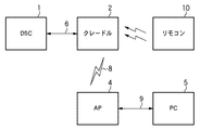
図2は、DSC及びカメラクレードル装置を備えるシステムの構成を示す図である。1はDSC、2はDSCを搭載するカメラクレードル装置である。DSC1及びカメラクレードル装置2は、USBインターフェースやDSC1への電源制御信号、DSC1の電源状態判別信号、DSC1のカメラクレードル装置2への搭載状態判別信号等の信号6を通す信号線によって接続されている。4はアクセスポイント(以下「AP」という。)、5は外部操作端末としてのパーソナルコンピュータ(以下「PC」という。)であり、有線LAN9によって接続されている。また、AP4は無線接続手段としての無線LAN8の信号によって、カメラクレードル装置2と接続されている。
FIG. 2 is a diagram illustrating a configuration of a system including a DSC and a camera cradle device.
図4は、DSC1をカメラクレードル装置2へ搭載した場合の前面概観図である。図5は、DSC1をカメラクレードル装置2へ搭載する方法を示す図である。図5において、102はDSC1の拡張コネクタであり、209はカメラクレードル装置2の拡張コネクタである。拡張コネクタ102及び拡張コネクタ209は、DSC1をカメラクレードル装置2に搭載して図4の状態にセットしたときに、上述の信号6を通す信号線を接続するために使用される。210はカメラクレードル装置2のUSBコネクタであり、USBケーブル(不図示)を介してPCやプリンタ(不図示)とUSBインターフェースとを接続するために使用されうる。211は外部電源ボタンであり、上述の信号6を通す信号線を用いてDSC1の電源を制御する。この部分の詳細は後述する。ここで、外部電源ボタンとは、カメラの電源のオンオフ動作を行う電源ボタンのうち、カメラの外部に接続される各種装置に搭載されたトグルスイッチをいう。230は赤外線受光部であり、不図示のリモートコントロールユニットからの赤外線を受光する。212はコピーボタンであり、DSC1内の画像データをカメラクレードル装置2内のストレージ(不図示)へ読み出すときの指示ボタンとして機能する。218は無線LAN用のアンテナであり、無線LAN8の信号によってAP4と接続を行うために使用される。カメラクレードル装置2の背面(不図示)には図1に示すDCジャック21が配置される。DCジャック21にACアダプタ20が接続されると、電力の供給が行われる。図5に示したように、DSC1をカメラクレードル装置2の上部に搭載することによって、拡張コネクタ102と拡張コネクタ209とが自動的に接続され、図4の状態にセットされる。カメラクレードル装置2は、DSC1を搭載した状態で、上下方向の首振り(チルト)や水平方向の回転(パン)が可能である。また、カメラクレードル装置2は、USBインターフェースを用いてDSC1にコマンドを送ることによって、ズーム動作も可能である。
FIG. 4 is a front view of the DSC 1 mounted on the
以下、上述した構成を用いて、本システムの基本的動作を説明する。 Hereinafter, the basic operation of this system will be described using the configuration described above.
DSC1のデータは、USB6によってカメラクレードル装置2へ、無線LAN8によってカメラクレードル装置2からAP4へ、有線LAN9によってAP4からPC5へ転送される。例えば、DSC1からのファインダー画像(320×240ドット程度の動画)は、上記のルートでPC5に送られる。PC5からDSC1へ転送される場合は、その逆となる。ユーザーは、転送された画像を見ながらPC5を操作して、パン、チルト、ズーム動作コマンドをカメラクレードル装置2に送信し、好みの撮影ポジションで撮影指示を行う。すると、対応した撮影コマンドが上記のルートでPC5からDSC1へと送られる。撮影コマンドを受けたDSC1は、例えば1600×1200ドットの静止画を撮影し、再び上記のルートでPC5へ送信する。このようにして、PC5を利用したリモート撮影が可能である。
The data of the
図7は、カメラクレードル装置2の概略内部ブロック図である。21はDCジャックであり、図1のACアダプタ20が接続されると、22の電源部を経由してカメラクレードル装置2各部へ電力が供給されて動作が開始する。200はカメラクレードル装置2の全体制御を司るCPUであり、214のシステムバスに接続されている。201はプログラムや各種データを記憶したROMである。202はプログラムをロードして実行したり、各種ワークとして使用されたりするRAMである。203はハードディスク及びハードディスクコントローラで構成される記憶装置である。230はリモートコントローラからの赤外線を受信する赤外線受光部である。204は無線LANの制御部であり、アンテナ218を経由して無線信号8によってAP4と接続されうる。205はUSBホストコントローラである。USB信号219は、拡張コネクタ209を経由して、信号6の一部としてDSC1に供給され、DSC1との通信に使用される。このような通信の一例としては、カメラクレードル装置2からのコマンド又はPC5からのコマンドの中継やDSC1からの画像データ及びそのデータのPC5への中継などが挙げられる。213はスイッチであり、その出力信号220は拡張コネクタ209を経由して、信号6の一部としてDSC1に供給され、その電源を制御する。スイッチ213の入力側の一端は電源Vccに接続され、もう一端は電源Vccに接続されない。206は出力ポートであり、その出力217によってスイッチ213を切換え、DSC1の電源制御を行う。出力217がLOWレベルの場合には、スイッチ213は下接点側にセットされる。出力217がHIGHレベルの場合には、スイッチ213は上接点側にセットされ、電源Vccが制御信号220に出力される。
FIG. 7 is a schematic internal block diagram of the
詳細は後述するが、制御信号220は、DSC1の内部電源ボタン32と等価の機能を有する。一定時間、制御信号220として電源Vccを出力することによって、DSC1の電源を制御することができる。207は入力ポートであり、上述の外部電源ボタン211が信号215によって接続され、上述のコピーボタン212が信号216によって接続されている。また、入力ポート207へは信号6の一部として信号221と信号222とが拡張コネクタ209経由で入力される。信号221と信号222とは、DSC1の電源状態及びDSC1のカメラクレードル装置2への搭載状態の検出に使用される。208はUSBファンクションコントローラであり、コネクタ210に接続された機器との通信に使用される。231はパン/チルト制御部であり、232のパン駆動部及び233のチルト駆動部を制御して、パン/チルト動作を行う。
Although details will be described later, the
図6は、DSC1のブロック図であり、本発明の好適な実施の形態に係る主要な部分を表している。100は本体制御部であり、システムバス105等を有しており、DSC1の全体制御を司る。101はシステムバス105に接続されたUSBファンクションコントローラであり、104のUSB信号が接続されている。48はバッテリー、103はバッテリー48から電力が供給される電源部であり、DSC1の各部で必要とされる電源として機能する。32は内部電源ボタンであり、その一端はバッテリー48へ、もう一端は電源部103のスイッチ端子109へ接続されている。DSC1の電源がオフ状態で、ユーザーが一定時間以上、内部電源ボタン32を押下すると(スイッチ32をオンにすると)、DSC1の電源が投入(オン)される。逆に、DSC1の電源がオン状態で、内部電源ボタン32を押下すると、DSC1の電源が遮断(オフ)される。106は電源部103のスイッチ端子109に接続された制御信号であり、USB信号104と共に拡張コネクタ102経由で信号6としてカメラクレードル装置2へ接続されている。制御信号106はカメラクレードル装置2上の制御信号220と等価であり、DSC1の電源を制御するために使用される。カメラクレードル装置2で出力ポート206の出力信号217を一定時間HIGHレベルにすると、制御信号106にはその期間だけ電源Vccが出力され、内部電源ボタン32を押下した場合と等価になる。これにより、カメラクレードル装置2は、信号217によりDSC1の電源の投入/遮断(電源のオンオフ)を行うことができる。107は電源部103の電源出力であり、拡張コネクタ102経由で信号6の一部としてカメラクレードル装置2へ接続されている。カメラクレードル装置2は、これを信号221で受けて、DSC1の電源が投入されているか、それとも遮断されているかを検知する。108はGNDへ接続されているが、DSC1のカメラクレードル装置2への搭載状態を検出する信号である。カメラクレードル装置2は、これを信号222で受けて、DSC1がカメラクレードル装置2へ搭載されているか否かを検知する。
FIG. 6 is a block diagram of the
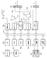
図1は、DSC1とカメラクレードル装置2のブロック図であり、説明のため両者の接続部を記載している。図1は、スイッチ213を光MOS FETで構成する場合を一例として示している。101はUSBファンクションコントローラである。USB信号104は、拡張コネクタ102、信号6の一部及び拡張コネクタ209を経由して、カメラクレードル装置2のUSBホストコントローラ205へ接続されている。48はバッテリーであり、103はバッテリー48から電力を供給され、DSC1の各部に必要な電源を供給する電源部である。32はDSC1の内部電源ボタンであり、電源部103のスイッチ端子109へ接続されている。通常は、スイッチ32がオフ状態で、スイッチ端子109はプルダウン抵抗110によってLOWレベルに設定されている。ユーザーがボタン32を一定時間押下すると、スイッチ端子109にバッテリー48の電圧が印加される。DSC1が電源オフの場合には電源が投入され、電源オンの場合には電源が遮断される。108はDSC1のカメラクレードル装置2への搭載状態を検出する信号であり、GNDへ接続されている。信号108は、拡張コネクタ102、信号6の一部及び拡張コネクタ209を経由して、入力ポート207の信号222へ接続される。信号222は、抵抗226でプルアップされており、DSC1がカメラクレードル装置2へ搭載されていない場合にはHIGHレベルとなる。DSC1がカメラクレードル装置2へ搭載されると、信号108によってGNDへ接続されるためにLOWレベルとなる。このように、DSC1がカメラクレードル装置2へ搭載されているか否かを判別することができる。107は、電源部103の電源出力であり、DCS1の電源がオンのときのみ出力される。信号107は、拡張コネクタ102、信号6の一部及び拡張コネクタ209を経由して、入力ポート207の信号221へ接続される。信号221は、抵抗227でプルダウンされており、DSC1がカメラクレードル装置2へ搭載され、かつ、DSC1の電源が投入されているときのみHIGHレベルとなる。すなわち、信号222でDCS1の搭載の有無、信号221でDSC1が搭載されているときの電源状態を判別可能である。213は光MOS FETである。223は光電流制限用の抵抗で、一端は光ダイオードのカソード端子、もう一端は接地されている。また、光ダイオードのアノード端子には、出力ポート206の出力217が接続されている。FETの一端には電源Vccが、FETのもう一端には制御信号220が接続されている。制御信号220は、拡張コネクタ209、信号6の一部及び拡張コネクタ102を経由して、電源部103のスイッチ端子109へ接続される。信号217を所定時間HIGHレベルにすると、制御信号220は電源Vccレベルとなり、スイッチ端子109に電源Vccを印加することができる。すなわち、内部電源ボタン32を押下したときと等価な状態となる。211、212はそれぞれ電源ボタン、コピーボタンであり、信号215、216で入力ポート207へ接続され、それぞれ抵抗224、225でプルアップされている。よって、通常時はHIGHレベルであり、ボタンが押下されるとLOWレベルとなる。また、カメラクレードル装置2はDCジャック21を備え、ACアダプタ20が接続されることにより、電源部22経由でカメラクレードル装置2各部へ電力が供給され動作することができる。
FIG. 1 is a block diagram of the
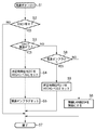
以上の構成によるDSC1の電源制御方法を図8を用いて説明する。図8は、カメラクレードル装置2からDSC1の電源を制御する方法を示すフローチャートである。本フローチャートは、すでにカメラクレードル装置2の電源が投入された状態において、ユーザーがカメラクレードル装置2の外部電源ボタン211を押下したところから開始する。
A power supply control method of the
ステップS1では、カメラクレードル装置2は、外部電源ボタン211の押下を検出する。
In step S <b> 1, the
ステップS2では、カメラクレードル装置2は、入力信号222のレベルをチェックする。入力信号222がLOWレベルであれば(ステップS2で「Yes」)、DSC1が搭載されていると判断し、ステップS3へ進む。入力信号222がHIGHレベルであれば(ステップS2で「No」)、DSC1が搭載されていないと判断し、ステップS7に進んで処理を終了する。
In step S <b> 2, the
ステップS3では、カメラクレードル装置2は、DSC1の電源のオンオフ状況を確認するために入力信号221のレベルをチェックする。入力信号221がLOWレベルであれば(ステップS3で「Yes」)、DSC1の電源がオフされているのでステップS4へ進む。入力信号221がHIGHレベルであれば(ステップS3で「No」)、DSC1の電源がオンされているので、ステップS8へ進む。
In step S3, the
ステップS4では、カメラクレードル装置2は、制御信号217を所定時間HIGHレベルにセットすることによって、DSC1の電源を投入する。
In step S4, the
ステップS5では、カメラクレードル装置2は、カメラクレードル装置2側でDSC1の電源を投入したことを示す電源オンフラグをセットして、ステップS7に進んで処理を終了する。これ以降は、LAN上の機器、例えばPC5からのアクセスに応答する「ネットワークモード」で動作する。ネットワークモードとは、例えばDSC1からのファインダー画像(320×240ドット程度の動画)がDSC1→カメラクレードル装置2→AP4→PC5のルートでPC5に送られるモードである。ユーザーが送られた画像を見ながらPC5でパン/チルト/ズーム等の指示を行った後に撮影指示を行うと、これに対応するパン/チルト/ズーム/撮影コマンドが上記と逆のルートでPC5からDSC1又はカメラクレードル装置2へ送られる。撮影コマンドを受けたDSC1は、例えば1600×1200ドットの静止画を撮影し、再び上記のルートでPC5へ送信する。このようにしてPC5を利用するリモート撮影が、典型的なネットワークモードのアプリケーションである。
In step S5, the
ステップS8では、カメラクレードル装置2は、電源オンフラグをチェックする。これはステップS5でセットされるフラグであり、カメラクレードル装置2がDSC1の電源を投入した場合にセットされるフラグである。ステップS8で電源オンフラグが既にセットされている場合には(ステップS8で「Yes」)、ステップS9で制御信号217を所定時間HIGHレベルにする。これによってDSC1の電源を遮断し、ステップS7に進んで処理を終了する。ステップS8で電源オンフラグがセットされていない(カメラクレードル装置2側でDSC1の電源を投入していないのに、DSC1の電源がオンの状態になっている)場合には(ステップS8で「No」)、ステップS6で無線LAN部204を無効にする。或いは、これ以降、無線LAN部204を介してアクセスポイント4を含む外部のネットワーク機器とのデータ転送を遮断する。その後、ステップS7に進んで処理を終了する。すなわち、DSC1の内部電源ボタン32によって電源が投入された「ローカルモード」である。ローカルモードは、DSC1の基本機能であり、DSC1による画像の撮影/再生の他、DSC1とカメラクレードル装置2との通信までを含んだモードである。例えば、典型的なローカルモードのアプリケーションとしては、以下の例が挙げられる。すなわち、ダイレクト転送ボタン47によるDSC1からカメラクレードル装置2への画像転送やカメラクレードル装置2のコピーボタン212の操作によるDSC1からカメラクレードル装置2への画像コピーなどである。
In step S8, the
ユーザーが明示的にモード変更した場合を除いて、DSC1の動作はネットワークモードとローカルモードとで差異はなく、カメラクレードル装置2側でネットワーク上の外部機器のアクセスを遮断するか否かが異なる。また、ローカルモードにおいて、クレードル装置2の電源ボタン211の押下を検出したとしても、ローカルモードであることを示すためにステップS6においてDSC1の電源の遮断指示は行わないように制御している。
Except when the user explicitly changes the mode, the operation of the
以上述べたように、DSC1の内部電源ボタンを押下した場合には、ネットワークからのアクセスを遮断したローカルモードで動作する。そして、カメラクレードル装置で外部電源ボタンを押下した場合には、ネットワークからのアクセスを許容するネットワークモードで動作する。これにより、ユーザーによる直感的な操作で明示的に動作モードを指定可能なシステムを実現することができる。
As described above, when the internal power button of the
また、カメラクレードル装置の操作では、ローカルモード動作中には電源の遮断ができないため、ローカルモード動作中に不用意に電源を遮断することのないシステムを実現することができる。
[第2の実施形態]
第1の実施形態では、DSC1の内部電源ボタン32とカメラクレードル装置2の外部電源ボタン211とを用いて、電源制御を行う場合を説明した。これに対し、第2の実施形態では、さらにリモートコントロールユニット(以下「リモコン」という。)による電源制御を追加する。
Further, in the operation of the camera cradle device, since the power cannot be shut off during the local mode operation, a system that does not inadvertently shut off the power during the local mode operation can be realized.
[Second Embodiment]
In the first embodiment, the case where power control is performed using the
以下の説明では、第1の実施形態に追加した部分や異なる部分を中心に説明する。なお、第1の実施形態と同様の構成要素については同一の符号を付している。 In the following description, the part added to the first embodiment and different parts will be mainly described. In addition, the same code | symbol is attached | subjected about the component similar to 1st Embodiment.
図9は、DSC1及びカメラクレードル装置2を備えるカメラクレードルシステムの構成を示す図である。10は赤外線発光部を備えたリモコン、2は赤外線受光部を備えたカメラクレードル装置であり、リモコン10の制御下でカメラクレードル装置2を動作させることができる。その他の部分は第1の実施形態と同様である。
FIG. 9 is a diagram illustrating a configuration of a camera cradle system including the
図10は、リモコン10の概観図である。150は赤外線発光部、151は赤外光である。リモコン10は、カメラクレードル装置2の赤外線受光部230に対して、リモコン10で押下されたキーをコード化して送信する。152はネットワークモード用の外部電源ボタン(以下「ネットワークモード外部電源ボタン」という。)、153はローカルモード用の外部電源ボタン(以下、「ローカルモード外部電源ボタン」という。)である。154はズームイン指示キー、155はズームアウト指示キーであり、カメラクレードル装置2経由でDSC1のズーム倍率を切換える。156はチルトアップ指示キー、159はチルトダウン指示キーであり、カメラクレードル装置2のチルト機構により、DSC1を上下方法の向きを変える。157、158はパン指示キーであり、カメラクレードル装置2のパン機構により、DSC1の横方向の向きを変える。160はHOMEキーであり、上記のパン、チルト、ズームで変更されたDSC1の位置を初期位置へ移動させる。
FIG. 10 is an overview of the
以上の構成によるカメラクレードル装置2の電源制御方法を図11、12を用いて説明する。図11、12は、ユーザーがリモコン10の電源制御キーを押下し、対応するキーコードが赤外線によりカメラクレードル装置2に送信される方法を示すフローチャートである。図11のフローチャートは、すでにカメラクレードル装置2の電源が投入された状態において、ローカルモード外部電源ボタン153が押下され、そのキーコードを受信したところから開始する。
A method of controlling the power supply of the
ステップS21で、カメラクレードル装置2は、ローカルモード外部電源ボタン153のキーコードを受信する。
In step S21, the
ステップS22では、カメラクレードル装置2は、入力信号222のレベルをチェックする。入力信号222のレベルがLOWレベルであれば(ステップS22で「Yes」)、DSC1が搭載されていると判断してステップS23へ進む。入力信号222のレベルがHIGHレベルであれば(ステップS22で「No」)、DSC1が搭載されていないので、ステップS26に進んで処理を終了する。
In step S22, the
ステップS23では、カメラクレードル装置2は、DSC1の電源のオンオフ状況を確認するために入力信号221のレベルをチェックする。入力信号221のレベルがLOWレベルであれば(ステップS23で「Yes」)、DSC1の電源がオフされていると判断して、ステップS24へ進む。入力信号221のレベルがHIGHレベルであれば(ステップS23で「No」)、DSC1の電源がオンされているので、ステップS27へ進む。
In step S23, the
ステップS24では、カメラクレードル装置2は、制御信号217を所定時間HIGHレベルにすることによって、DSC1の電源を投入する。
In step S24, the
ステップS25では、カメラクレードル装置2は、無線LAN部204を無効にするか、又は、これ以降のネットワークからのコマンドやデータをDSC1へ中継しない。その後、ステップS26に進んで処理を終了する。この場合、「ローカルモード」で動作し、かつ、図8のステップS5のようなフラグセットのステップがないので、電源オンフラグもセットされていない。よって、この状態から外部電源ボタン211を押下すると、図8のステップS1→ステップS2→ステップS3→ステップS8→ステップS6→ステップS7のルートを通り、電源の制御がなされないで終了する。すなわち、ローカルモードにおいて外部電源ボタン153でDSC1の電源を投入した場合は、カメラクレードル装置2の外部電源ボタン211ではDSC1の電源を遮断することができない。
In step S25, the
ステップS27では、カメラクレードル装置2は、制御信号217を所定時間HIGHレベルにすることによって、DSC1の電源を遮断し、ステップS26に進んで処理を終了する。この場合は、図8のステップS8のように電源オンフラグのチェックをするステップがないので、電源投入を32、211、152又は153のいずれの電源制御ボタンでした場合であっても、DSC1の電源は遮断される。
In step S27, the
図12のフローチャートは、すでにカメラクレードル装置2の電源が投入された状態において、ネットワークモード外部電源ボタン152が押下され、そのキーコードを受信したところから開始する。
The flowchart of FIG. 12 starts when the network mode
ステップS31では、カメラクレードル装置2は、ネットワークモード外部電源ボタン152のキーコードを受信する。
In step S31, the
ステップS32では、カメラクレードル装置2は、入力信号222のレベルをチェックする。入力信号222のレベルがLOWレベルであれば(ステップS32で「Yes」)、DSC1が搭載されていると判断しステップS33へ進む。入力信号222のレベルがHIGHレベルであれば(ステップS32で「No」)、DSC1が搭載されていないと判断し、ステップS37に進んで処理を終了する。
In step S <b> 32, the
ステップS33では、カメラクレードル装置2は、DSC1の電源のオンオフ状態を確認するために入力信号221のレベルをチェックする。入力信号221のレベルがLOWレベルであれば(ステップS33で「Yes」)、DSC1の電源がオフされていると判断し、ステップS34へ進む。入力信号221のレベルがHIGHレベルであれば(ステップS33で「No」)、DSC1の電源がオンされていると判断し、ステップS38へ進む。
In step S33, the
ステップS34では、カメラクレードル装置2は、制御信号217を所定時間HIGHレベルにすることによって、DSC1の電源を投入する。
In step S34, the
ステップS35では、カメラクレードル装置2は、カメラクレードル装置の電源がオンであることを示す電源オンフラグをセットして、ステップS37に進んで処理を終了する。この電源オンフラグは、図8のステップS5でセットされるフラグと等価である。これ以降は、LAN上の機器、例えばPC5からのアクセスに応答する「ネットワークモード」で動作する。
In step S35, the
ステップS38では、カメラクレードル装置2は、電源オンフラグをチェックする。これは、ステップS35又は図8のステップS5でセットされるフラグであり、152又は211の電源制御ボタンで電源を投入したときにセットされる。ステップS38で電源オンフラグがセットされている場合には(ステップS38で「Yes」)、ステップS39で制御信号217を所定時間HIGHレベルにする。これによって、DSC1の電源が遮断され、ステップS37に進んで処理を終了する。ステップS38で電源オンフラグがセットされていない場合には(ステップS38で「No」)、ステップS36で無線LAN部204を無効にする。或いは、これ以降の無線LAN部204を介してアクセスポイント4を含む外部のネットワーク機器とのデータ転送を遮断する。その後、ステップS37に進んで処理を終了する。この場合は、32又は153の電源制御ボタンでDSC1の電源が投入されたということであり、「ローカルモード」であると判断できる。この場合、ステップS36で無線LAN部204は無効になっており、ネットワーク機器からのアクセスは遮断される。
In step S38, the
以上述べたように、DSCの内部電源ボタン又はリモコンのローカルモード外部電源ボタンを押下した場合には、ネットワークからのアクセスを遮断したローカルモードで動作する。カメラクレードル装置の外部電源ボタン又はリモコンのネットワークモード外部電源ボタンを押下した場合には、ネットワークからのアクセスを許容する「ネットワークモード」で動作する。これにより、ユーザーによる直感的な操作で明示的に動作モードを指定可能なシステムを実現することができる。 As described above, when the internal power button of the DSC or the local mode external power button of the remote control is pressed, the operation is performed in the local mode in which access from the network is blocked. When the external power button of the camera cradle device or the network mode external power button of the remote control is pressed, the camera operates in the “network mode” that allows access from the network. Thereby, it is possible to realize a system in which an operation mode can be explicitly specified by an intuitive operation by a user.
また、カメラクレードル装置の操作又はリモコンのネットワークモード外部電源ボタンでは、ローカルモード動作中には電源の遮断ができないため、ローカルモード動作中に不用意に電源を遮断することのないシステムを実現することができる。
[第3の実施形態]
第1の実施形態では、DSC1の内部電源ボタン32とカメラクレードル装置2の外部電源ボタン211とで電源制御を行う場合を説明した。また、第2の実施形態では、DSC1の内部電源ボタン32とカメラクレードル装置2の外部電源ボタン211とリモコンの外部電源ボタン152、153とで電源制御を行う場合を説明した。これに対し、第3の実施形態では、さらに外部操作端末としてのパーソナルコンピュータ(本実施形態ではPC5)でも電源制御を行う。
Also, the camera cradle device operation or the remote mode network mode external power button cannot be turned off during local mode operation, so a system that does not inadvertently cut off power during local mode operation is realized. Can do.
[Third Embodiment]
In the first embodiment, the case where the power control is performed by the
以下の説明では、第1、第2の実施形態に追加した部分や異なる部分を中心に説明する。図13は、外部操作端末の一例としてのPC5の画面を示す図である。50は操作画面全体の一例である。51はDSC1、カメラクレードル装置2及びAP4を経由して配信されるファインダー画像である。52、53、54、55はパン/チルトボタンである。56はレリーズボタン、57は外部電源ボタン、58は終了ボタンである。59はズーム用のスクロールバー、60はサムネイル領域、61はサムネイル画像、62はサムネイル領域60をスクロールさせるスクロールバーである。
In the following description, the description will focus on the parts added to the first and second embodiments and the different parts. FIG. 13 is a diagram illustrating a screen of the
上述の実施形態で説明したが、ネットワークモードの場合において、PC5によってカメラクレードル装置2及びDSC1に対する制御が有効になる。
As described in the above-described embodiment, in the case of the network mode, the control for the
ネットワークモードの場合では、例えばDSC1→カメラクレードル装置2→AP4→PC5のルートでPC5にファインダー画像51が送られる。このファインダー画像51を見ながら、ユーザーは52、53、54、55のパン/チルトボタンや59のズームスクロールバーを操作する。すると、対応するコマンドが、上記と逆のルートでカメラクレードル装置2へ送信される。カメラクレードル装置2は、パン/チルトコマンドの場合は、パン/チルト制御部231により、パン駆動部232及びチルト駆動部233を制御してパン/チルトを実行する。カメラクレードル装置2は、ズームコマンドの場合は、USBインターフェースを介してコマンドをDSC1へ転送し、ズーム動作を実行させる。このようにして所望の画像位置が得られたら、レリーズボタン56の選択動作に応じてカメラクレードル装置2へ撮影コマンドを送信する。撮影コマンドを受けたカメラクレードル装置2は、USBインターフェースによって、コマンドをDSC1へ転送し、撮影を実行させる。撮影後の画像データは、上記のルートでPC5へ送られる。
In the case of the network mode, for example, the
以下、図14、図16、図17、図18のカメラクレードル装置2のフローチャ−トを用いて、PC5の外部電源ボタン57を用いた電源制御部の説明を行う。
Hereinafter, the power control unit using the
図14のフローチャートは、すでにカメラクレードル装置2の電源が投入された状態において、PC5の外部電源ボタン57の選択動作を検出したことを示すキーコードを受信したところから開始する。
The flowchart of FIG. 14 starts when a key code indicating that the selection operation of the
ステップS51では、カメラクレードル装置2は、外部電源ボタン57のキーコードを受信する。
In step S51, the
ステップS52では、カメラクレードル装置2は、入力信号222のレベルをチェックする。入力信号222のレベルがLOWレベルであれば(ステップS52で「Yes」)、DSC1が搭載されていると判断し、ステップS53へ進む。入力信号222のレベルがHIGHレベルであれば(ステップS52で「No」)、DSC1が搭載されていないと判断し、ステップS61で外部電源ボタン57の無効コマンドをPC5へ送信した後、ステップS57に進んで処理を終了する。PC5は無効コマンドを受け取ると、操作画面を変更して図15の57に示すように外部電源ボタンをグレイアウトし、押されても反応しないようにする。
In step S52, the
ステップS53では、カメラクレードル装置2は、DSC1の電源のオンオフ状況を確認するために入力信号221のレベルをチェックする。入力信号221のレベルがLOWレベルであれば(ステップS53で「Yes」)、DSC1の電源がオフされていると判断し、ステップS54へ進む。入力信号221のレベルがHIGHレベルであれば(ステップS53で「No」)、DSC1の電源がオンされていると判断し、ステップS57へ進む。
In step S53, the
ステップS54では、カメラクレードル装置2は、制御信号217を所定時間HIGHレベルにすることによって、DSC1の電源を投入する。
In step S54, the
ステップS55では、カメラクレードル装置2は、外部の操作によってDSC1の電源がオンとなったことを示す電源オンフラグをセットして、ステップS56に進んで処理を終了する。この電源オンフラグは、図8のステップS5、図12のステップS35でセットされるフラグと等価である。これ以降は、LAN上の機器、例えばPC5からのアクセスに応答する「ネットワークモード」で動作する。
ステップS57では、電源オンフラグをチェックする。これはステップS55、図8のステップS5又は図12のステップS35でセットされるフラグであり、57、152又は211の電源制御ボタンで電源が投入されたときにセットされる。ステップS57で電源オンフラグがセットされている場合には(ステップS57で「Yes」)、ステップS58で制御信号217を所定時間HIGHレベルにすることによって、DSC1の電源を遮断し、ステップS56に進んで処理を終了する。ステップS57で電源オンフラグがセットされていない場合には(ステップS57で「No」)、ステップS59でステップS61と同様に外部電源ボタン57の無効コマンドをPC5へ送信する。その後、ステップS60で無線LAN部204を無効にするか、又は、これ以降の無線LAN部204を介してDSC1と外部のネットワーク機器とののデータ転送を遮断し、ステップS56に進んで処理を終了する。この場合は、32又は153の電源制御ボタンで電源を投入されたということであり、「ローカルモード」であると判断できる。この場合、ステップS60で無線LAN部204は無効になっており、ネットワーク機器からのアクセスは遮断される。
In step S55, the
In step S57, the power-on flag is checked. This is a flag set in step S55, step S5 in FIG. 8 or step S35 in FIG. 12, and is set when the power is turned on with the
図16は、図8と同様に、ユーザーがカメラクレードル装置2の外部電源ボタン211を押下し、それを検出したところから開始する。図8との違いは、ステップS70、S71、S72、S73が追加されている点である。図16のステップ2でDSC1が搭載されていないと判断された場合には(ステップS2で「No」)、ステップS73で外部電源ボタン57の無効コマンドをPC5へ送信し、ステップS7に進んで処理を終了する。このルートはDSC1が非搭載の状態である。ステップS2でDSC1が搭載され(ステップS2で「Yes」)、ステップS3でDSC1の電源がオフと判断された場合には(ステップS3で「Yes」)、以下の処理を実行する。すなわち、ステップS4でDSC1の電源を投入し、ステップS70で外部電源ボタン57の有効化コマンドをPC5へ送信する。PC5は有効化コマンドを受け取ると、操作画面を変更して、図13の57のように外部電源ボタンを表示し、ボタンとして有効にする。次いで、ステップS5でカメラクレードル装置2が電源を投入したことを示す電源オンフラグをセットして、ステップS7に進んで処理を終了する。このルートは「ネットワークモード」の動作である。ステップS2でDSC1が搭載され(ステップS2で「Yes」)、ステップS3でその電源がオン(ステップS3で「No」)、ステップS8で電源オンフラグ有り(ステップS8で「Yes」)と判断された場合には、以下の処理を行う。すなわち、ステップS9でDSC1の電源を遮断した後、ステップS71で外部電源ボタン57の有効化コマンドをPC5へ送信して終了する。このルートは電源オフの状態である。ステップS2でDSC1が搭載され(ステップS2で「Yes」)、ステップS3でその電源がオン(ステップS3で「No」)、ステップS8で電源オンフラグなし(ステップS8で「No」)と判断された場合には、以下の処理を行う。すなわち、ステップS72でステップS73と同様に、外部電源ボタン57の無効化コマンドをPC5へ送信する。次いで、ステップS6で無線LAN部204を無効にするか、又は、これ以降の無線LAN部204からDSC1へのデータ転送を遮断し、ステップS7に進んで処理を終了する。このルートは「ローカルモード」の動作である。
FIG. 16 starts from when the user presses the
図17は、図11と同様にユーザーがリモコン10のローカルモード外部電源ボタン153を押下し、それを検出したところから開始する。図11との違いは、ステップS74、S75、S76が追加されている点である。図17のステップ22でDSC1が搭載されていないと判断された場合には(ステップS22で「No」)、ステップS76で外部電源ボタン57の無効コマンドをPC5へ送信し、ステップS26に進んで処理を終了する。このルートはDSC1が非搭載の状態である。ステップS22でDSC1が搭載され(ステップS22で「Yes」)、ステップS23でDSC1の電源がオンと判断された場合には(ステップS23で「No」)、以下の処理を行う。すなわち、ステップS27でDSC1の電源を遮断した後、ステップS75で外部電源ボタン57の有効化コマンドをPC5へ送信して終了する。このルートは電源オフの状態である。ステップS22でDSC1が搭載され(ステップS22で「Yes」)、ステップS23でその電源がオフと判断された場合には(ステップS23で「Yes」)、以下の処理を行う。すなわち、ステップS24でDSC1の電源を投入し、ステップS74で外部電源ボタン57の無効化コマンドをPC5へ送信する。次いで、ステップS25で無線LAN部204を無効にするか、又は、これ以降の無線LAN部204からDSC1へのデータ転送を遮断し、ステップS26に進んで処理を終了する。このルートは「ローカルモード」の動作である。
FIG. 17 starts from when the user presses the local mode
図18は、図12と同様にユーザーがリモコン10のネットワークモード外部電源ボタン152を押下し、それを検出したところから開始する。図12との違いは、ステップS77、S78、S79、80が追加されている点である。図18のステップS32でDSC1が搭載されていないと判断された場合には(ステップS32で「No」)、ステップS80で外部電源ボタン57の無効コマンドをPC5へ送信し、ステップS37に進んで処理を終了する。このルートはDSC1が非搭載の状態である。ステップS32でDSC1が搭載され(ステップS33で「Yes」)、ステップS33でDSC1の電源がオフと判断された場合には(ステップS33で「Yes」)、以下の処理を行う。すなわち、ステップS34でDSC1の電源を投入し、ステップS77で外部電源ボタン57の有効化コマンドをPC5へ送信する。次いで、ステップS35で外部の操作によってDSC1の電源がオンとなったことを示す電源オンフラグをセットして、ステップS37に進んで処理を終了する。この電源オンフラグは、図16のステップS5でセットするフラグと等価である。このルートは「ネットワークモード」の動作である。ステップS32でDSC1が搭載され(ステップS32で「Yes」)、ステップS33でその電源がオン(ステップS33で「No」)、ステップS38で電源オンフラグ有り(ステップS38で「Yes」)と判断された場合には、以下の処理を行う。すなわち、ステップS39でDSC1の電源を遮断した後、ステップS78で外部電源ボタン57の有効化コマンドをPC5へ送信して終了する。このルートは電源オフの状態である。ステップS32でDSC1が搭載され(ステップS32で「Yes」)、ステップS33でその電源がオン(ステップS32で「No」)、ステップS38で外部の操作によってDSC1の電源がオンとなったことを示す電源オンフラグなし(ステップS38で「No」)と判断された場合には、以下の処理を行う。すなわち、ステップS79でステップS80と同様に外部電源ボタン57の無効化コマンドをPC5へ送信する。次いで、ステップS36で無線LAN部204を無効にするか、又は、これ以降の無線LAN部204からDSC1へのデータ転送を遮断し、ステップS37に進んで処理を終了する。このルートは「ローカルモード」の動作である。
FIG. 18 starts when the user presses the network mode
以上述べたように、DSCの内部電源ボタン又はリモコンのローカルモード外部電源ボタンを押下した場合には、ネットワークからのアクセスを遮断したローカルモードで動作する。カメラクレードル装置の外部電源ボタン、リモコンのネットワークモード外部電源ボタン又は外部操作端末の外部電源ボタンを押下した場合には、ネットワークからのアクセスを許容する「ネットワークモード」で動作する。これにより、ユーザーによる直感的な操作で明示的に動作モードを指定可能なシステムを実現することができる。 As described above, when the internal power button of the DSC or the local mode external power button of the remote control is pressed, the operation is performed in the local mode in which access from the network is blocked. When the external power button of the camera cradle device, the network mode external power button of the remote control, or the external power button of the external operation terminal is pressed, it operates in the “network mode” that allows access from the network. Thereby, it is possible to realize a system in which an operation mode can be explicitly specified by an intuitive operation by a user.
また、カメラクレードル装置の操作、リモコンのネットワークモード外部電源ボタン又は外部操作端末の操作では、ローカルモード動作中には電源の遮断ができない。これにより、ローカルモード動作中に不用意に電源を遮断することのないシステムを実現することができる。 Further, the operation of the camera cradle device, the remote mode network mode external power button or the external operation terminal cannot be used to shut off the power during the local mode operation. Thereby, it is possible to realize a system that does not inadvertently shut down the power supply during the local mode operation.
さらに、外部操作端末の外部電源ボタンが使用不可の場合には、画面上で操作不可と判別できるように外部電源ボタンの表示を変更し、さらにボタン操作を無効化する。これにより、ユーザーに操作の可/不可を明示することができ、かつ、誤操作を防止することができるシステムを実現することができる。
[第4の実施形態]
上記の実施形態では、DSCの電源がオフ状態でカメラクレードル装置に搭載される場合を想定して説明した。これに対し、第4の実施形態は、DSCの電源をオンの状態でカメラクレードル装置に搭載する。また、上記の実施形態ではDSC1の搭載有無を入力信号222を読み出すことで判別していた。これに対し、本実施形態では、カメラクレードル装置にDSCを搭載したときにインタラプトを発生させ、そのときのDSC1の電源状況を判断する。
Further, when the external power button of the external operation terminal is unusable, the display of the external power button is changed so that it can be determined that the operation is impossible on the screen, and the button operation is invalidated. As a result, it is possible to realize a system that can clearly indicate to the user whether the operation is possible or not, and can prevent an erroneous operation.
[Fourth Embodiment]
In the above embodiment, the case where the DSC is mounted on the camera cradle apparatus in the off state has been described. In contrast, in the fourth embodiment, the DSC is mounted on the camera cradle device with the power on. In the above embodiment, whether the
以下の説明では、上記の実施形態に追加した部分や異なる部分を中心に説明する。 In the following description, the part added to the above embodiment and different parts will be mainly described.
図19は、カメラクレードル装置2の概略ブロック図である。図19では、第1の実施形態で説明に用いた図7に対し、システムバス214に接続されたインタラプトコントローラ234が追加されている。入力信号222は、インタラプト端子235に接続されている。
FIG. 19 is a schematic block diagram of the
図20は、DSC1とカメラクレードル装置2のブロック図であり、説明のため両者の接続部を示している。また、図20も図19と同様に、第1の実施形態で説明に用いた図1に対し、インタラプトコントローラ234と、入力信号222が接続されたインタラプト端子235とが追加されている。インタラプトコントローラ234は、インタラプト端子235の立下りエッジでCPU200に対しインタラプトを発生する。入力信号222は、DSC1が搭載されていないときには、抵抗226でプルアップされてHIGHレベルとなる。DSC1が搭載されると、GNDに接続された信号108と接続されてLOWレベルとなる。すなわち、入力信号222の接続されたインタラプト端子235には立下りエッジが入力され、CPU200に対してインタラプトを発生する。
FIG. 20 is a block diagram of the
以上の構成によるカメラクレードル装置2の動作を図21を用いて説明する。図21は、上述したように、カメラクレードル装置2にDSC1を搭載し、CPU200にインタラプトが発生したところから開始するインタラプト処理である。
The operation of the
ステップS41では、CPU200にインタラプトが発生する。
In step S41, an interrupt is generated in
ステップS42では、カメラクレードル装置2は、入力信号222のレベルをチェックして、DSC1の有無をチェックする。DSC1を搭載したことによるインタラプトが発生しているので、本来ならばDSC1有りと判断してステップS43へ進む。しかしながら、ここでDSC無しと判断された場合には、何らかの原因で不正なインタラプトが発生したということであり、ステップS45でインタラプト処理を終了する。
In step S42, the
ステップS43では、カメラクレードル装置2は、DSC1の電源のオンオフ状況を確認するために入力信号221のレベルをチェックする。入力信号221のレベルがLOWレベルであれば、DSC1の電源はオフ状態であると判断し、ステップS45でインタラプト処理を終了する。この後は、上述の実施形態で述べたように、DSC1、カメラクレードル装置2、リモコン10及びPC5の各種電源スイッチの押下の検出を待つ。ステップS43で入力信号221がHIGHレベルのときには、DSC1の電源はオン状態であり、続くステップS44で無線LAN部204を無効にする。或いは、これ以降の無線LAN部204からDSC1へのデータ転送を遮断し、ステップS45でインタラプト処理を終了する。このステップS41→ステップS42→ステップS43→ステップS44→ステップS45のルートは、「ローカルモード」の動作である。第1の実施形態で述べたように、例えば、この後のDSC1のダイレクト転送ボタン47やカメラクレードル装置2のコピーボタン212等の操作により、DSC1からカメラクレードル装置への画像コピーを行うことができる。これは、ローカルモードの典型的なアプリケーションである。
In step S43, the
以上述べたように、DSCの電源をオン状態でカメラクレードル装置に載せた場合には、ローカルモードで動作する。これにより、DSC単体での撮影→DSCのカメラクレードル装置への搭載→DSCからカメラクレードル装置への画像コピーといった一連の動作をDSCの電源を操作することなく、最小限の操作で実行可能なシステムを実現することができる。
[第5の実施形態]
上記の実施形態では、カメラクレードル装置2の電源が常にオンの状態にあることを前提として説明を行ったが、図22を用いてカメラクレードル装置2の電源が投入された場合の動作を説明する。図22は、カメラクレードル装置2のDCジャック21にACアダプタ20が接続され、カメラクレードル装置2の電源が投入されたところから始まっており、本実施形態に係るところを中心に記載している。
As described above, when the DSC is turned on and mounted on the camera cradle device, it operates in the local mode. As a result, a system capable of performing a series of operations, such as taking a single DSC, mounting the DSC on the camera cradle device, and copying the image from the DSC to the camera cradle device, without operating the DSC power supply. Can be realized.
[Fifth Embodiment]
In the above embodiment, the description has been made on the assumption that the power supply of the
ステップS51では、カメラクレードル装置2の電源が投入される。
In step S51, the
ステップS52では、カメラクレードル装置2は、CPU200の内部レジスタ、無線LAN制御部204、出力ポート206、USBホストコントローラ205、USBファンクションコントローラ208等の初期化処理を行う。
In step S52, the
ステップS53では、カメラクレードル装置2は、入力信号222のレベルをチェックして、DSC1の有無をチェックする。入力信号222がHIGHレベルで、DSC無しと判断された場合には(ステップS53で「No」)、ステップS56で電源オン時の初期化処理を終了する。入力信号222がLOWレベルで、DSCありと判断された場合には(ステップS53で「Yes」)、ステップS54に進む。
In step S53, the
ステップS54では、カメラクレードル装置2は、入力信号221のレベルをチェックする。入力信号221のレベルがLOWレベルであれば、DSC1の電源はオフ状態であり(ステップS54で「No」)、ステップS56で電源オン時の初期化処理を終了する。入力信号221がHIGHレベルのときには、DSC1の電源はオン状態であり(ステップS54で「Yes」)、続くステップS55で無線LAN部204を無効にする。或いは、これ以降の無線LAN部204からDSC1へのデータ転送を遮断し、ステップS56で電源オン時の初期化処理を終了する。このステップS51→ステップS52→ステップS53→ステップS54→ステップS55→ステップS56のルートは、「ローカルモード」の動作である。上述したように、例えば、この後のDSC1のダイレクト転送ボタン47やカメラクレードル装置2のコピーボタン212等の操作により、DSC1からカメラクレードル装置への画像コピーを行うことができる。これは、ローカルモードの典型的なアプリケーションである。このように、DSCの電源をオン状態でカメラクレードル装置に載せた後、カメラクレードル装置の電源をオンした場合には、「ローカルモード」で動作させることができる。
In step S54, the
以上述べたように、DSCの電源をオン状態でカメラクレードル装置に載せた場合には、ローカルモードで動作する。これにより、DSC単体での撮影→DSCのカメラクレードル装置への搭載→DSCからカメラクレードル装置への画像コピーといった一連の動作をDSCの電源を操作することなく、少ない操作で実行可能なシステムを実現することができる。 As described above, when the DSC is turned on and mounted on the camera cradle device, it operates in the local mode. This realizes a system that can perform a series of operations such as shooting with a single DSC → mounting a DSC on a camera cradle device → copying an image from the DSC to the camera cradle device with few operations without operating the DSC power supply. can do.
また、DSCの電源をオン状態でカメラクレードル装置に載せた後、カメラクレードル装置の電源をオンした場合でも、ローカルモードで動作する。これにより、カメラクレードル装置の電源を入れ忘れてDSCを搭載した場合でも、最小限の操作でローカルモードが実行可能なシステムを実現することができる。
[他の実施形態]
上記の実施形態では、カメラクレードル装置とアクセスポイントとを無線LANで接続し、アクセスポイントと外部操作端末とを有線LANで接続する場合を一例として説明した。しかしながら、本発明の好適な実施の形態は、これらのI/Fに限られるものではない。例えば、アクセスポイントを経由せずに、無線によるアドホックモードや有線の直結によって、カメラクレードル装置とパーソナルコンピュータとを接続してもよい。
Further, even when the power of the camera cradle apparatus is turned on after being mounted on the camera cradle apparatus with the DSC power turned on, the camera operates in the local mode. This makes it possible to realize a system that can execute the local mode with a minimum operation even when the DSC is installed without turning on the power of the camera cradle device.
[Other Embodiments]
In the above embodiment, the case where the camera cradle device and the access point are connected by the wireless LAN and the access point and the external operation terminal are connected by the wired LAN has been described as an example. However, preferred embodiments of the present invention are not limited to these I / Fs. For example, the camera cradle device and the personal computer may be connected by a wireless ad hoc mode or wired direct connection without going through an access point.
上記の実施形態では、ローカルモード外部電源ボタンを優先し、ネットワークモード外部電源ボタンではローカルモード動作中は電源を遮断できず、ローカルモード外部電源ボタンはどのモードでも電源を遮断できるように構成されている。しかしながら、逆にネットワークモード外部電源ボタンを優先してもよい。また、両ボタンともどのモードでも遮断できるように構成したり、それぞれのモード時のみ遮断できるように構成したりしてもよい。 In the above embodiment, the local mode external power button has priority, the network mode external power button cannot be turned off during local mode operation, and the local mode external power button can be turned off in any mode. Yes. However, the network mode external power button may be given priority. Further, both buttons may be configured to be blocked in any mode, or may be configured to be blocked only in each mode.
上記の実施形態では、リモコンにローカルモード外部電源ボタンとネットワークモード外部電源ボタンとの二種類の電源ボタンを備えた。しかしながらどちらか一方、あるいは電源ボタンを一つとして機能の切換えを行ってもよい。 In the above embodiment, the remote control is provided with two types of power buttons, the local mode external power button and the network mode external power button. However, the function may be switched using either one or the power button.
上記の実施形態では、リモコンとカメラクレードル装置との通信を赤外線を用いた単一方向のデータ通信で実現したが、無線や有線による通信や双方向通信で実現してもよい。 In the above embodiment, communication between the remote controller and the camera cradle device is realized by unidirectional data communication using infrared rays, but may be realized by wireless or wired communication or bidirectional communication.
第4の実施形態では、カメラクレードル装置へのカメラ搭載によってインタラプトを発生させた。カメラの電源オン検出でインタラプトを発生させると、カメラありで電源オンのときのみインタラプトが発生するので、一度で両方の検出を行うことができる。 In the fourth embodiment, the interrupt is generated by mounting the camera on the camera cradle device. If an interrupt is generated when the camera is turned on, the interrupt is generated only when the camera is turned on and the power is turned on, so that both can be detected at once.
上記の実施形態では、カメラとカメラクレードル装置とをコネクタで有線接続する場合を一例として説明したが、これを無線化することも可能である。まず、データ転送として用いたUSBとしては、ワイヤレスUSB、802.11、802.11b、802.11g、802.11a又はBLUETOOTH等の無線部を用いることができる。次に、カメラクレードル装置からカメラの電源をオンする方法としては、カメラクレードル装置から電界、磁界、光等を与え、カメラ側でそれらを受信する受信部を備え、その出力でカメラの電源を投入することができる。また、カメラの検出とカメラの電源状況の検出は、上述の無線データ転送部がアクティブであるか否かで両方とも判断することができる。 In the above-described embodiment, the case where the camera and the camera cradle device are connected by wire with the connector has been described as an example, but it is also possible to make this wireless. First, as a USB used for data transfer, a wireless unit such as wireless USB, 802.11, 802.11b, 802.11g, 802.11a, or BLUETOOTH can be used. Next, as a method of turning on the camera power from the camera cradle device, the camera cradle device is provided with a receiving section that receives an electric field, a magnetic field, light, etc. and receives them on the camera side, and the camera is turned on at the output. can do. In addition, both the detection of the camera and the detection of the power status of the camera can be determined based on whether or not the above-described wireless data transfer unit is active.
以上説明したように、本発明の好適な実施の形態によれば、操作する電源ボタンの種別によって、起動する動作モードを直感的に選択することができ、電源の投入順序を意識する必要がないという利点がある。また、優先モードを設定することによって、誤操作を防止することができる。また、外部操作端末の外部電源ボタンの表示とその使用可/使用不可を変更可能とすることの可能なカメラ、カメラクレードル装置、外部操作端末等で構成されるカメラ用クレードシステムを実現することができる。 As described above, according to the preferred embodiment of the present invention, the operation mode to be activated can be intuitively selected according to the type of the power button to be operated, and there is no need to be aware of the power-on sequence. There is an advantage. Further, by setting the priority mode, it is possible to prevent erroneous operation. Also, it is possible to realize a camera clade system including a camera, a camera cradle device, an external operation terminal, and the like capable of changing the display of the external power button of the external operation terminal and the availability / unusability of the button it can.
1 カメラ
2 カメラクレードル装置
32 内部電源ボタン
209 拡張コネクタ
211 外部電源ボタン(カメラクレードル装置側)
1
Claims (12)
外部操作端末をネットワークを介して通信可能に接続する第2の接続部と、
前記第2の接続部の接続状態を制御する制御部と、
を備え、
前記外部操作端末及び当該カメラクレードル装置の少なくとも一方は、前記カメラの電源のオンオフ動作を行う外部電源ボタンを有し、
前記制御部は、前記内部電源ボタンと前記外部電源ボタンのいずれの電源ボタンにより前記カメラの電源がオンされたかに応じて、前記第2の接続部の接続状態を制御することを特徴とするカメラクレードル装置。 A first connection for connecting a camera having an internal power button;
A second connection unit for connecting the external operation terminal via a network so as to be communicable;
A control unit for controlling a connection state of the second connection unit;
With
At least one of the external operation terminal and the camera cradle device has an external power button for performing an on / off operation of the camera,
The control unit controls a connection state of the second connection unit according to which of the internal power button and the external power button is used to turn on the camera. Cradle device.
前記リモートコントローラは、前記カメラの電源のオンオフ動作を行うローカルモード外部電源ボタン及びネットワークモード外部電源ボタンの少なくとも一方を含み、
前記制御部は、前記ローカルモード外部電源ボタンにより前記カメラの電源がオンされた場合には、前記第2の接続部を介したデータの通信を遮断するローカルモードとして動作し、前記ネットワークモード外部電源ボタンにより前記カメラの電源がオンされた場合には、前記第2の接続部を介したデータの通信を許容するネットワークモードとして動作することを特徴とする請求項1乃至請求項3のいずれか1項に記載のカメラクレードル装置。 A third connection for connecting the remote controller in a communicable manner;
The remote controller includes at least one of a local mode external power button and a network mode external power button for performing an on / off operation of the camera.
When the camera is turned on by the local mode external power button, the control unit operates as a local mode that blocks data communication through the second connection unit, and the network mode external power source 4. When the camera is turned on by a button, the camera operates as a network mode that allows data communication through the second connection unit. The camera cradle device according to Item.
前記制御部は、前記カメラの電源がオンした状態で該カメラが前記第1の接続部に接続された場合には、前記電源部により当該クレードル装置の電源がオンされたときに前記ローカルモードとして動作することを特徴とする請求項7に記載のカメラクレードル装置。 A power supply for turning on the cradle device;
When the camera is connected to the first connection unit with the camera turned on, the control unit sets the local mode when the power of the cradle device is turned on. 8. The camera cradle device according to claim 7, wherein the camera cradle device operates.
前記第1の接続部に接続されるカメラと、
を備えることを特徴とするカメラクレードルシステム。 The camera cradle device according to any one of claims 1 to 10,
A camera connected to the first connection unit;
A camera cradle system comprising:
外部操作端末を前記カメラクレードル装置にネットワークを介して通信可能に接続する工程と、
前記カメラ、前記カメラクレードル装置及び前記外部操作端末のいずれの電源ボタンにより前記カメラの電源がオンされたかに応じて、前記外部操作端末と前記カメラクレードル装置との接続状態を制御する工程と、
を含むことを特徴とするカメラクレードル装置の接続制御方法。 Connecting the camera to a camera cradle device;
Connecting an external operation terminal to the camera cradle device in a communicable manner via a network;
Controlling a connection state between the external operation terminal and the camera cradle device according to which power button of the camera, the camera cradle device, and the external operation terminal is turned on;
A connection control method for a camera cradle device.
Priority Applications (2)
| Application Number | Priority Date | Filing Date | Title |
|---|---|---|---|
| JP2005225552A JP2007043490A (en) | 2005-08-03 | 2005-08-03 | Camera cradle apparatus and its system |
| US11/461,832 US7853141B2 (en) | 2005-08-03 | 2006-08-02 | Camera cradle apparatus and system therefor |
Applications Claiming Priority (1)
| Application Number | Priority Date | Filing Date | Title |
|---|---|---|---|
| JP2005225552A JP2007043490A (en) | 2005-08-03 | 2005-08-03 | Camera cradle apparatus and its system |
Publications (2)
| Publication Number | Publication Date |
|---|---|
| JP2007043490A true JP2007043490A (en) | 2007-02-15 |
| JP2007043490A5 JP2007043490A5 (en) | 2008-09-11 |
Family
ID=37766987
Family Applications (1)
| Application Number | Title | Priority Date | Filing Date |
|---|---|---|---|
| JP2005225552A Pending JP2007043490A (en) | 2005-08-03 | 2005-08-03 | Camera cradle apparatus and its system |
Country Status (2)
| Country | Link |
|---|---|
| US (1) | US7853141B2 (en) |
| JP (1) | JP2007043490A (en) |
Cited By (1)
| Publication number | Priority date | Publication date | Assignee | Title |
|---|---|---|---|---|
| JP2011258175A (en) * | 2010-06-10 | 2011-12-22 | Giga-Byte Technology Co Ltd | Computer system and base structure of the same |
Families Citing this family (12)
| Publication number | Priority date | Publication date | Assignee | Title |
|---|---|---|---|---|
| JP5034466B2 (en) * | 2006-12-05 | 2012-09-26 | 株式会社ニコン | Device equipment, host equipment and interface system |
| JP4961999B2 (en) * | 2006-12-25 | 2012-06-27 | 株式会社ニコン | Electronics |
| WO2009158726A1 (en) * | 2008-06-27 | 2009-12-30 | Walters Clifford A | Compact camera-mountable video encoder, studio rack-mountable video encoder, configuration device, and broadcasting network utilizing the same |
| JP4983784B2 (en) * | 2008-12-18 | 2012-07-25 | ソニー株式会社 | Imaging system, image presentation method, control device, program |
| JP2011009929A (en) * | 2009-06-24 | 2011-01-13 | Sony Corp | Movable-mechanical-section controlling device, method of controlling movable mechanical section, and program |
| US8868940B2 (en) * | 2009-12-05 | 2014-10-21 | Hewlett-Packard Development Company, L.P. | Systems apparatus and method for blocking power transition in response to a comparision with present system state |
| US8605158B2 (en) | 2009-12-28 | 2013-12-10 | Sony Corporation | Image pickup control apparatus, image pickup control method and computer readable medium for changing an image pickup mode |
| US9712688B2 (en) * | 2013-03-15 | 2017-07-18 | Cam Ranger LLC | Wireless adapter and method for communication with digital camera |
| JP5541430B1 (en) | 2013-08-19 | 2014-07-09 | ソニー株式会社 | Imaging unit, mounting device |
| JP5527492B1 (en) | 2013-08-19 | 2014-06-18 | ソニー株式会社 | Imaging apparatus, control method, and program |
| JP6195065B2 (en) * | 2013-10-11 | 2017-09-13 | リコーイメージング株式会社 | Image capturing apparatus, operation control terminal apparatus, operation control program, and operation control system |
| US20170372573A1 (en) * | 2016-06-22 | 2017-12-28 | Hanwha Techwin Co., Ltd. | Surveillance system and operating method thereof |
Citations (7)
| Publication number | Priority date | Publication date | Assignee | Title |
|---|---|---|---|---|
| JPH09271019A (en) * | 1996-01-30 | 1997-10-14 | Canon Inc | Camera control system and its controller |
| JP2002209175A (en) * | 2000-10-16 | 2002-07-26 | Canon Inc | External storage device for imaging apparatus, its control method, imaging unit, and its control method |
| JP2003069882A (en) * | 2001-08-29 | 2003-03-07 | Fuji Photo Film Co Ltd | Cradle device for camera |
| JP2003075907A (en) * | 2001-09-06 | 2003-03-12 | Fuji Photo Film Co Ltd | Portable equipment with cradle |
| JP2005109709A (en) * | 2003-09-29 | 2005-04-21 | Casio Comput Co Ltd | Multifunctional cradle and information transmission system |
| JP2005150887A (en) * | 2003-11-12 | 2005-06-09 | Fuji Photo Film Co Ltd | Electronic apparatus unit, cradle, and electronic apparatus |
| JP2005197967A (en) * | 2004-01-06 | 2005-07-21 | Fuji Photo Film Co Ltd | Passenger management system |
Family Cites Families (4)
| Publication number | Priority date | Publication date | Assignee | Title |
|---|---|---|---|---|
| JP4124892B2 (en) * | 1998-07-24 | 2008-07-23 | キヤノン株式会社 | COMMUNICATION DEVICE, COMMUNICATION METHOD, AND STORAGE MEDIUM |
| JP4434501B2 (en) | 2001-01-16 | 2010-03-17 | 富士フイルム株式会社 | Digital camera, cradle and camera system |
| JP2005057312A (en) * | 2001-08-06 | 2005-03-03 | Matsushita Electric Ind Co Ltd | Digital camera data transmission stand |
| US7609952B2 (en) * | 2005-08-01 | 2009-10-27 | Scott Jezierski | Apparatus and method for remote viewing system |
-
2005
- 2005-08-03 JP JP2005225552A patent/JP2007043490A/en active Pending
-
2006
- 2006-08-02 US US11/461,832 patent/US7853141B2/en not_active Expired - Fee Related
Patent Citations (7)
| Publication number | Priority date | Publication date | Assignee | Title |
|---|---|---|---|---|
| JPH09271019A (en) * | 1996-01-30 | 1997-10-14 | Canon Inc | Camera control system and its controller |
| JP2002209175A (en) * | 2000-10-16 | 2002-07-26 | Canon Inc | External storage device for imaging apparatus, its control method, imaging unit, and its control method |
| JP2003069882A (en) * | 2001-08-29 | 2003-03-07 | Fuji Photo Film Co Ltd | Cradle device for camera |
| JP2003075907A (en) * | 2001-09-06 | 2003-03-12 | Fuji Photo Film Co Ltd | Portable equipment with cradle |
| JP2005109709A (en) * | 2003-09-29 | 2005-04-21 | Casio Comput Co Ltd | Multifunctional cradle and information transmission system |
| JP2005150887A (en) * | 2003-11-12 | 2005-06-09 | Fuji Photo Film Co Ltd | Electronic apparatus unit, cradle, and electronic apparatus |
| JP2005197967A (en) * | 2004-01-06 | 2005-07-21 | Fuji Photo Film Co Ltd | Passenger management system |
Cited By (1)
| Publication number | Priority date | Publication date | Assignee | Title |
|---|---|---|---|---|
| JP2011258175A (en) * | 2010-06-10 | 2011-12-22 | Giga-Byte Technology Co Ltd | Computer system and base structure of the same |
Also Published As
| Publication number | Publication date |
|---|---|
| US7853141B2 (en) | 2010-12-14 |
| US20070040894A1 (en) | 2007-02-22 |
Similar Documents
| Publication | Publication Date | Title |
|---|---|---|
| JP2007043490A (en) | Camera cradle apparatus and its system | |
| US7616232B2 (en) | Remote shooting system and camera system | |
| JP5110805B2 (en) | Communication terminal, communication method and program capable of wired and wireless communication | |
| US20060023069A1 (en) | Connection device | |
| JP5129669B2 (en) | Image forming apparatus and control method thereof, image supply apparatus and control method thereof | |
| JP6553986B2 (en) | Communication device, control method therefor, program | |
| JP2010009521A (en) | Image providing apparatus, image output apparatus, and image output system | |
| JP2008046229A (en) | Imaging apparatus | |
| JP4508810B2 (en) | IMAGING DEVICE, IMAGING METHOD USING IMAGING DEVICE, AND PROGRAM | |
| JP2016080732A (en) | Lens unit, method for controlling the same, imaging apparatus, and method for controlling the same | |
| JP4759372B2 (en) | Communication terminal for informing wireless communication state and control method thereof | |
| JP2011059750A (en) | Data processor, method for controlling the same, and program | |
| JP5631065B2 (en) | Video distribution system, control terminal, network camera, control method and program | |
| US20200322543A1 (en) | Communication apparatus, control method thereof, and recording medium thereof | |
| JP2021150762A (en) | Image capture device and control method thereof | |
| JP5159474B2 (en) | COMMUNICATION DEVICE, ITS CONTROL METHOD, PROGRAM | |
| KR100340935B1 (en) | Photographing system for watch | |
| JP2007306431A (en) | Cradle and control method therefor, computer program, and storage medium | |
| JP4262280B2 (en) | Image processing apparatus, control method therefor, and program | |
| JP2009152969A (en) | Imaging device, communication control method and program | |
| JP2008022168A (en) | Cradle system for camera | |
| JP2005286731A (en) | Imaging device | |
| JP2022151569A (en) | Electronic device and control method thereof, program, and recording medium | |
| JP2022150970A (en) | Electronic device and control method thereof, program, and recording medium | |
| JP2021150763A (en) | Image capture device and control method thereof |
Legal Events
| Date | Code | Title | Description |
|---|---|---|---|
| A521 | Request for written amendment filed |
Free format text: JAPANESE INTERMEDIATE CODE: A523 Effective date: 20080730 |
|
| A621 | Written request for application examination |
Free format text: JAPANESE INTERMEDIATE CODE: A621 Effective date: 20080730 |
|
| A977 | Report on retrieval |
Free format text: JAPANESE INTERMEDIATE CODE: A971007 Effective date: 20100805 |
|
| A131 | Notification of reasons for refusal |
Free format text: JAPANESE INTERMEDIATE CODE: A131 Effective date: 20100813 |
|
| A521 | Request for written amendment filed |
Free format text: JAPANESE INTERMEDIATE CODE: A523 Effective date: 20101004 |
|
| A02 | Decision of refusal |
Free format text: JAPANESE INTERMEDIATE CODE: A02 Effective date: 20110513 |