JP2006507608A - Composite non-volatile memory / input / output card with direct memory access - Google Patents
Composite non-volatile memory / input / output card with direct memory access Download PDFInfo
- Publication number
- JP2006507608A JP2006507608A JP2004555838A JP2004555838A JP2006507608A JP 2006507608 A JP2006507608 A JP 2006507608A JP 2004555838 A JP2004555838 A JP 2004555838A JP 2004555838 A JP2004555838 A JP 2004555838A JP 2006507608 A JP2006507608 A JP 2006507608A
- Authority
- JP
- Japan
- Prior art keywords
- card
- host
- input
- data
- bus structure
- Prior art date
- Legal status (The legal status is an assumption and is not a legal conclusion. Google has not performed a legal analysis and makes no representation as to the accuracy of the status listed.)
- Pending
Links
Images


Classifications
-
- G—PHYSICS
- G06—COMPUTING; CALCULATING OR COUNTING
- G06F—ELECTRIC DIGITAL DATA PROCESSING
- G06F13/00—Interconnection of, or transfer of information or other signals between, memories, input/output devices or central processing units
- G06F13/14—Handling requests for interconnection or transfer
- G06F13/20—Handling requests for interconnection or transfer for access to input/output bus
- G06F13/28—Handling requests for interconnection or transfer for access to input/output bus using burst mode transfer, e.g. direct memory access DMA, cycle steal
-
- G—PHYSICS
- G06—COMPUTING; CALCULATING OR COUNTING
- G06K—GRAPHICAL DATA READING; PRESENTATION OF DATA; RECORD CARRIERS; HANDLING RECORD CARRIERS
- G06K19/00—Record carriers for use with machines and with at least a part designed to carry digital markings
- G06K19/06—Record carriers for use with machines and with at least a part designed to carry digital markings characterised by the kind of the digital marking, e.g. shape, nature, code
- G06K19/067—Record carriers with conductive marks, printed circuits or semiconductor circuit elements, e.g. credit or identity cards also with resonating or responding marks without active components
- G06K19/07—Record carriers with conductive marks, printed circuits or semiconductor circuit elements, e.g. credit or identity cards also with resonating or responding marks without active components with integrated circuit chips
-
- G—PHYSICS
- G06—COMPUTING; CALCULATING OR COUNTING
- G06F—ELECTRIC DIGITAL DATA PROCESSING
- G06F1/00—Details not covered by groups G06F3/00 - G06F13/00 and G06F21/00
-
- G—PHYSICS
- G06—COMPUTING; CALCULATING OR COUNTING
- G06F—ELECTRIC DIGITAL DATA PROCESSING
- G06F13/00—Interconnection of, or transfer of information or other signals between, memories, input/output devices or central processing units
- G06F13/38—Information transfer, e.g. on bus
- G06F13/382—Information transfer, e.g. on bus using universal interface adapter
- G06F13/385—Information transfer, e.g. on bus using universal interface adapter for adaptation of a particular data processing system to different peripheral devices
-
- G—PHYSICS
- G06—COMPUTING; CALCULATING OR COUNTING
- G06F—ELECTRIC DIGITAL DATA PROCESSING
- G06F2213/00—Indexing scheme relating to interconnection of, or transfer of information or other signals between, memories, input/output devices or central processing units
- G06F2213/38—Universal adapter
- G06F2213/3804—Memory card connected to a computer port directly or by means of a reader/writer
-
- G—PHYSICS
- G06—COMPUTING; CALCULATING OR COUNTING
- G06F—ELECTRIC DIGITAL DATA PROCESSING
- G06F2213/00—Indexing scheme relating to interconnection of, or transfer of information or other signals between, memories, input/output devices or central processing units
- G06F2213/38—Universal adapter
- G06F2213/3814—Wireless link with a computer system port
-
- Y—GENERAL TAGGING OF NEW TECHNOLOGICAL DEVELOPMENTS; GENERAL TAGGING OF CROSS-SECTIONAL TECHNOLOGIES SPANNING OVER SEVERAL SECTIONS OF THE IPC; TECHNICAL SUBJECTS COVERED BY FORMER USPC CROSS-REFERENCE ART COLLECTIONS [XRACs] AND DIGESTS
- Y02—TECHNOLOGIES OR APPLICATIONS FOR MITIGATION OR ADAPTATION AGAINST CLIMATE CHANGE
- Y02D—CLIMATE CHANGE MITIGATION TECHNOLOGIES IN INFORMATION AND COMMUNICATION TECHNOLOGIES [ICT], I.E. INFORMATION AND COMMUNICATION TECHNOLOGIES AIMING AT THE REDUCTION OF THEIR OWN ENERGY USE
- Y02D10/00—Energy efficient computing, e.g. low power processors, power management or thermal management
Landscapes
- Engineering & Computer Science (AREA)
- Theoretical Computer Science (AREA)
- Physics & Mathematics (AREA)
- General Physics & Mathematics (AREA)
- General Engineering & Computer Science (AREA)
- Computer Hardware Design (AREA)
- Microelectronics & Electronic Packaging (AREA)
- Credit Cards Or The Like (AREA)
- Bus Control (AREA)
Abstract
カードがホストシステムに挿入されているが、データがホストシステムを通過する必要がないときに、入出力モジュールを介して直接メモリアクセス(DMA)形転送で大容量記憶メモリとのデータ転送を直接行うことができるように、不揮発性大容量記憶メモリを有するメモリモジュールと別の入出力モジュールとの両方を有する取り外し可能な電子回路カードを提供する。ひとたびホストがDMAコマンドを与えると、カードとのこのような直接のデータ転送の間、ホストの給電と、場合によってはクロック信号およびその他の同様の支援を除けば、データ転送はホストシステムとは関係なく達成される。転送されるデータを、無線手段または電気的接続手段を介して入出力モジュールと外部装置との間で伝達することができる。When the card is inserted in the host system, but data does not need to pass through the host system, direct data transfer to and from the mass storage memory is performed by direct memory access (DMA) type transfer via the input / output module. A removable electronic circuit card having both a memory module having a non-volatile mass storage memory and another input / output module is provided. Once the host gives a DMA command, the data transfer is not related to the host system, except for the host power supply and possibly clock signal and other similar assistance during such direct data transfer with the card. Achieved without. The data to be transferred can be transmitted between the input / output module and the external device via wireless means or electrical connection means.
Description
本発明は、一般的には取り外し可能な電子回路カードに関し、より具体的には不揮発性メモリモジュールと入出力(“I/O”)モジュールの両方を有するカードに関する。 The present invention relates generally to removable electronic circuit cards, and more specifically to cards having both non-volatile memory modules and input / output ("I / O") modules.
普及しつつある種々の市販されている不揮発性メモリカードは、極めて小形で、種々の機械的および/または電気的インタフェースを持っている。その例として、本願の譲受人であるカリフォルニア州サニーベールのサンディスク コーポレイションから入手可能な関連するマルチメディアカード(“MMC”)およびセキュアデジタル(“SD”)メモリカードがある。国際標準化機構(“ISO”)および国際電気標準会議(“IEC”)の規格に従う他のカードもあり、広く実施されている例として、ISO/IEC7816規格が知られている。 The various commercially available non-volatile memory cards that are becoming popular are very small and have various mechanical and / or electrical interfaces. Examples include the associated multimedia card (“MMC”) and secure digital (“SD”) memory cards available from SanDisk Corporation, Sunnyvale, Calif., The assignee of the present application. There are other cards that follow the standards of the International Organization for Standardization (“ISO”) and the International Electrotechnical Commission (“IEC”), and the ISO / IEC 7816 standard is known as a widely practiced example.
MMCについての物理的および電気的仕様は、カリフォルニア州クーペルティーノのマルチメディアカード協会(“MMCA”)により時々更新されて刊行される“マルチメディアカードシステムの仕様”において示されている。その仕様のそれぞれ1999年6月付および2000年1月付のバージョン2.11および2.2は、本願明細書において参照により明確に援用されている。単一のカードに64メガバイトに及ぶさまざまな記憶容量を有するMMC製品がサンディスク コーポレーションから現在入手可能であり、近い将来に128メガバイトの容量が入手可能になると期待されている。これらの製品は、サンディスク コーポレーションにより刊行された2000年4月付の“マルチメディアカード製品マニュアル”改訂第2版に記載され、このマニュアルは本願明細書において参照により明確に援用されている。MMC製品の電気的動作の一定の態様が、双方とも1998年11月4日に出願され、サンディスク コーポレイションに譲渡されたトーマス・エヌ・トゥームズおよびミッキー・ホルツマンによる同時係属出願中の米国特許出願第09/185,649号(特許文献1)および第09/186,064号(特許文献2)にも記載されている。物理的カード構造とそれを製造する方法とが、サンディスク コーポレイションに譲渡された米国特許第6,040,622号(特許文献3)に記載されている。これらの特許出願および特許の両方とも、本願明細書において参照により明確に援用されている。 The physical and electrical specifications for MMC are set forth in “Multimedia Card System Specifications” which are published from time to time by the Multimedia Card Association of Cupertino, California (“MMCA”). Versions 2.11 and 2.2 dated June 1999 and January 2000, respectively, of that specification are expressly incorporated herein by reference. MMC products with various storage capacities up to 64 megabytes on a single card are now available from SanDisk Corporation, and it is expected that 128 megabytes will be available in the near future. These products are described in the second edition of the “Multimedia Card Product Manual” dated April 2000 published by SanDisk Corporation, which is expressly incorporated herein by reference. Certain aspects of the electrical operation of MMC products are both filed Nov. 4, 1998 and are co-pending US patent applications filed by Thomas N Tombs and Mickey Holtzman, assigned to SanDisk Corporation. Nos. 09 / 185,649 (Patent Document 1) and 09 / 186,064 (Patent Document 2). A physical card structure and a method of manufacturing the same are described in US Pat. No. 6,040,622 assigned to SanDisk Corporation. Both of these patent applications and patents are expressly incorporated herein by reference.
新しいSDカードは、MMCカードと類似し、追加のメモリチップを収容するように厚さが増大されていることを除けば同じサイズを有する。これらの間の主要な違いは、SDカードがカードとホストとの間のデータ転送速度を高めることができるように追加の接点を備えていることである。SDカードを受け入れるように設計されたソケットがMMCカードも受け入れるために、SDカードの他の接点はMMCカードのものと同じである。両方のタイプのカードを収容するためにホストの動作に多くの変更を加えなくてもすむように、SDカードとの電気的インタフェースは、前に引用した仕様のバージョン2.11に記載されているMMC製品と大部分は下位互換性があるようになっている。SDカードの一定の態様が、2000年8月17日に出願された米国特許出願第09/641,023号(特許文献4)に記載され、本願明細書において参照により明確に援用されている。 The new SD card is similar to the MMC card and has the same size except that the thickness is increased to accommodate additional memory chips. The main difference between them is that the SD card has additional contacts so that the data transfer rate between the card and the host can be increased. Because the socket designed to accept the SD card also accepts the MMC card, the other contacts of the SD card are the same as those of the MMC card. The electrical interface to the SD card is the MMC described in version 2.11 of the previously cited specification so that the host's operation does not require much modification to accommodate both types of cards. Most of the products are backward compatible. Certain aspects of the SD card are described in US patent application Ser. No. 09 / 641,023, filed Aug. 17, 2000, which is expressly incorporated herein by reference.
ISO/IEC7816規格に従って作られたカードは、MMCカードおよびSDカードとは異なる形状で、異なる位置に表面接点を有するとともに異なる電気的インタフェースを有する。ISO/IEC7816規格は、“識別カード−接触型集積回路”という一般的な名称を持ち、1994年から2000年までの個別の日付が付けられた第1〜10版からなっている。この規格は、その写しをスイス、ジュネーブのISO/IECから入手することができ、本願明細書において参照により明確に援用されている。ISO/IEC7816カードは、データが認証されていない方法で読み出されることを極めて困難或いは不可能にする安全な方法でデータを格納しなければならない用途において特に有益である。小形のISO/IEC7816カードは、他の用途においても使われるが、特に携帯電話で広く使われている。 Cards made according to the ISO / IEC 7816 standard have different shapes than MMC cards and SD cards, have surface contacts at different locations and different electrical interfaces. The ISO / IEC 7816 standard consists of the 1st to 10th editions with the general name “identification card-contact integrated circuit” and with individual dates from 1994 to 2000. A copy of this standard is available from ISO / IEC in Geneva, Switzerland and is hereby expressly incorporated by reference. The ISO / IEC 7816 card is particularly useful in applications where data must be stored in a secure manner that makes it extremely difficult or impossible for the data to be read in an unauthorized manner. The small ISO / IEC7816 card is used in other applications, but is widely used especially in mobile phones.
現在、データは、メモリカードが接続されているホストシステムを介してメモリカードと何らかの外部装置との間で転送される。このようなメモリカードとともに使用されるホストシステムの全ては、高速で効率良くかつ便利な方法で一定のタイプ或いは大量のデータを特にそのように転送するようにはなっていない。
従って、本発明は、簡単にかつ一般的に、カードがホストシステムに挿入されているが、データがホストシステムを通過する必要がないときに、入出力モジュールを介して直接メモリアクセス(DMA)形転送で大容量記憶メモリとのデータ転送を直接行うことができるように、不揮発性大容量記憶メモリを有するメモリモジュールと別の入出力モジュールとの両方を有する取り外し可能な電子回路カードを利用する。ひとたびホストがDMAコマンドを与えると、カードとのこのような直接データ転送の間、ホストの給電と、場合によってはクロック信号およびその他の同様な支援を除けば、データ転送はホストシステムとは関係なく達成される。メモリカードのコントローラ構造は、メモリモジュールと入出力モジュールとの間でのそのようなDMA転送に対してもコントローラとして機能することができるように変更される。転送されるデータを、無線手段または電気的接続手段を介して入出力モジュールと外部装置との間で伝達することができる。例えば、入出力モジュールは、アンテナまたは他のタイプのトランシーバを有することができる。 Thus, the present invention provides a simple and generally direct memory access (DMA) form through an input / output module when a card is inserted into the host system but data does not need to pass through the host system. A removable electronic circuit card having both a memory module having a non-volatile mass storage memory and another input / output module is utilized so that data transfer with the mass storage memory can be performed directly by transfer. Once the host gives a DMA command, the data transfer is independent of the host system, except for powering the host and possibly clock signals and other similar assistance during such direct data transfer with the card. Achieved. The controller structure of the memory card is changed so that it can function as a controller for such DMA transfer between the memory module and the input / output module. The data to be transferred can be transmitted between the input / output module and the external device via wireless means or electrical connection means. For example, the input / output module may have an antenna or other type of transceiver.
単一のカードにおいて入出力モジュールとメモリモジュールとの間にDMAメカニズムを導入することにはいくつかの利点がある。ホストは、単にデータ転送を開始するだけであるので、実際のデータ転送との関わりは極めて小さくてよく、従って入出力モジュールとメモリモジュールとがそれら自身の間でデータを転送している間に他のタスクを処理することができる。また、データ転送中、バスはアイドルであってもよいので、電力消費量が低減される。さらに、DMAメカニズムが必要とするコマンドおよび応答処理は少ないので、データ転送は従来の方法の場合よりも速くなる。 There are several advantages to introducing a DMA mechanism between an input / output module and a memory module in a single card. Since the host simply initiates the data transfer, its involvement with the actual data transfer may be very small, so that while the I / O module and memory module are transferring data between themselves, Can handle the tasks. Also, during data transfer, the bus may be idle, reducing power consumption. In addition, because the DMA mechanism requires less command and response processing, data transfer is faster than with conventional methods.
第1のセットの実施形態では、カードのバスを介してホストと個々に通信するためにメモリモジュールと入出力モジュールは自らのコントローラをそれぞれ有する。この場合、DMA転送はこのバスを使うことができ、クロック信号はホストから供給される。第2のセットの実施形態では、両方のモジュールのために単一のコントローラが使用され、DMA転送はホストとデータおよびコマンドをやり取りするためにコントローラにより使用されるバスとは別の経路を使用する。 In the first set of embodiments, the memory module and the input / output module each have their own controller for individually communicating with the host via the card's bus. In this case, the DMA transfer can use this bus, and the clock signal is supplied from the host. In the second set of embodiments, a single controller is used for both modules, and DMA transfers use a different path than the bus used by the controller to exchange data and commands with the host. .
本発明の付加的な詳細、特徴および利点は、添付図面と関連して読まれるべきである以下の説明から明らかになるであろう。 Additional details, features and advantages of the present invention will become apparent from the following description which should be read in conjunction with the accompanying drawings.
図1を参照すると、ホスト電子システム31はソケット33を備えるように示され、このソケットに前に背景の技術の欄において要約されたメモリカードなどの市販されている1つ以上のタイプの取り外し可能な電子回路カードを挿入したり、取り外したりすることができる。ソケット33は、ホスト31に組み込まれてもよく、或いは物理的に離れてケーブルまたはケーブルのない手段により接続されてもよい。ホスト31は、このようなカードを受け入れるソケット33を備えるデスクトップ形またはノートブック形のパーソナルコンピュータであってよい。このようなカードソケットを備えるホストシステムの他の例は、ハンドヘルド・コンピュータ、電子手帳、他のパーソナルデジタルアシスタント(“PDA”)、セルラー電話、音楽プレイヤーなどの種々の携帯用電子装置を含む。さらに、自動車ラジオおよび全地球測位システム(“GPS”)の受信装置もこのようなメモリカードソケットを持つことができる。本発明の改良は、メモリカードソケットを備える多様なホストシステムに応用される。
Referring to FIG. 1, the host electronic system 31 is shown to include a
本願明細書に説明されている例において、SDカードが記載されているけれども、本発明が特定のタイプの取り外し可能な電子回路カードでの実装例に限定されないということを理解されたい。図2に、SDカード35および結合ソケット33の物理的形状が示されている。SDカードは、長方形であり、24mm×32mmの寸法を有し、厚さは2.1mmであり、当該カードの長い方の辺に沿って厚さ1.4mmの細いレール(図2には示されていない)がある。本発明は、多様なサイズのうちの1つを有するカードで実施され得るけれども、長さ50mm、幅40mm、厚さ3mmより小さいカードに関して非常に有益である。
Although in the examples described herein an SD card is described, it should be understood that the invention is not limited to implementation with a particular type of removable electronic circuit card. FIG. 2 shows the physical shapes of the
SDカード35は9個の表面電気接点10〜18を備える。接点13,14および16は、ホストシステムソケット33に挿入されたとき、電源(VSS,VDDおよびVSS2 )に接続される。カード接点15はホストからクロック信号(CLK)を受け取る。接点12は、ホストからコマンド(CMD)を受け取り、応答および状況信号をホストへ送り返す。残りの接点10,11,17および18(それぞれDAT2,DAT3,DAT0およびDAT1)は、その不揮発性メモリに記憶されるデータを並列に受け取り、当該メモリからデータをホストに並列に送る。単一データ接点17などの少数のデータ接点を選択して使用することができる。ホストとカードとの間のデータ転送の最大速度は使用される並列データ経路の数により制限される。背景の技術の欄で前述したMMCカードは、類似する接点レイアウトとインタフェースとを有するが、データピン10および18は省略され、予備として設けられている接点11を使用しない。MMCカードは、厚さが僅か1.4mmで、単一のデータ接点17を有することを除けば、SDカードと同じ寸法を有し、かつSDカードと同様に動作する。カード37の接点は、ソケット33のそれぞれのピン20〜28を介してそのホストシステムに接続される。本発明と両立するメモリカードの他の拡張が、2001年8月2日に出願された米国特許出願第09/924,185号(特許文献5)に記載され、本願明細書において参照により援用されている。
The
本発明は、36で示されているメモリモジュールなどのメモリモジュールに加えて入出力モジュール37を備えるようになっているカード35などの取り外し可能な電子回路カードに基づく。入出力モジュール37は、通信経路41を介して他の何らかのシステム39と直接通信する。通信経路41は、赤外線または無線周波数信号の使用などによる無線であってもよく、或いは有線接続を含むこともできる。電線による場合には、カード35は当該電線に取り付けられるプラグを取り外し可能に受け入れる外部ソケットを備える。無線の場合には、無線周波数通信を用いるのであれば、カード35はその中にアンテナを包含し、赤外線通信が用いられるのであれば、赤外線送信装置および検出器を包含する。無線周波数データ通信のための1つの新興の規格がブルートゥース仕様として公表され、それは、2000年3月(62ページから始まる)および2000年4月(58ページから始まる)のドクター・ドビーズ・ジャーナルの発行物に記載されている“インサイド・ブルートゥース・パートI”および“インサイド・ブルートゥース・パートII”と題された2つの論文においてウィルソンおよびクロンズにより論じられている。これらの論文は、本願明細書において参照により援用されている。他の無線方式は、WiFiなどの802.11プロトコルに基づくものと、ウルトラワイドバンド(UWB)技術とを含む。通信経路41を介するデータ転送は普通2方向であるが、具体的な用途のために確かに片方向に制限することができる。
The present invention is based on a removable electronic circuit card such as a
ある応用例では、入射信号41は外部システム39から明確に発していなくてもよい。例えば、入出力モジュール37は、カメラモジュールとして機能するために当該カードに統合された光センサまたはレンズを備えることもできる。この場合、信号41は入射輻射であり、カードはスタンドアロン装置を形成し、かつホスト以外のいかなるものともケーブルまたはアンテナを介して相互作用する必要はない。
In some applications, the
代表的な実施形態において、入出力モジュール37を備える複合カード35は、背景の技術の欄に記載されたSDメモリカードに基づき、またSDメモリカードと両立する。この両立性は、機械的、電気的、電源、シグナリングおよびソフトウェアを含む。複合カード35の意図は、移動式電子装置のために低電力消費の高速データI/Oを提供することである。主要な目標は、複合カード対応でないホストに挿入された複合カードがその装置またはそのソフトウェアに物理的損傷或いは混乱を生じさせないことである。この場合、複合カードは単に無視されるべきである。ひとたび複合カード対応ホストに挿入されると、当該カードの検出は、ともに前に参照により援用されている拡張部分を伴うMMC仕様のバージョン2.11または米国特許出願第09/641,023号(特許文献4)に記載されている通常の手段を介して行われる。この状態では、複合カードはアイドル状態であり、少量の電力を受け取る(1秒にわたって平均されて15mA)。そのときの通常の初期化およびホストによるカードの問い合わせの際に、当該カードは自らを複合カード装置として識別する。その後、ホストソフトウェアは、カード情報をタプル(リンクリスト)フォーマットで取得し、当該カードのI/O機能が起動されてよいか否かを判定する。この判定は、電力要件或いは適切なソフトウェアのドライバの利用可能性などのパラメータに基づく。当該カードが容認できるものであれば、当該カードは完全に電力を上げて、I/Oおよびそれに組み込まれている機能を始動させることを許容する。
In the exemplary embodiment, the
一実施形態において、レジスタを個々にかつFAT(ファイルアクセステーブル)ファイル構造或いはブロックのコンセプトなしで(ブロックアクセスは支援されるけれども)直接読み書きすることができる点においてI/Oアクセスはメモリアクセスとは異なている。これらのレジスタは、I/Oデータへのアクセス、I/O機能の制御および状況に関するレポート或いはホストへの/ホストからのI/Oデータ転送を可能にする。SDメモリは、通常、固定されたブロックの長さというコンセプトに依拠し、コマンドはこれらの固定されたサイズのブロックの倍数を読み書きする。I/Oは固定されたブロックの長さを持っていてもいなくてもよく、読み出しサイズは書き込みサイズと異なってもよい。従って、I/O動作を長さ(バイト総数)またはブロックサイズに基づかせることができる。 In one embodiment, I / O access is memory access in that registers can be read and written directly and without FAT (file access table) file structure or block concept (although block access is supported). It is different. These registers allow access to I / O data, I / O function control and status reports, or I / O data transfer to / from the host. SD memory usually relies on the concept of fixed block length, and commands read and write multiples of these fixed size blocks. The I / O may or may not have a fixed block length, and the read size may be different from the write size. Thus, I / O operations can be based on length (total number of bytes) or block size.
外部通信システムとホストシステムとの間のカードソケットを介するデータ転送を許容するシステムが欧州特許出願第0 891 047号(特許文献6)および国際特許公開第WO02/19266号(特許文献7)に記載されている。しかし、これらは両方とも2つのカード構造に依存していて、入出力カードが他方のカードに付随し、この他方のカードがカードソケットに付随している。欧州特許出願第1 001 348号(特許文献8)は、データ通信機能を含むけれどもメモリおよびその他の能力が幾分制限されているメモリタイプのカード構造を記載している。 Systems that allow data transfer between an external communication system and a host system via a card socket are described in European Patent Application No. 0 891 047 (Patent Document 6) and International Patent Publication No. WO 02/19266 (Patent Document 7). Has been. However, they both rely on two card structures, with an input / output card attached to the other card and the other card attached to the card socket. European Patent Application No. 1 001 348 describes a memory-type card structure that includes data communication functions but is somewhat limited in memory and other capabilities.
いくつかの入出力機能のうちの1つ以上をカード35に包含させ、単一のI/Oモジュール37を形成するか、或いは数個のモジュールを持たせることができる。モデムは1つの例であり、ここで通信システム39は電話システムである。ユーザが転送することを望むデータは多様であるので、一般的なデータ転送機能はおそらく非常に有益である。これは、オーディオデータ、ビデオデータ、大きなデータベースファイル、ゲームおよび他の種々のコンピュータプログラムの転送を含む。本発明の原理的な態様によれば、このようなデータは、ホストシステム31を通過する必要なく、リモートシステム39とメモリモジュール36との間で直接転送される。これは、直接メモリアクセス(DMA)の1つの形であり、長いデータストリームが転送されるときに特に有利である。ホスト31は、このようなデータを扱うハードウェアやソフトウェアおよび通信機能を持たなくてもよい。これは完全にカード35によって実行される。高速データ転送、限られた内部記憶容量などを扱うためのホストシステム31の制約は、メモリモジュール36との直接データ転送を制限しない。しかし、ホスト31は、電力とクロック信号とをカード35に供給してもよい。
One or more of several input / output functions can be included in the
複合メモリ・入出力カード35のカードソケット33に嵌る部分は、代表的な実施形態におけるMMCカードまたはSDカードの規格などの適切な規格(双方とも前に参照により援用されているMMC仕様のバージョン2.11または米国特許出願第09/641,023号(特許文献4)に記載されている)を確認するべきであるが、ソケットを超えて伸びる複合カード35のサイズに特別の制限はないが、これらはなるべく小形で軽量化されるのが好ましい。特に、SDカード仕様は、このような延長部分を斟酌している。当該延長部分の実際のサイズは、多くの場合、I/Oモジュール37または複数のモジュールの特徴によって決定される。例えば、I/Oモジュール37はカード35によりメモリモジュールに写真を格納することができるように光センサを備えることができるが、これは、I/Oモジュール37について前の例のうちのいくつかよりも大きな物理的サイズを必要とする可能性がある使用方法である。
The portion that fits into the
一般に、当該延長部分の平面図において長さが50mm未満で幅が40mm未満のサイズは、このサイズより小さな挿入可能部分を持って形成されるときに極めて好都合である。追加された数の集積回路チップおよび/または無線周波数通信用アンテナを収容するために、カードのより大きな外側部分の厚さは標準的なSDメモリカードのそれよりも大きくされなくてはならないかもしれない。しかし、延長されたカード部分の厚さを6mm未満にすることもでき、多くの場合4mm未満である。 In general, a size with a length of less than 50 mm and a width of less than 40 mm in the plan view of the extension is very advantageous when formed with insertable portions smaller than this size. In order to accommodate an additional number of integrated circuit chips and / or radio frequency communication antennas, the thickness of the larger outer portion of the card may have to be greater than that of a standard SD memory card. Absent. However, the thickness of the extended card portion can be less than 6 mm, often less than 4 mm.
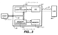
複合カード35の代表的な実施形態では、2つの別々のモジュール、すなわち1つのメモリ36と1つのI/O37とを持ち、これらはともにSDカードのフォームファクタ内に存在する。ホスト31は、メモリカードプロトコルおよびI/Oプロトコルをそれぞれ介して2つのモジュールの各々に別々にアクセスすることができる。2つの代表的な実施形態の線図が図3および5に示されている。(図3および5において、図1のカードソケット33はホスト31の一部と見なされてもよい。)
In the exemplary embodiment of
図3も、複合カード35に接続されたホスト31を示す。この実施形態では、メモリモジュール(図1の36)はメモリコントローラ101とメモリ103とからなり、I/Oモジュール(図1の37)はI/Oコントローラ105とI/Oエレメント107とからなっている。両方のコントローラ101および105がSDカードバス43に接続され、これは、米国特許出願第09/641,023号(特許文献4)により充分に記載されているように、他の特徴の中でも特に選択可能な幅を持っている。I/Oエレメント107は、通信経路41を介して外部システム39(ここでローカルエリアネットワーク(LAN)と解される)と再び通信する。前述したように、カード35上の別々のモジュール(メモリおよびI/O)は、SDカードバス43を介してホスト31と自立的に通信することができる。
FIG. 3 also shows the host 31 connected to the
始めに、メモリモジュールおよびI/Oモジュールは同じカードの一部であるけれども、これら2つのモジュールの間でデータを転送する手段が、集中的なホスト介入を通す以外には定められていない場合を考察する。この場合、モジュール間で転送されるデータの全てのビットについて、ホストを、始めにソースモジュール(メモリ/IO)から読み出し、その後それをターゲットモジュール(それぞれIO/メモリ)に書き込まなくてはならない。これは、時間を消費し、電流を引くSDカードバス動作を引き起こし、ホストをビジーに保つことになる。また、ホストが転送されるデータを緩衝記憶するのに充分なRAMメモリを持つことも必要とするが、ある用途ではそのようではない。ホストは割合に限られたRAM容量を有することができるが、ホストを通過することを必要とすることなく、将来ホストで使うためにメモリモジュールの大容量記憶メモリに大量のデータを格納するために、記載されているDMAプロセスを使用することができる。例えば、動作している他のプロセスをホストが処理している間に、インターネットから大きなファイルをI/Oモジュールを介してメモリモジュールにダウンロードすることができる。 First, the memory module and the I / O module are part of the same card, but the means for transferring data between these two modules is not defined except through intensive host intervention. Consider. In this case, for all bits of data transferred between modules, the host must first read from the source module (memory / IO) and then write it to the target module (each IO / memory). This consumes time and causes SD card bus operation that draws current and keeps the host busy. The host also needs to have enough RAM memory to buffer the data to be transferred, but this is not the case in some applications. The host can have a limited amount of RAM capacity, but to store large amounts of data in the mass storage memory of the memory module for future use by the host without having to pass through the host The described DMA process can be used. For example, a large file can be downloaded from the Internet to the memory module via the I / O module while the host is processing other running processes.
より具体的には、メモリモジュールと入出力モジュールとの間での直接メモリアクセス(DMA)なしでLAN39から情報をダウンロードし、かつそれをメモリ103の大容量フラッシュメモリに格納するために、ホスト31が複合カード35をどのように使用することができるかという場合を考察する。この事態は、2つのモジュールが単一のカードに統合されていない場合に類似している。この場合、ホスト31がI/Oプロトコルを介してLAN39からダウンロードし、かつSDメモリカードプロトコル(ここでSDプロトコル)を介して不揮発性メモリ103に格納したい情報の各々の全てのビットがホスト31によって直接処理されなければならない。特に、音楽やビデオコンテンツなどの大量のデータについて、これは特に非能率的となる。本発明の主要な態様は、このような動作におけるホストの関与を劇的に減少させるDMAメカニズムを複合カード内の2つのモジュール間に導入することである。
More specifically, in order to download information from the
SDまたは他の複合カード35においてIOモジュールおよびメモリモジュールの間にDMAメカニズムを導入することにはいくつかの利点がある。ホスト31は、単にデータ転送を開始するだけであるので、実際のデータ転送との関わりは極めて小さくてよく、従ってIOモジュールとメモリモジュールとがそれら自身の間でデータを転送している間に他のタスクを処理することができる。また、データ転送中、SDバス43はアイドルであってもよいので、電力消費量が低減される。さらに、DMAメカニズムが必要とするコマンドおよび応答処理は少ないので、データ転送は従来の方法の場合よりも速くなる。
There are several advantages to introducing a DMA mechanism between an IO module and a memory module in an SD or other
提案されているDMAメカニズムの基本的なコンセプトは、ホストにDMAデータ転送を開始させ、カードモジュール同士がそれら自身の間でデータを転送している間はDMA完了を待たせることである。SD複合カードの設計についての代表的な実施形態の2つの変形例を提示する。図3および4に関して記載されている“バスDMA”と称される第1の変形例では、2つのモジュールのコントローラは、それら自身の間に最小限のリンケージを有し、かつ両方ともにSDバスに接続される。図5および6に関して記載され、ここで“内部DMA”と称される第2の変形例では、2つの機能(メモリおよびIO)は1つのコントローラによって管理され、これはSDバスと直接インタフェースするカード側の唯一の存在である。 The basic concept of the proposed DMA mechanism is to have the host initiate DMA data transfer and wait for DMA completion while the card modules are transferring data between themselves. Two variations of an exemplary embodiment for the design of an SD composite card are presented. In the first variant, referred to as “Bus DMA”, described with respect to FIGS. 3 and 4, the two module controllers have a minimal linkage between themselves and both are on the SD bus. Connected. In a second variant described with reference to FIGS. 5 and 6, referred to herein as “internal DMA”, the two functions (memory and IO) are managed by one controller, which is a card that interfaces directly with the SD bus. Is the only existence on the side.
図3は、バスDMAの実施形態のブロック図である。SDバス43とのインタフェースを各々有する2つのコントローラ101および105がカード内にある。データはメモリ103とIO107との間でSDバス43を介して転送される。この実施形態では、ホストはクロックを供給するが、その他の点ではデータ転送に関与しない。このモードでは、DMA転送はSDシングルバスモード、ワイドバスモード或いはSPIモードで支援され得るけれども、バス幅は、米国特許出願第09/641,023号(特許文献4)により充分に記載されているように、DMA動作の前に好ましくは1ビットにセットされる。(というのは、SDカードが、DMA転送完了時に割込みを発生させるために(MMC仕様のバージョン2.11または米国特許出願第09/641,023号(特許文献4)に記載されている)DAT1を使用し、またホストがワイドバスモードで正当な割込み期間を決定するためにバス処理を追跡しなくてもよいからである。)
FIG. 3 is a block diagram of an embodiment of a bus DMA. Two
この実施形態では、LAN39からメモリ103内の不揮発性大容量メモリにデータを転送するとき、データは始めに通信経路41を介してIO107に転送される。そこから、IOコントローラ105からSDバス43を介してメモリコントローラ101へ、次いでメモリ103へ転送される。データがSDバス43を介して転送されるとき、ホストもDMA転送中にこのデータにアクセスすることができる。このプロセスは破線で概略的に示されている。ひとたびホストがカードに転送を実行するように指示すると、当該プロセスはクロック信号の供給は別としてホストから独立して実行される。メモリからの転送は、対応する逆の方法で実行される。
In this embodiment, when data is transferred from the
図4を参照すると、図3による改変されたSDカード35の中の電子システムがブロック図でより詳しい形で示されている。メモリコントローラ101は線104を介して1つ以上のメモリユニット103と通信する。コントローラ101は、マイクロプロセッサ106とそのインタフェース回路109とを備える。インタフェース回路109は、メモリ111、SDバス/ホストインタフェース回路113およびメモリインタフェース回路115に相互接続されている。メモリユニット103は、線104に接続されたコントローラインタフェース119と、フラッシュメモリまたは不揮発性大容量記憶アレイ121とを包含する。コントローラ101と各メモリユニット103とも、普通はカードのプリント回路基板に取り付けられて相互に接続された別々の集積回路チップ上に設けられるが、進歩する処理技術が可能にするようにより多くを単一のチップに結合させるのが趨勢となっている。
Referring to FIG. 4, the electronic system in the modified
バス43を介してインタフェース113に接続されている123で概略的に示されているコネクタは、カードソケット33(図1および2)に挿入されるSDカードの表面接点を備えている。コントローラ101は、メモリユニット103と、カードが接続されているホストとの間のコマンドおよびデータの流れを制御する。コントローラ101は、メモリユニット103の動作と、当該ユニットのホストとの通信とを現行のSDカードでコントローラが行っているのと実質的に同じ方法で管理する。
The connector schematically shown at 123 connected to the
IOモジュールでは、IOコントローラ105は、線145を介して1つ以上のIOユニット107と通信している。IOコントローラも、マイクロプロセッサ147と、そのインタフェース回路149とを備えている。インタフェース回路149は、メモリ151、SDバス/ホストインタフェース回路153および入出力ユニット107とインタフェースする回路155と相互接続されている。コントローラ105と各IOユニット107とも、普通はカードのプリント回路基板に取り付けられて相互に接続された別々の集積回路チップ上に設けられるが、進歩する処理技術が可能にするようにより多くを単一のチップに結合させるのが趨勢となっている。線145はコントローラインタフェース回路133に接続され、この回路はプロセッサインタフェース回路135と接続されている。入出力カードの動作を制御するマイクロプロセッサ137とメモリ139とも、プロセッサインタフェース135と接続されている。他の実装例では、IOユニット107内にマイクロプロセッサ137を持たないであろうが、その代わりに何らかの専用論理とともにI/Oコントローラ105により管理されるレジスタのセットとを有してもよい。一般に、メモリコントローラ101とI/Oコントローラ105の両方がDMAプロトコルを知っているので、特別のDMAエレメントは必要とされない。最後に、回路141も、プロセッサと、送信装置143を介して送受信される信号またはデータとの間でインタフェースするためにプロセッサインタフェース135に接続されている。有線通信が使用されるならば、装置143はプラグのためのレセプタクルである。無線周波数を使用する無線であれば、装置143はアンテナである。赤外線通信を使用する無線であれば、装置143は赤外線信号のエミッタおよび/または検出器を備える。いずれにしても、マイクロプロセッサ137は、装置143とコネクタ131との間でのデータ転送を制御する。
In the IO module, the
図5および6に関して内部DMAが示されている。単一のコントローラ101’は、IOユニット107とメモリユニット103との間のデータ転送を内部で実行する。DMA転送中、SDバス43は完全にアイドルであってよいので、電力消費量が低減される。従って、これはより効率的な方法である。ホストは内部DMA動作中に内部DMA動作で転送されているデータを読み出すことができ、その場合モジュールのうちの1つがデータのソースである。この並列性を達成するために、ホストは、ワイドバスモードの割込みを支援するべきであるか、或いは、カードが内部DMA動作完了時に割込みを発生させるためにDAT1を使用するので、DMA動作の前にカードを単一のバスモードに切り替えるべきである。(ここでも、バスモードの詳細については米国特許出願第09/641,023号(特許文献4)を参照されたい。)
Internal DMA is shown with respect to FIGS. A
内部DMA支援を有する実施形態では、LAN39からメモリ103内の不揮発性大容量記憶メモリへデータを転送するとき、データは始めにまた通信経路41を介してIO107へ転送される。しかし、今日では、SDバス43を使用せずにコントローラ101’を直接介してメモリ103へ転送される。このプロセスは点線で概略的に示されている。ひとたびホストがカードに転送を実行するように指示すると、SDバス43は(ホスト31もIOモジュールから読み出されなければ)アイドルであり、プロセスはホストとは無関係に実行される。メモリ103からLAN39への転送は、対応する逆の方法で実行される。コントローラ101’からホスト31への照明された破線は、内部DMAプロセス中の随意のデータ読み出しを示している。逆のプロセス中のデータ書き込みの場合、この矢印は他の方向に伸びる。
In an embodiment with internal DMA support, when transferring data from the
図6は、図5による改変されたSDカード35内の電子システムをより詳しい形で示す。単一のコントローラ101’は、線104を介して1つ以上のメモリユニット103と通信し、線145を介して1つ以上のIOユニット107と通信する。メモリユニット103とIOユニット107とは、図4に関連して前述されたものと同じである。コントローラ101’は、図4のメモリコントローラ101と類似し、かつマイクロプロセッサ106’も備え、そのインタフェース回路109’はメモリ111’、SDバス/ホストインタフェース回路113’およびメモリインタフェース回路115’と相互接続されている。コントローラ101’は、入出力カードとインタフェースする回路117も備えている。図4のIOコントローラ105で以前は処理されていた機能が今は複合コントローラ101’に移されているので、それらが幾分異なり得るために、図6のコントローラ101’の構成要素は図4の同様な番号の構成要素と幾分異なり得ることを示すためにプライム記号が使用されている。
FIG. 6 shows in more detail the electronic system in the modified
コントローラ101’、各メモリユニット103と各IOユニット107とも、普通はカードのプリント回路基板に取り付けられて相互に接続された別々の集積回路チップ上に設けられるが、進歩する処理技術が可能にするようにより多くを単一のチップに結合させるのが趨勢となっている。バス43を介してインタフェース113に接続されている123で概略的に示されているコネクタは、カードソケット33(図1および2)に挿入されるSDカードの表面接点を備えている。コントローラ101’は、メモリユニット103と、IOユニット107と、カードが接続されているホストとの間のコマンドおよびデータの流れを制御する。
The controller 101 ', each
一般に、所定のカードは2つのDMA方法のうちの1つだけを支援する。図3および4の実施形態は2つのコントローラを示し、図5および6の実施形態は単一のコントローラを有するけれども、実際上この分割は幾分人為的であり、種々の機能は種々の方法でカードのいろいろなチップ間に分配されてもよい。複数のエレメントが単一のチップ上で結合されるので、コントローラ間の分割はなおさら取り決めの問題となる。バスDMAと内部DMAプロセスとを原理的に区別する特徴は、IOモジュールと大容量記憶モジュールとの間で使用される経路であり、すなわち代表的な実施形態ではSDバスが使用されるか否かである。 In general, a given card supports only one of two DMA methods. Although the embodiments of FIGS. 3 and 4 show two controllers and the embodiments of FIGS. 5 and 6 have a single controller, in practice this division is somewhat artificial and the various functions can be performed in various ways. It may be distributed among the various chips of the card. Since multiple elements are combined on a single chip, partitioning between controllers is still a matter of agreement. A feature that distinguishes in principle between bus DMA and internal DMA processes is the path used between the IO module and the mass storage module, i.e. whether the SD bus is used in the exemplary embodiment. It is.
代表的なSDカードの実施形態内での実装例を今からより詳しく説明する。検討を具体的にするために、“マルチメディアカードシステムの仕様”バージョン2.11および2.2と、米国特許出願第09/185,649号(特許文献1)、第09/186,064号(特許文献2)および第09/641,023号(特許文献4)とにおいてより充分に説明されている種々のコマンド、構造およびレジスタに言及する。これら特許出願の全ては、本願明細書において参照により前に援用されている。 An example implementation within a typical SD card embodiment will now be described in more detail. To make the study concrete, "Multimedia Card System Specifications" versions 2.11 and 2.2, US patent application Ser. Nos. 09 / 185,649, and 09 / 186,064. Reference is made to various commands, structures, and registers that are more fully described in US Pat. All of these patent applications have been previously incorporated herein by reference.
DMA支援を示すために、DMA方法の判定のために2ビットをカード制御レジスタに割り当てることができる。例えば、これらのビットの‘00’の値はDMA支援なしを、‘01’はバスDMAを、‘10’は内部DMAを意味することができる。ホストは、これらのビットを1回読み出すだけでよくて、それを当該カードでの次の全てのDMA処理に適用する。 To indicate DMA support, two bits can be assigned to the card control register for DMA method determination. For example, the value of “00” of these bits may mean no DMA support, “01” may mean bus DMA, and “10” may mean internal DMA. The host need only read these bits once and apply it to all subsequent DMA processing on the card.
SDカードコマンド構造内で、DMAプロセスのために新しいコマンドDMA_CMDが定義される。ホストは、DMA動作を起動したいときに、それを使用しなければならない。1つの代表的なコマンド構造は、図8のテーブルである。当該テーブルの第1の行は第2の行の各項目に割り当てられるビットの数であり、それらはこの例では次のように定義される。
S(tart bit):開始ビット。常に‘0’。
D(irection):方向。常に‘1’であり、ホストからカードへの転送を示す。
DMA方向:‘1’はデータがIOからメモリへ転送されることを意味し、‘0’はデータがメモリからIOへ転送されることを意味する。
IO機能番号:ホストがメモリモジュールに対して読み書きすることを望むIOモジュール内の機能の番号。
OPコード:IOアドレスを‘0’−固定アドレス、‘1’−増分するアドレスと定義する。
IOレジスタアドレス:読み出しまたは書き込むためのIOレジスタの開始アドレス。
ブロックカウント:DMA動作で転送されるべきデータブロックの数。
スタッフビット:常に‘0’であり、何の意味も持たない。
CRC7:コマンドの循環冗長検査(CRC)の7ビット。
E(nd bit):エンドビット。常に‘1’。
SDまたはMMCコマンド構造では、カードが転送状態でホストからデータ処理コマンドを入手する準備が整っているときに、コマンドは正当であり、その後カードはモードの適切な応答で答える。
Within the SD card command structure, a new command DMA_CMD is defined for the DMA process. The host must use it when it wants to initiate a DMA operation. One representative command structure is the table of FIG. The first row of the table is the number of bits assigned to each item in the second row, which in this example is defined as:
S (target bit): Start bit. Always '0'.
D (direction): direction. Always '1', indicating transfer from host to card.
DMA direction: '1' means that data is transferred from IO to memory, and '0' means that data is transferred from memory to IO.
IO function number: The number of the function in the IO module that the host wants to read from or write to the memory module.
OP code: IO address is defined as “0” —fixed address, “1” —increment address
IO register address: Start address of the IO register for reading or writing.
Block count: The number of data blocks to be transferred in a DMA operation.
Stuff bit: Always “0”, meaning nothing.
CRC7: 7 bits of cyclic redundancy check (CRC) of command.
E (nd bit): End bit. Always '1'.
In the SD or MMC command structure, the command is valid when the card is ready to get a data processing command from the host in the transfer state, and then the card responds with an appropriate response for the mode.
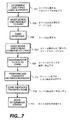
図7は、本発明のDMA動作を説明するフローチャートである。ステップ701で、ホストは、DMA方法が支援されるか否か、また支援されるとすればどんなDMA方法が支援されるのかを判定するためにカード制御レジスタのDMA指示ビットを読み出す。カードは両方のDMAモードを支援することができるけれども、好ましい実施形態はカードあたりに単一モードに制限される。というのは、これが仕様および実装例の両方を簡略化するからである。ステップ703で、ホストはDMAコマンドDMA_CMDをカードに送る。これは、DMA方向(メモリモジュールからIO機能へ転送が要求されるならば‘0’に等しく、その逆ならば‘1’に等しい)と、要求されているIO機能にセットされたIO機能番号、OPコード(IOアドレスが固定されているならば‘0’に等しく、増分しているならば‘1’に等しい)、IOレジスタアドレス(開始IOレジスタアドレスを反映するようにセットされる)およびブロックカウントを含む。ブロックカウントはデータブロックの数を反映するようにセットされ、そのサイズは、SD/MMCコマンド構造においてメモリについてはCMD16を通して、IOについてはCMD52/53を通して前もってセットされる。
FIG. 7 is a flowchart for explaining the DMA operation of the present invention. In
ステップ705で、カードはDMA_CMDに応答する。何か問題があれば(例えば、無効なコマンド)、流れは終了する。ステップ707で、ホストは書き込み/読み出しコマンドをメモリモジュール(SD/MMCコマンド構造ではCMD17/18または24/25)に送る。DMAタイプに基づいて、ホストは、自らが転送中にどんな信号をカードに供給する必要があるのかを判定する。例えば、当該方法がバスDMAであれば、ホストはクロック信号をSDバスに供給し続けるが、そうでなければ、クロックを止めることができる。
In
ステップ711で2つのモジュールはそれら自身の間でデータを転送し、ステップ713でカードはプロセスが完了したことを表示する。SDカードの場合、DMA動作が完了すると、カードはDAT1線上に割込みを発生させる(‘0’にアサートする)。最後に、ステップ715で、ホストは通常のメモリおよびIO状況(SD/MMCコマンド構造におけるCMD13およびCMD52)を読み出して完了状況を判定する。
In
SDカードコマンド構造に基づくバスDMAの実施形態では、循環冗長検査(CRC)、CRC応答およびビジー表示に関しての当該2つのモジュール間の接続手順は、通常動作におけるホストおよびカード間の接続手順と同じである。ソースモジュールはデータをデータ線で表示し、これにCRC16およびエンドビットが続く。ターゲットモジュールはCRC応答とビジー表示とで応答する。全てのバスタイミングの定義は、正規のSDバスタイミングに従う。 In the embodiment of the bus DMA based on the SD card command structure, the connection procedure between the two modules regarding cyclic redundancy check (CRC), CRC response and busy display is the same as the connection procedure between the host and the card in normal operation. is there. The source module displays the data with data lines, followed by CRC16 and an end bit. The target module responds with a CRC response and a busy indication. All bus timing definitions follow regular SD bus timing.
前述したように、本発明をSDカードの実施形態の文脈で記載したが、本発明はあらゆる複合メモリ/IOカードにも及ぶ。例えば、本発明は、スマートカードコントローラを収容するカードなどの内部ファイルシステムを使用する複合カード規格に拡張され得る。このようなシステムでは、ホストはファイルのチャンク(例えば、動作システムのためのディスククラスタまたはその他の適切なユニット)毎にDMA転送を開始することを必要とせずにファイル全体のために1つのDMA動作を指定することができるので、ホストの関与を大幅に減少させることができる。 As described above, the invention has been described in the context of an SD card embodiment, but the invention extends to any composite memory / IO card. For example, the present invention can be extended to a composite card standard that uses an internal file system such as a card that houses a smart card controller. In such a system, the host does one DMA operation for the entire file without having to initiate a DMA transfer for each chunk of file (eg, disk cluster or other suitable unit for the operating system). Can be specified, so that the involvement of the host can be greatly reduced.
本発明の種々の態様を特定の実施形態に関連して説明してきたが、本発明が添付の特許請求の範囲全体の中でその権利が保護されるべきことが理解されよう。 While various aspects of the invention have been described with reference to specific embodiments, it will be understood that the invention is entitled to protection within the full scope of the appended claims.
Claims (47)
不揮発性大容量データ記憶装置部分を含むメモリモジュールと、
前記カードと外部装置との間でデータを伝達する入出力モジュールであって、前記カードが接続されるホストからのコマンドに応じて、前記カードは前記入出力モジュールと前記大容量データ記憶装置部分との間の前記データの直接メモリアクセス形転送を用いて前記外部装置と前記不揮発性大容量データメモリとの間でデータ転送を実行するものである入出力モジュールと、
を備えることを特徴とするカード。 In an electronic circuit card that can be connected to a host system,
A memory module including a nonvolatile mass data storage device portion;
An input / output module for transmitting data between the card and an external device, wherein the card is connected to the input / output module and the mass data storage device according to a command from a host to which the card is connected An input / output module that performs data transfer between the external device and the non-volatile mass data memory using direct memory access transfer of the data between;
A card characterized by comprising:
バス構造であって、前記バス構造によってデータおよびコマンドが前記ホストとカードとの間で交換され、前記メモリコントローラと前記入出力コントローラとはともに前記バス構造に独立して接続され、前記直接メモリアクセス形転送は前記バス構造を用いて実行されるものであるバス構造と、
をさらに備えることを特徴とする請求項1記載のカード。 The memory module further comprises a memory controller, the input / output module further comprises an input / output controller, and the card is
A bus structure in which data and commands are exchanged between the host and the card by the bus structure, and the memory controller and the input / output controller are both independently connected to the bus structure, and the direct memory access A form transfer is performed using the bus structure;
The card according to claim 1, further comprising:
バス構造であって、前記バス構造によってデータおよびコマンドが前記ホストとカードとの間で交換され、前記複合コントローラは前記バス構造に接続され、前記直接メモリアクセス形転送は前記バス構造を用いずに実行されるものであるバス構造と、
をさらに備えることを特徴とする請求項1記載のカード。 The memory module further includes a composite memory / input / output controller, and the card includes:
A bus structure in which data and commands are exchanged between the host and the card by the bus structure, the composite controller is connected to the bus structure, and the direct memory access type transfer is performed without using the bus structure. A bus structure that is to be executed, and
The card according to claim 1, further comprising:
ホストと、
外部通信装置と、
ホストシステムに接続可能な電子回路カードであって、前記カードは、
不揮発性大容量データ記憶装置部分を含むメモリモジュールと、
前記カードと前記外部装置との間でデータを伝達する入出力モジュールであって、前記ホストからのコマンドに応じて、前記カードは前記入出力モジュールと前記大容量データ記憶装置部分との間の前記データの直接メモリアクセス形転送を用いて前記外部装置とメモリとの間でデータ転送を実行するものである入出力モジュールと、を備える電子回路カードと、
を備えることを特徴とするシステム。 In the system,
A host,
An external communication device;
An electronic circuit card connectable to a host system, wherein the card is
A memory module including a nonvolatile mass data storage device portion;
An input / output module for transmitting data between the card and the external device, wherein the card is connected between the input / output module and the mass data storage device in response to a command from the host. An electronic circuit card comprising: an input / output module that performs data transfer between the external device and the memory using direct memory access transfer of data;
A system comprising:
バス構造であって、前記バス構造によってデータおよびコマンドが前記ホストとカードとの間で交換され、前記メモリコントローラと前記入出力コントローラとはともに前記バス構造に独立して接続され、前記直接メモリアクセス形転送は前記バス構造を用いて実行されるものであるバス構造と、
をさらに備えることを特徴とする請求項11記載のシステム。 The memory module further comprises a memory controller, the input / output module further comprises an input / output controller, and the card is
A bus structure in which data and commands are exchanged between the host and the card by the bus structure, and the memory controller and the input / output controller are both independently connected to the bus structure, and the direct memory access A form transfer is performed using the bus structure;
The system of claim 11, further comprising:
バス構造であって、前記バス構造によってデータおよびコマンドが前記ホストとカードとの間で交換され、前記複合コントローラは前記バス構造に接続され、前記直接メモリアクセス形転送は前記バス構造を用いずに実行されるものであるバス構造と、
をさらに備えることを特徴とする請求項11記載のシステム。 The memory module further includes a composite memory / input / output controller, and the card includes:
A bus structure in which data and commands are exchanged between the host and the card by the bus structure, the composite controller is connected to the bus structure, and the direct memory access type transfer is performed without using the bus structure. A bus structure that is to be executed, and
The system of claim 11, further comprising:
不揮発性大容量データ記憶装置部分を含むメモリモジュールと、
前記ホストカードシステムから外部的にデータを受け取りかつ/または前記ホストカードシステムへ外部的にデータを送ることを含む外部データ転送を実行する入出力モジュールであって、前記カードが接続されるホストからのコマンドに応じて、前記カードは前記入出力モジュールと前記大容量データ記憶装置部分との間の前記データの直接メモリアクセス形転送を用いて前記不揮発性大容量データ記憶装置部分との外部データ転送を実行するものである入出力モジュールと、
を備えることを特徴とするカード。 In an electronic circuit card that can be connected to a host system,
A memory module including a nonvolatile mass data storage device portion;
An input / output module for performing external data transfer, including receiving data externally from the host card system and / or transmitting data externally to the host card system, from the host to which the card is connected In response to a command, the card performs external data transfer with the nonvolatile mass data storage unit using direct memory access type transfer of the data between the input / output module and the mass data storage unit. An input / output module to be executed;
A card characterized by comprising:
バス構造であって、前記バス構造によってデータおよびコマンドが前記ホストとカードとの間で交換され、前記メモリコントローラと前記入出力コントローラとはともに前記バス構造に独立して接続され、前記直接メモリアクセス形転送は前記バス構造を用いて実行されるものであるバス構造と、
をさらに備えることを特徴とする請求項28記載のカード。 The memory module further comprises a memory controller, the input / output module further comprises an input / output controller, and the card is
A bus structure in which data and commands are exchanged between the host and the card by the bus structure, and the memory controller and the input / output controller are both independently connected to the bus structure, and the direct memory access A form transfer is performed using the bus structure;
The card of claim 28, further comprising:
バス構造であって、前記バス構造によってデータおよびコマンドが前記ホストとカードとの間で交換され、前記複合コントローラは前記バス構造に接続され、前記直接メモリアクセス形転送は前記バス構造を用いずに実行されるものであるバス構造と、
をさらに備えることを特徴とする請求項28記載のカード。 The memory module further includes a composite memory / input / output controller, and the card includes:
A bus structure in which data and commands are exchanged between the host and the card by the bus structure, the composite controller is connected to the bus structure, and the direct memory access type transfer is performed without using the bus structure. A bus structure that is to be executed, and
The card of claim 28, further comprising:
ホストと、
ホストシステムに接続可能な電子回路カードであって、前記カードは、
不揮発性大容量データ記憶装置部分を含むメモリモジュールと、
前記システムから外部的にデータを受け取りかつ/または前記システムへ外部的にデータを送ることを含む外部データ転送を実行する入出力モジュールであって、前記ホストからのコマンドに応じて、前記カードは前記入出力モジュールと前記大容量データ記憶装置部分との間の前記データの直接メモリアクセス形転送を用いて前記不揮発性大容量データ記憶装置部分との外部データ転送を実行するものである入出力モジュールと、を備える電子回路カードと、
を備えることを特徴とするシステム。 In the system,
A host,
An electronic circuit card connectable to a host system, wherein the card is
A memory module including a nonvolatile mass data storage device portion;
An input / output module that performs external data transfer including receiving data externally from the system and / or sending data externally to the system, wherein the card is responsive to a command from the host An input / output module for performing external data transfer with the non-volatile mass data storage device portion using direct memory access type transfer of the data between the entry output module and the mass data storage device portion; An electronic circuit card comprising:
A system comprising:
バス構造であって、前記バス構造によってデータおよびコマンドが前記ホストとカードとの間で交換され、前記メモリコントローラと前記入出力コントローラとはともに前記バス構造に独立して接続され、前記直接メモリアクセス形転送は前記バス構造を用いて実行されるものであるバス構造と、
をさらに備えることを特徴とする請求項37記載のシステム。 The memory module further comprises a memory controller, the input / output module further comprises an input / output controller, and the card is
A bus structure in which data and commands are exchanged between the host and the card by the bus structure, and the memory controller and the input / output controller are both independently connected to the bus structure, and the direct memory access A form transfer is performed using the bus structure;
38. The system of claim 37, further comprising:
バス構造であって、前記バス構造によってデータおよびコマンドが前記ホストとカードとの間で交換され、前記複合コントローラは前記バス構造に接続され、前記直接メモリアクセス形転送は前記バス構造を用いずに実行されるものであるバス構造と、
をさらに備えることを特徴とする請求項37記載のシステム。 The memory module further includes a composite memory / input / output controller, and the card includes:
A bus structure in which data and commands are exchanged between the host and the card by the bus structure, the composite controller is connected to the bus structure, and the direct memory access type transfer is performed without using the bus structure. A bus structure that is to be executed, and
38. The system of claim 37, further comprising:
Applications Claiming Priority (2)
| Application Number | Priority Date | Filing Date | Title |
|---|---|---|---|
| US10/302,009 US8037229B2 (en) | 2002-11-21 | 2002-11-21 | Combination non-volatile memory and input-output card with direct memory access |
| PCT/US2003/040042 WO2004049177A2 (en) | 2002-11-21 | 2003-11-20 | Combination non-volatile memory and input-output card with direct memory access |
Publications (2)
| Publication Number | Publication Date |
|---|---|
| JP2006507608A true JP2006507608A (en) | 2006-03-02 |
| JP2006507608A5 JP2006507608A5 (en) | 2006-11-30 |
Family
ID=32324651
Family Applications (1)
| Application Number | Title | Priority Date | Filing Date |
|---|---|---|---|
| JP2004555838A Pending JP2006507608A (en) | 2002-11-21 | 2003-11-20 | Composite non-volatile memory / input / output card with direct memory access |
Country Status (8)
| Country | Link |
|---|---|
| US (2) | US8037229B2 (en) |
| EP (1) | EP1563391A2 (en) |
| JP (1) | JP2006507608A (en) |
| KR (1) | KR20050110609A (en) |
| CN (1) | CN1732449A (en) |
| AU (1) | AU2003300968A1 (en) |
| TW (1) | TW200413937A (en) |
| WO (1) | WO2004049177A2 (en) |
Cited By (7)
| Publication number | Priority date | Publication date | Assignee | Title |
|---|---|---|---|---|
| JP2008545186A (en) * | 2005-07-01 | 2008-12-11 | ボラーチ,ファブリジオ | General-purpose smart card |
| JP2012168866A (en) * | 2011-02-16 | 2012-09-06 | Toshiba Corp | Memory system |
| JP2012181611A (en) * | 2011-02-28 | 2012-09-20 | Toshiba Corp | Memory system |
| JP2013222244A (en) * | 2012-04-13 | 2013-10-28 | Toshiba Corp | Memory device and radio communication control method thereof |
| WO2014006731A1 (en) * | 2012-07-05 | 2014-01-09 | 富士通株式会社 | Data backup method and interface card |
| JP2014032695A (en) * | 2013-10-15 | 2014-02-20 | Canon Inc | Information processing apparatus, method for controlling information processing apparatus, and program |
| US10432035B2 (en) | 2015-04-28 | 2019-10-01 | Toshiba Memory Corporation | Wireless communication device, method for controlling wireless communication device, game system, and memory system |
Families Citing this family (63)
| Publication number | Priority date | Publication date | Assignee | Title |
|---|---|---|---|---|
| US7107378B1 (en) * | 2000-09-01 | 2006-09-12 | Sandisk Corporation | Cooperative interconnection and operation of a non-volatile memory card and an input-output card |
| US7554842B2 (en) * | 2001-09-17 | 2009-06-30 | Sandisk Corporation | Multi-purpose non-volatile memory card |
| US7440774B2 (en) * | 2002-04-08 | 2008-10-21 | Socket Mobile, Inc. | Wireless enabled memory module |
| GB2394152B (en) * | 2002-10-09 | 2005-11-02 | Nokia Corp | DMA Detection |
| US7367503B2 (en) | 2002-11-13 | 2008-05-06 | Sandisk Corporation | Universal non-volatile memory card used with various different standard cards containing a memory controller |
| US8037229B2 (en) | 2002-11-21 | 2011-10-11 | Sandisk Technologies Inc. | Combination non-volatile memory and input-output card with direct memory access |
| US20050055479A1 (en) * | 2002-11-21 | 2005-03-10 | Aviad Zer | Multi-module circuit card with inter-module direct memory access |
| US20040196375A1 (en) * | 2003-04-03 | 2004-10-07 | Eastman Kodak Company | Compact wireless storage |
| US7305535B2 (en) | 2003-04-17 | 2007-12-04 | Sandisk Corporation | Memory cards including a standard security function |
| WO2004107678A2 (en) * | 2003-05-28 | 2004-12-09 | Artimi Ltd | Ultra-wideband network, device, device controller, method and data packet for establishing a mesh network and forwarding packets on another channel |
| US7673066B2 (en) * | 2003-11-07 | 2010-03-02 | Sony Corporation | File transfer protocol for mobile computer |
| US7209995B2 (en) * | 2003-12-09 | 2007-04-24 | Sandisk Corporation | Efficient connection between modules of removable electronic circuit cards |
| US7814377B2 (en) | 2004-07-09 | 2010-10-12 | Sandisk Corporation | Non-volatile memory system with self test capability |
| FI116255B (en) | 2004-07-12 | 2005-10-14 | Suunto Oy | Receiver and data transfer method |
| KR100602278B1 (en) | 2004-12-28 | 2006-07-18 | 엘지전자 주식회사 | Flash memory |
| CN1317655C (en) * | 2004-12-31 | 2007-05-23 | 北京中星微电子有限公司 | DMA transmission method adapted for SD cards |
| KR100837268B1 (en) * | 2005-02-03 | 2008-06-11 | 삼성전자주식회사 | Apparatus and method for controlling the power down mode in memory card |
| US20060255160A1 (en) * | 2005-05-13 | 2006-11-16 | Otto Winkler | Memory card, the fabrication thereof and a mobile phone apparatus having a memory card |
| US7763004B2 (en) * | 2005-05-18 | 2010-07-27 | The Procter & Gamble Company | Disposable absorbent article having layered containment pockets |
| JP5430050B2 (en) | 2005-06-24 | 2014-02-26 | フェリカネットワークス株式会社 | Data communication system, device for executing IC card function, control method therefor, and information processing terminal |
| US7631245B2 (en) * | 2005-09-26 | 2009-12-08 | Sandisk Il Ltd. | NAND flash memory controller exporting a NAND interface |
| US8291295B2 (en) * | 2005-09-26 | 2012-10-16 | Sandisk Il Ltd. | NAND flash memory controller exporting a NAND interface |
| US7697827B2 (en) | 2005-10-17 | 2010-04-13 | Konicek Jeffrey C | User-friendlier interfaces for a camera |
| US20070145135A1 (en) * | 2005-12-28 | 2007-06-28 | Fabrice Jogand-Coulomb | Methods used in a nested memory system with near field communications capability |
| KR101425181B1 (en) * | 2006-05-29 | 2014-08-01 | 서트게이트 게엠베하 | Method for communication with a multi-function memory card |
| US20080046641A1 (en) * | 2006-08-21 | 2008-02-21 | Sandisk Il Ltd. | NAND flash memory controller exporting a logical sector-based interface |
| US20080046630A1 (en) * | 2006-08-21 | 2008-02-21 | Sandisk Il Ltd. | NAND flash memory controller exporting a logical sector-based interface |
| US8156272B2 (en) * | 2006-09-01 | 2012-04-10 | Spansion Llc | Multiple communication channels on MMC or SD CMD line |
| JP4956143B2 (en) * | 2006-11-02 | 2012-06-20 | 株式会社東芝 | Semiconductor memory card, host device, and data transfer method |
| US8079071B2 (en) | 2006-11-14 | 2011-12-13 | SanDisk Technologies, Inc. | Methods for accessing content based on a session ticket |
| US20080114693A1 (en) * | 2006-11-14 | 2008-05-15 | Fabrice Jogand-Coulomb | Method for allowing content protected by a first DRM system to be accessed by a second DRM system |
| US20080114772A1 (en) * | 2006-11-14 | 2008-05-15 | Fabrice Jogand-Coulomb | Method for connecting to a network location associated with content |
| US8327454B2 (en) * | 2006-11-14 | 2012-12-04 | Sandisk Technologies Inc. | Method for allowing multiple users to access preview content |
| US8763110B2 (en) * | 2006-11-14 | 2014-06-24 | Sandisk Technologies Inc. | Apparatuses for binding content to a separate memory device |
| US20080112562A1 (en) * | 2006-11-14 | 2008-05-15 | Fabrice Jogand-Coulomb | Methods for linking content with license |
| KR100866625B1 (en) | 2007-02-26 | 2008-11-03 | 삼성전자주식회사 | Method and system for interfacing a plurality of memory devices using MMC or SD protocol |
| US8762640B2 (en) * | 2007-06-27 | 2014-06-24 | Sandisk Il Ltd. | Method for operating a memory interface with SIM functions |
| US7827352B2 (en) * | 2007-09-18 | 2010-11-02 | Intel Corporation | Loading data from a memory card |
| US7886103B2 (en) * | 2008-09-08 | 2011-02-08 | Cisco Technology, Inc. | Input-output module, processing platform and method for extending a memory interface for input-output operations |
| US8316201B2 (en) * | 2008-12-18 | 2012-11-20 | Sandisk Il Ltd. | Methods for executing a command to write data from a source location to a destination location in a memory device |
| US20100161932A1 (en) * | 2008-12-18 | 2010-06-24 | Ori Moshe Stern | Methods for writing data from a source location to a destination location in a memory device |
| EP2391945B1 (en) | 2009-01-29 | 2016-01-20 | Ivy Biomedical Systems, Inc. | Interface device for communication between a medical device and a computer |
| KR101573791B1 (en) * | 2009-06-10 | 2015-12-02 | 삼성전자주식회사 | Method and apparatus for transferring data using Universal Serial Bus |
| US20110010497A1 (en) * | 2009-07-09 | 2011-01-13 | Sandisk Il Ltd. | A storage device receiving commands and data regardless of a host |
| US20110040924A1 (en) * | 2009-08-11 | 2011-02-17 | Selinger Robert D | Controller and Method for Detecting a Transmission Error Over a NAND Interface Using Error Detection Code |
| US20110041005A1 (en) * | 2009-08-11 | 2011-02-17 | Selinger Robert D | Controller and Method for Providing Read Status and Spare Block Management Information in a Flash Memory System |
| JP2011048756A (en) * | 2009-08-28 | 2011-03-10 | Toshiba Corp | Memory module |
| JP2011096090A (en) * | 2009-10-30 | 2011-05-12 | Sony Corp | Radio communication device, method of responding to host apparatus and program |
| US8595411B2 (en) | 2009-12-30 | 2013-11-26 | Sandisk Technologies Inc. | Method and controller for performing a sequence of commands |
| US8443263B2 (en) | 2009-12-30 | 2013-05-14 | Sandisk Technologies Inc. | Method and controller for performing a copy-back operation |
| JP5641754B2 (en) * | 2010-03-23 | 2014-12-17 | dブロード株式会社 | Interface card system |
| JP2012168865A (en) * | 2011-02-16 | 2012-09-06 | Toshiba Corp | Memory system |
| TWI497305B (en) * | 2012-04-05 | 2015-08-21 | ?memory card adapter device | |
| US20150026397A1 (en) * | 2013-07-20 | 2015-01-22 | Samsung Electronics, Ltd. | Method and system for providing memory module intercommunication |
| CN103631452B (en) * | 2013-11-29 | 2017-03-01 | 广州视睿电子科技有限公司 | The scan controller of infrared touch panel, controller and control method |
| US10353633B2 (en) * | 2013-12-19 | 2019-07-16 | Sony Interactive Entertainment LLC | Mass storage virtualization for cloud computing |
| US9177654B2 (en) | 2014-03-26 | 2015-11-03 | Burst Corporation | Solid-state memory device with plurality of memory cards |
| US9753503B2 (en) | 2014-08-14 | 2017-09-05 | Samsung Electronics Co., Ltd. | Memory card socket and data processing device including the same |
| TWI550620B (en) * | 2015-01-08 | 2016-09-21 | 矽統科技股份有限公司 | Integrated framework of memory storage module and sensor module |
| CN105825888B (en) * | 2015-01-08 | 2019-11-05 | 矽统科技股份有限公司 | The assembling structure of memory memory module and sensor module |
| US20170163312A1 (en) * | 2015-12-03 | 2017-06-08 | Samsung Electronics Co., Ltd. | Electronic system with network operation mechanism and method of operation thereof |
| JP2018073438A (en) * | 2016-10-24 | 2018-05-10 | 東芝メモリ株式会社 | Semiconductor memory device |
| JP2021163997A (en) * | 2020-03-30 | 2021-10-11 | キヤノン株式会社 | Imaging apparatus, device, communication method and program |
Citations (3)
| Publication number | Priority date | Publication date | Assignee | Title |
|---|---|---|---|---|
| JPH08130702A (en) * | 1994-11-02 | 1996-05-21 | Sony Corp | Digital electronic still camera |
| WO2002019266A2 (en) * | 2000-09-01 | 2002-03-07 | Sandisk Corporation | Cooperative interconnection and operation of a non-volatile memory card and an input-output card |
| JP2002329180A (en) * | 2001-04-27 | 2002-11-15 | Toshiba Corp | Memory card having radio communication function and its data communication method |
Family Cites Families (122)
| Publication number | Priority date | Publication date | Assignee | Title |
|---|---|---|---|---|
| JPS5248440A (en) * | 1975-10-15 | 1977-04-18 | Toshiba Corp | Memory access control system |
| JPS5793422A (en) * | 1980-11-29 | 1982-06-10 | Omron Tateisi Electronics Co | Dma controller |
| JPH0631959B2 (en) * | 1983-09-28 | 1994-04-27 | 沖電気工業株式会社 | Music equipment |
| JPS6279375A (en) | 1985-10-02 | 1987-04-11 | Seiko Instr & Electronics Ltd | Evaluation of insulation film |
| US4882476A (en) * | 1986-09-10 | 1989-11-21 | Norand Corporation | Bar code reader with enhanced sensitivity |
| JPH0821013B2 (en) * | 1987-05-13 | 1996-03-04 | 株式会社日立製作所 | Direct memory access order competition control method |
| US4882473A (en) * | 1987-09-18 | 1989-11-21 | Gtech Corporation | On-line wagering system with programmable game entry cards and operator security cards |
| US5155663A (en) * | 1990-02-19 | 1992-10-13 | Fuji Photo Film Co., Ltd. | Memory cartridge system with adapter |
| DE4040296C1 (en) | 1990-12-17 | 1992-01-09 | Orga Kartensysteme Gmbh, 6072 Dreieich, De | |
| DE4132720A1 (en) * | 1991-10-01 | 1993-04-08 | Gao Ges Automation Org | CHIP CARD AND METHOD FOR THE PRODUCTION THEREOF |
| FR2686172B1 (en) * | 1992-01-14 | 1996-09-06 | Gemplus Card Int | PLUG - IN CARD FOR A MICROCOMPUTER FORMING A CARD READER WITH FLUSHED CONTACTS. |
| JP3195052B2 (en) | 1992-06-25 | 2001-08-06 | ローム株式会社 | Power supply switching circuit |
| FR2693575B1 (en) * | 1992-07-09 | 1994-08-19 | Gemplus Card Int | Mass memory card with input / output function. |
| US5434872A (en) * | 1992-07-28 | 1995-07-18 | 3Com Corporation | Apparatus for automatic initiation of data transmission |
| US6665190B2 (en) | 1992-09-16 | 2003-12-16 | James E. Clayton | Modular PC card which receives add-in PC card modules |
| JPH06105271A (en) * | 1992-09-16 | 1994-04-15 | Asahi Optical Co Ltd | Ic memory card camera system |
| EP0595021A1 (en) * | 1992-10-28 | 1994-05-04 | International Business Machines Corporation | Improved lead frame package for electronic devices |
| CA2083017C (en) * | 1992-11-16 | 1999-02-09 | Alan Walter Ainsbury | Tandem circuit cards |
| EP0698247B1 (en) * | 1993-05-14 | 1998-09-02 | AMPHENOL-TUCHEL ELECTRONICS GmbH | Smt reader for sim and standard cards |
| US5887145A (en) * | 1993-09-01 | 1999-03-23 | Sandisk Corporation | Removable mother/daughter peripheral card |
| US7137011B1 (en) * | 1993-09-01 | 2006-11-14 | Sandisk Corporation | Removable mother/daughter peripheral card |
| NL9301540A (en) | 1993-09-06 | 1995-04-03 | Nedap Nv | Chipcard with more than one chip and combined I/O line |
| FR2710996B1 (en) * | 1993-10-06 | 1995-12-01 | Gemplus Card Int | Multi-application portable card for personal computer. |
| US5375084A (en) * | 1993-11-08 | 1994-12-20 | International Business Machines Corporation | Selectable interface between memory controller and memory simms |
| US6457647B1 (en) * | 1993-11-16 | 2002-10-01 | Canon Kabushiki Kaisha | Memory card adaptor to facilitate upgrades and the like |
| US5457601A (en) * | 1993-12-08 | 1995-10-10 | At&T Corp. | Credit card-sized modem with modular DAA |
| DE4416583C1 (en) | 1994-05-11 | 1995-12-07 | Angewandte Digital Elektronik | Chip card bus for connecting different card chips |
| JPH0895687A (en) * | 1994-09-26 | 1996-04-12 | Fujitsu Ltd | I/o card, connecting cable to be connected with the i/o card and power saving method for i/o card |
| JP3213872B2 (en) * | 1994-12-28 | 2001-10-02 | モレックス インコーポレーテッド | Telephone information card drive for mobile phone |
| JPH08254050A (en) * | 1995-03-17 | 1996-10-01 | Toshiba Corp | Room entering and leaving managing device |
| DE29505678U1 (en) * | 1995-04-01 | 1995-06-14 | Stocko Metallwarenfab Henkels | Contact unit for card-shaped carrier elements |
| US5742910A (en) * | 1995-05-23 | 1998-04-21 | Mci Corporation | Teleadministration of subscriber ID modules |
| DE29509736U1 (en) * | 1995-06-14 | 1996-04-04 | Giesecke & Devrient Gmbh | Standard card with embedded mini chip card |
| JPH0916735A (en) | 1995-06-26 | 1997-01-17 | Mitsubishi Electric Corp | Pc card |
| US5852290A (en) * | 1995-08-04 | 1998-12-22 | Thomson Consumer Electronics, Inc. | Smart-card based access control system with improved security |
| US5606559A (en) * | 1995-08-11 | 1997-02-25 | International Business Machines Corporation | System and method for an efficient ATM adapter/device driver interface |
| FR2738367B1 (en) * | 1995-09-05 | 1997-10-17 | Scm Microsystems | METHOD AND APPARATUS FOR FAST DOWNLOADING OF FUNCTIONS IN A VOLATILE MEMORY |
| DE29518707U1 (en) * | 1995-11-25 | 1996-01-18 | Stocko Metallwarenfab Henkels | Contact unit for card-shaped carrier elements of electronic assemblies |
| JPH09179802A (en) * | 1995-12-27 | 1997-07-11 | Mitsubishi Electric Corp | Multi function type pc card |
| FR2745402A1 (en) * | 1996-02-28 | 1997-08-29 | Philips Electronics Nv | READER OF ELECTRONIC CARDS OF DIFFERENT FORMATS AND PORTABLE TELEPHONE INCORPORATING SUCH A READER |
| IT240061Y1 (en) * | 1996-03-01 | 2001-03-26 | Cruciani Andrea | ADAPTER |
| US5784633A (en) * | 1996-03-12 | 1998-07-21 | International Business Machines Corporation | System for obtaining status data unrelated to user data path from a modem and providing control data to the modem without interrupting user data flow |
| DE29607253U1 (en) * | 1996-04-22 | 1996-07-04 | Stocko Metallwarenfab Henkels | Combi chip card reader |
| US5733800A (en) * | 1996-05-21 | 1998-03-31 | Micron Technology, Inc. | Underfill coating for LOC package |
| US5752857A (en) * | 1996-05-24 | 1998-05-19 | Itt Corporation | Smart card computer adaptor |
| JPH09321165A (en) * | 1996-05-27 | 1997-12-12 | Toshiba Corp | Semiconductor device substrate, semiconductor device, card type module and information memory |
| JPH09327990A (en) * | 1996-06-11 | 1997-12-22 | Toshiba Corp | Card type storing device |
| US5764896A (en) * | 1996-06-28 | 1998-06-09 | Compaq Computer Corporation | Method and system for reducing transfer latency when transferring data from a network to a computer system |
| DE69706991T2 (en) * | 1996-07-19 | 2002-04-25 | Tokyo Electron Device Ltd | FLASH MEMORY CARD |
| US5815426A (en) * | 1996-08-13 | 1998-09-29 | Nexcom Technology, Inc. | Adapter for interfacing an insertable/removable digital memory apparatus to a host data part |
| US6134631A (en) * | 1996-08-19 | 2000-10-17 | Hyundai Electronics America, Inc. | Non-volatile memory with embedded programmable controller |
| US5975584A (en) * | 1996-08-30 | 1999-11-02 | Adaptech S.A. | Carrier card with value chip |
| US5809520A (en) * | 1996-11-06 | 1998-09-15 | Iomega Corporation | Interchangeable cartridge data storage system for devices performing diverse functions |
| JPH10171957A (en) | 1996-12-04 | 1998-06-26 | Murata Mfg Co Ltd | Cis switching feature for pc card |
| US20020103988A1 (en) | 1996-12-18 | 2002-08-01 | Pascal Dornier | Microprocessor with integrated interfaces to system memory and multiplexed input/output bus |
| US5974496A (en) * | 1997-01-02 | 1999-10-26 | Ncr Corporation | System for transferring diverse data objects between a mass storage device and a network via an internal bus on a network card |
| JPH10302030A (en) * | 1997-02-28 | 1998-11-13 | Toshiba Corp | Connection device and information processor |
| US5923081A (en) * | 1997-05-15 | 1999-07-13 | Micron Technology, Inc. | Compression layer on the leadframe to reduce stress defects |
| JP3173438B2 (en) * | 1997-06-04 | 2001-06-04 | ソニー株式会社 | Memory card and mounting device |
| FI110399B (en) | 1997-06-19 | 2003-01-15 | Nokia Corp | Wireless messaging |
| US5987557A (en) * | 1997-06-19 | 1999-11-16 | Sun Microsystems, Inc. | Method and apparatus for implementing hardware protection domains in a system with no memory management unit (MMU) |
| JPH1173247A (en) * | 1997-06-27 | 1999-03-16 | Canon Inc | I/o card and electronic equipment and electronic system and method for rising electronic equipment |
| US5928347A (en) * | 1997-11-18 | 1999-07-27 | Shuttle Technology Group Ltd. | Universal memory card interface apparatus |
| FR2771199B1 (en) | 1997-11-20 | 2002-11-15 | Sagem | PORTABLE CARD AND SYSTEM FOR OPERATING SUCH A CARD |
| FI104867B (en) * | 1997-12-01 | 2000-04-14 | Nokia Mobile Phones Ltd | Procedure for transmitting a digital audio signal |
| DE19846366C2 (en) * | 1998-04-07 | 2000-07-27 | Itt Mfg Enterprises Inc | Plug-in card for electronic devices |
| US6040622A (en) * | 1998-06-11 | 2000-03-21 | Sandisk Corporation | Semiconductor package using terminals formed on a conductive layer of a circuit board |
| US6062480A (en) * | 1998-07-20 | 2000-05-16 | Vlsi Technologies, Inc. | Hot docking system and methods for detecting and managing hot docking of bus cards |
| US5933328A (en) * | 1998-07-28 | 1999-08-03 | Sandisk Corporation | Compact mechanism for removable insertion of multiple integrated circuit cards into portable and other electronic devices |
| US6062887A (en) * | 1998-08-31 | 2000-05-16 | Motorola, Inc. | Electronic device with dual card reader employing a drawer |
| TW527604B (en) * | 1998-10-05 | 2003-04-11 | Toshiba Corp | A memory systems |
| FI116957B (en) | 1998-10-29 | 2006-04-13 | Nokia Corp | The method of communication between the wireless device and the electronic device and the communication device |
| US6240301B1 (en) * | 1998-10-29 | 2001-05-29 | Ericcson Inc. | Diversity antenna in a SIM card package |
| US6279114B1 (en) * | 1998-11-04 | 2001-08-21 | Sandisk Corporation | Voltage negotiation in a single host multiple cards system |
| DE19855596C2 (en) | 1998-12-02 | 2002-10-24 | Orga Kartensysteme Gmbh | Portable microprocessor-based data carrier that can be operated both contact and contactless |
| US6434648B1 (en) * | 1998-12-10 | 2002-08-13 | Smart Modular Technologies, Inc. | PCMCIA compatible memory card with serial communication interface |
| US6311296B1 (en) * | 1998-12-29 | 2001-10-30 | Intel Corporation | Bus management card for use in a system for bus monitoring |
| JP3391375B2 (en) * | 1999-03-02 | 2003-03-31 | 日本電気株式会社 | Battery for mobile phone with IC card |
| FI107973B (en) | 1999-03-11 | 2001-10-31 | Nokia Mobile Phones Ltd | Method and means for using option cards in a mobile station |
| US6745247B1 (en) * | 1999-03-19 | 2004-06-01 | Citicorp Development Center, Inc. | Method and system for deploying smart card applications over data networks |
| US6353870B1 (en) * | 1999-05-11 | 2002-03-05 | Socket Communications Inc. | Closed case removable expansion card having interconnect and adapter circuitry for both I/O and removable memory |
| JP2002544656A (en) * | 1999-05-14 | 2002-12-24 | ローベルト ボツシユ ゲゼルシヤフト ミツト ベシユレンクテル ハフツング | Contact arrangement and corresponding contact module |
| US6405278B1 (en) * | 1999-05-20 | 2002-06-11 | Hewlett-Packard Company | Method for enabling flash memory storage products for wireless communication |
| JP4423711B2 (en) | 1999-08-05 | 2010-03-03 | ソニー株式会社 | Semiconductor memory device and semiconductor memory device operation setting method |
| JP4348790B2 (en) | 1999-09-20 | 2009-10-21 | ソニー株式会社 | Semiconductor memory device and semiconductor memory device operation setting method |
| DE19947162C1 (en) * | 1999-10-01 | 2000-09-28 | Itt Mfg Enterprises Inc | Plug-in card for electronic equipment has frame element attached to housing part; chip card can be inserted into frame element to contacting device at end of frame element |
| EP1102172B1 (en) * | 1999-11-22 | 2007-03-14 | A-DATA Technology Co., Ltd. | Dual interface memory card and adapter module for the same |
| JP2001195151A (en) * | 2000-01-05 | 2001-07-19 | Toshiba Corp | Information peripheral device |
| US6748457B2 (en) * | 2000-02-03 | 2004-06-08 | Realtime Data, Llc | Data storewidth accelerator |
| US6499016B1 (en) * | 2000-02-28 | 2002-12-24 | Flashpoint Technology, Inc. | Automatically storing and presenting digital images using a speech-based command language |
| JP4649009B2 (en) * | 2000-03-08 | 2011-03-09 | 株式会社東芝 | Information processing apparatus having a card interface, card-type electronic equipment that can be mounted on the apparatus, and operation mode setting method in the apparatus |
| JP3714104B2 (en) | 2000-03-31 | 2005-11-09 | セイコーエプソン株式会社 | An image processing controller for an electronic printing apparatus and an electronic printing apparatus having the same. |
| JP2001307801A (en) | 2000-04-17 | 2001-11-02 | Kuurii Components Kk | Connector for memory card |
| US6669487B1 (en) | 2000-04-28 | 2003-12-30 | Hitachi, Ltd. | IC card |
| US6816933B1 (en) * | 2000-05-17 | 2004-11-09 | Silicon Laboratories, Inc. | Serial device daisy chaining method and apparatus |
| DE60139253D1 (en) * | 2000-05-22 | 2009-08-27 | Panasonic Corp | SMART CARD |
| US6438638B1 (en) * | 2000-07-06 | 2002-08-20 | Onspec Electronic, Inc. | Flashtoaster for reading several types of flash-memory cards with or without a PC |
| US6832281B2 (en) | 2000-07-06 | 2004-12-14 | Onspec Electronic Inc. | Flashtoaster for reading several types of flash memory cards with or without a PC |
| US6824063B1 (en) | 2000-08-04 | 2004-11-30 | Sandisk Corporation | Use of small electronic circuit cards with different interfaces in an electronic system |
| US6820148B1 (en) * | 2000-08-17 | 2004-11-16 | Sandisk Corporation | Multiple removable non-volatile memory cards serially communicating with a host |
| KR20020016430A (en) * | 2000-08-25 | 2002-03-04 | 윤종용 | Multimedia modular card, modular card operating device and incorporated multimedia system |
| US6651131B1 (en) * | 2000-09-06 | 2003-11-18 | Sun Microsystems, Inc. | High bandwidth network and storage card |
| JP3599654B2 (en) | 2000-09-12 | 2004-12-08 | キヤノン株式会社 | How to send and save image data |
| JP3643539B2 (en) | 2001-02-20 | 2005-04-27 | 株式会社東芝 | Multi-function card having a plurality of functions, single-function chip used in the card, and operation method of single-function chip for constituting multi-function card |
| US6945461B1 (en) * | 2001-03-30 | 2005-09-20 | 3Com Corporation | Compact multifunction card for electronic devices |
| GB2374204A (en) | 2001-04-03 | 2002-10-09 | Ubinetics Ltd | Electronic module |
| US7042899B1 (en) * | 2001-05-08 | 2006-05-09 | Lsi Logic Corporation | Application specific integrated circuit having a programmable logic core and a method of operation thereof |
| JP3813849B2 (en) | 2001-09-14 | 2006-08-23 | 株式会社東芝 | Card device |
| US20040201745A1 (en) * | 2001-09-28 | 2004-10-14 | Eastman Kodak Company | Camera using a memory card with an integrated electronic imager for digital capture |
| FR2830950A1 (en) | 2001-10-11 | 2003-04-18 | Archos | MASS STORAGE SYSTEM AND METHOD, AND AUTONOMOUS AND PORTABLE MASS STORAGE UNIT USED IN SUCH A SYSTEM |
| JP3641230B2 (en) * | 2001-10-22 | 2005-04-20 | 株式会社東芝 | Apparatus and method for controlling a memory card |
| JP2003196624A (en) | 2001-12-27 | 2003-07-11 | Matsushita Electric Ind Co Ltd | Dual function card |
| CN1428710A (en) * | 2001-12-28 | 2003-07-09 | 希旺科技股份有限公司 | Multifunctional electronic peripheral card |
| US6862604B1 (en) * | 2002-01-16 | 2005-03-01 | Hewlett-Packard Development Company, L.P. | Removable data storage device having file usage system and method |
| US6842652B2 (en) * | 2002-02-22 | 2005-01-11 | Concord Camera Corp. | Image capture device |
| US6524137B1 (en) * | 2002-03-15 | 2003-02-25 | Carry Computer Eng. Co., Ltd. | Integral multiplex adapter card |
| TW551552U (en) * | 2002-04-19 | 2003-09-01 | Carry Computer Eng Co Ltd | Dual-interface CF card |
| US7367503B2 (en) | 2002-11-13 | 2008-05-06 | Sandisk Corporation | Universal non-volatile memory card used with various different standard cards containing a memory controller |
| US8037229B2 (en) | 2002-11-21 | 2011-10-11 | Sandisk Technologies Inc. | Combination non-volatile memory and input-output card with direct memory access |
| US7305535B2 (en) | 2003-04-17 | 2007-12-04 | Sandisk Corporation | Memory cards including a standard security function |
| US7797134B2 (en) | 2003-11-14 | 2010-09-14 | Hewlett-Packard Development Company, L.P. | System and method for testing a memory with an expansion card using DMA |
| JP5089304B2 (en) | 2007-09-13 | 2012-12-05 | 三菱電機株式会社 | Escalator safety device |
-
2002
- 2002-11-21 US US10/302,009 patent/US8037229B2/en active Active
-
2003
- 2003-11-20 CN CNA2003801080342A patent/CN1732449A/en active Pending
- 2003-11-20 TW TW092132625A patent/TW200413937A/en unknown
- 2003-11-20 WO PCT/US2003/040042 patent/WO2004049177A2/en active Application Filing
- 2003-11-20 KR KR1020057009217A patent/KR20050110609A/en not_active Application Discontinuation
- 2003-11-20 JP JP2004555838A patent/JP2006507608A/en active Pending
- 2003-11-20 EP EP03812061A patent/EP1563391A2/en not_active Withdrawn
- 2003-11-20 AU AU2003300968A patent/AU2003300968A1/en not_active Abandoned
-
2011
- 2011-10-07 US US13/268,287 patent/US8745299B2/en not_active Expired - Fee Related
Patent Citations (3)
| Publication number | Priority date | Publication date | Assignee | Title |
|---|---|---|---|---|
| JPH08130702A (en) * | 1994-11-02 | 1996-05-21 | Sony Corp | Digital electronic still camera |
| WO2002019266A2 (en) * | 2000-09-01 | 2002-03-07 | Sandisk Corporation | Cooperative interconnection and operation of a non-volatile memory card and an input-output card |
| JP2002329180A (en) * | 2001-04-27 | 2002-11-15 | Toshiba Corp | Memory card having radio communication function and its data communication method |
Cited By (13)
| Publication number | Priority date | Publication date | Assignee | Title |
|---|---|---|---|---|
| JP2008545186A (en) * | 2005-07-01 | 2008-12-11 | ボラーチ,ファブリジオ | General-purpose smart card |
| US10659553B2 (en) | 2011-02-16 | 2020-05-19 | Toshiba Memory Corporation | Memory system allowing host to easily transmit and receive data |
| JP2012168866A (en) * | 2011-02-16 | 2012-09-06 | Toshiba Corp | Memory system |
| US11778066B2 (en) | 2011-02-16 | 2023-10-03 | Kioxia Corporation | Memory system allowing host to easily transmit and receive data |
| US11343345B2 (en) | 2011-02-16 | 2022-05-24 | Kioxia Corporation | Memory system allowing host to easily transmit and receive data |
| US9712636B2 (en) | 2011-02-16 | 2017-07-18 | Kabushiki Kaisha Toshiba | Memory system allowing host to easily transmit and receive data |
| JP2012181611A (en) * | 2011-02-28 | 2012-09-20 | Toshiba Corp | Memory system |
| US9454495B2 (en) | 2011-02-28 | 2016-09-27 | Kabushiki Kaisha Toshiba | Memory system capable of prohibiting access to application software and system software |
| JP2013222244A (en) * | 2012-04-13 | 2013-10-28 | Toshiba Corp | Memory device and radio communication control method thereof |
| JP5910745B2 (en) * | 2012-07-05 | 2016-04-27 | 富士通株式会社 | Data backup method and interface card |
| WO2014006731A1 (en) * | 2012-07-05 | 2014-01-09 | 富士通株式会社 | Data backup method and interface card |
| JP2014032695A (en) * | 2013-10-15 | 2014-02-20 | Canon Inc | Information processing apparatus, method for controlling information processing apparatus, and program |
| US10432035B2 (en) | 2015-04-28 | 2019-10-01 | Toshiba Memory Corporation | Wireless communication device, method for controlling wireless communication device, game system, and memory system |
Also Published As
| Publication number | Publication date |
|---|---|
| AU2003300968A1 (en) | 2004-06-18 |
| WO2004049177A2 (en) | 2004-06-10 |
| US8037229B2 (en) | 2011-10-11 |
| WO2004049177A3 (en) | 2004-12-29 |
| US20120030398A1 (en) | 2012-02-02 |
| US8745299B2 (en) | 2014-06-03 |
| AU2003300968A8 (en) | 2004-06-18 |
| EP1563391A2 (en) | 2005-08-17 |
| CN1732449A (en) | 2006-02-08 |
| TW200413937A (en) | 2004-08-01 |
| US20040103234A1 (en) | 2004-05-27 |
| KR20050110609A (en) | 2005-11-23 |
Similar Documents
| Publication | Publication Date | Title |
|---|---|---|
| JP2006507608A (en) | Composite non-volatile memory / input / output card with direct memory access | |
| US20050055479A1 (en) | Multi-module circuit card with inter-module direct memory access | |
| US9965423B2 (en) | Electronic device with card interface | |
| US7467249B2 (en) | Efficient connection between modules of removable electronic circuit cards | |
| EP1643372B1 (en) | USB device with secondary USB on-the-go function | |
| US7660938B1 (en) | Flash card reader and data exchanger utilizing low power extended USB protocol without polling | |
| US20060218324A1 (en) | Systems and methods for flexible data transfers in SDIO and/or MMC | |
| US20040064612A1 (en) | Method and system for using a memory card protocol inside a bus protocol | |
| JP2006079613A (en) | Removable electronic device and its method | |
| US6776348B2 (en) | Combined flash memory card driver | |
| JP2007534034A (en) | Memory card compatible with multiple connector standards | |
| JP2007172630A (en) | Interface for removable electrical card | |
| KR101416193B1 (en) | Universal serial bus memory device and method for manufacuring thereof | |
| TW200404249A (en) | USB system having card-type USB interface connector | |
| US7102671B1 (en) | Enhanced compact flash memory card | |
| EP1692586A2 (en) | High speed modes for multimedia-card interface | |
| TW200931307A (en) | Electronic device for transforming SD interface transmission signal into IDE specification signal |
Legal Events
| Date | Code | Title | Description |
|---|---|---|---|
| A521 | Written amendment |
Free format text: JAPANESE INTERMEDIATE CODE: A523 Effective date: 20061011 |
|
| A621 | Written request for application examination |
Free format text: JAPANESE INTERMEDIATE CODE: A621 Effective date: 20061011 |
|
| A977 | Report on retrieval |
Free format text: JAPANESE INTERMEDIATE CODE: A971007 Effective date: 20090902 |
|
| A131 | Notification of reasons for refusal |
Free format text: JAPANESE INTERMEDIATE CODE: A131 Effective date: 20090929 |
|
| A02 | Decision of refusal |
Free format text: JAPANESE INTERMEDIATE CODE: A02 Effective date: 20100518 |