JP2006500152A - Respiratory system with fresh gas inlet behind the inhalation valve (distal, patient side) and components and implementations for implementing it - Google Patents
Respiratory system with fresh gas inlet behind the inhalation valve (distal, patient side) and components and implementations for implementing it Download PDFInfo
- Publication number
- JP2006500152A JP2006500152A JP2004539764A JP2004539764A JP2006500152A JP 2006500152 A JP2006500152 A JP 2006500152A JP 2004539764 A JP2004539764 A JP 2004539764A JP 2004539764 A JP2004539764 A JP 2004539764A JP 2006500152 A JP2006500152 A JP 2006500152A
- Authority
- JP
- Japan
- Prior art keywords
- fresh gas
- conduit
- proximal
- flow
- inspiratory
- Prior art date
- Legal status (The legal status is an assumption and is not a legal conclusion. Google has not performed a legal analysis and makes no representation as to the accuracy of the status listed.)
- Pending
Links
Images


Classifications
-
- A—HUMAN NECESSITIES
- A61—MEDICAL OR VETERINARY SCIENCE; HYGIENE
- A61M—DEVICES FOR INTRODUCING MEDIA INTO, OR ONTO, THE BODY; DEVICES FOR TRANSDUCING BODY MEDIA OR FOR TAKING MEDIA FROM THE BODY; DEVICES FOR PRODUCING OR ENDING SLEEP OR STUPOR
- A61M16/00—Devices for influencing the respiratory system of patients by gas treatment, e.g. mouth-to-mouth respiration; Tracheal tubes
- A61M16/01—Devices for influencing the respiratory system of patients by gas treatment, e.g. mouth-to-mouth respiration; Tracheal tubes specially adapted for anaesthetising
-
- A—HUMAN NECESSITIES
- A61—MEDICAL OR VETERINARY SCIENCE; HYGIENE
- A61M—DEVICES FOR INTRODUCING MEDIA INTO, OR ONTO, THE BODY; DEVICES FOR TRANSDUCING BODY MEDIA OR FOR TAKING MEDIA FROM THE BODY; DEVICES FOR PRODUCING OR ENDING SLEEP OR STUPOR
- A61M16/00—Devices for influencing the respiratory system of patients by gas treatment, e.g. mouth-to-mouth respiration; Tracheal tubes
- A61M16/0045—Means for re-breathing exhaled gases, e.g. for hyperventilation treatment
-
- A—HUMAN NECESSITIES
- A61—MEDICAL OR VETERINARY SCIENCE; HYGIENE
- A61M—DEVICES FOR INTRODUCING MEDIA INTO, OR ONTO, THE BODY; DEVICES FOR TRANSDUCING BODY MEDIA OR FOR TAKING MEDIA FROM THE BODY; DEVICES FOR PRODUCING OR ENDING SLEEP OR STUPOR
- A61M16/00—Devices for influencing the respiratory system of patients by gas treatment, e.g. mouth-to-mouth respiration; Tracheal tubes
- A61M16/0057—Pumps therefor
- A61M16/0081—Bag or bellow in a bottle
-
- A—HUMAN NECESSITIES
- A61—MEDICAL OR VETERINARY SCIENCE; HYGIENE
- A61M—DEVICES FOR INTRODUCING MEDIA INTO, OR ONTO, THE BODY; DEVICES FOR TRANSDUCING BODY MEDIA OR FOR TAKING MEDIA FROM THE BODY; DEVICES FOR PRODUCING OR ENDING SLEEP OR STUPOR
- A61M16/00—Devices for influencing the respiratory system of patients by gas treatment, e.g. mouth-to-mouth respiration; Tracheal tubes
- A61M16/021—Devices for influencing the respiratory system of patients by gas treatment, e.g. mouth-to-mouth respiration; Tracheal tubes operated by electrical means
-
- A—HUMAN NECESSITIES
- A61—MEDICAL OR VETERINARY SCIENCE; HYGIENE
- A61M—DEVICES FOR INTRODUCING MEDIA INTO, OR ONTO, THE BODY; DEVICES FOR TRANSDUCING BODY MEDIA OR FOR TAKING MEDIA FROM THE BODY; DEVICES FOR PRODUCING OR ENDING SLEEP OR STUPOR
- A61M16/00—Devices for influencing the respiratory system of patients by gas treatment, e.g. mouth-to-mouth respiration; Tracheal tubes
- A61M16/08—Bellows; Connecting tubes ; Water traps; Patient circuits
-
- A—HUMAN NECESSITIES
- A61—MEDICAL OR VETERINARY SCIENCE; HYGIENE
- A61M—DEVICES FOR INTRODUCING MEDIA INTO, OR ONTO, THE BODY; DEVICES FOR TRANSDUCING BODY MEDIA OR FOR TAKING MEDIA FROM THE BODY; DEVICES FOR PRODUCING OR ENDING SLEEP OR STUPOR
- A61M16/00—Devices for influencing the respiratory system of patients by gas treatment, e.g. mouth-to-mouth respiration; Tracheal tubes
- A61M16/10—Preparation of respiratory gases or vapours
- A61M16/105—Filters
-
- A—HUMAN NECESSITIES
- A61—MEDICAL OR VETERINARY SCIENCE; HYGIENE
- A61M—DEVICES FOR INTRODUCING MEDIA INTO, OR ONTO, THE BODY; DEVICES FOR TRANSDUCING BODY MEDIA OR FOR TAKING MEDIA FROM THE BODY; DEVICES FOR PRODUCING OR ENDING SLEEP OR STUPOR
- A61M16/00—Devices for influencing the respiratory system of patients by gas treatment, e.g. mouth-to-mouth respiration; Tracheal tubes
- A61M16/0057—Pumps therefor
- A61M16/0078—Breathing bags
-
- A—HUMAN NECESSITIES
- A61—MEDICAL OR VETERINARY SCIENCE; HYGIENE
- A61M—DEVICES FOR INTRODUCING MEDIA INTO, OR ONTO, THE BODY; DEVICES FOR TRANSDUCING BODY MEDIA OR FOR TAKING MEDIA FROM THE BODY; DEVICES FOR PRODUCING OR ENDING SLEEP OR STUPOR
- A61M16/00—Devices for influencing the respiratory system of patients by gas treatment, e.g. mouth-to-mouth respiration; Tracheal tubes
- A61M16/22—Carbon dioxide-absorbing devices ; Other means for removing carbon dioxide
Landscapes
- Health & Medical Sciences (AREA)
- Pulmonology (AREA)
- Anesthesiology (AREA)
- Heart & Thoracic Surgery (AREA)
- Engineering & Computer Science (AREA)
- Biomedical Technology (AREA)
- Emergency Medicine (AREA)
- Hematology (AREA)
- Life Sciences & Earth Sciences (AREA)
- Animal Behavior & Ethology (AREA)
- General Health & Medical Sciences (AREA)
- Public Health (AREA)
- Veterinary Medicine (AREA)
- Measurement Of The Respiration, Hearing Ability, Form, And Blood Characteristics Of Living Organisms (AREA)
Abstract
【課題】 麻酔及び/又は補助及び人工呼吸中の新鮮ガス(例えば、麻酔薬及び酸素)の利用を最適化する換気システム、このシステムを形成するための構成部品、及び使用方法を提供する。
【解決手段】 吸気バルブ(28)後の新鮮ガス流入口を有する麻酔又は補助換気を供給するためのシステム。好ましい実施形態では、新鮮ガス流ダイバータバルブ(30)が設けられ、オペレーターが吸気バルブ(28)より近位側又は遠位側に新鮮ガス流を供給することを可能にする。アダプタ(130)及び本発明のシステムを形成するための他の呼吸回路構成部品もまた開示される。低流量の新鮮ガスを用いて麻酔又は補助換気を供給する方法も開示される。PROBLEM TO BE SOLVED: To provide a ventilation system for optimizing the use of fresh gas (e.g., anesthetics and oxygen) during anesthesia and / or assistance and artificial respiration, components for forming the system, and methods of use.
A system for providing anesthesia or assisted ventilation with a fresh gas inlet after an intake valve (28). In a preferred embodiment, a fresh gas flow diverter valve (30) is provided to allow an operator to supply fresh gas flow proximally or distally from the intake valve (28). An adapter (130) and other breathing circuit components for forming the system of the present invention are also disclosed. Also disclosed is a method of supplying anesthesia or assisted ventilation using a low flow of fresh gas.
Description
本発明は、患者に麻酔及び/又は補助及び人工的換気を行うために使用するデバイスに関し、より詳細には、麻酔及び/又は補助及び人工呼吸の実行中に新鮮ガス(例えば、麻酔薬及び酸素)の利用を最適化する換気システムで、このシステムを形成するための構成部品、及び使用方法に関する。これらの発明は、大幅な新鮮ガスの節約をもたらすものである。 The present invention relates to devices for use in performing anesthesia and / or assistance and artificial ventilation on a patient, and more particularly, fresh gas (eg, anesthetics and oxygen during anesthesia and / or assistance and ventilation). A ventilation system that optimizes the use of the system, and to the components and methods of use to form this system. These inventions provide significant fresh gas savings.
呼吸回路
補助換気システムに広く使用されている呼吸回路は、2本の導管(例えば、2つの独立したチューブ)を有する。呼吸回路内のチューブの端部は、患者側、すなわち回路の遠位端部に配置されたコネクタにより、間隔をもった関係で全体的に保持される。コネクタは、チューブの遠位(すなわち、患者)側にある複数の端部を一定の平行の関係に置くことができ、或いは、コネクタは、2つのチューブがある角度で合体するY字形部品とすることができる。
Breathing circuits widely used in breathing circuit assisted ventilation systems have two conduits (eg, two independent tubes). The ends of the tubes in the breathing circuit are held together in a spaced relationship by a connector located at the patient side, i.e. the distal end of the circuit. The connector can place a plurality of ends on the distal (ie, patient) side of the tube in a parallel relationship, or the connector can be a Y-shaped piece that merges the two tubes at an angle. be able to.
呼吸回路は、二酸化炭素の除去の使方によって分類することができる。二酸化炭素は、新鮮ガスの流入量に依存する「洗い流し」(例えばCO2吸収装置を要しないメイプルソン型回路)により、或いはソーダライムなどのようなCO2吸収剤の使用により(すなわち、循環回路におけるように)除去することができる。従って、麻酔における呼吸回路は、一般的に、循環回路(CO2吸収システムのためのもの)又はメイプルソン型回路が使用されている。 Respiratory circuits can be classified by their use of carbon dioxide removal. Carbon dioxide may be “washed out” (eg, a Mapleson-type circuit that does not require a CO 2 absorber) depending on the inflow of fresh gas, or by the use of a CO 2 absorbent such as soda lime (ie, a circulation circuit). Can be removed). Therefore, a respiratory circuit in anesthesia is generally a circulation circuit (for a CO 2 absorption system) or a Mapleson type circuit.
循環式CO 2 吸収型及びメイプルソン型呼吸システム
「循環システム」においては、一方向性バルブが、機械から第1の導管、すなわち、吸気導管を通り患者に至るガスの流れを可能にし、一方、別の一方向性バルブが、患者から第2の導管、すなわち、呼気導管を通して「再循環モジュール」(「精製器回路」又は「精製器モジュール」又は同様な用語で呼ばれる)に呼気ガスが流れるようにすることにより、ガスの部分的再循環を可能にする。再循環モジュールは、一般的に、呼気ガス中の二酸化炭素を除去して「精製ガス」を生成する二酸化炭素吸収器を含む。精製ガスは、次に、麻酔器から来る新鮮ガスと組み合わされ、この混合ガスを本明細書では「再生ガス」と呼ぶ。再生ガスの一部又は全ては、患者が再呼吸することができる。
In the circulating CO 2 absorption and mapleson breathing system “circulation system”, a one-way valve allows the flow of gas from the machine through the first conduit, ie the inspiratory conduit, to the patient, Another unidirectional valve allows exhaled gas to flow from the patient through a second conduit, ie, the exhaled conduit, to a “recirculation module” (referred to as “purifier circuit” or “purifier module” or similar terminology). To allow partial recirculation of the gas. The recirculation module typically includes a carbon dioxide absorber that removes carbon dioxide in the exhaled gas to produce a “purified gas”. The purified gas is then combined with fresh gas coming from the anesthesia machine, and this mixed gas is referred to herein as “regenerative gas”. Part or all of the regeneration gas can be rebreathed by the patient.
過剰ガスは、排気導管及び/又はスカベンジャに導かれる。すなわち、新たな新鮮ガスが精製器回路で精製ガスと組み合わされ、再生ガスとして第1の導管、すなわち吸気導管に送給され、一方、呼気ガスは、第2の導管、すなわち呼気導管によって再循環及び/又は排気のために「精製器回路」に運ばれる。一般的に、循環システムは、一方向性吸気バルブに作動関係でインライン接続された吸気ポート、及び一方向性呼気バルブに作動関係でインライン接続された呼気ポートを有する。使用時に、患者吸気導管又は内腔は、吸気ポートと作動関係で接続され、患者呼気導管は、呼気ポートと作動関係で接続されて回路が形成される。 Excess gas is directed to the exhaust conduit and / or scavenger. That is, fresh fresh gas is combined with the purified gas in the purifier circuit and delivered as regeneration gas to the first conduit, i.e., the inspiratory conduit, while exhaled gas is recirculated by the second conduit, i.e., the expiratory conduit. And / or carried to a “purifier circuit” for exhaust. Generally, the circulation system has an inspiratory port operatively connected in-line to a one-way inspiratory valve and an expiratory port operatively connected in-line to the unidirectional expiratory valve. In use, the patient inspiratory conduit or lumen is operatively connected to the inspiratory port, and the patient exhalation conduit is operatively connected to the expiratory port to form a circuit.
メイプルソンA−F型回路においては、新鮮ガスは、共通呼吸チューブ内に新鮮ガス送給/供給チューブによって送給され、呼吸チューブは、患者にガスを供給し、患者からの呼気ガスを受取るように作用する(共通呼吸チューブは、吸気及び呼気ガスの両方を処理するので、再呼吸チューブ又は再呼吸導管とも呼ばれる)。一般的に、新鮮ガス供給チューブの直径は小いために、その機能は、吸気チューブとしてではなく、新鮮ガス送給又は供給導管としてのみに限定される(つかり、吸気管用チューブは、循環システムにおけるように、患者が直接それから吸気できるチューブである)。メイプルソン回路の中で最も普通に使用される回路であるメイプルソンD型回路は、バルブを用いていないため、従って、必要な新鮮ガスの流量は、CO2の再呼吸を最小にするために十分に大きくなければならない。吸気の間、患者は、新鮮ガス送給/供給チューブ入口からの新鮮ガスと、新鮮ガスと呼気肺胞ガスとの混合物である共通呼吸チューブからのガスとを吸入することになる。新鮮ガス流量が大きい場合には、呼吸チューブを洗浄し、呼気肺胞ガスを回路から押し出すことになる。典型的なメイプルソンD及び循環システムの作動のより詳細な説明は、以下の通りである。 In the Mapleson A-F circuit, fresh gas is delivered by a fresh gas delivery / delivery tube within a common breathing tube, which delivers gas to the patient and receives exhaled gas from the patient. (The common breathing tube is also called a rebreathing tube or rebreathing conduit because it handles both inspiratory and expiratory gases). In general, because the diameter of the fresh gas supply tube is small, its function is limited only as a fresh gas delivery or supply conduit, not as an intake tube. And the tube from which the patient can inhale directly). The most commonly used Mapleson circuit, the Mapleson D-type circuit, does not use a valve, and therefore the required fresh gas flow is to minimize CO 2 rebreathing. Must be large enough. During inspiration, the patient will inhale fresh gas from the fresh gas delivery / supply tube inlet and gas from the common breathing tube, which is a mixture of fresh gas and exhaled alveolar gas. If the fresh gas flow is high, the breathing tube will be washed and expiratory alveolar gas will be pushed out of the circuit. A more detailed description of the operation of a typical Mapleson D and circulation system follows.
メイプルソンDシステム及び循環式CO 2 吸収システムの作動
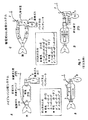
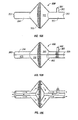
図1A−図1Dを参照すると、図1Aには、従来技術のメイプルソンDシステムの概略図が示されており、ここでは新鮮ガス流(FGF)1は、新鮮ガス送給チューブ2(概略形態のみ示される)を通して遠位取付具3に供給される。このシステムにはバルブは存在しない。システムの作動は、各図における番号付き矢印及び部品番号を参照することによって一層良く理解することができる。吸気の間、肺4へのガスは、新鮮ガス流の入口1及びバッグ7から、流路a、1→2→3→4、及び流路b、7→6→5→4を通して同時に流れる(流路は、図1A及び図1Cの下の一覧表にも示されている)。呼気の間、ガスは、肺4から流路a’、1→2→3→5、及び流路b’、4→5→6→7→8を通して廃棄ガス出口8に流れる。
Operation of Mapleson D System and Circulating CO 2 Absorption System Referring to FIGS. 1A-1D, FIG. 1A shows a schematic diagram of a prior art Mapleson D system, where a fresh gas stream (FGF) is shown. ) 1 is fed to the distal fixture 3 through a fresh gas delivery tube 2 (only schematically shown). There are no valves in this system. The operation of the system can be better understood by referring to the numbered arrows and part numbers in each figure. During inspiration, gas to the lung 4 flows simultaneously from the fresh gas flow inlet 1 and the bag 7 through the flow channels a, 1 → 2 → 3 → 4 and the flow channels b, 7 → 6 → 5 → 4 ( The channels are also shown in the list below FIGS. 1A and 1C). During expiration, gas flows from the lung 4 to the waste gas outlet 8 through the flow path a ′, 1 → 2 → 3 → 5, and the flow path b ′, 4 → 5 → 6 → 7 → 8.
図1Bは、改良型メイプルソンDシステムとして使用されるベインの回路を示す(米国特許第3,856,051号を参照)。このベインの重要な特徴は、新鮮ガス送給チューブ2が回路の近位端部で近位端子に挿入され、このチューブが再呼吸チューブ5を通過して延び、その遠位端部3を回路の遠位端部に有することである。ここで注意すべきは、メイプルソンDシステムは、回路の遠位端部で新鮮ガスを供給するが、但し高流量でこれを行い、かつバルブが使用されないことである。 FIG. 1B shows Bain's circuit used as an improved Mapleson D system (see US Pat. No. 3,856,051). An important feature of this vane is that a fresh gas delivery tube 2 is inserted into the proximal terminal at the proximal end of the circuit, this tube extends through the rebreathing tube 5 and the distal end 3 is connected to the circuit. At the distal end. Note that the Mapleson D system supplies fresh gas at the distal end of the circuit, but does this at high flow rates and no valves are used.
図1Cは、従来の循環式CO2吸収システムを示し、このシステムは、CO2吸収器12、逆止バルブ(すなわち、単一方向性バルブ)4及び9、並びに遠位取付具6で合体する吸気導管5及び呼気導管8を有する。吸気の間、肺7へのガスは、新鮮ガス流源1及びバッグ10から流路c、1→2→3→4→5→6→7、及び流路d、10→12→4→5→6→7を通して同時に流れる。呼気の間、ガスは、肺7から流路c’、1→2→3→12、及び流路d’、7→6→8→9→10→11を通して廃棄ガス出口11に流れる。バルブ4は吸気バルブであり、バルブ9は呼気バルブである。ここで注意すべきは、新鮮ガス流入口3が吸気バルブより近位側にあることである(すなわち、「吸気バルブの手前」に位置する)。 FIG. 1C shows a conventional circulating CO 2 absorption system that combines with a CO 2 absorber 12, check valves (ie, unidirectional valves) 4 and 9, and a distal fixture 6. It has an inspiratory conduit 5 and an expiratory conduit 8. During inhalation, the gas to the lung 7 flows from the fresh gas flow source 1 and the bag 10 to the flow path c, 1 → 2 → 3 → 4 → 5 → 6 → 7, and the flow path d, 10 → 12 → 4 → 5. → 6 → 7 simultaneously. During expiration, gas flows from the lung 7 to the waste gas outlet 11 through the flow path c ′, 1 → 2 → 3 → 12 and the flow path d ′, 7 → 6 → 8 → 9 → 10 → 11. The valve 4 is an inhalation valve, and the valve 9 is an exhalation valve. It should be noted here that the fresh gas inlet 3 is located proximal to the intake valve (that is, “in front of the intake valve”).
従来技術の循環システムにおいては、新鮮ガスは、一方向性吸気バルブの前の(すなわち、その近位側の)CO2吸収器の近く又は吸収器において再循環精製ガスと混合され、吸気導管5内を患者に向けて送られることに注目することが重要である。循環システム内のガスは、従って、迂回経路を一方向に、機械から患者までは吸気導管を経由し、患者から機械までは呼気導管を通って流れ、一部のガスは、次に精製器を通過して吸気導管に至る(また、メイプルソン型回路においては再呼吸チューブが使用されるが、この回路では、高流量の新鮮ガスが呼気ガスを洗い流して二酸化炭素の再呼吸が回避されるので、非再呼吸回路とも呼ばれる)。補助換気システムを循環構成からメイプルソン型非再呼吸構成に修正するためには、多大の努力が必要である。米国特許第4,596,246号は、循環システムと非再呼吸システムの間の変換を容易にする方法及び装置を開示している(ライアルのシステム)。また、ベイン型非再呼吸構成と循環構成の間のより容易な転換を可能にするアダプタ及び取付具が教示されている。しかし、ライアルのシステムにおける構成は両方とも、従来の方式で機能するもので、すなわち、呼気ガスは、ベイン回路と同じように患者に再循環されることはない。 In prior art circulation systems, fresh gas is mixed with recirculated purified gas near or at the CO 2 absorber in front of (ie, proximal to) the one-way intake valve and the intake conduit 5 It is important to note that the inside is sent to the patient. The gas in the circulatory system therefore flows in a bypass path in one direction, from the machine to the patient via the inspiratory conduit and from the patient to the machine through the expiratory conduit, and some gas is then passed through the purifier. Through to the inspiratory conduit (and a rebreathing tube is used in the Mapleson type circuit, where high flow of fresh gas flushes out exhaled gas and avoids carbon dioxide rebreathing. Also called non-rebreathing circuit). A great deal of effort is required to modify the assisted ventilation system from a circulatory configuration to a Mapleson non-rebreathing configuration. U.S. Pat. No. 4,596,246 discloses a method and apparatus that facilitates conversion between a circulatory system and a non-rebreathing system (Rial system). Also taught are adapters and fittings that allow easier conversion between a vane non-rebreathing configuration and a circulating configuration. However, both configurations in the Ryal system function in a conventional manner, i.e., exhaled gas is not recirculated to the patient in the same way as a Bain circuit.
患者を循環システムにおける補助換気システムの吸気ポート及び呼気ポートに接続するための導管及び取付具は、多くの場合に「回路」と呼ばれる。同様に、メイプルソン型システムにおいて使用される新鮮ガスチューブ、呼吸チューブ、ならびに近位側及び遠位側取付具も「回路」と呼ばれる。2つのチューブが基本的に1つの多腔管を形成するように実質的に密接した平行の関係にある時、回路は一本管回路と呼ばれる。例えば、ベイン回路は、新鮮ガスチューブが呼吸チューブの内側にあるので、一本管回路であると考えられる。他の一本管回路は、以下に限定されるものではないが、同軸導管、互いに密接するか又は結合した並列導管、又は共通の壁を共有する導管を含む。 The conduits and fittings for connecting the patient to the inspiratory and expiratory ports of the auxiliary ventilation system in the circulatory system are often referred to as “circuits”. Similarly, fresh gas tubes, breathing tubes, and proximal and distal fittings used in Mapleson type systems are also referred to as “circuits”. A circuit is called a single tube circuit when the two tubes are essentially in a substantially close parallel relationship to form a multilumen tube. For example, a Bain circuit is considered a single circuit because the fresh gas tube is inside the breathing tube. Other single tube circuits include, but are not limited to, coaxial conduits, parallel conduits that are in close proximity or coupled to each other, or conduits that share a common wall.
「Universal F(登録商標)」回路
フクナガに付与された米国特許第4,265,235号を参照すると、異なる種類の呼吸システムに用いる多用途の一本管デバイスが説明されており、これは、従来のシステムを超える多くの利点をもたらす。米国インディアナ州ノーブルビル所在のキング・システムズ・コーポレーションにより「Universal F(登録商標)」として販売されているフクナガのデバイスは、吸気ガスを供給して呼気ガスを除去するのに、場所をとらない同軸設計、すなわちチューブ内チューブの設計になっている。患者に接続する呼吸装置の大きさの縮小などの多くの利点がこの構成から生じる。更に、呼気ガス及び吸気ガスの2つの反対方向の流れが一本管デバイス内で向流になるため、呼気ガスが吸気ガスを暖めてその湿度を保つことになり、このデバイスは、人工鼻として作用する。ベイン回路とは異なり、「Universal F(登録商標)」回路の同軸チューブは、循環システムにおいて使用するのに十分な断面積を有する流路を提供する。
With reference to U.S. Pat. No. 4,265,235 granted to the “Universal F® ” circuit Fukunaga, a versatile single-pipe device for use with different types of respiratory systems is described. It offers many advantages over conventional systems. The Fukunaga device, sold as "Universal F (R)" by King Systems Corporation, Nobleville, Indiana, USA, is a coax that takes no place to supply inspiratory gas and remove exhaled gas The design, that is, the design of the tube in the tube. Many advantages arise from this configuration, such as a reduction in the size of the breathing device connected to the patient. In addition, since the two opposite flows of exhaled gas and inspiratory gas are counter-current in the single tube device, the expiratory gas will warm the inspiratory gas and maintain its humidity, which can be used as an artificial nose. Works. Unlike the Bain circuit, the “Universal F®” circuit coaxial tube provides a flow path with sufficient cross-sectional area for use in a circulation system.
「Universal F2(登録商標)」技術
フクナガ等に付与された米国特許第5,778,872号を参照すると、一本管多腔式回路が開示されており、その実施形態は、米国インディアナ州ノーブルビル所在のキング・システムズ・コーポレーションによって「F2(登録商標)」又は「Universal F2(登録商標)」として販売されている。「F2(登録商標)」の発明は、人工換気システムと補助呼吸法及び麻酔方法を革新的に変えた。「F2(登録商標)」システムは、近位端子からの多腔管(例えば、同軸)システム構成部品の安全かつ容易な取付け及び取外しができる。このことは、呼吸回路の構成部品をより効率的に配並配置し、利用することを可能にしてシステムの性能を向上させ、しかも医療廃棄物及び経費を低減させるものである。一般的に、「Universal F(登録商標)」及び「F2(登録商標)」は、二酸化炭素吸収器を有する循環システム構成に使用されている。「F2(登録商標)」技術に関する詳しい情報は、キング・システムズ・コーポレーションに連絡することにより得ることができる。
Referring to US Pat. No. 5,778,872 to “Universal F2® ” technology Fukunaga et al., A single tube multilumen circuit is disclosed, which embodiment is described in Noble, Indiana, USA. It is sold as “F2®” or “Universal F2®” by King Systems Corporation of the building. The “F2®” invention revolutionized artificial ventilation systems and assisted breathing and anesthesia methods. The “F2®” system allows safe and easy attachment and removal of multilumen (eg, coaxial) system components from the proximal terminal. This allows the components of the breathing circuit to be more efficiently aligned and utilized to improve system performance and reduce medical waste and costs. In general, “Universal F®” and “F2®” are used in circulation system configurations with carbon dioxide absorbers. More information on the “F2®” technology can be obtained by contacting King Systems Corporation.
図1Dは、循環式CO2吸収システムを示しており、これは、「Universal F(登録商標)」回路又は「Universal F2(登録商標)」回路の何れかを使用するものである(後者は、「F2(登録商標)」型近位端子及び分離可能近位取付具を用いることになる)。吸気導管5は、近位端子の遠位において呼気導管8内に同軸に配置される。
呼吸システムと麻酔及び補助換気技術とに関する更なる情報については、米国特許第3,556,097号、第3,856,051号、第4,007,737号、第4,188,946号、第4,265,235号、第4,463,755号、第4,232,667号、第4,596,246号、第5,121,746号、第5,284,160号、第5,778,872号、オーストリア特許第93,941号、英国特許第1,270,946号、Dorsch,J.A.及びDorsch,S.E.著「麻酔装置の会得:構造、管理、及び複雑さ」、ウィリアムズ・アンド・ウィルキンス・カンパニー,ボルチモア(1974)、及び Andrews,J.J.著「吸入麻酔薬投与装置」、Anesthesia,第4版、Miller,Ronald,M.D.編,チャーチル・リビングストン・インコーポレーテッド、ニューヨーク(1986)を参照されたい。これらの参考文献中に引用された文書を含む、ここに引用した全文書の内容(本文)は、以下に完全に再記現されてたものとして、引用によりここに組み入れる。
FIG. 1D shows a recirculating CO 2 absorption system, which uses either a “Universal F®” circuit or a “Universal F2®” circuit (the latter is “F2®” type proximal terminal and separable proximal fitting will be used). The inspiratory conduit 5 is coaxially disposed in the expiratory conduit 8 distal to the proximal terminal.
For further information regarding respiratory systems and anesthesia and assist ventilation techniques, see U.S. Pat. Nos. 3,556,097, 3,856,051, 4,007,737, 4,188,946, 4,265,235, 4,463,755, 4,232,667, 4,596,246, 5,121,746, 5,284,160, 5 778,872, Austrian Patent 93,941, British Patent 1,270,946, Dorsch, J. et al. A. And Dorsch, S .; E. Written by Anesthesia Equipment: Structure, Management, and Complexity, Williams and Wilkins Company, Baltimore (1974), and Andrews, J. et al. J. et al. "An inhalation anesthetic administration device", Anesthesia, 4th edition, Miller, Ronald, M .; D. Ed., Churchill Livingstone, Inc., New York (1986). The contents (text) of all documents cited herein, including those cited in these references, are hereby incorporated by reference as if fully reproduced below.
一層費用効果の高い麻酔及び補助換気システムの必要性
上述の「Universal F(登録商標)」及び「Universal F2(登録商標)」の技術は、医療廃棄物の大幅な低減につながり、更に、患者に対して改良された換気システム及び健康上の利益をもたらした。これらの利点は、出願係属中の米国特許出願出願番号第10/254,700号に記載した「F3(登録商標)」の技術を用いて更に向上することになる。
しかし、患者の看護を更に改善し、一方で呼吸ガスの使用及び/又は無駄を低減することが望まれている。低新鮮ガス流量麻酔技術(「低FGF」又は「低流量」麻酔などとも呼ばれる)は、高流量麻酔法を超える多くの利点を有する。これらは、廃棄される麻酔ガスの量及び医療費を低減させる。更に、このような方法は、良好な加湿を維持し、吸入ガス温度の調節を改良する。低流量法はまた、システムから環境に放出されるガスの量を最小限に抑え、それは手術室の汚染を低減させ、従って、より安全な作業環境が提供される。しかし、低流量技術は、様々な問題があるために、従来の循環システムを用いても、未だに広く普及されていない。
The need for a more cost effective anesthesia and assisted ventilation system The above mentioned “Universal F®” and “Universal F2®” technologies have led to a significant reduction in medical waste and further to patients In contrast to the improved ventilation system and health benefits. These advantages will be further enhanced using the “F3®” technology described in pending US patent application Ser. No. 10 / 254,700.
However, it is desirable to further improve patient care while reducing the use and / or waste of respiratory gases. Low fresh gas flow anesthesia techniques (also called “low FGF” or “low flow” anesthesia, etc.) have many advantages over high flow anesthesia. These reduce the amount of anesthetic gas discarded and medical costs. Furthermore, such a method maintains good humidification and improves the adjustment of the intake gas temperature. The low flow method also minimizes the amount of gas released from the system to the environment, which reduces operating room contamination, thus providing a safer working environment. However, the low flow technology has not yet been widely used even if a conventional circulation system is used due to various problems.
メイプルソンD型システムは、高新鮮ガス流量(高FGF)を必要とするので、低流量には循環システムが最も広く受け入れられているシステムである。麻酔における低流量技術の主要な問題は、患者に供給される麻酔薬の吸気濃度及び肺胞濃度の不確実性及び非予測性である。麻酔薬は、望ましい麻酔の目的(例えば、過剰投薬することなく、外科手術中の患者の意識をなくす)を達成するのに十分な投薬量で投与されるべきである。循環システムの低流量麻酔においては、再生ガスの麻酔薬濃度は、再循環の過程で最初の新鮮ガス濃度(気化器での濃度)から徐々に低下すると考えられる。そのような低下の原因は、呼気ガス及び/又は精製ガスにより希釈されること、漏れ、及び、システム内のプラスチック、ゴム、及び他の材料炭酸ガス吸収剤等との化学反応による分解、吸着及び/又は吸収に起因するものである。高新鮮ガス流量の場合には吸気(麻酔)ガス濃度(FI又はFI)は、送給ガス濃度(FD又はFD=気化器設定濃度)に同等であると仮定することができるが、低流量麻酔では、そのような仮定ができなくなる。 The Mapleson D-type system requires a high fresh gas flow rate (high FGF), so the circulation system is the most widely accepted system for low flow rates. A major problem with low flow techniques in anesthesia is the uncertainty and unpredictability of inspiratory and alveolar concentrations of anesthetics delivered to patients. The anesthetic should be administered at a dosage sufficient to achieve the desired anesthesia objective (eg, without overdose and unconscious patient during surgery). In low flow anesthesia of the circulatory system, the anesthetic concentration of the regenerative gas is thought to gradually decrease from the initial fresh gas concentration (concentration in the vaporizer) during the recirculation process. The cause of such degradation is due to dilution, adsorption and leakage due to dilution with exhaled gas and / or purified gas, leakage, and chemical reaction with plastics, rubber, and other materials carbon dioxide absorbent etc. in the system. This is due to absorption. Intake (anesthetic) gas concentration in the case of high fresh gas flow (FI or F I) is can be assumed to be equivalent to delivery gas concentration (FD or F D = vaporizer setting concentration), low With flow anesthesia, such an assumption cannot be made.
従来技術では、新鮮ガス流量を低下させると、送給ガス濃度(FD)と患者吸気ガス(FI)の間の段階的に増加する勾配(差異)をもたらし、これは、部分的には、システム内の精製ガスによる新鮮ガスの希釈の増大に起因する。例えば、3L/minよりも少ない低FGF中には、吸気ガス濃度と送給ガス濃度(例えば、揮発性麻酔薬気化器の設定濃度)の間に顕著な相異(20%を超える)が起り、これは、患者にとっては麻酔不足となる。 In the prior art, reducing fresh gas flow results in a gradually increasing gradient (difference) between the delivery gas concentration (FD) and the patient inspiratory gas (FI), which is partly the system Due to increased dilution of fresh gas by the refined gas inside. For example, in low FGF less than 3 L / min, there is a significant difference (greater than 20%) between the inspiratory gas concentration and the delivered gas concentration (eg, the volatile anesthetic vaporizer set concentration). This is a lack of anesthesia for the patient.
循環システムを用いる低流量麻酔に伴う更に別の問題は、二酸化炭素吸収器(例えば、ソーダライム)と揮発性麻酔薬との相互作用であり、この化学反応で毒性物質が生成されることが最近報告されている。この問題には、ソーダライムによる揮発性麻酔薬の分解中に一酸化炭素及び「化合物A」が形成されることが含まれる。例えば、循環システムでCOは、ハロタン、エンフルレン、イソフルレン、及びデスフルレンを含む麻酔薬の場合に検出されている。更に、セボフルレンの場合には、セボフルレンは、ソーダライムの存在下で分解し、オレフィン及び腎毒性の可能性を有する「化合物A」になることが知られている。従って、そのような問題を考慮して、麻酔中は常に新鮮ガス流量調節及び気化器設定調節をしながら、吸気及び終末呼気ガス濃度の非常に注意深いモニタリングが行われない限り、低流量麻酔は推奨されない。
低流量麻酔技術によってもたらされる潜在的利益にも関わらず、高流量麻酔方法及びシステムが依然として使用されている。従って、これらのシステム及び方法を改良して、それらを簡単、安全、かつ商業的に実用化する必要性が存在する。
Yet another problem with low flow anesthesia using a circulatory system is the interaction of a carbon dioxide absorber (eg, soda lime) with a volatile anesthetic, which has recently generated toxic substances. It has been reported. This problem includes the formation of carbon monoxide and “Compound A” during the decomposition of volatile anesthetics with soda lime. For example, CO is detected in the circulation system in the case of anesthetics including halothane, enflurane, isoflurane, and desflurane. Furthermore, in the case of sevoflurane, it is known that sevoflurane decomposes in the presence of soda lime to become “Compound A” with potential for olefins and nephrotoxicity. Therefore, low flow anesthesia is recommended unless there is very careful monitoring of inspiratory and end-expiratory gas concentrations while always adjusting fresh gas flow and vaporizer settings during anesthesia in view of such issues. Not.
Despite the potential benefits provided by low flow anesthesia techniques, high flow anesthesia methods and systems are still in use. Therefore, there is a need to improve these systems and methods to make them simple, safe and commercially viable.
本発明は、吸気バルブの後に新鮮ガス流入口を有する新規な呼吸システム及び回路、それらを実施するための構成部品、及びこのようなシステムを用いた人工換気中又は補助換気中及び/又は麻酔中の新鮮ガスの利用を最適化する方法に関する。
好ましい呼吸システムは、本明細書で「F−scrubber」(又は、F−scrubber(登録商標))と呼ぶ新規な精製器モジュールを含み、このモジュールは、吸気バルブと、呼気バルブと、精製器新鮮ガス入口を有する精製器チャンバとを含む精製器ハウジングを有する。第1の実施形態では、「F−scrubber」は、精製器新鮮ガス入口から吸気流路内の吸気バルブより遠位側の点に新鮮ガス流を向けることができるダイバータ機構を含む。第2の実施形態では、「F−scrubber」は、吸気バルブより遠位側の点で吸気経路内に作動関係で接続された吸気バルブ後の新鮮ガス流入口を含む。第3の実施形態では、「F−scrubber」は、ダイバータ及び吸気バルブ後の新鮮ガス流入口の両方を含む。
The present invention relates to a novel breathing system and circuit having a fresh gas inlet after an inhalation valve, components to implement them, and during artificial or auxiliary ventilation and / or during anesthesia using such a system Relates to a method for optimizing the use of fresh gas.
A preferred breathing system includes a novel purifier module referred to herein as “F-scrubber” (or F-scrubber®), which includes an inspiratory valve, an expiratory valve, and a purifier fresher. A purifier housing including a purifier chamber having a gas inlet. In the first embodiment, the “F-scrubber” includes a diverter mechanism that can direct a fresh gas flow from the purifier fresh gas inlet to a point distal to the intake valve in the intake flow path. In the second embodiment, the “F-scrubber” includes a fresh gas inlet after the intake valve operatively connected in the intake path at a point distal to the intake valve. In a third embodiment, “F-scrubber” includes both a diverter and a fresh gas inlet after the intake valve.
また、一方が精製ガスのためのもの(精製ガスポート)、他方が新鮮ガスのためのものである少なくとも2つの入口ポートと(新鮮ガスポート)、呼気ガスを機械に導くためのポート(近位吸気ポート)とを有する新規な「F3(登録商標)」回路が提供される。この回路はまた、患者への呼吸ガスを供給するポート(呼吸ポート)及び患者からの呼気を受取るポート(遠位呼気ポート)を有する呼吸導管も含む。好ましいシステムの実施形態では、上述の精製器モジュールの第1の実施形態に、吸気バルブ後の新鮮ガス流入口を構成する新規な「F3(登録商標)」回路を組み込む。 Also, at least two inlet ports, one for purified gas (purified gas port), the other for fresh gas (fresh gas port), and a port for directing exhaled gas to the machine (proximal) A new “F3®” circuit is provided. The circuit also includes a breathing conduit having a port for supplying breathing gas to the patient (breathing port) and a port for receiving exhaled breath from the patient (distal breathing port). In a preferred system embodiment, the first embodiment of the purifier module described above incorporates a novel “F3®” circuit that constitutes the fresh gas inlet after the intake valve.
一実施形態では、メイプルソンD型システムの改良型とCO2吸収装置付循環システムとの組み合わせで、効率的なガス節約システム(本明細書においては「COMBO」又は「F−COMBO」システムとも呼ぶ)を形成しており、このシステムは、安全かつ予測可能な方式で麻酔薬ガスの利用を最適化することができる。希釈されない新鮮ガスを患者側(すなわち、回路の遠位端部)に供給し、二酸化炭素吸収器を有する精製器回路を通して呼気ガスを循環させることにより、このシステムは、患者がより正確な新鮮ガス濃度(すなわち、麻酔器の流量計による酸素及び笑気の濃度と気化器の濃度設定に近い揮発性麻酔薬濃度)を吸入するようになっている。それに加えて、呼気ガスの再循環は、CO2除去後のガスの再使用を可能にする。その結果、新鮮ガスの利用が最適化される。好ましい実施形態では、COMBOシステムは、一本管多腔式呼吸回路を使用し、導管のうちの少なくとも1つの長さを調節して、再呼吸チューブ内の容積を調節することができる。この実施形態は、再呼吸の量を滴定して予測可能に調節することを可能にし、同じ呼吸導管又は回路を、成人及び小児にも普遍的に利用することができる。再呼吸チューブが患者への再循環ガス(例えば、精製ガス)を供給するようになっていない従来技術のメイプルソン型システムとは対照的に、この新規COMBOにおいては、再呼吸チューブは、患者への再循環ガスを供給するために使用されることになる。 In one embodiment, an improved gas saving system (also referred to herein as a “COMBO” or “F-COMBO” system) is a combination of a modified Mapleson D system and a circulation system with a CO 2 absorber. This system can optimize the use of anesthetic gas in a safe and predictable manner. By supplying undiluted fresh gas to the patient side (ie, the distal end of the circuit) and circulating the exhaled gas through a purifier circuit having a carbon dioxide absorber, the system allows the patient to obtain more accurate fresh gas. Concentrations (i.e. oxygen and laughing gas concentrations with an anesthesia machine flow meter and volatile anesthetic concentration close to the vaporizer concentration setting) are inhaled. In addition, recirculation of exhaled gas allows the gas to be reused after CO 2 removal. As a result, the use of fresh gas is optimized. In a preferred embodiment, the COMBO system can use a single tube multi-lumen breathing circuit and adjust the length of at least one of the conduits to adjust the volume within the rebreathing tube. This embodiment allows the amount of rebreathing to be titrated and adjusted predictably, and the same respiratory conduit or circuit can be universally utilized by adults and children. In this new COMBO, in contrast to prior art Mapleson-type systems where the rebreathing tube is not adapted to supply recirculation gas (eg, purified gas) to the patient, Will be used to supply the recirculated gas.
吸気バルブ後の新鮮ガス流入口を有する新規呼吸システムの別の実施形態は、従来型二重管回路、「Universal F(登録商標)」、「Universal F2(登録商標)」、及び「F3(登録商標)」技術と共に使用することが容易である。これは、呼吸ガス及び/又は麻酔ガスの使用を節約するその性能のために、本明細書では「F−conomy(登録商標)」システムと呼ばれる。代表的な「F−conomy(登録商標)」システムは、患者に及び患者からそれぞれガスを運ぶ対応する導管に精製器モジュールを接続するための吸気及び呼気ポートを含む、循環システムの従来型構成部品の全てを有する。吸気ガスポートと作動関係で接続された一方向性バルブが、補助換気又は麻酔器から患者に向けて精製ガスを流す吸気バルブを形成する。一方向性バルブが、作動関係で呼気ガスポートに接続され、患者からの呼気ガスのみを呼気導管から麻酔器側へ流す呼気バルブを形成する。「F−conomy(登録商標)」システムの実施形態は、上述の新規な「F−scrubber」を組込んでいる。このシステムは、標準的な補助換気及び麻酔器に見られる他の構成部品も含む。 Another embodiment of the novel breathing system with a fresh gas inlet after the inspiratory valve is the conventional double tube circuit, “Universal F®”, “Universal F2®”, and “F3” Trademark) "technology. This is referred to herein as the “F-conomi®” system because of its ability to save on the use of respiratory and / or anesthetic gases. A typical "F-conomi (R)" system is a conventional component of a circulatory system that includes inspiratory and expiratory ports for connecting purifier modules to and to corresponding conduits that carry gas to and from the patient, respectively. Have all. A unidirectional valve operatively connected to the inspiratory gas port forms an inspiratory valve that flows purified gas from the auxiliary ventilation or anesthesia machine toward the patient. A one-way valve is connected to the expiratory gas port in operative relation to form an expiratory valve that allows only expiratory gas from the patient to flow from the expiratory conduit to the anesthesia machine. Embodiments of the “F-conomi®” system incorporate the new “F-scrubber” described above. The system also includes standard auxiliary ventilation and other components found in anesthesia machines.
好ましいシステムの実施形態では、第1又は遠位新鮮ガス流入口ポート(「吸気バルブ後のFGF入口」、「遠位FGF入口」、「第1FGF入口」、又は「低FGF入口」又は同様な用語で呼ばれる)が、吸気バルブより遠位側に設けられる。第2の、すなわち近位新鮮ガス流入口(「近位FGF入口」又は「第2FGF入口」)が精製器モジュールに設けられる(「吸気バルブ前FGF入口」又は「精製器FGF入口」とも呼ばれる)。 In preferred system embodiments, the first or distal fresh gas inlet port ("FGF inlet after intake valve", "distal FGF inlet", "first FGF inlet", or "low FGF inlet" or similar terminology. Is provided distal to the intake valve. A second or proximal fresh gas inlet (“proximal FGF inlet” or “second FGF inlet”) is provided in the purifier module (also referred to as “pre-intake valve FGF inlet” or “purifier FGF inlet”). .
「F−conomy(登録商標)」システムはまた、好ましくは、FGFダイバータバルブを含み、これは、吸気バルブより遠位側の第1新鮮ガス流入口と作動関係で接続され、かつ精製器モジュール上の第2FGF入口と作動関係で接続される(このバルブはまた、「F−diverter(登録商標)」又は「F−converter」などと呼ぶこともできる)。一実施形態では、「F−diverter(登録商標)」は、少なくとも2つの作動位置、すなわち、新鮮ガスが、精製器モジュール上のFGF入口(すなわち、吸気バルブの近位)にのみ供給される第1位置と、新鮮ガス流が吸気バルブより遠位側にある吸気ガス流路内の点にのみ導かれる第2位置とを有する。第2位置において、「F−diverter」は、モニタ麻酔介護(MAC)処置の場合の酸素療法を提供するための鼻カニューレにも容易に接続することができ、「COMBO(登録商標)」システムにも使用することができる。「F−diverter」は、循環システムをベイン又はジャクソン−リーズシステムのようなメイプルソン型システムに容易に変換することができる。「F−diverter(登録商標)」は、酸素療法専用の任意的な特別な入口もまた含むことができる。一実施形態では、「F−diverter」は、精製器FGF入口を任意的に密封し、FGFを吸気バルブより遠位側の吸気流路内の位置にのみ向けることができる。 The “F-conomi®” system also preferably includes an FGF diverter valve that is operatively connected to a first fresh gas inlet distal to the intake valve and on the purifier module. (The valve may also be referred to as "F-diver (R)" or "F-converter", etc.). In one embodiment, the “F-diver®” is the first where at least two operating positions, ie, fresh gas is supplied only to the FGF inlet on the purifier module (ie, proximal to the intake valve). 1 position and a second position where the fresh gas flow is directed only to a point in the intake gas flow path distal to the intake valve. In the second position, the “F-diverter” can also be easily connected to a nasal cannula to provide oxygen therapy in the case of a monitor anesthesia care (MAC) procedure, with the “COMBO®” system. Can also be used. "F-diverter" can easily convert a circulation system to a Mapleson type system such as a Bain or Jackson-Leeds system. “F-diverter®” can also include an optional special entrance dedicated to oxygen therapy. In one embodiment, the “F-diverter” can optionally seal the purifier FGF inlet and direct the FGF only to a location in the intake flow path distal to the intake valve.
「F−conomy(登録商標)」システム及び「COMBO(登録商標)」システムは、補助換気法及び麻酔方法に新規なシステム及び方法を提供する。低FGFでの麻酔又は補助換気を供給する簡単で安全な方法が、本発明によって可能にされる。一実施形態では、高新鮮ガス流量(高FGF)では、新鮮ガス流が精製器モジュール内に向ける位置にダイバータバルブを位置し、低新鮮ガス流量(低FGF)では、直接患者へ供給するために、新鮮ガス流を吸気バルブより遠位側の点に向ける位置にダイバータを切換えることによって達成することができる。ダイバータは、少なくとも2つのFGF出口を有し、従って、ダイバータ出口に接続された新鮮ガス流ラインを切り離さずに、FGF流を吸気バルブより近位側と遠位側とに切換えることができる。患者は、人間又は人間以外とすることもできる。 The “F-conomi®” and “COMBO®” systems provide new systems and methods for assisted ventilation and anesthesia methods. A simple and safe method of supplying anesthesia or assisted ventilation with low FGF is enabled by the present invention. In one embodiment, high fresh gas flow (high FGF) places the diverter valve in a position where the fresh gas flow is directed into the purifier module, and low fresh gas flow (low FGF) to deliver directly to the patient. This can be accomplished by switching the diverter to a position that directs the fresh gas flow to a point distal to the intake valve. The diverter has at least two FGF outlets, and thus can switch FGF flow proximally and distally from the intake valve without disconnecting the fresh gas flow line connected to the diverter outlet. The patient can be human or non-human.
既存の精製器モジュール及び呼吸システムは、本発明の新規なダイバータバルブの組込むことにより、また吸気バルブより遠位側にFGF入口のための新鮮ガス流アダプタを設けることにより修正することができる。ダイバータバルブ及びアダプタは、キットとして一緒に提供することができる。
一実施形態では、新規なFGFアダプタ(又は「アダプタ」)は、第1直径(すなわち、最小の断面積)のFGF導管又はニップルを有する硬いハウジングを有し、この導管又はニップルは、第2直径の吸気経路導管内に流体接続状態で終端となる。第1直径は、従来からFGFを供給する配管に使用されているものが好ましい。一般的に、小さい第1直径は、このような配管の使用を新鮮ガス送給チューブとしてのみの役目に限定する。第2直径は、第1直径よりもはるかに大きく、吸気経路導管は、FGFチューブとしての役目に限定されない。従って、吸気導管又は再呼吸導管は、FGF導管と混同されてはならない。例えば、循環システムにおいては、患者は、直接吸気導管から新鮮ガス及び精製ガスを吸入する。
Existing purifier modules and breathing systems can be modified by incorporating the novel diverter valve of the present invention and by providing a fresh gas flow adapter for the FGF inlet distal to the intake valve. The diverter valve and adapter can be provided together as a kit.
In one embodiment, the novel FGF adapter (or “adapter”) has a rigid housing having a first diameter (ie, minimum cross-sectional area) FGF conduit or nipple, which conduit or nipple has a second diameter. Ends with fluid connection in the intake path conduit. The first diameter is preferably that conventionally used for piping for supplying FGF. In general, the small first diameter limits the use of such piping to serve only as a fresh gas delivery tube. The second diameter is much larger than the first diameter, and the intake passage conduit is not limited to serve as an FGF tube. Thus, inspiratory or rebreathing conduits should not be confused with FGF conduits. For example, in a circulatory system, the patient inhales fresh and purified gas directly from the inspiratory conduit.
一実施形態では、新鮮ガス流アダプタは、「Universal F2(登録商標)」近位端子の遠位側端部の吸気ポートに接続可能である。別の実施形態では、上述の新規アダプタの特徴は、(1)麻酔器又は近位呼気ポート、(2)精製ガス吸気ポート、(3)新鮮ガス流入口ポート(FGFポート)、(4)患者又は遠位吸気ガスポート、及び(5)患者又は遠位呼気ガスポート、を有する新規な多腔管近位端子内に組み込まれる。これらの新規な近位端子は、「F3(登録商標)」近位端子と呼ぶことができる。 In one embodiment, the fresh gas flow adapter is connectable to the inspiratory port at the distal end of the “Universal F2®” proximal terminal. In another embodiment, the features of the new adapter described above are: (1) anesthesia or proximal exhalation port, (2) purified gas inspiratory port, (3) fresh gas inlet port (FGF port), (4) patient Or in a new multilumen proximal terminal having a distal inspiratory gas port and (5) a patient or distal expiratory gas port. These new proximal terminals can be referred to as “F3®” proximal terminals.
別の実施形態では、上述の新規アダプタの特徴は、多腔管の「Universal F2(登録商標)」用近位端子のように、一本管回路に対する多腔管近位端子への作動関係で接続のための新規な多腔管近位取付具の中に組み込まれる。新規な多腔管近位取付具は、吸気バルブより遠位側の吸気ガス流路内への新鮮ガス流入口を提供する。これらの新規な近位取付具は、本明細書では「F3(登録商標)」近位取付具と呼ぶ場合がある。 In another embodiment, the features of the new adapter described above are in operative relationship to a multilumen proximal terminal relative to a single tube circuit, such as the “Universal F2®” proximal terminal of a multilumen tube. Incorporated into a novel multilumen proximal fitting for connection. The new multilumen proximal fitting provides a fresh gas inlet into the intake gas flow path distal to the intake valve. These novel proximal fittings may be referred to herein as “F3®” proximal fittings.
本発明の新規なFGFアダプタ、近位端子、及び近位取付具はまた、吸気及び/又は呼気導管(又は、場合によっては再呼吸導管)内にフィルタ手段を含むように修正することができ、この場合には、フィルタを収容して望ましい流量を維持するために、フィルタ手段を収容する導管の部分に適切な寸法調節がなされる。
吸気バルブより後の位置に新鮮ガス流入口を形成することができ、使用場所においてユーザーが補助換気機械に対して迅速に着脱することができる新規な一体型回路もまた開示される。
The novel FGF adapter, proximal terminal, and proximal fitting of the present invention can also be modified to include filter means in the inspiratory and / or expiratory conduit (or possibly rebreathing conduit) In this case, appropriate dimensional adjustments are made to the portion of the conduit that contains the filter means to contain the filter and maintain the desired flow rate.
Also disclosed is a novel integrated circuit that can form a fresh gas inlet at a location after the intake valve and that can be quickly attached to and removed from the auxiliary ventilation machine by the user at the point of use.
本発明は、図面、及び、上述の要約を詳述し、付加的な特徴を提示する以下の更なる説明を参照することにより、より良く理解することができる。本発明の理解を容易にするために、以下の図においては、一部の取付け構成部品は示されず、及び/又は、一部の取付けは、簡略化した形で示されている。例えば、構成部品を互いに間隔をもって支持する支柱又はフランジは示されていず、壁の厚み及び相対的なチューブの直径及び長さは、一定の縮尺ではない場合がある。 The invention can be better understood with reference to the drawings and the following further description that sets forth the above summary and presents additional features. In order to facilitate understanding of the present invention, some mounting components are not shown and / or some mountings are shown in simplified form in the following figures. For example, struts or flanges that support the components spaced apart from each other are not shown, and the wall thickness and relative tube diameter and length may not be to scale.
定義
従来技術及び本発明の更なる説明を容易にするために、いくつかの用語が以下で定義され、かつ、本明細書の他の場所で定義される。本明細書で用いられる場合、用語「人工又は補助換気」はまた、麻酔中を含む緊急又は長期の両方の状況における「制御された及び自然な換気」を包含するものとする。麻酔、人工換気、又は補助換気で用いるシステムは、補助換気システムと呼ぶこともできる。新鮮ガスは、以下に限定されるものではないが、酸素のようなガス、笑気、ハロタン、エンフルレン、イソルフレン、デスフルレン、及びセボフルレンのような麻酔薬を含み、一般的に流量計及び気化器を用いて供給される。FGFは、新鮮ガス流を意味する。
Definitions In order to facilitate the further description of the prior art and the present invention, a number of terms are defined below and defined elsewhere in this specification. As used herein, the term “artificial or auxiliary ventilation” is also intended to encompass “controlled and natural ventilation” in both emergency and long-term situations, including during anesthesia. A system used for anesthesia, artificial ventilation, or auxiliary ventilation can also be referred to as an auxiliary ventilation system. Fresh gases include, but are not limited to, gases such as oxygen, laughing gas, halothane, enflurane, isoflurane, desflurane, and sevoflurane, and generally include flow meters and vaporizers. Supplied. FGF means fresh gas flow.
患者側に向いた導管の端部は、遠位端部と呼ばれ、吸気ガス源に面するか又は接続した導管の端部は、近位端部と呼ぶものとする。同様に、呼吸回路の遠位端部において、例えば、患者気道デバイス(すなわち、気管内チューブ、喉頭マスク、喉頭チューブ、フェースマスクなど)に接続されるか又はこれらに向けられた取付具及び端子又は他のデバイスは、遠位取付具及び遠位端子と呼ばれ、呼吸回路の近位にある取付具及び端子又は他のデバイスは、近位取付具及び近位端子と呼ばれることになる。従って、遠位アダプタ又は遠位コネクタは、回路の遠位又は患者端部に位置すると考えられる。 The end of the conduit facing the patient will be referred to as the distal end, and the end of the conduit facing or connected to the inspiratory gas source shall be referred to as the proximal end. Similarly, at the distal end of the breathing circuit, for example, fittings and terminals connected to or directed to a patient airway device (ie, endotracheal tube, laryngeal mask, laryngeal tube, face mask, etc.) or Other devices will be referred to as distal fittings and distal terminals, and fittings and terminals or other devices proximal to the breathing circuit will be referred to as proximal fittings and proximal terminals. Thus, the distal adapter or connector is considered to be located distal to the circuit or at the patient end.
多腔式一本管呼吸回路関連における近位端子は、回路の機械側端部に位置するもので、少なくとも2つの独立流路を分離させ、平行に密接又は並んだ関係にあるか又は同軸状回路であるチューブによって形成された少なくとも1つの流路が吸気ガス源に接続することができ、同時に別の流路が吸気ガスポートから離れた排出ポートに接続することができるようになっている。近位端子はまた、2つの独立流路を共通流路に合体させる剛性ハウジング、例えばY字形取付具、好ましくは隔壁を有するY字形取付具を含むことができる。例えば、近位端子は、端子内の第1流路を麻酔器の呼気ポートと作動関係で接続することができ、端子内の独立した第2流路を吸気ポートと作動関係で接続でき、第1流路及び第2流路は、近位端子の遠位端部で患者へのガス及び患者からのガスを搬送するための分れた可撓性チューブに独立して接続することができる。可撓性チューブは、並置型配列、一方が他方内にある配列、僅かに間隔をもった配列、又は同軸配列により、一本の多腔管を形成する構成とすることができる。本発明の近位端子は、補助換気機械からの新鮮ガス流を受取り、この新鮮ガス流を端子ハウジング内の独立流路のうちの1つに合体させるためのポートを更に含み、「F3(登録商標)」近位端子と呼ばれる。 A proximal terminal in the context of a multi-lumen single-pipe breathing circuit is located at the machine end of the circuit and separates at least two independent channels and is in close or parallel relationship in parallel or coaxial. At least one flow path formed by a tube as a circuit can be connected to an intake gas source, and at the same time, another flow path can be connected to an exhaust port remote from the intake gas port. The proximal terminal can also include a rigid housing that combines two independent channels into a common channel, such as a Y-shaped fixture, preferably a Y-shaped fixture with a septum. For example, the proximal terminal can connect the first flow path in the terminal in operative relation with the exhalation port of the anesthesia machine, and can connect the independent second flow path in the terminal in operative relation with the inspiratory port The first flow path and the second flow path can be independently connected to a separate flexible tube for carrying gas to and from the patient at the distal end of the proximal terminal. The flexible tubes can be configured to form a single multi-lumen tube with a side-by-side arrangement, one arrangement within the other, a slightly spaced arrangement, or a coaxial arrangement. The proximal terminal of the present invention further includes a port for receiving a fresh gas flow from the auxiliary ventilation machine and coalescing the fresh gas flow into one of the independent flow paths in the terminal housing. Trademark) "called the proximal terminal.
多腔式一本管回路の近位端子に近位取付具を使用することは、「Universal F2(登録商標)」発明によってもたらされた新規な概念であり、これは、補助換気機械の近位端子に複数の導管チューブを、対応する多腔管近位取付具によって、容易に着脱できるようにした初めてのものである。本発明のいくつかの実施形態で導管のチューブは、近位端子に直接に結合することもあるが(これは、「Universal F2(登録商標)」発明以前においては、従来技術の近位端子を用いて行われ、従って、「F2(登録商標)」前の近位端子及び他の回路構成部品を単一デバイスとして全て廃棄又は殺菌することを必要とした)。本発明の他の実施形態では、導管チューブは、近位端子の対応するポートに係合できる近位取付具に接続することができる。近位取付具は、フィルタ手段を含むことができるか、又はフィルタに係合することができ、これが、次に近位端子に接続される。好ましい実施形態では、流路のうちの1つに新鮮ガス流入口を有し、「F3(登録商標)」近位取付具と呼ばれる新規な多腔管近位取付具が開示される。 The use of a proximal fitting at the proximal terminal of a multi-lumen single-pipe circuit is a novel concept brought about by the “Universal F2®” invention, which is close to the auxiliary ventilation machine. This is the first time that a plurality of conduit tubes can be easily attached to and detached from the terminal terminal by a corresponding multi-lumen tube proximal fitting. In some embodiments of the present invention, the tube of the conduit may be coupled directly to the proximal terminal (this was prior to the “Universal F2®” invention, the prior art proximal terminal Therefore, it was necessary to discard or sterilize all the proximal terminals and other circuit components before “F2®” as a single device). In other embodiments of the present invention, the conduit tube can be connected to a proximal fitting that can engage a corresponding port of the proximal terminal. The proximal fitting can include filter means or can engage the filter, which is then connected to the proximal terminal. In a preferred embodiment, a novel multilumen proximal fitting is disclosed that has a fresh gas inlet in one of the channels and is referred to as an “F3®” proximal fitting.
近位FGFアダプタ又は「F3(登録商標)」近位アダプタは、吸気バルブ後のFGF入口により低流量を安全に行うことができるという、本明細書に開示された驚くべき発見によって可能になった新規な概念であり、従来、FGF入口を吸気バルブより遠位側に設けることの必要性は気付かれていなかった。「F3(登録商標)」近位アダプタは、COMBO回路の近位吸気管に又は循環システムの、吸気バルブより遠位側の任意の位置に容易に着脱することができる。 Proximal FGF adapters or “F3®” proximal adapters have been made possible by the surprising discovery disclosed herein that low flow can be safely performed by the FGF inlet after the intake valve. This is a new concept, and conventionally, the necessity of providing the FGF inlet on the distal side of the intake valve has not been realized. The “F3®” proximal adapter can be easily attached and removed to the proximal intake tube of the COMBO circuit or to any location distal to the intake valve of the circulation system.
本明細書において、低新鮮ガス流量(「低FGF」又は「低流量」)は、約3リットル/分(L/min)よりも少ない流量であり、高新鮮ガス流量(「高FGF」又は「高流量」)は、約3L/minを超える流量である。吸気導管(吸気チューブ、管腔、又はパイプとも呼ばれる)は、循環システムにおいて患者が吸入する導管である。再呼吸導管は、メイプルソン型システムにおけるように患者が吸入及び呼出する導管であり、新鮮ガスは、新鮮ガス送給用すなわち供給用チューブから再呼吸導管に送給される。 As used herein, a low fresh gas flow rate (“low FGF” or “low flow rate”) is a flow rate that is less than about 3 liters per minute (L / min) and a high fresh gas flow rate (“high FGF” or “ "High flow rate") is a flow rate that exceeds about 3 L / min. An inspiratory conduit (also referred to as an inspiratory tube, lumen, or pipe) is a conduit that a patient inhales in the circulatory system. A rebreathing conduit is a conduit that is inhaled and called by a patient, as in a Mapleson-type system, and fresh gas is delivered from the fresh gas delivery or supply tube to the rebreathing conduit.
ガス節約システム
「F3(登録商標)」COMBOシステム
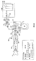
図2を参照すると、本発明の新規な呼吸回路の一実施形態を利用する本発明の補助換気システムが図2Aに概略の形態で示されている。
垂直破線20の右は、ダイバータ30以外は従来型の循環システムである。破線20の左は、メイプルソンD型回路である。従って、この「COMBO(登録商標)」システムは、これらの従来技術の回路の特徴を組み合わせている。このシステムはまた、これらに限定するものではないが、F−COMBO、F−Combo、又はCOMBO、又はF3システムと呼ぶこともできる。
Gas saving system
“F3®” COMBO System Referring to FIG. 2, an auxiliary ventilation system of the present invention utilizing one embodiment of the novel breathing circuit of the present invention is shown in schematic form in FIG. 2A.
To the right of the vertical broken line 20 is a conventional circulation system other than the diverter 30. The left side of the broken line 20 is a Mapleson D-type circuit. Thus, the “COMBO®” system combines the features of these prior art circuits. This system can also be referred to as, but not limited to, an F-COMBO, F-Combo, or COMBO, or F3 system.
供給源1(例えば、麻酔器)からの新鮮ガス流は、流路ダイバータ30を経て、新鮮ガス送給チューブ2(部分的な概略形態で示される)を通過する。流れダイバータ30は、精製器回路内に精製器新鮮ガス入口ポート15を有するように循環回路を変更するために設けられる。FGF入口15は、一般的に、CO2吸収器の近くか又はその位置にある。ダイバータは、CO2吸収器12の上部にある新鮮ガス入口ポート15を閉鎖し、そのために、新鮮ガスを呼吸導管の遠位端部3に直接供給することができる。換言すれば、FGFは、精製器モジュールをバイパスし、そのためにFGFは精製ガスと混合されることはない。この実施形態では、FGFチューブ2は、ベインと同様に、近位端子50に堅く結合されたFGF導管56を含み、かつ新鮮ガス流内腔58も含む。新鮮ガス流は、共通の吸気/呼気導管5の遠位端部上の取付具3に連続的に供給することができる(導管5は、再呼吸チューブ、共通呼吸導管などとも呼ばれる)。(一実施形態では、FGFポート15が閉鎖されるか又は存在しない時は、ダイバータは必要ないと考えられる。) The fresh gas flow from source 1 (eg, anesthesia machine) passes through fresh gas delivery tube 2 (shown in partial schematic form) via flow path diverter 30. A flow diverter 30 is provided to modify the circulation circuit to have a purifier fresh gas inlet port 15 in the purifier circuit. The FGF inlet 15 is generally near or at the location of the CO 2 absorber. The diverter closes the fresh gas inlet port 15 at the top of the CO 2 absorber 12 so that fresh gas can be supplied directly to the distal end 3 of the breathing conduit. In other words, the FGF bypasses the purifier module so that the FGF is not mixed with the purified gas. In this embodiment, the FGF tube 2 includes an FGF conduit 56 that is rigidly coupled to the proximal terminal 50, as well as a vane, and also includes a fresh gas flow lumen 58. A fresh gas stream can be continuously supplied to the fixture 3 on the distal end of the common inspiratory / expiratory conduit 5 (conduit 5 is also referred to as a rebreathing tube, a common respiratory conduit, etc.). (In one embodiment, when the FGF port 15 is closed or absent, a diverter may not be needed.)
共通呼吸チューブ5内の呼気ガスは、呼気ポート22において再循環モジュールに入り、一方、再循環モジュールからの精製ガスは、吸気ポート24において再呼吸チューブ5に供給される。第1の一方向性バルブ26は呼気バルブとして作用し、呼気ガスが呼気ポート22から再循環モジュールに入るが、逆には流れないようにする。第2の一方向性バルブ28は吸気バルブとして作用し、再循環モジュールからの精製、新鮮、及び/又は再生ガスが吸気ポート24に流れるが、逆には流れないようにする。 Exhaled gas in the common breathing tube 5 enters the recirculation module at the exhalation port 22, while purified gas from the recirculation module is supplied to the rebreathing tube 5 at the inspiratory port 24. The first one-way valve 26 acts as an exhalation valve, preventing exhaled gas from entering the recirculation module from the exhalation port 22 but not conversely. The second one-way valve 28 acts as an intake valve, allowing purified, fresh, and / or regenerative gas from the recirculation module to flow to the intake port 24 but not vice versa.
図2A−図2Cを参照すると、ベインとは異なり、チューブの容積及びその内容物の濃度が変えられるように、再呼吸導管5の寸法を変更することができ、このようにして、吸気ガスを各患者について調節することができ、かつ、精製ガスの再呼吸を制御することができる(これは、ライアルシステムとは対照的である)。例えば、チューブ5は、「ULTRA−FLEX(登録商標)」チューブとすることができる。例えば、チューブ5の長さを軸線方向に調節することによるチューブ5の寸法の調節により、制御を行うことができる。従って、モニタリング装置によって提供される吸気ガス及び/又は呼気終期ガス濃度データに応じて、チューブの容量及び内容物の増減を行うことができる。この特徴は、COMBOを用いる低流量麻酔を容易にする。 Referring to FIGS. 2A-2C, unlike Bain, the size of the rebreathing conduit 5 can be changed so that the volume of the tube and the concentration of its contents can be changed, thus allowing the inspiratory gas to flow. It can be adjusted for each patient and the rebreathing of purified gas can be controlled (this is in contrast to the trial system). For example, the tube 5 can be a “ULTRA-FLEX®” tube. For example, the control can be performed by adjusting the dimensions of the tube 5 by adjusting the length of the tube 5 in the axial direction. Therefore, the capacity and contents of the tube can be increased or decreased according to the inspiratory gas and / or end expiratory gas concentration data provided by the monitoring device. This feature facilitates low flow anesthesia with COMBO.
ここで注意すべきは、本発明の新規COMBOシステムにおいては、従来型の循環システムとは異なり、麻酔器から直接送給される新鮮ガスは、機械/精製器回路内で(すなわち、吸気バルブの近位で)混合又は希釈されることがない。新鮮ガス流が患者の近くに送給されるので、吸気麻酔薬濃度(FI)は送給濃度(FD)にほぼ等しい。従って、麻酔医は流量計及び気化器に示された麻酔ガス濃度を吸入ガスとして信頼することができる。メイプルソンDシステムとは対照的に、新規なこのシステムにおいては、呼気ガスは、全てが廃棄されるのではなく、その一部は「再生ガス」として再使用され、並びに回路内のガス容積及び圧力を一様にするように精製器モジュールを再循環する(ライアルシステムとは異なり)。この新規な「Fシステム」は、呼吸及び麻酔換気の制御及びその特性における驚くべき改良をもたらし、一方で麻酔ガスの浪費を回避するものである。 It should be noted here that in the novel COMBO system of the present invention, unlike conventional circulation systems, fresh gas delivered directly from the anesthesia machine is fed into the machine / purifier circuit (ie, the intake valve). (Proximal) is not mixed or diluted. Since a fresh gas stream is delivered close to the patient, the inspiratory anesthetic concentration (F I ) is approximately equal to the delivery concentration (F D ). Accordingly, the anesthesiologist can rely on the anesthetic gas concentration indicated on the flow meter and vaporizer as the inhalation gas. In this new system, in contrast to the Mapleson D system, exhaled gas is not all discarded, but a portion of it is reused as “regenerative gas” and the gas volume and Recycle the purifier module to make the pressure uniform (unlike the liaison system). This new “F system” provides a surprising improvement in the control and characteristics of breathing and anesthesia ventilation, while avoiding wasting anesthetic gas.
好ましくは、使用中の再呼吸チューブ5の容積は、1回換気量(VT)よりも大きい値に調節され、「精製ガス」との新鮮ガスの混合が最小化される。これは、新鮮ガス(麻酔薬)の最適利用、並びにO2及びCO2再呼吸制御を可能にする。
好ましい実施形態では、再呼吸チューブの長さは、複数の使用法に対して可変とすることができる。手術室、ICU、救急処置室、呼吸看護病棟、成人及び小児患者などにおいて、同じ呼吸システムを普遍的に使用することができる。
Preferably, the volume of the rebreathing tube 5 in use is adjusted to a value greater than the tidal volume (V T ) to minimize mixing of fresh gas with “purified gas”. This allows for optimal utilization of fresh gas (anesthetic) and O 2 and CO 2 rebreathing control.
In preferred embodiments, the length of the rebreathing tube can be variable for multiple uses. The same respiratory system can be universally used in operating rooms, ICUs, emergency rooms, respiratory nursing wards, adult and pediatric patients, and the like.
図2Bは、新規な近位端子50を概略の形態で示しており、端子50は単独で取り外すことができ、また呼吸導管5に、及び新鮮ガスチューブ2と新鮮ガス流内腔58に接続することができる。内腔58及び導管5は、多腔管近位取付具(図示せず)によって端子50に接続される。近位端子50は、FGF導管56は、呼吸チューブとしてではなく、FGF送給導管として役立つのに十分であるだけの小さい直径を有し、かつ、それが同様な断面積のチューブに接続される点で、FGF送給チューブとしてのみ機能するようになった、独特のものである。例えば、この端子は、呼吸システムの吸気ポート及び呼気ポートの独立した内腔に接続するのではなく、これは、それらのポートが循環システムに関連して形成されたものである。精製ガス及び呼気ガスは、FGF入口52で受取られるFGF導管56内で新鮮ガスと混合することなく、共通呼吸内腔54を通過することができる。 FIG. 2B shows the novel proximal terminal 50 in schematic form, which can be removed alone and connected to the respiratory conduit 5 and to the fresh gas tube 2 and the fresh gas flow lumen 58. be able to. The lumen 58 and the conduit 5 are connected to the terminal 50 by a multi-lumen proximal fitting (not shown). Proximal terminal 50 has a diameter that is small enough to allow FGF conduit 56 to serve as an FGF delivery conduit rather than as a breathing tube, and it is connected to a tube of similar cross-sectional area. In that respect, it is unique because it only functions as an FGF delivery tube. For example, this terminal does not connect to the independent lumens of the inspiratory and expiratory ports of the respiratory system, but those ports are formed in connection with the circulatory system. Purified gas and exhaled gas can pass through the common respiratory lumen 54 without mixing with fresh gas in the FGF conduit 56 received at the FGF inlet 52.
また、付加的な流路分割端子6が概略の形態で示されており、これは、従来の方式で第1の方向に流れを結合し、第2の方向に流れを分離するために使用される。端子6は、「F2(登録商標)」型近位端子又はY字形アダプタとすることができる。呼気ガスは呼気ポート22に導かれ、吸気用「精製ガス」は、吸気ポート24から受取れられる。FGF導管56内の新鮮ガスは、導管56がFGF内腔58と作動関係で接続された時に内腔58に導かれる。簡単に着脱することができる構成部品の組合せは、個々の滅菌又は廃棄を容易にする。 An additional channel split terminal 6 is also shown in schematic form, which is used to combine the flow in the first direction and separate the flow in the second direction in a conventional manner. The Terminal 6 may be an “F2®” type proximal terminal or a Y-shaped adapter. Exhaled gas is directed to the exhalation port 22 and inhaled “purified gas” is received from the inspiratory port 24. Fresh gas in the FGF conduit 56 is directed to the lumen 58 when the conduit 56 is operatively connected to the FGF lumen 58. The combination of components that can be easily attached and removed facilitates individual sterilization or disposal.
この実施形態及び本明細書に開示される他の発明に関して、取付具の近位端部及び遠位端部、端子、その他の構成部品は、対応する構成部品に適合するような寸法及び独特な形状とすることができ、ユーザーは、適合する構成部品を接続するのみである。これは、在庫管理を容易にし、接合される適合構成部品間のより良好な装着をもたらす。
いくつかの場合では、本明細書に開示されるこの呼吸回路その他のものの複数の構成部品(例えば、チューブ及び取付具)が永久的に接合され、構成部品を分離させるためには、構成部品の破壊を潜在的にもたらすような相当な力が必要である。他の実施形態では、呼吸回路の複数の構成部品を一体に形成することができる。本発明のアダプタ、取付具、及び端子は、剛性の単一ハウジングを含み、このハウジングは、内腔の形状及びその構成を剛に保持し、一方、それに接続されたチューブ類は、アダプタ、取付具、及び端子よりも薄い壁を有し、一般的に可撓性である。本発明の構成部品を作るための好ましい材料は、以下に限定されるものではないが、「Universal F(登録商標)」及び「Universal F2(登録商標)」の構成部品に使用されている材料及び/又はそれに適する材料を含む。当業者に公知の標準的なチューブ寸法及びスリップコネクタを使用することができる(例えば、ISOによって定められた規格)。
With respect to this embodiment and other inventions disclosed herein, the proximal and distal ends of the fixture, terminals, and other components are sized and unique to fit the corresponding components. It can be shaped and the user simply connects the matching components. This facilitates inventory management and results in better fit between mating fitted components.
In some cases, multiple components (e.g., tubes and fittings) of this breathing circuit and others disclosed herein may be permanently joined and separated in order to separate the components. There must be considerable power that can potentially cause destruction. In other embodiments, multiple components of the breathing circuit can be integrally formed. The adapters, fittings, and terminals of the present invention include a rigid single housing that rigidly retains the shape of the lumen and its configuration, while the tubing connected thereto is an adapter, attachment. It has a thinner wall than the tool and the terminal and is generally flexible. Preferred materials for making the components of the present invention include, but are not limited to, the materials used for the components of “Universal F®” and “Universal F2®” and And / or suitable materials. Standard tube dimensions and slip connectors known to those skilled in the art can be used (eg, standards set by ISO).
再び図2Aを参照すると、システムの構成部品はまた、好ましくは、リザーババッグ又は換気デバイス10、スカベンジャに取付け可能な廃棄ガス出口11、CO2吸収器12、逆止バルブ26及び28(吸気バルブ28及び呼気バルブ26)、吸気導管5’、呼気導管8’、及び近位アダプタ50に接続した近位端子6を含む。近位アダプタ(又はアダプタ)50は、本明細書では、新鮮ガス流アダプタとも呼ばれ、FGF入口52とFGF導管56の反対端のFGF出口53とを有する。共通(再呼吸)導管54は、図2Aに示されているシステムにおける精製ガス及び呼気ガスの両方を搬送する。 Referring again to FIG. 2A, the components of the system also preferably include a reservoir bag or ventilation device 10, a waste gas outlet 11 that can be attached to a scavenger, a CO 2 absorber 12, check valves 26 and 28 (intake valves 28). And the expiratory valve 26), the inspiratory conduit 5 ′, the expiratory conduit 8 ′, and the proximal terminal 6 connected to the proximal adapter 50. The proximal adapter (or adapter) 50, also referred to herein as a fresh gas flow adapter, has an FGF inlet 52 and an FGF outlet 53 at the opposite end of the FGF conduit 56. A common (rebreathing) conduit 54 carries both purified gas and exhaled gas in the system shown in FIG. 2A.
システムの作動は、番号付き矢印及び/又は各部の番号の参照によって更に良好に理解される。ガス流の一覧は、図2Aに示されている。例えば、好ましい実施形態では、吸気の間、肺4へのガスは、新鮮ガス流供給源1及びバッグ/ベンチレータ10から吸気経路a、1→2→3→4、及び吸気経路b、10→12→28→5’→6→5→3→4を通して同時に流れる。呼気の間、ガスは、肺4から廃棄ガス出口11に呼気経路a’、1→2→3→5、及び呼気経路b’、4→3→5→6→8’→26→10→11を通して流れる。 The operation of the system is better understood by reference to numbered arrows and / or part numbers. A list of gas flows is shown in FIG. 2A. For example, in a preferred embodiment, during inspiration, gas to the lungs 4 from the fresh gas flow source 1 and the bag / ventilator 10 is inspiratory path a, 1 → 2 → 3 → 4, and inspiratory path b, 10 → 12. → 28 → 5 ′ → 6 → 5 → 3 → 4 During exhalation, gas flows from the lung 4 to the waste gas outlet 11 to the exhalation path a ′, 1 → 2 → 3 → 5, and exhalation path b ′, 4 → 3 → 5 → 6 → 8 ′ → 26 → 10 → 11. Flowing through.
ダイバータ30は、好ましくは、COMBOシステム内に含まれ、好ましくは、ユーザーが新鮮ガス流を精製器12上の新鮮ガス流入口15に導き、又はFGF入口52に向けることを可能にするバルブを内部に有する。これは、「F−diverter」のレバーを手で動かして行われ、又は、補助換気又は麻酔器制御装置及びプロセッサと作動関係で接続された適切な電気機械式バルブ機構によって行うことができる。一実施形態では、「F−diverter」バルブは、三方向ストップコックが嵌合された筒状バルブハウジングを含み、入口導管及び出口導管は、バルブハウジングに接続され、ストップコックの回転によってストップコック内の内腔と通じることができる。 The diverter 30 is preferably included within the COMBO system, preferably with an internal valve that allows the user to direct the fresh gas stream to the fresh gas inlet 15 on the purifier 12 or to the FGF inlet 52. Have. This can be done by manually moving the "F-diverter" lever or by a suitable electromechanical valve mechanism connected in operative relationship with the auxiliary ventilation or anesthesia controller and processor. In one embodiment, the “F-diverter” valve includes a cylindrical valve housing fitted with a three-way stopcock, and the inlet and outlet conduits are connected to the valve housing, and the stopcock rotates to enter the stopcock. Can communicate with the lumen of
図2Cを参照すると、別の形態のCOMBO回路が部分概略断面の形態で示されている。単腔導管14が、共通呼吸チューブとして役立つ。フィルタを含むフィルタハウジング16は、図のように一体化して取付けるか、又は標準的な方式で導管14の近位端部に接続される。導管14の近位端部は、図2A及び図2Bの流路分割端子6に接続可能であり、一方、FGFチューブ2は、同様にダイバータ30に接続される。導管14の遠位端部18は、FGF導管62を含む患者取付具60に接続可能である。再呼吸導管14の長さは、内部容積を調整するために調節することができる。導管14は、「ULTRA−FLEX(登録商標)」チューブ又は他の適切な可変長のチューブで形成することができる。取付具60、バルブ30、及び/又は導管14のような構成部品は、個々に又はキット形式で提供することができる。 Referring to FIG. 2C, another form of COMBO circuit is shown in partial schematic cross-sectional form. A single lumen conduit 14 serves as a common breathing tube. The filter housing 16 containing the filter is mounted integrally as shown or connected to the proximal end of the conduit 14 in a standard manner. The proximal end of the conduit 14 can be connected to the flow dividing terminal 6 of FIGS. 2A and 2B, while the FGF tube 2 is connected to the diverter 30 as well. The distal end 18 of the conduit 14 is connectable to a patient fitting 60 that includes an FGF conduit 62. The length of the rebreathing conduit 14 can be adjusted to adjust the internal volume. The conduit 14 may be formed of an “ULTRA-FLEX®” tube or other suitable variable length tube. Components such as fixture 60, valve 30, and / or conduit 14 may be provided individually or in kit form.
すなわち、一実施形態では、再循環モジュール、モジュールへの呼気ガスを供給し、モジュールからのガスを受取るために該モジュールに対してその近位端部開口部において作動関係で接続された再呼吸チューブ、及び新鮮ガスのための遠位入口を備える新規な換気及び麻酔システムが提供される。遠位入口は、再呼吸チューブより遠位側部分に配置され、又は再呼吸チューブの遠位端部と作動関係で接続された遠位取付具内に配置される。新鮮ガス流入口は、図2A及び図2Bに示すように再呼吸導管の近位端部に配置され、適切なチューブを通して再呼吸導管を通ってその遠位端部に向けることができ、又は、FGF入口は、回路の遠位端部に位置することができる。
再循環モジュールは、精製回路を含むことが好ましく、この回路は、少なくとも2つの一方向性バルブ、呼気入口導管、CO2精製器、排気ベント、精製ガス出口導管、スクイーズバッグ及び/又はベンチレータを含むことができる。
That is, in one embodiment, a recirculation module, a rebreathing tube connected in operative relationship to the module at its proximal end opening to supply exhalation gas to the module and receive gas from the module And a novel ventilation and anesthesia system with a distal inlet for fresh gas is provided. The distal inlet is located in a portion distal to the rebreathing tube or in a distal fitting connected in operative relationship with the distal end of the rebreathing tube. The fresh gas inlet can be located at the proximal end of the rebreathing conduit as shown in FIGS. 2A and 2B and can be directed through its appropriate tube through the rebreathing conduit to its distal end, or The FGF inlet can be located at the distal end of the circuit.
The recirculation module preferably includes a purification circuit, which includes at least two one-way valves, an exhalation inlet conduit, a CO 2 purifier, an exhaust vent, a purified gas outlet conduit, a squeeze bag and / or a ventilator. be able to.
「F−conomy(登録商標)」システム
従来技術の循環システムにおいては、新鮮ガスは、吸気バルブより近位側で精製器モジュール内に向けられている(すなわち、「吸気バルブ前の新鮮ガス流入口」である)。吸気バルブ後の新鮮ガス流ラインへは、新鮮ガスの過剰な損失をもたらすと考えられていた。従って、低流量時に、吸気バルブ後のFGF流入口が、送給濃度に近似の麻酔ガスの吸気濃度をもたらすという発見は意外であった。本発明は、顕著なガス節約及び他の利点(例えば、新鮮ガスと精製器内のソーダライムとの相互作用によって悪影響を受ける呼吸ガスの危険も低減させる)を有する。本発明において、新鮮ガスは、呼気相の間を含め、吸気導管内に連続的に導入され、吸気導管は、新鮮ガスのためのリザーバとして作用する。リザーバ内の新鮮ガス及び再循環モジュールからの精製ガスは、吸気相の間に吸入され、呼気ガスの一部分は、図3−図6に概略で示すように再循環され、精製されて、再使用される。
“F-conomi®” System In prior art circulation systems, fresh gas is directed into the purifier module proximal to the intake valve (ie, “fresh gas inlet before intake valve” "). It was thought that the fresh gas flow line after the intake valve would result in excessive fresh gas loss. Thus, it was surprising to find that at low flow rates, the FGF inlet after the intake valve provides an anesthetic gas intake concentration that approximates the delivery concentration. The present invention has significant gas savings and other advantages, such as reducing the risk of breathing gas that is adversely affected by the interaction of fresh gas with soda lime in the purifier. In the present invention, fresh gas is continuously introduced into the inspiratory conduit, including during the expiration phase, and the inspiratory conduit acts as a reservoir for the fresh gas. Fresh gas in the reservoir and purified gas from the recirculation module are inhaled during the inspiratory phase, and a portion of the exhaled gas is recirculated, purified and reused as shown schematically in FIGS. Is done.
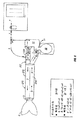
図3A−図3Cと図9A及び図9Fとを参照すると、本発明によって構成された「F−conomy(登録商標)」システムの構成部品及び作動が説明されている。図1及び/又は図2に示されているデバイスに使用されるものと類似又は同じ部分は、図3A−図3C内で同様に番号付けされる。ガス流矢印は、理解を容易にするために、この図において前の図のように番号付けされている。麻酔器は、新鮮ガス供給源100を有し、これは、当業者に公知の適切な読取装置及び制御装置を有する酸素及び亜酸化窒素のようなガスを供給するための流量計102及び104を含む。気化器106は、流量計からの出口を有するラインに接続され、そのために、揮発性麻酔薬を新鮮ガス出口108に送ることができる。 Referring to FIGS. 3A-3C and FIGS. 9A and 9F, the components and operation of an “F-conomi®” system constructed in accordance with the present invention will be described. Parts similar or identical to those used in the device shown in FIGS. 1 and / or 2 are similarly numbered in FIGS. 3A-3C. The gas flow arrows are numbered in this figure as in the previous figure for ease of understanding. The anesthesia machine has a fresh gas source 100 which includes flow meters 102 and 104 for supplying gases such as oxygen and nitrous oxide with appropriate readers and controls known to those skilled in the art. Including. The vaporizer 106 is connected to a line having an outlet from the flow meter so that a volatile anesthetic can be sent to the fresh gas outlet 108.
制御レバー112を有するダイバータバルブ110が、新鮮ガス供給ライン114を有するライン内に配置される。ダイバータバルブは、ダイバータバルブ入口導管118と出口導管120及び122との接合部にあるバルブハウジングの対応シートに装着された、筒状の回転可能ストッパ内の2つの交差導管116を含む。レバー112は、ハウジング内のストッパを回転させることができる。レバー112が出口導管122に合わされたときには、新鮮ガスは、出口導管122に流れることができず、新鮮ガスは、出口導管120に流れることができる。レバー112が出口導管120に合わされたときには、新鮮ガスは、出口導管120ではなく、出口導管122に流れることができる。レバー112が各出口導管の間にある時には、バルブ内の各導管の幅に応じて、新鮮ガスは、両方の出口導管に同時に流れることができる。レバー112が入口導管118に整列した時には、ダイバータバルブを通過する流れは阻止されるが、これが望ましくない場合には、バルブが完全に閉止される位置に回転するのを防止するために、レバーストップを取付けることができる。 A diverter valve 110 having a control lever 112 is arranged in a line having a fresh gas supply line 114. The diverter valve includes two intersecting conduits 116 in a cylindrical rotatable stopper mounted on the corresponding seat of the valve housing at the junction of diverter valve inlet conduit 118 and outlet conduits 120 and 122. The lever 112 can rotate a stopper in the housing. When the lever 112 is mated to the outlet conduit 122, fresh gas cannot flow to the outlet conduit 122 and fresh gas can flow to the outlet conduit 120. When the lever 112 is mated to the outlet conduit 120, fresh gas can flow to the outlet conduit 122 rather than the outlet conduit 120. When the lever 112 is between each outlet conduit, depending on the width of each conduit in the valve, fresh gas can flow to both outlet conduits simultaneously. When the lever 112 is aligned with the inlet conduit 118, flow through the diverter valve is blocked, but if this is not desired, a lever stop can be used to prevent the valve from rotating to a fully closed position. Can be installed.
代替的な実施形態では、本発明のFGFダイバータは、FGFを入口導管内に受取り、それを複数の出口導管に向けるマニホルドを含むことができる。出口導管の各々は、別々の流量制御装置を有することができる。例えば、2つの出口導管は、全開又は半開とすることができ、精製器FGF入口と吸気バルブ後のFGF入口とに同時に流れる新鮮ガスのレベルの変更を可能にする。流量制御装置は、手動で操作でき、又は補助換気システムのプロセッサ及び制御装置への適切な組込みを用いて電気機械的に操作することができる。 In an alternative embodiment, the FGF diverter of the present invention can include a manifold that receives FGF in an inlet conduit and directs it to multiple outlet conduits. Each outlet conduit can have a separate flow control device. For example, the two outlet conduits can be fully open or half open, allowing a change in the level of fresh gas flowing simultaneously to the purifier FGF inlet and the FGF inlet after the intake valve. The flow control device can be operated manually or it can be operated electromechanically using appropriate integration into the processor and controller of the auxiliary ventilation system.
新鮮ガスが導管122から流出することができる時には、新鮮ガスは、精製器12の新鮮ガス入口ポート15に流入することになり、一方、新鮮ガスが導管120から流出することができる時には、新鮮ガスは、呼吸回路160内の新鮮ガス流アダプタ130に導くことができる。呼吸回路160の近位端子の分解部分概略図が、図3Bに示されている。吸気ポート24から来る精製ガスは、アダプタ130の近位ポート132内に導かれ、遠位ポート138から流出する。新鮮ガス源100からの新鮮ガスは、アダプタ130の吸気経路導管に向けて、新鮮ガス入口136を通して新鮮ガス流導管134内に導かれる。例示的な近位アダプタ130が、図9A及び図9Fに別々に示されている。 When fresh gas can flow out of the conduit 122, fresh gas will flow into the fresh gas inlet port 15 of the purifier 12, while when fresh gas can flow out of the conduit 120 Can be directed to the fresh gas flow adapter 130 in the breathing circuit 160. An exploded partial schematic view of the proximal terminal of the breathing circuit 160 is shown in FIG. 3B. Purified gas coming from the intake port 24 is directed into the proximal port 132 of the adapter 130 and exits the distal port 138. Fresh gas from the fresh gas source 100 is directed into the fresh gas flow conduit 134 through the fresh gas inlet 136 toward the intake path conduit of the adapter 130. An exemplary proximal adapter 130 is shown separately in FIGS. 9A and 9F.
構成部品150は、吸気及び呼気導管の同軸構成を有する「Universal F2(登録商標)」近位端子であることが分かる。米国特許5,778,872号に説明した「F2(登録商標)」の発明は、取付具内の各チューブが同軸、並置関係又は平行で僅かに間隔をもった関係、又は共通壁を共有する関係か否かに係わりなく、容易に接続されて呼吸回路を形成することができる多腔管近位端子及び多腔管取付具の使用を開拓したものである。近位取付具は、ユーザーにより使用場所で容易に近位端子から取外すことができる。 It can be seen that component 150 is a “Universal F2®” proximal terminal with a coaxial configuration of inspiratory and expiratory conduits. The “F2®” invention described in US Pat. No. 5,778,872 is that the tubes in the fixture share a common wall, coaxial, side-by-side relationship or parallel, slightly spaced relationship It pioneers the use of a multilumen tube proximal terminal and multilumen tube fitting that can be easily connected to form a breathing circuit, regardless of the relationship. The proximal fitting can be easily removed from the proximal terminal at the point of use by the user.
図示の例示的システムにおいて、近位端子は、アダプタ130の遠位ポート138への作動関係で接続のための吸気ポート152と、再循環モジュール内の呼気ポートへの作動関係で接続のための呼気ポート154とを含む。呼気ポート152は、アダプタ130から流れるガスがポート156への内側チューブ内のみを流れることの理解を容易にするために、テーパーの付いた円錐形内部で示されているが、ポート152は、アダプタ130のポート138と嵌合する適切な形状及び寸法にすることもできる。 In the exemplary system shown, the proximal terminal is an inhalation port 152 for connection in connection to the distal port 138 of the adapter 130 and an exhalation for connection in connection to the exhalation port in the recirculation module. Port 154. The exhalation port 152 is shown inside a tapered cone to facilitate understanding that the gas flowing from the adapter 130 flows only in the inner tube to the port 156, but the port 152 is Appropriate shapes and dimensions to fit 130 ports 138 may also be used.
遠位ポートすなわち患者側ポート156及び158は、内側導管162及び外側導管164を有する可撓性一本管呼吸導管160に接続可能である。好ましい実施形態では、導管162及び164は、それらの近位端部において、本発明の説明を容易にするため示されていない近位取付具に接続され、この近位取付具は、次に、ユーザーにより使用場所で近位端子に容易に取付け及び取外しすることができる。ここで注意すべきことを特徴とするとは、吸気チューブ162が、アダプタ130及び近位端子150の吸気導管を通して吸気ポート24と流体接続状態にあることである(すなわち、新鮮ガス及び精製ガスは、吸気導管162内に流れる)。これは、精製器からポート24に達するガスが、外側チューブ5にのみ流れることができ、チューブ5は、吸気の間は吸気チューブとして、呼気の間は呼気チューブとして、両方に機能する(これを反対方向の流れの矢印で示す)図2A及び図2Bのシステムとは対照的である。図3A及び図3Bは、循環システムとして機能し、吸気チューブ162内の流れは患者に向かい、一方、外側流路5(例えば、チューブ162の遠位端部に対して近位側の吸気チューブ164内)の流れは、患者から遠ざかる方向である。 The distal or patient side ports 156 and 158 are connectable to a flexible single-pipe respiratory conduit 160 having an inner conduit 162 and an outer conduit 164. In a preferred embodiment, conduits 162 and 164 are connected at their proximal ends to a proximal fixture not shown to facilitate the description of the invention, which proximal fixture is then: It can be easily installed and removed from the proximal terminal at the point of use by the user. It should be noted that the intake tube 162 is in fluid communication with the intake port 24 through the intake conduit of the adapter 130 and proximal terminal 150 (ie, fresh gas and purified gas are Flows into the intake conduit 162). This means that gas reaching the port 24 from the purifier can only flow into the outer tube 5, which acts both as an inspiratory tube during inspiration and as an exhalation tube during exhalation (this is In contrast to the system of FIGS. 2A and 2B (indicated by the opposite flow arrows). 3A and 3B function as a circulatory system, where the flow in the inspiratory tube 162 is directed toward the patient, while the inspiratory tube 164 proximal to the outer flow path 5 (eg, the distal end of the tube 162). The inner flow is away from the patient.
図3Cは、ガス源100と作動関係で取付けられた「F−scrubber」の好ましい実施形態を示す。一実施形態では、アダプタ130及びダイバータ110は、概略で示すように、精製器モジュールを改修するためのキットとして提供することができる。別の例示的な実施形態では、「F−scrubber」は、精製器モジュール及びダイバータバルブ110を含む(アダプタ130又はガス源100に接続可能であるが、これらを持たない)。別の例示的な実施形態では、「F−scrubber」は、精製器モジュール及びアダプタ130(ダイバータバルブ110又はガス源100を備えていないが、これらに接続可能である)を含む。 FIG. 3C shows a preferred embodiment of an “F-scrubber” attached in operative relationship with the gas source 100. In one embodiment, the adapter 130 and diverter 110 can be provided as a kit for retrofitting the purifier module, as shown schematically. In another exemplary embodiment, the “F-scrubber” includes a purifier module and a diverter valve 110 (which can be connected to the adapter 130 or the gas source 100 but does not have them). In another exemplary embodiment, the “F-scrubber” includes a purifier module and an adapter 130 (which does not include the diverter valve 110 or the gas source 100, but can be connected thereto).
図3A及び図3Bのシステムは、既存の補助換気システムをダイバータバルブを使用して修正することにより、及び、任意の回路、例えば近位端部に「F2(登録商標)」近位端子を有する回路の近位端部にアダプタ130を接続することにより、容易に形成することができる。従って、「F2(登録商標)」の発明によってもたらされた補助換気システム及び構成部品における顕著な驚くべき改良は、吸気バルブ後の新鮮ガス流入口を用いて更に高められる。これは、一実施形態において、非限定的な例が図3Bに示されている本発明の新規な近位アダプタの追加により助長される。 The system of FIGS. 3A and 3B modifies an existing auxiliary ventilation system using a diverter valve and has an optional circuit, eg, a “F2®” proximal terminal at the proximal end. It can be easily formed by connecting an adapter 130 to the proximal end of the circuit. Thus, the remarkable and surprising improvement in the auxiliary ventilation system and components brought about by the “F2®” invention is further enhanced by using a fresh gas inlet after the intake valve. This is facilitated in one embodiment by the addition of the novel proximal adapter of the present invention, a non-limiting example shown in FIG. 3B.
図9Fを参照すると、吸気ポート24には、例えば図5のシステム構成におけるアダプタ130の近位端子132内のネジ部に対応するネジ部が設けられ、永久的又は半永久的な相互取り付けがもたらされる。適合する構成部品への接続のみが可能とされるように、様々な接続及び閉塞手段を本発明の構成部品に利用することができる。例えば、嵌合ネジ部を有する構成部品との接続のために、遠位ポート138にネジ部を形成することもできる。 Referring to FIG. 9F, the intake port 24 is provided with a threaded portion corresponding to, for example, a threaded portion in the proximal terminal 132 of the adapter 130 in the system configuration of FIG. 5 to provide a permanent or semi-permanent interconnection. . Various connection and closure means can be utilized for the components of the present invention so that only connections to compatible components are possible. For example, the distal port 138 can be threaded for connection to a component having a mating thread.
図4を参照すると、本発明により構成された「F−conomy(登録商標)」システムの別の実施形態が示されている。この実施形態では、新鮮ガス流入口がF2近位端子150より遠位側に設けられる。ガス流矢印は、この図においては、判り易くするために前の図のように番号付けされる。図9Dに個別に示されている新規な多腔管近位取付具170は、近位端子150の患者ポート156及び158と作動関係で接続される。内側内腔176は、ポート156に接続され、一方、外側内腔178は、ポート158に接続される。取付具170及び端子150は、米国特許第5,778,872号に開示されるような剛性の材料で形成することができ、この材料は、患者からのガスを搬送する可撓性配管を形成する材料よりも全体的に厚く、より剛性である。内腔176及び178は、剛性の一体化FGF導管180によって間隔をもった関係に保たれる同軸パイプとして形成される。FGF導管180は、FGF入口182を有し、その反対側の端部において内側導管176に接続される。FDF導管180は、FGF入口に適する直径を一般的に有することになるだけであるが、内側導管176は、吸気導管の一部として役立つための十分な断面積を有するのが好ましい。しかし、一実施形態において、システムの流れのパターンが逆である場合には、FGF導管180は、外側導管178に接続することができる(導管178は、吸気導管として機能するのに適切な断面積を有するであろう)。本発明の多腔管近位取付具(F3近位取付具)は、F2多腔管近位端子を用いるシステムにおける吸気バルブより遠位側においての新鮮ガス流の迅速な接続を可能にする。
多腔式フィルタ190は、取付具170の遠位端部に接続された状態で示されている。フィルタハウジングの内側及び外側内腔は、可撓性呼吸導管192及び194に一体化することができ、或いは取り外し可能とすることができる。図10Cでは、新鮮ガス流入口にフィルタ190の機能を組み合わせているが、その作動及び構成は、他の点では実質的に同様である。
Referring to FIG. 4, another embodiment of the “F-conomi®” system constructed in accordance with the present invention is shown. In this embodiment, a fresh gas inlet is provided distal to the F2 proximal terminal 150. The gas flow arrows are numbered in this figure as in the previous figure for clarity. The novel multilumen proximal fitting 170, shown separately in FIG. 9D, is operatively connected to patient ports 156 and 158 of the proximal terminal 150. Inner lumen 176 is connected to port 156, while outer lumen 178 is connected to port 158. The fixture 170 and terminal 150 can be formed of a rigid material as disclosed in US Pat. No. 5,778,872, which forms a flexible tubing that carries gas from the patient. It is generally thicker and more rigid than the material it does. Lumens 176 and 178 are formed as coaxial pipes that are kept in a spaced relationship by a rigid integral FGF conduit 180. The FGF conduit 180 has an FGF inlet 182 and is connected to the inner conduit 176 at its opposite end. While the FDF conduit 180 will generally only have a diameter suitable for the FGF inlet, the inner conduit 176 preferably has sufficient cross-sectional area to serve as part of the intake conduit. However, in one embodiment, if the system flow pattern is reversed, the FGF conduit 180 can be connected to the outer conduit 178 (conduit 178 is suitable cross-sectional area to function as an intake conduit). Would have). The multilumen tube proximal fitting (F3 proximal fitting) of the present invention allows for a quick connection of fresh gas flow distal to the intake valve in a system using F2 multilumen proximal terminals.
Multi-lumen filter 190 is shown connected to the distal end of fixture 170. The inner and outer lumens of the filter housing can be integrated into the flexible breathing conduits 192 and 194 or can be removable. In FIG. 10C, the fresh gas inlet is combined with the function of the filter 190, but the operation and configuration are otherwise substantially the same.
図5は、本発明により構成された一本管ではなく、二双管の「F−conomy(登録商標)」システムを示す。従来の二本管循環システムに、ダイバータバルブ110及び近位アダプタ130を組込むように改修されている。このシステムは、新鮮ガス流入口を、精製器12から吸気バルブ後の入口に迅速に切り換えることを可能にし、逆もまた同じである。
図6のシステムは、図5のシステムと実質的に同じ方式で作動する。このシステムは、多腔管近位端子201が別々の流れを一本管多腔式導管210内に合流させることのみが異なる。図6の端子201が、図9Cの端子200のFGF導管224を含まないことを除いては、端子201は、図9Cに示されている端子200と実質的に同じである。導管210は、吸気内腔212及び呼気内腔214を有する。内腔212及び214は、近位端子201の遠位端部、例えば、図9Cのポート220及び222に直接接合することができ、又は、それらに、複数の平行導管の多腔管端子への同時接続をもたらすF2近位取付具によって接続することができる。
FIG. 5 shows a “F-conomi®” system with two twin tubes rather than a single tube constructed in accordance with the present invention. The conventional double pipe circulation system has been modified to incorporate the diverter valve 110 and the proximal adapter 130. This system allows a fresh gas inlet to be quickly switched from the purifier 12 to the inlet after the intake valve, and vice versa.
The system of FIG. 6 operates in substantially the same manner as the system of FIG. This system differs only in that the multilumen proximal terminal 201 merges separate flows into the single tube multilumen conduit 210. Terminal 201 is substantially the same as terminal 200 shown in FIG. 9C, except that terminal 201 of FIG. 6 does not include FGF conduit 224 of terminal 200 of FIG. 9C. Conduit 210 has an inspiratory lumen 212 and an expiratory lumen 214. Lumens 212 and 214 can be joined directly to the distal end of proximal terminal 201, eg, ports 220 and 222 of FIG. 9C, or they can be connected to a multilumen tube terminal of multiple parallel conduits. Can be connected by an F2 proximal fitting that provides simultaneous connection.
図7は、本発明の「F3(登録商標)」近位端子250の例示的な実施形態を断面図で示す。端子は、それが、新鮮ガス流入口をもうけることによって吸気バルブ後の新鮮ガス流アダプタとしても機能することができることを除いては、同軸「Universal F2(登録商標)」近位端子と実質的に同じ構成である。端子は、補助換気機械への永久的又は半永久的な取付けに対しては、好ましくは金属で作製され、又は、定期的な処分の可能性が高い場合には、剛性の医用等級のプラスチックで製作される。 FIG. 7 illustrates in cross-section an exemplary embodiment of the “F3®” proximal terminal 250 of the present invention. The terminal is substantially the same as the coaxial “Universal F2®” proximal terminal, except that it can also function as a fresh gas flow adapter after the intake valve by providing a fresh gas inlet. It is the same configuration. Terminals are preferably made of metal for permanent or semi-permanent attachment to auxiliary ventilation machines, or of rigid medical grade plastic if periodic disposal is likely Is done.
端子250は、機械側呼気ポート252、精製ガス吸気ポート254、新鮮ガス流入口ポート(FGFポート)256、患者吸気ガスポート258、及び患者呼気ガスポート260を含む。F2近位端子と同様に、吸気ポート254は、吸気バルブより遠位側において機械側吸気ポートに作動関係で接続することができ、呼気ポート252は機械呼気ポートと作動関係で接続することができる。同軸F2近位取付具及び回路構成部品は、ポート258及び260に接続することができる。FGFポート256において供給される新鮮ガスは、近位吸気内腔262に入り、遠位吸気内腔264に流れ、ポート258から出る。呼気ガスは、ポート260から呼気内腔266内に流れ、呼気ポート252から出る。ここでは同軸の実施形態が示されているが、図9C及び図9E(以下で説明する)に示されている実施形態は、F3近位端子が様々な構成を有することができることを示している。
一実施形態では、内腔264及び/又は内腔266は、フィルタを内部に有するライン内フィルタチャンバを含むことができる。フィルタ手段は、実質的に図10B又は図10Cに示すように形成することができる。
Terminal 250 includes machine side exhalation port 252, purified gas inhalation port 254, fresh gas inlet port (FGF port) 256, patient inspiratory gas port 258, and patient exhaled gas port 260. Similar to the F2 proximal terminal, the inspiratory port 254 can be operatively connected to the mechanical inspiratory port distal to the inspiratory valve, and the expiratory port 252 can be operatively connected to the mechanical expiratory port. . Coaxial F2 proximal fittings and circuit components can be connected to ports 258 and 260. Fresh gas supplied at the FGF port 256 enters the proximal inspiration lumen 262, flows to the distal inspiration lumen 264, and exits the port 258. Expiratory gas flows from port 260 into expiratory lumen 266 and exits expiratory port 252. Although a coaxial embodiment is shown here, the embodiment shown in FIGS. 9C and 9E (described below) shows that the F3 proximal terminal can have various configurations. .
In one embodiment, lumen 264 and / or lumen 266 can include an in-line filter chamber having a filter therein. The filter means can be formed substantially as shown in FIG. 10B or 10C.
図8は、本発明の「F3(登録商標)」近位取付具を断面図で示す。新鮮ガス流入口を設けることによって取付具が吸気バルブ後の新鮮ガス流アダプタとしても役立つことを除いては、この取付具は、同軸「Universal F2(登録商標)」近位取付具と実質的に同じ構成である。取付具275は、機械側呼気ポート280、精製ガス吸気ポート282、新鮮ガス流入口ポート(FGFポート)284、患者吸気ガスポート286、及び患者呼気ガスポート288を含む。F2近位取付具と同様に、吸気ポート282は、対応する「Universal F2」近位端子を通して吸気バルブより遠位側において機械側吸気ポートと作動関係で接続することができ、同様に、呼気ポート280は、機械側呼気ポートと作動関係で接続することができる。 FIG. 8 illustrates in cross-section the “F3®” proximal fitting of the present invention. This fixture is substantially similar to the coaxial “Universal F2®” proximal fitting, except that the fitting also serves as a fresh gas flow adapter after the intake valve by providing a fresh gas inlet. It is the same configuration. The fixture 275 includes a machine side exhalation port 280, a purified gas inhalation port 282, a fresh gas inlet port (FGF port) 284, a patient inhalation gas port 286, and a patient exhalation gas port 288. Similar to the F2 proximal fitting, the inspiratory port 282 can be operatively connected to the mechanical inspiratory port distally from the inspiratory valve through a corresponding “Universal F2” proximal terminal, as well as the expiratory port. 280 can be operatively connected to a machine side exhalation port.
FGF入口ポート284からのFGFの流れは、内側内腔290内で精製ガスと混合し、内腔290は、図示の実施形態では、多腔管患者呼吸導管294の内側可撓性導管292と作動関係で接続される。内側導管は、外側可撓性導管296内に収容され、この外側可撓性導管は、取付具275からの内側導管内の吸気ガス及び外側導管内の呼気ガスの同軸の流れを維持する。一実施形態では、取付具275には、それに永久的に結合された導管292及び296が設けられる。別の実施形態では、それらの導管は、多腔式フィルタと、次にその取付具とに接続することができる。ここでは同軸の実施形態が示されているが、図9B及び図9D(以下で更に説明する)に示されている実施形態は、F3近位取付具が様々な構成を有することができることを示している。 The flow of FGF from the FGF inlet port 284 mixes with purified gas within the inner lumen 290, which in the illustrated embodiment operates with the inner flexible conduit 292 of the multilumen patient breathing conduit 294. Connected in a relationship. The inner conduit is housed in an outer flexible conduit 296 that maintains a coaxial flow of inspiratory gas in the inner conduit from the fitting 275 and exhaled gas in the outer conduit. In one embodiment, fixture 275 is provided with conduits 292 and 296 permanently coupled thereto. In another embodiment, the conduits can be connected to a multi-lumen filter and then to its fitting. Although a coaxial embodiment is shown here, the embodiment shown in FIGS. 9B and 9D (discussed further below) shows that the F3 proximal fitting can have a variety of configurations. ing.
図9Bは、別の形態のF3近位取付具300を示す。取付具300は、機械呼気ポート302、精製ガス吸気ガスポート304、新鮮ガス流入口ポート(FGFポート)306、患者吸気ガスポート308、及び患者呼気ガスポート310を含む。F2近位取付具と同様に、吸気ポート304は、対応する「Universal F2」近位端子を通して吸気バルブより遠位側において機械側吸気ポートと作動関係で接続することができ、同様に、呼気ポート302は、機械側呼気ポートと作動関係で接続することができる。 FIG. 9B shows another form of F3 proximal fitting 300. The fixture 300 includes a mechanical exhalation port 302, a purified gas inspiratory gas port 304, a fresh gas inlet port (FGF port) 306, a patient inspiratory gas port 308, and a patient exhaled gas port 310. Similar to the F2 proximal fitting, the inspiratory port 304 can be operatively connected to the mechanical inspiratory port distally from the inspiratory valve through a corresponding “Universal F2” proximal terminal, as well as the expiratory port. 302 can be operatively connected to a machine side exhalation port.
吸気内腔を形成する第1チューブ312は、呼気内腔を形成する第2チューブと平行に並んで間隔をもった関係にある。適切な寸法調節(及び、取付具が流体密封接合を形成する必要がある場合には、チューブ312及び314の反対端の間に間隙を形成する)を行うことにより、ポート302及び304は、対応するF2近位端子と作動関係で接続することができる。例えば、図9CのF3近位端子は、仮にそれがFGFポート224を持たない場合には、F2近位端子を形成し、その場合には、ポート302及び304は、ポート220及び222にそれぞれ接続することができる。 The first tube 312 that forms the inhalation lumen is in parallel with and spaced from the second tube that forms the exhalation lumen. By making the appropriate dimensional adjustments (and creating a gap between the opposite ends of tubes 312 and 314 if the fixture needs to form a fluid-tight joint), ports 302 and 304 can be Can be connected in operative relationship with the F2 proximal terminal. For example, the F3 proximal terminal of FIG. 9C forms an F2 proximal terminal if it does not have an FGF port 224, in which case ports 302 and 304 connect to ports 220 and 222, respectively. can do.
図9Eは、図7のF3近位端子の代替的実施形態を示す。吸気ポート256が遠位吸気内腔264と合体するために移動されていることを除けば、それらの端子は実質的に同一であり、従って、同じ部品番号が付されている。この実施形態では、環状壁部320、及び新鮮ガス導管と外側内腔との接合部322は、内側及び外側内腔の間隔の空いた関係を強化する。環状壁部320は、それに接続された取付具からガスが内側チューブ264及びポート254に向けてのみ流れることの理解を容易にするために、テーパー状の円錐形内部を備えるものとして示されているが、実際には、ポート254は、対応する取付具と嵌合するような適切な形状及び寸法にされる。 FIG. 9E shows an alternative embodiment of the F3 proximal terminal of FIG. Except that the inspiratory port 256 has been moved to merge with the distal inspiratory lumen 264, their terminals are substantially identical and are therefore given the same part number. In this embodiment, the annular wall 320 and the fresh gas conduit and outer lumen junction 322 enhance the spaced relationship between the inner and outer lumens. The annular wall 320 is shown as having a tapered conical interior to facilitate understanding that gas flows only from the fittings connected thereto towards the inner tube 264 and the port 254. In practice, however, the ports 254 are appropriately shaped and dimensioned to mate with corresponding fittings.
以上から明らかなように、吸気バルブ後のFGF入口を構成するために、様々な構成部品を形成することができる。それらの構成部品は、フィルタを含むように更に修正することができる。代替的に、単一回路又はその実質的な部分は、吸気バルブ後のFGF入口と組み合わせた多くの異なる特徴を組み込むように形成することができる。例えば、図10Aは、新鮮ガス流入口が組込まれた本発明の単腔フィルタを断面で示している。従って、フィルタ350は、本発明に従う近位(又は遠位)FGFアダプタとして使用することができる。 As is apparent from the above, various components can be formed to configure the FGF inlet after the intake valve. Those components can be further modified to include a filter. Alternatively, a single circuit or a substantial portion thereof can be formed to incorporate many different features in combination with the FGF inlet after the intake valve. For example, FIG. 10A shows in cross-section a single lumen filter of the present invention incorporating a fresh gas inlet. Thus, the filter 350 can be used as a proximal (or distal) FGF adapter according to the present invention.
ハウジング350は、近位内腔352、遠位内腔354、及びフィルタコンパートメント356を含み、これらは、全て、近位ポート358及び遠位ポート360と流体接続状態にある。FGF入口導管362は、FGF入口364及び好ましくは内腔352への接続部を有する。当業者は理解するであろうが、望ましい濾過及び流量を達成するのに適切な品質及び表面積のフィルタ366が設けられる(例えば、フィルタの寸法及び特性は、米国インディアナ州ノーブルビル所在のキング・システムズ・コーポレーションによって提供される単腔濾過用のものに適合させることができる)。新鮮ガスは、患者に提供される前に濾過されることが好ましいが、FGF入口導管を、フィルタより遠位側に置くことも想定されている。 The housing 350 includes a proximal lumen 352, a distal lumen 354, and a filter compartment 356, all in fluid communication with the proximal port 358 and the distal port 360. The FGF inlet conduit 362 has a connection to the FGF inlet 364 and preferably the lumen 352. Those skilled in the art will appreciate that a filter 366 of appropriate quality and surface area is provided to achieve the desired filtration and flow rates (e.g., filter dimensions and characteristics are provided by King Systems, Nobleville, Indiana, USA). Can be adapted to those for single-cavity filtration provided by the Corporation). Although the fresh gas is preferably filtered before being provided to the patient, it is envisaged that the FGF inlet conduit is placed distal to the filter.
図10Bは、1つの内腔に新鮮ガス流入口が組み込まれた本発明の多腔式フィルタ400を示す。内腔352と354、及びフィルタコンパートメント356は、図10A及び図10Bでは同じ機能のものであり、したがって、図10Bのフィルタは基本的に図10Aのものと同様に機能する。しかし、図10Bの多腔式フィルタは、2つの独立内腔に対し同時濾過をもたらし、2つのフィルタを別々に設置し、追跡し、接続し、取外すことの必要性を排除する。フィルタ400は、図9Bに示す実施形態と同じように近位取付具の役割を果たすことができる。図10Aの構成部品の全てが存在しているが、それらの形状は、共通壁部402が両方の流路及びフィルタハウジングによって共有されるように調整されている。第2流路すなわち呼気流路が、近位内腔404、遠位内腔406、及び第2フィルタチャンバ408によって形成される。 FIG. 10B shows a multi-lumen filter 400 of the present invention with a fresh gas inlet built into one lumen. The lumens 352 and 354 and the filter compartment 356 are of the same function in FIGS. 10A and 10B, and therefore the filter of FIG. 10B functions essentially the same as that of FIG. 10A. However, the multi-lumen filter of FIG. 10B provides simultaneous filtration for two independent lumens, eliminating the need to install, track, connect, and remove the two filters separately. Filter 400 can serve as a proximal fixture in the same manner as the embodiment shown in FIG. 9B. All of the components of FIG. 10A are present, but their shapes are adjusted so that the common wall 402 is shared by both flow paths and the filter housing. A second or exhalation flow path is formed by the proximal lumen 404, the distal lumen 406, and the second filter chamber 408.
図10Cは、図10Bの多腔式フィルタを同軸構成にしたものである。新鮮ガス流入口は、1つの内腔内に設けられる。流れの矢印は、流れの好ましい方向を示す。
図11は、「Universal F2(登録商標)」同軸近位端子と共に利用することができる近位取付具への新鮮ガス流入口を組込んだ単一同軸呼吸回路を部分断面図で示す。換言すれば、図9D又は図9Bに示すもののようなF3近位取付具450が、適切な可撓性導管452及び454に永久的に結合されており、それらは、次に、遠位取付具456で終端するようにすることができる。この回路は、回路を形成する内腔の関係によっては、図10B又は図10Cと同様なフィルタを含むことができる。FGF導管460は、外側パイプ462の壁と一体化され、内側パイプ及び外側パイプの固定した間隔が維持されることになる。取付具450は、取付具を形成する剛性のパイプ又はチューブを間隔をもった関係に維持する助けとなる、支柱458のような1つ又はそれ以上のフランジ又は支柱を含むことができる。これは、新鮮ガス流入口導管の捩り応力がチューブ452及び454からの2つのパイプ上の応力と結合されたときに、デバイスの弱体化の原因になる可能性があると考えられる場合には望ましいであろう。
FIG. 10C shows the multi-lumen filter of FIG. 10B in a coaxial configuration. The fresh gas inlet is provided in one lumen. The flow arrows indicate the preferred direction of flow.
FIG. 11 illustrates in partial cross-section a single coaxial breathing circuit incorporating a fresh gas inlet to a proximal fitting that can be utilized with a “Universal F2®” coaxial proximal terminal. In other words, F3 proximal fittings 450 such as those shown in FIG. 9D or FIG. 9B are permanently coupled to the appropriate flexible conduits 452 and 454, which in turn are distal fittings. Terminate at 456. This circuit can include a filter similar to FIG. 10B or FIG. 10C, depending on the relationship of the lumens forming the circuit. The FGF conduit 460 will be integrated with the wall of the outer pipe 462 to maintain a fixed spacing between the inner and outer pipes. The fitting 450 can include one or more flanges or struts, such as struts 458, that help maintain the rigid pipes or tubes forming the fitting in a spaced relationship. This is desirable if the torsional stress of the fresh gas inlet conduit is considered to be likely to cause weakening of the device when combined with the stress on the two pipes from tubes 452 and 454 Will.
図12は、近位端子500より近位側にFGFアダプタ130が付加された修正「Universal F(登録商標)」単一呼吸回路を部分断面図で示す。「Universal F(登録商標)」回路は、「Universal F2(登録商標)」の前身であり、その近位端子500は、呼吸導管の内側及び外側可撓性導管502及び504に固く結合される。この近位端子は、可撓性呼吸導管への迅速な取付け及び取外しをもたらすものではない。図示の実施形態では、フィルタ510は、アダプタ130の近位ポート132及び補助換気機械の呼気ポートに接続される。アダプタ130は、近位端子上の吸気ポートにポート138で接続される。呼気ポート512は、補助換気機械上の呼気ポートに接続可能である。この回路は、機械からの新鮮ガス流を吸気バルブより遠位側のFGF入口136に向けることにより、本発明の方法を実施実行する場合に使用することができる。 FIG. 12 shows in partial cross-section a modified “Universal F®” single breathing circuit with an FGF adapter 130 added proximally from the proximal terminal 500. The “Universal F®” circuit is the predecessor of “Universal F2®”, and its proximal terminal 500 is rigidly coupled to the inner and outer flexible conduits 502 and 504 of the respiratory conduit. This proximal terminal does not provide for quick attachment and removal from the flexible respiratory conduit. In the illustrated embodiment, the filter 510 is connected to the proximal port 132 of the adapter 130 and the expiratory port of the auxiliary ventilation machine. Adapter 130 is connected at port 138 to an intake port on the proximal terminal. The exhalation port 512 can be connected to an exhalation port on the auxiliary ventilation machine. This circuit can be used when implementing the method of the present invention by directing a fresh gas flow from the machine to the FGF inlet 136 distal to the intake valve.
以下の仮説、すなわち、a)吸入ガス濃度と送給新鮮ガス濃度比(FI/FD)は新鮮ガス流量(FGF)に依存する、及びb)本発明のガス節約システム(例えば、「F3(登録商標)」COMBOシステム)を用いて、低流量時のFI/FD比が改善されるという仮説が試験された。
低流量のFGFが患者の吸気ガス濃度に及ぼす影響について、麻酔中の送給ガス濃度(すなわち、気化器のダイアル設定で示される麻酔ガス濃度)と比較された。
The following hypotheses are: a) The intake gas concentration and the delivered fresh gas concentration ratio (FI / FD) depend on the fresh gas flow rate (FGF), and b) the gas saving system of the present invention (eg, “F3 (Register The hypothesis that the F I / F D ratio at low flow rates is improved using the “trademark” “COMBO system”.
The effect of low flow FGF on the patient's inspiratory gas concentration was compared to the delivered gas concentration during anesthesia (ie, the anesthetic gas concentration indicated in the vaporizer dial settings).
施設の承認及び患者の承諾を得た後に、合計で34名の予定手術を受ける健康な(ASAクラスI)成人患者が含まれた。研究は、標準的な麻酔方法を用いて行われ、すなわち、麻酔がチオペンタルを用いて誘発され、気管内挿管を容易にするのに、1mg/kgのサクシニルコリンを用いた。麻酔は、はじめに高流量(5L/min)の3/2−N2O−O2混合物及び1.5%イソフルレンの気化器設定により、CO2吸収器を有する標準麻酔循環システムを使用して維持された。患者の肺は、10ml/kgの1回換気量、換気回数(10−12呼吸/分)及び吸気/呼気比(1:2)により、間欠的陽圧換気の従来モードを用いて機械的に換気された。上述のパラメータは、本研究中一定に保たれた。送給(FD)、吸気(FI)、及び終末呼気(FET)麻酔薬ガス濃度は、質量分析法(「医用ガス分析器100」、米国カリフォルニア州ポモナ所在のパーキン−エルマー社)によって連続的にモニタされた。 After obtaining institutional approval and patient consent, a total of 34 healthy (ASA Class I) adult patients undergoing scheduled surgery were included. The study was performed using standard anesthesia methods, i.e. 1 mg / kg succinylcholine was used to induce anesthesia and facilitate endotracheal intubation. Anesthesia is initially maintained using a standard anesthesia circulatory system with a CO 2 absorber, with a vaporizer setting of 3 / 2-N 2 O—O 2 mixture and 1.5% isoflurane at a high flow rate (5 L / min). It was done. The patient's lungs are mechanically used with a conventional mode of intermittent positive pressure ventilation with a tidal volume of 10 ml / kg, ventilation rate (10-12 breaths / min) and inspiration / expiration ratio (1: 2). Ventilated. The above parameters were kept constant throughout the study. Delivery (F D ), inspiration (F I ), and end-tidal (FET) anesthetic gas concentrations are continuously measured by mass spectrometry (“Medical Gas Analyzer 100”, Perkin-Elmer, Pomona, Calif.). Monitored.
研究Iにおいては、高新鮮ガス流量(FGF>5L/min)での15分の安定化の後に、FGFは、4L/min(n=3)、3L/min(n=3)、2L/min(n=3)、1L/min(n=6)、及び0.5L/min(n=6)から選択されて、それがランダムに割当てられ、一方、一定の気化器設定(1.5%イソフルレン)が維持された。FI/FD比の比較及び統計解析のために、FI及びFET及びFDの測定が繰り返された。研究Iの結果は、図13に要約されている。この結果は、FGFが低下すると、FI/FD(又は、FI/FD)比も、平行して顕著に減少することを示している。更に、この研究は、FIとFDの間に実際に顕著な不一致があることを示し、従来型の循環システムを使用する低流量麻酔法の限界を指摘している。 In Study I, after 15 minutes of stabilization at high fresh gas flow (FGF> 5 L / min), FGF is 4 L / min (n = 3), 3 L / min (n = 3), 2 L / min. Selected from (n = 3), 1 L / min (n = 6), and 0.5 L / min (n = 6) and assigned at random, while the constant vaporizer setting (1.5% Isoflurane) was maintained. For comparison of F I / F D ratio and statistical analysis, measurements of F I and F ET and F D were repeated. The results of Study I are summarized in FIG. This result shows that when FGF decreases, the F I / F D (or F I / F D ) ratio also decreases significantly in parallel. In addition, this study shows that there is indeed remarkable discrepancy between F I and F D, points out the limitations of low flow anesthesia using a conventional circulation system.
表1は、研究IIのデータを示し、12名の患者で、従来型循環システムを用いる群A(n=6)と、低流量麻酔(1L/min)FGF中に「F3(登録商標)」COMBOシステムを用いる群Bとにランダムに割当てられた。表1では、「F3(登録商標)」COMBOシステムが使用される群Bにおいて、FI濃度比及びFI/FD濃度比が大きく改善されていることが分かる。FIとFDの間の差が非常に小さく、新規なシステムがより良好な相関を与えることも示されている。これは、「F3(登録商標)」COMBOシステムの使用によって低流量麻酔を安全に施すことができ、麻酔薬の過剰投与及び投与不足を回避することができるという仮説を支持するものである。実質的に同じガス節約の成果は、本発明の「F−conomy」システムを用いて達成することができる。 Table 1 shows data from Study II, with 12 patients in group A (n = 6) using a conventional circulatory system and “F3®” in low flow anesthesia (1 L / min) FGF. Randomly assigned to group B using the COMBO system. In Table 1, in the group B where "F3 (registered trademark)" COMBO system is used, that the F I concentration ratio and F I / F D concentration ratio is improved greatly appreciated. The difference between the F I and F D is very small, it has also been shown that a novel system gives better correlation. This supports the hypothesis that the use of the “F3®” COMBO system can safely provide low flow anesthesia and avoid overdosing and underdosing of anesthetics. Substantially the same gas savings can be achieved using the “F-conomic” system of the present invention.
本発明のガス節約「F3 COMBO(登録商標)」システム及び「F−conomy(登録商標)」システムにより、麻酔医は、麻酔薬ガスの吸気濃度を更に正確で予測可能な方法でより良好に制御することができることになる。従って、高価なマルチガスモニタリング装置がない場合でも、安全で確実な低流量麻酔を達成することができる。また、外科手術及び麻酔の終りに麻酔からの回復を早めることができる。これは、肺及び呼吸回路の残留麻酔薬が非常に急速に洗い流されることになるように、遠位端部に高流量の酸素を直接供給することによって達成することができる。麻酔からの迅速な回復は、麻酔回復時間を短縮して経費を低減させる。従って、本発明のガス節約システム及び/又はそれを使用する方法は、麻酔薬ガス並びに酸素を倹約し、同時に汚染及び健康被害を最小にし、従って呼吸/麻酔システム効率を向上させる。これは、全体的な医療費の低減をもたらし、患者の健康管理を最適化することになる。 The gas-saving “F3 COMBO®” and “F-conomy” systems of the present invention allow anesthesiologists to better control the inspiratory concentration of anesthetic gas in a more accurate and predictable manner Will be able to. Therefore, safe and reliable low-flow anesthesia can be achieved even without an expensive multi-gas monitoring device. Also, recovery from anesthesia can be expedited at the end of surgery and anesthesia. This can be achieved by supplying a high flow of oxygen directly to the distal end so that the residual anesthetic of the lungs and breathing circuit will be washed out very rapidly. Rapid recovery from anesthesia reduces anesthesia recovery time and reduces costs. Thus, the gas saving system of the present invention and / or the method of using it saves anesthetic gas and oxygen while at the same time minimizing contamination and health hazards and thus improving respiratory / anesthetic system efficiency. This results in a reduction in overall medical costs and optimizes patient health care.
(表1)

図14は、1.2%の一定イソフルレン気化器設定で、1L/分の低流量麻酔中の送給(FD)、吸気(FI)、及び終末呼気(FET)ガス濃度の同時かつ連続的モニタリング中に記録された変化を示す。FDガス濃度(すなわち、気化器設定濃度)とFI及びFETガス濃度との間の顕著な差に注目することができる。 FIG. 14 shows simultaneous delivery (F D ), inspiratory (F I ), and end expiratory (F ET ) gas concentrations during low flow anesthesia at 1 L / min with a constant isoflurane vaporizer setting of 1.2%. Shows changes recorded during continuous monitoring. F D gas concentration (i.e., vaporizer setting concentration) may be noted a significant difference between the F I and F ET gas concentration.
以上で明確になったように、本発明は、補助換気又は麻酔を供給するシステム及び方法を提供し、新鮮ガスは、例えば、約1リットル/分の低流量で供給され(低流量と見なされる流量は、約0.5から約3L/minよりも少ない範囲である)、また、FI/FD濃度比は、新鮮ガス入口より近位側の再呼吸チューブの容積の調節により、例えば、約0.80又はそれ以上の望ましいレベルに維持することができる。好ましい実施形態では、約0.5から3L/分の新鮮ガス流量が使用され、より好ましくは、約1から2L/分の新鮮ガス流量が使用される。 As becomes clear above, the present invention provides a system and method for providing assisted ventilation or anesthesia, wherein fresh gas is supplied at a low flow rate, eg, about 1 liter / min (considered as low flow rate). flow rate is from about 0.5 a lesser extent than about 3L / min), also, F I / F D concentration ratio, by adjusting the volume of the proximal side of the rebreathing tube from fresh gas inlet, for example, It can be maintained at a desired level of about 0.80 or higher. In a preferred embodiment, a fresh gas flow rate of about 0.5 to 3 L / min is used, more preferably a fresh gas flow rate of about 1 to 2 L / min is used.
すなわち、本発明の例示的実施形態及び使用法を説明した。代替の実施形態、説明、及び用語も考慮の範囲内である。例えば、回路内の導管は、互いに異なる寸法とすることができ、2つを超える内腔を設けることもできる。本発明を用いて、より大きいか又は小さい直径の導管を使用することができる。
本発明の例示的実施形態を上述のように示したが、本明細書に開示した先駆的発明は、具体的に説明したもの以外の方法で構成し、かつ、使用することができることを理解すべきである。
That is, exemplary embodiments and uses of the invention have been described. Alternative embodiments, descriptions and terms are also within the scope of consideration. For example, the conduits in the circuit can be sized differently from one another, and more than two lumens can be provided. With the present invention, larger or smaller diameter conduits can be used.
While exemplary embodiments of the present invention have been presented above, it is understood that the pioneering inventions disclosed herein can be constructed and used in ways other than those specifically described. Should.
28 吸気バルブ
100 新鮮ガス源
110 ダイバータバルブ
130 アダプタ
160 呼吸回路
162 内側導管
164 外側導管
28 Intake valve 100 Fresh gas source 110 Diverter valve 130 Adapter 160 Breathing circuit 162 Inner conduit 164 Outer conduit
Claims (24)
再循環モジュール、
を含み、
前記再循環モジュールは、新鮮ガス流入口と、呼気ポートから該再循環モジュールへの呼気ガスの流れを通す一方向性呼気バルブと、該再循環モジュールから吸気ポートへのガスの流れを通す一方向性吸気バルブとを含み、
前記新鮮ガス流入口は、新鮮ガスが前記吸気バルブより近位側に供給されており、
新鮮ガス流入口及び少なくとも2つの新鮮ガス流出口を有するダイバータバルブが更に設けられ、
前記ダイバータバルブは、前記吸気バルブより遠位側の位置の少なくとも一つの前記新鮮ガス流入口の方へ、新鮮ガス流を選択的に向けるようになった
ことを特徴とするシステム。 A system for performing auxiliary ventilation or anesthesia,
Recirculation module,
Including
The recirculation module includes a fresh gas inlet, a one-way exhalation valve that allows a flow of exhaled gas from the exhalation port to the recirculation module, and a one-way that allows a gas flow from the recirculation module to the inspiratory port Inspiratory intake valve,
In the fresh gas inlet, fresh gas is supplied to the proximal side from the intake valve,
A diverter valve having a fresh gas inlet and at least two fresh gas outlets is further provided;
The diverter valve is configured to selectively direct a fresh gas flow toward at least one fresh gas inlet at a position distal to the intake valve.
新鮮ガス流入口アダプタと、
新鮮ガス流ダイバータバルブと、
を含み、
前記ダイバータバルブは、新鮮ガス流入口及び少なくとも2つの新鮮ガス流出口を有し、
前記ダイバータバルブはまた、前記新鮮ガス流入口アダプタが、補助換気又は麻酔システムの吸気バルブより遠位側の位置で、それと作動関係で接続され、該アダプタに新鮮ガス流を向けることができる、
ことを特徴とするシステム。 A system for performing auxiliary ventilation or anesthesia,
A fresh gas inlet adapter,
A fresh gas flow diverter valve,
Including
The diverter valve has a fresh gas inlet and at least two fresh gas outlets;
The diverter valve may also be connected in operative relationship with the fresh gas inlet adapter at a location distal to the intake valve of the auxiliary ventilation or anesthesia system to direct the fresh gas flow to the adapter.
A system characterized by that.
再循環モジュールと、
を更に含み、
前記モジュールは、前記回路に対して、該回路に作動関係で接続され、それぞれ吸気ガスを供給し、呼気ガスを受取るように吸気バルブ及び呼気バルブにより該回路から分離され、
前記新鮮ガス流入口アダプタは、新鮮ガス流が前記回路に供給されることを可能にするように、前記吸気バルブより遠位側において該回路と作動関係で取付け可能及び取外し可能である、
ことを特徴とする請求項2に記載のシステム。 Breathing circuit;
A recirculation module;
Further including
The module is operatively connected to the circuit and is separated from the circuit by an inhalation valve and an exhalation valve to respectively supply inspiratory gas and receive exhaled gas;
The fresh gas inlet adapter is attachable and detachable in operative relationship with the circuit distal to the intake valve to allow fresh gas flow to be supplied to the circuit.
The system according to claim 2.
第1の新鮮ガス流入口と、
呼気ガスを受取ることができる再循環モジュールと、
を含み、
前記再循環モジュールは、呼気ポートから該再循環モジュールへの呼気ガスの流れを通す一方向性呼気バルブと、該再循環モジュールから吸気ポートへのガスの流れを通す一方向性吸気バルブとを有し、
前記第1の新鮮ガス流入口は、前記吸気ポートに作動関係で接続された吸気流路内の前記吸気バルブより遠位側に配置され、
前記再循環モジュールからのガスと共に、前記第1の新鮮ガス流入口を通して低流量で送給される新鮮ガスを患者に供給することができるように構成された、
ことを特徴とするシステム。 A system for performing auxiliary ventilation or anesthesia,
A first fresh gas inlet;
A recirculation module capable of receiving exhaled gas;
Including
The recirculation module has a one-way exhalation valve that allows a flow of exhaled gas from the exhalation port to the recirculation module and a one-way inspiratory valve that allows a gas flow from the recirculation module to the inspiratory port. And
The first fresh gas inlet is disposed distal to the intake valve in an intake flow path operatively connected to the intake port;
Along with the gas from the recirculation module, configured to be able to supply the patient with fresh gas delivered at a low flow rate through the first fresh gas inlet,
A system characterized by that.
前記第2の新鮮ガス入口は、前記吸気バルブより近位側において前記再循環モジュールに作動関係で接続された、
ことを特徴とする請求項4に記載のシステム。 A second fresh gas inlet,
The second fresh gas inlet is operatively connected to the recirculation module proximal to the intake valve;
The system according to claim 4.
を更に含み、
前記回路は、前記吸気ポートに作動関係で接続されて前記吸気流路の少なくとも一部を形成する吸気内腔を有し、
前記回路は更に、前記呼気ポートに作動関係で接続された呼気内腔を含み、
前記第1の新鮮ガス流入口は、前記吸気内腔に作動関係で接続された、
ことを特徴とする請求項4に記載のシステム。 A breathing circuit for supplying inspiratory gas to the patient and receiving exhaled gas from the patient;
Further including
The circuit includes an intake lumen that is operatively connected to the intake port to form at least a portion of the intake flow path;
The circuit further includes an expiration lumen operatively connected to the expiration port;
The first fresh gas inlet is operatively connected to the intake lumen;
The system according to claim 4.
前記新鮮ガス流入口は、前記再呼吸導管と作動関係で接続された、
ことを特徴とする請求項4に記載のシステム。 The inspiratory flow path is formed at least in part by a rebreathing conduit through which a patient can inhale and exhale,
The fresh gas inlet is operatively connected to the rebreathing conduit;
The system according to claim 4.
前記第2の新鮮ガス流入口を閉じて、新鮮ガス流を前記第1の新鮮ガス流入口に向けるためのダイバータデバイス、
を更に含むことを特徴とする請求項7に記載のシステム。 A second fresh gas inlet operatively connected to the recirculation module proximal to the intake valve;
A diverter device for closing the second fresh gas inlet and directing the fresh gas stream to the first fresh gas inlet;
The system of claim 7 further comprising:
呼気導管と、吸気導管と、新鮮ガス流導管とを備えた剛性ハウジング、
を含み、
前記新鮮ガス流導管は、第1の端部に新鮮ガス流入口を有し、第2の端部において前記吸気導管に接続され、
前記吸気導管は、その近位端部において補助換気又は麻酔器の吸気ガスポートに作動関係で接続可能であり、かつ、その遠位端部において患者のための吸気ガス導管に作動関係で接続可能であり、
前記呼気導管は、その近位端部において補助換気又は麻酔器の呼気ガスポートに作動関係で接続可能であり、かつ、その遠位端部において患者のための呼気ガス導管に作動関係で接続可能であり、
前記新鮮ガス流入口は、新鮮ガスの供給源に作動関係で接続可能である、
ことを特徴とする端子。 A proximal terminal for use in a assisted ventilation or anesthesia system,
A rigid housing with an exhalation conduit, an inspiratory conduit, and a fresh gas flow conduit;
Including
The fresh gas flow conduit has a fresh gas inlet at a first end and is connected to the intake conduit at a second end;
The inspiratory conduit can be operatively connected at its proximal end to an inspiratory gas port of an auxiliary ventilation or anesthesia machine and can be operatively connected at its distal end to an inspiratory gas conduit for a patient And
The exhalation conduit is operatively connectable to an auxiliary ventilation or anesthesia exhalation gas port at its proximal end and operatively connectable to an exhalation gas conduit for a patient at its distal end And
The fresh gas inlet is operatively connectable to a source of fresh gas;
A terminal characterized by that.
間隔をもった固定関係にある第1のチューブ及び第2のチューブと、新鮮ガス流導管とを備えた剛性ハウジング、
を含み、
前記新鮮ガス流導管は、第1の端部に新鮮ガス流入口を有し、第2の端部で前記第1及び第2のチューブの一方に接続している、
ことを特徴とする取付具。 A multilumen proximal fitting for simultaneously and operatively connecting at least two independent flow paths of a breathing circuit to the inspiratory and expiratory lumens of the multilumen proximal terminal,
A rigid housing comprising a first tube and a second tube in a fixed and spaced relationship, and a fresh gas flow conduit;
Including
The fresh gas flow conduit has a fresh gas inlet at a first end and is connected to one of the first and second tubes at a second end;
A fixture characterized by that.
遠位ポートと遠位導管、近位ポートと近位導管、及び、その間で流体接続状態にあるフィルタコンパートメントを有するハウジングを含み、
前記フィルタコンパートメントは、フィルタを更に含み、
一端に入口を有する新鮮ガス流導管が他端において前記近位導管に接続され、
前記近位ポートを通して供給される精製ガスと前記新鮮ガス流入口を通して供給される新鮮ガスとを含む吸気ガスを濾過するために、呼吸回路内に作動関係で接続することができる、
ことを特徴とするアダプタ。 A fresh gas flow adapter for use distal to the intake valve in a breathing circuit,
A housing having a distal port and a distal conduit, a proximal port and a proximal conduit, and a filter compartment in fluid communication therebetween,
The filter compartment further includes a filter;
A fresh gas flow conduit having an inlet at one end is connected to the proximal conduit at the other end;
Can be operatively connected in a breathing circuit to filter inspiratory gas including purified gas supplied through the proximal port and fresh gas supplied through the fresh gas inlet;
An adapter characterized by that.
吸気バルブ後の新鮮ガス流導管と、
可撓性吸気内腔と、
可撓性呼気内腔と、
を含み、
前記新鮮ガス流導管は、第1の端部に新鮮ガス流入口を有し、第2の端部において前記吸気内腔に作動関係で接続され、
前記内腔は、多腔管近位端子に作動関係で接続するための取付具に近位端部において永久的に接着されるか、又は、該内腔は、取外し可能な近位端子に永久的に接着される、
ことを特徴とする回路。 A single multi-lumen respiratory circuit,
A fresh gas flow conduit after the intake valve;
A flexible inhalation lumen;
A flexible expiratory lumen;
Including
The fresh gas flow conduit has a fresh gas inlet at a first end and is operatively connected to the intake lumen at a second end;
The lumen is permanently bonded at a proximal end to a fitting for operative connection to a multilumen proximal terminal, or the lumen is permanently attached to a removable proximal terminal. Glued,
A circuit characterized by that.
吸気バルブ及び呼気バルブを通して呼吸回路に作動関係で接続された再循環モジュールを有する補助換気システムを用いて、患者に低流量の新鮮ガス流を供給する過程、
を含み、
前記低流量の新鮮ガス流は、前記吸気バルブより遠位の位置において前記呼吸回路に供給される、
ことを特徴とする方法。 A method of supplying a fresh gas flow to a patient undergoing assisted ventilation or anesthesia, comprising:
Providing a low flow fresh gas flow to the patient using an auxiliary ventilation system having a recirculation module operatively connected to the breathing circuit through an inspiration valve and an exhalation valve;
Including
The low flow fresh gas stream is supplied to the breathing circuit at a location distal to the inhalation valve;
A method characterized by that.
前記高流量ガスは、前記吸気バルブより遠位の位置において供給される、
ことを特徴とする請求項20に記載の方法。 Further comprising administering a high flow rate oxygen after supplying anesthesia gas at a low flow rate,
The high flow gas is supplied at a position distal to the intake valve;
21. The method of claim 20, wherein:
補助換気又は麻酔が、請求項1に記載のシステムを用いて供給される、
ことを特徴とする方法。 A method of performing low flow auxiliary ventilation or anesthesia,
Assisted ventilation or anesthesia is provided using the system of claim 1,
A method characterized by that.
吸気バルブより遠位に位置する第1の新鮮ガス流ポート又は該吸気バルブより近位に位置する第2の新鮮ガス流ポートに、新鮮ガス流を選択的に向けるためのダイバータバルブと、
第1の新鮮ガス流ポートを含み、前記吸気バルブから遠位的に新鮮ガス流を吸気導管に供給するためのアダプタと、
を含むことを特徴とするキット。 A kit for use in an anesthesia or auxiliary ventilation system that provides recirculation of at least a portion of gas exhausted from a patient, wherein the recirculation gas is supplied to an inspiratory gas port through an inspiratory valve,
A diverter valve for selectively directing a fresh gas flow to a first fresh gas flow port located distal to the intake valve or a second fresh gas flow port located proximal to the intake valve;
An adapter including a first fresh gas flow port and for supplying a fresh gas flow to the intake conduit distally from the intake valve;
A kit comprising:
を更に含み、
前記ダイバータバルブは、新鮮ガス流を前記第1の新鮮ガス流入口及び前記第2の新鮮ガス流入口の少なくとも一方に選択的に向けることができる、
ことを特徴とするダイバータバルブ(新鮮ガス流路変換器)。 A diverter valve having a fresh gas inlet and at least two fresh gas outlets;
Further including
The diverter valve can selectively direct a fresh gas stream to at least one of the first fresh gas inlet and the second fresh gas inlet;
This is a diverter valve (fresh gas flow path converter).
Applications Claiming Priority (3)
| Application Number | Priority Date | Filing Date | Title |
|---|---|---|---|
| US10/254,700 US6874500B2 (en) | 2001-09-24 | 2002-09-24 | Breathing circuits having unconventional respiratory conduits and systems and methods for optimizing utilization of fresh gases |
| US10/390,070 US7717109B2 (en) | 2001-09-24 | 2003-03-14 | Breathing systems with post-inspiratory valve fresh gas flow input, components for implementing same, and methods of use |
| PCT/US2003/008292 WO2004028609A1 (en) | 2002-09-24 | 2003-03-17 | Breathing systems with post-inspiratory valve fresh gas flow input, components for implementing same, and methods of use |
Publications (2)
| Publication Number | Publication Date |
|---|---|
| JP2006500152A true JP2006500152A (en) | 2006-01-05 |
| JP2006500152A5 JP2006500152A5 (en) | 2006-04-27 |
Family
ID=32044967
Family Applications (1)
| Application Number | Title | Priority Date | Filing Date |
|---|---|---|---|
| JP2004539764A Pending JP2006500152A (en) | 2002-09-24 | 2003-03-17 | Respiratory system with fresh gas inlet behind the inhalation valve (distal, patient side) and components and implementations for implementing it |
Country Status (6)
| Country | Link |
|---|---|
| US (1) | US7717109B2 (en) |
| EP (1) | EP1556111B1 (en) |
| JP (1) | JP2006500152A (en) |
| AU (1) | AU2003225850A1 (en) |
| CA (1) | CA2500081A1 (en) |
| WO (1) | WO2004028609A1 (en) |
Cited By (1)
| Publication number | Priority date | Publication date | Assignee | Title |
|---|---|---|---|---|
| KR101723799B1 (en) * | 2016-10-18 | 2017-04-06 | 에스에이치메디칼 주식회사 | The breathing apparatus with circulation conduit to the diaphragm space the heating wire |
Families Citing this family (28)
| Publication number | Priority date | Publication date | Assignee | Title |
|---|---|---|---|---|
| WO2001056821A1 (en) | 2000-02-02 | 2001-08-09 | Idleaire Technologies Corp. | Apparatus for providing convenience services to stationary vehicles |
| EP1432475B1 (en) | 2001-09-24 | 2006-06-07 | FUKUNAGA, Atsuo F. | Breathing circuits having unconventional respiratory conduits and systems and methods for optimising utilisation of fresh gases |
| US7261105B2 (en) | 2001-09-24 | 2007-08-28 | F-Concepts Llc | Breathing circuits having unconventional respiratory conduits and systems and methods for optimizing utilization of fresh gases |
| US7717109B2 (en) | 2001-09-24 | 2010-05-18 | F-Concepts Llc | Breathing systems with post-inspiratory valve fresh gas flow input, components for implementing same, and methods of use |
| US6705938B2 (en) * | 2002-04-22 | 2004-03-16 | Idleaire Technologies Corporation | Apparatus for controlling the environment of a parked vehicle |
| US7152597B2 (en) * | 2003-09-25 | 2006-12-26 | Datex-Ohmeda, Inc. | Breathing circuit adapter |
| US7753051B2 (en) | 2005-03-18 | 2010-07-13 | King Systems Corporation | Face mask strap system |
| KR20100046819A (en) * | 2008-10-28 | 2010-05-07 | 포항공과대학교 산학협력단 | Respiratory anesthesia device |
| CN102413861B (en) * | 2009-04-24 | 2014-10-22 | 纽约大学 | System and method for circuits to allow cpap to provide zero pressure |
| GB201006480D0 (en) * | 2010-04-19 | 2010-06-02 | Intersurgical Ag | Improvements relating to respiratory apparatus |
| US9155831B2 (en) | 2010-08-04 | 2015-10-13 | University Of Florida Research Foundation, Inc. | Apparatuses and methods for detecting gas contamination |
| USD708733S1 (en) * | 2011-08-05 | 2014-07-08 | Resmed Paris Sas | Ventilator |
| WO2014026193A1 (en) * | 2012-08-10 | 2014-02-13 | Demetris Yannopoulos | System and method for administering anesthetics while performing cpr |
| US9795756B2 (en) | 2012-12-04 | 2017-10-24 | Mallinckrodt Hospital Products IP Limited | Cannula for minimizing dilution of dosing during nitric oxide delivery |
| TR201707036T4 (en) | 2012-12-04 | 2018-11-21 | Ino Therapeutics Llc | Cannula to minimize dose dilution during administration of nitric oxide |
| EP3086831B1 (en) * | 2013-12-27 | 2020-09-23 | St. Michael's Hospital | System for providing ventilatory assist to a patient |
| WO2015187995A2 (en) | 2014-06-04 | 2015-12-10 | Revolutionary Medical Devices, Inc. | Combined nasal and mouth ventilation mask |
| NZ729942A (en) | 2014-08-20 | 2022-09-30 | Revolutionary Medical Devices Inc | Ventilation mask |
| US10471229B2 (en) * | 2014-08-27 | 2019-11-12 | General Electric Company | Respiratory support system and patient transfer device therefor |
| USD825740S1 (en) | 2014-12-12 | 2018-08-14 | Revolutionary Medical Devices | Surgical mask |
| US10905836B2 (en) | 2015-04-02 | 2021-02-02 | Hill-Rom Services Pte. Ltd. | Manifold for respiratory device |
| EP3307367B1 (en) | 2015-06-11 | 2021-08-04 | Revolutionary Medical Devices, Inc. | Ventilation mask |
| US10857321B2 (en) | 2015-10-24 | 2020-12-08 | Ambu A/S | Breathing circuit systems and devices |
| US9629975B1 (en) | 2016-09-14 | 2017-04-25 | Revolutionary Medical Devices, Inc. | Ventilation mask |
| CN114569858A (en) | 2016-09-14 | 2022-06-03 | 革新医疗器械有限公司 | Ventilation mask |
| USD848606S1 (en) | 2016-11-07 | 2019-05-14 | Revolutionary Medical Devices, Inc. | Surgical mask |
| USD898188S1 (en) | 2017-11-17 | 2020-10-06 | Revolutionary Medical Devices, Inc. | Surgical mask |
| CN109621131B (en) * | 2018-12-26 | 2021-04-30 | 陈丽华 | Anesthetic drainage device for anesthesia machine |
Family Cites Families (58)
| Publication number | Priority date | Publication date | Assignee | Title |
|---|---|---|---|---|
| AT93941B (en) | 1913-11-12 | 1923-08-10 | Draegerwerk Heinr U Bernh | Independent respiratory system. |
| GB1270946A (en) | 1968-07-22 | 1972-04-19 | British Oxygen Co Ltd | Breathing tube assembly |
| US3556097A (en) * | 1969-09-25 | 1971-01-19 | Air Reduction | Disposable anesthesia-breathing circuit unit |
| US3713440A (en) * | 1971-01-18 | 1973-01-30 | P Nicholes | Filtration system |
| US3856051A (en) * | 1972-02-28 | 1974-12-24 | J Bain | Flexible tube device |
| US4007737A (en) * | 1974-01-28 | 1977-02-15 | Paluch Bernard R | Anesthesia breathing system |
| US4148732A (en) * | 1977-04-05 | 1979-04-10 | Burrow Clovis E | Bacteria filter unit |
| US4188946A (en) * | 1977-10-07 | 1980-02-19 | Rayburn Robert L | Controllable partial rebreathing anesthesia circuit and respiratory assist device |
| US4269194A (en) * | 1978-02-13 | 1981-05-26 | Rayburn Robert L | Carbon dioxide measurement from expired gases in a partial rebreathing anesthesia circuit |
| US4367769A (en) * | 1978-07-17 | 1983-01-11 | James Bain | Safety connector for flexible tube device |
| US4232667A (en) * | 1978-09-05 | 1980-11-11 | Jack Chalon | Single limb breathing circuit assembly and absorber |
| US4265235A (en) * | 1979-05-11 | 1981-05-05 | Fukunaga Atsuo F | Anesthetic system |
| DE2929584A1 (en) * | 1979-07-21 | 1981-02-05 | Draegerwerk Ag | MOISTURE EXCHANGER IN BREATHING DEVICES |
| US4657532A (en) * | 1985-07-19 | 1987-04-14 | Thomas Jefferson University | Intra-peritoneal perfusion of oxygenated fluorocarbon |
| SE430304B (en) | 1980-09-01 | 1983-11-07 | Testa Lab A S | ANESTHESIA RESPIRATORY EQUIPMENT |
| US4676239A (en) * | 1980-09-20 | 1987-06-30 | David Humphrey | Anesthetic system |
| US4462397A (en) * | 1981-04-03 | 1984-07-31 | Terumo Corporation | Breathing circuit |
| US4391271A (en) * | 1981-04-06 | 1983-07-05 | Albert Blanco | Respirator circuit |
| US4463755A (en) * | 1981-05-18 | 1984-08-07 | Terumo Corporation | Breathing circuit |
| US4621634A (en) * | 1984-01-27 | 1986-11-11 | Trutek Research, Inc. | Anesthesia tubing connections |
| US4596246A (en) * | 1984-02-24 | 1986-06-24 | Lyall Robert N | Method and apparatus for converting patient breathing system between circle and non-rebreathing configurations |
| EP0181867A1 (en) | 1984-05-18 | 1986-05-28 | CLAWSON, Burrell E. | Respiratory system corrugated flow lines and fittings |
| US4637384A (en) * | 1985-02-15 | 1987-01-20 | The Boc Group, Inc. | Coaxial breathing circuit |
| US5002050A (en) * | 1986-09-17 | 1991-03-26 | Mcginnis Gerald E | Medical gas flow control valve, system and method |
| US5623922A (en) * | 1986-09-23 | 1997-04-29 | Smith; Charles A. | Insulated breathing tube |
| US5377670A (en) * | 1986-09-23 | 1995-01-03 | Smith; Charles A. | Insulated breathing tube |
| US4809706A (en) * | 1988-01-13 | 1989-03-07 | Watson Robert L | Incentive inhalation spirometer apparatus |
| US4967744A (en) * | 1988-11-03 | 1990-11-06 | Airoflex Medical, Inc. | Flexible breathing circuit |
| US4938210A (en) * | 1989-04-25 | 1990-07-03 | Trudell Medical | Inhalation chamber in ventilator circuit |
| GB8911627D0 (en) * | 1989-05-19 | 1989-07-05 | Intersurgical Guernsey Ltd | Improvements in filters |
| CA2004930C (en) * | 1989-12-08 | 1996-04-02 | John Richard Sikora | Anaesthetic and respirator breathing circuit device |
| US5140983A (en) * | 1990-04-11 | 1992-08-25 | Jinotti Walter J | Multi purpose catheter assembly |
| US5088486A (en) * | 1990-04-11 | 1992-02-18 | Jinotti Walter J | Closed system reusable dual purpose catheter |
| NZ238544A (en) | 1990-06-18 | 1994-10-26 | Ponnet Gilman En Anthony | Respirator with hygroscopic material adjacent outlet to patient |
| ES2127300T3 (en) | 1990-06-18 | 1999-04-16 | Engstrom Medical Ab | CONNECTOR IN AND FOR RESPIRATORY VENTILATION SYSTEM. |
| US5320093A (en) * | 1990-12-21 | 1994-06-14 | Brigham And Women's Hospital | Rapid anesthesia emergence system using closed-loop PCO2 control |
| US5284160A (en) * | 1991-11-13 | 1994-02-08 | Dryden Gale E | Consolidated anesthesia circuit |
| US5230727A (en) * | 1992-06-05 | 1993-07-27 | Cybermedic, Inc. | Air filter for medical ventilation equipment and the like |
| EP0590289A1 (en) * | 1992-09-28 | 1994-04-06 | Engström Medical Ab | Patient connector |
| US5398675A (en) * | 1992-10-14 | 1995-03-21 | Henkin; Melvyn L. | Anesthesia rebreathing system |
| US5404873A (en) * | 1993-06-16 | 1995-04-11 | King System Corporation Division Of Barco Molding, Inc. | Anesthesia circuit |
| US5823184A (en) * | 1994-04-18 | 1998-10-20 | Tyco International (Us) Inc. | Breathing circuit |
| EP0827416A4 (en) * | 1995-03-28 | 1999-06-09 | Ballard Med Prod | Anti-contaminating catheter sheath with filter/closure barriers |
| US5901705A (en) * | 1996-10-17 | 1999-05-11 | King Systems Corporation | Sleeved filter for a breathing circuit |
| US5722391A (en) * | 1996-11-12 | 1998-03-03 | Par Medical, Inc. | Anesthesia tube assembly |
| US6003511A (en) * | 1996-11-18 | 1999-12-21 | Medlis Corp. | Respiratory circuit terminal for a unilimb respiratory device |
| US5778872A (en) * | 1996-11-18 | 1998-07-14 | Medlis, Inc. | Artificial ventilation system and methods of controlling carbon dioxide rebreathing |
| US6306098B1 (en) | 1996-12-19 | 2001-10-23 | Novametrix Medical Systems Inc. | Apparatus and method for non-invasively measuring cardiac output |
| JP3822647B2 (en) * | 1997-03-19 | 2006-09-20 | フィッシャー,ジョセフ,エイ. | Removal of gas phase anesthetic from patients after surgery |
| US6152131A (en) | 1998-08-26 | 2000-11-28 | Instrumentarium Corp. | Method and apparatus for detecting an empty breathing gas compartment in a patient ventilator |
| GB9821393D0 (en) | 1998-10-01 | 1998-11-25 | Brax Genomics Ltd | Protein profiling 2 |
| WO2001008736A1 (en) | 1999-08-03 | 2001-02-08 | The Research Foundation Of State University Of New York | Device and method of reducing bias flow in oscillatory ventilators |
| US6408848B1 (en) * | 2000-03-28 | 2002-06-25 | Ntc Technology, Inc. | Method and apparatus for conveniently setting a predetermined volume for re-breathing |
| US7717109B2 (en) | 2001-09-24 | 2010-05-18 | F-Concepts Llc | Breathing systems with post-inspiratory valve fresh gas flow input, components for implementing same, and methods of use |
| EP1621224A3 (en) | 2001-09-24 | 2006-04-19 | FUKUNAGA, Atsuo F. | Breathing circuit having an adjustable volume and length |
| US7261105B2 (en) * | 2001-09-24 | 2007-08-28 | F-Concepts Llc | Breathing circuits having unconventional respiratory conduits and systems and methods for optimizing utilization of fresh gases |
| EP1432475B1 (en) | 2001-09-24 | 2006-06-07 | FUKUNAGA, Atsuo F. | Breathing circuits having unconventional respiratory conduits and systems and methods for optimising utilisation of fresh gases |
| US7178521B2 (en) * | 2004-01-09 | 2007-02-20 | King Systems Corporation | Adjustable length breathing circuit |
-
2003
- 2003-03-14 US US10/390,070 patent/US7717109B2/en not_active Expired - Fee Related
- 2003-03-17 WO PCT/US2003/008292 patent/WO2004028609A1/en active Application Filing
- 2003-03-17 JP JP2004539764A patent/JP2006500152A/en active Pending
- 2003-03-17 CA CA002500081A patent/CA2500081A1/en not_active Abandoned
- 2003-03-17 EP EP03798654A patent/EP1556111B1/en not_active Expired - Lifetime
- 2003-03-17 AU AU2003225850A patent/AU2003225850A1/en not_active Abandoned
Cited By (1)
| Publication number | Priority date | Publication date | Assignee | Title |
|---|---|---|---|---|
| KR101723799B1 (en) * | 2016-10-18 | 2017-04-06 | 에스에이치메디칼 주식회사 | The breathing apparatus with circulation conduit to the diaphragm space the heating wire |
Also Published As
| Publication number | Publication date |
|---|---|
| WO2004028609A1 (en) | 2004-04-08 |
| CA2500081A1 (en) | 2004-04-08 |
| EP1556111A1 (en) | 2005-07-27 |
| EP1556111B1 (en) | 2011-12-07 |
| US7717109B2 (en) | 2010-05-18 |
| AU2003225850A1 (en) | 2004-04-19 |
| US20030183232A1 (en) | 2003-10-02 |
| EP1556111A4 (en) | 2006-09-13 |
Similar Documents
| Publication | Publication Date | Title |
|---|---|---|
| JP2006500152A (en) | Respiratory system with fresh gas inlet behind the inhalation valve (distal, patient side) and components and implementations for implementing it | |
| JP4348182B2 (en) | Breathing circuit with unusual breathing conduits and systems and devices for optimal utilization of fresh gas | |
| JP3696792B2 (en) | Artificial ventilators and devices that control carbon dioxide rebreathing | |
| US7814908B2 (en) | Method and device for reducing the carbon dioxide content in a dead volume | |
| US6439231B1 (en) | Artificial ventilation systems and components thereof, and methods for providing, assembling and utilizing same | |
| US6564799B2 (en) | Multilumen filter | |
| JP4980053B2 (en) | A device that reduces the effects of general anesthetics | |
| JP2006500152A5 (en) | ||
| US20050178381A1 (en) | Apparatus and method for humidification of inspired gases | |
| US20100258117A1 (en) | Anaesthesia Breathing System | |
| US20060037610A1 (en) | Apparatus and method for humidification of inspired gases | |
| WO2016086352A1 (en) | Anesthesia machine and anesthesia machine respiratory system thereof | |
| ES2379620T3 (en) | Breathing systems with fresh gas flow inlet after inhalation valve | |
| AU747499B2 (en) | Respiratory conduit | |
| KAreti | Anesthesia Breathing Systems | |
| JP2003530898A (en) | Single breath induction anesthesia machine | |
| CA2538926A1 (en) | Artificial ventilation system and methods of controlling carbon dioxide rebreathing | |
| AU2005239690A1 (en) | Apparatus for reducing the effects of general anesthetics |
Legal Events
| Date | Code | Title | Description |
|---|---|---|---|
| A521 | Request for written amendment filed |
Free format text: JAPANESE INTERMEDIATE CODE: A523 Effective date: 20060309 |
|
| A621 | Written request for application examination |
Free format text: JAPANESE INTERMEDIATE CODE: A621 Effective date: 20060309 |
|
| A131 | Notification of reasons for refusal |
Free format text: JAPANESE INTERMEDIATE CODE: A131 Effective date: 20090302 |
|
| A02 | Decision of refusal |
Free format text: JAPANESE INTERMEDIATE CODE: A02 Effective date: 20090727 |