US5404873A - Anesthesia circuit - Google Patents
Anesthesia circuit Download PDFInfo
- Publication number
- US5404873A US5404873A US08/077,729 US7772993A US5404873A US 5404873 A US5404873 A US 5404873A US 7772993 A US7772993 A US 7772993A US 5404873 A US5404873 A US 5404873A
- Authority
- US
- United States
- Prior art keywords
- tube
- connector
- expiratory
- inspiratory
- coupling member
- Prior art date
- Legal status (The legal status is an assumption and is not a legal conclusion. Google has not performed a legal analysis and makes no representation as to the accuracy of the status listed.)
- Expired - Lifetime
Links
- 206010002091 Anaesthesia Diseases 0.000 title claims description 19
- 230000037005 anaesthesia Effects 0.000 title claims description 19
- 230000003434 inspiratory effect Effects 0.000 claims abstract description 157
- 230000008878 coupling Effects 0.000 claims abstract description 87
- 238000010168 coupling process Methods 0.000 claims abstract description 87
- 238000005859 coupling reaction Methods 0.000 claims abstract description 87
- 230000029058 respiratory gaseous exchange Effects 0.000 claims abstract description 74
- 239000012530 fluid Substances 0.000 claims description 9
- 238000004891 communication Methods 0.000 claims description 8
- 238000005304 joining Methods 0.000 claims description 4
- 239000007789 gas Substances 0.000 description 57
- 238000004519 manufacturing process Methods 0.000 description 11
- 238000000034 method Methods 0.000 description 11
- 230000008901 benefit Effects 0.000 description 10
- 230000032258 transport Effects 0.000 description 7
- CURLTUGMZLYLDI-UHFFFAOYSA-N Carbon dioxide Chemical compound O=C=O CURLTUGMZLYLDI-UHFFFAOYSA-N 0.000 description 6
- QVGXLLKOCUKJST-UHFFFAOYSA-N atomic oxygen Chemical compound [O] QVGXLLKOCUKJST-UHFFFAOYSA-N 0.000 description 6
- 229910052760 oxygen Inorganic materials 0.000 description 6
- 239000001301 oxygen Substances 0.000 description 6
- 229920003023 plastic Polymers 0.000 description 6
- 239000000463 material Substances 0.000 description 5
- 239000004033 plastic Substances 0.000 description 5
- 230000003444 anaesthetic effect Effects 0.000 description 4
- 230000001580 bacterial effect Effects 0.000 description 4
- 239000000203 mixture Substances 0.000 description 4
- 230000008569 process Effects 0.000 description 4
- 238000011084 recovery Methods 0.000 description 4
- 238000001356 surgical procedure Methods 0.000 description 4
- 241000894006 Bacteria Species 0.000 description 3
- 229910002092 carbon dioxide Inorganic materials 0.000 description 3
- 239000001569 carbon dioxide Substances 0.000 description 3
- 230000006870 function Effects 0.000 description 3
- 239000006096 absorbing agent Substances 0.000 description 2
- 229940035674 anesthetics Drugs 0.000 description 2
- 230000001276 controlling effect Effects 0.000 description 2
- 239000003193 general anesthetic agent Substances 0.000 description 2
- 238000012544 monitoring process Methods 0.000 description 2
- 230000001225 therapeutic effect Effects 0.000 description 2
- 239000000853 adhesive Substances 0.000 description 1
- 230000001070 adhesive effect Effects 0.000 description 1
- 230000008955 bacterial trafficking Effects 0.000 description 1
- 230000015572 biosynthetic process Effects 0.000 description 1
- 230000008859 change Effects 0.000 description 1
- 230000007423 decrease Effects 0.000 description 1
- 230000003247 decreasing effect Effects 0.000 description 1
- 230000000694 effects Effects 0.000 description 1
- 238000001125 extrusion Methods 0.000 description 1
- 229920002457 flexible plastic Polymers 0.000 description 1
- 239000003292 glue Substances 0.000 description 1
- 239000008187 granular material Substances 0.000 description 1
- 230000036541 health Effects 0.000 description 1
- 230000006872 improvement Effects 0.000 description 1
- 239000004816 latex Substances 0.000 description 1
- 229920000126 latex Polymers 0.000 description 1
- 230000007257 malfunction Effects 0.000 description 1
- 230000013011 mating Effects 0.000 description 1
- 230000004048 modification Effects 0.000 description 1
- 238000012986 modification Methods 0.000 description 1
- 238000000465 moulding Methods 0.000 description 1
- 238000004806 packaging method and process Methods 0.000 description 1
- 230000002980 postoperative effect Effects 0.000 description 1
- 230000001105 regulatory effect Effects 0.000 description 1
- 210000002345 respiratory system Anatomy 0.000 description 1
- 230000004044 response Effects 0.000 description 1
- 238000003860 storage Methods 0.000 description 1
- 210000003813 thumb Anatomy 0.000 description 1
- 230000007704 transition Effects 0.000 description 1
- 238000011144 upstream manufacturing Methods 0.000 description 1
- 238000009423 ventilation Methods 0.000 description 1
- 125000000391 vinyl group Chemical group [H]C([*])=C([H])[H] 0.000 description 1
- 229920002554 vinyl polymer Polymers 0.000 description 1
- 238000003466 welding Methods 0.000 description 1
Images


Classifications
-
- A—HUMAN NECESSITIES
- A61—MEDICAL OR VETERINARY SCIENCE; HYGIENE
- A61M—DEVICES FOR INTRODUCING MEDIA INTO, OR ONTO, THE BODY; DEVICES FOR TRANSDUCING BODY MEDIA OR FOR TAKING MEDIA FROM THE BODY; DEVICES FOR PRODUCING OR ENDING SLEEP OR STUPOR
- A61M16/00—Devices for influencing the respiratory system of patients by gas treatment, e.g. mouth-to-mouth respiration; Tracheal tubes
- A61M16/08—Bellows; Connecting tubes ; Water traps; Patient circuits
- A61M16/0816—Joints or connectors
- A61M16/0833—T- or Y-type connectors, e.g. Y-piece
-
- A—HUMAN NECESSITIES
- A61—MEDICAL OR VETERINARY SCIENCE; HYGIENE
- A61M—DEVICES FOR INTRODUCING MEDIA INTO, OR ONTO, THE BODY; DEVICES FOR TRANSDUCING BODY MEDIA OR FOR TAKING MEDIA FROM THE BODY; DEVICES FOR PRODUCING OR ENDING SLEEP OR STUPOR
- A61M16/00—Devices for influencing the respiratory system of patients by gas treatment, e.g. mouth-to-mouth respiration; Tracheal tubes
- A61M16/08—Bellows; Connecting tubes ; Water traps; Patient circuits
- A61M16/0816—Joints or connectors
- A61M16/0841—Joints or connectors for sampling
- A61M16/085—Gas sampling
-
- A—HUMAN NECESSITIES
- A61—MEDICAL OR VETERINARY SCIENCE; HYGIENE
- A61M—DEVICES FOR INTRODUCING MEDIA INTO, OR ONTO, THE BODY; DEVICES FOR TRANSDUCING BODY MEDIA OR FOR TAKING MEDIA FROM THE BODY; DEVICES FOR PRODUCING OR ENDING SLEEP OR STUPOR
- A61M16/00—Devices for influencing the respiratory system of patients by gas treatment, e.g. mouth-to-mouth respiration; Tracheal tubes
- A61M16/10—Preparation of respiratory gases or vapours
- A61M16/105—Filters
- A61M16/106—Filters in a path
- A61M16/107—Filters in a path in the inspiratory path
-
- A—HUMAN NECESSITIES
- A61—MEDICAL OR VETERINARY SCIENCE; HYGIENE
- A61M—DEVICES FOR INTRODUCING MEDIA INTO, OR ONTO, THE BODY; DEVICES FOR TRANSDUCING BODY MEDIA OR FOR TAKING MEDIA FROM THE BODY; DEVICES FOR PRODUCING OR ENDING SLEEP OR STUPOR
- A61M16/00—Devices for influencing the respiratory system of patients by gas treatment, e.g. mouth-to-mouth respiration; Tracheal tubes
- A61M16/0057—Pumps therefor
- A61M16/0078—Breathing bags
-
- A—HUMAN NECESSITIES
- A61—MEDICAL OR VETERINARY SCIENCE; HYGIENE
- A61M—DEVICES FOR INTRODUCING MEDIA INTO, OR ONTO, THE BODY; DEVICES FOR TRANSDUCING BODY MEDIA OR FOR TAKING MEDIA FROM THE BODY; DEVICES FOR PRODUCING OR ENDING SLEEP OR STUPOR
- A61M2205/00—General characteristics of the apparatus
- A61M2205/75—General characteristics of the apparatus with filters
- A61M2205/7518—General characteristics of the apparatus with filters bacterial
-
- Y—GENERAL TAGGING OF NEW TECHNOLOGICAL DEVELOPMENTS; GENERAL TAGGING OF CROSS-SECTIONAL TECHNOLOGIES SPANNING OVER SEVERAL SECTIONS OF THE IPC; TECHNICAL SUBJECTS COVERED BY FORMER USPC CROSS-REFERENCE ART COLLECTIONS [XRACs] AND DIGESTS
- Y10—TECHNICAL SUBJECTS COVERED BY FORMER USPC
- Y10S—TECHNICAL SUBJECTS COVERED BY FORMER USPC CROSS-REFERENCE ART COLLECTIONS [XRACs] AND DIGESTS
- Y10S128/00—Surgery
- Y10S128/26—Cannula supporters
-
- Y—GENERAL TAGGING OF NEW TECHNOLOGICAL DEVELOPMENTS; GENERAL TAGGING OF CROSS-SECTIONAL TECHNOLOGIES SPANNING OVER SEVERAL SECTIONS OF THE IPC; TECHNICAL SUBJECTS COVERED BY FORMER USPC CROSS-REFERENCE ART COLLECTIONS [XRACs] AND DIGESTS
- Y10—TECHNICAL SUBJECTS COVERED BY FORMER USPC
- Y10S—TECHNICAL SUBJECTS COVERED BY FORMER USPC CROSS-REFERENCE ART COLLECTIONS [XRACs] AND DIGESTS
- Y10S128/00—Surgery
- Y10S128/912—Connections and closures for tubes delivering fluids to or from the body
Definitions
- the present invention relates to medical devices, and more particularly, to a breathing circuit adapted for use in connection with conveying an inspiratory gas (such as oxygen or an anesthetic) from a gas dispensing apparatus to a patient, and conveying expiratory gases from the patient.
- an inspiratory gas such as oxygen or an anesthetic
- these gases include anesthetics that are administered to patients during surgery, and oxygen or air that is administered to patients either post-operatively, or at other times for therapeutic reasons.
- the gas to be administered is typically contained within a sealed container.
- the sealed container includes an outlet port and a valve for controlling the flow of gas through the outlet port.
- a breathing circuit is provided for transporting the gas from the outlet port to an element such as a face mask that is in contact with a patient.
- the Richardson and Field U.S. Pat. No. 746,380 discloses a device that was patented in 1903 for administering anesthetics.
- the Richardson device includes a mouth part and a nose part. The mouth and nose parts are separately connected by means of a bushing or tubular fitting.
- the device includes a gas receptacle which has a flexible tube at one end, and is secured in place by an elastic band or strap.
- FIGS. 1 and 2 of Fukunaga U.S. Pat. No. 4,265,235 A more recent prior art breathing circuit is shown in FIGS. 1 and 2 of Fukunaga U.S. Pat. No. 4,265,235.
- This illustrated device comprises a typical "circle-type" breathing circuit that includes a source of gas, a conduit extending therefrom, and a carbon dioxide absorber which receives expiratory gas through a conduit.
- Reprocessed gas moves out of the outlet after having passed through the carbon dioxide absorbing granules.
- As the reprocessed gas moves out of the outlet it joins fresh gas from the source, as the fresh gas is arriving through the conduit.
- the merged gases then pass through the one-way inspiratory valve and the flexible hose into the common inlet-outlet pipe as inspiratory gas to the inlet means, and then to the patient's respiratory system.
- the expiratory gas is returned through the inlet pipe, but is then passed through the return hose, a one-way expiratory valve,
- circle-type devices such as the prior art device shown in FIGS. 1 and 2 of Fukunaga is that they are cumbersome and inefficient.
- UNILIMB systems have been developed wherein an inspiratory tube and an expiratory tube have been designed to be coaxial with each other, so that one (usually the inspiratory tube) fits inside the other (usually the expiratory tube). With such an arrangement, manipulation becomes less complicated, and the surgical theater becomes less cluttered as the anesthesiologist has one less breathing tube to deal with. Examples of such UNILIMB type circuits are shown in Fukunaga U.S. Pat. No. 4,265,235 and Paluch U.S. Pat. No. 4,007,737.
- Paluch discloses an anesthesia breathing apparatus which includes concentrically oriented double tubular inhalation and exhalation lines, having one of the tubes positioned interiorly of the other tube.
- the inhalation (inspiratory) tube is the corrugated inner tube
- the corrugated exhalation (expiratory) tube is disposed exteriorly of the inhalation tube.
- a fitting is provided at the machine end of the tube and another fitting is provided at the patient end of the device.
- a face mask is coupled to the fitting at the patient end of the device.
- Fukunaga relates to an anesthesia system breathing circuit of the coaxial type.
- Fukunaga's device includes an inspiratory tube which is disposed interiorly of the expiratory tube. The difference of the diameter of these two tubes is such that a sufficient volume of expiratory air may pass between the outer wall of the inspiratory tube and the inner wall of the expiratory tube.
- the outer tube is preferably constructed as a corrugated tube, while the inner tube is preferably extruded of a vinyl type smooth bore material.
- a first terminal element is provided at one end of the tubes, and a second terminal element is provided at the other end of the tubes.
- an anesthesia circuit for conveying an inspiratory gas from a gas dispensing apparatus to a patient, and for carrying an expiratory gas from the patient.
- the circuit comprises a corrugated expiratory tube having a first end and a second end.
- a corrugated inspiratory tube is disposed generally colinearly and interiorly of the expiratory tube.
- the inspiratory tube has a first end disposed adjacent to the first end of the expiratory tube, and a second end disposed adjacent to the second end of the expiratory tube.
- a substantially rigid second end coupling member is fixedly attached to the second end of the expiratory tube.
- a positioning member is fixedly attachable to the second end of the inspiratory tube for positioning the inspiratory tube relative to the second end coupling member. The positioning member is relatively more rigid than the inspiratory tube member.
- the second end coupling member includes a positioning member receiving portion for freely, slidably receiving the matable positioning member of the inspiratory tube to permit relative longitudinal movement of the inspiratory tube member and the expiratory tube member.
- the inspiratory tube has a greater relaxed length than the relaxed length of the expiratory tube, to permit the inspiratory tube to normally exert longitudinally directed pressure against the expiratory tube.
- the device includes a transparent, generally hollow first end coupling member having an interior and exterior, and being more rigid than the expiratory tube member.
- the first end coupling member includes: a first connector port for engaging the first end of the expiratory tube; a second connector port disposed generally colinearly, and adjacent to the first end of the inspiratory tube; and a third connector port in fluid communication with the first end of the expiratory tube.
- the first end member is sized and configured for also receiving a breathing bag means (of the type normally used with an anesthesia machine) and a breathing bag connector.
- a process for manufacturing a first end coupling member which is capable of being fixedly coupled to the first ends of each of the expiratory tube member and the inspiratory tube member is disclosed.
- the process comprises the steps of molding a first portion of the first-end coupling member to include a first connector port for engaging the first end of the expiratory tube, a third connector port in fluid communication with the interior of the first end of the expiratory tube, and a rim portion.
- a second portion of the first-end coupling member is molded to include: a second connector port disposed generally colinearly with, and adjacent to the first end of the inspiratory tube; an inspiratory tube connector flange to which the first end of the inspiratory tube is coupled; and a first portion connector flange mateable with and bondable to the rim of the first portion for joining together the first portion and the second portion.
- the first end of the inspiratory tube is fixedly coupled to the inspiratory tube connector flange.
- the inspiratory tube is passed through the first connector port of the first portion.
- the first and second portions are then joined together by engaging the rim of the first portion to the first portion connector flange of the second portion.
- the first and second portions are permanently bonded together at the intersection of the rim and the first connector flange of the second portion.
- One feature of the present invention is that a positioning member is provided on the end of the inspiratory tube.
- This feature has the advantage of permitting the use of a freely moveable, non-connected end of the inspiratory tube (or the entire circuit), while ensuring that after the occurrence of movement of the end of the inspiratory tube (or the entire circuit), the inspiratory tube will return to its proper placement relative to the expiratory tube, so that anatomical dead space at the patent end of the circuit is minimized.
- This characteristic of minimizing dead space is generally recognized within the industry as a benefit to the end user. It has been found by the applicant that during use, a breathing circuit is often pulled and distorted while being positioned, so that the inspiratory tube and expiratory tube are stretched.
- the expiratory tube is disposed exteriorly of the inspiratory tube.
- a normal occurrence is that the anesthesiologist or nurse grabs the circuit and pulls it, during which time the inspiratory tube is not grabbed and remains essentially in its original place.
- the positioning means provided by the present invention permits the end of the inspiratory tube to be freely moveable relative to the expiratory tube, so as to permit this movement without breaking the fluid communication between the gas dispensing apparatus and the "machine end" of the inspiratory tube.
- the positioning member of the inspiratory tube will tend to cause the patient end of the inspiratory tube to return to its proper nesting position adjacent to the end of the expiratory tube. This "adjacent to the end” positioning is considered preferable for ensuring a proper bi-directional flow of gases.
- the device uses an inspiratory tube which is corrugated along its entire length.
- a corrugated inspiratory tube has two advantages. The first advantage is that the use of the corrugated inspiratory tube better permits the circuit to be positioned properly by creating a spring-like effect at the patient end of the circuit and also better permits the inspiratory tube to respond to changes in the length of the circuit tube induced by pulling or pushing of the tube during an operation. This response is achieved without compromising the supply of fresh gas delivered to the patient.
- the second advantage of the corrugated tube is that it makes the device more resistant to damage during handling of the device, and during shipment.
- non-corrugated inspiratory tubes are subject to kinking and other damage during handling and shipment.
- a corrugated inspiratory tube is less likely to be kinked, or otherwise malfunction (restrict gas flow) as a result of damage which occurred during handling or shipment of the device.
- a further feature of the present invention is that a first-end coupling member and a breathing bag connector are provided which are designed to be coupled to each other, and also to an anesthesia breathing bag.
- This feature has the advantage of enabling the breathing circuit to be coupled to an anesthetic dispensing apparatus, and be used as an anesthesia circuit during an operation or at such other time during which anesthesia is being administered to a patient, and also to be used as an oxygen supply breathing circuit which can be transported with the patient as he/she is moved from the operating room to other areas of the hospital (such as the recovery room) for post-operative treatment.
- the need for a second circuit is eliminated.
- the time labor and expense associated with the second circuit is eliminated.
- first-end coupling member is manufactured through a process wherein the first and second portions of the end coupling are formed separately, the inspiratory tube is fixedly coupled to the second portion, and the first portion is slid over the inspiratory tube. Finally, the first portion is joined to the second portion in an air-tight relation.
- This manufacturing technique has the advantage of facilitating the formation of a permanent bond between the inspiratory tube and the first connector which helps to prevent the inspiratory tube from becoming disconnected. As will be appreciated by those familiar with the art, it is most important to avoid a situation during surgery wherein an inspiratory tube becomes disconnected from a breathing circuit connector at the machine end of the device.
- first end coupling provides a chamber in which bi-directional gas flows are separated, yet encompassed by a single housing.
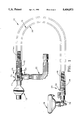
- FIG. 1 is a plan view of the breathing circuit of the present invention in its "anesthesia dispensing" mode
- FIG. 2 is an enlarged plan view of the second connector of the present invention (with the inspiratory and expiratory tubes shown in section);
- FIG. 2A is a sectional view taken along lines 2A--2A of FIG. 2 (with the inspiratory tube removed);
- FIG. 2B is a sectional view taken along lines 2B--2B of FIG. 2A;
- FIG. 3 is an enlarged-sectional view taken along the lines 3--3 of FIG. 4;
- FIG. 3A is a sectional view taken along lines 3A--3A of FIG. 1;
- FIG. 4 is plan view of an anesthesia circuit of the present invention shown in its "transport" mode of operation.
- FIG. 5 is an enlarged-sectional view taken along lines 5--5 of FIG. 4.
- a breathing circuit 10 of the present invention is shown in FIG. 1 which is especially adapted for use in a health care setting.
- breathing circuit 10 is adapted for use in connection with the dispensing of an anesthetic to a patient during surgery, and for dispensing a gas such as oxygen or air to a patient after surgery, and later for therapeutic use.
- the breathing circuit 10 includes a first end 14 which is commonly known as the "machine end" of the device 10.
- a bacterial filter 16 may be provided which prohibits the transport of bacteria across the filter 16.
- the downstream end of the bacteria filter 16 is attached to the first end 14 of the device, and the "upstream" end of the bacterial filter 16 is attached to a gas dispensing apparatus.
- the gas dispensing apparatus typically includes an inspiratory regulator (not shown) for regulating the flow of a gas from a gas storage container such as a tank (not shown) through the breathing circuit 10.
- An auxiliary expiratory tube 22 extends between the first end 14 of the device and an expiratory regulator (not shown).
- the expiratory regulator is also part of the gas dispensing apparatus, and controls the flow of expiratory gas.
- the breathing circuit 10 also includes a second end 24 which can be attached to a face mask 26, or an endotracheal tube (not shown). Face mask 26 is typically placed over the face of a patient.
- face masks include those face masks manufactured by the assignee of the instant invention, King Systems Corporation of Noblesville, Ind.
- the second end should be dimensionally compatible with common connectors.
- the breathing circuit 10 includes an expiratory tube 30 having a first end 32 disposed at the first end 14 of the device 10, and a second end 34 disposed at the second end 24 of the device 10.
- the expiratory tube 30 is preferably formed to have a corrugated structure, and is made from a flexible plastic material.
- One preferred method for manufacturing the corrugated expiratory tube 30 of the present invention is through an extrusion process.
- the expiratory tube 30 has an inner diameter of approximately 1 inch (25.4 mm).
- the breathing circuit 10 also includes a corrugated inspiratory tube 40 which is disposed generally colinearly and coaxially, with and interiorally of the expiratory tube 30.
- the inspiratory tube 40 has a first end 44 disposed adjacent to the first end 32 of the expiratory tube 30, and a second end 46 disposed adjacent to the second end 34 of the expiratory tube 30.
- a second end coupling member such as second end connector 50 is provided which is fixedly coupled to second end 34 of the expiratory tube 30, and is configured for loosely, freely, slidably receiving the second end of 46 of the inspiratory tube 40.
- the second end connector 50 is made from a plastic such as a transparent, clear rigid plastic material.
- the second connector 50 is best shown in FIGS. 2, 2A and 2B as being generally cylindrical in shape and having a radially outer surface 54 and a radially inner surface 56, a proximal end portion 58 and a distal end portion 60.
- the radially inner surface of the second end 34 of the expiratory tube 30 is sized for snugly receiving the proximal end portion 58 of the second end connector 50.
- the snug fit is designed so that during normal use of the breathing circuit 10, the second end 34 of the expiratory tube 30 will not become dislodged from the radially outer surface 54 of the second end connector 50.
- the proximal end portion of the radially inner surface 56 of the second end connector 50 functions as a positioning member receiving portion for receiving a positioning member 68 coupled to the second end 46 of the inspiratory tube 40. It includes a series of four axially extending ramps 64 which are formed thereon.
- the axially extending ramps 64 extend radially inwardly from the radially inner surface 56, such that the effective inner diameter of the interior of the proximal end portion 58 of the second end connector 50 is decreased because of the presence of the ramps 64.
- the axially extending ramps 64 include radially inwardly facing ramping surfaces 66 which are provided for receiving a positioning member 68. Positioning member 68 is best shown in FIG.
- the positioning member 68 is inserted into the interior of the second end 46 of the inspiratory tube 40 to be snugly mated to the inspiratory tube 40.
- the inspiratory tube 40 and positioning member 68 remain joined, and unseparated.
- the distal end of the positioning member 68 is received by the ramping surfaces 66 of the ramps 64, so that the positioning member 68, and (hence the second end 46 of the inspiratory tube 40) is positioned generally in the center of the interior of the proximal end portion 58 of the second end connector 50.
- the ramping surfaces 66 are formed so that the inner diameter of the second connector decreases as one moves in a direction from the proximal end portion 58 to the distal end portion 60.
- the tapered end 70 of the positioning member 68 and the ramping surfaces 66 cooperate to slidably, freely receive the positioning member 68 on the ramping surfaces 66, so that longitudinal movement of the positioning member 68 on the ramping surfaces 66 is permitted.
- the anesthesiologist it is not unusual for the anesthesiologist to manipulate and distort the circuit in a manner that will adjust the relative longitudinal positions of the second ends 46, 34 of the respective inspiratory tube 40 and expiratory tube 30.
- the positioning member 68 and thus the second end 46 of the inspiratory tube 40 may become disengaged from the ramping surfaces 66 of the ramps 64.
- the respective shape and configuration of the positioning member 68 and ramping surfaces 66 cooperate to return the positioning member 68 to its proper position on the ramping surfaces 66.
- the inspiratory tube 40 has a greater relaxed length than the expiratory tube 30.
- the inspiratory tube 40 is trapped between the first end coupling member 71 and the second end coupling member 50, and as the distance between the first end coupling member 71 and second end coupling member 50 is determined generally by the relaxed length of the expiratory tube 30, the effective longitudinal distance that can be occupied by the inspiratory tube 40 is determined largely by the relaxed length of the expiratory tube 30. Because the inspiratory tube 40 has a greater relaxed length than the expiratory tube 30, the inspiratory tube 40, under normal conditions, is not in a relaxed state when assembled into the breathing circuit 10.
- the inspiratory tube 40 exerts a longitudinal pressure on the breathing circuit 10. By exerting pressure in a longitudinal direction, the inspiratory tube 40 tends to help push the positioning member 68 toward the distal end portion 60 of the second end coupling member 50 into engagement with the ramping surfaces 66.
- the second end coupling member 50 also includes a radially extending monitoring port 72 through which internal gases can be monitored.
- the radially extending monitoring port 72 is covered by a selectively engageable cap 74.
- An elbow connector 78 (FIG. 1) is received interiorally in the distal portion 60 of the second end coupling member 50, and couples the second end coupling member 50 to the face mask 26.
- the elbow connector 78 is provided for permitting movement of the face mask 26 to enable the anesthesiologist to better position the face mask 26 on the face of the patient.
- the first end coupling member 71 is best shown in FIGS. 3 and 3A.
- the first end coupling member 71 is preferably formed of a transparent plastic material such as a rigid plastic, and is formed to be generally more rigid than either the inspiratory tube 40 or the expiratory tube 30.
- the first end coupling member 71 comprises a generally enlarged cylinder having a hollow interior, and an exterior.
- the first end coupling member 71 includes a first portion 82 which is formed separately from a second portion 84. As will be described in more detail below, the separate first portion 82 and second portion 84 are mated together and then permanently bonded together during the manufacturing process of the breathing circuit 10.
- the first portion 82 includes a first, axially extending cylindrical port 88 having a radially outer surface 90.
- the radially outer surface 90 is provided for snugly engaging the radially interior surface of the first end 32 of the expiratory tube 30.
- the engagement between the expiratory tube 30 and the first cylindrical port 88 is sufficiently snug so that during the normal useful life of the breathing circuit 10, the first cylindrical port 88 and the expiratory tube 30 do not become disengaged.
- the first portion 82 also includes a radially extending third connector port 96.
- the third radially extending connector port 96 is disposed at generally a right angle to the axially extending first cylindrical port 88.
- the third connector port 96 is in fluid communication with the interior of the first end 32 of the expiratory tube 30, so that gases flowing through the interior of the expiratory tube 30 can pass out of the expiratory tube 30, into the interior of the first end coupling 71, then through and into the third connector port 96.
- the expiratory gases passing through the third connector port 96 then pass into the auxiliary expiratory tube 22, and ultimately through the expiratory regulator (not shown).
- the first portion 71 includes a generally cylindrical rim 100 at its proximal end.
- the second portion 84 of the first coupling member 71 includes an axially extending second connector port 104 which is disposed generally colinearly with the first connector port 88.
- the second connector port 104 includes a radially inner surface 105 for receiving a mating connector port of either a bacterial filter 16 or an inspiratory regulator (not shown).
- the second portion 84 also includes an inspiratory tube connector flange 106 disposed generally colinearly with the second connector port 104.
- the inspiratory tube connector flange 106 includes a radially outer surface 108 for receiving the first end 44 of the inspiratory tube 40.
- the interior of the inspiratory tube 40 is in fluid communication with the interior of the second connector port 104, and hence the inspiratory regulator and bacteria filter 16.
- the connection between the inspiratory tube 40 and the inspiratory tube connector flange 108 is one of the most permanent connections within the breathing circuit 10, as the connection between the inspiratory tube 40 and the inspiratory tube connector flange 108 is the connection that the user would probably least likely desire to become disconnected during use.
- the second portion 84 of the first end coupling 71 also includes a first portion connector flange 112.
- the first portion connector flange 112 includes near its end a generally axially extending circular flange rim 114 which is positioned for snugly engaging the rim 100 of the first portion 82 of the first end coupling member 71.
- the circular rim 100 of the first portion 82 is placed into engagement with the flange rim 114 of the first portion connector flange 112.
- the flange rim 114 and rim 100 are then sonicly welded to each other along those surfaces at which the flange rim 114 and rim 100 intersect.
- the manufacture of the first end coupling member 71 presents a manufacturing challenge.
- a manufacturing challenge is faced to find a method for snugly engaging the first end 44 of the inspiratory tube 40 to the radially outer surface 108 of the inspiratory tube connector flange 106.
- the shape and configuration of the first end coupling member 71 makes it a part that would likely be difficult to mold.
- the applicants have devised a novel technique for manufacturing the first end coupling member 71.
- the first portion 82 is formed separately from the second portion 84.
- the first portion 82 is first molded to include the first connector port 88 for engaging the first end 32 of the expiratory tube 30.
- the first portion 82 also includes the third connector port 96 which is placed in fluid communication with the interior of the first end 32 of the expiratory tube 30.
- the second portion 84 of the first end coupling 71 is then molded to include the second connector port 104, the inspiratory tube connector flange 106, and the first portion connector flange 112, including the flange rim 114.
- the first end 44 of the inspiratory tube 40 is placed over the radially outer surface 108 of the inspiratory tube connector flange 106, and snugly engaged thereto.
- the inspiratory tube 40 is then passed through the first connector port 88, so that the rim 100 of the first portion 82 will be engaged with the flange rim 114 of the first portion connector flange 112 of the second portion 84.
- the unconnected first portion 82 can be placed over the first end 44 of the inspiratory tube 40 prior to coupling the inspiratory tube 40 to the inspiratory tube connector flange 106.
- This technique will work so long as the first portion 82 is kept separate and somewhat distant from the inspiratory tube connector flange 106 so that the first end 44 of the inspiratory tube 40 can be manipulated onto the radially outer surface 108 of the inspiratory tube connector flange 106 without interference from the first portion 82.
- first and second portions 82, 84 are then joined together. Once so joined together, the first portion 82 and second portion 84 are bonded together at the intersection between the rim 100 and the flange rim 114 of the first portion connector flange 112. Although this bonding can be performed with an adhesive such as glue, the applicants have found that the preferred method for bonding together the first portion 82 and second portion 84 is by sonic welding, thus permanently bonding the two together.
- the breathing circuit 10 of the present invention is best shown in its transport mode in FIG. 4. In the transport mode, the following parts are removed from the breathing circuit: the auxiliary expiratory tube 22, the inspiratory regulator, and the expiratory regulator. Other components are then attached to the breathing circuit 10 in place of the components that are removed. These newly added components include an inspiratory connector 120 which is provided for connecting a gas feed tube 122 to the connector port 104 of the inspiratory tube 40 of the breathing circuit 10. Other newly added components include a breathing bag connector such as expiratory connector 126, and a breathing bag 128.
- the inspiratory connector 120 is generally formed from a plastic member sized to be received interiorally by the second connector port 104 of the first end coupling member 71.
- the opposite end of the inspiratory tube connector 120 is removably engaged to a gas feed tube 122, of the type adapted for connection to an oxygen or air tank.
- gas feed tube 122 of the type adapted for connection to an oxygen or air tank.
- An example of tubing which will function as gas feed tube 122 is tygon-type tubing.
- the expiratory connector 126 is best shown in FIGS. 4 and 5 as including a first axially extending connector port 132, and a second axially extending connector port 134.
- First connector port 132 and second connector port 134 are generally disposed colinearly.
- First connector port 132 is sized and configured for receiving the radially outer surface 98 (FIG. 3) of the third connector port 96 of the first end coupling member 71 in a snug engagement.
- Second connector port 134 is provided for coupling the expiratory connector 126 to the breathing bag 128.
- the expiratory connector 126 includes a radially inner surface which defines the interior of the expiratory connector 126.
- the expiratory connector 126 also includes a radially extending exhaust port 140. Exhaust port 140 comprises an aperture formed in the sidewall of the expiratory connector 126, which leads to a generally cylindrical port-type passage.
- a valve means is shown in FIG. 5 which is provided for controlling the flow of gases through the exhaust port 140.
- the valve means comprises a cylindrical ring segment 150 having a radius of curvature only slightly smaller than the radius of curvature of the radially inner surface 138 of the expiratory connector 126. This permits the cylindrical ring segment 150 to fit snugly against the radially inner surface 138 of the expiratory connector 126.
- the cylindrical ring segment 150 includes an aperture 152 which can be aligned with the aperture of the exhaust port 140. By moving the aperture 152 of the cylindrical ring segment 150 into and out of alignment with the aperture of the exhaust port 140, the flow of gas through the exhaust port 140 can be controlled.
- the valve means also includes a knob member 154 which is disposed exteriorally of the expiratory port 126 for actuation by the user's thumb.
- the knob member 154 is connected to the cylindrical ring segment 150 by a neck 156. Lateral movement of the knob member 154 causes lateral movement of the cylindrical ring segment 150, and hence causes the aperture 150 to move into and out of engagement with the exhaust port 140.
- the breathing bag 128 includes a neck portion 156 which is sized to receive the second axially extending connector port 134 of the expiratory connector 126, and a body portion 158.
- the body portion 158 is preferably made of a stretchable, rubber-like or latex material.
- the filter 16 is coupled to the inspiratory regulator 18 and the first coupling member 71 is then coupled to the filter 16. Otherwise, the first coupling member 71 can be coupled to the inspiratory regulator 18.
- the proximal end of the auxiliary expiratory tube 22 is coupled to the third connector 96 of the first end coupling member 71, and the distal end of the auxiliary expiratory tube 22 is coupled to the expiratory regulator 20.
- the first connector 71 should already be coupled properly to the expiratory tube 30 and inspiratory tube 40.
- expiratory tube 30 and inspiratory tube 40 are already coupled at their second ends to second end coupling member 50.
- the second end coupling member 50 is then coupled to elbow connector 78 which itself is coupled to face mask 26.
- anesthesia gas will flow from its container, through the inspiratory regulator 18, through the bacteria filter 16, and into and through the inspiratory tube 40.
- the anesthesia gas Upon leaving the second end 46 of the inspiratory tube, the anesthesia gas will flow through the interior of the second connector, through the elbow connector 78 and into the face mask 26.
- the inspiratory gas does not mix with expiratory gas.
- the inspiratory and expiratory gases mix. Although this "dead space" wherein the inspiratory and expiratory gases can mix should preferably be minimized, it may be undesirable to eliminate it entirely.
- Expiratory gas is exhaled from the face mask 26, and travels through the elbow connector 78, into the interior of the second end coupling member 50, and then into the space between the inner surface of the expiratory tube 30, and the outer surface of the inspiratory tube 40.
- the expiratory gas travels along the length of the expiratory tube 30.
- the expiratory gas passes through the interior of the transparent first end coupling member 71, and then travels through the auxiliary expiratory tube 22, and through expiratory regulator 20.
- the generally enlarged size of the first end coupling member 71 when coupled with its clear plastic transparent composition, enables the practitioner to better monitor the condition of the patient's expiratory gases.
- the transition of the breathing circuit 10 from its "anesthesia" mode to the "transport” mode usually occurs at the end of an operation, when the patient is ready for being transported to a recovery room.
- the auxiliary expiratory tube 22 is disconnected at its coupling with the first end coupling member 71.
- the inspiratory regulator 18 is disconnected from the breathing filter 16, or alternately, the breathing filter 16 is disengaged from the first cylindrical port 84 of the first end coupling member 71.
- the inspiratory connector 120 and gas feed tube 122 are then coupled to the first end coupling member 71. Additionally, the expiratory connector 126 and breathing bag 128 are coupled to the third connector port 96 of the first end coupling member 71. When all of this occurs, the device is ready for use in its transport mode, offering the patient a supply of oxygen during transport, and the medical practitioner the ability to manually assist the patient's ventilation..
Landscapes
- Health & Medical Sciences (AREA)
- Emergency Medicine (AREA)
- Pulmonology (AREA)
- Engineering & Computer Science (AREA)
- Anesthesiology (AREA)
- Biomedical Technology (AREA)
- Heart & Thoracic Surgery (AREA)
- Hematology (AREA)
- Life Sciences & Earth Sciences (AREA)
- Animal Behavior & Ethology (AREA)
- General Health & Medical Sciences (AREA)
- Public Health (AREA)
- Veterinary Medicine (AREA)
- Respiratory Apparatuses And Protective Means (AREA)
Abstract
Description
Claims (17)
Priority Applications (1)
| Application Number | Priority Date | Filing Date | Title |
|---|---|---|---|
| US08/077,729 US5404873A (en) | 1993-06-16 | 1993-06-16 | Anesthesia circuit |
Applications Claiming Priority (1)
| Application Number | Priority Date | Filing Date | Title |
|---|---|---|---|
| US08/077,729 US5404873A (en) | 1993-06-16 | 1993-06-16 | Anesthesia circuit |
Publications (1)
| Publication Number | Publication Date |
|---|---|
| US5404873A true US5404873A (en) | 1995-04-11 |
Family
ID=22139724
Family Applications (1)
| Application Number | Title | Priority Date | Filing Date |
|---|---|---|---|
| US08/077,729 Expired - Lifetime US5404873A (en) | 1993-06-16 | 1993-06-16 | Anesthesia circuit |
Country Status (1)
| Country | Link |
|---|---|
| US (1) | US5404873A (en) |
Cited By (66)
| Publication number | Priority date | Publication date | Assignee | Title |
|---|---|---|---|---|
| US5582161A (en) * | 1994-12-08 | 1996-12-10 | Sherwood Medical Company | Sheathed catheter adapter and method of use |
| US5676133A (en) * | 1995-06-14 | 1997-10-14 | Apotheus Laboratories, Inc. | Expiratory scavenging method and apparatus and oxygen control system for post anesthesia care patients |
| WO1998020925A1 (en) * | 1996-11-12 | 1998-05-22 | Par Medical, Inc. | Anesthesia tube assembly |
| US5778872A (en) * | 1996-11-18 | 1998-07-14 | Medlis, Inc. | Artificial ventilation system and methods of controlling carbon dioxide rebreathing |
| US5803074A (en) * | 1996-11-25 | 1998-09-08 | Smiths Industries Medical Systems, Inc. | Valve for resuscitator apparatus |
| US5823184A (en) * | 1994-04-18 | 1998-10-20 | Tyco International (Us) Inc. | Breathing circuit |
| WO1999012598A1 (en) * | 1997-09-08 | 1999-03-18 | King Systems Corporation | Sleeved filter for a breathing circuit |
| US6003511A (en) * | 1996-11-18 | 1999-12-21 | Medlis Corp. | Respiratory circuit terminal for a unilimb respiratory device |
| EP1075849A2 (en) | 1999-08-10 | 2001-02-14 | FISHER & PAYKEL LIMITED | A ventilation system and/or breathing tube |
| US6209539B1 (en) | 1999-03-22 | 2001-04-03 | Hudson Respiratory Care Inc. | Asymmetric patient adapter for ventilator circuits |
| WO2001040050A3 (en) * | 1999-11-29 | 2001-10-25 | Maria Pfeiffer | Mouth/nose fresh air mask |
| US6378517B1 (en) * | 1999-06-02 | 2002-04-30 | DRäGER MEDIZINTECHNIK GMBH | Coupling for a breathing tube system |
| US6398266B1 (en) | 1999-09-22 | 2002-06-04 | Ballard Medical Products | Collapse resistant popoid connector |
| US6415787B1 (en) * | 1997-01-06 | 2002-07-09 | Georges Boussignac | Device for changing respiratory probes in the trachea of a patient |
| US6439231B1 (en) | 1996-11-18 | 2002-08-27 | Medlis Corp. | Artificial ventilation systems and components thereof, and methods for providing, assembling and utilizing same |
| US6463928B1 (en) * | 1999-04-06 | 2002-10-15 | Michael Irwin Buisson | Pediatric prepatory and induction anesthesia device |
| US6484724B1 (en) * | 2000-07-28 | 2002-11-26 | Ian Alexander Sloan | Universal respiratory device coupler |
| USD466607S1 (en) | 2001-08-27 | 2002-12-03 | Kimberly-Clark Worldwide, Inc. | Flexible connector |
| USD473941S1 (en) | 2001-08-27 | 2003-04-29 | Kimberly-Clark Worldwide, Inc. | Flexible connecting device |
| USD476731S1 (en) | 2001-08-27 | 2003-07-01 | Kimberly-Clark Worldwide, Inc. | Bendable connector |
| US20030183232A1 (en) * | 2001-09-24 | 2003-10-02 | Fukunaga Atsuo F. | Breathing systems with post-inspiratory valve fresh gas flow input, components for implementing same, and methods of use |
| US20030188746A1 (en) * | 2003-05-13 | 2003-10-09 | Roger Daugherty | Apparatus and method for humidification of inspired gases |
| US6631713B1 (en) * | 1996-02-26 | 2003-10-14 | Evergreen Medical Incorporated | Method and apparatus for ventilation/oxygenation during guided insertion of an endotracheal tube |
| USD486909S1 (en) | 2001-08-27 | 2004-02-17 | Kimberly-Clark Worldwide, Inc. | Bendable connecting device |
| US20040069306A1 (en) * | 2002-08-26 | 2004-04-15 | John Moenning | Dental anesthesia administration mask and eye shield |
| US20040168690A1 (en) * | 2002-12-21 | 2004-09-02 | Payne Simon Robert | Closure devices |
| US20040194781A1 (en) * | 2001-09-24 | 2004-10-07 | Fukunaga Atsuo F. | Breathing circuits having unconventional respiratory conduits and systems and methods for optimizing utilization of fresh gases |
| US20040226559A1 (en) * | 2003-05-13 | 2004-11-18 | Roger Daugherty | Apparatus and method for humidification of inspired gases |
| US20040231675A1 (en) * | 2003-05-20 | 2004-11-25 | Lyons James R. | Method and apparatus for transnasal ventilation |
| US20040239001A1 (en) * | 2001-12-14 | 2004-12-02 | Edirisuriya Deshitha Airawana | Method of forming a respiratory conduit |
| US20050039747A1 (en) * | 2001-09-24 | 2005-02-24 | Fukunaga Atsuo F. | Breathing circuits having unconventional respiratory conduits and systems and methods for optimizing utilization of fresh gases |
| US20050150505A1 (en) * | 2004-01-09 | 2005-07-14 | Burrow Kevin D. | Adjustable length breathing circuit |
| US20050178381A1 (en) * | 2003-05-13 | 2005-08-18 | Roger Daugherty | Apparatus and method for humidification of inspired gases |
| US20050188990A1 (en) * | 2004-02-12 | 2005-09-01 | Fukunaga Atsuo F. | Multifunctional integrated filter and breathing conduit |
| US20050223749A1 (en) * | 2004-04-02 | 2005-10-13 | Sung-Koog Oh | Method of fabricating an optical fiber preform and drawing of an optical fiber |
| US20070144516A1 (en) * | 2005-12-08 | 2007-06-28 | Ric Investments, Llc. | Ventilator adaptable for use with either a dual-limb circuit or a single-limb circuit |
| US20070181131A1 (en) * | 2006-02-07 | 2007-08-09 | Lowery William S | Ventilator safety coupling |
| US20070272243A1 (en) * | 2006-05-16 | 2007-11-29 | Impact Instrumentation, Inc. | Ventilator circuit for oxygen generating system |
| US20080092895A1 (en) * | 2006-10-20 | 2008-04-24 | The Metrohealth System | Manual lung ventilation device |
| WO2007102866A3 (en) * | 2005-12-08 | 2008-05-22 | Ric Investments Llc | Ventilator adaptable for use with either a dual-limb or a single-limb circuit |
| US20100132706A1 (en) * | 2007-06-01 | 2010-06-03 | Ramses Nashed | Respiratory face mask and breathing circuit assembly |
| US7753051B2 (en) | 2005-03-18 | 2010-07-13 | King Systems Corporation | Face mask strap system |
| US20100229861A1 (en) * | 2007-06-01 | 2010-09-16 | Ramses Nashed | Vacuum attachment and breathing circuit apparatus |
| US20110232639A1 (en) * | 2010-03-24 | 2011-09-29 | Harry Latshaw | Ventilation valve for a veterinary anesthesia system |
| US20120037162A1 (en) * | 2010-08-12 | 2012-02-16 | Georges Boussignac | Ventilatory assistance system |
| CN101780298B (en) * | 2009-01-20 | 2012-07-25 | 新广业股份有限公司 | Respiration tracheae assembly |
| US8726900B1 (en) * | 2010-02-01 | 2014-05-20 | Ramses Nashed | Demand anesthetic gas delivery system with disposable breathing and scavenging circuit |
| US8770199B2 (en) | 2012-12-04 | 2014-07-08 | Ino Therapeutics Llc | Cannula for minimizing dilution of dosing during nitric oxide delivery |
| WO2015187995A2 (en) | 2014-06-04 | 2015-12-10 | Revolutionary Medical Devices, Inc. | Combined nasal and mouth ventilation mask |
| WO2017026951A1 (en) * | 2015-08-13 | 2017-02-16 | Altera Medikal Tasarim Muhendislik Ve Ar-Ge Sanayi Ticaret Anonim Şirketi | Coaxial and double lumen breathing circuit systems having a lung pressure measurement port and closed system water trap which can be drained with an enjector |
| US9629975B1 (en) | 2016-09-14 | 2017-04-25 | Revolutionary Medical Devices, Inc. | Ventilation mask |
| US9782555B2 (en) | 2013-03-08 | 2017-10-10 | Teleflex Medical Incorporated | Exhalation scavenging therapy mask |
| US9795756B2 (en) | 2012-12-04 | 2017-10-24 | Mallinckrodt Hospital Products IP Limited | Cannula for minimizing dilution of dosing during nitric oxide delivery |
| USD825740S1 (en) | 2014-12-12 | 2018-08-14 | Revolutionary Medical Devices | Surgical mask |
| US10086166B1 (en) | 2010-02-01 | 2018-10-02 | Sedation Systems, Llc | Demand gas flow valve apparatus |
| WO2019007805A1 (en) * | 2017-07-03 | 2019-01-10 | Inno3 Aps | Nasal continuous positive airway pressure device and system |
| US10252016B2 (en) | 2014-08-20 | 2019-04-09 | Revolutionary Medical Devices, Inc. | Ventilation mask |
| USD848606S1 (en) | 2016-11-07 | 2019-05-14 | Revolutionary Medical Devices, Inc. | Surgical mask |
| US20190275280A1 (en) * | 2016-11-04 | 2019-09-12 | Viomedex Limited | Therapy delivery device |
| US10584811B2 (en) | 2009-12-30 | 2020-03-10 | Carl J Garrett | Tapered helically reinforced hose and its manufacture |
| US10584812B2 (en) | 2008-05-07 | 2020-03-10 | Globalmed, Inc. | Stretch hose and hose production method |
| USD898188S1 (en) | 2017-11-17 | 2020-10-06 | Revolutionary Medical Devices, Inc. | Surgical mask |
| US10792454B2 (en) | 2017-01-30 | 2020-10-06 | Globalmed, Inc. | Heated respiratory hose assembly |
| US10859188B2 (en) | 2009-01-15 | 2020-12-08 | Globalmed, Inc. | Stretch hose and hose production method |
| US11298492B2 (en) | 2016-09-14 | 2022-04-12 | Revolutionary Medical Device, Inc. | Ventilation mask |
| US11331446B2 (en) | 2015-06-11 | 2022-05-17 | Revolutionary Medical Devices, Inc. | Ventilation mask |
Citations (21)
| Publication number | Priority date | Publication date | Assignee | Title |
|---|---|---|---|---|
| US746380A (en) * | 1903-08-17 | 1903-12-08 | Frank Martin Richardson | Apparatus for administering anesthetics. |
| US3881482A (en) * | 1972-11-06 | 1975-05-06 | Octagon Med Prod | Device for moistening and heating inhalation air with tracheotomy and endotracheal intubation |
| US3889671A (en) * | 1974-02-19 | 1975-06-17 | Alfred Baker | Nasal adapter for administering analgesic gas |
| US4007737A (en) * | 1974-01-28 | 1977-02-15 | Paluch Bernard R | Anesthesia breathing system |
| GB2025239A (en) * | 1978-05-17 | 1980-01-23 | Fukunaga A F | Anaesthetic device |
| US4200094A (en) * | 1977-04-05 | 1980-04-29 | Siemens Aktiengesellschaft | Apparatus for warming and moistening a respiration gas |
| US4265235A (en) * | 1979-05-11 | 1981-05-05 | Fukunaga Atsuo F | Anesthetic system |
| US4281652A (en) * | 1978-09-07 | 1981-08-04 | Miller Donald M | Control member for anaesthesia apparatus |
| US4320754A (en) * | 1977-10-07 | 1982-03-23 | Watson Robert L | Controllable partial rebreathing anesthesia circuit and respiratory assist device |
| US4430994A (en) * | 1981-05-11 | 1984-02-14 | Clawson Burrell E | Respiratory gas heating and humidifying methods and apparatus |
| US4440163A (en) * | 1982-07-30 | 1984-04-03 | Gabriel Spergel | Emergency escape breathing apparatus |
| US4463755A (en) * | 1981-05-18 | 1984-08-07 | Terumo Corporation | Breathing circuit |
| US4521038A (en) * | 1983-05-20 | 1985-06-04 | Respiratory Care, Inc. | Safety connector for flexible tube device |
| US4637384A (en) * | 1985-02-15 | 1987-01-20 | The Boc Group, Inc. | Coaxial breathing circuit |
| US4676239A (en) * | 1980-09-20 | 1987-06-30 | David Humphrey | Anesthetic system |
| US4682010A (en) * | 1983-03-07 | 1987-07-21 | Safeway Products, Inc. | In-line electric heater for an aerosol delivery system |
| US4686354A (en) * | 1985-04-04 | 1987-08-11 | The Boc Group Plc | Inhalation apparatus |
| US4825859A (en) * | 1987-03-11 | 1989-05-02 | Ballard Medical Products | Neonatal closed system for involuntary aspiration and ventilation and method |
| US5140983A (en) * | 1990-04-11 | 1992-08-25 | Jinotti Walter J | Multi purpose catheter assembly |
| US5176150A (en) * | 1992-05-08 | 1993-01-05 | Hartwig Ricky G | Laparoscopic esophageal gastric apparatus |
| US5284160A (en) * | 1991-11-13 | 1994-02-08 | Dryden Gale E | Consolidated anesthesia circuit |
-
1993
- 1993-06-16 US US08/077,729 patent/US5404873A/en not_active Expired - Lifetime
Patent Citations (21)
| Publication number | Priority date | Publication date | Assignee | Title |
|---|---|---|---|---|
| US746380A (en) * | 1903-08-17 | 1903-12-08 | Frank Martin Richardson | Apparatus for administering anesthetics. |
| US3881482A (en) * | 1972-11-06 | 1975-05-06 | Octagon Med Prod | Device for moistening and heating inhalation air with tracheotomy and endotracheal intubation |
| US4007737A (en) * | 1974-01-28 | 1977-02-15 | Paluch Bernard R | Anesthesia breathing system |
| US3889671A (en) * | 1974-02-19 | 1975-06-17 | Alfred Baker | Nasal adapter for administering analgesic gas |
| US4200094A (en) * | 1977-04-05 | 1980-04-29 | Siemens Aktiengesellschaft | Apparatus for warming and moistening a respiration gas |
| US4320754A (en) * | 1977-10-07 | 1982-03-23 | Watson Robert L | Controllable partial rebreathing anesthesia circuit and respiratory assist device |
| GB2025239A (en) * | 1978-05-17 | 1980-01-23 | Fukunaga A F | Anaesthetic device |
| US4281652A (en) * | 1978-09-07 | 1981-08-04 | Miller Donald M | Control member for anaesthesia apparatus |
| US4265235A (en) * | 1979-05-11 | 1981-05-05 | Fukunaga Atsuo F | Anesthetic system |
| US4676239A (en) * | 1980-09-20 | 1987-06-30 | David Humphrey | Anesthetic system |
| US4430994A (en) * | 1981-05-11 | 1984-02-14 | Clawson Burrell E | Respiratory gas heating and humidifying methods and apparatus |
| US4463755A (en) * | 1981-05-18 | 1984-08-07 | Terumo Corporation | Breathing circuit |
| US4440163A (en) * | 1982-07-30 | 1984-04-03 | Gabriel Spergel | Emergency escape breathing apparatus |
| US4682010A (en) * | 1983-03-07 | 1987-07-21 | Safeway Products, Inc. | In-line electric heater for an aerosol delivery system |
| US4521038A (en) * | 1983-05-20 | 1985-06-04 | Respiratory Care, Inc. | Safety connector for flexible tube device |
| US4637384A (en) * | 1985-02-15 | 1987-01-20 | The Boc Group, Inc. | Coaxial breathing circuit |
| US4686354A (en) * | 1985-04-04 | 1987-08-11 | The Boc Group Plc | Inhalation apparatus |
| US4825859A (en) * | 1987-03-11 | 1989-05-02 | Ballard Medical Products | Neonatal closed system for involuntary aspiration and ventilation and method |
| US5140983A (en) * | 1990-04-11 | 1992-08-25 | Jinotti Walter J | Multi purpose catheter assembly |
| US5284160A (en) * | 1991-11-13 | 1994-02-08 | Dryden Gale E | Consolidated anesthesia circuit |
| US5176150A (en) * | 1992-05-08 | 1993-01-05 | Hartwig Ricky G | Laparoscopic esophageal gastric apparatus |
Cited By (119)
| Publication number | Priority date | Publication date | Assignee | Title |
|---|---|---|---|---|
| US5823184A (en) * | 1994-04-18 | 1998-10-20 | Tyco International (Us) Inc. | Breathing circuit |
| US5582161A (en) * | 1994-12-08 | 1996-12-10 | Sherwood Medical Company | Sheathed catheter adapter and method of use |
| US5676133A (en) * | 1995-06-14 | 1997-10-14 | Apotheus Laboratories, Inc. | Expiratory scavenging method and apparatus and oxygen control system for post anesthesia care patients |
| US6631713B1 (en) * | 1996-02-26 | 2003-10-14 | Evergreen Medical Incorporated | Method and apparatus for ventilation/oxygenation during guided insertion of an endotracheal tube |
| US5901705A (en) * | 1996-10-17 | 1999-05-11 | King Systems Corporation | Sleeved filter for a breathing circuit |
| US5894839A (en) * | 1996-11-12 | 1999-04-20 | Par Medical, Inc. | Anesthesia tube assembly |
| WO1998020925A1 (en) * | 1996-11-12 | 1998-05-22 | Par Medical, Inc. | Anesthesia tube assembly |
| US6439231B1 (en) | 1996-11-18 | 2002-08-27 | Medlis Corp. | Artificial ventilation systems and components thereof, and methods for providing, assembling and utilizing same |
| US5778872A (en) * | 1996-11-18 | 1998-07-14 | Medlis, Inc. | Artificial ventilation system and methods of controlling carbon dioxide rebreathing |
| US5983891A (en) * | 1996-11-18 | 1999-11-16 | Medlis Corp. | Artificial ventilation methods for controlling carbon dioxide rebreathing |
| US5983894A (en) * | 1996-11-18 | 1999-11-16 | Medlis Corporation | Filter for a unilimb rebreathing ventilator |
| US5983896A (en) * | 1996-11-18 | 1999-11-16 | Medlis Corporation | Respiratory conduit for a unilimb respiratory device |
| US6003511A (en) * | 1996-11-18 | 1999-12-21 | Medlis Corp. | Respiratory circuit terminal for a unilimb respiratory device |
| US20050022828A1 (en) * | 1996-11-18 | 2005-02-03 | Fukunaga Atsuo F. | Multilumen unilimb breathing circuit with detachable proximal fitting |
| US7418965B2 (en) * | 1996-11-18 | 2008-09-02 | Medlis Corp. | Multilumen unilimb breathing circuit with detachable proximal fitting |
| US6564799B2 (en) | 1996-11-18 | 2003-05-20 | Medlis Corp. | Multilumen filter |
| US5803074A (en) * | 1996-11-25 | 1998-09-08 | Smiths Industries Medical Systems, Inc. | Valve for resuscitator apparatus |
| US6415787B1 (en) * | 1997-01-06 | 2002-07-09 | Georges Boussignac | Device for changing respiratory probes in the trachea of a patient |
| AU730585B2 (en) * | 1997-09-08 | 2001-03-08 | King Systems Corporation | Sleeved filter for a breathing circuit |
| WO1999012598A1 (en) * | 1997-09-08 | 1999-03-18 | King Systems Corporation | Sleeved filter for a breathing circuit |
| US6129082A (en) * | 1997-09-08 | 2000-10-10 | King Systems Corporation | Sleeved filter for a breathing circuit |
| US6209539B1 (en) | 1999-03-22 | 2001-04-03 | Hudson Respiratory Care Inc. | Asymmetric patient adapter for ventilator circuits |
| US6463928B1 (en) * | 1999-04-06 | 2002-10-15 | Michael Irwin Buisson | Pediatric prepatory and induction anesthesia device |
| US6378517B1 (en) * | 1999-06-02 | 2002-04-30 | DRäGER MEDIZINTECHNIK GMBH | Coupling for a breathing tube system |
| US6536428B1 (en) | 1999-08-10 | 2003-03-25 | Fisher & Paykel Limited | Ventilation system and/or breathing tube |
| EP1075849A2 (en) | 1999-08-10 | 2001-02-14 | FISHER & PAYKEL LIMITED | A ventilation system and/or breathing tube |
| US6398266B1 (en) | 1999-09-22 | 2002-06-04 | Ballard Medical Products | Collapse resistant popoid connector |
| WO2001040050A3 (en) * | 1999-11-29 | 2001-10-25 | Maria Pfeiffer | Mouth/nose fresh air mask |
| US6484724B1 (en) * | 2000-07-28 | 2002-11-26 | Ian Alexander Sloan | Universal respiratory device coupler |
| USD476731S1 (en) | 2001-08-27 | 2003-07-01 | Kimberly-Clark Worldwide, Inc. | Bendable connector |
| USD473941S1 (en) | 2001-08-27 | 2003-04-29 | Kimberly-Clark Worldwide, Inc. | Flexible connecting device |
| USD466607S1 (en) | 2001-08-27 | 2002-12-03 | Kimberly-Clark Worldwide, Inc. | Flexible connector |
| USD486909S1 (en) | 2001-08-27 | 2004-02-17 | Kimberly-Clark Worldwide, Inc. | Bendable connecting device |
| US7275541B2 (en) | 2001-09-24 | 2007-10-02 | F-Concepts Llc | Breathing circuits having unconventional respiratory conduits and systems and methods for optimizing utilization of fresh gases |
| US20040194781A1 (en) * | 2001-09-24 | 2004-10-07 | Fukunaga Atsuo F. | Breathing circuits having unconventional respiratory conduits and systems and methods for optimizing utilization of fresh gases |
| US7261105B2 (en) | 2001-09-24 | 2007-08-28 | F-Concepts Llc | Breathing circuits having unconventional respiratory conduits and systems and methods for optimizing utilization of fresh gases |
| US20050039747A1 (en) * | 2001-09-24 | 2005-02-24 | Fukunaga Atsuo F. | Breathing circuits having unconventional respiratory conduits and systems and methods for optimizing utilization of fresh gases |
| US6874500B2 (en) | 2001-09-24 | 2005-04-05 | Atsuo F. Fukunaga | Breathing circuits having unconventional respiratory conduits and systems and methods for optimizing utilization of fresh gases |
| US7717109B2 (en) | 2001-09-24 | 2010-05-18 | F-Concepts Llc | Breathing systems with post-inspiratory valve fresh gas flow input, components for implementing same, and methods of use |
| US20030183232A1 (en) * | 2001-09-24 | 2003-10-02 | Fukunaga Atsuo F. | Breathing systems with post-inspiratory valve fresh gas flow input, components for implementing same, and methods of use |
| US20040239001A1 (en) * | 2001-12-14 | 2004-12-02 | Edirisuriya Deshitha Airawana | Method of forming a respiratory conduit |
| US20040069306A1 (en) * | 2002-08-26 | 2004-04-15 | John Moenning | Dental anesthesia administration mask and eye shield |
| US7243649B2 (en) | 2002-08-26 | 2007-07-17 | King Systems Corporation | Anesthesia administration mask and eye shield |
| US20040168690A1 (en) * | 2002-12-21 | 2004-09-02 | Payne Simon Robert | Closure devices |
| US7370653B2 (en) * | 2002-12-21 | 2008-05-13 | Intersurgical Ag | Closure devices for access ports of respiratory apparatuses |
| US7007691B2 (en) * | 2003-05-13 | 2006-03-07 | Roger Daugherty | Apparatus and method for humidification of inspired gases |
| US20060037610A1 (en) * | 2003-05-13 | 2006-02-23 | Roger Daugherty | Apparatus and method for humidification of inspired gases |
| US20060037609A1 (en) * | 2003-05-13 | 2006-02-23 | Roger Daugherty | Apparatus and method for humidification of inspired gases |
| US20030188746A1 (en) * | 2003-05-13 | 2003-10-09 | Roger Daugherty | Apparatus and method for humidification of inspired gases |
| US20050178381A1 (en) * | 2003-05-13 | 2005-08-18 | Roger Daugherty | Apparatus and method for humidification of inspired gases |
| US20040226559A1 (en) * | 2003-05-13 | 2004-11-18 | Roger Daugherty | Apparatus and method for humidification of inspired gases |
| US20040231675A1 (en) * | 2003-05-20 | 2004-11-25 | Lyons James R. | Method and apparatus for transnasal ventilation |
| EP1706163A4 (en) * | 2004-01-09 | 2010-04-21 | King Systems Corp | Adjustable length breathing circuit |
| EP1706163A2 (en) * | 2004-01-09 | 2006-10-04 | King Systems Corporation | Adjustable length breathing circuit |
| US7178521B2 (en) | 2004-01-09 | 2007-02-20 | King Systems Corporation | Adjustable length breathing circuit |
| US20050150505A1 (en) * | 2004-01-09 | 2005-07-14 | Burrow Kevin D. | Adjustable length breathing circuit |
| US20050188990A1 (en) * | 2004-02-12 | 2005-09-01 | Fukunaga Atsuo F. | Multifunctional integrated filter and breathing conduit |
| US20050223749A1 (en) * | 2004-04-02 | 2005-10-13 | Sung-Koog Oh | Method of fabricating an optical fiber preform and drawing of an optical fiber |
| US7753051B2 (en) | 2005-03-18 | 2010-07-13 | King Systems Corporation | Face mask strap system |
| WO2007102866A3 (en) * | 2005-12-08 | 2008-05-22 | Ric Investments Llc | Ventilator adaptable for use with either a dual-limb or a single-limb circuit |
| US7617824B2 (en) * | 2005-12-08 | 2009-11-17 | Ric Investments, Llc | Ventilator adaptable for use with either a dual-limb circuit or a single-limb circuit |
| US20070144516A1 (en) * | 2005-12-08 | 2007-06-28 | Ric Investments, Llc. | Ventilator adaptable for use with either a dual-limb circuit or a single-limb circuit |
| US20070181131A1 (en) * | 2006-02-07 | 2007-08-09 | Lowery William S | Ventilator safety coupling |
| US20070272243A1 (en) * | 2006-05-16 | 2007-11-29 | Impact Instrumentation, Inc. | Ventilator circuit for oxygen generating system |
| US8667963B2 (en) * | 2006-05-16 | 2014-03-11 | Impact Instrumentation, Inc. | Ventilator circuit for oxygen generating system |
| US8651107B2 (en) * | 2006-10-20 | 2014-02-18 | The Metrohealth System | Manual lung ventilation device |
| US20080092895A1 (en) * | 2006-10-20 | 2008-04-24 | The Metrohealth System | Manual lung ventilation device |
| US20100229861A1 (en) * | 2007-06-01 | 2010-09-16 | Ramses Nashed | Vacuum attachment and breathing circuit apparatus |
| US10722674B2 (en) * | 2007-06-01 | 2020-07-28 | Sedation Systems, Llc | Respiratory face mask and breathing circuit assembly |
| US20100132706A1 (en) * | 2007-06-01 | 2010-06-03 | Ramses Nashed | Respiratory face mask and breathing circuit assembly |
| US8550076B2 (en) * | 2007-06-01 | 2013-10-08 | Ramses Nashed | Vacuum attachment and breathing circuit apparatus |
| US20170072156A1 (en) * | 2007-06-01 | 2017-03-16 | Ramses Nashed | Respiratory face mask and breathing circuit assembly |
| US20140373841A1 (en) * | 2007-06-01 | 2014-12-25 | Ramses Nashed | Respiratory face mask and breathing circuit assembly |
| US8826905B2 (en) * | 2007-06-01 | 2014-09-09 | Ramses Nashed | Respiratory face mask and breathing circuit assembly |
| US10584812B2 (en) | 2008-05-07 | 2020-03-10 | Globalmed, Inc. | Stretch hose and hose production method |
| US10859188B2 (en) | 2009-01-15 | 2020-12-08 | Globalmed, Inc. | Stretch hose and hose production method |
| CN101780298B (en) * | 2009-01-20 | 2012-07-25 | 新广业股份有限公司 | Respiration tracheae assembly |
| US10584811B2 (en) | 2009-12-30 | 2020-03-10 | Carl J Garrett | Tapered helically reinforced hose and its manufacture |
| US11110247B1 (en) | 2010-02-01 | 2021-09-07 | Sedation Systems, Llc | Demand gas flow valve apparatus |
| US8726900B1 (en) * | 2010-02-01 | 2014-05-20 | Ramses Nashed | Demand anesthetic gas delivery system with disposable breathing and scavenging circuit |
| US10086166B1 (en) | 2010-02-01 | 2018-10-02 | Sedation Systems, Llc | Demand gas flow valve apparatus |
| AU2011209931B2 (en) * | 2010-02-01 | 2015-06-18 | Ramses Nashed | Respiratory face mask and breathing circuit assembly |
| US8925547B2 (en) | 2010-03-24 | 2015-01-06 | Harry Latshaw | Ventilation valve for an anesthesia system |
| US20110232639A1 (en) * | 2010-03-24 | 2011-09-29 | Harry Latshaw | Ventilation valve for a veterinary anesthesia system |
| US20120037162A1 (en) * | 2010-08-12 | 2012-02-16 | Georges Boussignac | Ventilatory assistance system |
| US10130783B2 (en) | 2012-12-04 | 2018-11-20 | Mallinckrodt Hospital Products IP Limited | Cannula for minimizing dilution of dosing during nitric oxide delivery |
| US9550039B2 (en) | 2012-12-04 | 2017-01-24 | Mallinckrodt Hospital Products IP Limited | Cannula for minimizing dilution of dosing during nitric oxide delivery |
| US10918819B2 (en) | 2012-12-04 | 2021-02-16 | Mallinckrodt Hospital Products IP Limited | Cannula for minimizing dilution of dosing during nitric oxide delivery |
| US9032959B2 (en) | 2012-12-04 | 2015-05-19 | Ino Therapeutics Llc | Cannula for minimizing dilution of dosing during nitric oxide delivery |
| US9795756B2 (en) | 2012-12-04 | 2017-10-24 | Mallinckrodt Hospital Products IP Limited | Cannula for minimizing dilution of dosing during nitric oxide delivery |
| US8770199B2 (en) | 2012-12-04 | 2014-07-08 | Ino Therapeutics Llc | Cannula for minimizing dilution of dosing during nitric oxide delivery |
| US10556082B2 (en) | 2012-12-04 | 2020-02-11 | Mallinckrodt Hospital Products IP Limited | Cannula for minimizing dilution of dosing during nitric oxide delivery |
| US9782555B2 (en) | 2013-03-08 | 2017-10-10 | Teleflex Medical Incorporated | Exhalation scavenging therapy mask |
| WO2015187995A2 (en) | 2014-06-04 | 2015-12-10 | Revolutionary Medical Devices, Inc. | Combined nasal and mouth ventilation mask |
| EP3689183A1 (en) | 2014-06-04 | 2020-08-05 | Revolutionary Medical Devices, Inc. | Combined nasal and mouth ventilation mask |
| US10589047B2 (en) | 2014-06-04 | 2020-03-17 | Revolutionary Medical Devices, Inc. | Combined nasal and mouth ventilation mask |
| US10252016B2 (en) | 2014-08-20 | 2019-04-09 | Revolutionary Medical Devices, Inc. | Ventilation mask |
| US11324909B2 (en) | 2014-08-20 | 2022-05-10 | Revolutionary Medical Devices, Inc. | Ventilation mask |
| USD862687S1 (en) | 2014-12-12 | 2019-10-08 | Revolutionary Medical Devices, Inc. | Surgical mask |
| USD993394S1 (en) | 2014-12-12 | 2023-07-25 | Sunmed Group Holdings, Llc | Surgical mask |
| USD976393S1 (en) | 2014-12-12 | 2023-01-24 | Revolutionary Medical Devices, Inc. | Surgical mask |
| USD825740S1 (en) | 2014-12-12 | 2018-08-14 | Revolutionary Medical Devices | Surgical mask |
| US11813402B2 (en) | 2015-06-11 | 2023-11-14 | Sunmed Group Holdings, Llc | Ventilation mask |
| US11331446B2 (en) | 2015-06-11 | 2022-05-17 | Revolutionary Medical Devices, Inc. | Ventilation mask |
| WO2017026951A1 (en) * | 2015-08-13 | 2017-02-16 | Altera Medikal Tasarim Muhendislik Ve Ar-Ge Sanayi Ticaret Anonim Şirketi | Coaxial and double lumen breathing circuit systems having a lung pressure measurement port and closed system water trap which can be drained with an enjector |
| US11395896B2 (en) | 2015-08-13 | 2022-07-26 | Atilla SEVINCLI | Coaxial and double lumen breathing circuit systems having a lung pressure measurement port and closed system water trap which can be drained with an enjector |
| EA036901B1 (en) * | 2015-08-13 | 2021-01-13 | Алтера Тыббы Малземе Санайи Ве Тыджарет Аноным Шыркеты | Closed system water trap and double lumen breathing circuit and coaxial breathing circuit having such water trap |
| US9629975B1 (en) | 2016-09-14 | 2017-04-25 | Revolutionary Medical Devices, Inc. | Ventilation mask |
| US11298492B2 (en) | 2016-09-14 | 2022-04-12 | Revolutionary Medical Device, Inc. | Ventilation mask |
| US20190275280A1 (en) * | 2016-11-04 | 2019-09-12 | Viomedex Limited | Therapy delivery device |
| US11918744B2 (en) * | 2016-11-04 | 2024-03-05 | Viomedex Limited | Therapy delivery device |
| USD929572S1 (en) | 2016-11-07 | 2021-08-31 | Revolutionary Medical Devices, Inc. | Surgical mask |
| USD892306S1 (en) | 2016-11-07 | 2020-08-04 | Revolutionary Medical Devices, Inc. | Surgical mask |
| USD848606S1 (en) | 2016-11-07 | 2019-05-14 | Revolutionary Medical Devices, Inc. | Surgical mask |
| US11052214B2 (en) | 2017-01-30 | 2021-07-06 | Globalmed, Inc. | Heated respiratory hose wiring |
| US10792454B2 (en) | 2017-01-30 | 2020-10-06 | Globalmed, Inc. | Heated respiratory hose assembly |
| WO2019007805A1 (en) * | 2017-07-03 | 2019-01-10 | Inno3 Aps | Nasal continuous positive airway pressure device and system |
| USD898188S1 (en) | 2017-11-17 | 2020-10-06 | Revolutionary Medical Devices, Inc. | Surgical mask |
| USD930151S1 (en) | 2017-11-17 | 2021-09-07 | Revolutionary Medical Devices, Inc. | Surgical mask |
Similar Documents
| Publication | Publication Date | Title |
|---|---|---|
| US5404873A (en) | Anesthesia circuit | |
| CN100512910C (en) | Breathing circuits having unconventional respiratory conduits and systems and methods for optimizing utilization of fresh gases | |
| US4360018A (en) | Anesthesia system and method of filtering respiratory gas | |
| CA2231813C (en) | Disposable oxygenating device | |
| US5357946A (en) | Ventilator manifold with accessory access port and adaptors therefore | |
| US20050188990A1 (en) | Multifunctional integrated filter and breathing conduit | |
| US5343857A (en) | Respiratory accessory access port and adaptor therefore | |
| US5121746A (en) | Anaesthetic and respirator breathing circuit device | |
| AU2001278321B2 (en) | Universal respiratory device coupler | |
| US3713440A (en) | Filtration system | |
| US7147252B2 (en) | Medical connector | |
| EP0992259B1 (en) | A connector, in particular for use in a breathing circuit | |
| US3856051A (en) | Flexible tube device | |
| US5628306A (en) | Respiratory manifold with accessory access port | |
| US4351328A (en) | Simultaneous respiration and endotracheal suctioning of a critically ill patient | |
| US4521038A (en) | Safety connector for flexible tube device | |
| EP2272557A2 (en) | Suction catheter assembly | |
| AU2002245200A1 (en) | Suction catheter assembly | |
| US20230330376A1 (en) | Respiratory valve apparatus and related methods | |
| EP1621224A2 (en) | Breathing circuit having an adjustable volume and length | |
| US6041781A (en) | Breathing bag | |
| US8281785B2 (en) | Breathing system | |
| CN213554174U (en) | Gastric content suction tube | |
| CN211096834U (en) | Disposable trachea cannula inner limiting device | |
| CA2767462C (en) | Breathing circuits having unconventional respiratory conduits and systems and methods for optimizing utilization of fresh gases |
Legal Events
| Date | Code | Title | Description |
|---|---|---|---|
| AS | Assignment |
Owner name: KING SYSTEMS CORPORATION DIVISION OF BURCO MOLDING Free format text: ASSIGNMENT OF ASSIGNORS INTEREST;ASSIGNORS:LEAGRE, MICHAEL A.;BURROW, KEVIN D.;REEL/FRAME:006620/0020 Effective date: 19930607 |
|
| AS | Assignment |
Owner name: KING SYSTEMS CORPORATION, INDIANA Free format text: ASSIGNMENT OF ASSIGNORS INTEREST;ASSIGNOR:KING SYSTEMS CORPORATION DIVISION OF BURCO MOLDING, INC.;REEL/FRAME:007558/0125 Effective date: 19950523 |
|
| CC | Certificate of correction | ||
| FPAY | Fee payment |
Year of fee payment: 4 |
|
| AS | Assignment |
Owner name: MEDLIS CORPORATION, CALIFORNIA Free format text: ASSIGNMENT OF ASSIGNORS INTEREST;ASSIGNOR:KINGS SYSTEMS CORPORATION;REEL/FRAME:009547/0904 Effective date: 19981014 Owner name: MEDLIS CORPORATION, CALIFORNIA Free format text: ASSIGNMENT OF ASSIGNORS INTEREST;ASSIGNOR:FUKUNAGA, ATSUO F.;REEL/FRAME:009556/0656 Effective date: 19980923 |
|
| STPP | Information on status: patent application and granting procedure in general |
Free format text: APPLICATION UNDERGOING PREEXAM PROCESSING |
|
| CC | Certificate of correction | ||
| FPAY | Fee payment |
Year of fee payment: 8 |
|
| FEPP | Fee payment procedure |
Free format text: PAT HOLDER NO LONGER CLAIMS SMALL ENTITY STATUS, ENTITY STATUS SET TO UNDISCOUNTED (ORIGINAL EVENT CODE: STOL); ENTITY STATUS OF PATENT OWNER: LARGE ENTITY |
|
| REFU | Refund |
Free format text: REFUND - PAYMENT OF MAINTENANCE FEE, 12TH YR, SMALL ENTITY (ORIGINAL EVENT CODE: R2553); ENTITY STATUS OF PATENT OWNER: LARGE ENTITY |
|
| FPAY | Fee payment |
Year of fee payment: 12 |
|
| AS | Assignment |
Owner name: AMBU A/S, DENMARK Free format text: ASSIGNMENT OF ASSIGNORS INTEREST;ASSIGNOR:MEDLIS CORP.;REEL/FRAME:038607/0890 Effective date: 20160329 |