JP2006304307A - Method for adaptively selecting context model for entropy coding and video decoder - Google Patents
Method for adaptively selecting context model for entropy coding and video decoder Download PDFInfo
- Publication number
- JP2006304307A JP2006304307A JP2006114648A JP2006114648A JP2006304307A JP 2006304307 A JP2006304307 A JP 2006304307A JP 2006114648 A JP2006114648 A JP 2006114648A JP 2006114648 A JP2006114648 A JP 2006114648A JP 2006304307 A JP2006304307 A JP 2006304307A
- Authority
- JP
- Japan
- Prior art keywords
- data
- residual
- decoding
- prediction flag
- value
- Prior art date
- Legal status (The legal status is an assumption and is not a legal conclusion. Google has not performed a legal analysis and makes no representation as to the accuracy of the status listed.)
- Pending
Links
Images


Classifications
-
- H—ELECTRICITY
- H04—ELECTRIC COMMUNICATION TECHNIQUE
- H04N—PICTORIAL COMMUNICATION, e.g. TELEVISION
- H04N19/00—Methods or arrangements for coding, decoding, compressing or decompressing digital video signals
- H04N19/30—Methods or arrangements for coding, decoding, compressing or decompressing digital video signals using hierarchical techniques, e.g. scalability
- H04N19/34—Scalability techniques involving progressive bit-plane based encoding of the enhancement layer, e.g. fine granular scalability [FGS]
-
- H—ELECTRICITY
- H04—ELECTRIC COMMUNICATION TECHNIQUE
- H04N—PICTORIAL COMMUNICATION, e.g. TELEVISION
- H04N19/00—Methods or arrangements for coding, decoding, compressing or decompressing digital video signals
- H04N19/10—Methods or arrangements for coding, decoding, compressing or decompressing digital video signals using adaptive coding
- H04N19/102—Methods or arrangements for coding, decoding, compressing or decompressing digital video signals using adaptive coding characterised by the element, parameter or selection affected or controlled by the adaptive coding
- H04N19/13—Adaptive entropy coding, e.g. adaptive variable length coding [AVLC] or context adaptive binary arithmetic coding [CABAC]
-
- H—ELECTRICITY
- H04—ELECTRIC COMMUNICATION TECHNIQUE
- H04N—PICTORIAL COMMUNICATION, e.g. TELEVISION
- H04N19/00—Methods or arrangements for coding, decoding, compressing or decompressing digital video signals
- H04N19/10—Methods or arrangements for coding, decoding, compressing or decompressing digital video signals using adaptive coding
- H04N19/134—Methods or arrangements for coding, decoding, compressing or decompressing digital video signals using adaptive coding characterised by the element, parameter or criterion affecting or controlling the adaptive coding
- H04N19/136—Incoming video signal characteristics or properties
- H04N19/137—Motion inside a coding unit, e.g. average field, frame or block difference
- H04N19/139—Analysis of motion vectors, e.g. their magnitude, direction, variance or reliability
-
- H—ELECTRICITY
- H04—ELECTRIC COMMUNICATION TECHNIQUE
- H04N—PICTORIAL COMMUNICATION, e.g. TELEVISION
- H04N19/00—Methods or arrangements for coding, decoding, compressing or decompressing digital video signals
- H04N19/10—Methods or arrangements for coding, decoding, compressing or decompressing digital video signals using adaptive coding
- H04N19/134—Methods or arrangements for coding, decoding, compressing or decompressing digital video signals using adaptive coding characterised by the element, parameter or criterion affecting or controlling the adaptive coding
- H04N19/136—Incoming video signal characteristics or properties
- H04N19/14—Coding unit complexity, e.g. amount of activity or edge presence estimation
-
- H—ELECTRICITY
- H04—ELECTRIC COMMUNICATION TECHNIQUE
- H04N—PICTORIAL COMMUNICATION, e.g. TELEVISION
- H04N19/00—Methods or arrangements for coding, decoding, compressing or decompressing digital video signals
- H04N19/10—Methods or arrangements for coding, decoding, compressing or decompressing digital video signals using adaptive coding
- H04N19/169—Methods or arrangements for coding, decoding, compressing or decompressing digital video signals using adaptive coding characterised by the coding unit, i.e. the structural portion or semantic portion of the video signal being the object or the subject of the adaptive coding
- H04N19/17—Methods or arrangements for coding, decoding, compressing or decompressing digital video signals using adaptive coding characterised by the coding unit, i.e. the structural portion or semantic portion of the video signal being the object or the subject of the adaptive coding the unit being an image region, e.g. an object
- H04N19/176—Methods or arrangements for coding, decoding, compressing or decompressing digital video signals using adaptive coding characterised by the coding unit, i.e. the structural portion or semantic portion of the video signal being the object or the subject of the adaptive coding the unit being an image region, e.g. an object the region being a block, e.g. a macroblock
-
- H—ELECTRICITY
- H04—ELECTRIC COMMUNICATION TECHNIQUE
- H04N—PICTORIAL COMMUNICATION, e.g. TELEVISION
- H04N19/00—Methods or arrangements for coding, decoding, compressing or decompressing digital video signals
- H04N19/10—Methods or arrangements for coding, decoding, compressing or decompressing digital video signals using adaptive coding
- H04N19/189—Methods or arrangements for coding, decoding, compressing or decompressing digital video signals using adaptive coding characterised by the adaptation method, adaptation tool or adaptation type used for the adaptive coding
- H04N19/196—Methods or arrangements for coding, decoding, compressing or decompressing digital video signals using adaptive coding characterised by the adaptation method, adaptation tool or adaptation type used for the adaptive coding being specially adapted for the computation of encoding parameters, e.g. by averaging previously computed encoding parameters
-
- H—ELECTRICITY
- H04—ELECTRIC COMMUNICATION TECHNIQUE
- H04N—PICTORIAL COMMUNICATION, e.g. TELEVISION
- H04N19/00—Methods or arrangements for coding, decoding, compressing or decompressing digital video signals
- H04N19/46—Embedding additional information in the video signal during the compression process
- H04N19/463—Embedding additional information in the video signal during the compression process by compressing encoding parameters before transmission
-
- H—ELECTRICITY
- H04—ELECTRIC COMMUNICATION TECHNIQUE
- H04N—PICTORIAL COMMUNICATION, e.g. TELEVISION
- H04N19/00—Methods or arrangements for coding, decoding, compressing or decompressing digital video signals
- H04N19/70—Methods or arrangements for coding, decoding, compressing or decompressing digital video signals characterised by syntax aspects related to video coding, e.g. related to compression standards
Abstract
Description
本発明は、ビデオ信号のエンコーディング及びデコーディングに係り、より詳細には、エントロピーコーディングのコンテキストモデルを適応的に選択する方法及びビデオデコーダに関する。 The present invention relates to encoding and decoding of video signals, and more particularly, to a method and video decoder for adaptively selecting a context model for entropy coding.
インターネットを含む情報通信技術が発達するにつれて文字、音声だけでなく画像通信が増加しつつある。既存の文字中心の通信方式では消費者の多様な欲求を満たすには足りなく、したがって、文字、映像、音楽など多様な形態の情報を収容できるマルチメディアサービスが増加しつつある。マルチメディアデータは、その量がぼう大で大容量の記録媒体を必要とし、伝送時に広い帯域幅を必要とする。したがって、文字、映像、オーディオを含むマルチメディアデータを伝送するには、圧縮コーディング技法を使用することが必須である。 As information communication technology including the Internet develops, not only text and voice but also image communication is increasing. Existing character-centric communication methods are not sufficient to satisfy the diverse needs of consumers, and therefore, multimedia services that can accommodate various forms of information such as characters, video, and music are increasing. Multimedia data requires a large amount and a large capacity recording medium, and requires a wide bandwidth during transmission. Therefore, it is essential to use compression coding techniques to transmit multimedia data including characters, video, and audio.
データを圧縮する基本的な原理はデータの重複をなくす過程である。イメージで同じ色や客体が反復されるような空間的重複や、動映像フレームで隣接フレームがほとんど変化のない場合や、オーディオで同じ音が反復され続けるような時間的重複、または人間の視覚及び知覚能力が高い周波数に鈍感なことを考慮した心理視覚重複をなくすことによりデータを圧縮できる。一般的なビデオコーディング方法において、時間的重畳はモーション補償に基づいた時間的フィルタリング(temporal filtering)により除去して、空間的重畳は空間的変換(spatial transform)により除去する。 The basic principle of data compression is the process of eliminating data duplication. Spatial overlap where the same color and object are repeated in the image, if there is almost no change in adjacent frames in the video frame, temporal overlap where the same sound continues to be repeated in the audio, or human vision and Data can be compressed by eliminating psycho-visual duplication considering the insensitivity to frequencies with high perceptual ability. In a general video coding method, temporal superimposition is removed by temporal filtering based on motion compensation, and spatial superimposition is removed by spatial transform.
データの重畳を除去した後、生成されるマルチメディアを伝送するためには、伝送媒体が必要であるが、その速度は伝送媒体別に異なる。現在使われている伝送媒体は、秒当り数十mbitのデータを伝送しうる超高速通信網から秒当り384kbitの伝送速度を有する移動通信網のように多様な伝送速度を有する。このような環境で、多様な速度の伝送媒体を支援するために、または伝送環境によってこれに適した伝送率でマルチメディアを伝送可能にする、すなわち、スケーラビリティ(scalability)を有するデータコーディング方法がマルチメディア環境にさらに適していると言える。一方、マルチメディアの再生時に、再生する機器の大きさまたは機器の特徴によって画面の大きさが4:3または16:9の比率など多様になりうる。 In order to transmit the generated multimedia after removing the data superposition, a transmission medium is required, but the speed varies depending on the transmission medium. Currently used transmission media have various transmission rates such as an ultra-high speed communication network capable of transmitting several tens of mbits of data per second to a mobile communication network having a transmission rate of 384 kbits per second. In such an environment, in order to support transmission media of various speeds, or according to the transmission environment, it is possible to transmit multimedia at a transmission rate suitable for this, ie, a data coding method having scalability is multi-purpose. It can be said that it is more suitable for the media environment. On the other hand, at the time of multimedia playback, the screen size may be varied such as a ratio of 4: 3 or 16: 9 depending on the size of the device to be played back or the characteristics of the device.
このようなスケーラブルビデオコーディングとは、既に圧縮されたビットストリームに対して伝送ビット率、伝送エラー率、システム資源などの周辺条件によって前記ビットストリームの一部を切り出して、ビデオの解像度、フレーム率、及びビット率などを調節可能にする符号化方式を意味する。このようなスケーラブルビデオコーディングは、既にMPEG−4(moving picture expertsg roup−21)Part10でその標準化作業を進行しつつある。このうち、多階層(multi−layered)基盤でスケーラビリティーを具現しようとする多くの努力がある。例えば、基礎階層(base layer)、第1向上階層(enhanced layer1)、第2向上階層(enhanced layer2)の多階層をおき、それぞれの階層は相異なる解像度QCIF、CIF、2CIF、または相異なるフレーム率を有するように構成しうる。 With such scalable video coding, a part of the bit stream is cut out according to peripheral conditions such as a transmission bit rate, a transmission error rate, and system resources with respect to an already compressed bit stream, and the video resolution, frame rate, Also, it means an encoding scheme that allows adjustment of bit rate and the like. Such scalable video coding has already been standardized by MPEG-4 (moving picture experts group-21) Part10. Among these, there are many efforts to implement scalability on a multi-layered basis. For example, there are multiple layers of a base layer, a first enhancement layer (enhanced layer 1), and a second enhancement layer (enhanced layer 2), and each layer has different resolutions QCIF, CIF, 2CIF, or different frame rates. It can comprise so that it may have.
1つの階層にコーディングする場合と同様に、多階層にコーディングする場合においても、各階層別に時間的重複性(temporal redundancy)を除去するためのモーションベクトル(motionvector;MV)を求める必要がある。このようなモーションベクトルは、各階層ごとに別途に検索して使用する場合(前者)があり、1つの階層でモーションベクトル検索をした後、これを他の階層でも使用(そのまま、またはアップ/ダウンサンプリングして)する場合(後者)もある。前者の場合は、後者の場合に比べて正確なモーションベクトルを探すことによって得る利点と、階層別に生成されたモーションベクトルがオーバヘッドとして作用する短所が同時に存在する。したがって、前者の場合には、各階層別モーションベクトル間の重複性をさらに効率よく除去することが非常に重要な課題となる。 Similar to the case of coding in one layer, even in the case of coding in multiple layers, it is necessary to obtain a motion vector (motion vector; MV) for removing temporal redundancy for each layer. Such motion vectors may be separately searched and used for each layer (the former). After performing a motion vector search in one layer, it can also be used in other layers (as is or up / down) In some cases (the latter). Compared to the latter case, the former case has an advantage obtained by searching for an accurate motion vector and a disadvantage that the motion vector generated for each layer acts as an overhead. Therefore, in the former case, it becomes a very important issue to more efficiently remove the redundancy between the motion vectors for each layer.
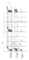
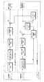
図1は、多階層構造を用いたスケーラブルビデオコーデックを示す図面である。まず、基礎階層をQCIF(Quarter Common Intermediate Format)、15Hz(フレームレート)に定義し、第1向上階層をCIF(Common Intermediate Format)、30hzに、第2向上階層をSD(Standard Definition)、60hzに定義する。もし、CIF 0.5 Mbpsストリームを所望するならば、第1向上階層のCIF_30Hz_0.7Mでビット率が0.5Mになるようにビットストリームを切って送ればよい。このような方式で、空間的、時間的、SNRスケーラビリティーを具現しうる。 FIG. 1 is a diagram illustrating a scalable video codec using a multi-layer structure. First, the basic layer is defined as QCIF (Quarter Common Intermediate Format) and 15 Hz (frame rate), the first enhancement layer is defined as CIF (Common Intermediate Format), 30 hz, and the second enhancement layer is defined as SD (Standard Definition), 60 hz. Define. If a CIF 0.5 Mbps stream is desired, the bit stream may be cut and sent so that the bit rate is 0.5 M at CIF_30 Hz_0.7 M of the first enhancement layer. In this manner, spatial, temporal, and SNR scalability can be implemented.
図1に示されたように、同じ時間的位置を有する各階層でのフレーム(例えば、10、20、及び30)は、そのイメージが類似していると推定しうる。したがって、下位階層のテクスチャーから(直接またはアップサンプリングした後)現在階層のテクスチャーを予測し、予測された値と実際現在階層のテクスチャーとの差をエンコーディングする方法が知られている。“Scalable Video Model 3.0 of ISO/IEC 21000−13 Scalable Video Coding”(以下“SVM 3.0”と称する)では、このような方法をイントラBL予測(Intra_BL prediction)と定義している。 As shown in FIG. 1, frames at each level (eg, 10, 20, and 30) that have the same temporal position may be presumed that their images are similar. Therefore, a method is known in which the texture of the current layer is predicted from the texture of the lower layer (directly or after upsampling), and the difference between the predicted value and the texture of the actual current layer is encoded. In “Scalable Video Model 3.0 of ISO / IEC 21000-13 Scalable Video Coding” (hereinafter referred to as “SVM 3.0”), such a method is defined as intra BL prediction (Intra_BL prediction).
このように、SVM 3.0では、既存のH.264で現在フレームを構成するブロックないしマクロブロックに対する予測のために使われたインター予測及び方向的イントラ予測(directional intra prediction)以外にも、現在ブロックとこれに対応する下位階層ブロックとの連関性を用いて現在ブロックを予測する方法を追加的に採択している。このような予測方法を、“イントラBL(Intra_BL)予測”と称し、このような予測を使用して符号化するモードを“イントラBLモード”と称する。 Thus, in SVM 3.0, existing H.264 In addition to the inter prediction and directional intra prediction used for prediction of the block or macroblock constituting the current frame in H.264, the relationship between the current block and the corresponding lower layer block The method of predicting the current block is additionally adopted. Such a prediction method is referred to as “intra BL (Intra_BL) prediction”, and a mode in which encoding is performed using such prediction is referred to as “intra BL mode”.
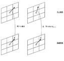
図2は、前記3種の予測方法を説明する概略図であって、現在フレーム11のあるマクロブロック14に対してイントラ予測を行う場合(1)と、現在フレーム11と他の時間的位置にあるフレーム12とを用いてインター予測を行う場合(2)と、前記マクロブロック14と対応する基礎階層フレーム13の領域16に対するテクスチャーデータを用いてイントラBL予測を行う場合(3)と、を各々示している。
FIG. 2 is a schematic diagram for explaining the three kinds of prediction methods. In the case where intra prediction is performed on a
このように、前記スケーラブルビデオコーディング標準ではマクロブロック単位で前記3つの予測方法のうち、有利な1つの方法を選択して利用する。 As described above, in the scalable video coding standard, an advantageous one of the three prediction methods is selected and used for each macroblock.
ところが、このような予測方法を使用するためには、如何なる予測方法が使用されたか、または予測時に参照するデータが何かについての情報をデコーディング側に送るために多様なフラッグを使用する。マクロブロック単位、またはスライス、フレーム単位でエンコーディングする場合、該当単位によって小さくは1bitから数bitまたは数十bitに該当しうる。このような情報が全体動画像にマクロブロックごとに、またはスライスやフレームごとに設定される場合にデータは大きくなる。したがって、これらの情報を効率的に圧縮するための方法及び装置が必要である。 However, in order to use such a prediction method, various flags are used to send information about what prediction method is used or what data is referred to at the time of prediction to the decoding side. When encoding is performed in units of macroblocks, slices, or frames, the encoding can be as small as 1 bit to several bits or tens of bits depending on the corresponding unit. Data becomes large when such information is set for each macroblock or for each slice or frame in the entire moving image. Therefore, there is a need for a method and apparatus for efficiently compressing this information.
本発明は、前記問題点を改善するために案出されたものであって、本発明は、基礎階層のデータを通じて予測方法に所要されるデータの大きさを減らすところにその目的がある。 The present invention has been devised in order to improve the above-mentioned problems, and the present invention has an object to reduce the size of data required for the prediction method through the data of the base layer.
本発明の目的は、以上で言及した目的に制限されず、言及されていない他の目的は下の記載から当業者に明確に理解されうる。 The objects of the present invention are not limited to the objects mentioned above, and other objects not mentioned can be clearly understood by those skilled in the art from the following description.
本発明の一実施形態によるビデオ信号の残差予測フラッグをコーディングする方法は、多階層ビデオ信号の向上階層を構成するブロックの残差データを、対応する下位階層ブロックの残差データから予測してコーディングするために、前記予測如何を示す残差予測フラッグをコーディングする方法において、前記下位階層の対応するブロックの残差データのエネルギーを計算するステップ、前記エネルギーによって前記残差予測フラッグのコーディング方法を決定するステップ、及び前記決定されたコーディング方法によって残差予測フラッグをコーディングするステップを含む。 A method for coding a residual prediction flag of a video signal according to an embodiment of the present invention predicts residual data of a block constituting an enhancement layer of a multi-layer video signal from residual data of a corresponding lower layer block. A method of coding a residual prediction flag indicating whether or not to predict for coding, calculating energy of residual data of a corresponding block of the lower layer, coding method of the residual prediction flag according to the energy Determining, and coding a residual prediction flag according to the determined coding method.
本発明の他の実施形態によるビデオ信号の残差予測フラッグをコーディングする方法は、多階層ビデオ信号の向上階層を構成するブロックの残差データを対応する下位階層ブロックの残差データから予測してコーディングするために、前記予測如何を示す残差予測フラッグをコーディングする方法において、前記下位階層の対応するブロックに対する符号化ブロックパターンの値を計算するステップと、前記計算した符号化ブロックパターンの値によって前記残差予測フラッグのコーディング方法を決定するステップと、前記決定されたコーディング方法によって残差予測フラッグをコーディングするステップと、を含む。 A method for coding a residual prediction flag of a video signal according to another embodiment of the present invention predicts residual data of a block constituting an enhancement layer of a multi-layer video signal from residual data of a corresponding lower layer block. In the method of coding a residual prediction flag indicating whether or not to predict, a coding block pattern value for a corresponding block of the lower layer is calculated, and the calculated coding block pattern value is coded. Determining a coding method of the residual prediction flag, and coding a residual prediction flag according to the determined coding method.
本発明の一実施形態によるビデオ信号の残差予測フラッグをデコーディングする方法は、多階層ビデオ信号の向上階層を構成するブロックの残差データを、対応する下位階層ブロックの残差データから予測してデコーディングするために、前記予測如何を示す残差予測フラッグをデコーディングする方法において、前記下位階層の対応するブロックの残差データのエネルギーを計算するステップと、前記エネルギーによって前記残差予測フラッグのデコーディング方法を決定するステップと、前記決定されたデコーディング方法によって残差予測フラッグをデコーディングするステップと、を含む。 A method of decoding a residual prediction flag of a video signal according to an embodiment of the present invention predicts residual data of a block constituting an enhancement layer of a multi-layer video signal from residual data of a corresponding lower layer block. In the method of decoding a residual prediction flag indicating whether or not to predict, the energy of residual data of a corresponding block of the lower layer is calculated, and the residual prediction flag is calculated according to the energy. Determining a decoding method, and decoding a residual prediction flag according to the determined decoding method.
本発明の他の実施形態によるビデオ信号の残差予測フラッグをデコーディングする方法は、多階層ビデオ信号の向上階層を構成するブロックの残差データを対応する下位階層ブロックの残差データから予測してデコーディングするために、前記予測如何を示す残差予測フラッグをデコーディングする方法において、前記下位階層の対応するブロックに対する符号化ブロックパターンの値を計算するステップと、前記計算した符号化ブロックパターンの値によって前記残差予測フラッグのデコーディング方法を決定するステップと、前記決定されたコーディング方法によって残差予測フラッグをデコーディングするステップと、を含む。 A method of decoding a residual prediction flag of a video signal according to another embodiment of the present invention predicts residual data of a block constituting an enhancement layer of a multi-layer video signal from residual data of a corresponding lower layer block. In the method of decoding the residual prediction flag indicating whether or not to predict, a value of an encoded block pattern for a corresponding block in the lower layer is calculated, and the calculated encoded block pattern is decoded. Determining a decoding method of the residual prediction flag according to the value of, and decoding a residual prediction flag according to the determined coding method.
本発明のさらに他の実施形態によるビデオ信号の残差予測フラッグをデコーディングする方法は、多階層ビデオ信号の向上階層を構成するブロックの残差データを対応する下位階層ブロックの残差データから予測してデコーディングするために、前記予測如何を示す残差予測フラッグをデコーディングする方法において、前記下位階層の対応するブロックに対する符号化ブロックパターンの値を確認するステップと、前記符号化ブロックパターンを構成するそれぞれのビットに1の値を有するビットの存否を判断するステップと、前記判断の結果、1の値を有するビットが1つ以上存在する否かかによって前記残差予測フラッグのデコーディング方法を決定するステップと、前記決定されたデコーディング方法によって残差予測フラッグをデコーディングするステップと、を含む。 According to another embodiment of the present invention, a method for decoding a residual prediction flag of a video signal predicts residual data of a block constituting an enhancement layer of a multi-layer video signal from residual data of a corresponding lower layer block. In the method of decoding the residual prediction flag indicating whether or not to predict, a method of checking a value of an encoded block pattern for a corresponding block in the lower layer, and decoding the encoded block pattern, Decoding method of the residual prediction flag according to the step of determining whether or not there is a bit having a value of 1 in each of the constituent bits and whether or not one or more bits having a value of 1 exist as a result of the determination And determining a residual prediction flag according to the determined decoding method. Comprising the steps of over loading, the.
本発明の他の実施形態によるデコーディング方法は、多階層ビデオ信号の復号化しようとする向上階層をデコーディングする方法において、前記向上階層に対応する下位階層の符号化ブロックパターン値から、前記向上階層の前記下位階層からの予測如何を示す残差予測フラッグのデコーディング方法を決定するステップと、前記デコーディング方法によって選択されたエントロピー復号化方法によって前記残差予測フラッグを復号化し、前記残差予測フラッグによって前記向上計測を復号化する復号化ステップと、を含む。 According to another embodiment of the present invention, there is provided a decoding method for decoding an enhancement layer to be decoded from a multi-layer video signal, wherein the enhancement layer is obtained from an encoded block pattern value of a lower layer corresponding to the enhancement layer. Determining a decoding method of a residual prediction flag indicating whether or not to predict from the lower layer of a layer; decoding the residual prediction flag by an entropy decoding method selected by the decoding method; and Decoding the enhancement measure with a prediction flag.
本発明の他の実施形態によるデコーディング装置は、多階層ビデオ信号の向上階層を構成するブロックの残差データを対応する下位階層ブロックの残差データから予測してデコーディングするために、前記予測如何を示す残差予測フラッグをデコーディングする装置において、前記下位階層ブロックに対する符号化ブロックパターンの値を解釈するパージング部と、前記符号化ブロックパターン値によって前記残差予測フラッグに対するデコーディング方法を決定し、前記デコーディング方法によって前記残差予測フラッグをデコーディングするデコーディング部と、を備える。 A decoding apparatus according to another embodiment of the present invention predicts and decodes residual data of blocks constituting an enhancement layer of a multi-layer video signal by predicting from residual data of corresponding lower layer blocks. In an apparatus for decoding a residual prediction flag indicating how, a parsing unit that interprets a value of an encoded block pattern for the lower layer block, and a decoding method for the residual prediction flag are determined by the encoded block pattern value And a decoding unit for decoding the residual prediction flag by the decoding method.
本発明のさらに他の実施形態によるデコーディング装置は、多階層ビデオ信号の復号化しようとする向上階層をデコーディングする装置において、前記向上階層に対応する下位階層の符号化ブロックパターン値を解釈するパージング部と、前記符号化ブロックパターン値から前記向上階層の前記下位階層からの予測如何を示す残差予測フラッグのデコーディング方法を決定し、前記デコーディング方法によって前記残差予測フラッグを逆エントロピー復号化し、前記向上階層を逆エントロピー復号化する逆エントロピー復号化部と、前記向上階層を逆量子化する逆量子化部と、前記逆量子化された向上階層を逆時間的変換し、前記残差予測フラッグによって前記下位階層から予測して復号化する逆時間的変換部と、を備えることを特徴とする。 A decoding apparatus according to another exemplary embodiment of the present invention interprets an encoding block pattern value of a lower layer corresponding to the enhancement layer in an apparatus for decoding the enhancement layer to be decoded of a multi-layer video signal. A decoding unit that determines a decoding method of a residual prediction flag indicating whether or not to predict from the lower layer of the enhancement layer based on the encoded block pattern value, and performs reverse entropy decoding on the residual prediction flag by the decoding method An inverse entropy decoding unit that performs inverse entropy decoding of the enhancement layer, an inverse quantization unit that inversely quantizes the enhancement layer, an inverse temporal transform of the inversely quantized enhancement layer, and the residual An inverse temporal conversion unit that predicts and decodes from the lower layer by a prediction flag.
その他の実施例の具体的な事項は詳細な説明及び図面に含まれている。 Specific details of other embodiments are included in the detailed description and drawings.
本発明を具現することによって、基礎階層のデータで向上階層のデータが基礎階層のデータを参照しているか否かを判断して、データの圧縮率を高めることができる。 By embodying the present invention, it is possible to determine whether or not the data of the enhancement layer refers to the data of the base layer by using the data of the base layer, and the data compression rate can be increased.
本発明の利点及び特徴、そしてこれを達成する方法は添付された図面に基づいて詳細に後述されている実施例を参照すれば明確になる。しかし、本発明は以下で開示される実施例に限定されるものではなく、この実施例から外れて多様な形に具現でき、本明細書で説明する実施例は本発明の開示を完全にし、本発明が属する技術分野で当業者に発明の範ちゅうを完全に報せるために提供されるものであり、本発明は請求項及び発明の詳細な説明により定義されるだけである。一方、明細書全体に亙って同一な参照符号は同一な構成要素を示す。 Advantages and features of the present invention and methods of achieving the same will be apparent with reference to the embodiments described below in detail with reference to the accompanying drawings. However, the present invention is not limited to the embodiments disclosed below, and can be embodied in various forms that deviate from the embodiments, and the embodiments described herein complete the disclosure of the present invention. The present invention is provided in order to fully inform those skilled in the art in the technical field to which the present invention pertains, and the present invention is only defined by the claims and the detailed description of the invention. On the other hand, the same reference numerals denote the same components throughout the specification.
以下、本発明の実施形態によって、基礎階層と向上階層のデータにより予測情報をデコーディングしてコーディング率を向上させる装置及び方法を説明するためのブロック図またはフローチャートに関する図面を参考して本発明について説明する。この時、フローチャートの各ブロックとフロ−チャートの組合わせはコンピュータプログラムインストラクションにより実行可能なのが理解できるであろう。これらコンピュータプログラムインストラクションは、汎用コンピュータ、特殊用コンピュータまたはその他のプログラマブルデータプロセッシング装備のプロセッサーに搭載されうるので、コンピュータまたはその他のプログラマブルデータプロセッシング装備のプロセッサーを通じて実行されるそのインストラクションがフローチャートのブロックで説明された機能を行う手段を生成するように機構を作れる。これらコンピュータプログラムインストラクションは特定方式で機能を具現するためにコンピュータまたはその他のプログラマブルデータプロセッシング装備を指向できるコンピュータ利用可能またはコンピュータ判読可能メモリに保存されることも可能なので、そのコンピュータ利用可能またはコンピュータ判読可能メモリに保存されたインストラクションはフローチャートのブロックで説明された機能を行うインストラクション手段を内包する製造品目を生産することも可能である。コンピュータプログラムインストラクションはコンピュータまたはその他のプログラム可能なデータプロセッシング装備上に搭載することも可能なので、コンピュータまたはその他のプログラマブルデータプロセッシング装備上で一連の動作段階が実行されてコンピュータで実行されるプロセスを生成し、コンピュータまたはその他のプログラマブルデータプロセッシング装備を行うインストラクションはフローチャートのブロックで説明された機能を実行するための段階を提供することも可能である。 Hereinafter, according to an embodiment of the present invention, the present invention will be described with reference to a block diagram or a flowchart related to a flowchart for explaining an apparatus and method for improving prediction rate by decoding prediction information from data of a base layer and an enhancement layer. explain. At this time, it will be understood that the combination of each block of the flowchart and the flowchart can be executed by a computer program instruction. These computer program instructions may be installed in a general purpose computer, special purpose computer or other programmable data processing equipped processor, so that instructions executed through the computer or other programmable data processing equipped processor are illustrated in the flowchart blocks. You can create a mechanism to create a means to perform a specific function. These computer program instructions can also be stored in a computer-usable or computer-readable memory that can be directed to a computer or other programmable data processing equipment to implement the function in a particular manner, so that the computer-usable or computer-readable The instructions stored in the memory can also produce manufactured items that contain instruction means for performing the functions described in the flowchart blocks. Computer program instructions can also be implemented on a computer or other programmable data processing equipment, so that a series of operational steps are performed on the computer or other programmable data processing equipment to create a computer-executed process. Instructions that implement a computer or other programmable data processing equipment may also provide steps for performing the functions described in the flowchart blocks.
また、各ブロックは特定の論理的機能を行うための一つ以上の実行可能なインストラクションを含むモジュール、セグメントまたはコードの一部を示すことができる。また、いくつの代替実行例では、ブロックで言及された機能が順序を外れて発生することも可能であるということに注目せねばならない。例えば、連続して図示されている2つのブロックは、実質的に同時に行われてもよく、またはそのブロックが時々該当する機能によって逆順に行われてもよい。 Each block may also represent a module, segment, or portion of code that includes one or more executable instructions for performing a particular logical function. It should also be noted that in some alternative implementations, the functions mentioned in the block can occur out of order. For example, two blocks shown in succession may be performed substantially simultaneously, or the blocks may be performed in reverse order depending on the function to which they are sometimes applicable.
図2で説明した予測方法をデコーディング側で使用するために如何なる方式の予測がなされたか、あるいは如何なるデータを参照しているかなどについての情報を設定してエンコーディング側から伝送する。データを圧縮する技法のうち1つであるエントロピーコーディングは、無損失圧縮を使用して最終圧縮を行う。通常ハフマンコーディング(Huffma ncoding)を多用する。ハフマンコーディングは可変長(variable length)コーディング方式であって、情報が現れる確率によってビットを割り当てる方式である。したがって、エントロピーコーディングを使用して全体ビット効率を高めるためには、情報を示す方式を調節する。 In order to use the prediction method described in FIG. 2 on the decoding side, information on what type of prediction is made or what data is being referenced is set and transmitted from the encoding side. One technique for compressing data, entropy coding, uses lossless compression to perform final compression. Usually, Huffman coding is frequently used. Huffman coding is a variable length coding scheme in which bits are assigned according to the probability that information will appear. Therefore, in order to increase the overall bit efficiency using entropy coding, the method of indicating information is adjusted.
一方、図2で説明した予測方法をデコーディング側に知らせるための情報のうち、基礎階層の情報を参照して予測する方式が存在する。例えば、基礎階層の残差データを参照して予測するか、基礎階層のモーションベクトルを参照して予測する場合が発生する。この際、基礎階層の情報を参照して予測方法を適用しているかを知らせるためのフラッグとして、残差予測フラッグresidual_prediction_flag、モーション予測フラッグ(motion_prediction_flag)などの予測情報が存在する。これらフラッグは、マクロブロックまたはスライスやフレーム単位で設定しうる。したがって、これらフラッグは、前記単位別に常に存在する情報であるために、これらの大きさを減らすか、エントロピーコーディングのようにコーディング時に圧縮効率を高めることが重要である。このために前記予測フラッグをデコーディング端で予測可能に情報を設定し、前記情報を用いて前記予測フラッグを復元しうる。 On the other hand, among the information for informing the decoding side of the prediction method described with reference to FIG. For example, the prediction may be performed with reference to the residual data of the base layer or the prediction with reference to the motion vector of the base layer. At this time, prediction information such as a residual prediction flag residual_prediction_flag and a motion prediction flag (motion_prediction_flag) exists as a flag for notifying whether the prediction method is applied with reference to the information of the base layer. These flags can be set in units of macroblocks or slices or frames. Therefore, since these flags are information that always exists for each unit, it is important to reduce the size of these flags or to increase the compression efficiency at the time of coding like entropy coding. For this purpose, information can be set so that the prediction flag can be predicted at the decoding end, and the prediction flag can be restored using the information.
図3は、ビデオコーディングでの残差予測の例を示す。残差予測とは、残差結果、すなわち、図2で説明した予測方法のうち、1つを使用して得た結果である残差データについてもう一度予測を行うことを意味する。基礎階層のいずれか1つのマクロブロック、スライスまたはフレーム14は、図2で説明した予測方法のうち、1つである時間的インター予測を使用して残差データとして、マクロブロック、スライスまたはフレームを構成しうる。この際、基礎階層を参照する向上階層のマクロブロック、スライス、またはフレームも基礎階層の残差データを参照する残差予測を行える。以下、マクロブロックを中心に説明するが、本発明の範囲がマクロブロックに限定されるものではない。マクロブロック以外に、スライス、フレームにも適用しうる。
FIG. 3 shows an example of residual prediction in video coding. Residual prediction means that a residual result, that is, residual data that is a result obtained by using one of the prediction methods described in FIG. 2 is predicted once again. Any one macroblock, slice, or
向上階層のマクロブロックが時間的インター予測を行うために基礎階層の残差を参照しうる。デコーディング端に基礎階層の残差を参照したことを知らせるために、残差予測フラッグresidual_prediction_flagを1に設定しうる。ところが、基礎階層のマクロブロック(残差データで構成されたマクロブロック)がいずれも0である値を有するか、0でない情報を有するピクセルが特定基準(threshold、閾値)より低い場合、またはcbp値が0であるか、特定基準より低い値を有する場合には、残差予測フラッグを設定する必要がない。基礎階層で実行した時間的インター予測の結果、動きがほとんどない場合を意味する。したがって、この場合、向上階層のマクロブロックは、参照するデータがないか、あるいは不足するので、残差予測フラッグが必要でない。したがって、このような場合には、残差予測フラッグを設定しないことによってビットを節約しうる。 An enhancement layer macroblock may refer to a base layer residual to perform temporal inter prediction. The residual prediction flag residual_prediction_flag may be set to 1 to inform the decoding end that the residual of the base layer has been referred to. However, if all the macroblocks of the base layer (macroblocks composed of residual data) have a value of 0, or pixels having non-zero information are lower than a specific criterion (threshold, threshold), or the cbp value Is 0 or has a value lower than a specific criterion, it is not necessary to set a residual prediction flag. It means that there is almost no movement as a result of temporal inter prediction performed in the base layer. Therefore, in this case, the macro block in the enhancement layer does not need the residual prediction flag because there is no data to be referred to or is insufficient. Therefore, in such a case, bits can be saved by not setting the residual prediction flag.
残差予測は、向上階層のモーションベクトルと基礎階層のモーションベクトルとが類似した場合に意味がある。したがって、各階層間のモーションベクトルの差は、残差予測フラッグの値を予測する因子になりうる。まず、残差予測フラッグの値を予測するための決定情報を便宜上予測決定フラッグという。JSVM(Joint Scalable Video Model)1で残差予測フラッグresidual_prediction_flagを設定する代わりに、残差予測フラッグと予測決定フラッグPrdRpFlagとの差をコーディングする場合に、エントロピーコーディングの効率を高めうる。したがって、このような差を示す残差予測差フラッグresidual_prediction_flag_diffを導入してビデオ情報をエンコーディングしうる。 The residual prediction is meaningful when the motion vector of the enhancement layer is similar to the motion vector of the base layer. Therefore, the motion vector difference between the layers can be a factor for predicting the value of the residual prediction flag. First, the determination information for predicting the value of the residual prediction flag is referred to as a prediction determination flag for convenience. Instead of setting the residual prediction flag residual_prediction_flag in JSVM (Joint Scalable Video Model) 1, the efficiency of entropy coding can be improved when coding the difference between the residual prediction flag and the prediction determination flag PrdRpFlag. Therefore, video information can be encoded by introducing a residual prediction difference flag residual_prediction_flag_diff indicating such a difference.
残差予測差フラッグを求める方法は、次の通りである。まず、基礎階層の残差に存在する非ゼロピクセル(non−zero pixel)の数が一定基準(threshold)以下である場合には残差予測フラッグをコーディングする過程を経る。 The method for obtaining the residual prediction difference flag is as follows. First, when the number of non-zero pixels existing in the residual of the base layer is equal to or less than a certain threshold (threshold), a process of coding a residual prediction flag is performed.
非ゼロピクセルの数が一定基準以上である場合には、残差予測フラッグではない残差予測差フラッグをコーディングする。残差予測差フラッグを求めるためには、基礎階層のモーションベクトルBaseMVと向上階層のモーションベクトルCurrMVとの差を使用する。残差予測差フラッグをコーディングするためには、予測決定フラッグPrpRpFlagを求めなければならない。 If the number of non-zero pixels is greater than or equal to a certain criterion, a residual prediction difference flag that is not a residual prediction flag is coded. In order to obtain the residual prediction difference flag, the difference between the motion vector BaseMV of the base layer and the motion vector CurrMV of the enhancement layer is used. In order to code the residual prediction difference flag, the prediction decision flag PrpRpFlag must be determined.
もし、|BaseMV−CurrMV|<特定値(threshold)である場合、PrpRpFlagを1とし、その他の場合は0にする。求められたPrpRpFlagと残差予測フラッグresidual_predicion_flagとの差になる値である残差予測差フラッグresidual_prediction_flag_diffをコーディングする。前記の過程を再び説明すれば次の通りである。 If | BaseMV-CurrMV | <specific value (threshold), PrpRpFlag is set to 1; otherwise, it is set to 0. The residual prediction difference flag residual_prediction_flag_diff, which is a difference between the obtained PrpRpFlag and the residual prediction flag residual_prediction_flag, is coded. The above process will be described again as follows.
基礎階層の残差のエネルギー(または非ゼロピクセルの数)が特定値Thresholdresidualより低い場合、残差予測フラッグresidual_predicion_flagをコーディングしない。 If the base layer residual energy (or the number of non-zero pixels) is lower than a specific value Threshold residual , the residual prediction flag residual_prediction_flag is not coded.
その他の場合を再び2つに分ければ次の通りである。|BaseMV−CurrMV|<特定値ThresholdMVである場合には、1−residual_prediction_flagをコーディングし、そうでない場合には、0−residual_prediction_flag、すなわちresidual_prediction_flagをコーディングする。 The other cases are again divided into two as follows. | BaseMV-CurrMV | <specific value Threshold MV , 1-residual_prediction_flag is coded, otherwise 0-residual_prediction_flag, ie, residual_prediction_flag is coded.
前記の概念を具現するためのフローチャートを説明すれば図4のようである。 A flow chart for implementing the above concept is shown in FIG.
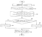
図4は、本発明の一実施形態による残差予測フラッグのエンコーディング効率を高めるフローチャートである。まず、基礎階層の残差データを求める(S101)。基礎階層の残差データは、基礎階層が時間的インターコーディングのように他のフレームまたは他のブロックなどを参照して得た結果を意味する。基礎階層の残差データが特定値Thresholdresidualより小さい場合(S105)、例えば、0を基準にした場合、または全体エネルギーが特定値より小さい場合には、残差予測フラッグresidual_prediction_flagを設定する必要がない。したがって、残差予測フラッグをコーディングしない。 FIG. 4 is a flowchart for increasing the encoding efficiency of a residual prediction flag according to an embodiment of the present invention. First, basic layer residual data is obtained (S101). The residual data of the base layer means a result obtained by referring to other frames or other blocks by the base layer as in temporal intercoding. When the residual data of the base layer is smaller than the specific value Threshold residual (S105), for example, when 0 is used as a reference, or when the total energy is smaller than the specific value, there is no need to set the residual prediction flag residual_prediction_flag. . Therefore, the residual prediction flag is not coded.
一方、基礎階層の残差データが特定値Thresholdresidualより大きい場合(S105)、残差予測フラッグresidual_prediction_flagを選択的に1または0を有しうる。選択のために予測決定フラッグを設定する基準を定めることができる。S110ステップで、基礎階層のモーションベクトルBaseMVと向上階層または現在階層のモーションベクトルCurrMVとの差が特定値ThresholdMVより小さい場合、基礎階層の残差データを使用する可能性が高い。したがって予測決定フラッグを1にする(S111)。一方、S110ステップで、基礎階層のモーションベクトルBaseMVと向上階層または現在階層のモーションベクトルCurrMVとの差が特定値ThresholdMVより大きい場合、基礎階層の残差データを使用する可能性が低い。したがって、予測決定フラッグを0にする(S112)。S111及びS112ステップで設定した予測決定フラッグ及び予測決定フラッグと残差予測フラッグresidual_prediction_flagの差である残差予測差フラッグをコーディングする。エンコーディング端ではマクロブロック別に、またはスライス単位またはフレーム単位で前記の予測決定フラッグと残差予測差フラッグとをコーディングしうる。 On the other hand, if the residual data of the base layer is larger than the specific value Threshold residual (S105), the residual prediction flag residual_prediction_flag may selectively have 1 or 0. A criterion for setting a prediction decision flag for selection can be defined. In step S110, if the difference between the motion vector BaseMV of the base layer and the motion vector CurrMV of the enhancement layer or the current layer is smaller than the specific value Threshold MV , there is a high possibility that the residual data of the base layer is used. Therefore, the prediction determination flag is set to 1 (S111). On the other hand, if the difference between the motion vector BaseMV of the base layer and the motion vector CurrMV of the enhancement layer or the current layer is larger than the specific value Threshold MV in step S110, the possibility of using the residual data of the base layer is low. Therefore, the prediction determination flag is set to 0 (S112). The prediction determination flag set in steps S111 and S112 and the residual prediction difference flag which is the difference between the prediction determination flag and the residual prediction flag residual_prediction_flag are coded. At the encoding end, the prediction determination flag and the residual prediction difference flag may be coded for each macroblock, for each slice or for each frame.
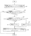
図5は、本発明の一実施形態による図4でエンコーディングされたデータをデコーディングするフローチャートである。まず、エンコーディングされたデータで基礎階層の残差データを求める(S151)。残差データが特定値Thresholdresidualより小さい場合(S155)、エンコーディングされた予測決定フラッグと残差予測差フラッグとの差を通じて残差予測フラッグresidual_prediction_flagを設定する(S161)。エンコーディング側で予測決定フラッグをPrdRpFlag、残差予測差フラッグをresidual_pred_flag_diffとおく場合、residual_pred_flag_diff=PrdRpFlag−residual_prediction_flagと求められる。したがって、residual_prediction_flagを求めるためには、PrdRpFlagとresidual_pred_flag_diffとの差を求めるならば得られる。 FIG. 5 is a flowchart for decoding the data encoded in FIG. 4 according to an embodiment of the present invention. First, the base layer residual data is obtained from the encoded data (S151). If the residual data is smaller than the specific value Threshold residual (S155), the residual prediction flag residual_prediction_flag is set through the difference between the encoded prediction determination flag and the residual prediction difference flag (S161). When the encoding side sets the prediction determination flag as PrdRpFlag and the residual prediction difference flag as residual_pred_flag_diff, it is obtained as residual_pred_flag_diff = PrdRpFlag-residual_prediction_flag. Therefore, in order to obtain the residual_prediction_flag, it can be obtained by obtaining the difference between PrdRpFlag and residual_pred_flag_diff.
残差データが特定値Thresholdresidualより大きい場合(S155)、残差予測フラッグresidual_prediction_flagを参照して向上階層を生成したものではないので、残差予測フラッグを0に設定する(S162)。 When the residual data is larger than the specific value Threshold residual (S155), the residual prediction flag is set to 0 (S162) because the improvement hierarchy is not generated with reference to the residual prediction flag residual_prediction_flag.
前述した過程は、基礎階層の残差データを参照しているか否かと関連した残差予測フラッグの代りに、他の情報をエンコーディングしてエンコーディング効率を向上させる場合について説明した。以下、これと類似した方式で、基礎階層のモーション情報を参照するモーション予測フラッグの代りに、他の情報をエンコーディングしてエンコーディング効率を向上させる場合について説明する。 The above-described process has been described for the case where the encoding efficiency is improved by encoding other information instead of the residual prediction flag related to whether or not the residual data of the base layer is referenced. Hereinafter, a case in which encoding efficiency is improved by encoding other information instead of the motion prediction flag that refers to the motion information of the base layer in a similar manner will be described.
図6は、ビデオコーディングでのモーション予測の例を示す。モーション予測とは、基礎階層のモーションベクトルを参照して向上階層または現在階層のモーションベクトルを予測することを意味する。したがって、モーション予測フラッグmotion_prediction_flagが1である場合、基礎階層のモーションベクトルを参照して向上階層のモーションベクトルを予測する。逆に、0である場合、基礎階層のモーションベクトルを参照しない。図6の21及び25は、マクロブロックまたはサブブロック、スライス、フレームのうち、いずれか1つである。説明の便宜上、マクロブロックを中心に説明する。基礎階層のマクロブロック21のモーションベクトルと向上階層のマクロブロック25のモーションベクトルとを比較すれば、相互同一である。この場合、モーション予測フラッグmotion_prediction_flagをコーディングする必要がないので、このステップをスキップする。ここで、両モーションベクトルが同じか否かより一定基準(ThresholdMotion)以下である場合には、モーション予測フラッグをコーディングしない方式を採用しうる。
FIG. 6 shows an example of motion prediction in video coding. Motion prediction refers to predicting a motion vector in the enhancement layer or the current layer with reference to a motion vector in the base layer. Therefore, when the motion prediction flag motion_prediction_flag is 1, the motion vector in the enhancement layer is predicted with reference to the motion vector in the base layer. Conversely, when it is 0, the motion vector of the base layer is not referred to.
一方、基礎階層のモーションベクトルと空間的に隣接した領域を通じて求められたモーションベクトルを比較してモーション予測フラッグmotion_prediction_flagを判断しうる。空間的に隣接する領域から算出されたモーションベクトルは正確なモーションベクトルを提供する。しかし、モーション予測が常に正確に行われるものではない。その結果、モーションベクトルにおける大きな差をもたらせる。基礎階層のモーションベクトルを通じた予測が、空間的モーション予測より正確性が劣る場合でも、全般的に合理的な結果を提供する。このような観点で、モーション予測フラッグmotion_prediction_flagの予測に、前記両モーションベクトルの差を使用しうる。 Meanwhile, the motion prediction flag motion_prediction_flag may be determined by comparing a motion vector obtained through a spatially adjacent region with a motion vector in the base layer. Motion vectors calculated from spatially adjacent regions provide accurate motion vectors. However, motion prediction is not always performed accurately. As a result, large differences in motion vectors can be brought about. Predictions through base layer motion vectors provide generally reasonable results even when they are less accurate than spatial motion predictions. From this point of view, the difference between the two motion vectors can be used to predict the motion prediction flag motion_prediction_flag.
マクロブロック22とマクロブロック26とのモーションベクトルの差が特定値ThresholdMV以上である場合には、モーション予測フラッグmotion_prediction_flagを1に設定する可能性が高いので、予測決定フラッグPrdMotPrdFlagを1にする。一方、マクロブロック22とマクロブロック26とのモーションベクトルの差が特定値ThresholdMV以下である場合には、モーション予測フラッグmotion_prediction_flagを0に設定する可能性が高いので、予測決定フラッグPrdMotPrdFlagを0にする。
If the difference between the motion vectors of the
前記過程を経て予測決定フラッグの値を定めれば、この値とモーション予測フラッグmotion_prediction_flagとの差を求めてエンコーディングする。差は、モーション予測差フラッグmotion_pred_flag_diffに設定してエンコーディングしうる。 If the value of the prediction determination flag is determined through the above process, the difference between this value and the motion prediction flag motion_prediction_flag is obtained and encoded. The difference may be encoded by setting the motion prediction difference flag motion_pred_flag_diff.
図7は、本発明の一実施形態によるモーション予測フラッグのエンコーディング効率を高めるフローチャートである。まず、基礎階層で予測したモーションベクトルPredict_MV_From_BaseLayerと空間的に隣接した領域で予測したモーションベクトルPredict_MV_From_Spatiaを求める(S201)。そして、両モーションベクトル間の差が特定値ThresholdMotionより小さい場合には、モーション予測フラッグをエンコーディングしない(S205)。一方、両モーションベクトル間の差が特定値ThresholdMotionより大きい場合には、モーション予測フラッグの代りに、モーション予測フラッグを予測するための予測決定フラッグを設定する過程に進む。基礎階層で予測したモーションベクトルPredict_MV_From_BaseLayerと空間的に隣接したモーションベクトルPredict_MV_From_Spatiaとの差が特定値ThresholdMVより大きい場合、または小さい場合によって予測決定フラッグを設定する値が変わる(S210)。 FIG. 7 is a flowchart for increasing the encoding efficiency of a motion prediction flag according to an embodiment of the present invention. First, a motion vector Predict_MV_From_Spatia predicted in an area spatially adjacent to the motion vector Predict_MV_From_BaseLayer predicted in the base layer is obtained (S201). If the difference between the two motion vectors is smaller than the specific value Threshold Motion , the motion prediction flag is not encoded (S205). On the other hand, when the difference between the two motion vectors is larger than the specific value Threshold Motion, the process proceeds to a process of setting a prediction determination flag for predicting the motion prediction flag instead of the motion prediction flag. The value for setting the prediction determination flag changes depending on whether the difference between the motion vector Predict_MV_From_BaseLayer predicted in the base layer and the spatially adjacent motion vector Predict_MV_From_Spatia is larger or smaller than the specific value Threshold MV (S210).
S210において、差が特定値ThresholdMVより大きい場合には、予測決定フラッグを1に設定し(S211)、S210において、差が特定値ThresholdMVより小さい場合には、予測決定フラッグを0に設定する(S212)。S211及びS212ステップで設定した予測決定フラッグの値とモーション予測フラッグmotion_prediction_flagとの差であるモーション予測差フラッグと予測決定フラッグをエンコーディングする(S220)。 If the difference is larger than the specific value Threshold MV in S210, the prediction determination flag is set to 1 (S211). If the difference is smaller than the specific value Threshold MV in S210, the prediction determination flag is set to 0. (S212). The motion prediction difference flag and the prediction determination flag, which are the difference between the value of the prediction determination flag set in steps S211 and S212 and the motion prediction flag motion_prediction_flag, are encoded (S220).
図8は、本発明の一実施形態による図7でエンコーディングされたデータをデコーディングするフローチャートである。まず、エンコーディングされたデータから基礎階層で予測したモーションベクトル及び空間的に隣接した領域で予測したモーションベクトルを求める(S251)。両モーションベクトルの差が特定値ThresholdMotionより小さい場合(S255)、エンコーディングされた予測決定フラッグとモーション予測差フラッグとの差を通じてモーション予測フラッグmotion_prediction_flagを設定する(S261)。エンコーディング側で予測決定フラッグをPrdRpFlag、モーション予測差フラッグをmotion_pred_flag_diffとする場合、motion_pred_flag_diff=PrdRpFlag−motion_prediction_flagと求められる。したがって、motion_prediction_flagを求めるためには、PrdRpFlagとmotion_pred_flag_diffとの差を求めるならば得られる。 FIG. 8 is a flowchart for decoding the data encoded in FIG. 7 according to an embodiment of the present invention. First, a motion vector predicted in the base layer and a motion vector predicted in a spatially adjacent region are obtained from the encoded data (S251). If the difference between the two motion vectors is smaller than the specific value Threshold Motion (S255), the motion prediction flag motion_prediction_flag is set through the difference between the encoded prediction determination flag and the motion prediction difference flag (S261). When the encoding determination side sets the prediction determination flag to PrdRpFlag and the motion prediction difference flag to motion_pred_flag_diff, motion_pred_flag_diff = PrdRpFlag−motion_prediction_flag is obtained. Therefore, in order to obtain motion_prediction_flag, it can be obtained by obtaining the difference between PrdRpFlag and motion_pred_flag_diff.
モーションベクトルの差が特定値ThresholdMotionより大きい場合(S255)、モーション予測フラッグmotion_prediction_flagを0に設定する(S262)。 When the difference between the motion vectors is larger than the specific value Threshold Motion (S255), the motion prediction flag motion_prediction_flag is set to 0 (S262).
図3ないし図8に至る過程で、コーディングするデータの大きさを減らすために基礎階層のデータを参照する過程を説明した。コーディングするデータの大きさを減らすための他の実施形態を説明すれば次の通りである。 In the process from FIG. 3 to FIG. 8, the process of referring to the data of the base layer in order to reduce the size of data to be coded has been described. Another embodiment for reducing the size of data to be coded will be described as follows.
図3ないし図8でのコーディング過程は、基礎階層のデータを参照する必要がない場合には、基礎階層のデータを参照することを示すフラッグをコーディングすることを省略するか、この値を予測するための値をコーディングした。 If the coding process in FIGS. 3 to 8 does not need to refer to the data of the base layer, the coding process of omitting the flag indicating that the data of the base layer is referred to or predicts this value. Coded a value for.
次の実施形態では、基礎階層のデータを参照して残差予測フラッグresidual_pred_flagの値をコーディングしいか、またはその値を新たに変換した値でコーディングする過程を示す。 In the next embodiment, a process of coding the value of the residual prediction flag residual_pred_flag with reference to the data of the base layer, or coding the value with a newly converted value will be described.
基礎階層の残差に存在する非ゼロピクセルの数が0であるか、または基礎階層のcbp(coded block pattern)値が0である場合には、残差予測フラッグの値を予測しうるので、残差予測フラッグをコーディングする過程を省略しうる。そして、その他の場合には、1から残差予測フラッグを差し引いた値をコーディングする。なぜなら、その他の場合には、残差予測フラッグの値が1になる可能性が高い。ところが1をそのままコーディングすれば、エンコーディングされるデータが大きくなるので、これを0に変えてコーディングする場合、コーディング率を高めうる。 If the number of non-zero pixels present in the residual of the base layer is 0, or if the cbp (coded block pattern) value of the base layer is 0, the value of the residual prediction flag can be predicted. The process of coding the residual prediction flag can be omitted. In other cases, a value obtained by subtracting the residual prediction flag from 1 is coded. This is because, in other cases, the value of the residual prediction flag is likely to be 1. However, if 1 is coded as it is, the data to be encoded becomes large. Therefore, when coding is performed by changing this to 0, the coding rate can be increased.
VLC(Variable Length Coding)を基盤とする場合、前記の方式を使用する時、さらに多くの0が算出される。コンテキスト基盤の適応的算術コーディングを使用する場合、コーディングしなければならないデータで、頻繁に登場するビットまたはビットパターンをさらに効率的に圧縮できるために、データで1または0が登場するパターンを調整することによって、全体圧縮率を高めうる。コンテキスト基盤の適応的算術コーディングについてさらに詳細に説明すれば、コンテキスト基盤の適応的算術コーディングはシンボルのコンテキスト(Context)によって各シンボルのための確率モデルを選択し、ローカル統計(Local statistics)に基づいてその確率推定値(Probability estimates)を適応させ、算術コーディングを使用することによって、良い圧縮性能を達成する。データシンボルをコーディングする過程は次の通りである。 In the case of using VLC (Variable Length Coding) as a basis, more zeros are calculated when the above method is used. When using context-based adaptive arithmetic coding, adjust the pattern in which the 1s or 0s appear in the data so that the data that must be coded can compress more frequently occurring bits or bit patterns more efficiently Thus, the overall compression rate can be increased. In more detail about context-based adaptive arithmetic coding, context-based adaptive arithmetic coding selects a probabilistic model for each symbol according to the context of the symbol and based on local statistics (Local statistics). Good compression performance is achieved by adapting its probability estimates and using arithmetic coding. The process of coding data symbols is as follows.
1.2進化:コンテキスト基盤の適応的算術コーディング技法のうち、2進算術コーディングの場合、2進値でないシンボル値を2進数に変換する。コンテキスト基盤の適応的2進算術コーディング(Context−based Adaptive Binary Arithmetic Coding;以下CABACと称する)は、2進判断(binary decision)だけがエンコーディングされる。2進値でないシンボル、例えば、変換係数、またはモーションベクトルのような2以上の可能な値を有する任意のシンボルは算術コーディングに先立って2進コードに変換される。この過程は、データシンボルを可変長コードに変換することと類似しているが、2進コードは伝送前に算術コーダによりさらにエンコーディングされる。 1.2 Evolution: Among the context-based adaptive arithmetic coding techniques, in the case of binary arithmetic coding, symbol values that are not binary values are converted into binary numbers. In context-based adaptive binary arithmetic coding (hereinafter referred to as CABAC), only binary decision is encoded. A symbol that is not a binary value, eg, any symbol that has two or more possible values, such as a transform coefficient or a motion vector, is converted to a binary code prior to arithmetic coding. This process is similar to converting a data symbol to a variable length code, but the binary code is further encoded by an arithmetic coder before transmission.
2ないし4は、2進化されたシンボルの各ビット、すなわち、ビン(bin)に対して反復される。 2 to 4 are repeated for each bit of the binarized symbol, ie, bin.
2.コンテキストモデルの選択:コンテキストモデルは、2進化されたシンボルの1つあるいはそれ以上のビン(Bin)に対する確率モデルの集合であり、最近にコーディングされたデータシンボルの統計に基づいて活用可能なモデルから選択される。コンテキストモデルは、各ビンが‘1’または‘0’になる確率を保存する。 2. Context model selection: A context model is a set of probabilistic models for one or more bins of binarized symbols, from models that can be exploited based on statistics of recently coded data symbols. Selected. The context model stores the probability that each bin will be '1' or '0'.
3.算術エンコーディング:算術エンコーダは、選択された確率モデルによって各ビンをエンコーディングする。各ビンに対して‘0’と‘1’に該当する2つの副確率範囲(sub−range)だけがある。 3. Arithmetic encoding: The arithmetic encoder encodes each bin according to the selected probabilistic model. For each bin there are only two sub-ranges corresponding to '0' and '1'.
4.確率アップデート:選択された確率モデルは、実際コーディングされた値に基づいてアップデートされる。すなわち、ビンの値が‘1’であれば、‘1’の頻度数が1つ増加する。 4). Probability update: The selected probability model is updated based on the actual coded values. That is, if the bin value is ‘1’, the frequency number of ‘1’ increases by one.
前述したCABACコーディングは、コンテキストモデルを選択する過程をスライス単位で行うために、コンテキストモデルを構成する確率モデルの確率値は、スライスごとに特定定数テーブルに初期化される。CABACコーディングは、最近にコーディングされたデータシンボルの統計を反映して、コンテキストモデルをアップデートし続けるために、一定程度の情報が累積されて初めて、既存の可変長コーディング(Variable Length Coding;以下、VLCと称する)より良いコーディング効率を提供しうる。 In the CABAC coding described above, since the process of selecting a context model is performed in units of slices, the probability values of the probability models constituting the context model are initialized in a specific constant table for each slice. CABAC coding reflects the statistics of recently coded data symbols, and only continues to update the context model until a certain amount of information is accumulated, so that existing variable length coding (hereinafter referred to as VLC) Better coding efficiency).
図9は、前記の過程を説明するフローチャートである。前述したように、基礎階層の残差エネルギーの値またはCBP値を参照して残差予測フラッグresidual_pred_flagの値をコーディングしいか、またはその値を新たに変換した値でコーディングする過程を示す。 FIG. 9 is a flowchart illustrating the above process. As described above, the process of coding the residual prediction flag residual_pred_flag with reference to the residual energy value or the CBP value of the base layer, or with the newly converted value is shown.
基礎階層の残差データを求める(S301)。基礎階層の残差データのエネルギーが0であるか、またはCBPが0である場合(S302)には、基礎階層の残差データがいずれもゼロピクセルであるということを意味するので、上位階層でこれを参照しない。したがって、残差予測フラッグresidual_pred_flagをコーディングする必要がない。 Residual data of the base layer is obtained (S301). If the energy of the residual data of the base layer is 0 or the CBP is 0 (S302), it means that all the residual data of the base layer is zero pixels. Do not refer to this. Therefore, there is no need to code the residual prediction flag residual_pred_flag.
一方、基礎階層の残差データのエネルギーが0でないか、CBPが0でない場合、すなわち、基礎階層の残差データに非ゼロピクセルが存在する場合には、残差予測フラッグresidual_pred_flagの意味がある。したがって、残差予測フラッグresidual_pred_flagの値を求める(S312)。そして、1から残差予測フラッグresidual_pred_flagを差し引いた値、すなわち、1−residual_pred_flagの逆残差予測フラッグreversed_residual_pred_flagの値を求めて、これをエンコーディングする(S316)。 On the other hand, if the energy of the residual data of the base layer is not 0 or the CBP is not 0, that is, if non-zero pixels exist in the residual data of the base layer, the residual prediction flag residual_pred_flag is meaningful. Therefore, the value of the residual prediction flag residual_pred_flag is obtained (S312). Then, a value obtained by subtracting the residual prediction flag residual_pred_flag from 1, that is, the value of the inverse residual prediction flag reversed_residual_pred_flag of 1-residual_pred_flag is obtained and encoded (S316).
図10は、前記図9で説明した過程を通じてエンコーディングされたデータをデコーディングする過程を示すフローチャートである。基礎階層の残差データを求める(S351)。基礎階層の残差データのエネルギーが0であるか、またはCBPが0である場合(S352)には、向上階層で予測するデータが存在しないので、残差予測フラッグresidual_pred_flagの値を0に設定する(S364)。一方、S352ステップで基礎階層の残差データに非ゼロピクセルが存在する場合には、残差予測フラッグresidual_pred_flagの意味がある。図9において、エンコーディングされたデータは、1−residual_pred_flagの値を有する逆残差予測フラッグreversed_residual_pred_flagであるために、デコーディングされた逆残差予測フラッグを1から差し引いた値である1−reversed_residual_pred_flagを求めて残差予測フラッグresidual_pred_flagを求めうる。 FIG. 10 is a flowchart illustrating a process of decoding encoded data through the process described with reference to FIG. Residual data of the base layer is obtained (S351). If the energy of the residual data of the base layer is 0 or the CBP is 0 (S352), since there is no data to be predicted in the improvement layer, the value of the residual prediction flag residual_pred_flag is set to 0. (S364). On the other hand, if there is a non-zero pixel in the residual data of the base layer in step S352, there is a meaning of the residual prediction flag residual_pred_flag. In FIG. 9, since the encoded data is a reverse residual prediction flag reversed_residual_pred_flag having a value of 1-residual_pred_flag, 1-reversed_residual_pred_flag, which is a value obtained by subtracting the decoded reverse residual prediction flag from 1, is obtained. Thus, a residual prediction flag residual_pred_flag can be obtained.
図9及び図10で説明した過程は、残差予測フラッグを基礎階層の残差データを通じてコーディング如何を判断し、コーディングする場合には、逆値を使用することによって、コーディング率を向上させる実施形態であった。 The process described with reference to FIGS. 9 and 10 is an embodiment in which a coding rate is improved by determining whether to code a residual prediction flag through residual data of a base layer and using an inverse value when coding. Met.
次いで、コンテキスト基盤の適応的算術コーディングの方式を適用するに当たって、データをコーディングする場合、変更されたコンテキスト(modified context)を基準に残差予測フラッグをコーディングすることを説明する。コンテキスト基盤の適応的算術コーディングは、前述したようにコンテキストを基盤としてシンボルをコーディングする。したがって、コンテキストモデルが0にバイアスされたか、1にバイアスされたかによって、コーディング率が変わる。例えば、0にバイアスされたコンテキストである場合、このコンテキストをもって0の多いデータの圧縮時に圧縮率が高い。一方、1にバイアスされたコンテキストの場合、このコンテキストをもって1の多いデータの圧縮時に圧縮率が高い。ところが、図9で説明したように、残差予測フラッグをコーディングする場合には、1になる可能性が高い。したがって、この場合には、変更されたコンテキストを適用してシンボル1にバイアスされたコンテキストをもって残差予測フラッグをコーディングする。
Next, in applying a context-based adaptive arithmetic coding scheme, when data is coded, coding a residual prediction flag based on a modified context will be described. Context-based adaptive arithmetic coding codes symbols based on context as described above. Therefore, the coding rate varies depending on whether the context model is biased to 0 or 1; For example, in the case of a context biased to 0, the compression rate is high when data with many 0s is compressed with this context. On the other hand, in the case of a context biased to 1, the compression rate is high when data with many 1s is compressed with this context. However, as described with reference to FIG. 9, when coding the residual prediction flag, there is a high possibility of being 1. Therefore, in this case, the residual prediction flag is coded with the context biased to
図11は、コンテキストを変更して残差予測フラッグをコーディングする過程を示すフローチャートである。前述したように、基礎階層の残差エネルギーの値またはCBP値を参照して残差予測フラッグresidual_pred_flagの値をまったくコーディングしないか、または、その値をシンボル1にバイアスされたコンテキストを使用してコーディングする過程を示す。
FIG. 11 is a flowchart illustrating a process of coding a residual prediction flag by changing a context. As described above, the value of the residual prediction flag residual_pred_flag is not coded at all with reference to the residual energy value or CBP value of the base layer, or the value is coded using the context biased to the
基礎階層の残差データを求める(S401)。基礎階層の残差データのエネルギーが0であるか、またはCBPが0である場合(S402)には、基礎階層の残差データがいずれもゼロピクセルであることを意味するので、上位階層でこれを参照しない。したがって、残差予測フラッグresidual_pred_flagをコーディングする必要はない。一方、多階層構造multi−layerstructureを使用する場合には、最下位階層からCBPが累積されうる。この際、基礎階層から累積され続けたCBP値が0である場合も、残差予測フラッグをコーディングする必要がない。したがって、コーディング過程を省略して進む。 Residual data of the base layer is obtained (S401). When the energy of the residual data of the base layer is 0 or the CBP is 0 (S402), it means that the residual data of the base layer is all zero pixels. Do not refer to. Therefore, there is no need to code the residual prediction flag residual_pred_flag. On the other hand, when a multi-layer structure multi-layer structure is used, CBPs can be accumulated from the lowest layer. At this time, even if the CBP value accumulated from the base layer is 0, it is not necessary to code the residual prediction flag. Therefore, the coding process is omitted.
一方、基礎階層の残差データのエネルギーが0でないか、累積されたCBPが0でない場合、すなわち、基礎階層の残差データに非ゼロピクセルが存在する場合には、残差予測フラッグresidual_pred_flagの意味がある。したがって、残差予測フラッグresidual_pred_flagの値を求める(S412)。そして、残差予測フラッグresidual_pred_flagの値が1である可能性が高いので、シンボル1にバイアスされたコンテキストをもって残差予測フラッグresidual_pred_flagをエンコーディングする(S416)。 On the other hand, if the energy of the residual data of the base layer is not 0 or the accumulated CBP is not 0, that is, if non-zero pixels exist in the residual data of the base layer, the meaning of the residual prediction flag residual_pred_flag There is. Therefore, the value of the residual prediction flag residual_pred_flag is obtained (S412). Since there is a high possibility that the value of the residual prediction flag residual_pred_flag is 1, the residual prediction flag residual_pred_flag is encoded with a context biased to the symbol 1 (S416).
図12は、図11で説明した過程を通じてエンコーディングされたデータをデコーディングする過程を示すフローチャートである。基礎階層の残差データを求める(S451)。基礎階層の残差データのエネルギーが0であるか、または累積されたCBPが0である場合(S452)には、向上階層で予測するデータが存在しないので、残差予測フラッグresidual_pred_flagの値を0に設定する(S464)。一方、S452ステップで基礎階層の残差データに非ゼロピクセルが存在する場合には、残差予測フラッグresidual_pred_flagの意味がある。したがって、残差予測フラッグresidual_pred_flagをデコーディングするが、この際、シンボル1にバイアスされたコンテキストをもってデコーディングする(S462)。そして、残差予測フラッグresidual_pred_flagの値によって向上階層のデータを求める(S470)。 FIG. 12 is a flowchart illustrating a process of decoding encoded data through the process described with reference to FIG. Residual data of the base layer is obtained (S451). If the energy of the residual data in the base layer is 0 or the accumulated CBP is 0 (S452), there is no data to be predicted in the improvement layer, so the value of the residual prediction flag residual_pred_flag is set to 0. (S464). On the other hand, if there is a non-zero pixel in the residual data of the base layer in step S452, there is a meaning of the residual prediction flag residual_pred_flag. Accordingly, the residual prediction flag residual_pred_flag is decoded, and at this time, decoding is performed with a context biased to the symbol 1 (S462). And the data of the improvement hierarchy are calculated | required with the value of residual prediction flag residual_pred_flag (S470).
前記実施形態以外にも基礎階層の残差データのエネルギーまたはCBP(coded block pattern)の値を参照して、残差予測フラッグをコーディングするか否かを決定しうる。基礎階層の残差データのエネルギーまたはCBPが一定範囲に入る場合には、残差予測フラッグをコーディングしない方式で進めうる。これに対するコード(pseudo code)を説明すれば、次の通りである。
If(基礎階層の残差データのエネルギーまたはCBPが0である場合)
then
residual_prediction_flagをコーディングしない。
In addition to the above embodiment, whether to code the residual prediction flag may be determined with reference to the energy of the residual data of the base layer or the value of CBP (coded block pattern). When the energy or CBP of the residual data of the base layer falls within a certain range, the method can proceed by a method that does not code the residual prediction flag. The code (pseudo code) for this will be described as follows.
If (when the energy or CBP of the residual data of the base layer is 0)
then
Do not code residual_prediction_flag.
else
residual_prediction_flagをコーディングする。
else
Code residual_prediction_flag.
デコーディング側でも基礎階層をデコーディングした結果、基礎階層の残差データのエネルギーまたはCBPが0である場合には、基礎階層に対する残差予測を行わずに、デコーディングを進める。そして、その他の場合には、residual_prediction_flagの値をデコーディングする。これについてのコード(pseudo code)を説明すれば次の通りである。
If(基礎階層の残差データのエネルギーまたはCBPが0である場合)
then
residual_prediction_flagをデコーディングしない。
On the decoding side, if the base layer residual data energy or CBP is 0 as a result of decoding the base layer, the decoding proceeds without performing the residual prediction on the base layer. In other cases, the value of residual_prediction_flag is decoded. The code (pseudo code) for this will be described as follows.
If (when the energy or CBP of the residual data of the base layer is 0)
then
Do not decode residual_prediction_flag.
else
residual_prediction_flagをデコーディングする。
else
Decode the residual_prediction_flag.
一方、基礎階層の残差データによってコーディングを異ならせる実施形態を説明すれば図13のようである。基礎階層の残差データを求める(S501)。残差データを求めた結果、残差データのエネルギーが0であるか、またはCBPが0である場合には、残差予測フラッグresidual_prediction_flagの値が0であるために、残差予測フラッグの値が0である時、エンコーディング効率の高い方法を使用する(S520)。例えば、コーディング方法としてCABACが使用される場合、‘0’である確率が‘1’である確率よりさらに高い値を有するCABACコンテキストモデルの確率モデルを使用して、残差予測フラッグresidual_prediction_flagをコーディングする。 On the other hand, FIG. 13 illustrates an embodiment in which the coding is changed depending on the residual data of the base layer. Residual data of the base layer is obtained (S501). As a result of obtaining the residual data, when the energy of the residual data is 0 or the CBP is 0, the value of the residual prediction flag is 0 because the value of the residual prediction flag residual_prediction_flag is 0. When it is 0, a method with high encoding efficiency is used (S520). For example, when CABAC is used as the coding method, the residual prediction flag residual_prediction_flag is coded using a probability model of a CABAC context model having a higher value than the probability that the probability of '0' is '1'. .
一方、基礎階層の残差データのエネルギーが0でないか、cbpが0でない場合には、残差予測フラッグresidual_prediction_flagの値が1である可能性が高い。したがって、残差予測フラッグresidual_prediction_flagの値が1である場合に効率が高い方法を使用する(S530)。例えば、コーディング方法としてCABACが使われる場合、‘1’の確率が‘0’の確率よりさらに高い値を有するCABACコンテキスト確率モデルを使用して残差予測フラッグresidual_prediction_flagをコーディングする。 On the other hand, if the energy of the residual data of the base layer is not 0 or cbp is not 0, there is a high possibility that the value of the residual prediction flag residual_prediction_flag is 1. Therefore, when the value of the residual prediction flag residual_prediction_flag is 1, a method with high efficiency is used (S530). For example, when CABAC is used as a coding method, the residual prediction flag residual_prediction_flag is coded using a CABAC context probability model in which the probability of '1' is higher than the probability of '0'.
図13の過程をコード(pseudo code)を通じて説明すれば次のようである。
If(基礎階層の残差データのエネルギー=0またはCBP=0である場合)
then
residual_prediction_flagが‘0’である場合に効率が高い方法を使用してコーディングする。
The process of FIG. 13 will be described with reference to a code (pseudo code) as follows.
If (when energy of residual data of base layer = 0 or CBP = 0)
then
When the residual_prediction_flag is '0', coding is performed using a method with high efficiency.
else
residual_prediction_flagが‘1’である場合に効率が高い方法を使用してコーディングする。
else
When the residual_prediction_flag is “1”, coding is performed using a method having high efficiency.
基礎階層、FGS(fine−granularity scalability)階層、そして向上階層で構成されたビデオコーディング方式では、残差データエネルギーのCBP値は基礎階層またはFGS階層で参照しうる。 In a video coding scheme composed of a base layer, a fine-granularity (FGS) layer, and an enhancement layer, the CBP value of residual data energy can be referenced in the base layer or the FGS layer.
デコーディング過程もこれと類似している。基礎階層の残差データを求め、残差データを求めた結果、残差データのエネルギーが0であるか、またはCBPが0である場合には、残差予測フラッグresidual_prediction_flagの値が0であるために、残差予測フラッグの値が0である時、エンコーディング効率が高い方法によってエンコーディングされたビデオデータをデコーディングする。例えば、CABACを通じてビデオエンコーディングがなされた場合、‘0’の確率が‘1’の確率よりさらに高い値を有するCABACコンテキスト確率モデルを使用してビデオデータをデコーディングし、残差予測フラッグresidual_prediction_flagを求める。 The decoding process is similar. As a result of obtaining the residual data of the base layer and obtaining the residual data, when the energy of the residual data is 0 or the CBP is 0, the value of the residual prediction flag residual_prediction_flag is 0. In addition, when the value of the residual prediction flag is 0, video data encoded by a method with high encoding efficiency is decoded. For example, when video encoding is performed through CABAC, the video data is decoded using a CABAC context probability model in which the probability of '0' is higher than the probability of '1' to obtain a residual prediction flag residual_prediction_flag. .
一方、基礎階層の残差データのエネルギーが0でないか、cbpが0でない場合には、残差予測フラッグresidual_prediction_flagの値が1である可能性が高いと判断し、エンコーディング率が高い方法を使用してビデオ信号をエンコーディングすることによって、デコーディング時にもこれを考慮してデコーディングする。例えば、コーディング方法としてCABACが使われる場合、‘1’の確率が‘0’の確率よりさらに高い値を有するCABACコンテキスト確率モデルを使用してビデオデータをデコーディングし、残差予測フラッグresidual_prediction_flagを求める。デコーディング過程をコードで説明すれば次の通りである。
If(基礎階層の残差データのエネルギー=0またはCBP=0である場合)
then
residual_prediction_flagが‘0’である場合に効率が高い方法を使用してデコーディングする。
On the other hand, if the residual data energy of the base layer is not 0 or cbp is not 0, it is determined that the residual prediction flag residual_prediction_flag is likely to have a value of 1, and a method with a high encoding rate is used. By encoding the video signal, the decoding is performed in consideration of this. For example, when CABAC is used as a coding method, video data is decoded using a CABAC context probability model in which the probability of '1' is higher than the probability of '0', and a residual prediction flag residual_prediction_flag is obtained. . The decoding process is described as follows.
If (when energy of residual data of base layer = 0 or CBP = 0)
then
When residual_prediction_flag is '0', decoding is performed using an efficient method.
else
residual_prediction_flagが‘1’である場合に効率が高い方法を使用してデコーディングする。
else
When residual_prediction_flag is “1”, decoding is performed using an efficient method.
図13において、S520では残差予測フラッグresidual_prediction_flagが0である場合、またはS530では残差予測フラッグresidual_prediction_flagが1である場合に各々効率が高い方法を使用する。この際、効率が高い方法のうち1つとして、エントロピーコーディング時にコンテキストモデルを変えることを挙げられる。一実施形態でCABACコーディングを行う場合、コンテキストモデルを変えてコーディングする過程を説明すれば、図14のようである。基礎階層の残差データを求める(S601)。残差データを求めた結果、残差データのエネルギーが0であるか、またはCBPが0である場合(S610)には、残差予測フラッグresidual_prediction_flagの値が0であるために、CABACコンテキストモデルの確率値を、‘0’の確率が‘1’の確率よりさらに高い値を有するように設定してresidual_prediction_flagをコーディングする(S620)。一方、S610ステップで基礎階層の残差データが0でない場合、またはCBP値が0でない場合には、残差予測フラッグresidual_prediction_flagの値が1である場合が多いので、CABACコンテキストモデルの確率値を、‘1’の確率が‘0’の確率よりさらに高い値を有するように設定してresidual_prediction_flagをコーディングする(S630)。 In FIG. 13, when the residual prediction flag residual_prediction_flag is 0 in S520, or when the residual prediction flag residual_prediction_flag is 1 in S530, a method with high efficiency is used. At this time, as one of highly efficient methods, changing the context model at the time of entropy coding can be mentioned. When performing CABAC coding in one embodiment, a process of coding by changing a context model will be described with reference to FIG. Residual data of the base layer is obtained (S601). As a result of obtaining the residual data, if the energy of the residual data is 0 or the CBP is 0 (S610), since the value of the residual prediction flag residual_prediction_flag is 0, the CABAC context model The probability value is set so that the probability of “0” is higher than the probability of “1”, and residual_prediction_flag is coded (S620). On the other hand, if the residual data of the base layer is not 0 in step S610, or if the CBP value is not 0, the value of the residual prediction flag residual_prediction_flag is often 1, so the probability value of the CABAC context model is The residual_prediction_flag is coded by setting the probability of “1” to be higher than the probability of “0” (S630).
図15は、図14の過程を通じてエンコーディングされたビデオデータをデコーダでデコーディングする過程を示すフローチャートである。デコーダは、受信されたビットストリームで基礎階層デコーディングを行い、基礎階層の残差データを求める(S651)。そして、coded_pattern_blockビットを求める(S652)。coded_pattern_blockで下位4ビットはCodedBlockPatternLumaに割り当て、上位2ビットはCodedBlockPatternChromaに割り当てる(S653)。CodedBlockPatternLumaの値は、マクロブロックを構成する4個のサブブロックに対するCBP値であることが分かる。CodedBlockPatternChromaの値は、DC成分とAC成分に対するCBP値であることが分かる。coded_pattern_blockとCodedBlockPatternLuma、CodedBlockPatternChromaの構成を説明すれば、表1のようである。coded_pattern_blockは、各ビットが示すサブブロックまたはマクロブロックでの非ゼロピクセルの存否についての情報を提供する。 FIG. 15 is a flowchart illustrating a process of decoding video data encoded through the process of FIG. 14 using a decoder. The decoder performs base layer decoding on the received bitstream to obtain base layer residual data (S651). Then, the coded_pattern_block bit is obtained (S652). In coded_pattern_block, the lower 4 bits are assigned to CodedBlockPatternLuma, and the upper 2 bits are assigned to CodedBlockPatternChroma (S653). It can be seen that the value of CodedBlockPatternLuma is the CBP value for the four sub-blocks constituting the macroblock. It can be seen that the value of CodedBlockPatternChroma is the CBP value for the DC component and the AC component. Table 1 describes the configurations of coded_pattern_block, CodedBlockPatternLuma, and CodedBlockPatternChroma. coded_pattern_block provides information about the presence or absence of non-zero pixels in the sub-block or macro-block indicated by each bit.

またbit[4]及びbit[5]は、マクロブロックで色相情報のDC成分とAC成分に非ゼロピクセルが存在する場合、1の値を有する。 Further, bit [4] and bit [5] have a value of 1 when a non-zero pixel exists in the DC component and AC component of the hue information in the macro block.
したがって、coded_block_patternの値(CBP)を検討すれば、非ゼロピクセルの存否を判断しうる。S660ステップで、CodedBlockPatternLumaを構成する4つのbitのうち、1であるbitが1つ以上存在するか、CodedBlockPatternChromaの値が0より大きい場合には、残差データに非ゼロピクセルが存在することを示すので、この際には残差予測フラッグresidual_prediction_flagが1になる可能性が高い。したがって、エントロピーデコーディングに必要なコンテキストモデルを設定するために、ctxIdxIncの値を1に設定する(S670)。ctxIdxIncの値を1に設定すれば、前述した残差予測フラッグresidual_prediction_flagが‘1’である場合に、効率の高い方法でエンコーディングされたデータをデコーディングする。一実施形態で、CABACコンテキストモデルの確率値を、‘1’の確率が‘0’の確率よりさらに高い値を有するように設定してデコーディングする。 Therefore, if the value of coded_block_pattern (CBP) is examined, it can be determined whether or not there is a non-zero pixel. In step S660, if one or more of the 1 bits out of the 4 bits constituting the CodedBlockPatternLuma exists, or if the value of CodedBlockPatternChroma is greater than 0, it indicates that there is a non-zero pixel in the residual data. Therefore, in this case, there is a high possibility that the residual prediction flag residual_prediction_flag becomes 1. Therefore, in order to set a context model necessary for entropy decoding, the value of ctxIdxInc is set to 1 (S670). If the value of ctxIdxInc is set to 1, when the above-described residual prediction flag residual_prediction_flag is “1”, data encoded by a highly efficient method is decoded. In one embodiment, the CABAC context model probability value is set such that the probability of '1' is higher than the probability of '0'.
一方、S660ステップで、CodedBlockPatternLumaを構成する4つのbitのうち、1であるビットが存在しないか、CodedBlockPatternChromaの値が0である場合には、残差データに非ゼロピクセルが存在しないことを示すので、この時には残差予測フラッグresidual_prediction_flagが0になる。したがって、エントロピーデコーディングに必要なコンテキストモデルを設定するためにctxIdxIncの値を0に設定する(S670)。ctxIdxIncの値を0に設定すれば、前述した残差予測フラッグresidual_prediction_flagが‘0’である場合に、効率が高い方法でエンコーディングされたデータをデコーディングする。一実施形態で、CABACコンテキストモデルの確率値を、‘0’の確率が‘1’の確率よりさらに高い値を有するように設定してデコーディングする。 On the other hand, in step S660, if there is no bit that is 1 among the 4 bits constituting the CodedBlockPatternLuma, or if the value of CodedBlockPatternChroma is 0, it indicates that there is no non-zero pixel in the residual data. At this time, the residual prediction flag residual_prediction_flag becomes 0. Therefore, the value of ctxIdxInc is set to 0 in order to set a context model necessary for entropy decoding (S670). If the value of ctxIdxInc is set to 0, when the above-described residual prediction flag residual_prediction_flag is “0”, data encoded by a highly efficient method is decoded. In one embodiment, the CABAC context model probability value is set such that the probability of '0' is higher than the probability of '1'.
S670またはS680過程で、ctxIdxIncの値を設定すれば、決定された値をもってエントロピーデコーディングを行う(S690)。 If the value of ctxIdxInc is set in step S670 or S680, entropy decoding is performed using the determined value (S690).
S660ステップは、coded_block_patternに1であるビットが存在している否かを検討する過程である。前述したようにCodedBlockPatternLumaとCodedBlockPatternChromaとにcoded_block_patternを割り当てる。CodedBlockPatternLumaを通じて非ゼロピクセルを探す過程を説明すれば次の通りである。
for(luma8x8BlkIdx=0;,i<=3;,i++){
if((CodedBlockPatternLuma>>luma8x8BlkIdx)&1)and
(現在マクロブロックがinter−macroblock))
then
residualAvailLuma8x8Blk=1;,
break;,
else
residualAvailLuma8x8Blk=0;,
}
CodedBlockPatternLumaの各ビットが1であるかを把握するために、luma8x8BlkIdx別に&ビット演算を行い、現在マクロブロックがインターマクロブロック(inter macroblock)の場合であるかを検討して、真である場合には、residualAvailLuma8x8Blkを1に設定し、その他の場合には、0に設定する。residualAvailLuma8x8Blk値は、baseResidualAvailLuma8x8Blkを設定し、その結果、エントロピーデコーディング時にコンテキストモデルを決定するctxIdxIncの値を決定する。
Step S660 is a process of examining whether or not there is a bit that is 1 in coded_block_pattern. As described above, coded_block_pattern is assigned to CodedBlockPatternLuma and CodedBlockPatternChroma. The process of searching for a non-zero pixel through CodedBlockPatternLuma will be described as follows.
for (luma8x8BlkIdx = 0 ;, i <= 3 ;, i ++) {
if ((CodedBlockPatternLuma >> luma8x8BlkIdx) & 1) and
(Currently the macroblock is inter-macroblock)
then
residualAvailLuma8x8Blk = 1;
break ;,
else
residualAvailLuma8x8Blk = 0;
}
In order to grasp whether each bit of CodedBlockPatternLuma is 1, & bit operation is performed for each luma8x8BlkIdx, and it is examined whether the current macroblock is an inter macroblock (inter macroblock). , ResidualAvailLuma8x8Blk is set to 1; otherwise, it is set to 0. The residualAvailLuma8x8Blk value sets baseResidualAvailLuma8x8Blk, and as a result, determines the value of ctxIdxInc that determines the context model during entropy decoding.
CodedBlockPatternChromaを通じて非ゼロピクセルを探す過程を説明すれば次の通りである。
if(CodedBlockPatternChroma!=0)and
(現在マクロブロックがinter−macroblock)
then
residualAvailChroma=1;,
break;,
else
residualAvailChroma=0;,
CodedBlockPatternChromaの値が0でなく、現在マクロブロックがインターマクロブロックであるかを検討して、真である場合には、residualAvailChromaを1に設定し、その他の場合は0に設定する。residualAvailChroma値は、baseResidualAvailChromaを設定し、その結果、エントロピーデコーディング時にコンテキストモデルを決定するctxIdxIncの値を決定する。
The process of searching for a non-zero pixel through CodedBlockPatternChroma will be described as follows.
if (CodedBlockPatternChroma! = 0) and
(Current macro block is inter-macroblock)
then
residualAvailChroma = 1 ;,
break ;,
else
residualAvailChroma = 0 ;,
Consider whether the value of CodedBlockPatternChroma is not 0 and the current macroblock is an inter-macroblock. If true, residualAvailChroma is set to 1; otherwise, it is set to 0. The residualAvailChroma value sets baseResidualAvailChroma, and as a result, determines the value of ctxIdxInc that determines the context model during entropy decoding.
したがって、CodedBlockPatternLumaまたはCodedBlockPatternChromaに1であるビットが1つでも存在すれば、残差データに非ゼロピクセルを1つ以上あると判断して、ctxIdxIncを1に設定し、その他の場合は、ctxIdxIncを0に設定してエントロピーデコーディングを行う。 Therefore, if there is at least one bit that is 1 in CodedBlockPatternLuma or CodedBlockPatternChroma, it is determined that there is at least one non-zero pixel in the residual data, and ctxIdxInc is set to 1, otherwise ctxIdxInc is set to 0. Set to to perform entropy decoding.
図16は、本発明の一実施形態によるビデオエンコーダの構造を示す例示図である。図16及び後述する図17の説明では、1つの基礎階層と1つの向上階層とを使用する場合を例と挙げるが、さらに多くの階層を用いても下位階層と現在階層との間には、本発明を適用しうるということは当業者ならば十分に分かる。
前記ビデオエンコーダ500は、向上階層エンコーダ400と基礎階層エンコーダ300とに大別されうる。まず、基礎階層エンコーダ300の構成を説明する。
FIG. 16 is an exemplary diagram illustrating a structure of a video encoder according to an embodiment of the present invention. In the description of FIG. 16 and FIG. 17 to be described later, the case of using one basic layer and one enhancement layer is taken as an example, but even if more layers are used, Those skilled in the art will appreciate that the present invention is applicable.
The video encoder 500 can be broadly divided into an enhancement layer encoder 400 and a base layer encoder 300. First, the configuration of the base layer encoder 300 will be described.
ダウンサンプラー310は、入力されたビデオを基礎階層に合う解像度とフレーム率、またはビデオ映像の大きさによってダウンサンプリングする。解像度面でのダウンサンプリングは、MPEGダウンサンプラーやウェーブレットダウンサンプラーを利用しうる。そして、フレーム率面でのダウンサンプリングは、フレームスキップまたはフレーム補間などの方法を通じて簡単に行われる。ビデオ映像の大きさによるダウンサンプリングは、元の入力されたビデオが16:9であっても、4:3に見られるようにすることを意味する。ビデオ情報において境界領域に該当する情報を除去するか、ビデオ情報を該当画面の大きさに合わせて縮小する方式を使用しうる。
The
モーション推定部350は、基礎階層フレームに対してモーション推定を行って基礎階層フレームを構成するパーティション別にモーションベクトル(mv)を求める。このようなモーション推定は、フレームバッファに保存された以前の参照フレームFr’上で、現在フレームFcの各パーティションと最も類似している、すなわち、最もエラーの小さい領域を探す過程であって、固定大きさブロックマッチング方法、または階層的可変サイズブロックマッチングなど多様な方法を使用しうる。前記参照フレームFr’は、フレームバッファ380によって提供されうる。但し、図14の基礎階層エンコーダ300は、復元されたフレームを参照フレームとして利用する方式、すなわち、閉ループ符号化方式を採択しているが、これに限らず、ダウンサンプラー310によって提供される元の基礎階層フレームを参照フレームとして利用する開ループ符号化方式を採択しても良い。
The
一方、モーション推定部350のモーションベクトルmvは、仮想領域フレーム生成部390に伝達される。これは、現在フレームの境界領域ブロックのモーションベクトルがフレームの中央に向う場合、仮想領域を付加した仮想領域フレームを生成するためである。
On the other hand, the motion vector mv of the
モーション補償部360は、前記求めたモーションベクトルを用いて、前記参照フレームをモーション補償(motion compensation)する。そして、差分器315は基礎階層の現在フレームFcと前記モーション補償された参照フレームとを差分することによって、残差フレームを生成する。
The
変換部320は、前記生成された残差フレームに対して、空間的変換を行い、変換係数を生成する。このような空間的変換方法としては、DCT(Discrete Cosine Transform)、ウェーブレット変換などの方法が主に用いられる。DCTを使用する場合、前記変換係数は、DCT係数を意味し、ウェーブレット変換を使用する場合、前記変換係数はウェーブレット係数を意味する。
The
量子化部330は、変換部320によって生成される変換係数を量子化する。量子化とは、任意の実数値で表現される前記DCT係数を量子化テーブルによって所定の区間に分けて不連続的な値(discrete value)で表し、これを対応するインデックスにマッチングさせる作業を意味する。このように量子化された結果値を量子化係数という。
The
エントロピー符号化部340は、量子化部330によって生成された量子化係数、モーション推定部350で生成されたモーションベクトルを無損失符号化で基礎階層ビットストリームを生成する。このような無損失符号化方法では、ハフマン符号化、算術符号化、可変長符号化などの多様な無損失符号化方法を使用しうる。
The entropy encoding unit 340 generates a base layer bitstream by lossless encoding of the quantization coefficient generated by the
一方、逆量子化部371は、量子化部330から出力される量子化係数を逆量子化する。このような逆量子化過程は、量子化過程の逆に該当する過程であって、量子化過程で使われた量子化テーブルを用いて量子化過程で生成されたインデックスから、それにマッチングされる値を復元する過程である。
On the other hand, the
逆変換部372は、前記逆量子化された結果値に対して逆空間的変換を行う。このような逆空間的変換は変換部320での変換過程の逆に進行し、具体的に逆DCT変換、逆ウェーブレット変換などが用いられる。
The
加算器325は、モーション補償部360の出力値と逆変換部372の出力値とを加算して現在フレームを復元Fc’し、これをフレームバッファ380に提供する。フレームバッファ380は、前記復元されたフレームを一時保存していて、他の基礎階層フレームのインター予測のために参照フレームとして提供する。
The
復元されたフレームFc’は、アップサンプラー395を経て向上階層エンコーダ400に提供される。もちろん、基礎階層の解像度と向上階層の解像度とが同一であれば、前記アップサンプリング過程は省略しうる。
The restored frame Fc ′ is provided to the enhancement layer encoder 400 via the
次いで、向上階層エンコーダ200の構成を説明する。基礎階層エンコーダ300から提供されたフレームと入力フレームは、差分器410に入力される。差分器210は、前記入力フレームで前記入力された仮想領域を含む基礎階層フレームを差分して残差フレームを生成する。前記残差フレームは、変換部420、量子化部430、及びエントロピー符号化部440を経て向上階層ビットストリームに変換されて出力される。
Next, the configuration of the enhancement hierarchical encoder 200 will be described. The frame and the input frame provided from the base layer encoder 300 are input to the
向上階層エンコーダ400の変換部420は、入力フレームのマクロブロックと基礎階層フレームのマクロブロックの残差信号に対して空間的変換を行って変換係数を生成する。この際、空間的変換方法でDCT、ウェーブレット変換などが使われるということは前述した通りである。DCT使用時のDCT係数またはウェーブレット変換の使用時、ウェーブレット係数は向上階層のマクロブロックが有する特性上、類似性が存在する。したがって、これら係数間に存在する類似性を除去して圧縮率を高める過程を向上階層エンコーダ400の変換部420が行う。
The
量子化部430の機能及び動作は、基礎階層エンコーダ300の量子化部330の機能及び動作と同じであるために、重複された説明は省略する。量子化部430で算出されたビットストリームをエントロピー符号化部440を通じてエンコーディングする前に符号化情報設定部435を通じて残差予測フラッグresidual_prediction_flagを効率的にエンコーディングするように設定する作業が進む。
Since the function and operation of the
符号化情報設定部435は、前述したように、向上階層のデータが基礎階層フレームのデータを参照しているか否かについて、予測データと予測した結果との差をエンコーディングして、以後エントロピー符号化部440でエンコーディングされて伝達する情報の損失は無くせる。変換部420で圧縮のために情報をビットに設定する過程は、残差データを予測する場合(図4、図9、図11、図13、図14)と、モーションベクトルを予測する場合(図7)とで前述した通りである。例えば、基礎階層またはFGS階層の残差データのエネルギーが0であるか、またはCBP値が0である場合には、基礎階層の残差データを予測する必要がないので、符号化情報設定部435は残差予測フラッグresidual_prediction_flagをエンコーディングしない。以外の場合には、残差予測フラッグresidual_prediction_flagをコーディングする。この際、コーディングされる残差予測フラッグresidual_prediction_flagの値が1である可能性が高いので、コーディング効率を考慮してエンコーディングするということは、図4、図9、図11、図13及び図14で説明した。
As described above, the encoding
図14の場合を適用する場合、符号化情報設定部435は、基礎階層の残差データのエネルギーが0であるか、CBP値が0である場合には、残差予測フラッグの値が0であるためにCABACコンテキストモデルの確率値を、‘0’の確率が‘1’の確率よりさらに高い値を有するように設定する。一方、基礎階層の残差データが0でない場合、またはCBP値が0でない場合には、残差予測フラッグの値が1である場合が多いので、CABACコンテキストモデルの確率値を、‘1’の確率が‘0’の確率よりさらに高い値を有するように設定する。これは前述したctxIdxIncを0に設定するか、または1に設定する作業を一実施形態とする。
When the case of FIG. 14 is applied, the encoding
エントロピー符号化部440は、符号化情報設定部435で設定した情報をもって向上階層データを符号化する作業を行う。符号化と関連した他の機能及び動作は、基礎階層エンコーダ300のエントロピー符号化部340の機能及び動作と同様なので、重複される説明は省略する。
The entropy encoding unit 440 performs an operation of encoding the enhancement layer data with the information set by the encoding
図16で示した向上階層エンコーダ400は、基礎階層フレームに対して残差データまたはモーションベクトルのように基礎階層フレームを参照しうるデータがエンコーディング過程で基礎階層フレームのデータを参照しているか否かを予測しうる。 The enhancement layer encoder 400 illustrated in FIG. 16 determines whether data that can refer to the base layer frame, such as residual data or motion vectors, refers to the data of the base layer frame during the encoding process. Can be predicted.
図17は、本発明の一実施形態によるビデオデコーダの構造を示す例示図である。前記ビデオデコーダ550は、向上階層デコーダ700と基礎階層デコーダ600とに大別しうる。まず、基礎階層デコーダ600の構成を説明する。
エントロピー復号化部610は、基礎階層ビットストリームを無損失復号化して、基礎階層フレームのテクスチャーデータと、モーションデータ(モーションベクトル、パーティション情報、参照フレーム番号など)を抽出する。
FIG. 17 is an exemplary diagram illustrating a structure of a video decoder according to an embodiment of the present invention. The video decoder 550 can be broadly divided into an enhancement layer decoder 700 and a base layer decoder 600. First, the configuration of the base layer decoder 600 will be described.
The
逆量子化部620は、前記テクスチャーデータを逆量子化する。このような逆量子化過程は、ビデオエンコーダ500端で行われる量子化過程の逆に該当する過程であって、量子化過程で使われた量子化テーブルを用いて量子化過程で生成されたインデックスから、それにマッチングされる値を復元する過程である。
The
逆変換部630は、前記逆量子化された結果値に対して逆空間的変換を行って、残差フレームを復元する。このような逆空間的変換は、ビデオエンコーダ500端の変換部320での変換過程の逆に進行し、具体的に逆DCT変換、逆ウェーブレット変換などが用いられる。
The
一方、エントロピー復号化部610は、モーションベクトルmvを含むモーションデータをモーション補償部660に提供する。
Meanwhile, the
モーション補償部660は、エントロピー復号化部610から提供されるモーションデータを用いて、フレームバッファ650から提供される既復元されたビデオフレーム、すなわち、参照フレームをモーション補償してモーション補償フレームを生成する。
The
加算器615は、逆変換部630で復元される残差フレームと前記モーション補償部660で生成されたモーション補償フレームを加算して基礎階層ビデオフレームを復元する。復元されたビデオフレームは、フレームバッファ650に一時保存でき、以後の他のフレームの復元のためにモーション補償部660に参照フレームとして提供しうる。
The
現在フレームを復元したFc’とのアップサンプラー680を経て向上階層デコーダ700に提供される。したがって、基礎階層の解像度と向上階層の解像度とが同一であれば、前記アップサンプリング過程は省略しうる。もし、基礎階層のビデオ情報が向上階層のビデオ情報と比較して一部領域情報が除去された場合であれば、やはり前記アップサンプリング過程は省略されうる。
The data is provided to the enhancement layer decoder 700 through the
次いで、向上階層デコーダ700の構成を説明する。向上階層ビットストリームがエントロピー復号化部710に入力されれば、エントロピー復号化部710は前記入力されたビットストリームを無損失復号化して、非同期フレームに対するテクスチャーデータを抽出する。 Next, the configuration of the enhancement hierarchy decoder 700 will be described. If the enhancement layer bitstream is input to the entropy decoding unit 710, the entropy decoding unit 710 performs lossless decoding on the input bitstream to extract texture data for the asynchronous frame.
そして、前記抽出されたテクスチャーデータは逆量子化部720及び逆変換部730を経て残差フレームに復元される。逆量子化部720の機能及び動作は、基礎階層デコーダ550の逆量子化部620と類似した方式で構成される。
The extracted texture data is restored to a residual frame through an
加算器715は、前記復元された残差フレームと基礎階層デコーダ600とから提供される基礎階層フレームを加算してフレームを復元する。
The
向上階層デコーダ700の逆変換部730が残差フレームを復元するためには、図5、図8、図10、図12、または図15で説明した過程を進めうる。向上階層のデータが基礎階層フレームの復号化されたデータを参照しているか否かを知るために基礎階層フレームを構成するデータ、例えば、残差データまたはモーションベクトルなどを検討する。図5で基礎階層の残差データが特定値Thresholdresidualより低い場合、基礎階層の残差データが向上階層の残差データを予測するのに参照にならないので、予測フラッグの値を0に設定する過程が進む。また、図8で説明したように基礎階層のモーションベクトルと空間的に隣接したモーションベクトルの差を求め、その差が特定値ThresholdMotionより低いか高いかによって、基礎階層のモーションベクトルを予測値として使用しないこともあるので、これに該当する情報であるモーション予測フラッグを0に設定しうる。
In order for the
その他にも、図10、図12または図15で説明したように基礎階層の残差データのエネルギーが0であるか、CBP値が0か否かによって、基礎階層の残差データが向上階層の残差データを予測するのに参照しうる。コーディング効率を高めるためにエンコーディング側で多様な方法でエンコーディングを行うので、これに適したデコーディング方式を適用して、残差予測フラッグresidual_prediction_flagを求めうる。 In addition, as described with reference to FIG. 10, FIG. 12, or FIG. 15, the residual data of the base layer is determined based on whether the energy of the residual data of the base layer is 0 or the CBP value is 0. Reference can be made to predict residual data. Since encoding is performed by various methods on the encoding side in order to increase coding efficiency, a residual prediction flag residual_prediction_flag can be obtained by applying a decoding scheme suitable for this.
図15のデコーディング過程を一実施形態とする場合、パージング部705は、向上階層ビットストリームでcoded_block_patternを求め、このビット内での1の存否を検討する。coded_block_patternを通じて残差データでの非ゼロピクセルの存否を判断しうる。この過程は、図15の説明で前述したので、ここではその詳細な説明を省略する。
When the decoding process of FIG. 15 is used as an embodiment, the
パージング部705は、coded_block_patternの他にもbaseResidualAvailLuma8x8Blk[0..3]とbaseResidualAvailChromaの値を通じても、残差データに非ゼロピクセルの存否を判断しうる。パージング部705は、coded_pattern_blockビットを求め、下位4ビットはCodedBlockPatternLumaに割り当て、上位2ビットはCodedBlockPatternChromaに割り当てる。そして、CodedBlockPatternLumaの4ビットのうち、1であるビットの存否を検討し、またCodedBlockPatternChromaの値が0より大きいかを検討する。その結果、CodedBlockPatternLumaの4ビットのうち、1であるビットが1つ以上存在するか、CodedBlockPatternChromaの値が0より大きければ、残差データに非ゼロピクセルを1つ以上有すると判断して、ctxIdxIncを1に設定し、その他の場合はctxIdxIncを0に設定する。パージング部705で設定したctxInxInc値を参照してエントロピー復号化部710はエントロピー復号化(デコーディング)を行う。
In addition to coded_block_pattern, the
以上、図17に示した向上階層デコーダ700は、基礎階層フレームに対してイントラBL予測を通じてデコーディングすることを中心に説明した。それ以外にも、図2で説明したようにインター予測またはイントラ予測方法を選択的に用いてデコーディングしうるということは当業者ならば理解できるであろう。 As described above, the enhancement layer decoder 700 illustrated in FIG. 17 has been described mainly with respect to decoding the base layer frame through intra BL prediction. In addition, it will be understood by those skilled in the art that the inter prediction or the intra prediction method can be selectively used for decoding as described in FIG.
本発明が属する技術分野で当業者ならば本発明がその技術的思想や必須特徴を変更せずとも他の具体的な形に実施されうるということが理解できるであろう。したがって、前述した実施例は全ての面で例示的なものであって、限定的なものではないと理解せねばならない。 Those skilled in the art to which the present invention pertains will understand that the present invention may be embodied in other specific forms without altering its technical idea or essential features. Accordingly, it should be understood that the above-described embodiments are illustrative in all aspects and not limiting.
本発明の範囲は詳細な説明よりは特許請求の範囲により表れ特許請求の範囲の意味及び範囲、そしてその等価概念から導かれるあらゆる変更または変形された形態が本発明の範囲に含まれると解釈されねばならない。 The scope of the present invention is defined by the terms of the claims, rather than the detailed description. The meaning and scope of the claims, and any modifications or variations derived from equivalents thereof are construed as being included within the scope of the present invention. I have to.
本発明は、ビデオ信号のエンコーディング及びデコーディングに関連した技術分野に好適に適用されうる。 The present invention can be suitably applied to technical fields related to encoding and decoding of video signals.
300 基礎階層エンコーダ
400 向上階層エンコーダ
420 向上階層エンコーダの変換部
435 向上階層エンコーダの符号化設定情報部
500 ビデオエンコーダ
550 ビデオデコーダ
600 基礎階層デコーダ
705 パージング部
710 エントロピー復号化部
730 向上階層デコーダの逆変換部
300 base layer encoder 400
Claims (90)
前記下位階層の対応するブロックの残差データのエネルギーを計算するステップと、
前記エネルギーによって前記残差予測フラッグのコーディング方法を決定するステップと、
前記決定されたコーディング方法によって残差予測フラッグをコーディングするステップと、を含むビデオ信号の残差予測フラッグをコーディングする方法。 In the method of coding a residual prediction flag indicating whether the prediction is performed in order to predict and code the residual data of the blocks constituting the enhancement layer of the multi-layer video signal from the residual data of the corresponding lower layer block,
Calculating energy of residual data of corresponding blocks in the lower hierarchy;
Determining a coding method of the residual prediction flag according to the energy; and
Coding a residual prediction flag of the video signal, comprising: coding a residual prediction flag according to the determined coding method.
前記下位階層の対応するブロックに対する符号化ブロックパターンの値を計算するステップと、
前記計算した符号化ブロックパターンの値によって前記残差予測フラッグのコーディング方法を決定するステップと、
前記決定されたコーディング方法によって残差予測フラッグをコーディングするステップと、を含むビデオ信号の残差予測フラッグをコーディングする方法。 In the method of coding a residual prediction flag indicating whether the prediction is performed in order to predict and code the residual data of the blocks constituting the enhancement layer of the multi-layer video signal from the residual data of the corresponding lower layer block,
Calculating a value of an encoded block pattern for a corresponding block in the lower layer;
Determining a coding method of the residual prediction flag according to the value of the calculated encoded block pattern;
Coding a residual prediction flag of the video signal, comprising: coding a residual prediction flag according to the determined coding method.
前記下位階層の対応するブロックの残差データのエネルギーを計算するステップと、
前記エネルギーによって前記残差予測フラッグのデコーディング方法を決定するステップと、
前記決定されたデコーディング方法によって残差予測フラッグをデコーディングするステップと、を含むビデオ信号の残差予測フラッグをデコーディングする方法。 A method of decoding a residual prediction flag indicating whether or not to predict residual data of a block constituting an enhancement layer of a multi-layer video signal from a residual data of a corresponding lower layer block. In
Calculating energy of residual data of corresponding blocks in the lower hierarchy;
Determining a decoding method of the residual prediction flag according to the energy; and
Decoding a residual prediction flag according to the determined decoding method, and decoding the residual prediction flag of the video signal.
前記下位階層の対応するブロックに対する符号化ブロックパターンの値を計算するステップと、
前記計算した符号化ブロックパターンの値によって前記残差予測フラッグのデコーディング方法を決定するステップと、
前記決定されたコーディング方法によって残差予測フラッグをデコーディングするステップと、を含むビデオ信号の残差予測フラッグをデコーディングする方法。 In a method of decoding a residual prediction flag indicating the prediction in order to predict and decode residual data of blocks constituting an enhancement layer of a multi-layer video signal from residual data of corresponding lower layer blocks ,
Calculating a value of an encoded block pattern for a corresponding block in the lower layer;
Determining a decoding method of the residual prediction flag according to the value of the calculated encoded block pattern;
Decoding a residual prediction flag according to the determined coding method, and decoding the residual prediction flag of the video signal.
前記下位階層の対応するブロックに対する符号化ブロックパターンの値を確認するステップと、
前記符号化ブロックパターンを構成するそれぞれのビットに1の値を有するビットの存否を判断するステップと、
前記判断の結果、1の値を有するビットが1つ以上存在する否かかによって前記残差予測フラッグのデコーディング方法を決定するステップと、
前記決定されたデコーディング方法によって残差予測フラッグをデコーディングするステップと、を含むビデオ信号の残差予測フラッグをデコーディングする方法。 In a method of decoding a residual prediction flag indicating the prediction in order to predict and decode residual data of blocks constituting an enhancement layer of a multi-layer video signal from residual data of corresponding lower layer blocks ,
Confirming the value of the encoded block pattern for the corresponding block in the lower hierarchy;
Determining whether or not there is a bit having a value of 1 for each bit constituting the encoded block pattern;
Determining a decoding method of the residual prediction flag according to whether one or more bits having a value of 1 exist as a result of the determination;
Decoding a residual prediction flag according to the determined decoding method, and decoding the residual prediction flag of the video signal.
前記符号化ブロックパターンの下位4ビットを、明度の符号化如何を判断する第1変数に設定し、上位2ビットを色相の符号化如何を判断する第2変数に設定するステップと、
マクロブロックのアドレスに割当てられた0ないし3のうち、いずれか1つの大きさほど、前記第1変数をシフトライト(shift−right)演算を行い、その結果と1とをANDビット演算を行うステップと、
前記判断の結果、0でない場合、前記符号化ブロックパターンに1を有するビットが存在すると判断するステップと、を含む請求項33に記載のビデオ信号の残差予測フラッグをデコーディングする方法。 The step of determining includes
Setting the lower 4 bits of the encoded block pattern as a first variable for determining whether the lightness is encoded, and setting the upper 2 bits as a second variable for determining whether the hue is encoded;
A shift-right operation is performed on the first variable by any one of 0 to 3 allocated to the macroblock address, and an AND bit operation is performed on the result and 1; ,
34. The method of decoding a residual prediction flag of a video signal according to claim 33, comprising: determining that there is a bit having 1 in the encoded block pattern if the determination result is not 0.
前記向上階層に対応する下位階層の符号化ブロックパターン値から、前記向上階層の前記下位階層からの予測如何を示す残差予測フラッグのデコーディング方法を決定するステップと、
前記デコーディング方法によって選択されたエントロピー復号化方法によって前記残差予測フラッグを復号化し、前記残差予測フラッグによって前記向上計測を復号化する復号化ステップと、を含むデコーディング方法。 In a method for decoding an enhancement layer to be decoded of a multi-layer video signal,
Determining a decoding method of a residual prediction flag indicating whether or not the enhancement layer is predicted from the lower layer, from an encoded block pattern value of a lower layer corresponding to the enhancement layer;
A decoding method comprising: decoding the residual prediction flag by an entropy decoding method selected by the decoding method, and decoding the enhancement measure by the residual prediction flag.
前記下位階層ブロックに対する符号化ブロックパターンの値を解釈するパージング部と、
前記符号化ブロックパターン値によって前記残差予測フラッグに対するデコーディング方法を決定し、前記デコーディング方法によって前記残差予測フラッグをデコーディングするデコーディング部と、を備えるデコーディング装置。 In an apparatus for decoding a residual prediction flag indicating whether or not to predict, in order to predict and decode residual data of blocks constituting an enhancement layer of a multi-layer video signal from residual data of corresponding lower layer blocks ,
A parsing unit for interpreting a value of an encoded block pattern for the lower layer block;
A decoding apparatus comprising: a decoding unit that determines a decoding method for the residual prediction flag according to the encoded block pattern value and decodes the residual prediction flag according to the decoding method.
前記向上階層に対応する下位階層の符号化ブロックパターン値を解釈するパージング部と、
前記符号化ブロックパターン値から前記向上階層の前記下位階層からの予測如何を示す残差予測フラッグのデコーディング方法を決定し、前記デコーディング方法によって前記残差予測フラッグを逆エントロピー復号化し、前記向上階層を逆エントロピー復号化する逆エントロピー復号化部と、
前記向上階層を逆量子化する逆量子化部と、
前記逆量子化された向上階層を逆時間的変換し、前記残差予測フラッグによって前記下位階層から予測して復号化する逆時間的変換部と、を備えることを特徴とするデコーディング装置。 In an apparatus for decoding an enhancement layer to be decoded of a multi-layer video signal,
A parsing unit for interpreting a lower layer encoded block pattern value corresponding to the enhancement layer;
A decoding method of a residual prediction flag indicating whether the enhancement layer is predicted from the lower layer is determined from the encoded block pattern value, and the residual prediction flag is subjected to inverse entropy decoding by the decoding method, and the improvement is performed. An inverse entropy decoding unit for inversely entropy decoding the hierarchy;
An inverse quantization unit for inversely quantizing the enhancement layer;
A decoding apparatus comprising: an inverse temporal transformation unit that performs inverse temporal transformation on the inverse quantized enhancement layer, and predicts and decodes from the lower layer using the residual prediction flag.
(a)入力フレームで基礎階層フレームを生成するステップと、
(b)前記入力フレームで前記基礎階層フレームを参照する向上階層のデータを生成するステップと、
(c)前記基礎階層フレームのデータが前記向上階層のデータを予測できてか否かを判断した結果によって前記向上階層のデータをエンコーディングするステップと、を含むエンコーディング方法。 In multi-layer video encoder,
(A) generating a base layer frame from the input frame;
(B) generating enhancement layer data referring to the base layer frame in the input frame;
And (c) encoding the enhancement layer data according to a result of determining whether the data of the base layer frame can predict the data of the enhancement layer.
(d)前記基礎階層フレームのデータのモーションベクトルと前記向上階層のデータのモーションベクトルとの差を計算するステップと、
(e)前記両モーションベクトルの差によって前記基礎階層のデータの参照如何を予測する決定情報を設定するステップと、
(f)前記(e)ステップで設定した決定情報と前記基礎階層フレームのデータを参照しているか否かについての情報との差を含む前記向上階層のデータをエンコーディングするステップと、を含む請求項51に記載のエンコーディング方法。 The step (a) includes a step of obtaining residual data based on a difference between a second frame that is temporally different from the base layer frame and the base layer frame, and the energy of the residual data is equal to or greater than a specific value. In the case, the step (c)
(D) calculating a difference between a motion vector of the data of the base layer frame and a motion vector of the data of the enhancement layer;
(E) setting decision information for predicting whether or not the data of the base layer is referred to based on a difference between the two motion vectors;
And (f) encoding the enhancement layer data including a difference between the determination information set in the step (e) and information on whether or not the data of the base layer frame is referenced. 51. The encoding method according to 51.
(d)前記向上階層のデータが前記基礎階層フレームのデータで予測したモーションベクトルを求めるステップと、
(e)前記向上階層のデータで空間的に隣接した領域のデータで予測したモーションベクトルを求めるステップと、
(f)前記(d)ステップ及び前記(e)ステップで求めたモーションベクトルの差が特定値以下である場合、前記向上階層のデータが前記基礎階層フレームのモーションベクトルを参照しているか否かについての情報を除いて、前記向上階層のデータをエンコーディングするステップと、を含む請求項51に記載のエンコーディング方法。 The step (c) includes:
(D) obtaining a motion vector predicted by the enhancement layer data from the base layer frame data;
(E) obtaining a motion vector predicted by data of spatially adjacent regions in the enhancement layer data;
(F) When the difference between the motion vectors obtained in the steps (d) and (e) is equal to or less than a specific value, whether or not the data of the enhancement layer refers to the motion vector of the base layer frame 52. The encoding method according to claim 51, further comprising a step of encoding the data of the enhancement layer except for the information.
(d)前記向上階層のデータが前記基礎階層フレームのデータで予測したモーションベクトルを求めるステップと、
(e)前記向上階層のデータで空間的に隣接した領域で予測したモーションベクトルを求めるステップと、
(f)前記(d)ステップ及び前記(e)ステップで求めたモーションベクトルの差によって前記基礎階層フレームのデータのモーションベクトルの参照如何を予測するように決定情報を設定するステップと、
(g)前記(f)ステップで設定した決定情報と前記基礎階層フレームのデータのモーションベクトルを参照しているか否かについての情報との差を含んで、前記向上階層のデータをエンコーディングするステップと、を含む請求項51に記載のエンコーディング方法。 The step (c) includes:
(D) obtaining a motion vector predicted by the enhancement layer data from the base layer frame data;
(E) obtaining a motion vector predicted in spatially adjacent regions with the data of the enhancement layer;
(F) setting decision information so as to predict whether the motion vector of the data of the base layer frame is predicted based on the difference between the motion vectors obtained in the steps (d) and (e);
(G) encoding the enhancement layer data including a difference between the determination information set in the step (f) and information about whether or not the motion vector of the data of the base layer frame is referred to; The encoding method according to claim 51, comprising:
(a)入力された基礎階層フレームをデコーディングするステップと、
(b)前記デコーディングされた基礎階層フレームのデータが、前記基礎階層フレームを参照する向上階層のデータの予測に必要か否かを判断するステップと、
(c)前記判断した結果によって前記向上階層のデータをデコーディングするステップと、を含むデコーディング方法。 In multi-layer video decoder,
(A) decoding the input base layer frame;
(B) determining whether the decoded base layer frame data is necessary for prediction of enhancement layer data referring to the base layer frame;
(C) decoding the enhancement layer data according to the determined result.
(d)前記エンコーディングされた向上階層のデータのデコーディング時に前記基礎階層フレームの残差データを参照して予測するか否かを決定する決定情報と、前記決定情報と前記基礎階層フレームの残差データとを参照して予測するか否かについての予測情報の差に関する値を含む情報をデコーディングするステップを含む請求項61に記載のデコーディング方法。 When the data of the base layer frame in the step (b) includes residual data due to a difference between the base layer frame and a second frame that makes a time difference, and the energy of the residual data is greater than or equal to a specific value, The step (c) includes:
(D) decision information for determining whether to predict with reference to the residual data of the base layer frame when decoding the encoded enhancement layer data, and the residual of the decision information and the base layer frame The decoding method according to claim 61, further comprising: decoding information including a value related to a difference in prediction information as to whether to predict with reference to data.
前記入力フレームで前記基礎階層フレームを参照する向上階層のデータを生成する向上階層エンコーダと、を備え、
前記向上階層エンコーダは、前記基礎階層フレームのデータが前記向上階層のデータを予測できるか否かを判断した結果によって、前記向上階層のデータをエンコーディングする変換部を備えるビデオエンコーダ。 A base layer encoder that generates a base layer frame in the input frame;
An enhancement layer encoder for generating enhancement layer data referring to the base layer frame in the input frame, and
The video enhancement encoder includes a conversion unit that encodes the data of the enhancement layer according to a result of determining whether the data of the base layer frame can predict the data of the enhancement layer.
前記基礎階層フレームを参照して向上階層のデータをデコーディングする向上階層デコーダと、を備え、
前記向上階層デコーダは、前記デコーディングされた基礎階層フレームのデータが前記基礎階層フレームを参照する向上階層のデータの予測に必要か否かを判断し、前記判断した結果によって前記向上階層のデータをデコーディングする逆変換部を備えるビデオデコーダ。 A base layer decoder for decoding the input base layer frame;
An enhancement layer decoder that decodes enhancement layer data with reference to the base layer frame, and
The enhancement layer decoder determines whether the decoded base layer frame data is necessary for prediction of the enhancement layer data referring to the base layer frame, and determines the enhancement layer data according to the determination result. A video decoder comprising an inverse transform unit for decoding.
Applications Claiming Priority (6)
| Application Number | Priority Date | Filing Date | Title |
|---|---|---|---|
| US67254905P | 2005-04-19 | 2005-04-19 | |
| KR1020050059371A KR100763181B1 (en) | 2005-04-19 | 2005-07-01 | Method and apparatus for improving coding rate by coding prediction information from base layer and enhancement layer |
| US70198705P | 2005-07-25 | 2005-07-25 | |
| US70229605P | 2005-07-26 | 2005-07-26 | |
| US70262405P | 2005-07-27 | 2005-07-27 | |
| KR1020050087761A KR100746007B1 (en) | 2005-04-19 | 2005-09-21 | Method and apparatus for adaptively selecting context model of entrophy coding |
Publications (2)
| Publication Number | Publication Date |
|---|---|
| JP2006304307A true JP2006304307A (en) | 2006-11-02 |
| JP2006304307A5 JP2006304307A5 (en) | 2007-04-12 |
Family
ID=36930187
Family Applications (1)
| Application Number | Title | Priority Date | Filing Date |
|---|---|---|---|
| JP2006114648A Pending JP2006304307A (en) | 2005-04-19 | 2006-04-18 | Method for adaptively selecting context model for entropy coding and video decoder |
Country Status (6)
| Country | Link |
|---|---|
| EP (1) | EP1715693A3 (en) |
| JP (1) | JP2006304307A (en) |
| AU (1) | AU2006201490B2 (en) |
| BR (1) | BRPI0602466A (en) |
| CA (1) | CA2543947A1 (en) |
| WO (1) | WO2006112642A1 (en) |
Cited By (4)
| Publication number | Priority date | Publication date | Assignee | Title |
|---|---|---|---|---|
| WO2008072500A1 (en) * | 2006-12-13 | 2008-06-19 | Sharp Kabushiki Kaisha | Dynamic image encoding device and dynamic image decoding device |
| JP2008543130A (en) * | 2005-05-03 | 2008-11-27 | クゥアルコム・インコーポレイテッド | System and method for scalable encoding and decoding of multimedia data using multiple layers |
| JP2011501571A (en) * | 2007-10-15 | 2011-01-06 | クゥアルコム・インコーポレイテッド | A scalable video coding technique for scalable bit depth |
| JP2016537858A (en) * | 2013-10-18 | 2016-12-01 | エルジー エレクトロニクス インコーポレイティド | Video decoding method and apparatus for decoding multi-view video |
Families Citing this family (18)
| Publication number | Priority date | Publication date | Assignee | Title |
|---|---|---|---|---|
| JP2009510807A (en) | 2005-07-08 | 2009-03-12 | エルジー エレクトロニクス インコーポレイティド | Coding information modeling method for compressing / decompressing coding information of video signal |
| WO2007008018A1 (en) | 2005-07-08 | 2007-01-18 | Lg Electronics Inc. | Method for modeling coding information of a video signal to compress/decompress the information |
| KR101158439B1 (en) | 2005-07-08 | 2012-07-13 | 엘지전자 주식회사 | Method for modeling coding information of video signal for compressing/decompressing coding information |
| KR100791299B1 (en) * | 2006-04-11 | 2008-01-04 | 삼성전자주식회사 | Multi-layer based video encoding method and apparatus thereof |
| US8422555B2 (en) * | 2006-07-11 | 2013-04-16 | Nokia Corporation | Scalable video coding |
| KR101345090B1 (en) * | 2006-12-14 | 2013-12-26 | 톰슨 라이센싱 | Method and apparatus for encoding and/or decoding bit depth scalable video data using adaptive enhancement layer prediction |
| US8315466B2 (en) | 2006-12-22 | 2012-11-20 | Qualcomm Incorporated | Decoder-side region of interest video processing |
| EP2399395A4 (en) * | 2009-02-17 | 2016-11-30 | Ericsson Telefon Ab L M | Systems and method for enabling fast channel switching |
| CN107529709B (en) * | 2011-06-16 | 2019-05-07 | Ge视频压缩有限责任公司 | Decoder, encoder, decoding and encoded video method and storage medium |
| CN103024370B (en) * | 2011-09-23 | 2018-03-23 | 中兴通讯股份有限公司 | A kind of motion vector second-compressed decoding method and device |
| GB2509901A (en) | 2013-01-04 | 2014-07-23 | Canon Kk | Image coding methods based on suitability of base layer (BL) prediction data, and most probable prediction modes (MPMs) |
| JP7219775B2 (en) * | 2018-03-29 | 2023-02-08 | フラウンホファー ゲセルシャフト ツール フェールデルンク ダー アンゲヴァンテン フォルシュンク エー.ファオ. | Transform coefficient block coding |
| CN111435993B (en) * | 2019-01-14 | 2022-08-26 | 华为技术有限公司 | Video encoder, video decoder and corresponding methods |
| CN111641827A (en) * | 2019-03-02 | 2020-09-08 | 上海天荷电子信息有限公司 | Data compression method and device for prediction residual entropy coding by switching multiple schemes |
| CN110290382A (en) * | 2019-05-10 | 2019-09-27 | 同济大学 | A kind of residual error data coding and decoding methods |
| CN112714316B (en) * | 2020-12-21 | 2023-01-31 | 太原智林信息技术股份有限公司 | Regular mark detection and classification identification method based on video code stream |
| CN114640856B (en) * | 2021-03-19 | 2022-12-23 | 杭州海康威视数字技术股份有限公司 | Decoding method, encoding method, device and equipment |
| CN117376551B (en) * | 2023-12-04 | 2024-02-23 | 淘宝(中国)软件有限公司 | Video coding acceleration method and electronic equipment |
Family Cites Families (3)
| Publication number | Priority date | Publication date | Assignee | Title |
|---|---|---|---|---|
| JP3807342B2 (en) * | 2002-04-25 | 2006-08-09 | 三菱電機株式会社 | Digital signal encoding apparatus, digital signal decoding apparatus, digital signal arithmetic encoding method, and digital signal arithmetic decoding method |
| US7145948B2 (en) * | 2002-05-29 | 2006-12-05 | Koninklijke Philips Electronics N.V. | Entropy constrained scalar quantizer for a Laplace-Markov source |
| US20060153295A1 (en) * | 2005-01-12 | 2006-07-13 | Nokia Corporation | Method and system for inter-layer prediction mode coding in scalable video coding |
-
2006
- 2006-04-10 AU AU2006201490A patent/AU2006201490B2/en not_active Ceased
- 2006-04-18 EP EP06252086A patent/EP1715693A3/en not_active Withdrawn
- 2006-04-18 JP JP2006114648A patent/JP2006304307A/en active Pending
- 2006-04-18 WO PCT/KR2006/001419 patent/WO2006112642A1/en active Application Filing
- 2006-04-18 CA CA 2543947 patent/CA2543947A1/en not_active Abandoned
- 2006-04-19 BR BRPI0602466 patent/BRPI0602466A/en not_active IP Right Cessation
Cited By (9)
| Publication number | Priority date | Publication date | Assignee | Title |
|---|---|---|---|---|
| JP2008543130A (en) * | 2005-05-03 | 2008-11-27 | クゥアルコム・インコーポレイテッド | System and method for scalable encoding and decoding of multimedia data using multiple layers |
| JP4902642B2 (en) * | 2005-05-03 | 2012-03-21 | クゥアルコム・インコーポレイテッド | System and method for scalable encoding and decoding of multimedia data using multiple layers |
| US8619860B2 (en) | 2005-05-03 | 2013-12-31 | Qualcomm Incorporated | System and method for scalable encoding and decoding of multimedia data using multiple layers |
| WO2008072500A1 (en) * | 2006-12-13 | 2008-06-19 | Sharp Kabushiki Kaisha | Dynamic image encoding device and dynamic image decoding device |
| US8306126B2 (en) | 2006-12-13 | 2012-11-06 | Sharp Kabushiki Kaisha | Moving picture encoding apparatus and moving picture decoding apparatus |
| JP2011501571A (en) * | 2007-10-15 | 2011-01-06 | クゥアルコム・インコーポレイテッド | A scalable video coding technique for scalable bit depth |
| US8432968B2 (en) | 2007-10-15 | 2013-04-30 | Qualcomm Incorporated | Scalable video coding techniques for scalable bitdepths |
| JP2016537858A (en) * | 2013-10-18 | 2016-12-01 | エルジー エレクトロニクス インコーポレイティド | Video decoding method and apparatus for decoding multi-view video |
| US10321157B2 (en) | 2013-10-18 | 2019-06-11 | Lg Electronics Inc. | Video decoding method and apparatus for decoding multi-view video |
Also Published As
| Publication number | Publication date |
|---|---|
| AU2006201490A1 (en) | 2006-11-02 |
| WO2006112642A1 (en) | 2006-10-26 |
| EP1715693A3 (en) | 2007-01-10 |
| AU2006201490B2 (en) | 2008-05-22 |
| BRPI0602466A (en) | 2006-12-26 |
| CA2543947A1 (en) | 2006-10-19 |
| EP1715693A2 (en) | 2006-10-25 |
Similar Documents
| Publication | Publication Date | Title |
|---|---|---|
| JP2006304307A (en) | Method for adaptively selecting context model for entropy coding and video decoder | |
| KR100746007B1 (en) | Method and apparatus for adaptively selecting context model of entrophy coding | |
| KR100763181B1 (en) | Method and apparatus for improving coding rate by coding prediction information from base layer and enhancement layer | |
| JP2006304307A5 (en) | ||
| KR100772878B1 (en) | Method for assigning Priority for controlling bit-rate of bitstream, method for controlling bit-rate of bitstream, video decoding method, and apparatus thereof | |
| KR100772873B1 (en) | Video encoding method, video decoding method, video encoder, and video decoder, which use smoothing prediction | |
| KR100703774B1 (en) | Method and apparatus for encoding and decoding video signal using intra baselayer prediction mode applying selectively intra coding | |
| EP1737243A2 (en) | Video coding method and apparatus using multi-layer based weighted prediction | |
| WO2010004939A1 (en) | Image encoding device, image decoding device, image encoding method, and image decoding method | |
| US20060280372A1 (en) | Multilayer-based video encoding method, decoding method, video encoder, and video decoder using smoothing prediction | |
| JP4410245B2 (en) | How to transcode video | |
| JP2009532979A (en) | Method and apparatus for encoding and decoding an FGS layer using a weighted average | |
| JP2008536440A (en) | Scalable encoding and decoding methods for video signals | |
| KR20070015097A (en) | Deblocking filtering method considering intra bl mode, and video encoder/decoder based on multi-layer using the method | |
| MXPA06011817A (en) | Method of encoding flags in layer using inter-layer correlation, method and apparatus for decoding coded flags. | |
| JP2009533938A (en) | Multi-layer video encoding method and apparatus | |
| KR100763205B1 (en) | Method and apparatus for motion prediction using motion reverse | |
| US20080013624A1 (en) | Method and apparatus for encoding and decoding video signal of fgs layer by reordering transform coefficients | |
| JP2009531942A (en) | Method for improving entropy coding efficiency and video encoder and video decoder using the method | |
| EP1817911A1 (en) | Method and apparatus for multi-layered video encoding and decoding | |
| KR100703751B1 (en) | Method and apparatus for encoding and decoding referencing virtual area image | |
| KR20130085088A (en) | Method for fast mode decision in scalable video coding and apparatus thereof | |
| EP1889487A1 (en) | Multilayer-based video encoding method, decoding method, video encoder, and video decoder using smoothing prediction | |
| JP5063678B2 (en) | Method of assigning priority for adjusting bit rate of bit stream, method of adjusting bit rate of bit stream, video decoding method, and apparatus using the method | |
| KR102271878B1 (en) | Video encoding and decoding method and apparatus using the same |
Legal Events
| Date | Code | Title | Description |
|---|---|---|---|
| A521 | Written amendment |
Free format text: JAPANESE INTERMEDIATE CODE: A523 Effective date: 20070226 |
|
| A131 | Notification of reasons for refusal |
Free format text: JAPANESE INTERMEDIATE CODE: A131 Effective date: 20090609 |
|
| A02 | Decision of refusal |
Free format text: JAPANESE INTERMEDIATE CODE: A02 Effective date: 20091110 |