JP2006301028A - Image forming apparatus and its control method - Google Patents
Image forming apparatus and its control method Download PDFInfo
- Publication number
- JP2006301028A JP2006301028A JP2005118841A JP2005118841A JP2006301028A JP 2006301028 A JP2006301028 A JP 2006301028A JP 2005118841 A JP2005118841 A JP 2005118841A JP 2005118841 A JP2005118841 A JP 2005118841A JP 2006301028 A JP2006301028 A JP 2006301028A
- Authority
- JP
- Japan
- Prior art keywords
- image
- unit
- image forming
- forming apparatus
- job
- Prior art date
- Legal status (The legal status is an assumption and is not a legal conclusion. Google has not performed a legal analysis and makes no representation as to the accuracy of the status listed.)
- Pending
Links
Images


Classifications
-
- G—PHYSICS
- G06—COMPUTING; CALCULATING OR COUNTING
- G06K—GRAPHICAL DATA READING; PRESENTATION OF DATA; RECORD CARRIERS; HANDLING RECORD CARRIERS
- G06K15/00—Arrangements for producing a permanent visual presentation of the output data, e.g. computer output printers
-
- G—PHYSICS
- G06—COMPUTING; CALCULATING OR COUNTING
- G06Q—INFORMATION AND COMMUNICATION TECHNOLOGY [ICT] SPECIALLY ADAPTED FOR ADMINISTRATIVE, COMMERCIAL, FINANCIAL, MANAGERIAL OR SUPERVISORY PURPOSES; SYSTEMS OR METHODS SPECIALLY ADAPTED FOR ADMINISTRATIVE, COMMERCIAL, FINANCIAL, MANAGERIAL OR SUPERVISORY PURPOSES, NOT OTHERWISE PROVIDED FOR
- G06Q10/00—Administration; Management
- G06Q10/08—Logistics, e.g. warehousing, loading or distribution; Inventory or stock management
- G06Q10/087—Inventory or stock management, e.g. order filling, procurement or balancing against orders
-
- G—PHYSICS
- G06—COMPUTING; CALCULATING OR COUNTING
- G06K—GRAPHICAL DATA READING; PRESENTATION OF DATA; RECORD CARRIERS; HANDLING RECORD CARRIERS
- G06K2215/00—Arrangements for producing a permanent visual presentation of the output data
- G06K2215/0082—Architecture adapted for a particular function
- G06K2215/0085—Error recovery
Landscapes
- Engineering & Computer Science (AREA)
- Business, Economics & Management (AREA)
- Economics (AREA)
- Physics & Mathematics (AREA)
- General Physics & Mathematics (AREA)
- Theoretical Computer Science (AREA)
- Entrepreneurship & Innovation (AREA)
- Strategic Management (AREA)
- Development Economics (AREA)
- Accounting & Taxation (AREA)
- General Engineering & Computer Science (AREA)
- Human Resources & Organizations (AREA)
- Marketing (AREA)
- Operations Research (AREA)
- Quality & Reliability (AREA)
- Finance (AREA)
- Tourism & Hospitality (AREA)
- General Business, Economics & Management (AREA)
- Control Or Security For Electrophotography (AREA)
- Facsimiles In General (AREA)
- Accessory Devices And Overall Control Thereof (AREA)
- Dry Development In Electrophotography (AREA)
- Cleaning In Electrography (AREA)
Abstract
Description
本発明は、画像形成装置及びその制御方法に関する。 The present invention relates to an image forming apparatus and a control method thereof.
従来から、画像情報に基づいて用紙等の記録媒体上に画像を形成する画像形成装置が知られている。 Conventionally, an image forming apparatus that forms an image on a recording medium such as paper based on image information is known.
そして、画像形成装置においては、画像形成を行う画像形成部は画像形成可能な動作状態と画像形成不能な停止状態のいずれかの状態で動作する。例えば、電子写真方式にて画像形成を行う画像形成部は、画像情報に基づいた現像剤(例えばトナー)の像を円筒状の感光ドラム上に形成するが、動作状態においては感光ドラムを回転させておいたり、感光ドラムに対して所定の電圧を印加する帯電部から一定の電圧を印加しておく必要がある。また、停止状態においては感光ドラムの回転を停止させておいたり、感光ドラムに対する帯電部からの電圧の印加を停止させておく必要がある。なお、停止状態にある画像形成部を動作状態へ移行させるための動作状態移行処理には所定の移行時間がかかり、動作状態にある画像形成部を停止状態へ移行させるためには所定の移行時間がかかる。 In the image forming apparatus, the image forming unit that performs image formation operates in either an operation state in which image formation is possible or a stop state in which image formation is not possible. For example, an image forming unit that forms an image by electrophotography forms an image of a developer (for example, toner) based on image information on a cylindrical photosensitive drum, but rotates the photosensitive drum in an operating state. In addition, it is necessary to apply a constant voltage from a charging unit that applies a predetermined voltage to the photosensitive drum. In the stopped state, it is necessary to stop the rotation of the photosensitive drum or to stop the application of voltage from the charging unit to the photosensitive drum. Note that the operation state transition process for shifting the image forming unit in the stopped state to the operating state takes a predetermined transition time, and the predetermined transition time for shifting the image forming unit in the operating state to the stopped state. It takes.
そして、画像形成装置には、画像形成部が停止状態になると、例えば一定時間が経過した後に画像形成装置全体の消費電力を抑制する省エネルギーモードへ移行させる機能を有するものがある。省エネルギーモードを有する画像形成装置においては、原稿を読み取って得た画像情報をメモリに蓄積している場合に、画像形成装置が省エネルギーモードへ移行してメモリに蓄積された画像情報が消えてしまうと不都合が生じる場合がある。そこで画像形成部が停止状態とならないように、画像形成に用いる用紙が収納された、カセット内の用紙の残量と画像形成が終了するまでに必要な所望の用紙量とを比較し、カセット内に収容されている用紙の残量が少ない場合に画像形成速度を遅くする(単位時間あたりに形成する画像のページ数を少なくする)画像形成装置が提案されている(例えば、特許文献1参照)。 Some image forming apparatuses have a function of shifting to an energy saving mode that suppresses power consumption of the entire image forming apparatus, for example, after a certain time has elapsed when the image forming unit is stopped. In an image forming apparatus having an energy saving mode, when image information obtained by reading a document is stored in a memory, the image forming apparatus shifts to an energy saving mode and the image information stored in the memory is erased. Inconvenience may occur. Therefore, in order to prevent the image forming unit from being stopped, the remaining amount of paper in the cassette in which the paper to be used for image formation is stored is compared with the desired amount of paper required until the image formation is completed. An image forming apparatus has been proposed in which the image forming speed is slowed down (the number of pages of images formed per unit time is reduced) when the remaining amount of paper stored in the printer is low (see, for example, Patent Document 1). .
また、複数の画像形成ジョブ(画像形成ジョブとは、例えば複数ページからなる画像情報を画像形成部にて画像形成させる処理を意味する)を連続して実行する際に、先の画像形成ジョブが終了した後に引き続く画像形成ジョブの実行準備が整っていない場合に画像形成部を動作状態から停止状態へ移行させてしまうと問題がある。それは、引き続く画像形成ジョブの実行準備が整った(例えば、ページ記述言語形式の画像情報を画像形成部で処理可能な画像情報へ展開する展開処理が完了)後に画像形成部の動作状態移行処理を実行するので、引き続く画像形成ジョブを即座に開始できないという問題である。そこで、先の画像形成ジョブが終了した後に画像形成部を動作状態から停止状態へ移行させる停止状態移行処理を実行することなく空回転(感光ドラム等を回転させておき、画像形成部の動作状態を維持する動作)を実行する画像形成装置も知られている(例えば、特許文献2参照。)。
しかし、特許文献1の画像形成装置のように、画像形成速度を遅くする、即ち画像が形成される用紙を給紙する給紙間隔をより大きくすると、給紙間隔をより大きく取られた期間は生産性(単位時間あたりに形成する画像のページ数)が落ちるという問題がある。 However, as in the image forming apparatus of Patent Document 1, if the image forming speed is reduced, that is, if the paper feeding interval for feeding the paper on which the image is formed is increased, the period during which the paper feeding interval is increased is as follows. There is a problem that productivity (the number of image pages formed per unit time) is lowered.
また、特許文献2の画像形成装置では、例えば、画像形成ジョブの実行中に画像形成部にて用いる用紙の用紙切れ(用紙を収納するカセット内の用紙が無くなる)等の画像形成が実行不能となるエラーが発生した場合に、停止状態移行処理を実行してしまうと、停止状態移行処理及び動作状態移行処理の実行が終わるまでは、中断した画像形成ジョブを再開させることができない。
Further, in the image forming apparatus disclosed in
本発明の目的は、上記の問題点等を鑑みてなされたものであり、画像形成部が動作状態にある場合であって画像形成装置による画像形成が実行不能となった場合に、停止状態移行処理を実行するか否かを適切に制御して、画像形成の再開に要する時間を減らすことができる画像形成装置及びその制御方法を提供することにある。 An object of the present invention has been made in view of the above-described problems and the like, and when the image forming unit is in an operating state and image formation by the image forming apparatus cannot be performed, the stop state transition is performed. An object of the present invention is to provide an image forming apparatus and a control method therefor that can appropriately control whether or not to execute processing and reduce the time required to restart image formation.
上記目的を達成するため、請求項1の画像形成装置は、記録媒体に画像を形成する画像形成装置であって、画像情報を入力する画像情報入力手段と、前記画像情報入力手段が入力した前記画像情報に基づいて記録媒体に画像を形成する画像形成手段と、前記画像形成手段を画像形成不能な停止状態から画像形成可能な動作状態へ移行させる動作状態移行処理及び前記画像形成手段を前記動作状態から前記停止状態へ移行させる停止状態移行処理を実行する動作状態処理手段と、前記画像形成手段が前記動作状態にある場合であって前記画像形成装置による画像形成が実行不能となる要因が発生した場合、前記動作状態処理手段による前記停止状態移行処理を実行するか否かを制御する制御手段と、を有することを特徴とする。 In order to achieve the above object, an image forming apparatus according to claim 1 is an image forming apparatus for forming an image on a recording medium, wherein the image information input means for inputting image information, and the image information input means inputs the image information. An image forming unit that forms an image on a recording medium based on image information, an operation state transition process that shifts the image forming unit from a stop state where image formation is impossible to an operation state where image formation is possible, and the image forming unit An operation state processing unit that executes a stop state transition process for shifting from a state to the stop state, and a factor that causes image formation by the image forming apparatus to be unexecutable when the image forming unit is in the operation state In this case, it is characterized by comprising control means for controlling whether or not to execute the stop state transition processing by the operation state processing means.
請求項14の画像形成装置の制御方法は、記録媒体に画像を形成する画像形成手段を有する画像形成装置の制御方法であって、入力された画像情報に基づいて記録媒体に画像を形成する画像形成ステップと、前記画像形成手段を画像形成不能な停止状態から画像形成可能な動作状態へ移行させる動作状態移行処理及び前記画像形成手段を前記動作状態から前記停止状態へ移行させる停止状態移行処理を実行する動作状態処理ステップと、前記画像形成手段が前記動作状態にある場合であって前記画像形成装置による画像形成が実行不能となる要因が発生した場合、前記動作状態処理手段による前記停止状態移行処理を実行するか否かを制御する制御ステップと、を有することを特徴とする。 The control method for an image forming apparatus according to claim 14 is a control method for an image forming apparatus having an image forming means for forming an image on a recording medium, wherein the image is formed on the recording medium based on input image information. A forming step, an operation state transition process for shifting the image forming unit from a stopped state where image formation is impossible to an operation state where image formation is possible, and a stop state transition process for shifting the image forming unit from the operation state to the stopped state. The operation state processing step to be executed, and when the image forming unit is in the operation state and there is a factor that makes it impossible to perform image formation by the image forming apparatus, the operation state processing unit shifts the stop state. And a control step for controlling whether or not to execute the process.
本発明によれば、画像形成部が動作状態にある場合であって画像形成装置による画像形成が実行不能となった場合に、停止状態移行処理を実行するか否かを適切に制御して、画像形成の再開に要する時間を減らすことができる。 According to the present invention, when the image forming unit is in an operating state and image formation by the image forming apparatus is not executable, it is appropriately controlled whether to execute the stop state transition process, The time required to resume image formation can be reduced.
以下、本発明を図面を参照して具体的に説明する。 Hereinafter, the present invention will be specifically described with reference to the drawings.
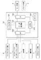
図1は本発明の実施の形態に係る画像形成装置を適用した複合機(以下「MFP:Multi Function Peripheral」という)の構成を示すブロック図である。 FIG. 1 is a block diagram showing a configuration of a multifunction peripheral (hereinafter referred to as “MFP: Multi Function Peripheral”) to which an image forming apparatus according to an embodiment of the present invention is applied.
図1において、リーダ部1は原稿上の画像をCCD等のイメージセンサにより光電的に読み取り、原稿に応じた画像データ(画像情報)を画像入出力制御部3へ出力する。プリンタ部2は、例えば、レーザビームプリンタであって、画像入出力制御部3からの画像データに応じた画像を用紙(記録媒体)上に形成する。画像入出力制御部3は、リーダ部1及びプリンタ部2に接続されており、ファクシミリ部4、ストレージ部5、ネットワークインターフェース部7、RIP(RasterImageProcessor)部8、操作部9及びコア部10を備えている。
In FIG. 1, a reader unit 1 photoelectrically reads an image on a document by an image sensor such as a CCD, and outputs image data (image information) corresponding to the document to an image input /
ファクシミリ部4は電話回線を介して受信した圧縮画像データを伸長して、該伸長された画像データをコア部10へ転送し、又コア部10から転送された画像データを圧縮して、該圧縮された圧縮画像データを電話回線を介して相手先に送信する。送受信する画像データは、ストレージ部5に接続されたハードディスク6中に一時的に保存することができる。
The
ストレージ部5にはハードディスク6が接続されており、ストレージ部5はコア部10から転送された画像データを圧縮し、その画像データを検索するためのID番号とともにハードディスク6に記憶させる。また、ストレージ部5はコア部10を介して転送されたコードデータに基づいてハードディスク6に記憶されている圧縮画像データを検索し、該検索された圧縮画像データを読み出して伸長し、その伸長された画像データをコア部10へ転送する。このハードディスク6は、例えば20ギガバイトの記憶容量を有し、画像の内容に左右されるが、A4サイズのカラー圧縮画像を2500ページ分記憶可能である。
A
更に、ストレージ部5は、ハードディスク6の接続の有無およびハードディスク6の故障の有無を、ハードディスクインターフェースを介したコマンド/レスポンス、および、所定データの書き込み又は読み出し、照合を行うことにより検出する。
Furthermore, the
ネットワークインターフェース部7は、パーソナルコンピュータ又はワークステーション(PC/WS)11とコア部10の間のインターフェースであり、PC/WS11と1対1のピアツーピアで接続しても、様々な機器が接続されたネットワークに接続しても良い構成となっている。
The
RIP部8は、PC/WS11から転送された画像を表すコードデータをプリンタ部2で記録できる画像データに展開するものである。コードデータには、Postscript等に代表される、プリント記述言語(PDL:PrinterDescriptionLanguage、以下PDLという)がある。
The
操作部9はタッチパネルディスプレイとハードキーを備え、ユーザインターフェースを介して、本MFPへの動作指示や動作設定等を行う。
The
コア部10は、リーダ部1、プリンタ部2、ファクシミリ部4、ストレージ部5、ネットワークインターフェース部7、RIP部8及び操作部9のそれぞれの間におけるデータの流れを制御する。
The
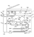
図2は、リーダ部1及びプリンタ部2の断面図である。
FIG. 2 is a cross-sectional view of the reader unit 1 and the
リーダ部1の原稿給送装置101は、ユーザにより所定の載置場所にセットされた複数枚の原稿を先頭頁又は最終頁から順番に1枚ずつプラテンガラス102上へ給送し、原稿の読み取り動作の終了後、プラテンガラス102上の原稿を所定の排出場所へ排出する。原稿がプラテンガラス102上に搬送されると、ランプ103を点灯し、スキャナユニット104の移動を開始させて、原稿を露光走査する。この時の原稿からの反射光は、ミラー105〜107及びレンズ108によってCCDイメージセンサ(以下CCDという)109へ照射される。このように、走査された原稿の画像は、CCD109によって光電変換され、電気信号データとなる。CCD109から出力される画像データは、A/D変換、シェーディング補正や色変換等、所望の画像処理が施された後、不図示の画像入出力制御部3のコア部10へ転送される。
The
プリンタ部(画像形成部)2のレーザドライバ221は、レーザ発光部201を駆動し、不図示の画像入出力制御部3のコア部10から出力された画像データに応じた光量のレーザ光を、レーザ発光部201に発光させる。このレーザ光は、感光ドラム202を照射し、感光ドラム202は、レーザ光に応じた潜像を形成する。現像器203は、この感光ドラム202の潜像した部分に現像剤(トナー)を付着させる。現像器203は、感光ドラム202に付着させる現像剤であるトナーを保持するものであり、トナーが所定量以下(例えば、満杯の10%、0%)となっていることを検知するトナー量センサ250を備えている。
The
また、レーザ光の照射開始と同期したタイミングで、カセット204又はカセット205のいずれかから記録紙を給紙ローラ211又は給紙ローラ212を経由し、給紙ローラ213を介して転写部206へ記録紙(記録媒体)を給紙し、感光ドラム202に担持(保持)された現像剤像を記録紙に転写する。現像剤が転写された記録紙は、定着部207に搬送され、定着部207の熱と圧力により現像剤を記録紙に定着させる。定着部207を通過した記録紙は排出ローラ208によって排出され、フィニッシャ220は、排出された複数枚の記録紙を束ねて仕分けを行う又は仕分けされた記録紙の所望の位置にステイプル止め処理を行う。また、両面記録が設定されている場合は、排出ローラ208の位置まで片面記録された記録紙を搬送した後、排出ローラ208の回転方向を逆転させ、フラッパ209によって再給紙搬送路210へ導く。再給紙搬送路210へ導かれた記録紙は上述したタイミングで転写部206へ給紙され、記録紙の反対面への画像記録が行われる。
In addition, at the timing synchronized with the start of laser beam irradiation, recording paper is recorded from either the
カセット204又はカセット205の近傍には、カセット204又はカセット205に積載された用紙が所定量以下となっていることを検知する用紙積載量センサ251,252が設けられている。また、ステイプル用の針が所定量以下となっていることを検知する針積載量センサ253がフィニッシャ220の内部に設けられている。
In the vicinity of the
さらに、リーダ部1は、原稿を給送するためのモータを駆動するモータ駆動制御部13を備え、プリンタ部2は、給紙ローラ212や感光ドラム202等を回転させるモータを駆動するモータ駆動制御部12を備えている。
Further, the reader unit 1 includes a motor
なお、プリンタ部2は、画像形成を行う画像形成部は画像形成可能な動作状態と画像形成不能な停止状態のいずれかの状態で動作する。そして、なお、停止状態にある画像形成部を動作状態へ移行させるためには動作状態移行処理を実行する必要があり、動作状態にある画像形成部を停止状態へ移行させるためには停止状態移行処理を実行する必要がある。
In the
ここで、動作状態移行処理及び停止状態移行処理について説明する。 Here, the operation state transition process and the stop state transition process will be described.
プリンタ部2は、動作状態においては感光ドラム202を回転させておいたり、感光ドラム202に対して所定の電圧を印加する帯電部から一定の電圧を印加しておく必要がある。そのため、停止状態にあるプリンタ部2を動作状態に移行させるには、感光ドラム202を停止状態から回転状態へ移行させる処理、帯電部への電圧印加状態を停止状態から印加状態へ移行させる処理等が必要であり、これらの処理を総称して動作状態移行処理という。なお、動作状態移行処理には、所定の動作状態移行時間を要する。
In the operating state, the
また、プリンタ部2は、停止状態においては感光ドラム202上にトナーが残存しない状態とする必要があり、またカラー画像を形成する際の各色の濃度が所望の濃度となるように設定されている必要がある。そのため、動作状態にあるプリンタ部2を停止状態に移行させるには、感光ドラム202上に残存したトナーを回収するクリーニング処理(例えば、感光ドラム202を少なくとも1周以上回転させることで、感光ドラムの周上に1箇所設けられたクリーニング部材によるクリーニングを行う)を実行する必要がある。また、画像形成を再開する際に各色の濃度が所望の濃度となるように濃度設定処理(例えば、特定の画像情報に基づいて感光ドラム202上にトナー像を形成し、センサにて各色のトナー像の濃度を検出し、その検出結果に基づいて各色の濃度設定をする処理)を実行する必要がある。これらの処理を総称して停止状態移行処理といい、停止状態移行処理には、所定の停止状態移行時間を要する。
Further, the
図3は、コア部10の構成を示すブロック図である。
FIG. 3 is a block diagram illustrating a configuration of the
リーダ部1から受信された画像データはインターフェース122を介してデータ処理部121へ送信される。データ処理部121は、画像の回転処理や変倍処理等の画像処理や画像データの圧縮や伸長を行うものであり、所定の画像データを所定量記憶可能なページメモリ125と接続されている。データ処理部121は、リーダ部1から入力された画像データをページメモリ125に一時的に記憶した後、圧縮してインターフェース120を介してストレージ部5へ送信する。
The image data received from the reader unit 1 is transmitted to the
また、ネットワークインターフェース部7を介して入力された画像を表すコードデータ(PDL)は、インターフェース120を介してデータ処理部121に送信した後、インターフェース120を介してRIP部8へ一旦返送する。RIP部8では、受信したコードデータを画像データに変換し、この変換した画像データを再度データ処理部121に送信する。データ処理部121は、RIP部8から受信した画像データをページメモリ125に一時的に記憶した後、圧縮してストレージ部5へ送信する。
Further, code data (PDL) representing an image input via the
ファクシミリ部4から入力された画像データは、インターフェース120を介してデータ処理部121に送信した後、ページメモリ125に一時的に記憶し、圧縮してストレージ部5へ送信される。
The image data input from the
また、ストレージ部5から入力された画像データは、インターフェース120を介してデータ処理部121へ送信した後、伸長してページメモリ125に一時的に記憶した後、プリンタ部2、ファクシミリ部4又はネットワークインターフェース部7へ送信される。
The image data input from the
尚、コア部10は、前述したデータ処理部121へ各種画像データを送信し、ページメモリ125に一時的に記憶した後、ストレージ部5へ画像データを送信するだけでなく、プリンタ部2やファクシミリ部4、ネットワークインターフェース部7へ送信することも、送信先の複数の組み合わせも、内部のセレクタ切り替えにより実行可能である。
The
CPU123は、メモリ124に記憶されている制御プログラム、および操作部9から受信した制御コマンドに基づいて上記各種動作の制御を行う。また、メモリ124はCPU123の作業領域としても使われる。
The
このように、コア部10を中心に、データ処理部121及びページメモリ125を介して、原稿画像の読み取り、画像のプリント出力、画像の送受信、画像の保存及びコンピュータからのデータの入出力などの機能を複合させた処理が実行可能である。
As described above, the document image reading, the image print output, the image transmission / reception, the image storage, the data input / output from the computer, etc. through the
また、上記の例においては、ストレージ部5が機器内にある構成であるが、ネットワークを介した外部にあるサーバに記憶する形態であっても構わない。
In the above example, the
次に、コア部10のCPU123で実行されるジョブ制御について、MFPのすべての構成部が正常動作している場合の例を図4を用いて説明する。図4は、ジョブ制御を説明するためのブロック図であり、ジョブ制御の単位を論理的に示したものである。
Next, job control executed by the
ジョブ制御の単位は、1以上のページ数で構成された1まとまりの画像データに対する入力及び出力処理である。また、制御されるジョブの種類は、画像入力ジョブと画像出力ジョブに大別される。 The unit of job control is input and output processing for a group of image data composed of one or more pages. The types of jobs to be controlled are roughly divided into image input jobs and image output jobs.
画像入力ジョブは、リーダ部1で読み取った画像データを順次ストレージ部5へ記録する画像入力ジョブ411、RIP部8で展開された画像データを順次ストレージ部5へ記録する画像入力ジョブ412、ファクシミリ部4−1で受信された画像データを順次ストレージ部5へ記録する画像入力ジョブ413、及びネットワークインターフェース部7−1から入力された画像データを順次ストレージ部5へ記録する画像入力ジョブ414にさらに分類される。
The image input job includes an
画像出力ジョブは、ストレージ部5から読み出した画像データを順次プリンタ部2へ出力する画像出力ジョブ401、ストレージ部5から読み出した画像データを順次ファクシミリ部4−2へ出力する画像出力ジョブ403、及びストレージ部5から読み出した画像データを順次ネットワークインターフェース部7−2へ出力する画像出力ジョブ404に分類される。
The image output job includes an
尚、ファクシミリ部4−1は、ファクシミリ部4のデータ受信機能を示し、ファクシミリ部4−2は、ファクシミリ部4のデータ送信機能を示す。また、ネットワークインターフェース部7−1は、ネットワークインターフェース部7のデータ受信機能を示し、ネットワークインターフェース部7−2は、ネットワークインターフェース部7のデータ送信機能を示す。
Note that the facsimile unit 4-1 indicates a data reception function of the
図5は、複数のジョブを組み合わせた単位の複数の例を示す図である。この複数のジョブを組み合わせた1つの単位を「セッション」という。 FIG. 5 is a diagram illustrating a plurality of examples of units obtained by combining a plurality of jobs. One unit obtained by combining a plurality of jobs is referred to as a “session”.
同図において、501はPDLプリントセッションであり、画像入力ジョブ412と画像出力ジョブ401とを組み合わせたセッションとして制御される。502はコピーセッションであり、画像入力ジョブ411と画像出力ジョブ401とを組み合わせたセッションとして制御される。503はファクシミリ送信セッションであり、画像入力ジョブ411と画像出力ジョブ403とを組み合わせたセッションとして制御される。504はファクシミリ受信セッションであり、画像入力ジョブ413と画像出力ジョブ401とを組み合わせたセッションとして制御される。505はスキャンセッションであり、画像入力ジョブ411と画像出力ジョブ404とを組み合わせたセッションとして制御される。
In the figure,
尚、セッションは1つ以上のジョブを含む制御単位であり、図5に示した以外に、例えば画像入力ジョブ412を1セッションとして扱ったり、また、画像出力ジョブ401を1セッションとして扱ったり、画像入力ジョブ412と画像出力ジョブ401と画像出力ジョブ403の3つのジョブを組み合わせて1セッションとして扱っても良い。
Note that a session is a control unit including one or more jobs. In addition to those shown in FIG. 5, for example, the
図6は、MFPのすべての構成部が正常動作している場合において、コア部10のCPU123で実行されるセッション制御およびジョブ制御の手順の例として、図5のPDLプリントセッション501とそれを構成する画像入力ジョブ412および画像出力ジョブ401の制御手順を示したフローチャートである。
FIG. 6 shows the
同図において、S601〜S630は各ステップを示し、セッション制御(a)、画像入力ジョブ制御(b)および画像出力ジョブ制御(c)は、それぞれ1つの作業単位(タスク)として動作し、各々は、その依存関係を維持しながら、同時並列的にマルチタスク動作する。 In the figure, S601 to S630 represent steps, and session control (a), image input job control (b), and image output job control (c) each operate as one unit of work (task). Multitasking is performed simultaneously in parallel while maintaining the dependency.
まず、セッション制御(a)では、ユーザは、PC/WS11のキーボードやマウスなどの入力デバイスを用いてプリント設定を行う。プリント設定内容は、ページ数、部数、原稿サイズ、用紙サイズ、拡大縮小率、片面/両面、レイアウト、ページ出力順序、ソートモード等である。ここでは、一例として、以下のプリント設定がなされているものとする。
First, in session control (a), a user performs print settings using an input device such as a keyboard or mouse of the PC /
ページ数:20頁…(P1)
印刷部数:10部…(P2)
片面印刷:する…(P3)
原稿サイズ:A4…(P4)
用紙サイズ:A4…(P5)
拡大縮小率:100%…(P6)
レイアウト:しない…(P7)
ページ出力順序:昇順…(P8)
ソートモード:する…(P9)
上記設定が完了すると、ユーザはPC/WS11から画像入出力制御部3に印刷指示を与える。それと共にPC/WS11上にインストールされているドライバソフトウエアは、印刷対象となるドキュメントを、PDLデータに変換して、設定したプリント設定パラメータ(P1)〜(P9)とともに、PC/WS11に接続したインターフェース経由で、ネットワークインターフェース部7に送信する。
Number of pages: 20 pages ... (P1)
Number of copies: 10 copies (P2)
Single-sided printing: Yes ... (P3)
Original size: A4 (P4)
Paper size: A4 (P5)
Enlargement / reduction ratio: 100% (P6)
Layout: No ... (P7)
Page output order: ascending order (P8)
Sort mode: Yes ... (P9)
When the above setting is completed, the user gives a print instruction from the PC /
ネットワークインターフェース部7を介して入力されたPDLデータは、データ処理部121に転送された後、RIP部8へ転送され、RIP部8は、PDLデータを順次画像データに変換・展開(ラスタライズ)する。RIP部8でPDLデータを受信開始すると、RIP部8からコア部10へ処理要求が発行される。コア部10では発行された処理要求をCPU123が受付ける(ステップS601)。ここで、ユーザが設定したプリント設定パラメータ(P1)〜(P9)もCPU123へ送信される。
The PDL data input via the
次に、ステップS602では、コア部10において、RIP部8から発行された処理要求に従った一単位の画像処理機能を少なくとも1つの画像入力ジョブ又は画像出力ジョブに分け、これらの画像入力ジョブ又は画像出力ジョブにより構成されるセッションを生成し、管理する。図7にセッション管理テーブル700を示す。セッション生成では、図7に示すセッション管理テーブル700をメモリ124上に作成し、各種情報をセッションが終了するまで保持する。
In step S602, the
セッションIDフィールド701はMFP中でのユニークなセッションIDを生成して保持するものである。セッションタイプフィールド702は生成されたセッションのタイプ(PDLプリントセッション、コピーセッション、ファクシミリ送信セッション、ファクシミリ受信セッション、又はスキャンセッション等)を特定するものであり、本動作例ではPDLプリントセッション501であることを記録しておく。セッション優先順位フィールド703は、当該セッションの処理順序に関する優先順位を保持するものである。セッションステータスフィールド704は当該セッションの実行状態(実行可能状態、実行状態、中断状態、終了状態又はエラー状態等)を保持するものである。リンクジョブ数フィールド705は当該セッションを構成する画像入力ジョブおよび画像出力ジョブの構成数を保持するものであり、本動作例では、図5に示す如くPDLプリントセッション501を構成する画像入力ジョブ412と画像出力ジョブ401の2つのジョブからなるので、構成数として「2」が設定される。第1のジョブポインタフィールド706は、画像入力ジョブ412のジョブ管理テーブル710へのポインタである。また、第2のジョブポインタフィールド707は、画像出力ジョブ401のジョブ管理テーブル730へのポインタである。このジョブポインタフィールドは、セッションを構成するジョブの数分、用意される。ジョブ管理テーブルもまた、セッションを構成するジョブの数分作成される。
A
ステップS603では、図7に示す画像入力ジョブ412のジョブ管理テーブル710をメモリ124上に作成し(即ち画像入力ジョブ412の生成)、各種情報をジョブが終了するまで保持する。
In step S603, a job management table 710 of the
ジョブIDフィールド711はMFP中でのユニークなジョブIDを生成して保持するものである。ジョブタイプフィールド712は生成されたジョブのタイプ(前述した画像入力ジョブおよび画像出力ジョブ)を特定するものであり、本動作例では、RIP部8で展開された画像データを順次ストレージ部5へ記録する画像入力ジョブ412であることを記録しておく。ジョブ優先順位フィールド713は、当該ジョブの処理順序に関する優先順位を保持するものである。ジョブステータスフィールド714は、当該ジョブの実行状態(実行可能状態、実行状態、中断状態、終了状態又はエラー状態等)を保持するものである。ページ数フィールド715は、当該ジョブのページ数を保持するものである。ページポインタフィールド716は、当該ジョブが管理する各ページの詳細情報を記述するページ管理テーブル720へのポインタである。ページ管理テーブル720はハードディスク6上に記録される。
A
ジョブパラメータフィールド717は当該ジョブの各種設定パラメータを保持するものであり、本動作例ではステップS601で設定された、プリント設定パラメータ(P1)〜(P9)の設定内容が保持される。
The
また、セッション制御(a)では、以上の画像入力ジョブのジョブ管理テーブル710を作成後、画像入力ジョブ制御(b)を起動させる。 In the session control (a), the image input job control (b) is started after the job management table 710 for the above image input job is created.
ステップS604では、図7に示す画像出力ジョブ401のジョブ管理テーブル730をメモリ124上に作成し(即ち画像出力ジョブ401の生成)、各種情報をジョブが終了するまで保持する。
In step S604, a job management table 730 of the
ジョブIDフィールド731はMFP中でのユニークなジョブIDを生成して保持するものである。ジョブタイプフィールド732は生成されたジョブのタイプ(前述した画像入力ジョブおよび画像出力ジョブ)を特定するものであり、本動作例では、ストレージ部5に記録された画像データを順次プリンタ部2へプリントアウトする画像出力ジョブ401であることを記録しておく。ジョブ優先順位フィールド733は、当該ジョブの処理順序に関する優先順位を保持するものである。ジョブステータスフィールド734は、当該ジョブの実行状態(実行可能状態、実行状態、中断状態、終了状態又はエラー状態等)を保持するものである。ページ数フィールド735は、当該ジョブのページ数を保持するものである。ページポインタフィールド736は、当該ジョブが管理する各ページの詳細情報を記述するページ管理テーブル740へのポインタである。ページ管理テーブル740の実体は、画像入力ジョブ412に関してハードディスク6上に記録されたページ管理テーブル720と同一のものである。
A
ジョブパラメータフィールド737は、当該ジョブの各種設定パラメータを保持するものであり、本動作例ではステップS601で設定された、ページ数、部数、用紙サイズ、拡大縮小率、片面/両面、ページ出力順序及びソート出力等に関するパラメータ(P1)〜(P9)が保持される。
The
また、セッション制御(a)は、以上の画像出力ジョブのジョブ管理テーブル730を作成後、画像出力ジョブ制御(c)を起動させる。 The session control (a) activates the image output job control (c) after creating the job management table 730 for the image output job.
ステップS605では、生成した画像入力ジョブ412の処理を開始する。即ち、セッション制御(a)から画像入力ジョブ制御(b)に対してジョブの開始を指示する。
In step S605, processing of the generated
ステップS606では、生成した画像出力ジョブ401の処理を開始する。即ち、セッション制御(a)から画像出力ジョブ制御(c)に対してジョブの開始を指示する。
In step S606, processing of the generated
ステップS607では、画像入力ジョブ制御(b)から、ジョブの終了通知を受信して、画像入力ジョブの終了処理を行う。即ち、画像入力ジョブのジョブ管理テーブル710のジョブステータス714を終了状態にする。
In step S607, a job end notification is received from the image input job control (b), and the end processing of the image input job is performed. That is, the
ステップS608では、画像出力ジョブ制御(c)から、ジョブの終了通知を受信して、画像出力ジョブの終了処理を行う。即ち、画像出力ジョブのジョブ管理テーブル730のジョブステータス734を終了状態にする。
In step S608, a job end notification is received from the image output job control (c), and an image output job end process is performed. That is, the
ステップS609では、セッションの終了処理を行う。即ち、画像入力ジョブおよび画像出力ジョブのジョブ管理テーブル710、730と、ページ管理テーブル720、740のページ毎の画像データを破棄して資源を開放するとともに、セッション管理テーブル700も破棄し、資源を開放して一連の処理を終了する。 In step S609, session termination processing is performed. That is, the image data for each page in the job management tables 710 and 730 for the image input job and the image output job and the page management tables 720 and 740 are discarded to release resources, and the session management table 700 is also discarded to save resources. Open and end the series of processing.
次に、PDLプリントセッション501における画像入力ジョブ制御(b)を説明する。
Next, image input job control (b) in the
ステップS611では、画像入力ジョブ制御(b)が、セッション制御(a)からのジョブの開始指示を受けて、他の画像入力ジョブが実行されておらず、新たな画像入力ジョブの受け付け可能状態であれば、指示されたジョブの処理を開始する。 In step S611, when the image input job control (b) receives a job start instruction from the session control (a), no other image input job is executed, and a new image input job can be accepted. If there is, start processing the designated job.
ステップS612では、RIP部8で展開された画像データ1ページの受信を行う。即ち、RIP部8からインターフェース120を介してデータ処理部121への画像転送を行う。
In step S612, one page of image data expanded by the
ステップS613では、データ処理部121に転送された画像データをページメモリ125に一時的に記憶する。
In step S613, the image data transferred to the
ステップS614では、画像出力ジョブ制御(c)に対してページ出力要求を送信する。後述する画像出力ジョブ制御(c)にて、当該ページの画像データのページメモリ125からの読み出しが終了したら、ステップS615に進む。
In step S614, a page output request is transmitted to the image output job control (c). When the image output job control (c) described later finishes reading the image data of the page from the
ステップS615では、ページメモリ125中に一時的に記憶された画像データをストレージ部5のハードディスク6に記録する。この時、ページ管理テーブル720中のページ1フィールド721に各種画像属性情報(解像度、画素数等)を記録する。
In step S615, the image data temporarily stored in the
ステップS616ではRIP部8にて展開された処理すべき全てのページが画像データとしてハードディスク6に記録されたかどうかが判断される。ここでの判断の結果、処理されていないページが残っている場合は、処理をステップS612に戻し、また、全てのページが処理された場合には、処理をステップS617に進める。
In step S616, it is determined whether all the pages to be processed developed in the
ステップS617では、セッション制御(a)に画像入力ジョブの終了通知を送信し、画像入力ジョブ制御(b)を終了する。これにより、画像入力ジョブのジョブ管理テーブル710のジョブステータス714は終了状態となる。
In step S617, an end notification of the image input job is transmitted to the session control (a), and the image input job control (b) is ended. As a result, the
次にPDLプリントセッションにおける画像出力ジョブ制御(c)について説明する。 Next, image output job control (c) in the PDL print session will be described.
ステップS621では、画像出力ジョブ制御(c)が、セッション制御(a)からこのジョブの開始指示を受けて、プリンタ部2が他のジョブにより使用されておらず、新たなプリント動作可能状態であれば、指示されたジョブを開始する。
In step S621, the image output job control (c) receives this job start instruction from the session control (a), and the
ステップS622では、画像入力ジョブ制御(b)から、ページメモリ125に一時的に記憶された画像データの出力要求を受信する。
In step S622, an output request for image data temporarily stored in the
ステップS623では、ページメモリ125からの画像データの読み出しを開始する。
In step S623, reading of image data from the
ステップS624では、プリンタ部2の使用権を獲得後、パラメータフィールド737で設定されている出力パラメータ(P1)〜(P9)に基づき、MFPにおける出力経路を設定する。ここでは、仮にその経路情報を、上段カセット204→給紙ローラ211→給紙ローラ213→感光ドラム202→定着機207→排紙ローラ208→フィニッシャとする。読み出したページの画像データを、インターフェース122を介してプリンタ部2へ画像転送し、プリンタ部2で前述したように画像形成を行いプリントアウトする。
In step S624, after acquiring the right to use the
ステップS625では、画像入力ジョブ制御(b)からのページ出力要求が最終ページか否かを判断する。個々での判断の結果、処理されていないページが残っている場合は、処理をステップS622に戻し、また、全てのページが処理された場合には、処理をステップS626に進める。ここまでの処理で、パラメータ(P1)にて設定された印刷部数10のうち、最初の1部が完了する。この段階で、必要に応じステイプル処理をプリント出力に対して実行してもよい。 In step S625, it is determined whether the page output request from the image input job control (b) is the last page. As a result of the individual determination, if there is a page that has not been processed, the process returns to step S622. If all pages have been processed, the process proceeds to step S626. By the processing so far, the first one of the ten copies set by the parameter (P1) is completed. At this stage, a stapling process may be performed on the print output as necessary.
ステップS626では、画像入力ジョブ制御(b)のステップS615でストレージ部5のハードディスク6に記録されたページ毎の画像データを順次読み出して、インターフェース120を介してデータ処理部121に画像転送する。データ処理部121では、転送された1ページ分の画像データをページメモリ125上に保持する。
In step S626, the image data for each page recorded in the
ステップS627では、プリンタ部2の使用権を獲得後、データ処理部121に転送されてページメモリ125に保持されている画像データをインターフェース122を介してプリンタ部2へ転送し、プリンタ部2で画像形成を行いプリントアウトする。
In step S 627, after acquiring the right to use the
ステップS628では、ハードディスク6に記録されたページ毎の画像データが全てプリントアウトされたかどうかが判断される。ここでの判断の結果、処理されていないページが残っている場合は、処理をステップS626に戻し、また、全てのページが処理された場合には、ステイプル指示がされているので、プリンタ部2で1部の用紙のステイプル止めをして、処理をステップS629に進める。
In step S628, it is determined whether all the image data for each page recorded on the
ステップS629では、ステップS601にて設定されたプリント部数が全てプリントアウトされたかどうかが判断される。ここでの判断の結果、処理されていない部数が残っている場合は、処理をステップS626に戻し、ハードディスク6から画像データを読出し、ページメモリ125への格納、プリンタ部2でのプリントアウトを実行する。また、全ての部数が処理された場合には、処理をステップS630に進める。
In step S629, it is determined whether all the print copies set in step S601 have been printed out. If it is determined that the number of unprocessed copies remains, the process returns to step S626, image data is read from the
ステップS630では、セッション制御(a)に画像出力ジョブの終了通知を送信し、画像出力ジョブ制御(c)を終了する。これにより、画像出力ジョブのジョブ管理テーブル730のジョブステータス734は終了状態となる。
In step S630, an end notification of the image output job is transmitted to the session control (a), and the image output job control (c) is ended. As a result, the
以上の例では、PC/WS11上で設定したプリント設定に従って、PC/WS11からPDLデータとして画像情報を転送し、本MFPでPDLデータを画像データに展開してプリント出力する制御形態のPDLプリントセッション501について説明した。この一連の制御は、リーダ部1で読み取られた画像情報をプリント出力する図7のコピーセッション502の場合についても同様に適用することが可能である。
In the above example, according to the print settings set on the PC /
以下に、図6を用いて、セッション制御およびジョブ制御の第2の例として、図5のコピーセッション502と、これを構成するリーダ部1で読み取られた画像データを順次ストレージ部5へ記録する画像入力ジョブ411およびストレージ部5に記録された画像データを順次プリンタ部2へプリントアウトする画像出力ジョブ401の制御手順を説明する。
Hereinafter, as a second example of session control and job control, the
まず、セッション制御(a)では、ユーザは、画像入出力制御部3の操作部9上でコピー動作のための各種設定を行う。
First, in session control (a), the user performs various settings for a copy operation on the
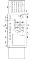
図8は、操作部9の外観を示す図である。ここで、操作部9は、電源キー801、予熱キー802、コピー機能選択キー803、ファクシミリ機能選択キー804、パーソナルボックス機能選択キー805、スタートキー806、ストップキー807、リセットキー808、操作ガイドキー809、ユーザモード設定キー810、割込みコピーキー811、テンキー812、クリアキー813、ファクシミリワンタッチキー814、ワンタッチキーの切り替え蓋815及びタッチパネル816を備えている。
FIG. 8 is a diagram illustrating an appearance of the
コピー動作のための各種設定内容は、部数、用紙サイズ、拡大縮小率、片面/両面、ソート出力等であり、テンキー812およびタッチパネル816上に表示される設定項目に従ってユーザが入力する。ここでは、一例として、以下のコピー設定がなされているものとする。
Various setting contents for the copy operation are the number of copies, paper size, enlargement / reduction ratio, single-sided / double-sided, sort output, and the like, and are input by the user according to setting items displayed on the
コピー部数:10部…(C1)
片面コピー:する…(C2)
用紙サイズ:A4…(C3)
拡大縮小率:100%…(C4)
レイアウト:しない…(C5)
ソートモード:する…(C6)
以上のコピー設定後、ユーザは原稿をリーダ部1に載置して、スタートキー806を押下してコピー指示を与える。操作部9は設定したコピー設定パラメータ(C1)〜(C7)と共に処理要求をコア部10のCPU123に転送し、これらをCPU123が受付ける(ステップS601)。
Number of copies: 10 copies (C1)
Single-sided copy: Yes ...
Paper size: A4 (C3)
Enlargement / reduction ratio: 100% (C4)
Layout: No ... (C5)
Sort mode: Yes ... (C6)
After the above copy setting, the user places the document on the reader unit 1 and presses the
次に、ステップS602では、コア部10において、操作部9から発行された処理要求に従った一単位の画像処理機能を少なくとも1つの画像入力ジョブ又は画像出力ジョブに分け、これら画像入力ジョブ又は画像出力ジョブにより構成されるセッションを生成し、上述した図7のセッション管理テーブル700で管理し、各種情報をセッションが終了するまで保持する。
In step S602, the
ステップS603では、画像入力ジョブ411のジョブ管理テーブル710をメモリ124上に作成し(即ち画像入力ジョブ411の生成)、各種情報をジョブが終了するまでの保持する。ここで、図7のジョブパラメータフィールド717は当該ジョブの各種設定パラメータを保持するものであり、本動作例ではステップS601で設定された、コピー設定パラメータ(C1)〜(C7)の設定内容が保持される。
In step S603, the job management table 710 of the
また、セッション制御(a)は、画像入力ジョブのジョブ管理テーブル710を作成後、画像入力ジョブ制御(b)を起動させる。 The session control (a) activates the image input job control (b) after creating the job management table 710 of the image input job.
ステップS604では、画像出力ジョブ401のジョブ管理テーブル730をメモリ124上に作成し、各種情報をジョブが終了するまで保持する。ジョブパラメータフィールド737は、当該ジョブの各種設定パラメータを保持するものであり、本実施の形態では、ステップS601で設定された、部数、用紙サイズ、拡大縮小率、片面/両面、ソート出力、ステイプル止めの有無等に関するパラメータ(C1)〜(C7)が保持される。
In step S604, a job management table 730 for the
また、セッション制御(a)は画像出力ジョブのジョブ管理テーブル730を作成後、画像出力ジョブ制御(c)を起動させる。 The session control (a) activates the image output job control (c) after creating the job management table 730 for the image output job.
ステップS605では、生成した画像入力ジョブ411の処理を開始する。即ち、セッション制御(a)から画像入力ジョブ制御(b)に対してジョブの開始を指示する。
In step S605, processing of the generated
ステップS606では、生成した画像出力ジョブ401の処理を開始する。即ち、セッション制御(a)から画像出力ジョブ制御(c)に対してジョブの開始を指示する。
In step S606, processing of the generated
ステップS607では、画像入力ジョブ制御(b)から、ジョブの終了通知を受信して、画像入力ジョブの終了処理を行う。即ち、画像入力ジョブのジョブ管理テーブル710のジョブステータス714を終了状態にする。
In step S607, a job end notification is received from the image input job control (b), and the end processing of the image input job is performed. That is, the
ステップS608では、画像出力ジョブ制御(c)から、ジョブの終了通知を受信して、画像出力ジョブの終了処理を行う。即ち、画像出力ジョブのジョブ管理テーブル730のジョブステータス734を終了状態にする。
In step S608, a job end notification is received from the image output job control (c), and an image output job end process is performed. That is, the
ステップS609では、セッションの終了処理を行う。即ち、画像入力ジョブおよび画像出力ジョブのジョブ管理テーブル710,730と、ページ管理テーブル720,740のページ毎の画像データを破棄して資源を開放するとともに、セッション管理テーブル700も破棄し、資源を開放して一連の処理を終了する。
In step S609, session termination processing is performed. That is, the
コピーセッション502における画像入力ジョブ制御(b)について説明する。
The image input job control (b) in the
ステップS611では、画像入力ジョブ制御(b)が、セッション制御(a)からジョブの開始指示を受けて、他の画像入力ジョブによってリーダ部1が使用されておらず、新たな画像入力ジョブの受け付け可能状態であれば、指示されたジョブを開始する。リーダ部1の使用権を獲得後、パラメータフィールド737で設定されている出力パラメータ(P1)〜(P7)に基づき、MFPにおける入力経路を設定する。ここでは、仮にその入力経路情報を、原稿給送装置101→プラテンガラス→排出トレイとする。
In step S611, the image input job control (b) receives a job start instruction from the session control (a), the reader unit 1 is not used by another image input job, and a new image input job is accepted. If so, start the indicated job. After acquiring the right to use the reader unit 1, the input path in the MFP is set based on the output parameters (P1) to (P7) set in the
ステップS612では、リーダ部1で読み取られた画像データ1ページの受信を行う。即ち、リーダ部1からインターフェース120を介してデータ処理部121への画像転送を行う。
In step S612, one page of image data read by the reader unit 1 is received. That is, image transfer from the reader unit 1 to the
ステップS613では、データ処理部121に転送された画像データをページメモリ125に一時的に記憶する。
In step S613, the image data transferred to the
ステップS614では、画像出力ジョブ制御(c)に対してページ出力要求を送信する。画像出力ジョブ制御(c)にて、当該ページの画像データのページメモリ125からの読み出しが終了したら、ステップS615に進む。
In step S614, a page output request is transmitted to the image output job control (c). When the image output job control (c) finishes reading the image data of the page from the
ステップS615では、ページメモリ125中に一時的に記憶された画像データをストレージ部5のハードディスク6に記録する。この時、ページ管理テーブル720中のページ1フィールド721に各種画像属性情報(解像度、画素数等)を記録する。
In step S615, the image data temporarily stored in the
ステップS616では、リーダ部1で読み取られた処理すべき全てのページが画像データとしてハードディスク6に記録されたかどうかが判断される。ここでの判断の結果、処理されていないページが残っている場合は、処理をステップS612に戻し、また、全てのページが処理された場合には、処理をステップS617に進める。
In step S616, it is determined whether all the pages to be processed read by the reader unit 1 have been recorded on the
ステップS617では、セッション制御(a)に画像入力ジョブの終了通知を送信し、画像入力ジョブ制御(b)を終了する。これにより、画像入力ジョブのジョブ管理テーブル710のジョブステータス714は終了状態となる。
In step S617, an end notification of the image input job is transmitted to the session control (a), and the image input job control (b) is ended. As a result, the
コピーセッション502における画像出力ジョブ制御(c)のステップS621以降の処理は、前述したPDLプリントセッション501の場合と全く同様なので省略する。
The processing after step S621 of the image output job control (c) in the
以上の例では、PDLプリントセッション501とコピーセッション502の制御手順について説明したが、図7にセッションの拡張例を示したように、任意の画像入力ジョブと任意の画像出力ジョブを組み合わせて任意のセッションを構成しても、上記制御手順をそれらセッションに対して同様に適用することが可能である。
In the above example, the control procedure of the
次に、MFPのエラー制御について説明する。 Next, error control of the MFP will be described.
リーダ部1やプリンタ部2における入出力メディアは、紙で構成されており、様々な要因により紙が正常に排出されずに、紙詰まり状態(ジャム)になることがある。
The input / output media in the reader unit 1 and the
MFPは、リカバリ(復帰)までに必要とされる標準的な手順や時間を管理データとしてメモリ124に管理しており、ジャムが発生した場合には発生個所に応じて、管理データより復帰までの手順を操作部9に表示する。
The MFP manages the standard procedure and time required for recovery (recovery) in the
また、プリンタ部2をエラーにより停止させないために、代替経路優先モードの設定を行うことができる。このモードは、エラーが起こった個所を迂回する経路が存在する場合には、迂回経路へ切り替えることにより、リーダ部1やプリンタ部2の動作を止めることなく、セッションを継続することを優先するモードである。特にこのモードにおいては、エラーが発生した場合に、操作部9に管理データから得られた復帰までの標準復帰時間を表示すると共に、ユーザによって操作部9を介して入力された復帰までの復帰予測時間を受け付ける。
Further, in order to prevent the
これにより、復帰までに必要とされる標準復帰時間よりも短時間の復帰予測時間を設定することができ、当該設定された復帰予測時間に基づいて復帰までの処理が可能となるため、エラー箇所に応じてリーダ部1やプリンタ部2の停止時間を短くすることができる。
As a result, it is possible to set a predicted recovery time shorter than the standard recovery time required until recovery, and processing up to recovery can be performed based on the set predicted recovery time. Accordingly, the stop time of the reader unit 1 and the
コピーセッション502の制御手順におけるステップS611において、リーダ部1の原稿給送装置101における給紙ローラなどの経年劣化によりジャムが発生した場合には、コア部10のCPU123では、メモリ124に格納された入力経路情報を確認する。本MFPの原稿給送装置101では代替経路を設定することができないが、代替経路が確保できる場合は、管理データに基づいて復帰までの標準復帰時間と復帰手順を操作部9に対して表示するだけでなく、代替経路の優先モードが設定されている場合には、即座に代替経路に切り替える。
In step S611 in the control procedure of the
また、原稿給送装置101における給紙ローラなどの経年劣化によりジャムが発生した場合に、プリンタ部2に問題がなければ、コピーセッション502を中断して、別のPDLセッションを割り込みセッションとして起動することも可能である。エラーが軽度であれば、代替経路への優先モードが設定されていなくても、操作部9から標準復帰時間よりも短時間である復帰までの復帰予測時間を入力し、速やかに復帰することで、プリンタ部2の動作をほとんど止めることなくセッションを継続することができる。
Further, when a jam occurs due to aged deterioration of a paper feed roller or the like in the
PDLセッション501とコピーセッション502における画像出力ジョブ制御(c)のステップS621以降において、給紙ローラ211で給紙ジャムが起こったときに、
代替経路の優先モードが設定されている場合には、コア部10のCPU123において、プリンタ部2の迂回経路を検索し、給紙ローラ212を使用する迂回経路に切り替えて、セッションを継続する。
In step S621 and subsequent steps of image output job control (c) in the
When the alternative route priority mode is set, the
給紙ローラ213、感光ドラム202、定着部207及び排紙ローラ208等の記録媒体を搬送する搬送部材による搬送が不能となる紙詰まり(ジャム)が起こったときに、代替経路の優先モードが設定されている場合には、迂回経路がないため、管理データより復帰までの標準復帰時間と復帰手順を操作部9に対して表示し、リーダ部1に問題がなければ、PDLセッション501を中断して、別のコピーセッションの読み込み動作を割り込みセッションとして起動する。
The priority mode of the alternative path is set when a paper jam (jamming) has occurred that makes it impossible to transport the recording medium such as the
フィニッシャ220で排紙ジャムが起こったときに、代替経路の優先モードが設定されている場合には、コア部10のCPU123において、フィニッシャ220内の迂回経路を検索し、ステイプルなどのフィニッシング設定がパラメータになければ、エスケープトレイ221への迂回経路に切り替えて、セッションを継続する。
When a paper discharge jam occurs in the
図9は、コア部10のCPU123で実行されるエラー制御処理を示すフローチャートである。本処理は、コア部10のCPU123で実行される。
FIG. 9 is a flowchart showing an error control process executed by the
まず、CPU123は、MFP(画像形成装置)において、画像形成が実行不能となる要因(エラー)が発生したか否かを判別する(ステップS1001)。MFPにエラーが発生した場合、CPU123は、エラーの要因がプリンタ部2のモータの駆動を停止させる要因であるか否かを確認する(ステップS1002)。ここで、プリンタ部2のモータの駆動を停止させる要因とは、プリンタ部2のモータ駆動を維持することができない要因をいう。例えば、フィニッシャ220で排紙ジャム(紙詰まり)が発生した場合は、プリンタ部2のモータ駆動を維持することができるため、プリンタ部2のモータの駆動を停止させる要因とはならない。また、カセット204に収納された用紙の残量が所定量(例えば積載可能枚数の10%、0枚等)以下となった場合、プリンタ部2による画像形成が実行不能な要因となるものの、プリンタ部2のモータ駆動を維持することができる。
First, the
次に、CPU123は、実行中のジョブと待機中のジョブの情報収集を行い、さらにプリンタ部2の動作状態の情報収集を行う(ステップS1003)。プリンタ部2の動作状態とは、プリンタ部2が備える各種の給紙ローラや感光ドラム等を回転させるモータを駆動するモータ駆動制御部12の動作状態である。また、ステップS1003において、現在実行中のジョブと待機中のジョブの情報収集を行うのは、待機中のジョブとして現在実行中のジョブと異なる種類のジョブがある場合には、そのジョブを先に処理できることもあるからである。また、プリンタ部2の動作状態の情報収集を行うのは、エラー発生後にプリンタ部2をモータ駆動制御部12で駆動可能か否かを判断するためである。
Next, the
次いで、プリンタ部2の動作状態を維持するか否かを判別する(ステップS1004)。この判別では、操作部9に図10(A)の画面表示がなされ、「維持」ボタンが押下された場合には、後述するステップS1005の動作状態維持モードに進む。一方、「停止」ボタンが押下された場合には、後述するステップS1006の停止状態移行モードに進む。
Next, it is determined whether or not the operation state of the
ステップS1004において、動作状態維持モードが設定された場合、即ち、図10(A)の画面表示で「維持」ボタンが押下された場合には、後述する動作状態維持モードを実行する(ステップS1005)。この場合、操作部9に図10(B)の画面表示がなされ、「OK」ボタンが押下されると、動作状態維持モードを実行することになる。「戻る」ボタンが押下されると、再度操作部9に図10(A)の画面表示がなされる。
If the operation state maintenance mode is set in step S1004, that is, if the “maintain” button is pressed in the screen display of FIG. 10A, the operation state maintenance mode described later is executed (step S1005). . In this case, when the screen of FIG. 10B is displayed on the
ステップS1004において、動作状態維持モードが設定されなかった場合、即ち、図10(A)の画面表示で「停止」ボタンが押下された場合には、停止状態移行モードを実行する(ステップS1006)。停止状態移行モードとは、プリンタ部2を動作状態から停止状態へ移行させる処理である。この場合、操作部9に図10(C)の画面表示がなされ、「OK」ボタンが押下されると、停止状態移行モードを実行することになる。「戻る」ボタンが押下されると、再度操作部9に図10(A)の画面表示がなされる。この停止状態移行モードは、図10(B)の画面表示がなされ、「OK」ボタンが押下されると、前述した停止状態移行処理を実行するモードである。
If the operation state maintenance mode is not set in step S1004, that is, if the “stop” button is pressed in the screen display of FIG. 10A, the stop state transition mode is executed (step S1006). The stop state transition mode is a process for shifting the
CPU123は、ステップS1005又はステップS1006が終了した後、MFPによる画像形成が実行不能となる要因が除去されたか否かを判別し(ステップS1007)、当該要因が除去された場合には、本処理を終了する一方、当該要因が除去されなかった場合には、ステップS1002に戻る。
After step S1005 or step S1006 is completed, the
尚、上述した代替経路の優先モードは動作状態維持モードに含まれるが、以下、代替経路の優先モード以外の動作状態維持モードについて説明する。 The alternative route priority mode described above is included in the operation state maintenance mode. Hereinafter, the operation state maintenance mode other than the alternative route priority mode will be described.
図11は、用紙を搬送する搬送路上での用紙の紙詰まり(ジャム)などの、MFPによる画像形成が実行不能となる要因(エラー)により動作状態維持モードが設定された場合の処理を示すフローチャートである。本処理は、コア部10のCPU123で実行される。
FIG. 11 is a flowchart showing processing when the operation state maintenance mode is set due to a factor (error) that makes it impossible to perform image formation by the MFP, such as a paper jam (jam) on the conveyance path for conveying the paper. It is. This process is executed by the
まず、CPU123は、ステップS1002で確認したエラーの要因が、プリンタ部2のモータの駆動を維持することができる要因であるか否かを判別する(ステップS1201)。このとき、プリンタ部2のモータの駆動を維持することができる要因である場合には、操作部9に、例えば図12(A)の画面表示がなされ、プリンタ部2のモータの駆動を維持することができない要因である場合には、操作部9に例えば図12(B)の画面表示がなされる。
First, the
ステップS1201の判別の結果、プリンタ部2のモータの駆動を維持することができない要因である場合、即ち、図12(B)の画面表示で「OK」ボタンが押下された場合には、図9のステップS1007の処理に進む。
If it is determined in step S1201 that the motor drive of the
一方、ステップS1201の判別の結果、プリンタ部2のモータの駆動を維持することができる要因である場合、即ち、図12(A)の画面表示で「OK」ボタンが押下された場合には、プリンタ部の動作状態(感光ドラム202の回転をさせておく状態)を維持するか否かを判別する(ステップS1202)。このとき、操作部9に例えば図12(C)の画面表示がなされる。図12(C)の画面表示において、「維持」ボタンが押下された場合には、プリンタ部2の動作状態を維持すると判別する一方、「停止」ボタンが押下された場合には、停止状態移行処理を実行すると判別する。
On the other hand, if the result of determination in step S1201 is a factor that can maintain the drive of the motor of the
ステップS1202の判別の結果、停止状態移行処理を実行すると判別した場合、図9のステップS1007の処理に進む。一方、ステップS1202の判別の結果、プリンタ部2の動作状態を維持すると判別した場合、エラー要因を除去するのに要する経過時間の入力を待つ(ステップS1203)。この経過時間は、MFPの操作者が操作部9を介して入力する値であり、操作者がエラー要因を除去するのにどの程度の時間を要するのかを鑑みて入力する値である。このとき、操作部9に例えば図12(D)の画面表示がなされる。図12(D)の画面表示では、空欄に経過時間(エラー要因が発生してからエラー要因を除去するまでに要する時間)を入力し、「OK」ボタンを押下することで、経過時間がCPU123に設定される。「clear」ボタンを押下すると空欄に入力された経過時間が消去される。なお、ステップS1203では、経過時間を操作者が入力するものとしたが、MFPのストレージ部5等に予め記憶された値を自動的に入力するようにしても良い。この場合、エラー要因(給紙部における用紙の紙詰まり、排紙部における用紙の紙詰まり、用紙の不足、トナーの不足等)に応じて各々異なる経過時間を予めストレージ部5に記憶させておき、ステップS1203では、図9のステップ1002にて確認したエラー要因に基づいてストレージ部5から読み出した経過時間を入力するようにしても良い。
If it is determined in step S1202 that the stop state transition process is to be executed, the process proceeds to step S1007 in FIG. On the other hand, if it is determined in step S1202 that the operation state of the
次いで、設定された経過時間に応じて画像形成速度を減速させる処理を実行するか否かを判別する(ステップS1204)。 Next, it is determined whether or not to execute a process of reducing the image forming speed in accordance with the set elapsed time (step S1204).
ステップS1204の判別の結果、画像形成速度を減速させる処理を実行する場合には、画像形成速度を、例えば、通常の画像形成速度の半分に減速し(ステップS1205)て操作部9に例えば図12(E)の表示をし、ステップS1206の処理に進む一方、画像形成速度を減速させる処理を実行しない場合には、ステップS1205の処理をスキップして、ステップS1206の処理に進む。なお、画像形成速度を減速させる処理を実行できるのは、エラーの要因が特定の要因である場合に限られる。例えば、カセット204から給紙させると指定されたジョブの実行中に、カセット204に収納される用紙の残量がカセット204への用紙の最大積載枚数の10%を下回った場合等である。用紙の紙詰まり(ジャム)等の画像形成速度を減速させる処理を実行できないエラーの要因である場合は、図12(E)の画面表示をすることなくステップS1206へ進むものとする。また、画像形成速度は、ステップS1203にて入力された経過時間に基づいて決定してもよい。例えば、カセット204に収納される用紙の残量がカセット204への用紙の最大積載枚数の10%である場合には、入力された経過時間までに最大積載枚数の10%に相当する枚数の用紙が無くならないように、画像形成速度を決定すればよい。
As a result of the determination in step S1204, when the process of reducing the image forming speed is executed, the image forming speed is reduced to, for example, half the normal image forming speed (step S1205), and the
次いで、エラー要因が除去され、プリンタ部2による画像形成を再開できるか否かを判別し(ステップS1206)、画像形成を再開できない場合には、ステップS1208へ進み、画像形成を再開できる場合には、ステップS1205で減速された画像形成速度を通常の画像形成速度に戻し(ステップS1207)、図9のステップS1007の処理に進む。ステップS1207では、操作部9に例えば図12(F)の画面表示がなされる。
Next, it is determined whether or not the error factor is removed and the image formation by the
ステップ1208でCPU123は、ステップS1203にて入力された経過時間が経過したか否かを判別する。経過時間が経過していない場合はステップS1204へ戻り、経過時間が経過した場合はステップS1209へ進む。
In
ステップS1209でCPU123は、ステップS1203にて入力された経過時間が経過しても画像形成を再開できないことから、前述した停止状態移行処理を実行し(即ち、ステップS1006の停止状態移行モードへ移行する)、プリンタ部2を動作状態から停止状態へ移行させる。なお、ステップS1209はステップS1203にて入力された経過時間が経過しないと実行されないステップであるが、他の方法も考えられる。例えば、ステップS1203にて入力された経過時間が、停止状態移行処理に要する停止状態移行時間(T1)と動作状態移行処理に要する動作状態移行時間(T2)の和(T1+T2)より長い場合は、ステップS1203の後に停止状態移行処理を実行してもよい。この場合、経過時間が経過するタイミングよりT2だけ早いタイミングで動作状態移行処理を開始させることで、経過時間が経過する際にはプリンタ部2を動作状態としておくことができる。このT1とT2の時間は、予めストレージ部5等に記憶させておいても良いし、ステップS1203を実行する際におけるプリンタ部2の動作状態に基づいて計算してもとめるようにしても良い。
In step S1209, since the
次に、MFPの警告制御について説明する。 Next, warning control of the MFP will be described.
プリンタ部2が電子写真方式で構成される場合には、画像を形成するための部材としてトナーが用いられる。また、フィニッシングとして、複数毎の記録紙を針止めするステイプルが可能なステイプラが装着されている場合には、ステイプル用の針が用いられる。このような、トナー、用紙、ステイプル用の針などの消耗部材は、セッション、特に画像出力ジョブ制御(c)において所定量以下となった場合に、補給が必要である。
When the
PDLセッション501とコピーセッション502における画像出力ジョブ制御(c)のステップS621以降において、カセット204とカセット205に積載された用紙が所定量以下となっていることを用紙積載量センサ251,252が検知するか、トナーが所定量以下となっていることをトナー量センサ250が検知するか又はステイプル用の針が所定量以下となっていることを針積載量センサ253が検知すると、コア部10のCPU123では、管理データに基づいて復帰までの標準復帰時間と復帰手順を操作部9に警告表示すると共に、ユーザによって操作部9を介して入力された復帰までの経過時間を受け付ける。これにより、復帰までに必要とされる標準復帰時間よりも短時間の経過時間を設定することができ、経過時間に基づいて復帰までの処理(画像形成速度を減速させる処理)が可能となるため、警告内容に応じてプリンタ部2の停止時間を短くすることができる。
In step S621 and subsequent steps of image output job control (c) in the
一方、操作部9に標準復帰時間を表示してから規定の割合(例えば50%)の時間が経過しても警告が解除されないときに、動作状態維持モードが設定されている場合には、画像形成速度を減速させる処理を実行する。あるいは標準復帰時間とは独立に所定時間経過後に画像形成速度を減速させる処理を実行してもよい。画像形成速度を減速させる処理の実行はプリンタ部2において、カセット204又はカセット205から記録紙を給紙する間隔(時間間隔)を大きく、例えば2倍にすることで、所定量以下となっている用紙の消耗量を通常の半分に減らすことができる。画像形成速度を減速させる処理を実行した後、トナー、用紙又は針が補給され、警告が解除したことをコア部10のCPU123が認識すると、コア部10はプリンタ部2に対して通常の給紙間隔に戻す制御を行い、通常モードに復帰することができる。
On the other hand, if the warning is not canceled even after a specified percentage (for example, 50%) has elapsed since the standard return time is displayed on the
但し、トナーを補給するために、プリンタ部2を止めざるを得ないときに、別のコピーセッションがコア部10に予約されている場合には、コピーセッションにおける画像読み込みをリーダ部1に割り込みセッションとして開始させる。その後警告が解除したことをコア部10のCPU123が認識すると、平行して動作可能な場合は、割り込みのコピーセッションの画像読み込みをリーダ部1が行い、復帰したPDLセッションの画像出力ジョブをプリンタ部2が行う。その他の消耗品についても、同様の制御を行うことにより、消耗品補給による警告から復帰まで、リーダ部1やプリンタ部2の生産性を落すことなくセッションを継続することができる。
However, if another copy session is reserved in the
図13は、消耗品(用紙、トナー、針等)不足の警告により動作状態維持モードが設定された場合の処理を示すフローチャートである。本処理は、コア部10のCPU123で実行される。
FIG. 13 is a flowchart showing a process when the operation state maintenance mode is set by a warning of shortage of consumables (paper, toner, needles, etc.). This process is executed by the
まず、消耗品不足の警告が発生したか否かを判別する(ステップS1401)。具体的には、用紙積載量センサ251,252から用紙が所定量以下となっていることを通知する信号、トナー量センサ250からトナーが所定量以下となっていることを通知する信号又は針積載量センサ253からステイプル用の針が所定量以下となっていることを通知する信号を受信した場合に、消耗品(用紙、トナー、針等)不足の警告が発生したと判別する。用紙が所定量以下となっている場合には、例えば操作部9に図14(A)の警告表示がなされる。
First, it is determined whether or not a consumable shortage warning has occurred (step S1401). Specifically, a signal for notifying that the paper amount is less than a predetermined amount from the paper
消耗品不足の警告が発生した場合には、画像形成速度を減速させる処理を実行するか否かを判別する(ステップS1402)。このとき、操作部9に例えば図14(B)の画面表示がなされる。図14(B)の画面表示において、「許可」ボタンが押下された場合には、画像形成速度を減速させる処理を実施すると判別し、「不許可」ボタンが押下された場合には、画像形成速度を減速させる処理を実施しないと判別する。 If a consumable shortage warning occurs, it is determined whether or not to execute a process for reducing the image forming speed (step S1402). At this time, for example, the screen display of FIG. In the screen display of FIG. 14B, when the “permitted” button is pressed, it is determined that the process of reducing the image forming speed is performed, and when the “not permitted” button is pressed, image formation is performed. It is determined that the process for reducing the speed is not performed.
ステップS1402で画像形成速度を減速させる処理を実施しない場合には、図9のステップS1007の処理に進む一方、画像形成速度を減速させる処理を実施する場合には、経過時間の入力を待つ(ステップS1403)。このとき、操作部9に例えば図14(C)の画面表示がなされる。図14(C)の画面表示では、空欄に経過時間を入力し、「OK」ボタンを押下することで、経過時間がCPU123に設定される。「clear」ボタンを押下すると空欄に入力された経過時間が消去される。
If the process of reducing the image forming speed is not performed in step S1402, the process proceeds to the process of step S1007 in FIG. 9. On the other hand, if the process of reducing the image forming speed is performed, input of elapsed time is waited (step S1002). S1403). At this time, for example, the screen display of FIG. In the screen display of FIG. 14C, the elapsed time is set in the
次いで、CPU123は、ステップS1403で設定された経過時間に応じて、画像形成速度を減速させる処理を実行するか否かを判別する(ステップS1404)。経過時間に応じて画像形成速度を減速させる処理を実行すると判別された場合には、給紙の速度を半分の速度に減速する又はカセット204若しくはカセット205からの給紙の時間間隔を大きく、例えば2倍にすることで、所定量以下となっている用紙の消耗量を通常の半分に減らし(ステップS1405)、ステップS1406の処理に進む。このとき、操作部9に例えば図14(D)の画面表示がなされる。
Next, the
経過時間に応じて画像形成速度を減速させる処理を実施しないと判別された場合には、ステップS1405の処理をスキップし、ステップS1406の処理に進む。 If it is determined that the process of decelerating the image forming speed according to the elapsed time is not performed, the process of step S1405 is skipped and the process proceeds to step S1406.
次に、消耗品の補給が完了したか否かを判別し(ステップS1406)、消耗品の補給が完了していない場合には、ステップS1404に戻り、消耗品の補給が完了した場合には、給紙の速度を元の速度に戻す又は給紙の間隔を元の間隔に戻して(ステップS1407)、図9のステップS1007の処理に進む。このとき、操作部9に例えば図14(E)の画面表示がなされる。 Next, it is determined whether or not the supply of consumables has been completed (step S1406). If the supply of consumables has not been completed, the process returns to step S1404, and if the supply of consumables has been completed, The sheet feeding speed is returned to the original speed or the sheet feeding interval is returned to the original interval (step S1407), and the process proceeds to step S1007 in FIG. At this time, for example, the screen display of FIG.
以上説明したように、本実施の形態によれば、MFPのエラー又は警告に応じて、モータ駆動制御部12による記録紙を搬送させる搬送部を駆動するモータの停止及び非停止のいずれか一方のモードが設定され(ステップS1004〜ステップS1006)、MFPのエラー又は警告を解除し復帰するまでの経過時間が設定され(ステップS1203、ステップS1403)、その設定された経過時間に応じてモータ駆動制御部12の動作が制御され(ステップS1205、ステップS1405)、MFPのエラー又は警告を解除したときに、モータ駆動制御部12の動作制御が元に戻される(ステップS1207、ステップS1407)ので、ジョブの実行中に画像形成が実行不能となるエラーが発生した場合であっても、画像形成動作を再開するまでに要する経過時間をエラーの状況に応じて適切に制御することができる。
As described above, according to the present embodiment, one of the stop and non-stop of the motor that drives the conveyance unit that conveys the recording paper by the motor
また、プリンタ部2が動作状態にある場合であってMFPによる画像形成が実行不能となった場合に、停止状態移行処理を実行するか否かを適切に制御して、画像形成の再開に要する時間を減らすことができるMFPを提供することができる。
In addition, when the
経過時間に応じて画像形成速度を減速するため、給紙の速度を半分の速度に減速したり、又はカセット204若しくはカセット205からの給紙の時間間隔を大きくするので、所定量以下となっている用紙の消耗量を通常の半分に減らすことができる。
Since the image forming speed is reduced according to the elapsed time, the paper feeding speed is reduced to half the speed, or the time interval of paper feeding from the
また、上記実施の形態では、操作部9からの入力によって、装置エラー又は警告を解除し復帰するまでの復帰予測時間が設定されたが、装置エラー又は警告の種類に応じて予め決めれられた復帰予測時間を設定するようにしてもよい。例えば、用紙の補給の場合は復帰予測時間は5分、用紙の補給の場合は復帰予測時間は10分、用紙ジャム場合は復帰予測時間は5分のように装置エラー又は警告の種類と復帰予測時間との関係を決めたテーブルデータをメモリ124に格納しておき、サイクルダウンを実施する場合に、CPU123がこのテーブルデータを読み出し、装置エラー又は警告の種類に基づいて自動的に復帰予測時間を設定するようにしてもよい。
Further, in the above embodiment, the estimated return time until the device error or warning is canceled and returned by the input from the
また、本発明の目的は、実施形態の機能を実現するソフトウェアのプログラムコードを記録した記憶媒体を、システム或いは装置に供給し、そのシステム或いは装置のコンピュータ(またはCPUやMPU等)が記憶媒体に格納されたプログラムコードを読み出して実行することによっても達成される。 In addition, an object of the present invention is to supply a storage medium storing software program codes for realizing the functions of the embodiments to a system or apparatus, and a computer (or CPU, MPU, etc.) of the system or apparatus as a storage medium. This can also be achieved by reading and executing the stored program code.
この場合、記憶媒体から読み出されたプログラムコード自体が前述した実施の形態の機能を実現することになり、そのプログラムコード及び該プログラムコードを記憶した記憶媒体は本発明を構成することになる。 In this case, the program code itself read from the storage medium realizes the functions of the above-described embodiments, and the program code and the storage medium storing the program code constitute the present invention.
又、プログラムコードを供給するための記憶媒体としては、例えば、フロッピー(登録商標)ディスク、ハードディスク、光磁気ディスク、CD−ROM、CD−R、CD−RW、DVD−ROM、DVD−RAM、DVD−RW、DVD+RW、磁気テープ、不揮発性のメモリカード、ROM等を用いることができる。または、プログラムコードをネットワークを介してダウンロードしてもよい。 Examples of the storage medium for supplying the program code include a floppy (registered trademark) disk, a hard disk, a magneto-optical disk, a CD-ROM, a CD-R, a CD-RW, a DVD-ROM, a DVD-RAM, and a DVD. -RW, DVD + RW, magnetic tape, nonvolatile memory card, ROM, etc. can be used. Alternatively, the program code may be downloaded via a network.
また、コンピュータが読み出したプログラムコードを実行することにより、上記実施の形態の機能が実現されるだけでなく、そのプログラムコードの指示に基づき、コンピュータ上で稼動しているOS(オペレーティングシステム)等が実際の処理の一部または全部を行い、その処理によって前述した実施形態の機能が実現される場合も含まれる。 Further, by executing the program code read by the computer, not only the functions of the above-described embodiments are realized, but also an OS (operating system) running on the computer based on the instruction of the program code. A case where part or all of the actual processing is performed and the functions of the above-described embodiments are realized by the processing is also included.
更に、記憶媒体から読み出されたプログラムコードが、コンピュータに挿入された機能拡張ボードやコンピュータに接続された機能拡張ユニットに備わるメモリに書き込まれた後、そのプログラムコードの指示に基づき、その機能拡張ボードや機能拡張ユニットに備わるCPU等が実際の処理の一部または全部を行い、その処理によって前述した実施形態の機能が実現される場合も含まれる。 Further, after the program code read from the storage medium is written in a memory provided in a function expansion board inserted into the computer or a function expansion unit connected to the computer, the function expansion is performed based on the instruction of the program code. This includes the case where the CPU or the like provided in the board or the function expansion unit performs part or all of the actual processing, and the functions of the above-described embodiments are realized by the processing.
1 リーダ部
2 プリンタ部
3 画像入出力制御部
4 ファクシミリ部
5 ストレージ部
7 ネットワークインターフェース部
8 RIP部
9 操作部
10 コア部
120,122 インターフェース
121 データ処理部
123 CPU
124 メモリ
125 ページメモリ
DESCRIPTION OF SYMBOLS 1
124
Claims (14)
画像情報を入力する画像情報入力手段と、
前記画像情報入力手段が入力した前記画像情報に基づいて記録媒体に画像を形成する画像形成手段と、
前記画像形成手段を画像形成不能な停止状態から画像形成可能な動作状態へ移行させる動作状態移行処理及び前記画像形成手段を前記動作状態から前記停止状態へ移行させる停止状態移行処理を実行する動作状態処理手段と、
前記画像形成手段が前記動作状態にある場合であって前記画像形成装置による画像形成が実行不能となる要因が発生した場合、前記動作状態処理手段による前記停止状態移行処理を実行するか否かを制御する制御手段と、
を有することを特徴とする画像形成装置。 An image forming apparatus for forming an image on a recording medium,
Image information input means for inputting image information;
Image forming means for forming an image on a recording medium based on the image information input by the image information input means;
An operation state for executing an operation state transition process for shifting the image forming unit from a stop state where image formation is not possible to an operation state where an image can be formed, and a stop state transition process for shifting the image forming unit from the operation state to the stop state. Processing means;
Whether or not to execute the stop state transition process by the operation state processing unit when the image forming unit is in the operation state and a factor that makes it impossible to perform image formation by the image forming apparatus occurs. Control means for controlling;
An image forming apparatus comprising:
前記制御手段は、前記選択手段が前記停止状態移行処理を実行すると選択した場合は前記停止状態移行処理を実行し、前記選択手段が前記停止状態移行処理を実行しないと選択した場合は前記停止状態移行処理を実行しないことを特徴とする請求項1に記載の画像形成装置。 Whether or not to execute the stop state transition process by the operation state processing unit in response to occurrence of a factor that makes it impossible to perform image formation by the image forming apparatus when the image forming unit is in the operation state Selecting means for allowing the operator of the image forming apparatus to select,
The control unit executes the stop state transition process when the selection unit selects to execute the stop state transition process, and the stop state when the selection unit selects not to execute the stop state transition process. The image forming apparatus according to claim 1, wherein the transfer process is not executed.
前記動作状態処理手段は、前記入力手段により前記経過時間が入力されてから前記経過時間が経過するまで前記画像形成装置による画像形成が実行不能となる要因が発生している場合、前記経過時間が経過したことに応じて、前記停止状態移行処理を実行することを特徴とする請求項1に記載の画像形成装置。 Elapsed time required until image formation by the image forming apparatus becomes executable in response to the occurrence of a factor that makes it impossible to perform image formation by the image forming apparatus when the image forming unit is in the operating state. Input means for inputting
The operating state processing unit is configured to cause the elapsed time when the image forming apparatus cannot perform image formation until the elapsed time elapses after the elapsed time is input by the input unit. The image forming apparatus according to claim 1, wherein the stop state transition process is executed in response to elapse of time.
前記動作状態処理手段は、前記入力された経過時間が、前記停止状態移行処理に要する停止状態移行時間と前記動作状態移行処理に要する動作状態移行時間の和より長い場合は、前記停止状態移行処理を実行することを特徴とする請求項1乃至3のいずれか1項に記載の画像形成装置。 The elapsed time required until image formation by the image forming apparatus becomes executable in response to the occurrence of a factor that makes it impossible to perform image formation by the image forming apparatus when the image forming unit is in the operating state. Having input means to input,
If the input elapsed time is longer than the sum of the stop state transition time required for the stop state transition process and the operation state transition time required for the operation state transition process, the operation state processing means The image forming apparatus according to claim 1, wherein:
前記制御手段は、前記判定手段が前記画像形成手段の動作状態を維持できると判定した場合は前記動作状態を維持するよう前記動作状態処理手段を制御し、前記判定手段が前記画像形成手段の動作状態を維持できないと判定した場合は前記停止状態移行処理を実行するよう前記動作状態処理手段を制御することを特徴とする請求項1に記載の画像形成装置。 Judgment that determines whether or not the operation state of the image forming unit can be maintained when the image forming unit is in the operation state and a factor that makes it impossible to perform image formation by the image forming apparatus occurs. Having means,
The control unit controls the operation state processing unit to maintain the operation state when the determination unit determines that the operation state of the image forming unit can be maintained, and the determination unit operates the operation of the image forming unit. The image forming apparatus according to claim 1, wherein when it is determined that the state cannot be maintained, the operation state processing unit is controlled to execute the stop state transition process.
前記像担持部に担持された現像剤像を前記記録媒体へ転写する転写部と、
前記記録媒体に転写されずに前記像担持部に残存した現像剤像を清掃する清掃部を有し、
前記停止状態移行処理は、前記清掃部による前記現像剤像の清掃に関する処理であることを特徴とする請求項1乃至8のいずれか1項に記載の画像形成装置。 The image forming means includes an image carrier that carries a developer image based on the image information;
A transfer unit for transferring the developer image carried on the image carrying unit to the recording medium;
A cleaning unit for cleaning the developer image remaining on the image carrier without being transferred to the recording medium;
The image forming apparatus according to claim 1, wherein the stop state transition process is a process related to cleaning of the developer image by the cleaning unit.
前記像担持部に担持された現像剤像を前記記録媒体へ転写する転写部と、
前記像担持部に担持される現像剤像の濃度を制御する濃度制御部を有し、
前記停止状態移行処理は、前記濃度制御部による濃度制御に関する処理であることを特徴とする請求項1乃至8のいずれか1項に記載の画像形成装置。 The image forming means includes an image carrier that carries a developer image based on the image information;
A transfer unit for transferring the developer image carried on the image carrying unit to the recording medium;
A density control unit that controls the density of the developer image carried on the image carrying unit;
The image forming apparatus according to claim 1, wherein the stop state transition process is a process related to density control by the density control unit.
前記像担持部に担持された現像剤像を前記記録媒体へ転写する転写部と、
前記像担持部に現像剤を供給する現像剤供給部を有し、
前記画像形成装置は、前記現像剤供給部に供給しえる現像剤が所定量以下となった場合に、画像形成が実行不能となる要因が発生することを特徴とする請求項1乃至8のいずれか1項に記載の画像形成装置。 The image forming means includes an image carrier that carries a developer image based on the image information;
A transfer unit for transferring the developer image carried on the image carrying unit to the recording medium;
A developer supply unit for supplying a developer to the image carrying unit;
9. The image forming apparatus according to claim 1, wherein when the amount of developer that can be supplied to the developer supply unit falls below a predetermined amount, a factor that makes image formation infeasible occurs. The image forming apparatus according to claim 1.
前記画像形成装置は、前記搬送手段による前記記録媒体の搬送が不能となった場合に、画像形成が実行不能となる要因が発生することを特徴とする請求項1乃至10のいずれか1項に記載の画像形成装置。 Conveying means for conveying the recording medium;
11. The image forming apparatus according to claim 1, wherein when the conveyance unit cannot convey the recording medium, a factor that makes image formation infeasible occurs. The image forming apparatus described.
前記画像形成装置は、前記記録媒体供給手段による前記記録媒体の供給が不能となった場合に、画像形成が実行不能となる要因が発生することを特徴とする請求項1乃至10のいずれか1項に記載の画像形成装置。 The image forming means has a recording medium supply means for supplying the recording medium,
11. The image forming apparatus according to claim 1, wherein when the recording medium supply unit cannot supply the recording medium, a factor that makes image formation infeasible occurs. The image forming apparatus described in the item.
入力された画像情報に基づいて記録媒体に画像を形成する画像形成ステップと、
前記画像形成手段を画像形成不能な停止状態から画像形成可能な動作状態へ移行させる動作状態移行処理及び前記画像形成手段を前記動作状態から前記停止状態へ移行させる停止状態移行処理を実行する動作状態処理ステップと、
前記画像形成手段が前記動作状態にある場合であって前記画像形成装置による画像形成が実行不能となる要因が発生した場合、前記動作状態処理手段による前記停止状態移行処理を実行するか否かを制御する制御ステップと、
を有することを特徴とする画像形成装置の制御方法。 A method for controlling an image forming apparatus having image forming means for forming an image on a recording medium,
An image forming step of forming an image on a recording medium based on the input image information;
An operation state for executing an operation state transition process for shifting the image forming unit from a stop state where image formation is not possible to an operation state where an image can be formed, and a stop state transition process for shifting the image forming unit from the operation state to the stop state. Processing steps;
Whether or not to execute the stop state transition process by the operation state processing unit when the image forming unit is in the operation state and a factor that makes it impossible to perform image formation by the image forming apparatus occurs. Control steps to control;
A control method for an image forming apparatus, comprising:
Priority Applications (2)
| Application Number | Priority Date | Filing Date | Title |
|---|---|---|---|
| JP2005118841A JP2006301028A (en) | 2005-04-15 | 2005-04-15 | Image forming apparatus and its control method |
| US11/404,603 US7675639B2 (en) | 2005-04-15 | 2006-04-14 | Image forming apparatus and method of controlling the same |
Applications Claiming Priority (1)
| Application Number | Priority Date | Filing Date | Title |
|---|---|---|---|
| JP2005118841A JP2006301028A (en) | 2005-04-15 | 2005-04-15 | Image forming apparatus and its control method |
Publications (2)
| Publication Number | Publication Date |
|---|---|
| JP2006301028A true JP2006301028A (en) | 2006-11-02 |
| JP2006301028A5 JP2006301028A5 (en) | 2007-02-15 |
Family
ID=37108197
Family Applications (1)
| Application Number | Title | Priority Date | Filing Date |
|---|---|---|---|
| JP2005118841A Pending JP2006301028A (en) | 2005-04-15 | 2005-04-15 | Image forming apparatus and its control method |
Country Status (2)
| Country | Link |
|---|---|
| US (1) | US7675639B2 (en) |
| JP (1) | JP2006301028A (en) |
Cited By (1)
| Publication number | Priority date | Publication date | Assignee | Title |
|---|---|---|---|---|
| JP2014116801A (en) * | 2012-12-10 | 2014-06-26 | Canon Inc | Image forming apparatus and control method and program for the same |
Families Citing this family (14)
| Publication number | Priority date | Publication date | Assignee | Title |
|---|---|---|---|---|
| JP4137144B2 (en) * | 2006-07-07 | 2008-08-20 | キヤノン株式会社 | Data processing apparatus and control method thereof |
| JP2008012868A (en) * | 2006-07-07 | 2008-01-24 | Canon Inc | Recording apparatus, information processing apparatus and control method therefor, recording system and program |
| JP2009049550A (en) * | 2007-08-15 | 2009-03-05 | Hitachi Ltd | Gateway device |
| JP5159335B2 (en) * | 2008-01-25 | 2013-03-06 | キヤノン株式会社 | Image forming apparatus, control method in image control method, and program |
| JP4618359B2 (en) * | 2008-09-29 | 2011-01-26 | ブラザー工業株式会社 | Status monitor program, printer and printer status display system |
| JP4751465B2 (en) * | 2009-07-01 | 2011-08-17 | シャープ株式会社 | Image processing apparatus and image processing system |
| US20110157644A1 (en) * | 2009-12-28 | 2011-06-30 | Kabushiki Kaisha Toshiba | Image forming apparatus |
| JP4911234B2 (en) * | 2010-03-23 | 2012-04-04 | コニカミノルタビジネステクノロジーズ株式会社 | Display screen control apparatus, display screen control method, and program |
| US8463902B2 (en) * | 2010-12-17 | 2013-06-11 | Verizon Patent And Licensing Inc. | Work unit adapter for content processing with third party network elements |
| JP2013196023A (en) * | 2012-03-15 | 2013-09-30 | Canon Inc | Information processing apparatus, printing system, and error notification method |
| US10209936B2 (en) * | 2015-09-30 | 2019-02-19 | Konica Minolta Laboratory U.S.A., Inc. | Method and system for determining the tray with the best paper registration for a print job |
| JP6648877B2 (en) * | 2015-10-14 | 2020-02-14 | キヤノン株式会社 | Image forming apparatus, control method therefor, and program |
| JP7192468B2 (en) * | 2018-12-14 | 2022-12-20 | コニカミノルタ株式会社 | Image processing system, image processing device, cloud server and program |
| JP2023026946A (en) * | 2021-08-16 | 2023-03-01 | 富士フイルムビジネスイノベーション株式会社 | Information processing device and program |
Citations (3)
| Publication number | Priority date | Publication date | Assignee | Title |
|---|---|---|---|---|
| JPH06344642A (en) * | 1993-06-11 | 1994-12-20 | Ricoh Co Ltd | Image forming device |
| JPH07319343A (en) * | 1994-05-19 | 1995-12-08 | Fuji Xerox Co Ltd | Copying device |
| JP2000354386A (en) * | 1999-06-10 | 2000-12-19 | Canon Inc | Vibration wave motor drive controller, drive control method and memory medium |
Family Cites Families (3)
| Publication number | Priority date | Publication date | Assignee | Title |
|---|---|---|---|---|
| JPH10149066A (en) | 1996-11-20 | 1998-06-02 | Minolta Co Ltd | Image forming device |
| JP2000181297A (en) | 1998-10-06 | 2000-06-30 | Canon Inc | Image forming apparatus, image forming method, image forming system and memory medium |
| US7038795B2 (en) * | 2000-06-12 | 2006-05-02 | Canon Kabushiki Kaisha | Image input/output apparatus, method of controlling image input/output apparatus, image input/output system, and storage media |
-
2005
- 2005-04-15 JP JP2005118841A patent/JP2006301028A/en active Pending
-
2006
- 2006-04-14 US US11/404,603 patent/US7675639B2/en not_active Expired - Fee Related
Patent Citations (3)
| Publication number | Priority date | Publication date | Assignee | Title |
|---|---|---|---|---|
| JPH06344642A (en) * | 1993-06-11 | 1994-12-20 | Ricoh Co Ltd | Image forming device |
| JPH07319343A (en) * | 1994-05-19 | 1995-12-08 | Fuji Xerox Co Ltd | Copying device |
| JP2000354386A (en) * | 1999-06-10 | 2000-12-19 | Canon Inc | Vibration wave motor drive controller, drive control method and memory medium |
Cited By (1)
| Publication number | Priority date | Publication date | Assignee | Title |
|---|---|---|---|---|
| JP2014116801A (en) * | 2012-12-10 | 2014-06-26 | Canon Inc | Image forming apparatus and control method and program for the same |
Also Published As
| Publication number | Publication date |
|---|---|
| US7675639B2 (en) | 2010-03-09 |
| US20060232812A1 (en) | 2006-10-19 |
Similar Documents
| Publication | Publication Date | Title |
|---|---|---|
| JP2006301028A (en) | Image forming apparatus and its control method | |
| KR100897643B1 (en) | Printing system job processing method storage medium and printing apparatus | |
| JP4988980B2 (en) | Printing apparatus, control method, and storage medium | |
| US8047543B2 (en) | Printing system, control method, and computer-readable storage medium | |
| EP1998234B1 (en) | Image-processing system, control method, program, and storage medium | |
| US20080180742A1 (en) | Print job management method and image forming apparatus | |
| JP4868814B2 (en) | Printing apparatus, printing method, and printing program | |
| JP4510652B2 (en) | Image processing apparatus, information processing method, program, and storage medium | |
| JP6004733B2 (en) | Image forming apparatus, control method therefor, and program | |
| JPH0879418A (en) | Image processor | |
| JP2000174948A (en) | Device and method for inputting and outputting picture and picture processing system | |
| JP4845700B2 (en) | Image forming apparatus and control method thereof | |
| JP2000137798A (en) | Device and method for image input and output, and image processing system | |
| JP3870200B2 (en) | Job management apparatus, management method, and computer-readable storage medium | |
| JP2002019198A (en) | Imaging apparatus | |
| JPH11191820A (en) | Image input output method, image input output device and image processing system | |
| JP2001045191A (en) | Device and method for inputting and outputting image | |
| JP4560226B2 (en) | Data processing apparatus, control method thereof, and program for implementing the method | |
| JPH07221945A (en) | Image forming device | |
| JP4208406B2 (en) | Image reading apparatus and method | |
| JP2005349693A (en) | Image forming apparatus, method for controlling image formation, storing medium storing computer-readable program, and program | |
| JP2001094756A (en) | Image input and output device and its processing method | |
| JP4393536B2 (en) | Image forming apparatus and control method thereof | |
| JP2001175446A (en) | Device and method for processing picture | |
| JP2000165631A (en) | Input output device, image input output method and image processing system |
Legal Events
| Date | Code | Title | Description |
|---|---|---|---|
| A521 | Request for written amendment filed |
Free format text: JAPANESE INTERMEDIATE CODE: A523 Effective date: 20061220 |
|
| A621 | Written request for application examination |
Free format text: JAPANESE INTERMEDIATE CODE: A621 Effective date: 20061220 |
|
| RD05 | Notification of revocation of power of attorney |
Free format text: JAPANESE INTERMEDIATE CODE: A7425 Effective date: 20070626 |
|
| A977 | Report on retrieval |
Free format text: JAPANESE INTERMEDIATE CODE: A971007 Effective date: 20091111 |
|
| A131 | Notification of reasons for refusal |
Free format text: JAPANESE INTERMEDIATE CODE: A131 Effective date: 20091222 |
|
| A521 | Request for written amendment filed |
Free format text: JAPANESE INTERMEDIATE CODE: A523 Effective date: 20100217 |
|
| A02 | Decision of refusal |
Free format text: JAPANESE INTERMEDIATE CODE: A02 Effective date: 20100629 |