JP2006277198A - Data processor and program - Google Patents
Data processor and program Download PDFInfo
- Publication number
- JP2006277198A JP2006277198A JP2005093928A JP2005093928A JP2006277198A JP 2006277198 A JP2006277198 A JP 2006277198A JP 2005093928 A JP2005093928 A JP 2005093928A JP 2005093928 A JP2005093928 A JP 2005093928A JP 2006277198 A JP2006277198 A JP 2006277198A
- Authority
- JP
- Japan
- Prior art keywords
- product
- identification information
- unit
- product identification
- information
- Prior art date
- Legal status (The legal status is an assumption and is not a legal conclusion. Google has not performed a legal analysis and makes no representation as to the accuracy of the status listed.)
- Pending
Links
Images


Landscapes
- Cash Registers Or Receiving Machines (AREA)
- Character Discrimination (AREA)
Abstract
Description
本発明は、データ処理装置及びプログラムに関する。 The present invention relates to a data processing apparatus and a program.
従来から、商品の外装部分に貼付された当該商品の識別情報をバーコードスキャナやキー入力装置で読み取り、制御プログラムや取り扱う商品についての情報が登録された商品ファイル(PLU:Price Look Up)を格納したメモリと、このメモリに格納されたプログラムやデータを読み取って動作することで各部の制御を行なうCPU(Central Processing Unit)と、により、POS(Point Of Sales)の処理を行なうECR(Electronic Cash Register:電子式金銭登録機)などのデータ処理装置がある。 Conventionally, the product identification information affixed to the exterior of the product is read with a barcode scanner or key input device, and a product file (PLU: Price Look Up) in which information about the control program and products handled is registered is stored. And an ECR (Electronic Cash Register) that performs POS (Point Of Sales) processing by a CPU (Central Processing Unit) that controls each unit by reading and operating programs and data stored in the memory. : Electronic cash register).
上述のデータ処理装置における商品登録情報(商品ファイル)への登録は、お店のマネージャーなどのPOS運営についての管理権限を持つ者の操作により各POS端末が参照するPLUマスターファイルを更新することで行なわれている。
例えば、特許文献1には、PLUを記憶するPOS装置とPLUマスターを記憶するホストコンピュータとが通信により接続され、当該PLUマスターファイルをPOS装置で更新する構成が開示されている。
For example,
しかしながら、上述した特許文献1に記載の構成では、管理権限を持つ者が不在の時のNFP(Not Found Price)メンテナンス処理(商品登録情報追加処理)により一時的に新規登録された商品がある場合、より確実に後の確認作業(本登録作業)行なうために商品外観やバーコードなどをどのように控えておくか、又、管理者への伝達などの運用考慮とその作業のために多くの手間がかかっていた。
さらに、NFPなどによる登録作業・確認作業は、商品そのものを見ながら行なう必要があるため、新規に登録する対象商品の選択作業、ECRまでの運搬作業、登録後に元の商品棚に戻す作業を行なわなければならず、煩雑であった。このため、より簡易にNFPにおける登録作業・確認作業を行なうことが可能なデータ処理装置の開発が望まれていた。
However, in the configuration described in
Furthermore, since registration and confirmation work using NFP or the like must be performed while looking at the product itself, selection of a new target product to be registered, transport to ECR, and return to the original product shelf after registration It had to be complicated. For this reason, it has been desired to develop a data processing apparatus that can perform registration work and confirmation work in NFP more easily.
本発明の課題は、POS処理におけるNFP時において、より簡易で確実な商品登録情報の追加登録を行なうデータ処理装置を提供することである。 An object of the present invention is to provide a data processing apparatus that performs simpler and more reliable registration of product registration information during NFP in POS processing.
上記課題を解決するために、請求項1に記載の発明は、各商品を識別する商品識別情報と当該商品識別情報に対応する商品価格とが対応づけられた登録情報を格納する記憶手段と、各商品に付された前記商品識別情報を読み取る商品識別情報読み取り手段と、前記読み取られた商品識別情報が前記登録情報に含まれているか否かを判定する判定手段と、前記判定の結果、前記読み取られた商品識別情報が前記登録情報に含まれていない場合に、前記商品識別情報が付された商品を撮像する撮像手段と、前記登録情報に前記読み取られた商品識別情報と前記撮像された商品画像とを対応づけて記録する記録手段と、を備えたことを特徴とする。
In order to solve the above-mentioned problem, the invention described in
請求項2に記載の発明は、請求項1に記載の発明において、前記読み取られた商品識別情報に対応する単価を設定する単価設定手段を更に備え、前記記録手段は、前記登録情報に前記読み取られた商品識別情報と前記撮像された商品画像と前記単価とを対応づけて記録することを特徴とする。
The invention according to
請求項3に記載の発明は、請求項1に記載の発明において、前記撮影手段で撮影した商品画像に含まれる品名を文字認識する手段を備え、前記記録手段は、更に前記文字認識された品名を記録することを特徴とする。
The invention described in
更に、各商品に付された商品識別情報を読み取る商品識別情報読み取り手段と、商品を撮像する撮像手段とを有するコンピュータを上述した請求項1に記載の発明に示した主要な機能を実現させるためのプログラムを提供する(請求項4に記載の発明)。
Furthermore, in order to realize a main function shown in the invention according to
請求項1、4に記載の発明によれば、各商品に付された商品識別情報を読み取り、その商品識別情報に関するデータが予め登録情報に登録されていない場合に、撮像した商品画像を当該商品識別情報と対応づけて記録する構成であるため、簡易で確実な商品登録情報の追加登録を行なうことが可能となる。 According to the first and fourth aspects of the present invention, when the product identification information attached to each product is read and the data relating to the product identification information is not registered in the registration information in advance, the captured product image is displayed as the product. Since it is configured to record in association with the identification information, it is possible to perform simple and reliable additional registration of product registration information.
請求項2に記載の発明によれば、商品登録情報を追加登録する際に商品画像とともにその商品の単価を設定することが可能となり、より確実な商品登録情報の追加登録を行うことができる。 According to the second aspect of the present invention, it is possible to set the unit price of the product together with the product image when the product registration information is additionally registered, and more reliable registration of the product registration information can be performed.
請求項3に記載の発明によれば、商品登録情報を追加登録する際に商品画像から文字認識により品名を取得して登録する構成であり、より簡易な商品登録情報の追加登録が可能となる。 According to the third aspect of the present invention, when product registration information is additionally registered, the product name is obtained by character recognition from the product image and registered, and simple registration of product registration information becomes possible. .
[第1の実施の形態]
以下、この発明の実施の形態について説明するが、この発明は、この実施の形態に限定されない。また、この発明の実施の形態は発明の最も好ましい形態を示すものであり、発明の用語はこれに限定されない。
[First Embodiment]
Embodiments of the present invention will be described below, but the present invention is not limited to these embodiments. The embodiment of the present invention shows the most preferable mode of the invention, and the terminology of the invention is not limited to this.
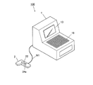
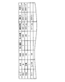
先ず、本発明の実施の形態に係るデータ処理装置100の構成について、図1〜図3を参照ながら説明する。図1は、本発明に係るデータ処理装置100の構成の概略を示す概略図であり、図2は、データ処理装置100の機能的構成を模式的に示すブロック図であり、図3は、PLUファイル171の構成を例示する図である。
First, the configuration of the
図1に示すように、データ処理装置100は、各種情報を表示する表示部13、操作指示を受け付ける操作部18、及び特に図示しないドロアを備えるECR端末1と、特に図示しない読み取り光学系からの情報を表示する表示部22及び当該読み取り光学系から商品識別情報を読み取る指示を受け付けるスキャン開始指示ボタン24aを備えるスキャナ2と、がパラレル/シリアル通信のケーブルである通信ケーブルN1を介して接続する構成であり、例えば販売店における商品の精算場所に設けられ、商取引の決済・記録、金銭の保管、商品管理に関する処理を行なう。
As shown in FIG. 1, the
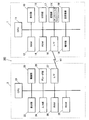
ECR端末1は、図2に示すように、CPU11、RAM12、表示部13、ROM14、印字部15、I/F16、記憶部17、操作部18、及び送受信部19を備え、上記各部が電気的に接続された構成である。
As shown in FIG. 2, the
CPU11は、RAM12の所定領域を作業領域としてROM14や記憶部17に記憶されている各種制御プログラムやデータを元に各種処理を実行し、上記各部に制御信号を送ってECR端末1及びスキャナ2の動作全般を統括制御する。
また、CPU11は、常時一定周波数を発信する水晶発振器(特に図示しない)によるクロック信号を基準に動作するとともに、当該クロック信号を計数して現在時刻を計時する。
The
The
RAM12は、例えばSDRAM(Synchronous Dynamic Random Access Memory)などで構成される揮発性メモリであり、CPU11により実行される各種制御プログラムをプログラム格納エリアに展開する。また、RAM12は、入力データ及び制御処理プログラムの実行時に生じる処理結果のデータを、ワークエリアに一時的に格納する。
The
表示部13は、LCD(Liquid Crystal Display)又はEL(Electro Luminescence)ディスプレイ等であり、CPU11から入力される表示指示に従って各種表示データの画面表示を行う。
The
ROM14は、例えば電気的に消去及び書き換えが可能な不揮発メモリであるEEPROM(Electrically Erasable and Programmable ROM)やフラッシュメモリなどであり、CPU11が読み出して実行する各種プログラム、具体的には、後述する処理プログラムなどを格納する。
The
印字部15は、例えばセグメント単位のサーマル素子がライン状に配列された印字ヘッド部と、セットされたロール状の領収書用紙を前記印字ヘッド部へ送る搬送部とにより構成され(いずれも図示しない)、CPU11から所定の時間間隔で1ライン毎に入力される売上データ及び日付時刻データに基づき、レシート用紙送り及びレシート用紙への印字を行い、印刷されたレシートを排紙する。また、レシートへの印字と同時に、当該レシートに印字した内容と同一内容をジャーナル用紙に印字する。
The printing unit 15 includes, for example, a print head unit in which thermal elements in units of segments are arranged in a line, and a transport unit that sends a set roll-shaped receipt sheet to the print head unit (none of which is shown). ) Based on the sales data and date / time data input for each line from the
I/F16は、通信ケーブルN1を介してシリアル/パラレル通信でスキャナ2と電気的に接続するためのインターフェイスである。具体的には、パラレル通信におけるバス配線を接続する構成や、I2C(登録商標)、UART(Universal Asynchronous Receiver Transmitter)、USB(Universal Serial Bus)、SCL(Serial CLock)、SDA(Serial DAta)などのシリアル通信規格により通信可能に接続する構成である。
The I /
記憶部17は、磁気的又は光学的に読み出し/書き換えが可能なCDROM・DVD・MOなどの記録媒体やフラッシュメモリーなどの半導体メモリであり、予め設定される登録情報であるPLUファイル171を格納する構成である。なお、上述の記録媒体・半導体メモリは、固定的又は着脱可能に装着されるものであって良い。
The
PLUファイル171は、図3に示すように、各商品に対してユニークに設定されたコード(数値化したもの)、品名、単価、売上個数、売上金額、商品を撮影した撮影画像、その撮影を行なった撮影日、及び管理者が当該商品のPLUファイル171への登録を承認した承認日のフィールドを備え、一つの登録情報を一つのレコードで管理するファイルである。なお、PLUファイル171の項目は、さらに商品分類などを有する構成であってよく、特に上記に列挙したものに限定するものではない。
As shown in FIG. 3, the
操作部18は、テンキー/ファンクションキー、モードキー、担当者キー、タッチパネル等を含み(いずれも図示しない)、押下されたキーに対応する押下信号をCPU11に出力する。
The
送受信部19は、LAN(Local Area Network)、インターネット、WAN(Wide Area Network)、電話回線網、無線通信回線、ISDN(Integrated Services Digital Network)回線網、広域通信回線網、専用線、移動体通信網、通信衛星回線、CATV(Cable Television)回線、光通信回線又はそれらを接続するインターネットサービスプロバイダを含む構成などによりデータ通信可能である通信路に接続して、互いに通信可能なサーバなどの他の外部機器との間でデータ通信を行なうインターフェイスである。
The transmission /
スキャナ2は、図2に示すように、CPU21、表示部22、撮像部23、入力部24、デコーダ部25、RAM26、I/F27、及びROM28を備え、上記各部が電気的に接続された構成である。
As shown in FIG. 2, the
CPU21は、前述のCPU11からの制御指示に基づいて、RAM26の所定領域を作業領域としてROM28に記憶されている各種制御プログラムやデータを元に各種制御処理を実行し、スキャナ2の各部に制御信号を送ってスキャナ2の細部における動作を制御する。
Based on the control instruction from the
表示部22は、LCD又はELディスプレイ等であり、CPU21から入力される表示指示に従った表示データを画面表示する。
The
撮像部23は、ガラスやプラスチックなどからなる光学レンズからの光をCCD(Charge Coupled Device)やCMOS(Complementary Metal Oxide Semiconductor)などの撮像素子上に光学像として結像し、その像を電気的な信号としてCPU21に出力する。また、撮像部23は、CPU21の指示に基づいて駆動するアクチュエータにより光学レンズ位置を調整して行なうズーム・焦点調整機能や、CPU21の画像処理によるデジタルズーム機能を備え、商品に貼付された商品識別情報を読み取る通常のモードと(最近接撮影用画角/焦点)、商品の外観を撮影する商品撮影モード(近影撮影用画角/焦点)とを調整可能な構成である(いずれも図示しない)。
The
また、撮像部23は、レーザスキャナなど専ら商品に貼付され商品識別情報を読み取る構成を有し、上記通常モードにおいてはレーザスキャナによる読み取りを行ない、撮影モードにおいては撮像素子上の光学像を読み取るような、切り替えて使用する構成であっても良い。
The
なお、商品に貼付された商品識別情報とは、前述の商品毎にユニークに設定されたコード、数字、文字列などである。コードの具体的な例としては、JANコード、UPCコード、CDDE39等の一次元バーコードや、カラーバーコード、又はQRコード(登録商標)、PDF417、Data Matrix、Maxi Code等の二次元コードがある。 The product identification information affixed to the product is a code, number, character string, or the like uniquely set for each product described above. Specific examples of codes include one-dimensional barcodes such as JAN code, UPC code, and CDDE39, and two-dimensional codes such as color barcode, QR code (registered trademark), PDF417, Data Matrix, and Maxi Code. .
入力部24は、撮像部23への撮影開始を指示するスキャン開始指示ボタン24aを含む操作ボタンにより構成され、ボタン押下時の押下信号をCPU21に出力する。
The
デコーダ部25は、画像認識用DSP(Digital Signal Processor)などを有し、CPU21からの指示により、撮像部23で撮像された画像データからコード(商品識別情報)の部分を抽出して数値化する。また、デコーダ部25は、OCR(Optical Character Reader)としての機能により、文字列又は数字の画像データを数字/文字データとして認識する構成であっても良い。
The
RAM26は、SDRAMなどで構成される揮発性メモリであり、撮像部23で撮像された画像の一時保存領域やデコーダ部25におけるコード解析時の作業領域を提供する。
I/F27は、通信ケーブルN1を介して上述したI/F16と通信可能に接続するインターフェイスである。
ROM28は、EEPROMやフラッシュメモリーなどであり、CPU21が読み出して処理する制御プログラムやデータを格納する。
The
The I /
The
上記構成により、スキャナ2は、特に別のコマンドが割り当てられていない通常である場合のスキャン開始指示ボタン24aの押下により、その押下信号を受信したタイミングで、撮像部23で撮像した画像データに基づいて商品コード(商品識別情報)を解析して数値化する。そして、スキャナ2は、数値化した商品コード(商品識別情報)をECR端末1に送信する。
With the above-described configuration, the
なお、スキャナ2は、通信ケーブルN1によりECR端末1と接続するハンディスキャナであるが、特に図示しない精算台に固設される構成であっても良い。好適な構成は、商品コードの読み取りと商品画像の撮影とを容易に行なうことが可能なハンディスキャナの構成である。
The
また、ECR端末1とスキャナ2との接続は、有線に限定するものではなく、例えばGSM(Global System for Mobile communication)方式、GPRS(General Packet Radio System ;汎用パケット無線システム)方式、PDC(Personal Digital Cellular)方式、CDMA(Code Division Multiple Access)方式、PHS(Personal Handyphone System)方式、Bluetooth無線通信方式、無線LAN(Local Area Network)等による無線通信や、IrDA(Infrared Data Association)、IrMC(Infrared Mobile Communications)等による赤外線通信であっても良い。さらに、ECR端末1に対して複数のスキャナ2を備える構成であっても良い。
The connection between the
次に、データ処理装置100のCPU11が行なう処理について、図4を参照して説明する。図4は、CPU11が行なうNPFメンテナンス処理を含む会計処理(ステップS11〜S27)を説明するフローチャートである。
Next, processing performed by the
先ず、CPU11は、撮像部23から会計を行なう商品に貼付された商品コード(商品識別情報)をスキャンして(ステップS11)、当該商品コードに基づいたPLUファイル171の検索を行ない(ステップS12)、該当するレコードがPLUファイル171の「コード」のフィールドにあるか否かの判定を行なう(ステップS13)。
First, the
ステップS13において、スキャンされた商品コードに該当するレコードがある場合は、当該レコードにおける単価と、操作部18から入力される売上個数と、に基づいた支払金額の算出が行なわれ、金銭授受などの会計手続の確認後における操作部18の確定キー押下によりPLUファイル171の売上個数と売上金額が加算される、単価に基づく売上合計処理が行なわれ(ステップS14)、終了する。
In step S13, if there is a record corresponding to the scanned product code, the amount of payment is calculated based on the unit price in the record and the number of sales input from the
ステップS13において、スキャンされた商品コードに該当するレコードがない場合は、ステップS15〜S27に示すNPFメンテナンス処理が行なわれた後に、単価に基づく売上合計処理が行なわれて(ステップS14)、終了する。 In step S13, if there is no record corresponding to the scanned product code, after the NPF maintenance process shown in steps S15 to S27 is performed, the sales total process based on the unit price is performed (step S14), and the process ends. .
以下に、NPFメンテナンス処理について詳細に説明する。NPFメンテナンス処理が開始されると、商品画像を撮像部23から撮影するガイダンスが表示部13に表示され(ステップS15)、スキャン開始指示ボタン24aの押下に対してRAM26への画像の取り込みである撮影開始を指示するコマンドが設定され(ステップS16)、撮像部23が商品の外観を撮影する商品撮影モードへ設定される(ステップS17)。
The NPF maintenance process will be described in detail below. When the NPF maintenance process is started, guidance for photographing a product image from the
ステップS17の後、表示制御手段としてのステップS18により、撮像された画像がそのまま確認用のスルー画像として表示部22に表示され、スキャン開始指示ボタン24aの押下による撮影開始指示があるまで待機される(ステップS19)。
After step S17, in step S18 as a display control means, the captured image is displayed as it is on the
撮影開始指示が確認されると(ステップS19:Y)、撮像された画像データが商品画像データとしてRAM26に格納され(ステップS20)、操作部18から商品名の入力が受け付けられ(ステップS21)、確認手段としてのステップS22により、表示部13又は表示部22に撮像した商品画像データと入力した「商品名」が表示されて登録の確認が行なわれ、やり直しの指示が入力された場合はステップS18へ戻る。
When the shooting start instruction is confirmed (step S19: Y), the captured image data is stored as product image data in the RAM 26 (step S20), and an input of a product name is accepted from the operation unit 18 (step S21). In step S22 as confirmation means, the product image data imaged on the
ステップS22において登録が確認されると、撮像部23の商品撮影モードが解除されて通常のモードに移行され(ステップS23)、ステップS16で設定されたスキャン開始指示ボタン24aのコマンドが解除されて通常の状態へ戻される(ステップS24)。
When registration is confirmed in step S22, the product photographing mode of the
ステップS24の後、ステップS11でスキャンされた商品コード、ステップS22で確認された商品名と商品画像データ、及び当該商品画像データを撮像した日時がPLUファイル171の新規レコードにおける「コード」・「品名」・「撮影画像」・「撮影日」のフィールドに格納され(ステップS25)、操作部18から商品単価の入力が受け付けられ(ステップS26)、当該商品単価の確認が行なわれた後(ステップS27)、NPFメンテナンス処理が終了してステップS14へ移行する。
After step S24, the product code scanned in step S11, the product name and product image data confirmed in step S22, and the date and time when the product image data was captured are “code” and “product name” in the new record of the
上記構成により、データ処理装置100は、CPU11において実行される会計処理において、会計を行なう商品の商品識別情報である商品コードをスキャナ2で読み取り、数値化された当該商品コードを元にPLUファイル171を参照して得られる単価と、操作部18から入力される売上個数と、に基づいて支払金額の算出を行い、金銭授受の確認後の操作部18における確定キーの押下により、PLUファイル171の売上個数と売上金額を加算する、単価に基づく売上合計処理を行なう。
With the above configuration, in the accounting process executed by the
また、データ処理装置100は、スキャナ2で読み取られた商品コードがPLUファイル171に登録されていない場合には、当該商品コードに対してスキャナ2で撮像した商品画像と操作部18から入力された単価を設定してPLUファイル171に登録するNPFメンテナンス処理を行なう。このため、会計を行なう商品が未登録であると判明した場合に、その場で商品登録情報の追加登録を行なうことができると同時に、登録した商品登録情報の確認時に商品画像も確認することを可能とする、より確実な商品登録情報の追加登録を行なうことができる。
Further, when the product code read by the
[第2の実施の形態]
次に、図5〜図7を参照して、第2の実施の形態に係るデータ処理システム101について説明する。図5は、データ処理システム101の構成の概略を示す概略図であり、図6は、データ処理システム101の機能的構成を模式的に示すブロック図であり、図7は、データ処理システム101の会計処理を説明するラダーチャートである。なお、簡略化のため、データ処理装置100と同様の構成については、同一の符号を付して説明を省略し、データ処理装置100と異なるサーバ3を備えた構成についてのみ説明する。
[Second Embodiment]
Next, a
データ処理システム101は、図5に示すように、前述のデータ処理装置100にECR端末1と通信ケーブルN2により互いに通信可能に接続するサーバ3を加えた構成である。サーバ3は、統括的にPOS処理を行なうためにPLUファイル171の元となるデータを管理し、例えば営業開始時にECR端末1に対してPLUファイル171を更新するためのデータの送信などを行なう。また、サーバ3は、複数のECR端末1を管理する構成であってもよい。
As shown in FIG. 5, the
具体的には、サーバ3は、図6に示すように、CPU31、RAM32、表示部33、ROM34、印字部35、送受信部36、記憶部37、及び操作部38を備え、上記各部が電気的に接続された構成である。
Specifically, as shown in FIG. 6, the
CPU31は、RAM32の所定領域を作業領域としてROM34や記憶部37に記憶されている各種制御プログラムやデータを元に各種処理を実行し、上記各部に制御信号を送ってサーバ3の動作全般を統括制御する。
The
具体的には、CPU31は、入力される画像データを二値化して当該画像データに含まれる文字の輪郭を抽出し、予めROM34に格納される文字の形状データと比較することによる文字認識を行なう。
また、CPU31は、操作部38によるPLUマスタファイル371の編集制御の他、送受信部36から送られるデータに基づいたPLUマスタファイル371の追加・更新を行なう。
Specifically, the
In addition to the editing control of the
RAM32は、SDRAMなどで構成される揮発性メモリであり、CPU31で実行される各種制御プログラムをプログラム格納エリアに展開する。また、RAM32は、入力データ及び制御処理プログラムの実行時に生じる処理結果のデータを、ワークエリアに一時的に格納する。
The
表示部33は、LCD、CRT(Cathode-Ray Tube)ディスプレイ等であり、CPU31から入力される表示指示に従って各種表示データの画面表示を行なう。
The display unit 33 is an LCD, a CRT (Cathode-Ray Tube) display, or the like, and performs screen display of various display data in accordance with a display instruction input from the
ROM34は、電気的に消去及び書き換えが可能な不揮発メモリであるEEPROMやフラッシュメモリなどであり、CPU31が読み出して実行する各種プログラムを格納する。
The
印字部35は、電子写真方式、インクジェット方式、熱転写方式等の画像形成方法によって、紙等の記録媒体に画像を形成して出力する装置である。
The
送受信部36は、前述の送受信部19と同様な構成であり、通信路である通信ケーブルN2を介してECR端末1と電気的に接続するインターフェイスである。
The transmission /
記憶部37は、磁気的又は光学的に読み出し/書き換えが可能なCDROM・DVD・MOなどの記録媒体やフラッシュメモリーなどの半導体メモリであり、PLUファイル171の元であるPLUマスタファイル371を格納する構成である。なお、PLUマスタファイル371は、PLUファイル171と同様なフィールド構成であり、一つの商品登録情報(登録情報)を一つのレコードで管理するファイルである。
The
操作部38は、数字キー、文字キー、各種機能キー等から構成されるキーボードや、マウス、タッチパネル等のポインティングデバイスを含んで構成され、サーバ3への操作指示を受け付ける。
The
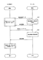
次に、データ処理システム101における会計処理であり、前述のデータ処理装置100におけるNPFメンテナンス処理を含む会計処理にサーバ3による当該NPFメンテナンス処理に対する認証処理を含む流れについて、図7に示すラダーチャートを参照して説明する。
なお、図7に示す処理においては、ECR端末1側の処理はCPU11が制御して行い、サーバ3側の処理はCPU31が制御して行なう。また、サーバ3との処理で具体的に関係しない前述のデータ処理装置100における各処理の細部は省略して示す。
Next, a ladder chart shown in FIG. 7 is shown for the accounting process in the
In the process shown in FIG. 7, the
先ず、ECR端末1は、NFPメンテナンス処理におけるステップS21で、操作部18からの商品名の入力の代わりに商品に貼付されている商品名が記載されたラベルなどを撮像した商品画像データをサーバ3に出力する。サーバ3は、受信した商品画像データに基づいて文字認識を行ない、認識された文字列を品名情報としてECR端末1に送信する(ステップS31)。この品名情報を受信したECR端末1は、図7のステップS22で表示され、ステップS25で前記受信した品名情報をPLUファイル171の品名として品名情報を設定する。
First, in step S21 in the NFP maintenance process, the
上記ステップS31の処理により、データ処理システム101においては、ECR端末1で品名を入力する手間を省くことができるとともに、正確に品名がPLUファイル171に登録されているか否かをチェックすることが可能となる。
By the processing in step S31, the
ECR端末1は、NPFメンテナンス処理(ステップS15〜S27)が終了した後、上記処理によりPLUファイル171に追加した新規レコードデータをサーバ3に送信する。サーバ3は、送られてきた新規レコードデータに基づいたPLUマスタファイル371の更新認証処理として、当該新規レコードデータを表示部33に表示し、管理者による更新するか否かの選択入力を操作部38から受け付け(ステップS32)、更新された後にPLUマスタファイル371の更新を示す情報、つまりPLUファイル171への本登録を示す認証情報をECR端末1に対して送信する。
After completing the NPF maintenance process (steps S15 to S27), the
なお、ステップS32における処理は、操作部38による操作指示以外に、受信した新規レコードデータの商品名と単価、及びROM34又は記憶部37に格納された商品名と商品のカテゴリと当該カテゴリにおける価格帯とによるルックアップテーブルである適正価格情報に基づき、送られてきた新規レコードデータにおける商品の単価が適正な価格帯に含まれるか否かを判定する構成であっても良い。
In addition to the operation instruction by the
ECR端末1では、認証情報の受信に応じて新規登録したPLUファイル171のレコードの認証日に現在日時を入力して本登録を行ない、当該本登録された商品登録情報を元に単価に基づく売上合計処理を行なう(ステップS14)。
The
上記構成により、データ処理システム101は、NPFメンテナンス処理時にスキャナ2で撮像した商品画像から品名を入力することできるため、より簡易な商品登録を行なうことができる。また、データ処理システム101は、ECR端末1で新規に追加される商品登録情報に対してサーバ3側で承認を行なう構成であるため、より確実に商品登録を行なうことができるとともに、PLUマスタファイル371により登録する商品登録情報を一元管理することができる。このため、例えば新たにECR端末1を追加する場合においても、PLUマスタファイル371を元に設定することで、新規に追加するECR端末1に対して最新の商品登録情報を登録することができる。なお、サーバ3で商品画像データに基づく文字認識を行うようにしたが、ECR端末1側で文字認識を行い、その文字列を品名情報としてPLUファイル171に設定するようにしてもよい。
With the above configuration, the
なお、本実施の形態における記述は、本発明の一例を示すものであり、これに限定しない。本実施の形態におけるデータ処理装置100、データ処理システム101の細部構成及び細部動作に関しては、本発明の趣旨を逸脱しない範囲で適宜変更が可能である。
Note that the description in the present embodiment shows an example of the present invention, and the present invention is not limited to this. The detailed configuration and detailed operation of the
例えば、本実施の形態におけるスルー画像の表示は、表示部22の表示画面に表示する構成としたが、表示部13であっても良く、特に限定しない。
また、入力されたデータに基づいて音声データの合成を行なう音声合成装置と入力される音声データから音声を再生するスピーカとによる音声再生手段をさらに有し、確認手段は、記録されるデータを音声再生手段による音声で行なう構成であっても良い。
For example, the through image display in the present embodiment is configured to be displayed on the display screen of the
Further, the apparatus further includes a voice reproduction means using a voice synthesizer that synthesizes voice data based on the input data and a speaker that reproduces voice from the input voice data, and the confirmation means converts the recorded data into voice A configuration in which the sound is played by a reproducing unit may be used.
100 データ処理装置
101 データ処理システム
N1、N2 通信ケーブル
1 ECR端末
11 CPU(判定手段)
12 RAM
13 表示部
14 ROM
15 印字部
16 I/F
17 記憶部(記憶手段、記録手段)
171 PLUファイル
18 操作部(単価設定手段)
19 送受信部
2 スキャナ(商品識別情報読み取り手段、撮像手段)
21 CPU
22 表示部(表示手段)
23 撮像部
24 入力部
24a スキャン開始指示ボタン
25 デコーダ部
26 RAM
27 I/F
28 ROM
3 サーバ
31 CPU
32 RAM
33 表示部
34 ROM
35 印字部
36 送受信部
37 記憶部
371 PLUマスタファイル
38 操作部
DESCRIPTION OF
12 RAM
13
15 Printing section 16 I / F
17 Storage unit (storage means, recording means)
171
19 Transmission /
21 CPU
22 Display section (display means)
23
27 I / F
28 ROM
3
32 RAM
33
35
Claims (4)
各商品に付された前記商品識別情報を読み取る商品識別情報読み取り手段と、
前記読み取られた商品識別情報が前記登録情報に含まれているか否かを判定する判定手段と、
前記判定の結果、前記読み取られた商品識別情報が前記登録情報に含まれていない場合に、前記商品識別情報が付された商品を撮像する撮像手段と、
前記登録情報に前記読み取られた商品識別情報と前記撮像された商品画像とを対応づけて記録する記録手段と、
を備えたことを特徴とするデータ処理装置。 Storage means for storing registration information in which product identification information for identifying each product is associated with a product price corresponding to the product identification information;
Product identification information reading means for reading the product identification information attached to each product;
Determination means for determining whether or not the read product identification information is included in the registration information;
As a result of the determination, when the read product identification information is not included in the registration information, an imaging unit that images the product with the product identification information;
Recording means for associating and recording the read product identification information and the captured product image with the registration information;
A data processing apparatus comprising:
前記記録手段は、前記登録情報に前記読み取られた商品識別情報と前記撮像された商品画像と前記単価とを対応づけて記録することを特徴とする請求項1に記載のデータ処理装置。 Unit price setting means for setting a unit price corresponding to the read product identification information;
The data processing apparatus according to claim 1, wherein the recording unit records the read product identification information, the captured product image, and the unit price in association with the registration information.
各商品を識別する商品識別情報と当該商品識別情報に対応する商品価格とが対応づけられた登録情報を格納する記憶手段、
前記読み取られた商品識別情報が前記登録情報に含まれているか否かを判定する判定手段、
前記判定の結果、前記読み取られた商品識別情報が前記登録情報に含まれていない場合に、前記撮像手段により当該商品識別情報が付された商品の画像を取得する商品画像取得手段、
前記登録情報に前記読み取られた商品識別情報と前記商品画像とを対応づけて記録する記録手段、
として機能させるためのプログラム。 A computer having product identification information reading means for reading product identification information attached to each product and imaging means for imaging the product,
Storage means for storing registration information in which product identification information for identifying each product is associated with a product price corresponding to the product identification information;
Determination means for determining whether or not the read product identification information is included in the registration information;
As a result of the determination, when the read product identification information is not included in the registration information, a product image acquisition unit that acquires an image of a product to which the product identification information is attached by the imaging unit;
Recording means for recording the read product identification information and the product image in association with the registration information;
Program to function as.
Priority Applications (1)
| Application Number | Priority Date | Filing Date | Title |
|---|---|---|---|
| JP2005093928A JP2006277198A (en) | 2005-03-29 | 2005-03-29 | Data processor and program |
Applications Claiming Priority (1)
| Application Number | Priority Date | Filing Date | Title |
|---|---|---|---|
| JP2005093928A JP2006277198A (en) | 2005-03-29 | 2005-03-29 | Data processor and program |
Publications (2)
| Publication Number | Publication Date |
|---|---|
| JP2006277198A true JP2006277198A (en) | 2006-10-12 |
| JP2006277198A5 JP2006277198A5 (en) | 2008-01-10 |
Family
ID=37211916
Family Applications (1)
| Application Number | Title | Priority Date | Filing Date |
|---|---|---|---|
| JP2005093928A Pending JP2006277198A (en) | 2005-03-29 | 2005-03-29 | Data processor and program |
Country Status (1)
| Country | Link |
|---|---|
| JP (1) | JP2006277198A (en) |
Cited By (11)
| Publication number | Priority date | Publication date | Assignee | Title |
|---|---|---|---|---|
| US7913909B2 (en) | 2008-01-24 | 2011-03-29 | Toshiba Tec Kabushiki Kaisha | Point of sale datacode reading apparatus and real-time display |
| JP2012038215A (en) * | 2010-08-10 | 2012-02-23 | Toshiba Tec Corp | Code reader and program |
| JP2012053710A (en) * | 2010-09-01 | 2012-03-15 | Toshiba Tec Corp | Store system, sales registration device and program |
| JP2012059249A (en) * | 2010-08-10 | 2012-03-22 | Toshiba Tec Corp | Code reading device and program |
| JP2012247968A (en) * | 2011-05-27 | 2012-12-13 | Toshiba Tec Corp | Information processor, information processing method and control program |
| US8458036B2 (en) | 2008-01-24 | 2013-06-04 | Toshiba Tec Kabushiki Kaisha | Datacode reading apparatus |
| JP2015035094A (en) * | 2013-08-08 | 2015-02-19 | 東芝テック株式会社 | Information processing apparatus, shop system, and program |
| JP2015138285A (en) * | 2014-01-20 | 2015-07-30 | ブラザー工業株式会社 | printer |
| US10740743B2 (en) | 2012-08-03 | 2020-08-11 | Nec Corporation | Information processing device and screen setting method |
| JP2020160930A (en) * | 2019-03-27 | 2020-10-01 | 株式会社寺岡精工 | Commodity selling data processing device and program |
| CN111768261A (en) * | 2019-10-14 | 2020-10-13 | 北京京东尚科信息技术有限公司 | Display information determining method, device, equipment and medium |
Citations (4)
| Publication number | Priority date | Publication date | Assignee | Title |
|---|---|---|---|---|
| JPS62287399A (en) * | 1986-06-05 | 1987-12-14 | 富士通株式会社 | Registration system for unregistered goods of pos system |
| JPH02150960A (en) * | 1988-12-02 | 1990-06-11 | Hitachi Ltd | Stock control system for big store |
| JPH0628575A (en) * | 1992-07-10 | 1994-02-04 | Omron Corp | Merchandise register system |
| JP2004252599A (en) * | 2003-02-18 | 2004-09-09 | Seiko Epson Corp | Image reader system, recording medium, image reading device and image processing method for pos terminal |
-
2005
- 2005-03-29 JP JP2005093928A patent/JP2006277198A/en active Pending
Patent Citations (4)
| Publication number | Priority date | Publication date | Assignee | Title |
|---|---|---|---|---|
| JPS62287399A (en) * | 1986-06-05 | 1987-12-14 | 富士通株式会社 | Registration system for unregistered goods of pos system |
| JPH02150960A (en) * | 1988-12-02 | 1990-06-11 | Hitachi Ltd | Stock control system for big store |
| JPH0628575A (en) * | 1992-07-10 | 1994-02-04 | Omron Corp | Merchandise register system |
| JP2004252599A (en) * | 2003-02-18 | 2004-09-09 | Seiko Epson Corp | Image reader system, recording medium, image reading device and image processing method for pos terminal |
Cited By (15)
| Publication number | Priority date | Publication date | Assignee | Title |
|---|---|---|---|---|
| US8458036B2 (en) | 2008-01-24 | 2013-06-04 | Toshiba Tec Kabushiki Kaisha | Datacode reading apparatus |
| US8132730B2 (en) | 2008-01-24 | 2012-03-13 | Toshiba Tec Kabushiki Kaisha | Datacode reading apparatus |
| US7913909B2 (en) | 2008-01-24 | 2011-03-29 | Toshiba Tec Kabushiki Kaisha | Point of sale datacode reading apparatus and real-time display |
| JP2012038215A (en) * | 2010-08-10 | 2012-02-23 | Toshiba Tec Corp | Code reader and program |
| JP2012059249A (en) * | 2010-08-10 | 2012-03-22 | Toshiba Tec Corp | Code reading device and program |
| JP2012053710A (en) * | 2010-09-01 | 2012-03-15 | Toshiba Tec Corp | Store system, sales registration device and program |
| JP2012247968A (en) * | 2011-05-27 | 2012-12-13 | Toshiba Tec Corp | Information processor, information processing method and control program |
| US8584962B2 (en) | 2011-05-27 | 2013-11-19 | Toshiba Tec Kabushiki Kaisha | Information processing apparatus and information processing method |
| US10740743B2 (en) | 2012-08-03 | 2020-08-11 | Nec Corporation | Information processing device and screen setting method |
| JP2015035094A (en) * | 2013-08-08 | 2015-02-19 | 東芝テック株式会社 | Information processing apparatus, shop system, and program |
| JP2015138285A (en) * | 2014-01-20 | 2015-07-30 | ブラザー工業株式会社 | printer |
| JP2020160930A (en) * | 2019-03-27 | 2020-10-01 | 株式会社寺岡精工 | Commodity selling data processing device and program |
| JP7311880B2 (en) | 2019-03-27 | 2023-07-20 | 株式会社寺岡精工 | Merchandise sales data processor and program |
| CN111768261A (en) * | 2019-10-14 | 2020-10-13 | 北京京东尚科信息技术有限公司 | Display information determining method, device, equipment and medium |
| CN111768261B (en) * | 2019-10-14 | 2024-03-08 | 北京京东尚科信息技术有限公司 | Display information determining method, device, equipment and medium |
Similar Documents
| Publication | Publication Date | Title |
|---|---|---|
| JP2006277198A (en) | Data processor and program | |
| US10803438B2 (en) | Reading apparatus | |
| US8424761B2 (en) | Commodity code reading apparatus and commodity code reading method | |
| JP2008003859A (en) | Merchandise data processor, settlement device and pos system | |
| JP2014038561A (en) | Information processor, information processing method, and program | |
| US20110010256A1 (en) | Commodity sales system, handy terminal, and method of controlling the handy terminal | |
| JP2011221585A (en) | Code reader, sale registration device and program | |
| JP2007034549A (en) | Proposal design management system | |
| JP2015082256A (en) | Shopping support apparatus and program | |
| JP4312642B2 (en) | Wireless LAN transmitter and control method thereof | |
| JP2008021226A (en) | Sales data processing device and program | |
| KR100847380B1 (en) | Apparatus and method for providing contents by using machine-readable code | |
| EP2905736A1 (en) | Reading apparatus | |
| JP5372099B2 (en) | Commodity data processing device, settlement device and POS system | |
| US20210056558A1 (en) | Checkout system, checkout method, and checkout apparatus | |
| US11315097B2 (en) | Store system | |
| JP2005124176A (en) | Automatic photographing system | |
| KR20040081890A (en) | An Apparatus For Providing Web Shopping Using Code Pattern And Method Thereof | |
| EP2993635A1 (en) | Receipt printing apparatus | |
| JP5231296B2 (en) | Product data input device | |
| JP2006293540A (en) | Sales information management system and method | |
| US11481752B2 (en) | Commodity purchase system and relay server | |
| JP2002215966A (en) | Electronic commerce system, information processor and information processing method | |
| JP2005135000A (en) | Household account book input support system, personal digital assistant, server, and method and program for supporting household account book input | |
| JP7284369B2 (en) | Information processing device, its control method, and program |
Legal Events
| Date | Code | Title | Description |
|---|---|---|---|
| A521 | Request for written amendment filed |
Free format text: JAPANESE INTERMEDIATE CODE: A523 Effective date: 20071115 |
|
| A621 | Written request for application examination |
Free format text: JAPANESE INTERMEDIATE CODE: A621 Effective date: 20071115 |
|
| A977 | Report on retrieval |
Free format text: JAPANESE INTERMEDIATE CODE: A971007 Effective date: 20100127 |
|
| A131 | Notification of reasons for refusal |
Free format text: JAPANESE INTERMEDIATE CODE: A131 Effective date: 20100202 |
|
| A521 | Request for written amendment filed |
Free format text: JAPANESE INTERMEDIATE CODE: A523 Effective date: 20100401 |
|
| A02 | Decision of refusal |
Free format text: JAPANESE INTERMEDIATE CODE: A02 Effective date: 20100629 |