JP2006189221A - Humidifier - Google Patents
Humidifier Download PDFInfo
- Publication number
- JP2006189221A JP2006189221A JP2005002682A JP2005002682A JP2006189221A JP 2006189221 A JP2006189221 A JP 2006189221A JP 2005002682 A JP2005002682 A JP 2005002682A JP 2005002682 A JP2005002682 A JP 2005002682A JP 2006189221 A JP2006189221 A JP 2006189221A
- Authority
- JP
- Japan
- Prior art keywords
- water
- steam
- air
- main body
- humidifier
- Prior art date
- Legal status (The legal status is an assumption and is not a legal conclusion. Google has not performed a legal analysis and makes no representation as to the accuracy of the status listed.)
- Granted
Links
Images


Landscapes
- Air Humidification (AREA)
Abstract
Description
本発明は、加熱により水を蒸気化する加湿器に係り、特に、転倒時の熱湯流出防止の構造を有する加湿器に関する。 The present invention relates to a humidifier that evaporates water by heating, and more particularly, to a humidifier having a structure for preventing hot water outflow during a fall.
従来の加熱式の加湿器においては、蒸気を外部に放出する吹出し口、および蒸気と空気を混合する混合室に空気を取り入れる空気通路をそれぞれ開閉する弁を設け、これら弁は通常運転時に本体が設置面にあるときは弁棒が突き上げられることにより開弁しており、転倒時には本体が設置面から離れることにより閉弁することで、本体転倒時の熱湯流出での火傷安全策とする構成になっている。(例えば、特許文献1参照) A conventional heating humidifier is provided with a blow-off port that discharges steam to the outside, and a valve that opens and closes an air passage for taking in air into a mixing chamber that mixes steam and air. When it is on the installation surface, it is opened by pushing up the valve stem, and when it falls, it closes when the main body moves away from the installation surface, making it a safeguard against burns due to hot water outflow when the main body falls It has become. (For example, see Patent Document 1)
しかしながら、上記従来の加湿器の場合、加湿器の本体が水タンク側に転倒した際には、本体が傾いて行くときに蒸発皿内の熱湯が給水口を通り水受部側へ逆流し、本体外へ流出する恐れがあった。 However, in the case of the conventional humidifier, when the main body of the humidifier falls to the water tank side, when the main body tilts, the hot water in the evaporating dish flows backward through the water supply port to the water receiving portion side, There was a risk of spilling out of the body.
本発明は、上記問題点を解消するためになされたもので、本体転倒時に熱湯の流出を防止できる加湿器を提供することを目的とする。 The present invention has been made to solve the above-described problems, and an object of the present invention is to provide a humidifier that can prevent hot water from flowing out when the main body falls.
本発明に係る加湿器は、吸気口を有する本体、この本体内に設けられた水タンク、この水タンクからの水を受ける水受部、この水受部の給水口を介して供給された水を加熱する蒸発皿、この蒸発皿内から発生する蒸気を案内する蒸気案内筒、前記吸気口から空気を取り込む送風ファン、この送風ファンから送られる空気を案内する空気案内筒、前記蒸気案内筒からの蒸気と前記空気案内筒からの空気を混合させる混合室及びこの混合室からの蒸気を外部に放出する吹出口を備えた加湿器において、前記水受部の前記給水口に、通常運転時には開き、前記本体の転倒時には閉じる逆止弁機構を備えたものである。 The humidifier according to the present invention includes a main body having an air inlet, a water tank provided in the main body, a water receiving portion for receiving water from the water tank, and water supplied via a water supply port of the water receiving portion. An evaporating dish for heating the evaporating dish, a steam guiding cylinder for guiding steam generated from the evaporating dish, a blower fan for taking in air from the intake port, an air guiding cylinder for guiding air sent from the blowing fan, and the steam guiding cylinder In a humidifier equipped with a mixing chamber for mixing steam from the air guide tube and an air outlet for discharging the steam from the mixing chamber to the outside, the water inlet of the water receiving portion is opened during normal operation. A check valve mechanism that closes when the main body falls is provided.
本発明によれば、水受部の前記給水口に、通常運転時には開き、前記本体の転倒時には閉じる逆止弁機構を備えたので、転倒時の機体外への熱湯の流出を防ぐことができる。 According to the present invention, the water supply port of the water receiving portion is provided with a check valve mechanism that opens during normal operation and closes when the main body falls, so that hot water can be prevented from flowing out of the machine body during the fall. .
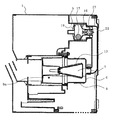
図1は本発明による実施の形態を示す加湿器の断面図、図2は加湿器の水受部の拡大図である。加湿器は、合成樹脂で成形され側面に吸気口10を設けた本体1内に、水タンク2が設けられ、水タンク2に落水口4とこの落水口4を開閉する止水弁30を有するタンクキャップ3が取り付けられている。また、水タンク2内から落水口4を通って供給され、タンクキャップ3により一定水位に保持される水を受け、給水口27を有する水受部5が設けられている。
FIG. 1 is a cross-sectional view of a humidifier showing an embodiment of the present invention, and FIG. 2 is an enlarged view of a water receiver of the humidifier. The humidifier is provided with a
水受部5の下部には、図2に示すように、逆止弁機構16が設けられている。
逆止弁機構16は、上部に広口部18aを有し、側面の導入口18b、下部に狭口部が設けられた断面略漏斗状の保持体である球体保持体18と、球体保持体18の広口部29に、上面に水タンク2に取り付けられたタンクキャップ3の止水弁30を押し上げる突起19aを有するフタ19と、球体保持体18の狭口部内に設けられたリブ状の座受部20に上下可動に支持されたバルブシャフト21と、このバルブシャフト21の下端に設けられ給水口27を開閉する逆止弁22と、バルブシャフト21の上端に設けられた円板23と座受部20との間に設けられ逆止弁22を常時上方に付勢するコイルバネ24と、通常はバルブシャフト21の円板23に載置され、逆止弁22を自重により下方に押圧して、給水口27を開とするステンレスで形成された球体17から構成されている。なお、バルブシャフト21、逆止弁22及び円板23で弁部を構成する。
As shown in FIG. 2, a
The
また、水受部5の逆止弁機構16の給水口27に、ゴムホース26を介して接続され、水受部5から供給された水を加熱体8の加熱により水蒸気を発生させる蒸発皿6が設けられ、蒸発皿6上方には水蒸気を上方に案内する蒸気案内筒9が設けられている。
また、蒸気案内筒9の下には、蒸発皿6の湯量を減らすための耐熱水性樹脂で成形された円錐台形状の湯量低減部材7が設けられており、結果として蒸発皿6内に湯量低減部材7が介在することになる。
また、蒸気案内筒9には低減された湯量を万が一本体が転倒した際に収容できる容積の湯溜め部9aが設けられ、湯量低減部材7の外周には、湯量低減部材7の形状に倣った形状の蒸発残渣吸着体13が配設されている。
The evaporating
Also, under the
The
蒸気案内筒9の上部には、吸気口10から送風ファン11により取り込まれ、送出された空気を案内する空気案内筒12が設けられ、また、蒸気案内筒9から送られてきた蒸気と空気案内筒12より送られる送風を混合させる混合室14と、混合室14からの蒸気を外部に放出する吹出口15が設けられている。
An
次に、上記の構成からなる実施の形態の動作について説明する。
水タンク2を本体1にセットすると、水タンク2内の水はタンクキャップ3に備えられている落水口4を通って水受部5に供給されタンクキャップ3により一定水位に保持される。水受部5の下部の逆止弁機構16は、通常運転時には、球体17の自重により逆止弁22が開かれ、水受部5の水は給水口27、ゴムホース26を通って蒸発皿6へ水が供給される。
Next, the operation of the embodiment configured as described above will be described.
When the
蒸発皿6内の水位は水受部5と同水位で、蒸発皿6底面より50〜60mmの高さに保持される。そして、蒸発皿6内には湯量低減部材7があるため、蒸発皿6内の湯量は湯量低減部材7がない場合に比べ絶対量を減らすことができる。
また、湯量低減部材7の外周に設けられた蒸発残渣吸着体13により、蒸発皿6内の水を蒸発させることにより発生する蒸発残渣は蒸発残渣吸着体13に吸着される。
The water level in the evaporating
Further, the evaporation
蒸発皿6内の水が加熱体8により加熱されて発生した水蒸気は、蒸気案内筒9により上方に案内される。一方、吸気口10からの空気が送風ファン11により蒸気案内筒9の上部の空気案内筒12に案内されている。そして、混合室14内で、空気案内筒12に案内された空気と蒸気案内筒9により上方に案内された蒸気が混合され、吹出口15から外部に放出される。
The water vapor generated when the water in the evaporating
次に、加湿器を水タンク2側に転倒させた場合の動作につき図3、図4により説明する。
図3は実施の形態の加湿器を水タンク2側に転倒させた場合の水受け部分の断面図、 図4は加湿器を水タンク2側に転倒させた場合の蒸発皿部分の断面図である。
図3に示すように、転倒した際には水受部5の逆止弁機構16のバルブシャフト21の円板23から球体17が外れるので、コイルバネ24で押圧された逆止弁22により、給水口27が閉じられ、蒸発皿6から給水口27を通って水受部5へ熱湯が逆流し、水受部5から熱湯が流出することがない。
また、図4に示すように、転倒した際に蒸発皿6内の湯は必ず蒸気案内筒9に設けられた湯溜め部9aに流れ込むようになっており、30℃に近い温度の熱湯がそのまま機体外へ流出することがない。
Next, the operation when the humidifier is turned over to the
3 is a cross-sectional view of the water receiving portion when the humidifier of the embodiment is turned over to the
As shown in FIG. 3, since the
Also, as shown in FIG. 4, hot water in the evaporating
次に、加湿器を蒸発皿6側に転倒させた場合の動作につき図5により説明する。
図5は実施の形態の加湿器を蒸発皿6側に転倒させた場合の断面図である。
図5に示すように、転倒した際には水受部5の逆止弁機構16のバルブシャフト21の円板23から球体17が外れるので、コイルバネ24で押圧された逆止弁22により、給水口27が閉じられ、水受部5から給水口27を通って蒸発皿6へ水が流れるのを防止し、水受部5からの水が湯溜め部9aの熱湯に混ざり、湯量が増えることを防止するので、湯溜め部9aの容積を減らすことができる。これにより加湿器をコンパクトにできる。
Next, the operation when the humidifier is turned over to the evaporating
FIG. 5 is a cross-sectional view when the humidifier according to the embodiment is turned over to the evaporating
As shown in FIG. 5, the
次に、逆止弁機構16の清掃について図6により説明する。図6は実施の形態の加湿器の逆止弁機構16の分解図である。
図6に示すように、球体保持体18上部のフタ19を外して加湿によって発生した残査物が堆積した場合、球体保持体18や球体17等から残査物を取り除く。
Next, cleaning of the
As shown in FIG. 6, when a
以上のように、本実施の形態によれば、水受部5の給水口27に、通常運転時には開き、本体1の転倒時には閉じる逆止弁機構16を備えたので、機体外に出た弁棒等による弁を開閉する構成ではないため、通常運転時の水漏れの心配もなく、本体1が転倒した際には水受部5へ熱湯が逆流し、水受部5から熱湯が流出するのを防止することができる。
As described above, according to the present embodiment, the
また、逆止弁機構16は、上部が取り外し自在のフタ19で覆われた広口部18aと下部の狭口部を有する保持体18と、この球体保持体18の狭口部内に設けられ、常時上方にコイルバネ24で付勢される弁部と、通常は自重により弁部を下方に押圧して弁部を開かせ、本体1の転倒時には弁部から外れて弁部を閉じさせる球体17と、を備えたので、
フタ19を取り外し、加湿によって発生した残査物が堆積した場合、球体保持体18や球体17等から残査物を取り除くことができる。
また、蒸発皿6内には湯量低減部材7を介在させたことで、蒸発皿6内の湯量は湯量低減部材7が設置されない場合に比べ絶対量を減らすことができるため、蒸気案内筒9の湯溜め部9aの容積も減らすことができ、本体の外形はより小型で、本体転倒時の機体外への熱湯の流出を防ぐことができ、転倒時に熱湯流出の心配のない安全な加湿ができる。
In addition, the
When the
Further, since the hot water
また、水タンク2は落水口4を開閉する止水弁30を有するタンクキャップ3を備え、逆止弁機構16の19フタの上面に、水タンク2をセットしたときに、タンクキャップ3の止水弁30を押し上げて止水弁30を開く突起19aを設けたので、タンクキャップ3の止水弁30を押し上げる突起を本体1に別途設ける必要がない。
The
1 本体、2 水タンク、3 タンクキャップ、5 水受部、6 蒸発皿、7 湯量低減部材、8 加熱体、9 蒸気案内筒、9a 湯溜め部、10 吸気口、11 送風ファン、12 空気案内筒、13 蒸発残渣吸着体、14 混合室、15 吹出口、16 逆止弁機構、16 逆止弁機構、17 球体、18 球体保持体、19 フタ、19a 突起、22 逆止弁、24 コイルバネ、27 給水口、18a 広口部、30 止水弁。
DESCRIPTION OF
Claims (3)
前記水受部の前記給水口に、通常運転時には開き、前記本体の転倒時には閉じる逆止弁機構を備えたことを特徴とする加湿器。 A main body having an intake port, a water tank provided in the main body, a water receiving portion for receiving water from the water tank, an evaporating dish for heating water supplied through the water supply port of the water receiving portion, and this evaporation From a steam guide tube that guides steam generated from the dish, a blower fan that takes in air from the intake port, an air guide tube that guides air sent from the blower fan, steam from the steam guide tube and the air guide tube In a humidifier equipped with a mixing chamber for mixing the air and a blower outlet for discharging steam from the mixing chamber to the outside,
A humidifier comprising a check valve mechanism that opens at a time of normal operation and closes when the main body falls down at the water supply port of the water receiving portion.
この保持体の狭口部内に設けられ、常時上方にバネで付勢される弁部と、
通常は自重により前記弁部を下方に押圧して前記弁部を開かせ、前記本体の転倒時には前記弁部から外れて前記弁部を閉じさせる球体と、
を備えたことを特徴とする請求項1記載の加湿器。 The check valve mechanism includes a holding body having a wide-mouthed portion whose upper portion is covered with a detachable lid and a narrow-mouthed portion at the lower portion,
A valve portion that is provided in a narrow mouth portion of the holding body, and is constantly biased upward by a spring;
Normally, the sphere that presses the valve part downward by its own weight to open the valve part, and is detached from the valve part when the main body falls and closes the valve part,
The humidifier according to claim 1, further comprising:
前記逆止弁機構の前記フタの上面に、前記水タンクをセットしたときに、前記タンクキャップの前記止水弁を押し上げて前記止水弁を開く突起を設けたことを特徴とする請求項2記載の加湿器。
The water tank includes a tank cap having a water stop valve for opening and closing the water outlet;
3. A projection is provided on the upper surface of the lid of the check valve mechanism to open the water stop valve by pushing up the water stop valve of the tank cap when the water tank is set. The humidifier described.
Priority Applications (1)
| Application Number | Priority Date | Filing Date | Title |
|---|---|---|---|
| JP2005002682A JP4515268B2 (en) | 2005-01-07 | 2005-01-07 | humidifier |
Applications Claiming Priority (1)
| Application Number | Priority Date | Filing Date | Title |
|---|---|---|---|
| JP2005002682A JP4515268B2 (en) | 2005-01-07 | 2005-01-07 | humidifier |
Publications (3)
| Publication Number | Publication Date |
|---|---|
| JP2006189221A true JP2006189221A (en) | 2006-07-20 |
| JP2006189221A5 JP2006189221A5 (en) | 2007-03-15 |
| JP4515268B2 JP4515268B2 (en) | 2010-07-28 |
Family
ID=36796593
Family Applications (1)
| Application Number | Title | Priority Date | Filing Date |
|---|---|---|---|
| JP2005002682A Expired - Fee Related JP4515268B2 (en) | 2005-01-07 | 2005-01-07 | humidifier |
Country Status (1)
| Country | Link |
|---|---|
| JP (1) | JP4515268B2 (en) |
Cited By (32)
| Publication number | Priority date | Publication date | Assignee | Title |
|---|---|---|---|---|
| JP2013185820A (en) * | 2012-03-06 | 2013-09-19 | Dyson Technology Ltd | Humidifying apparatus |
| RU2536033C2 (en) * | 2010-07-26 | 2014-12-20 | Дайкин Индастриз, Лтд. | Humidifier |
| CN104456503A (en) * | 2014-11-27 | 2015-03-25 | 山东太平洋光纤光缆有限公司 | High-temperature steam and air mixing generator |
| USD728092S1 (en) | 2013-08-01 | 2015-04-28 | Dyson Technology Limited | Fan |
| USD728770S1 (en) | 2013-08-01 | 2015-05-05 | Dyson Technology Limited | Fan |
| USD728769S1 (en) | 2013-08-01 | 2015-05-05 | Dyson Technology Limited | Fan |
| USD729372S1 (en) | 2013-03-07 | 2015-05-12 | Dyson Technology Limited | Fan |
| USD729376S1 (en) | 2013-03-07 | 2015-05-12 | Dyson Technology Limited | Fan |
| USD729373S1 (en) | 2013-03-07 | 2015-05-12 | Dyson Technology Limited | Fan |
| USD729375S1 (en) | 2013-03-07 | 2015-05-12 | Dyson Technology Limited | Fan |
| USD729374S1 (en) | 2013-03-07 | 2015-05-12 | Dyson Technology Limited | Fan |
| USD729925S1 (en) | 2013-03-07 | 2015-05-19 | Dyson Technology Limited | Fan |
| US9127855B2 (en) | 2011-07-27 | 2015-09-08 | Dyson Technology Limited | Fan assembly |
| USD746425S1 (en) | 2013-01-18 | 2015-12-29 | Dyson Technology Limited | Humidifier |
| USD746966S1 (en) | 2013-01-18 | 2016-01-05 | Dyson Technology Limited | Humidifier |
| USD747450S1 (en) | 2013-01-18 | 2016-01-12 | Dyson Technology Limited | Humidifier |
| USD749231S1 (en) | 2013-01-18 | 2016-02-09 | Dyson Technology Limited | Humidifier |
| US9366449B2 (en) | 2012-03-06 | 2016-06-14 | Dyson Technology Limited | Humidifying apparatus |
| US9410711B2 (en) | 2013-09-26 | 2016-08-09 | Dyson Technology Limited | Fan assembly |
| US9458853B2 (en) | 2011-07-27 | 2016-10-04 | Dyson Technology Limited | Fan assembly |
| US9599356B2 (en) | 2014-07-29 | 2017-03-21 | Dyson Technology Limited | Humidifying apparatus |
| US9745981B2 (en) | 2011-11-11 | 2017-08-29 | Dyson Technology Limited | Fan assembly |
| US9752789B2 (en) | 2012-03-06 | 2017-09-05 | Dyson Technology Limited | Humidifying apparatus |
| US9797612B2 (en) | 2013-01-29 | 2017-10-24 | Dyson Technology Limited | Fan assembly |
| US9903602B2 (en) | 2014-07-29 | 2018-02-27 | Dyson Technology Limited | Humidifying apparatus |
| US9927136B2 (en) | 2012-03-06 | 2018-03-27 | Dyson Technology Limited | Fan assembly |
| US9982677B2 (en) | 2014-07-29 | 2018-05-29 | Dyson Technology Limited | Fan assembly |
| CN108709230A (en) * | 2018-06-19 | 2018-10-26 | 广东美的环境电器制造有限公司 | For the humidification component of heater and with its heater |
| US10408478B2 (en) | 2012-03-06 | 2019-09-10 | Dyson Technology Limited | Humidifying apparatus |
| US10465928B2 (en) | 2012-03-06 | 2019-11-05 | Dyson Technology Limited | Humidifying apparatus |
| US10612565B2 (en) | 2013-01-29 | 2020-04-07 | Dyson Technology Limited | Fan assembly |
| JP2022116878A (en) * | 2021-01-29 | 2022-08-10 | 株式会社Sanka | humidifier |
Citations (4)
| Publication number | Priority date | Publication date | Assignee | Title |
|---|---|---|---|---|
| JPH10325576A (en) * | 1997-05-23 | 1998-12-08 | Mitsubishi Electric Corp | Humidifier |
| JP2001116302A (en) * | 1999-10-20 | 2001-04-27 | Nippon Carbureter Co Ltd | Humidifier |
| JP2003329272A (en) * | 2002-05-13 | 2003-11-19 | Tiger Vacuum Bottle Co Ltd | Hybrid humidifier |
| JP2004011925A (en) * | 2002-06-03 | 2004-01-15 | Zojirushi Corp | Hot water storage tank |
-
2005
- 2005-01-07 JP JP2005002682A patent/JP4515268B2/en not_active Expired - Fee Related
Patent Citations (4)
| Publication number | Priority date | Publication date | Assignee | Title |
|---|---|---|---|---|
| JPH10325576A (en) * | 1997-05-23 | 1998-12-08 | Mitsubishi Electric Corp | Humidifier |
| JP2001116302A (en) * | 1999-10-20 | 2001-04-27 | Nippon Carbureter Co Ltd | Humidifier |
| JP2003329272A (en) * | 2002-05-13 | 2003-11-19 | Tiger Vacuum Bottle Co Ltd | Hybrid humidifier |
| JP2004011925A (en) * | 2002-06-03 | 2004-01-15 | Zojirushi Corp | Hot water storage tank |
Cited By (40)
| Publication number | Priority date | Publication date | Assignee | Title |
|---|---|---|---|---|
| RU2536033C2 (en) * | 2010-07-26 | 2014-12-20 | Дайкин Индастриз, Лтд. | Humidifier |
| RU2569771C1 (en) * | 2010-07-26 | 2015-11-27 | Дайкин Индастриз, Лтд. | Humidifier |
| US9458853B2 (en) | 2011-07-27 | 2016-10-04 | Dyson Technology Limited | Fan assembly |
| US9335064B2 (en) | 2011-07-27 | 2016-05-10 | Dyson Technology Limited | Fan assembly |
| US9291361B2 (en) | 2011-07-27 | 2016-03-22 | Dyson Technology Limited | Fan assembly |
| US10094581B2 (en) | 2011-07-27 | 2018-10-09 | Dyson Technology Limited | Fan assembly |
| US9127855B2 (en) | 2011-07-27 | 2015-09-08 | Dyson Technology Limited | Fan assembly |
| US9745981B2 (en) | 2011-11-11 | 2017-08-29 | Dyson Technology Limited | Fan assembly |
| JP2013185820A (en) * | 2012-03-06 | 2013-09-19 | Dyson Technology Ltd | Humidifying apparatus |
| US10465928B2 (en) | 2012-03-06 | 2019-11-05 | Dyson Technology Limited | Humidifying apparatus |
| US9797613B2 (en) | 2012-03-06 | 2017-10-24 | Dyson Technology Limited | Humidifying apparatus |
| US9752789B2 (en) | 2012-03-06 | 2017-09-05 | Dyson Technology Limited | Humidifying apparatus |
| US9927136B2 (en) | 2012-03-06 | 2018-03-27 | Dyson Technology Limited | Fan assembly |
| US10408478B2 (en) | 2012-03-06 | 2019-09-10 | Dyson Technology Limited | Humidifying apparatus |
| US9366449B2 (en) | 2012-03-06 | 2016-06-14 | Dyson Technology Limited | Humidifying apparatus |
| US10563875B2 (en) | 2012-03-06 | 2020-02-18 | Dyson Technology Limited | Humidifying apparatus |
| USD747450S1 (en) | 2013-01-18 | 2016-01-12 | Dyson Technology Limited | Humidifier |
| USD749231S1 (en) | 2013-01-18 | 2016-02-09 | Dyson Technology Limited | Humidifier |
| USD746966S1 (en) | 2013-01-18 | 2016-01-05 | Dyson Technology Limited | Humidifier |
| USD746425S1 (en) | 2013-01-18 | 2015-12-29 | Dyson Technology Limited | Humidifier |
| US9797612B2 (en) | 2013-01-29 | 2017-10-24 | Dyson Technology Limited | Fan assembly |
| US10612565B2 (en) | 2013-01-29 | 2020-04-07 | Dyson Technology Limited | Fan assembly |
| USD729374S1 (en) | 2013-03-07 | 2015-05-12 | Dyson Technology Limited | Fan |
| USD729372S1 (en) | 2013-03-07 | 2015-05-12 | Dyson Technology Limited | Fan |
| USD729376S1 (en) | 2013-03-07 | 2015-05-12 | Dyson Technology Limited | Fan |
| USD729925S1 (en) | 2013-03-07 | 2015-05-19 | Dyson Technology Limited | Fan |
| USD729375S1 (en) | 2013-03-07 | 2015-05-12 | Dyson Technology Limited | Fan |
| USD729373S1 (en) | 2013-03-07 | 2015-05-12 | Dyson Technology Limited | Fan |
| USD728769S1 (en) | 2013-08-01 | 2015-05-05 | Dyson Technology Limited | Fan |
| USD728770S1 (en) | 2013-08-01 | 2015-05-05 | Dyson Technology Limited | Fan |
| USD728092S1 (en) | 2013-08-01 | 2015-04-28 | Dyson Technology Limited | Fan |
| US9410711B2 (en) | 2013-09-26 | 2016-08-09 | Dyson Technology Limited | Fan assembly |
| US9903602B2 (en) | 2014-07-29 | 2018-02-27 | Dyson Technology Limited | Humidifying apparatus |
| US9982677B2 (en) | 2014-07-29 | 2018-05-29 | Dyson Technology Limited | Fan assembly |
| US9599356B2 (en) | 2014-07-29 | 2017-03-21 | Dyson Technology Limited | Humidifying apparatus |
| CN104456503A (en) * | 2014-11-27 | 2015-03-25 | 山东太平洋光纤光缆有限公司 | High-temperature steam and air mixing generator |
| CN108709230A (en) * | 2018-06-19 | 2018-10-26 | 广东美的环境电器制造有限公司 | For the humidification component of heater and with its heater |
| CN108709230B (en) * | 2018-06-19 | 2024-01-05 | 广东美的环境电器制造有限公司 | Humidification assembly for warmer and warmer with humidification assembly |
| JP2022116878A (en) * | 2021-01-29 | 2022-08-10 | 株式会社Sanka | humidifier |
| JP7240754B2 (en) | 2021-01-29 | 2023-03-16 | 株式会社Sanka | humidifier |
Also Published As
| Publication number | Publication date |
|---|---|
| JP4515268B2 (en) | 2010-07-28 |
Similar Documents
| Publication | Publication Date | Title |
|---|---|---|
| JP4515268B2 (en) | humidifier | |
| JP2006189221A5 (en) | ||
| CN103306944B (en) | Damping device | |
| CN103306946B (en) | Fan component | |
| JP2004511744A (en) | Evaporative humidifier | |
| JP4334575B2 (en) | Steam processing equipment | |
| CN215873438U (en) | Valve system for water pipe | |
| JP4985715B2 (en) | Humidifier | |
| US6176474B1 (en) | Humidifier bottle with side fill/side dispensing cap | |
| JP4844035B2 (en) | humidifier | |
| JP6337691B2 (en) | Humidifier | |
| JP4545773B2 (en) | Vaporizing humidifier | |
| JP6470981B2 (en) | Water server | |
| JP2009100890A (en) | Rice cooker | |
| JP6390269B2 (en) | Humidifier | |
| JP4430493B2 (en) | humidifier | |
| KR101948730B1 (en) | water purifier | |
| JP2013123475A (en) | Mist generater | |
| JP6470982B2 (en) | Water server | |
| JP6390270B2 (en) | Humidifier | |
| JPH08313020A (en) | Humidifier | |
| CN210740617U (en) | Novel humidifier | |
| JP2004011925A (en) | Hot water storage tank | |
| KR20240012946A (en) | Water out chamber for water purifier to prevent bubble activation | |
| JP6337692B2 (en) | Humidifier |
Legal Events
| Date | Code | Title | Description |
|---|---|---|---|
| A521 | Written amendment |
Free format text: JAPANESE INTERMEDIATE CODE: A523 Effective date: 20070125 |
|
| A621 | Written request for application examination |
Free format text: JAPANESE INTERMEDIATE CODE: A621 Effective date: 20070125 |
|
| A977 | Report on retrieval |
Free format text: JAPANESE INTERMEDIATE CODE: A971007 Effective date: 20091130 |
|
| A131 | Notification of reasons for refusal |
Free format text: JAPANESE INTERMEDIATE CODE: A131 Effective date: 20091208 |
|
| A521 | Written amendment |
Free format text: JAPANESE INTERMEDIATE CODE: A523 Effective date: 20100128 |
|
| TRDD | Decision of grant or rejection written | ||
| A01 | Written decision to grant a patent or to grant a registration (utility model) |
Free format text: JAPANESE INTERMEDIATE CODE: A01 Effective date: 20100427 |
|
| A01 | Written decision to grant a patent or to grant a registration (utility model) |
Free format text: JAPANESE INTERMEDIATE CODE: A01 |
|
| A61 | First payment of annual fees (during grant procedure) |
Free format text: JAPANESE INTERMEDIATE CODE: A61 Effective date: 20100512 |
|
| R150 | Certificate of patent (=grant) or registration of utility model |
Free format text: JAPANESE INTERMEDIATE CODE: R150 |
|
| FPAY | Renewal fee payment (prs date is renewal date of database) |
Free format text: PAYMENT UNTIL: 20130521 Year of fee payment: 3 |
|
| FPAY | Renewal fee payment (prs date is renewal date of database) |
Free format text: PAYMENT UNTIL: 20140521 Year of fee payment: 4 |
|
| LAPS | Cancellation because of no payment of annual fees |