JP2006066747A - Positioning apparatus and method of substrate - Google Patents
Positioning apparatus and method of substrate Download PDFInfo
- Publication number
- JP2006066747A JP2006066747A JP2004249380A JP2004249380A JP2006066747A JP 2006066747 A JP2006066747 A JP 2006066747A JP 2004249380 A JP2004249380 A JP 2004249380A JP 2004249380 A JP2004249380 A JP 2004249380A JP 2006066747 A JP2006066747 A JP 2006066747A
- Authority
- JP
- Japan
- Prior art keywords
- substrate
- positioning
- pins
- glass substrate
- slide
- Prior art date
- Legal status (The legal status is an assumption and is not a legal conclusion. Google has not performed a legal analysis and makes no representation as to the accuracy of the status listed.)
- Pending
Links
Images


Landscapes
- Container, Conveyance, Adherence, Positioning, Of Wafer (AREA)
Abstract
Description
本発明は、例えば、ガラス基板、プラスチック基板等の基板の検査等において、基板の位置決めを行う位置決め装置及び位置決め方法に係り、特に大型の基板の位置決めを行うのに好適な位置決め装置及び位置決め方法に関する。 The present invention relates to a positioning device and a positioning method for positioning a substrate in, for example, inspection of a substrate such as a glass substrate and a plastic substrate, and more particularly to a positioning device and a positioning method suitable for positioning a large substrate. .
表示用パネルとして用いられる液晶ディスプレイ装置のTFT(Thin Film Transistor)基板やカラーフィルタ基板、プラズマディスプレイパネル用基板、有機EL(Electroluminescence)表示パネル用基板等の製造は、露光装置を用いて、フォトリソグラフィー技術によりガラス基板上にパターンを形成して行われる。そして、パターン形成後、検査装置を用いて、ガラス基板の表面に異物や欠陥等が無いか検査が行われる。 The manufacture of TFT (Thin Film Transistor) substrates, color filter substrates, plasma display panel substrates, organic EL (Electroluminescence) display panel substrates, etc. for liquid crystal display devices used as display panels is performed using an exposure apparatus, photolithography. This is performed by forming a pattern on a glass substrate by a technique. And after pattern formation, it test | inspects whether there is a foreign material, a defect, etc. on the surface of a glass substrate using an inspection apparatus.
従来、このような基板の検査では、基板の湾曲を防止するため、特許文献1に記載の様に基板の下面へエアを吹き付けながら基板の位置決めを行うか、あるいは特許文献2に記載の様に基板の下面を複数のピンで支持しながら基板の位置決めを行っていた。
従来の基板の下面へエアを吹き付けながら基板の位置決めを行う方法は、基板の下面へ吹き付けられたエアにより気流の乱れが生じて塵埃が発生し、基板の表面に異物として付着するという問題があった。また、基板の下面を複数のピンで支持しながら基板の位置決めを行う方法は、基板の下面がピンで擦られて傷付く恐れがあった。 The conventional method of positioning the substrate while blowing air to the lower surface of the substrate has the problem that the air blown to the lower surface of the substrate causes turbulence in the air flow, generating dust and adhering to the surface of the substrate as foreign matter. It was. Further, in the method of positioning the substrate while supporting the lower surface of the substrate with a plurality of pins, the lower surface of the substrate may be rubbed with the pins and damaged.
これに対し、基板を搭載するワークテーブルを移動して基板の位置決めを行う方法も考えられるが、特に、基板が大型になる程、装置が大型化してコストが高くなるという問題がある。 On the other hand, a method of positioning the substrate by moving the work table on which the substrate is mounted is also conceivable, but in particular, there is a problem that the larger the substrate, the larger the apparatus and the higher the cost.
本発明の課題は、塵埃を発生させず、かつ基板を傷付けることなく、基板の位置決めを低コストで行うことである。 An object of the present invention is to perform substrate positioning at a low cost without generating dust and damaging the substrate.
本発明の基板の位置決め装置は、基板の下面を支持する複数のピンと、複数のピンが取り付けられた可動部材と、可動部材を移動可能に保持する保持機構と、複数のピンにより支持された基板の側面を押して、基板の位置決めを行う位置決め手段とを備え、複数のピンが、位置決め手段により基板の側面が押されたとき、保持機構に保持された可動部材の移動によって、基板と共に移動するものである。 A substrate positioning apparatus according to the present invention includes a plurality of pins that support the lower surface of the substrate, a movable member to which the plurality of pins are attached, a holding mechanism that movably holds the movable member, and a substrate that is supported by the plurality of pins. Positioning means for positioning the substrate by pushing the side surface of the substrate, and the plurality of pins move together with the substrate by the movement of the movable member held by the holding mechanism when the side surface of the substrate is pushed by the positioning means. It is.
また、本発明の基板の位置決め方法は、可動部材に取り付けられた複数のピンで基板の下面を支持し、基板の側面を押して、基板を複数のピンと共に移動して基板の位置決めを行うものである。 Further, the substrate positioning method of the present invention is to position the substrate by supporting the lower surface of the substrate with a plurality of pins attached to the movable member, pressing the side surface of the substrate, and moving the substrate together with the plurality of pins. is there.
基板の下面を、可動部材に取り付けられた複数のピンで支持する。複数のピンは、位置決め手段により基板の側面が押されたとき、可動部材の移動によって基板と共に移動する。エアを用いないので塵埃が発生せず、また基板の下面を支持するピンが基板と共に移動するので、基板の下面に傷が付かない。そして、ワークテーブルを移動する場合に比べ、基板の位置決めを低コストで行うことができる。 The lower surface of the substrate is supported by a plurality of pins attached to the movable member. The plurality of pins move together with the substrate by the movement of the movable member when the side surface of the substrate is pushed by the positioning means. Since air is not used, dust is not generated, and the pins that support the lower surface of the substrate move together with the substrate, so that the lower surface of the substrate is not damaged. And compared with the case where a work table is moved, positioning of a board | substrate can be performed at low cost.
さらに、本発明の基板の位置決め装置は、可動部材を所定の位置へ移動して、複数のピンを所定の位置に合わせる位置合わせ機構を備えたものである。また、本発明の基板の位置決め方法は、基板の下面を支持する前に、可動部材を所定の位置へ移動して、複数のピンを所定の位置に合わせるものである。 Furthermore, the substrate positioning apparatus of the present invention includes an alignment mechanism that moves the movable member to a predetermined position and aligns the plurality of pins with the predetermined position. In the substrate positioning method of the present invention, before the lower surface of the substrate is supported, the movable member is moved to a predetermined position to align the plurality of pins with the predetermined position.
複数のピンが基板と共に移動した後、そのままでは、次に支持する基板の下面の位置が異なってしまう。基板の下面を支持する前に、複数のピンを所定の位置に合わせることにより、常に基板の下面の同じ位置を支持することができる。 If the plurality of pins move together with the substrate, the position of the lower surface of the substrate to be supported next is different. By supporting a plurality of pins at a predetermined position before supporting the lower surface of the substrate, the same position on the lower surface of the substrate can always be supported.
さらに、可動部材を固定して、複数のピンの移動を阻止するロック機構を設けると、基板の位置合わせ以外でピンの移動が必要ないときに、複数のピンの移動を阻止することができる。 Furthermore, if the movable member is fixed and a lock mechanism for preventing the movement of the plurality of pins is provided, the movement of the plurality of pins can be prevented when the movement of the pins other than the alignment of the substrate is not necessary.
本発明によれば、塵埃を発生させず、かつ基板を傷付けることなく、基板の位置決めを低コストで行うことができる。 According to the present invention, the substrate can be positioned at low cost without generating dust and damaging the substrate.
また、基板の下面を支持する前に、複数のピンを所定の位置に合わせることにより、常に基板の下面の同じ位置を支持することができる。 In addition, the same position on the lower surface of the substrate can always be supported by aligning the plurality of pins at a predetermined position before supporting the lower surface of the substrate.
さらに、可動部材を固定して、複数のピンの移動を阻止するロック機構を設けることにより、基板の位置合わせ以外でピンの移動が必要ないときに、複数のピンの移動を阻止することができる。 Further, by providing a lock mechanism that fixes the movable member and prevents the movement of the plurality of pins, the movement of the plurality of pins can be prevented when the movement of the pins other than the alignment of the substrate is not necessary. .
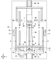
図1は、本発明の一実施の形態による基板の位置決め装置の上面図である。本実施の形態は、ガラス基板の検査装置に用いられる位置決め装置の例を示している。 FIG. 1 is a top view of a substrate positioning apparatus according to an embodiment of the present invention. This embodiment shows an example of a positioning device used in a glass substrate inspection device.
位置決め装置の上面には、ワークテーブル2が設けられている。ワークテーブル2は、破線で示したガラス基板1を真空吸着して固定するものである。本実施の形態で、図示しない検査装置は、所定の幅の検査光をワークテーブル2に搭載されたガラス基板1へ照射し、ガラス基板1からの反射光又は散乱光を受光して、ガラス基板1の表面の異物等を検査する。このとき、検査装置からの検査光はX方向へ走査される。1回の走査が終了すると、位置決め装置によりガラス基板1をY方向へ所定の距離だけ移動して、次の走査を行う。
A work table 2 is provided on the upper surface of the positioning device. The work table 2 is for fixing the
ワークテーブル2には、3本の溝2a,2b,2cが設けられており、また左右に切り欠き部2d,2eが設けられている。溝2a内には、受けピン5が配置されている。溝2b,2c内には、リフトピン4、受けピン5、及びY方向の位置決めローラ6,7の軸6a,7aが配置されている。切り欠き部2d,2e内には、X方向の位置決めローラ8及びその駆動機構が配置されている。
The work table 2 is provided with three
なお、本実施の形態では、4本のリフトピン4と6本の受けピン5とが設けられているが、リフトピン4及び受けピン5の数は、これに限るものではない。また、本実施の形態では、それぞれ2本の位置決めローラ6,7,8が設けられているが、位置決めローラ6,7,8の数は、これに限るものではない。
In the present embodiment, four
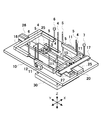
図2は、本発明の一実施の形態による基板の位置決め装置の主要部を示す上面図である。また、図3は、本発明の一実施の形態による基板の位置決め装置の主要部を示す斜視図である。図2及び図3は、図1のワークテーブル2、位置決めローラ8及びその駆動機構を取り外した状態を示している。
FIG. 2 is a top view showing a main part of the substrate positioning apparatus according to the embodiment of the present invention. FIG. 3 is a perspective view showing a main part of the substrate positioning apparatus according to the embodiment of the present invention. 2 and 3 show a state in which the work table 2, the
図3に示すように、リフトピン4はベース30に取り付けられている。ベース30は、図示しない昇降機構によってZ方向へ移動し、これによりリフトピン4が、ベース30の上方に設けられたベース10の溝及び図示しないワークテーブル2の溝2b,2cを通って、上昇及び下降する。
As shown in FIG. 3, the
一方、受けピン5は、E字形のスライドアーム15に取り付けられている。スライドアーム15は、後述する保持機構によって、ベース10に対し移動可能に保持されている。ベース10は、図示しない昇降機構によってZ方向へ移動し、これにより受けピン5が、図示しないワークテーブル2の溝2a,2b,2cを通って、上昇及び下降する。また、ベース10は、図示しない移動機構によってY方向へ移動し、これにより受けピン5が、図示しないワークテーブル2の溝2a,2b,2c内をY方向へ移動する。
On the other hand, the
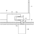
図4は、図2のA−A部の一部断面側面図である。保持機構は、スライドガイド11、スライドブロック12、及びベアリング13を含んで構成されている。スライドガイド11は、ベース10の上面に固定されている。スライドブロック12は、スライドアーム15の側面に固定されている。スライドブロック12の上面及び下面には、ベアリング13が取り付けられており、ベアリング13はスライドガイド11のガイド面11aに接触している。ベアリング13がスライドガイド11のガイド面11aに接触しながら回転すると、スライドブロック12がスライドガイド11に対して移動し、スライドアーム15がベース10に対して移動する。
4 is a partial cross-sectional side view of the AA portion of FIG. The holding mechanism includes a
図2において、スライドアーム15には、ローラ受け22が取り付けられている。一方、スライダ24には、ローラ23が取り付けられている。スライダ24がエアシリンダ25によりY方向へ移動すると、ローラ23がローラ受け22に接触して、スライドアーム15が所定の位置へ移動する。これにより、受けピン5を所定の位置に合わせるセンタリングが行われる。エアシリンダ25は、ベース10上に設けられたプレート20に固定されている。
In FIG. 2, a
図4において、ベース10の下方に設けられたエアシリンダ28の先端には、ストッパ29が取り付けられている。エアシリンダ28によりストッパ29をスライドブロック12へ押し付けると、スライドアーム15が移動できなくなり、受けピン5がロックされる。
In FIG. 4, a
図2において、位置決めローラ6の軸6aは、コの字形の位置決めアーム16に取り付けられている。位置決めアーム16は、エアスライド26によりY方向へ移動し、これにより位置決めローラ6がY方向へ移動する。同様に、位置決めローラ7の軸7aは、コの字形の位置決めアーム17に取り付けられている。位置決めアーム17は、エアスライド27によりY方向へ移動し、これにより位置決めローラ7がY方向へ移動する。エアスライド26,27は、ベース10上に設けられたプレート20に固定されている。
In FIG. 2, the
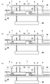
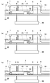
以下、本発明の一実施の形態による基板の位置決め装置の動作を説明する。図5〜図7は、本発明の一実施の形態による基板の位置決め方法を示す図である。作業開始前の状態では、図5(a)に示すように、ベース30及びベース10が下降しており、リフトピン4及び受けピン5の先端が破線で示すワークテーブル2の上面より下方に位置する。
Hereinafter, the operation of the substrate positioning apparatus according to the embodiment of the present invention will be described. 5 to 7 are views showing a substrate positioning method according to an embodiment of the present invention. In the state before the work starts, as shown in FIG. 5A, the
まず、図5(b)に示すように、ベース30を上昇させて、リフトピン4の先端をワークテーブル2の上面から突き出す。この状態で、ロボットアームを用いてガラス基板1をリフトピン4の先端に搭載し、ガラス基板1をロードする。ガラス基板1の下面は、リフトピン4により支持される。
First, as shown in FIG. 5 (b), the
続いて、図5(c)に示すように、ベース10を上昇させて、受けピン5の先端をワークテーブル2の上面から突き出す。そして、図6(a)に示すように、ベース30を下降させてリフトピン4を下降させ、ガラス基板1をリフトピン4から受けピン5へ渡す。ガラス基板1の下面は、受けピン5により支持される。
Subsequently, as shown in FIG. 5C, the
ガラス基板1の下面を受けピン5により支持した状態で、図6(b)に示すように、位置決めローラ6,7,8(位置決めローラ8は図示省略)をY方向又はX方向へ移動する。位置決めローラ6,7,8は、ガラス基板1の側面を押して、ガラス基板1の位置決めを行う。このとき、受けピン5は、保持機構の働きによるスライドアーム15の移動によって、ガラス基板1と共に移動する。
With the lower surface of the
ガラス基板1の位置決めが終了したら、受けピン5をロックし、位置決めローラ6,7,8を元の位置へ戻す。そして、図6(c)に示すように、ベース10を下降させて受けピン5を下降させ、ガラス基板1をワークテーブル2に搭載する。受けピン5を下降させた後、受けピン5のロックを一旦解除し、受けピン5のセンタリングを行って、再び受けピン5をロックする。位置決め装置は、ワークテーブル2によりガラス基板1を真空吸着し、検査装置は、検査光による1回目の走査を行う。
When the positioning of the
1回目の走査が終了したら、ワークテーブル2によるガラス基板1の真空吸着を解除し、ベース10を上昇させて、受けピン5の先端をワークテーブル2の上面から突き出す。ガラス基板1は再び受けピン5で支持され、図6(a)に示した状態となる。
When the first scan is completed, the vacuum suction of the
この状態で、図7(a)に示すように、ベース10を移動することにより、ガラス基板1をY方向へ所定の距離だけ移動する。そして、受けピン5のロックを解除し、図7(b)に示すように、位置決めローラ6,7,8(位置決めローラ8は図示省略)をY方向又はX方向へ移動して、ガラス基板1の位置決めを行う。
In this state, as shown in FIG. 7A, by moving the
ガラス基板1の位置決めが終了したら、受けピン5をロックし、位置決めローラ6,7,8を元の位置へ戻す。そして、図7(c)に示すように、ベース10を下降させて受けピン5を下降させ、ガラス基板1をワークテーブル2に搭載する。受けピン5を下降させた後、受けピン5のロックを一旦解除し、受けピン5のセンタリングを行って、再び受けピン5をロックする。位置決め装置は、ワークテーブル2によりガラス基板1を真空吸着し、検査装置は、検査光による2回目の走査を行う。以後、同様の動作を繰り返して、ガラス基板1の表面全体の走査を行う。
When the positioning of the
ガラス基板1の表面全体の走査が終了したら、ベース10を移動することにより、ガラス基板1をY方向の元の位置へ移動する。そして、ベース30を上昇させて、リフトピン4の先端をワークテーブル2の上面から突き出し、ガラス基板1を受けピン5からリフトピン4へ渡す。続いて、ベース10を下降させて、受けピン5を下降させる。ガラス基板1はリフトピン4で支持され、図5(b)に示した状態となる。この状態で、ロボットアームを用いてガラス基板1をリフトピン4の先端から持ち上げ、ガラス基板1をアンロードする。
When the scanning of the entire surface of the
以上説明した実施の形態によれば、ガラス基板の位置決めを行う際、エアを用いないので塵埃が発生せず、またガラス基板の下面を支持するピンがガラス基板と共に移動するので、ガラス基板の下面に傷が付かない。そして、ワークテーブルを移動する場合に比べ、ガラス基板の位置決めを低コストで行うことができる。 According to the embodiment described above, when the glass substrate is positioned, no air is used, so that dust is not generated, and the pins supporting the lower surface of the glass substrate move together with the glass substrate. Is not scratched. And compared with the case where a work table is moved, positioning of a glass substrate can be performed at low cost.
また、ガラス基板の下面を支持する前に、受けピンを所定の位置に合わせるセンタリングを行うことにより、常にガラス基板の下面の同じ位置を支持することができる。 In addition, by performing centering for aligning the receiving pin with a predetermined position before supporting the lower surface of the glass substrate, it is possible to always support the same position on the lower surface of the glass substrate.
さらに、受けピンが取り付けられたスライドアームを固定するロック機構を設けることにより、ガラス基板のY方向への移動等受けピンの移動が必要ないときに、受けピンをロックすることができる。 Furthermore, by providing a lock mechanism for fixing the slide arm to which the receiving pin is attached, the receiving pin can be locked when it is not necessary to move the receiving pin such as movement of the glass substrate in the Y direction.
本発明は、基板の検査に限らず、表示用パネルの製造工程で基板の位置決めが必要な場合にも適用することができる。 The present invention can be applied not only to the inspection of the substrate but also to the case where the substrate needs to be positioned in the manufacturing process of the display panel.
1 ガラス基板
2 ワークテーブル
4 リフトピン
5 受けピン
6,7,8 位置決めローラ
10,30 ベース
11 スライドガイド
12 スライドブロック
13 ベアリング
15 スライドアーム
16,17 位置決めアーム
20 プレート
22 ローラ受け
23 ローラ
24 スライダ
25,28 エアシリンダ
26,27 エアスライド
29 ストッパ
DESCRIPTION OF
Claims (5)
前記複数のピンが取り付けられた可動部材と、
前記可動部材を移動可能に保持する保持機構と、
前記複数のピンにより支持された基板の側面を押して、基板の位置決めを行う位置決め手段とを備え、
前記複数のピンは、前記位置決め手段により基板の側面が押されたとき、前記保持機構に保持された前記可動部材の移動によって、基板と共に移動することを特徴とする基板の位置決め装置。 A plurality of pins for supporting the lower surface of the substrate;
A movable member to which the plurality of pins are attached;
A holding mechanism for movably holding the movable member;
Positioning means for positioning the substrate by pressing the side surface of the substrate supported by the plurality of pins,
The plurality of pins move together with the substrate by the movement of the movable member held by the holding mechanism when the side surface of the substrate is pushed by the positioning means.
基板の側面を押して、基板を複数のピンと共に移動して基板の位置決めを行うことを特徴とする基板の位置決め方法。 Support the lower surface of the substrate with a plurality of pins attached to the movable member,
A method for positioning a substrate, wherein the substrate is positioned by pressing a side surface of the substrate and moving the substrate together with a plurality of pins.
Priority Applications (1)
| Application Number | Priority Date | Filing Date | Title |
|---|---|---|---|
| JP2004249380A JP2006066747A (en) | 2004-08-30 | 2004-08-30 | Positioning apparatus and method of substrate |
Applications Claiming Priority (1)
| Application Number | Priority Date | Filing Date | Title |
|---|---|---|---|
| JP2004249380A JP2006066747A (en) | 2004-08-30 | 2004-08-30 | Positioning apparatus and method of substrate |
Publications (2)
| Publication Number | Publication Date |
|---|---|
| JP2006066747A true JP2006066747A (en) | 2006-03-09 |
| JP2006066747A5 JP2006066747A5 (en) | 2007-10-18 |
Family
ID=36112928
Family Applications (1)
| Application Number | Title | Priority Date | Filing Date |
|---|---|---|---|
| JP2004249380A Pending JP2006066747A (en) | 2004-08-30 | 2004-08-30 | Positioning apparatus and method of substrate |
Country Status (1)
| Country | Link |
|---|---|
| JP (1) | JP2006066747A (en) |
Cited By (5)
| Publication number | Priority date | Publication date | Assignee | Title |
|---|---|---|---|---|
| JP2008306109A (en) * | 2007-06-11 | 2008-12-18 | Nsk Ltd | Substrate transfer mechanism for exposing device |
| KR200458076Y1 (en) | 2007-04-24 | 2012-01-18 | 삼성전자주식회사 | Print circuit board aligning system |
| KR101324470B1 (en) | 2013-04-03 | 2013-11-01 | 주식회사 트레이스 | Device for alignment of a display panel |
| CN105300111A (en) * | 2014-07-24 | 2016-02-03 | 中外炉工业株式会社 | Platform unit |
| JP2018536986A (en) * | 2015-10-15 | 2018-12-13 | アプライド マテリアルズ インコーポレイテッドApplied Materials,Incorporated | Substrate carrier system |
-
2004
- 2004-08-30 JP JP2004249380A patent/JP2006066747A/en active Pending
Cited By (7)
| Publication number | Priority date | Publication date | Assignee | Title |
|---|---|---|---|---|
| KR200458076Y1 (en) | 2007-04-24 | 2012-01-18 | 삼성전자주식회사 | Print circuit board aligning system |
| JP2008306109A (en) * | 2007-06-11 | 2008-12-18 | Nsk Ltd | Substrate transfer mechanism for exposing device |
| KR101324470B1 (en) | 2013-04-03 | 2013-11-01 | 주식회사 트레이스 | Device for alignment of a display panel |
| CN105300111A (en) * | 2014-07-24 | 2016-02-03 | 中外炉工业株式会社 | Platform unit |
| CN105300111B (en) * | 2014-07-24 | 2018-09-25 | 中外炉工业株式会社 | Platform unit |
| TWI648510B (en) * | 2014-07-24 | 2019-01-21 | 日商中外爐工業股份有限公司 | A surface plate unit |
| JP2018536986A (en) * | 2015-10-15 | 2018-12-13 | アプライド マテリアルズ インコーポレイテッドApplied Materials,Incorporated | Substrate carrier system |
Similar Documents
| Publication | Publication Date | Title |
|---|---|---|
| TWI416095B (en) | Substrate inspection apparatus | |
| JP2006266722A (en) | System and method for inspecting substrate | |
| TW200906695A (en) | Substrate adsorption device, substrate transportation device and external inspection equipment | |
| KR20070094506A (en) | Substrate inspection apparatus | |
| KR20120116880A (en) | Coating apparatus | |
| KR20100044450A (en) | The apparatus for aligning of the cassette for the exposure equipment | |
| JP5005945B2 (en) | Board inspection equipment | |
| JP2007281285A (en) | Substrate transport apparatus | |
| JP2007107884A (en) | Substrate inspection device and substrate inspection method | |
| JP2006066747A (en) | Positioning apparatus and method of substrate | |
| WO2013150787A1 (en) | Object transfer system, exposure apparatus, method for manufacturing flat panel display, device manufacturing method, object holding apparatus, object transfer apparatus, object transfer method, and object replacing method | |
| KR101543875B1 (en) | Apparatus for transferring substrate and apparatus for inspecting substrate including the same | |
| KR100490952B1 (en) | Display panel conveyer for multipurpose optics test having stage type | |
| JP2008076079A (en) | Substrate inspection device | |
| JP4546066B2 (en) | Substrate positioning method and inspection apparatus using this method | |
| JP6322527B2 (en) | Printing apparatus, printing method, and carrier used in the printing apparatus | |
| JP6013212B2 (en) | Pattern forming device | |
| JP2008251944A (en) | Exposure apparatus | |
| JP5928771B2 (en) | Substrate inspection apparatus and substrate inspection method | |
| TW201008856A (en) | Coating apparatus and coating method | |
| TWI352197B (en) | Edge measuring apparatus for glass substrate | |
| KR100483363B1 (en) | Stage system for bypass line of inline inspection machine | |
| TW200424093A (en) | Method for positioning a substrate and inspecting apparatus using same | |
| KR100445278B1 (en) | Apparatus for transferring flat glass used in flat panel display | |
| KR100456486B1 (en) | Substrate fixing device for inspecting edge of glass substrate |
Legal Events
| Date | Code | Title | Description |
|---|---|---|---|
| A711 | Notification of change in applicant |
Free format text: JAPANESE INTERMEDIATE CODE: A712 Effective date: 20060516 |
|
| A521 | Written amendment |
Free format text: JAPANESE INTERMEDIATE CODE: A523 Effective date: 20070824 |
|
| A621 | Written request for application examination |
Free format text: JAPANESE INTERMEDIATE CODE: A621 Effective date: 20070824 |
|
| A977 | Report on retrieval |
Free format text: JAPANESE INTERMEDIATE CODE: A971007 Effective date: 20090930 |
|
| A131 | Notification of reasons for refusal |
Free format text: JAPANESE INTERMEDIATE CODE: A131 Effective date: 20091006 |
|
| A02 | Decision of refusal |
Free format text: JAPANESE INTERMEDIATE CODE: A02 Effective date: 20100216 |