JP2006029247A - Stop and start control device for engine - Google Patents
Stop and start control device for engine Download PDFInfo
- Publication number
- JP2006029247A JP2006029247A JP2004211043A JP2004211043A JP2006029247A JP 2006029247 A JP2006029247 A JP 2006029247A JP 2004211043 A JP2004211043 A JP 2004211043A JP 2004211043 A JP2004211043 A JP 2004211043A JP 2006029247 A JP2006029247 A JP 2006029247A
- Authority
- JP
- Japan
- Prior art keywords
- stop
- engine
- cylinder
- stroke
- time
- Prior art date
- Legal status (The legal status is an assumption and is not a legal conclusion. Google has not performed a legal analysis and makes no representation as to the accuracy of the status listed.)
- Pending
Links
Images


Classifications
-
- F—MECHANICAL ENGINEERING; LIGHTING; HEATING; WEAPONS; BLASTING
- F02—COMBUSTION ENGINES; HOT-GAS OR COMBUSTION-PRODUCT ENGINE PLANTS
- F02N—STARTING OF COMBUSTION ENGINES; STARTING AIDS FOR SUCH ENGINES, NOT OTHERWISE PROVIDED FOR
- F02N99/00—Subject matter not provided for in other groups of this subclass
- F02N99/002—Starting combustion engines by ignition means
- F02N99/004—Generation of the ignition spark
-
- F—MECHANICAL ENGINEERING; LIGHTING; HEATING; WEAPONS; BLASTING
- F02—COMBUSTION ENGINES; HOT-GAS OR COMBUSTION-PRODUCT ENGINE PLANTS
- F02N—STARTING OF COMBUSTION ENGINES; STARTING AIDS FOR SUCH ENGINES, NOT OTHERWISE PROVIDED FOR
- F02N99/00—Subject matter not provided for in other groups of this subclass
- F02N99/002—Starting combustion engines by ignition means
- F02N99/006—Providing a combustible mixture inside the cylinder
-
- F—MECHANICAL ENGINEERING; LIGHTING; HEATING; WEAPONS; BLASTING
- F02—COMBUSTION ENGINES; HOT-GAS OR COMBUSTION-PRODUCT ENGINE PLANTS
- F02N—STARTING OF COMBUSTION ENGINES; STARTING AIDS FOR SUCH ENGINES, NOT OTHERWISE PROVIDED FOR
- F02N99/00—Subject matter not provided for in other groups of this subclass
- F02N99/002—Starting combustion engines by ignition means
- F02N99/008—Providing a combustible mixture outside the cylinder
-
- F—MECHANICAL ENGINEERING; LIGHTING; HEATING; WEAPONS; BLASTING
- F02—COMBUSTION ENGINES; HOT-GAS OR COMBUSTION-PRODUCT ENGINE PLANTS
- F02D—CONTROLLING COMBUSTION ENGINES
- F02D41/00—Electrical control of supply of combustible mixture or its constituents
- F02D41/009—Electrical control of supply of combustible mixture or its constituents using means for generating position or synchronisation signals
- F02D2041/0095—Synchronisation of the cylinders during engine shutdown
Landscapes
- Engineering & Computer Science (AREA)
- Chemical & Material Sciences (AREA)
- Combustion & Propulsion (AREA)
- Mechanical Engineering (AREA)
- General Engineering & Computer Science (AREA)
- Output Control And Ontrol Of Special Type Engine (AREA)
- Combined Controls Of Internal Combustion Engines (AREA)
- Control Of Vehicle Engines Or Engines For Specific Uses (AREA)
- Ignition Installations For Internal Combustion Engines (AREA)
- Electrical Control Of Air Or Fuel Supplied To Internal-Combustion Engine (AREA)
Abstract
Description
本発明は、吸気ポート噴射エンジンをスタータを使用しないで始動する“スタータレス始動”の機能を備えたエンジンの停止始動制御装置に関する発明である。 The present invention relates to an engine stop / start control device having a “starterless start” function for starting an intake port injection engine without using a starter.
近年、筒内噴射エンジンにおいては、特許文献1(特開2002−39038号公報)に示すように、始動時に、膨張行程で停止している気筒内に燃料を噴射して点火することで膨張行程燃焼を発生させ、この膨張行程燃焼の燃焼圧力でクランク軸を回転駆動(クランキング)することで、スタータレス始動を行うようにしたものがある。 2. Description of the Related Art In recent years, in a cylinder injection engine, as shown in Patent Document 1 (Japanese Patent Laid-Open No. 2002-39038), at the time of start-up, fuel is injected into a cylinder stopped in the expansion stroke and ignited so that the expansion stroke Some starterless start is performed by generating combustion and rotationally driving (cranking) the crankshaft with the combustion pressure of the expansion stroke combustion.
この筒内噴射エンジンのスタータレス始動において、始動時に最初に燃料を噴射する膨張行程の気筒は吸気バルブが閉じているため、この技術を吸気ポート噴射エンジンに適用しようとしても、吸気ポート噴射エンジンの膨張行程の気筒には燃料を供給することができないため、筒内噴射エンジンのスタータレス始動の技術を吸気ポート噴射エンジンには適用できない。 In this starterless start of the in-cylinder injection engine, the cylinder of the expansion stroke that injects fuel first at the start is closed with the intake valve. Therefore, even if this technology is applied to the intake port injection engine, the intake port injection engine Since fuel cannot be supplied to the cylinders in the expansion stroke, the starterless start technology for the in-cylinder injection engine cannot be applied to the intake port injection engine.
そこで、吸気ポート噴射エンジンにおいて、スタータレス始動を可能にするため、特許文献2(特開昭62−255558号公報)に示すように、エンジン停止時に常に同じ位置で強制停止させることで、予め決められた特定の気筒が常に膨張行程となるように停止させると共に、その停止直前に、燃料噴射弁から燃料を噴射して上記特定の気筒内に混合気を閉じ込めた位置でエンジンを停止させ、次の始動時に、膨張行程で停止している気筒内の混合気に点火してスタータレス始動を行うようにしたものがある。このものでは、エンジンを常に同じ位置で強制停止させる手段として、所定気筒の吸気ポートにシャッタバルブを設けて、停止直前にこのシャッタバルブを閉じて当該気筒への吸入空気の流入を遮断することで、予め決められた特定の気筒が常に膨張行程となるように強制停止させるようにしている。
しかし、上記特許文献2の技術では、エンジンを常に同じ位置で強制停止させるために、所定気筒の吸気ポートにシャッタバルブを設ける必要があり、ハード的な構成が複雑化して、コスト高になる欠点がある。しかも、エンジンを常に同じ位置で強制停止させるため、エンジン停止位置の間隔がクランク軸2回転(720℃A)分の間隔となる。このため、エンジン停止時に、エンジンの惰性回転の運動エネルギが十分に残っている状態でエンジン回転を早めに強制停止させないと、エンジンの惰性回転が次のエンジン停止位置に達する前に停止してしまう可能性がある。そのため、エンジン停止時に、エンジン回転を早めに急停止させる必要があり、その急停止によりショックが発生するという問題があった。
However, in the technique disclosed in
本発明はこのような事情を考慮してなされたものであり、従ってその目的は、吸気ポート噴射エンジンにおいて、ハード的な構成の変更なしにスタータレス始動を安価に実現できると共に、従来のエンジン急停止によるショックの問題も解決できるエンジンの停止始動制御装置を提供することにある。 The present invention has been made in view of such circumstances. Therefore, the object of the present invention is to realize a starterless start at a low cost without changing the hardware configuration in an intake port injection engine, and to reduce the speed of a conventional engine. An object of the present invention is to provide an engine stop / start control device that can solve the problem of shock due to a stop.
上記目的を達成するために、請求項1に係る発明は、吸気ポート噴射エンジンにおいて、停止時気筒行程予測手段によって、エンジン停止過程において停止時の各気筒の行程を予測し、その予測結果を記憶手段に記憶すると共に、停止時燃料噴射制御手段によって、エンジン停止過程において前記停止時気筒行程予測手段の予測結果に基づいて膨張行程と圧縮行程で停止すると予測された各気筒に対して次の始動時に必要な燃料を噴射して当該気筒内に混合気を閉じ込める。この後、エンジンを始動する際に、スタータレス始動制御手段によって、停止時気筒行程予測手段の予測結果の記憶データに基づいて停止時の膨張行程気筒内の混合気に点火してその燃焼圧力でクランキングを開始し、次の点火タイミングで停止時の圧縮行程気筒内の混合気に点火してエンジンをスタータレス始動する。 In order to achieve the above object, according to a first aspect of the present invention, in an intake port injection engine, a cylinder stroke prediction unit for a stop state predicts a stroke of each cylinder at a stop in an engine stop process and stores the prediction result. Is stored in the means, and the next fuel injection control means performs the next start for each cylinder predicted to stop in the expansion stroke and the compression stroke based on the prediction result of the stop cylinder stroke prediction means in the engine stop process. Sometimes the necessary fuel is injected to confine the mixture in the cylinder. Thereafter, when starting the engine, the starterless start control means ignites the air-fuel mixture in the expansion stroke cylinder at the stop based on the stored data of the prediction result of the stop cylinder stroke prediction means, and at the combustion pressure Cranking is started, and the air-fuel mixture in the compression stroke cylinder at the time of stop is ignited at the next ignition timing, and the engine is started starterlessly.
この構成によれば、エンジン停止過程において停止時の各気筒の行程を予測する機能を備えているため、エンジン停止位置を一定位置に決める必要がない。このため、エンジン停止時に惰性回転するエンジンをその運動を妨げるポンプ損失等の機械的なエネルギ損失によって自然に停止させることができ、従来のエンジン急停止によるショックの問題を解決することができる。しかも、エンジンを一定位置で強制停止させる手段(シャッタバルブ等)を設ける必要がないため、吸気ポート噴射エンジンにおいて、ハード的な構成の変更なしにスタータレス始動を安価に実現できる。 According to this configuration, since the function of predicting the stroke of each cylinder at the time of stopping in the engine stop process is provided, it is not necessary to determine the engine stop position at a fixed position. For this reason, the engine that rotates inertially when the engine is stopped can be stopped naturally by mechanical energy loss such as pump loss that hinders its movement, and the conventional problem of shock due to sudden engine stop can be solved. In addition, since it is not necessary to provide means for forcibly stopping the engine at a fixed position (such as a shutter valve), starterless start can be realized at low cost without changing the hardware configuration in the intake port injection engine.
この場合、停止時の各気筒の行程を予測する際に、請求項2のように、エンジン停止過程においてエンジンの運動を表すパラメータとエンジンの運動を妨げるパラメータとを算出して、これら2つのパラメータに基づいて未来の運動を表すパラメータを予測し、この未来の運動を表すパラメータの予測値に基づいて停止時の各気筒の行程を予測するようにしても良い。このようにすれば、エンジンの運動を表すパラメータやエンジンの運動を妨げるパラメータを算出する過程で、エンジンの製造公差、経時変化、エンジンフリクションの変化(例えばエンジンオイルの油温変化による粘度の違い等)によるバラツキを考慮して、未来の運動を表すパラメータを精度良く予測することができるため、この未来の運動を表すパラメータから停止時の各気筒の行程を精度良く予測することができる。
In this case, when predicting the stroke of each cylinder at the time of stop, as shown in
この場合、請求項3のように、エンジン停止過程において前記未来の運動を表すパラメータとして未来の瞬時エンジン回転速度を予測し、この未来の瞬時エンジン回転速度が所定値以下になったときに、その時点の各気筒の行程状態でエンジン回転が停止すると予測するようにすると良い。要するに、エンジン停止過程において、予測した未来の瞬時エンジン回転速度が、ピストンが圧縮TDC(上死点)を乗り越えることができない回転速度領域に低下した段階で、エンジン回転が停止するものと予測するものである。
In this case, as in
また、エンジン停止位置を制御する際に、請求項4のように、停止時気筒行程予測手段により圧縮行程で停止すると予測された気筒が、エンジン停止直前の吸気行程にある期間に吸入空気量を増加させて、停止時の圧縮行程気筒の圧縮圧を増加させることによりエンジン回転を停止させるようにしても良い。このように、エンジン回転停止時に圧縮行程の圧縮圧を増加させると、圧縮行程で発生する負の回転トルクが増加して、これがエンジン回転を妨げる力となって働き、エンジン回転にブレーキがかけられると共に、回転トルクがエンジンフリクション以下となるクランク角範囲(エンジン回転が停止可能なクランク角範囲)が狭められ、そのクランク角範囲内でエンジン回転が停止することになる。これにより、エンジン停止位置(膨張行程気筒のピストンの停止位置)をスタータレス始動に適した位置に制御することが可能となる。しかも、現状のエンジンに装備されている吸入空気量可変手段(例えばアイドル回転速度制御バルブ、電子スロットルバルブ、可変バルブ機構等)を利用してエンジン停止位置を制御することができ、新たな装置を追加する必要がない。
Further, when the engine stop position is controlled, as in
以上説明した請求項1〜4に係る発明は、運転者がイグニッションスイッチを操作してエンジン停止・始動を行う場合にも適用できるが、請求項5のように、アイドル運転中に所定の自動停止条件が成立したときに燃料噴射及び点火を停止してエンジン回転を停止させる自動停止手段を備えたアイドルストップシステムに本発明を適用し、自動停止手段によるエンジン停止時(アイドルストップ時)に、膨張行程と圧縮行程で停止すると予測された各気筒に燃料を噴射して当該気筒内に混合気を閉じ込め、所定の自動始動条件が成立したときに、停止時の膨張行程気筒内の混合気に点火してその燃焼圧力でクランキングを開始して再始動するようにすると良い。このようにすれば、吸気ポート噴射エンジンのアイドルストップシステムにおけるスタータレス始動を、ハード的な構成の変更なしに安価に実現できると共に、スタータの駆動音による騒音を低減でき、静粛化の要求も満たすことができる。
The inventions according to
また、エンジンをクランキングするスタータを搭載した車両に本発明を適用する場合には、請求項6のように、スタータレス始動が可能であるか否かをエンジン停止位置、停止時間、温度状態等に基づいて判定し、スタータレス始動が困難と判定した場合にスタータによる始動に切り替えるようにすると良い。例えば、停止時の膨張行程気筒であっても、ピストンの停止位置が下死点(BDC)に近い場合は、停止時の膨張行程気筒に点火しても、直ぐに排気バルブが開弁されて燃焼圧力が逃げてしまうため、始動に必要な最低限のトルク(圧縮行程気筒のピストンが圧縮上死点を乗り越えるのに必要なトルク)を確保できず、スタータレス始動に失敗する可能性がある。また、エンジン停止時に膨張行程と圧縮行程の気筒内に閉じ込められた混合気は、ピストンで圧縮されて圧力が大気圧より高くなっているため、エンジン停止時間が長くなるに従って、各気筒内の混合気が吸排気バルブの隙間やピストンの隙間から徐々に漏れていく。このため、エンジン停止時間が長くなると、膨張行程気筒・圧縮行程気筒内の混合気が少なくなって、燃焼不良や失火が発生しやすくなり、スタータレス始動に失敗する可能性がある。また、エンジン温度(冷却水温)や吸気温度が低いときには、混合気の燃焼性が悪化して、燃焼不良や失火が発生しやすくなり、スタータレス始動に失敗する可能性がある。従って、エンジン停止位置、停止時間、温度状態等に基づいてスタータレス始動が可能であるか否かを判定すれば、スタータレス始動に失敗する可能性がある場合に、スタータによる始動に切り替えることができ、始動性を確保することができる。 Further, when the present invention is applied to a vehicle equipped with a starter for cranking the engine, whether or not starterless start is possible is determined as in claim 6, such as engine stop position, stop time, temperature state, etc. It is preferable to switch to starter start when it is determined that starterless start is difficult. For example, even in the case of an expansion stroke cylinder at the time of stop, if the stop position of the piston is close to bottom dead center (BDC), even if the expansion stroke cylinder at the time of stop is ignited, the exhaust valve is immediately opened and burned. Since the pressure escapes, the minimum torque required for starting (the torque required for the piston of the compression stroke cylinder to overcome the compression top dead center) cannot be secured, and starterless starting may fail. In addition, the air-fuel mixture trapped in the cylinders of the expansion stroke and the compression stroke when the engine is stopped is compressed by the piston and the pressure is higher than the atmospheric pressure, so the mixture in each cylinder increases as the engine stop time increases. The air gradually leaks from the gap between the intake and exhaust valves and the gap between the pistons. For this reason, if the engine stop time becomes long, the air-fuel mixture in the expansion stroke cylinder and the compression stroke cylinder decreases, and combustion failure and misfire are likely to occur, and starterless start may fail. In addition, when the engine temperature (cooling water temperature) or the intake air temperature is low, the combustibility of the air-fuel mixture deteriorates and combustion failure or misfire tends to occur, and starterless start may fail. Therefore, if it is determined whether starterless start is possible based on the engine stop position, stop time, temperature state, etc., starterless start can be switched to when starterless start is likely to fail. And startability can be ensured.
以下、本発明を実施するための最良の形態を吸気ポート噴射方式の4気筒エンジンにて具体化した一実施例を説明する。 Hereinafter, an embodiment in which the best mode for carrying out the present invention is embodied in an intake port injection type four-cylinder engine will be described.
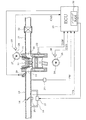
まず、図1に基づいてエンジン制御システム全体の構成を概略的に説明する。エンジン11の吸気ポート12に接続された吸気管13の途中には、スロットルバルブ14が設けられ、このスロットルバルブ14の開度(スロットル開度)TAがスロットル開度センサ15によって検出される。吸気管13には、スロットルバルブ14をバイパスするバイパス通路16が設けられ、このバイパス通路16の途中に、アイドルスピードコントロールバルブ(以下「ISCバルブ」と表記する)17が設けられている。スロットルバルブ14の下流側には、吸気管圧力PMを検出する吸気管圧力センサ18が設けられ、各気筒の吸気ポート12の近傍には、燃料噴射弁19が取りつけられている。
First, the overall configuration of the engine control system will be schematically described with reference to FIG. A
一方、エンジン11の排気ポート20に接続された排気管21の途中には、排気ガス浄化用の触媒22が設置されている。エンジン11のシリンダブロックには、冷却水温THWを検出する冷却水温センサ23が設けられている。エンジン11のクランク軸24に取付けられたシグナルロータ25の外周に対向してクランク角センサ26が設置され、このクランク角センサ26からシグナルロータ25の回転に同期して所定クランク角毎(例えば10℃A毎)にクランク信号のパルスが出力される。このクランク角センサ26のシグナルロータ25には、1個〜数個分の歯(パルス)が欠けた連続欠け歯と単一欠け歯(図8参照)が設けられ、これら連続欠け歯と単一欠け歯とによってクランク角基準位置が検出されるようになっている。また、エンジン11のカム軸27に取付けられたシグナルロータ28の外周に対向してカム角センサ29が設置され、このカム角センサ29からシグナルロータ28の回転に同期して所定のカム角でカム信号のパルスが出力される。
On the other hand, an exhaust gas purifying
これら各種センサの出力は、エンジン制御回路(以下「ECU」と表記する)30に入力される。このECU30は、マイクロコンピュータを主体として構成され、各種センサで検出したエンジン運転状態に応じて、燃料噴射弁19の燃料噴射量や噴射時期、点火プラグ31の点火時期、ISCバルブ17の開度(バイパス空気量)等を制御する。また、このECU30は、アイドル運転中に所定の自動停止条件が成立して、アイドルストップ信号がON(オン)になったときには、燃料噴射及び点火を停止してエンジン回転を停止させる自動停止手段として機能すると共に、このアイドルストップによるエンジン停止中に運転者のアクセル操作等の所定の自動始動条件が成立したときに、スタータレス始動制御を開始し、エンジン停止時の膨張行程気筒内の混合気に点火してその燃焼圧力でクランキングを開始し、次の点火タイミングでエンジン停止時の圧縮行程気筒内の混合気に点火して再始動させるスタータレス始動制御手段として機能する。
Outputs of these various sensors are input to an engine control circuit (hereinafter referred to as “ECU”) 30. The ECU 30 is mainly composed of a microcomputer, and in accordance with the engine operating state detected by various sensors, the fuel injection amount and injection timing of the
更に、このECU30は、後述する図7乃至図9の各ルーチンを実行することで、クランク信号とカム信号に基づいて、クランク角判定、気筒判別、エンジン回転速度の演算と記憶、運動エネルギの演算と記憶、エンジンの運動を妨げる仕事量の演算と記憶、未来の運動エネルギ予測値の演算、未来の瞬時エンジン回転速度予測値の演算、エンジン停止位置(エンジン停止時の各気筒の行程状態)の予測とISCバルブ17による停止位置制御を行なう。このエンジン停止位置の情報は、バックアップRAM32(書き換え可能な不揮発性メモリ)又はRAMに記憶され、次のエンジン始動時に、このエンジン停止位置の記憶情報を用いて、スタータレス始動制御を実行する。
Further, the ECU 30 executes routines shown in FIGS. 7 to 9 to be described later, so that crank angle determination, cylinder discrimination, calculation and storage of engine speed, calculation of kinetic energy based on the crank signal and the cam signal. And memory, calculation and storage of work amount that hinders engine movement, calculation of future kinetic energy prediction value, calculation of future instantaneous engine rotation speed prediction value, engine stop position (stroke state of each cylinder when engine is stopped) Prediction and stop position control by the
ここで、図2に示すエンジン停止過程のタイムチャートを用いてエンジン停止位置の推定方法を説明する。本実施例では、エンジンの運動を表すパラメータとして、各圧縮TDCにおける瞬間のエンジン回転速度(以下「瞬時回転速度」と表記する)を用いる。ECU30は、クランク信号のパルス間隔からクランク軸24が例えば10℃A回転するのに要する時間を計測して、瞬時回転速度Neを算出する。
Here, the method for estimating the engine stop position will be described with reference to the time chart of the engine stop process shown in FIG. In this embodiment, the instantaneous engine rotation speed (hereinafter referred to as “instantaneous rotation speed”) at each compression TDC is used as a parameter representing the engine motion. The ECU 30 measures the time required for the
ここで、図2のi番目の圧縮TDC(以下、単に「TDC(i) 」と表記する)におけるエネルギの収支について考える。本実施例では、エンジンの運動を妨げる仕事として、ポンプ損失、各部の摩擦損失、各補機の駆動損失を考慮する。TDC(i-1) の時点で、エンジンが持っている運動エネルギをE(i-1) とすると、次のTDC(i) に到達するまでに、この運動エネルギE(i-1) が前記各損失による仕事により奪われ、E(i) まで減少する。このエネルギ収支の関係は、次の(1)式のように表される。 Here, the energy balance in the i-th compressed TDC (hereinafter simply referred to as “TDC (i)”) in FIG. 2 is considered. In this embodiment, pump loss, friction loss of each part, and drive loss of each auxiliary machine are taken into consideration as work that hinders engine movement. Assuming that the kinetic energy of the engine at the time of TDC (i-1) is E (i-1), this kinetic energy E (i-1) is the above-mentioned before reaching the next TDC (i). Lost to E (i) by being deprived of work by each loss. This energy balance relationship is expressed by the following equation (1).
E(i) =E(i-1) −W ……(1)
ここで、Wは、TDC(i-1) からTDC(i) までの間に前記各損失により奪われた仕事量を全て加算したものである。
E (i) = E (i-1) -W (1)
Here, W is the sum of all the work deprived by each loss between TDC (i-1) and TDC (i).
また、エンジンの運動を回転運動とみなして、次の(2)式のように表すことができる。
E=J×2π2 ×Ne2 ……(2)
ここで、Eはエンジンのもつ運動エネルギ、Jはエンジン毎に決まる慣性モーメント、Neは瞬時回転速度である。
Further, the engine motion can be regarded as a rotational motion and expressed as the following equation (2).
E = J × 2π 2 × Ne 2 (2)
Here, E is the kinetic energy of the engine, J is the moment of inertia determined for each engine, and Ne is the instantaneous rotational speed.
この(2)式を用いることで、前記(1)式のエネルギ収支の関係を次の(3)式で表される瞬時回転速度変化の関係に置き換えることができる。 By using the equation (2), the relationship of the energy balance of the equation (1) can be replaced with the relationship of the instantaneous rotational speed change represented by the following equation (3).

上記(3)式の右辺の第2項をエンジンの運動を妨げるパラメータCstopとし、次の(4)式のように定義する。 The second term on the right side of the above equation (3) is defined as the following equation (4), which is a parameter Cstop that hinders engine motion.
このエンジンの運動を妨げるパラメータCstopは、上記(3)式と(4)式から導き出される次の(5)式を用いて算出する。
Cstop=Ne(i-1)2 −Ne(i)2 ……(5)
The parameter Cstop that hinders the motion of the engine is calculated using the following equation (5) derived from the above equations (3) and (4).
Cstop = Ne (i-1) 2 −Ne (i) 2 (5)
また、エンジンの運動を妨げるパラメータCstopは、上記(4)式で定義されるように、TDC間の各損失による運動を妨げる仕事量Wと慣性モーメントJにより決まる。エンジン停止過程のような低回転の運動条件では、図4に示すように、運動を妨げる仕事として考慮したポンプ損失、各部の摩擦損失、各補機の駆動損失はエンジン回転速度Neに依らずほぼ一定値となる。従って、エンジンの運動を妨げる仕事量Wは、エンジン停止過程のどのTDC間においてもほぼ一定値となる。加えて、慣性モーメントJは各エンジンに固有の値であるため、エンジンの運動を妨げるパラメータCstopはエンジンの停止過程の期間ではほぼ一定値となる。 The parameter Cstop that hinders the motion of the engine is determined by the work amount W and the moment of inertia J that hinder the motion due to each loss between the TDCs, as defined by the above equation (4). Under low rotation motion conditions such as the engine stop process, as shown in FIG. 4, the pump loss, friction loss of each part, and drive loss of each auxiliary machine considered as work that hinders the motion are almost independent of the engine rotational speed Ne. It becomes a constant value. Therefore, the work amount W that hinders the motion of the engine becomes a substantially constant value during any TDC in the engine stop process. In addition, since the moment of inertia J is a value unique to each engine, the parameter Cstop that hinders the movement of the engine is a substantially constant value during the engine stop process.
従って、実測による現在の瞬時回転速度Ne(i) と、前記(5)式を用いて算出したTDC間に運動を妨げるパラメータCstopとを用いて、次の(6a)式又は(6b)式により、一つ未来のTDC(i+1) における瞬時回転速度Ne(i+1) の予測値を算出することができる。 Therefore, using the current instantaneous rotational speed Ne (i) actually measured and the parameter Cstop that prevents movement between the TDCs calculated using the above equation (5), the following equation (6a) or (6b) is used. The predicted value of the instantaneous rotational speed Ne (i + 1) at one future TDC (i + 1) can be calculated.
ここで、Ne(i)2 <Cstopの場合は、現在エンジンが持っている運動エネルギE(i) よりも、TDC間の運動を妨げる仕事量Wが大きくなる時であり、演算結果が虚数になるのを避けるため、Ne(i+1)=0とする。 Here, if Ne (i) 2 <Cstop, this is the time when the amount of work W that hinders the movement between TDCs becomes larger than the kinetic energy E (i) that the engine currently has, and the calculation result is an imaginary number. In order to avoid this, Ne (i + 1) = 0.
以上のようにして算出される一つ未来のTDC(i+1) における瞬時回転速度Ne(i+1) の予測値を用いて、エンジン停止位置における各気筒の行程状態(停止時の圧縮行程気筒)を予測する場合は、一つ未来のTDC(i+1) における瞬時回転速度Ne(i+1) の予測値を予め設定された停止判定値Nthと比較することで、エンジン回転が停止するかどうかを判断し、エンジン停止位置における各気筒の行程状態(停止時の圧縮行程気筒)を推定するという方法がある。 Using the predicted value of the instantaneous rotational speed Ne (i + 1) at one future TDC (i + 1) calculated as described above, the stroke state of each cylinder at the engine stop position (the compression stroke at the stop) When the cylinder) is predicted, the engine rotation is stopped by comparing the predicted value of the instantaneous rotational speed Ne (i + 1) at one future TDC (i + 1) with a preset stop determination value Nth. There is a method of determining whether or not to perform and estimating the stroke state of each cylinder at the engine stop position (compression stroke cylinder at the time of stop).
この推定方法では、一つ未来のTDCにおける瞬時回転速度の予測値でエンジン回転が停止するか否かを判定するため、エンジン停止位置は、エンジン回転が停止する間際でなければ推定することができない。 In this estimation method, it is determined whether or not the engine rotation is stopped based on the predicted value of the instantaneous rotational speed at one future TDC. Therefore, the engine stop position can be estimated only when the engine rotation is stopped. .
そこで、後述する図8のエンジン停止時気筒状態予測ルーチンでは、未来の瞬時回転速度の予測値と運動を妨げるパラメータを用いて、更に未来の瞬時回転速度を予測するという処理を、エンジン回転停止と判断されるまで繰り返すことで、エンジン回転が停止する間際でなくても、エンジン停止位置を推定できるようにしている。 Therefore, in the cylinder stoppage state prediction routine of FIG. 8 to be described later, the process of predicting the future instantaneous rotation speed using the predicted value of the future instantaneous rotation speed and the parameter that hinders the movement is referred to as engine rotation stop. By repeating until the determination is made, the engine stop position can be estimated even when the engine rotation is not stopped.
以下、このエンジン停止位置の推定方法を図3のタイムチャートを用いて説明する。エンジン停止過程のあるTDC(i) において、前記推定方法と同様の方法で、エンジンの運動を妨げるパラメータCstopと一つ未来のTDC(i+1) における瞬時回転速度Ne(i+1) の予測値を算出する。 Hereinafter, this engine stop position estimation method will be described with reference to the time chart of FIG. In the TDC (i) where the engine is stopped, the parameter Cstop which hinders the engine motion and the prediction of the instantaneous rotational speed Ne (i + 1) in the future TDC (i + 1) by the same method as the above estimation method. Calculate the value.
前述したように、エンジンの運動を妨げるパラメータCstopは、エンジン停止過程の期間ではほぼ一定値となるため、算出したCstopとNe(i+1) を用いて、次の(7a)、(7b)式により、現在より二つ未来のTDC(i+2) における瞬時回転速度Ne(i+2) の予測値を算出する。 As described above, the parameter Cstop that hinders the engine motion is substantially constant during the engine stop process, so the following (7a) and (7b) are calculated using the calculated Cstop and Ne (i + 1). The predicted value of the instantaneous rotational speed Ne (i + 2) at two future TDC (i + 2) from the present is calculated by the equation.
このようにして、未来のTDCにおける瞬時回転速度の予測値を算出する処理を、その瞬時回転速度の予測値が停止判定値を下回るまで繰り返し実行し、瞬時回転速度の予測値が停止判定値を下回ったTDCの手前でエンジン回転が停止するものと推定する。 In this way, the process of calculating the predicted value of the instantaneous rotational speed in the future TDC is repeatedly executed until the predicted value of the instantaneous rotational speed falls below the stop determination value, and the predicted value of the instantaneous rotational speed is set to the stop determination value. It is presumed that engine rotation stops before the lower TDC.
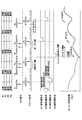
次に、エンジン回転停止制御の概要を図5のタイムチャートを用いて説明する。
図5に示すように、アイドル運転中にアイドルストップ信号がONして、燃料噴射と点火の両方が停止された場合、その後も、暫く、エンジン11は慣性エネルギーにより回転し続けるが、各損失(ポンプ損失,摩擦損失,補機駆動損失等)によりエンジン回転は低下してゆく。このエンジン停止過程において、停止時の各気筒の行程状態を予測し、圧縮行程で停止すると予測された気筒(図5の例では#4気筒)が、停止直前の吸気行程にある期間(好ましくは吸気行程開始時又はそれに近い時期)にISCバルブ17を全開して吸入空気量を増加させることで、停止時の圧縮行程気筒の圧縮圧を増加させてエンジン回転を妨げる力を増加させて、エンジン回転を強制的に停止させる。
Next, the outline of the engine rotation stop control will be described with reference to the time chart of FIG.
As shown in FIG. 5, when the idle stop signal is turned ON during idle operation and both fuel injection and ignition are stopped, the
エンジン停止過程において、停止時の各気筒の行程を予測し終えた後は、膨張行程で停止すると予測された気筒(図5の例では#3気筒)と圧縮行程で停止すると予測された気筒(図5の例では#4気筒)に対して、それぞれ、停止直前の吸気行程の期間(好ましくは吸気行程開始時又はそれに近い時期)に次の始動に必要な燃料を噴射すると共に、上述したISCバルブ17の全開動作により停止時の圧縮行程気筒の圧縮圧を増加させて、停止時の圧縮行程気筒と膨張行程気筒内に混合気を閉じ込めた状態で停止させる。
In the engine stop process, after predicting the stroke of each cylinder at the time of stop, the cylinder predicted to stop in the expansion stroke (# 3 cylinder in the example of FIG. 5) and the cylinder predicted to stop in the compression stroke (# In the example of FIG. 5, the fuel required for the next start is injected during the intake stroke period (preferably at the start of the intake stroke or close to the intake stroke) immediately before the stop, and the ISC described above is used. When the
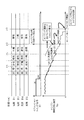
次に、図6のタイムチャートを用いてスタータレス始動制御を説明する。図6の例では、点火順序は、#1気筒→#3気筒→#4気筒→#2気筒の順序であり、クランク信号の連続欠け歯と単一欠け歯とカム信号のパルスとの位置関係に基づいて気筒判別やTDCの判定を行うようにしている。図6の例では、停止時の圧縮行程気筒が#4気筒、膨張行程気筒が#3気筒であり、これら#4,#3気筒内に混合気(燃料)が閉じ込められた状態で停止している。 Next, starterless start control will be described using the time chart of FIG. In the example of FIG. 6, the ignition order is the order of # 1 cylinder → # 3 cylinder → # 4 cylinder → # 2 cylinder, and the positional relationship between the continuous missing tooth of the crank signal, the single missing tooth, and the pulse of the cam signal. Based on the above, cylinder discrimination and TDC determination are performed. In the example of FIG. 6, the compression stroke cylinder at the time of stop is # 4 cylinder and the expansion stroke cylinder is # 3 cylinder, and the mixture is stopped in a state where the mixture (fuel) is confined in the # 4 and # 3 cylinders. Yes.
このアイドルストップによるエンジン停止中に、運転者のアクセル操作等の所定の自動始動条件が成立したときに、スタータレス始動制御を次のようにして実行する。まず、バックアップRAM32に記憶されている停止時の各気筒の行程の記憶情報を読み込む。そして、停止時の膨張行程気筒(図6の例では#3気筒)の混合気に点火してその燃焼圧力でクランキングを開始して、クランク軸を回転駆動する。この後、クランク信号のパルス間隔に基づいて停止時の圧縮行程気筒(図6の例では#4気筒)の例えばBTDC5℃A(クランク信号の単一欠け歯)を検出した時点で、気筒判別を完了し、停止時の圧縮行程気筒(図6の例では#4気筒)に対して所定の点火タイミングで点火する。これにより、#3気筒→#4気筒の順序で点火して連爆させることで、スタータ(図示せず)を使用せずにエンジン11を始動する。
When a predetermined automatic start condition such as an accelerator operation by the driver is satisfied while the engine is stopped by the idle stop, the starterless start control is executed as follows. First, the storage information of the stroke of each cylinder at the time of stop stored in the
また、最初に停止時の膨張行程気筒(図6の例では#3気筒)に点火してクランキングを開始する時に、停止時の吸気行程気筒(図6の例では#2気筒)に燃料を噴射し、気筒判別を完了した後は、各気筒の吸気行程に同期して燃料を噴射して、各気筒の圧縮行程の圧縮TDCに同期して点火を実行する。 In addition, when cranking is started by first igniting the expansion stroke cylinder (# 3 cylinder in the example of FIG. 6) at the time of stop, fuel is supplied to the intake stroke cylinder (# 2 cylinder in the example of FIG. 6) at the time of stop. After the injection and the cylinder discrimination are completed, fuel is injected in synchronization with the intake stroke of each cylinder, and ignition is executed in synchronization with the compression TDC of the compression stroke of each cylinder.
以上説明したエンジン停止時及びスタータレス始動時の制御は、ECU30によって図7乃至図9の各ルーチンに従って実行される。以下、これら各ルーチンの処理内容を説明する。 The control at the time of engine stop and starterless start described above is executed by the ECU 30 according to the routines of FIGS. The processing contents of these routines will be described below.
[エンジン停止制御ルーチン]
図7のエンジン停止制御ルーチンは、例えばTDC毎に繰り返し実行される。本ルーチンが起動されると、まずステップ100で、アイドルストップ信号がONであるか否かを判定し、アイドルストップ信号がOFFであれば、以降の処理を行うことなく、本ルーチンを終了する。
[Engine stop control routine]
The engine stop control routine of FIG. 7 is repeatedly executed for each TDC, for example. When this routine is activated, it is first determined in
一方、アイドルストップ信号がONであれば、ステップ101に進み、燃料噴射及び点火を停止してエンジンを自動停止する。これらステップ100〜101の処理が特許請求の範囲でいう自動停止手段としての役割を果たす。この後、ステップ102に進み、エンジン停止過程におけるTDCの回数をカウントするTDCカウンタCtdc のカウント値が所定値kTDC (例えば1又は2)以上であるか否かを判定し、このTDCカウンタCtdc のカウント値が所定値kTDC 未満であれば、以降の処理を行うことなく、本ルーチンを終了する。このようにする理由は、燃料噴射・点火を停止した直後は、まだエンジン回転速度Neが高く、エンジンの運動を妨げるパラメータCstopを安定した状態で算出することが困難であり、エンジン停止位置を精度良く予測することが困難であるためである。
On the other hand, if the idle stop signal is ON, the process proceeds to step 101, where fuel injection and ignition are stopped and the engine is automatically stopped. The processing of these
その後、TDCカウンタCtdc のカウント値が所定値kTDC 以上になった時点で、ステップ103に進み、後述する気筒状態予測済みフラグXEGがエンジン停止時の気筒状態を予測済みでないことを意味する“0”であるか否かを判定し、「Yes」と判定された場合(つまり気筒状態予測済みフラグXEG=0の場合)には、ステップ104に進み、後述する図8のエンジン停止時気筒状態予測ルーチンを実行して、エンジン停止時の気筒状態(膨張行程気筒CESTCMPと圧縮行程気筒CEGSTIN)を予測して、ステップ105に進む。上記ステップ103で、「No」と判定された場合(つまり気筒状態予測済みフラグXEG=1の場合)には、エンジン停止時の気筒状態を予測済みであるため、ステップ104を飛び越してステップ105に進む。 Thereafter, when the count value of the TDC counter Ctdc becomes equal to or greater than the predetermined value kTDC, the routine proceeds to step 103 where “0” means that the cylinder state predicted flag XEG described later has not predicted the cylinder state when the engine is stopped. If it is determined as “Yes” (that is, if the cylinder state predicted flag XEG = 0), the routine proceeds to step 104, and a cylinder state prediction routine at the time of engine stop in FIG. Is executed to predict the cylinder state (expansion stroke cylinder CESTCMP and compression stroke cylinder CEGSTIN) when the engine is stopped, and the routine proceeds to step 105. If it is determined “No” in step 103 (that is, if the cylinder state predicted flag XEG = 1), the cylinder state at the time of engine stop has been predicted, so step 104 is skipped and step 105 is performed. move on.
このステップ105では、気筒状態予測済みフラグXEG=1(エンジン停止時の気筒状態を予測済み)であるか否かを判定し、「No」と判定されれば、以降の処理を行うことなく、本ルーチンを終了する。
In this
これに対して、ステップ105で、気筒状態予測済みフラグXEG=1と判定されれば、エンジン停止時の気筒状態を予測済みであると判断して、ステップ106に進み、停止時の膨張行程気筒CEGSTCMPと予測された気筒の現在の行程が停止直前の吸気行程であるか否かを判定し、停止直前の吸気行程でなければ、以降の処理を行うことなく、本ルーチンを終了するが、停止直前の吸気行程であれば、ステップ107に進み、停止時の膨張行程気筒CEGSTCMPと予測された気筒に対して、停止直前の吸気行程の期間(好ましくは吸気行程開始時又はそれに近い時期)に次の始動時の初爆に必要な燃料を噴射する。
On the other hand, if it is determined in
この後、ステップ108に進み、停止時の圧縮行程気筒CEGSTINと予測された気筒の現在の行程が停止直前の吸気行程であるか否かを判定し、停止直前の吸気行程でなければ、以降の処理を行うことなく、本ルーチンを終了するが、停止直前の吸気行程であれば、ステップ109に進み、停止時の圧縮行程気筒CEGSTINと予測された気筒に対して、停止直前の吸気行程の期間(好ましくは吸気行程開始時又はそれに近い時期)に次の始動時の初爆に必要な燃料を噴射する。 Thereafter, the routine proceeds to step 108, where it is determined whether or not the current stroke of the cylinder predicted as the compression stroke cylinder CEGSTIN at the stop is the intake stroke immediately before the stop. If the intake stroke immediately before the stop is completed, the routine proceeds to step 109, and the intake stroke period immediately before the stop is determined for the cylinder predicted to be the compression stroke cylinder CEGSTIN at the stop. The fuel necessary for the first explosion at the next start-up is injected (preferably at the start of the intake stroke or close to it).
この後、ステップ110に進み、ISCバルブ17を全開して吸入空気量を増加させることで、停止時の圧縮行程気筒CEGSTINの圧縮圧を増加させてエンジン回転を妨げる力を増加させて、エンジン回転を強制的に停止させる。この後、ステップ111に進み、エンジン停止制御完了フラグXSTOPを、エンジン停止制御完了を意味する“1”にセットして本ルーチンを終了する。
Thereafter, the process proceeds to step 110, where the
尚、上記ステップ106〜109の処理が特許請求の範囲でいう停止時燃料噴射制御手段としての役割を果たし、ステップ110の処理が特許請求の範囲でいう停止位置制御手段としての役割を果たす。
The processing in
[エンジン停止時気筒状態予測ルーチン]
図8のエンジン停止時気筒状態予測ルーチンは、上記図7のエンジン停止制御ルーチンのステップ104で実行されるサブルーチンであり、特許請求の範囲でいう停止時気筒行程予測手段としての役割を果たす。本ルーチンが起動されると、まずステップ201で、前回のTDC(i-1) での瞬時回転速度Ne(i-1) と現在のTDC(i) での瞬時回転速度Ne(i) を用いて前記(5)式によってエンジンの運動を妨げるパラメータCstopを算出する。
[Cylinder state prediction routine at engine stop]
The engine stop cylinder state prediction routine of FIG. 8 is a subroutine executed in
この後、ステップ202に進み、瞬時回転速度の予測回数をカウントする予測回数カウンタjに初期値「1」をセットする。この後、ステップ203、204、205で、j行程後(最初はj=1)の未来のTDC(i+j) における瞬時回転速度Ne(i+j) の予測値を次のようにして算出する。まず、ステップ203で、Ne(i+j-1)2 ≧Cstopであるか否かを判定し、「Yes」と判定されれば、ステップ204に進み、前記(6a)式を用いてj行程後の未来のTDC(i+j) における瞬時回転速度Ne(i+j) の予測値を算出する。
Thereafter, the process proceeds to step 202, where an initial value “1” is set in a prediction number counter j that counts the number of predictions of instantaneous rotational speed. Thereafter, in
これに対して、Ne(i+j-1)2 <Cstopであれば、ステップ205に進み、j行程後の未来のTDC(i+j) における瞬時回転速度Ne(i+j) の予測値を0とする。 On the other hand, if Ne (i + j-1) 2 <Cstop, the process proceeds to step 205, and the predicted value of the instantaneous rotational speed Ne (i + j) at the future TDC (i + j) after j strokes. Is set to 0.
そして、次のステップ206で、このj行程後の未来の瞬時回転速度Ne(i+j) の予測値が予め設定された停止判定値Nj を下回るか否かで、j行程後の未来のTDC(i+j) を乗り越えられずにエンジン回転が停止するか否かを判定する。その結果、j行程後の未来の瞬時回転速度Ne(i+j) の予測値が停止判定値Nj を上回っている(エンジンがj行程後の未来のTDC(i+j) を乗り越えて回り続ける)と判定されれば、ステップ207に進み、予測回数カウンタjを1だけ増加して、ステップ203〜205の処理に戻り、前述した処理を繰り返す。
Then, in the
以上のようにして、未来の瞬時回転速度Ne(i+j) の予測値の算出を、それが停止判定値Nj を下回るようになるまで繰り返し、未来の瞬時回転速度Ne(i+j) をTDC間隔で順次予測していく。 As described above, the calculation of the predicted value of the future instantaneous rotational speed Ne (i + j) is repeated until the predicted value becomes lower than the stop determination value Nj, and the future instantaneous rotational speed Ne (i + j) is calculated. Predicts sequentially at TDC intervals.
そして、未来の瞬時回転速度Ne(i+j) の予測値が停止判定値Nj を下回った時点で、その瞬時回転速度Ne(i+j) のTDC(i+j) の手前でエンジン回転が停止すると判定して、テップ208に進み、停止すると判定されたj行程後の未来のTDC(i+j) からそれより一つ過去のTDC(i+j-1) までの間における各気筒の行程状態(膨張行程気筒CESTCMPと圧縮行程気筒CEGSTIN)をエンジン停止位置の情報としてバックアップRAM32又はRAMに記憶する。
Then, when the predicted value of the future instantaneous rotational speed Ne (i + j) falls below the stop judgment value Nj, the engine rotation is performed before TDC (i + j) of the instantaneous rotational speed Ne (i + j). It is determined that the engine is to be stopped, and the process proceeds to Step 208. Each cylinder in the period from the future TDC (i + j) after the j-stroke determined to be stopped to the previous TDC (i + j-1) is determined. The stroke state (expansion stroke cylinder CESTCMP and compression stroke cylinder CEGSTIN) is stored in the
例えば、3行程後の未来のTDC(i+3) における瞬時回転速度Ne(i+3) の予測値が停止判定値Nj を下回ったと判定されれば、2行程後の未来のTDC(i+2) から3行程後の未来のTDC(i+3) までの間にエンジン回転が停止すると判定して、TDC(i+2) からTDC(i+3) までの間における各気筒の行程状態(膨張行程気筒CESTCMPと圧縮行程気筒CEGSTIN)をエンジン停止位置の情報としてバックアップRAM32又はRAMに記憶する。この後、ステップ209に進み、気筒状態予測済みフラグXEGを“1”にセットして本ルーチンを終了する。
For example, if it is determined that the predicted value of the instantaneous rotational speed Ne (i + 3) at the future TDC (i + 3) after the third stroke is lower than the stop determination value Nj, the future TDC (i + after the second stroke) 2) to the future TDC (i + 3) after 3 strokes, it is determined that the engine will stop, and the stroke state of each cylinder between TDC (i + 2) and TDC (i + 3) (Expansion stroke cylinder CESTCMP and compression stroke cylinder CEGSTIN) are stored in the
[スタータレス始動制御ルーチン]
図9のスタータレス始動制御ルーチンは、ECU30の電源ON期間中に所定時間毎(例えば8ms毎)に繰り返し起動され、特許請求の範囲でいうスタータレス始動制御手段としての役割を果たす。本ルーチンが起動されると、まずステップ301で、自動始動条件が成立しているか否かを判定する。この自動始動条件は、運転者がアクセルペダルの踏み込み等により車両を発進させるための操作を行ったときに成立する。
[Starterless start control routine]
The starterless start control routine of FIG. 9 is repeatedly activated at predetermined time intervals (for example, every 8 ms) during the power-on period of the ECU 30, and serves as starterless start control means in the claims. When this routine is started, first, at
このステップ301で、自動始動条件が成立していないと判定されれば、アイドルストップ継続中と判断して、以降の処理を行うことなく、本ルーチンを終了するが、自動始動条件が成立していると判定されれば、ステップ302以降の処理によってエンジン11を次のようにして自動始動させる。まず、ステップ302で、エンジン停止制御完了フラグXSTOPがエンジン停止制御完了を意味する“1”であるか否かを判定し、このステップ302で「No」と判定されれば、エンジン停止制御が正常に完了していないため、スタータレス始動を実行できないと判断して、ステップ307に進み、スタータをONして、スタータの動力によりエンジン11をクランキングして、次のステップ308で、通常の燃料噴射・点火制御を実行して、エンジン11を始動する。
If it is determined in
これに対して、エンジン停止制御完了フラグXSTOP=1(エンジン停止制御完了)の場合は、停止時の膨張行程気筒と圧縮行程気筒内に混合気が閉じ込められ、且つ、エンジン停止位置の情報が記憶されているため、スタータレス始動の準備が出来ていると判断して、ステップ303に進み、スタータレス始動実行条件が成立しているか否かをスタータレス始動実行条件判定フラグXSTRLESS=1であるか否かによって判定する。ここで、スタータレス始動実行条件としては、(1) エンジン停止位置がスタータレス始動に適した位置(膨張行程の燃焼圧力によるクランキング力を十分に確保できるクランク角範囲)であること、(2) エンジン停止時間が所定時間以内であること、(3) 冷却水温が所定温度以下であること、(4) 吸気温度が所定温度以下であることである。 On the other hand, when the engine stop control completion flag XSTOP = 1 (engine stop control completion), the air-fuel mixture is confined in the expansion stroke cylinder and the compression stroke cylinder at the time of stop, and information on the engine stop position is stored. Therefore, it is determined that the starterless start is ready, and the process proceeds to step 303, where it is determined whether the starterless start execution condition is satisfied, whether the starterless start execution condition determination flag XSTRLESS = 1. Judge by whether or not. Here, starterless start execution conditions are as follows: (1) The engine stop position is a position suitable for starterless start (a crank angle range that can sufficiently secure the cranking force due to the combustion pressure in the expansion stroke), (2 ) The engine stop time is within a predetermined time, (3) the cooling water temperature is lower than the predetermined temperature, and (4) the intake air temperature is lower than the predetermined temperature.
例えば、停止時の膨張行程気筒であっても、ピストンの停止位置が下死点(BDC)に近い場合は、停止時の膨張行程気筒に点火しても、直ぐに排気バルブが開弁されて燃焼圧力が逃げてしまうため、始動に必要な最低限のトルク(圧縮行程気筒のピストンが圧縮上死点を乗り越えるのに必要なトルク)を確保できず、スタータレス始動に失敗する可能性がある。また、エンジン停止時に膨張行程と圧縮行程の気筒内に閉じ込められた混合気は、ピストンで圧縮されて圧力が大気圧より高くなっているため、エンジン停止時間が長くなるに従って、各気筒内の混合気が吸排気バルブの隙間やピストンの隙間から徐々に漏れていく。このため、エンジン停止時間が長くなると、膨張行程気筒・圧縮行程気筒内の混合気が少なくなって、燃焼不良や失火が発生しやすくなり、スタータレス始動に失敗する可能性がある。また、エンジン温度(冷却水温)や吸気温度が低いときには、混合気の燃焼性が悪化して、燃焼不良や失火が発生しやすくなり、スタータレス始動に失敗する可能性がある。 For example, even in the case of an expansion stroke cylinder at the time of stop, if the stop position of the piston is close to bottom dead center (BDC), even if the expansion stroke cylinder at the time of stop is ignited, the exhaust valve is immediately opened and burned. Since the pressure escapes, the minimum torque required for starting (the torque required for the piston of the compression stroke cylinder to overcome the compression top dead center) cannot be secured, and starterless starting may fail. In addition, the air-fuel mixture trapped in the cylinders of the expansion stroke and the compression stroke when the engine is stopped is compressed by the piston and the pressure is higher than the atmospheric pressure, so the mixture in each cylinder increases as the engine stop time increases. The air gradually leaks from the gap between the intake and exhaust valves and the gap between the pistons. For this reason, if the engine stop time becomes long, the air-fuel mixture in the expansion stroke cylinder and the compression stroke cylinder decreases, and combustion failure and misfire are likely to occur, and starterless start may fail. In addition, when the engine temperature (cooling water temperature) or the intake air temperature is low, the combustibility of the air-fuel mixture deteriorates and combustion failure or misfire tends to occur, and starterless start may fail.
そこで、本実施例では、上記4つの条件(1) 〜(4) を全て満したときに、スタータレス始動実行条件が成立し、いずれか1つでも満たさない条件があれば、スタータレス始動実行条件が不成立となる。ステップ303で、スタータレス始動実行条件が不成立(スタータレス始動実行条件判定フラグXSTRLESS=0)と判定された場合は、スタータレス始動が困難と判断して、ステップ307に進み、スタータをONして、スタータの動力によりエンジン11をクランキングして、次のステップ308で、通常の燃料噴射・点火制御を実行して、エンジン11を始動する。
Therefore, in this embodiment, when all the above four conditions (1) to (4) are satisfied, the starterless start execution condition is satisfied, and if any one of the conditions is not satisfied, the starterless start execution is performed. The condition is not satisfied. If it is determined in
一方、ステップ303で、スタータレス始動実行条件判定フラグXSTRLESS=1(スタータレス始動実行条件が成立)と判定された場合は、ステップ304に進み、バックアップRAM32又はRAMに記憶されているエンジン停止位置の情報から停止時の膨張行程気筒CEGSTCMPを判別して、当該膨張行程気筒CEGSTCMPに点火してその燃焼圧力でクランキングを開始する。
On the other hand, if it is determined in
この後、ステップ305に進み、停止時の圧縮行程気筒CEGSTINのピストンが圧縮TDCに到達するまで待機し、当該圧縮行程気筒CEGSTINのピストンが圧縮TDCに到達した時点で、ステップ306に進み、当該圧縮行程気筒CEGSTINに点火する。この後、ステップ309に進み、エンジン停止制御完了フラグXSTOPをリセットして本ルーチンを終了する。 After that, the process proceeds to step 305 and waits until the piston of the compression stroke cylinder CEGSTIN at the time of stopping reaches the compression TDC. When the piston of the compression stroke cylinder CEGSTIN reaches the compression TDC, the process proceeds to step 306 and the compression The stroke cylinder CEGSTIN is ignited. Thereafter, the process proceeds to step 309, the engine stop control completion flag XSTOP is reset, and this routine is terminated.
以上説明した本実施例では、アイドルストップによるエンジン停止過程において停止時の膨張行程気筒と圧縮行程気筒を予測し、停止時の膨張行程と圧縮行程気筒と予測された気筒に対して、それぞれ、停止直前の吸気行程で燃料を噴射して各気筒内に混合気を吸入させて閉じ込めた状態で停止させ、その後、始動要求が発生したときに、停止時の膨張行程気筒内の混合気に点火してその燃焼圧力でクランキングを開始し、次の点火タイミングで停止時の圧縮行程気筒内の混合気に点火してエンジン11をスタータレス始動するようにしたので、吸気ポート噴射エンジン11のアイドルストップシステムにおけるスタータレス始動を、ハード的な構成の変更なしに安価に実現できると共に、スタータの駆動音による騒音を低減でき、静粛化の要求も満たすことができる。しかも、エンジン停止過程において停止時の各気筒の行程を予測する機能を備えているため、エンジン停止位置を一定位置に決める必要がない。このため、エンジン停止時に惰性回転するエンジンをその運動を妨げるポンプ損失等の機械的なエネルギ損失によって自然に停止させることができ、従来のエンジン急停止によるショックの問題を解決することができる。
In the present embodiment described above, the expansion stroke cylinder and the compression stroke cylinder at the time of stop are predicted in the engine stop process by idle stop, and the cylinders that are predicted as the expansion stroke and the compression stroke cylinder at the time of stop are respectively stopped. Fuel is injected in the previous intake stroke, the air-fuel mixture is sucked into each cylinder and stopped in a confined state, and then when the start request is generated, the air-fuel mixture in the expansion stroke cylinder at the time of stop is ignited. Since the cranking is started with the combustion pressure and the air-fuel mixture in the compression stroke cylinder at the time of stop is ignited at the next ignition timing to start the
尚、本発明は、吸気ポート噴射エンジン11のアイドルストップシステムにに限定されず、運転者がイグニッションスイッチを操作してエンジン停止・始動を行う場合にも適用できる。
Note that the present invention is not limited to the idle stop system of the intake
また、本実施例では、圧縮行程で停止すると予測された気筒が、エンジン停止直前の吸気行程にある期間にISCバルブ17を全開して吸入空気量を増加させて、停止時の圧縮行程気筒の圧縮圧を増加させることによりエンジン回転を停止させるようにしたので、エンジン停止位置(膨張行程気筒のピストンの停止位置)をスタータレス始動に適した位置に制御することが可能となる。しかも、現状のエンジンに装備されているISCバルブ17を利用してエンジン停止位置を制御することができ、新たな装置を追加する必要がないという利点もある。
Further, in the present embodiment, the cylinder predicted to stop in the compression stroke increases the intake air amount by fully opening the
このエンジン停止位置制御を実行する際に、ISCバルブ17に代えて、他の吸入空気量制御手段(例えば電子スロットルバルブ、可変バルブ機構等)を用いて圧縮行程気筒の吸入空気量を増加させるようにしても良い。
When executing this engine stop position control, instead of the
また、本発明は、停止位置制御を行わない構成としても良い。この場合は、エンジン停止位置の予測結果に基づいて、エンジン停止位置がスタータレス始動可能な所定クランク角範囲内となると予測される場合のみ、停止時の膨張行程気筒と圧縮行程気筒に対して燃料を噴射して各気筒内に混合気を閉じ込めて、スタータレス始動を行うようにしても良い。また、停止時の膨張行程気筒と圧縮行程気筒の予測方法を適宜変更しても良い。 The present invention may be configured not to perform stop position control. In this case, fuel is supplied to the expansion stroke cylinder and the compression stroke cylinder at the time of stoppage only when the engine stop position is predicted to be within a predetermined crank angle range in which starterless start is possible based on the prediction result of the engine stop position. May be injected to confine the air-fuel mixture in each cylinder and starterless start may be performed. Further, the prediction method of the expansion stroke cylinder and the compression stroke cylinder at the time of stopping may be appropriately changed.
その他、本発明は、4気筒の吸気ポート噴射エンジンに限定されず、3気筒以下又は5気筒以上の吸気ポート噴射エンジンにも適用して実施することができることは言うまでもない。 In addition, the present invention is not limited to a four-cylinder intake port injection engine, and can be applied to an intake port injection engine having three or less cylinders or five or more cylinders.
11…エンジン、13…吸気管、14…スロットルバルブ、16…バイパス通路、17…ISCバルブ、19…燃料噴射弁、26…クランク角センサ、29…カム角センサ、30…ECU(停止時気筒行程予測手段,停止時燃料噴射制御手段,スタータレス始動制御手段,停止位置制御手段,自動停止手段)、32…バックアップRAM(書き換え可能な不揮発性メモリ)
DESCRIPTION OF
Claims (6)
エンジン停止過程において停止時の各気筒の行程を予測すると共にその予測結果を記憶手段に記憶する停止時気筒行程予測手段と、
エンジン停止過程において前記停止時気筒行程予測手段の予測結果に基づいて膨張行程と圧縮行程で停止すると予測された各気筒に対して次の始動時に必要な燃料を噴射して当該気筒内に混合気を閉じ込める停止時燃料噴射制御手段と、
エンジンを始動する際に前記停止時気筒行程予測手段の予測結果の記憶データに基づいて停止時の膨張行程気筒内の混合気に点火してその燃焼圧力でクランキングを開始し、次の点火タイミングで停止時の圧縮行程気筒内の混合気に点火してエンジンをスタータレス始動するスタータレス始動制御手段と
を備えていることを特徴とするエンジンの停止始動制御装置。 In an engine stop / start control device for an engine that injects fuel into an intake port,
A cylinder stroke prediction means at the time of stop for predicting the stroke of each cylinder at the time of stopping in the engine stop process, and storing the prediction result in the storage means;
In the engine stop process, fuel required for the next start is injected into each cylinder that is predicted to stop in the expansion stroke and the compression stroke based on the prediction result of the cylinder stroke prediction means when stopped, and the air-fuel mixture is injected into the cylinder. Fuel injection control means for stopping when
When starting the engine, based on the stored data of the prediction result of the stop cylinder stroke prediction means, the mixture in the expansion stroke cylinder at the stop is ignited and cranking is started with the combustion pressure, and the next ignition timing And a starterless start control means for starting the engine in a starterless manner by igniting the air-fuel mixture in the compression stroke cylinder at the time of stop.
前記自動停止手段によるエンジン停止過程において前記停止時気筒行程予測手段による停止時の各気筒の行程予測と前記停止時燃料噴射制御手段による停止時の燃料噴射制御を実行し、
前記スタータレス始動制御手段は、前記自動停止手段によるエンジン停止中に所定の自動始動条件が成立したときに、前記停止時気筒行程予測手段の予測結果の記憶データに基づいて停止時の膨張行程気筒内の混合気に点火してその燃焼圧力でクランキングを開始し、次の点火タイミングで停止時の圧縮行程気筒内の混合気に点火してエンジンをスタータレス始動することを特徴とする請求項1乃至4のいずれかに記載のエンジンの停止始動制御装置。 Automatic stop means for stopping fuel injection and ignition to stop engine rotation when a predetermined automatic stop condition is satisfied during idle operation;
In the engine stop process by the automatic stop means, the stroke prediction of each cylinder at the time of stop by the stop cylinder stroke prediction means and the fuel injection control at the time of stop by the stop time fuel injection control means are executed,
The starterless start control means, when a predetermined automatic start condition is satisfied while the engine is stopped by the automatic stop means, is based on the stored data of the prediction result of the stop cylinder stroke prediction means, and the expansion stroke cylinder at the stop The start of the engine is started by igniting the mixture in the compression stroke cylinder at the next ignition timing and igniting the mixture in the compression stroke cylinder at the next ignition timing. The engine stop / start control apparatus according to any one of 1 to 4.
前記スタータレス始動制御手段は、前記スタータレス始動が可能であるか否かをエンジン停止位置、停止時間、温度状態等に基づいて判定し、スタータレス始動が困難と判定した場合に前記スタータによる始動に切り替えることを特徴とする請求項1乃至5のいずれかに記載のエンジンの停止始動制御装置。 It has a starter that cranks the engine,
The starterless start control means determines whether or not the starterless start is possible based on an engine stop position, a stop time, a temperature state, and the like. The engine stop / start control apparatus according to any one of claims 1 to 5, wherein
Priority Applications (3)
| Application Number | Priority Date | Filing Date | Title |
|---|---|---|---|
| JP2004211043A JP2006029247A (en) | 2004-07-20 | 2004-07-20 | Stop and start control device for engine |
| US11/181,819 US7066128B2 (en) | 2004-07-20 | 2005-07-15 | Engine controller for starting and stopping engine |
| DE102005033692A DE102005033692A1 (en) | 2004-07-20 | 2005-07-19 | Motor control for starting and stopping an engine |
Applications Claiming Priority (1)
| Application Number | Priority Date | Filing Date | Title |
|---|---|---|---|
| JP2004211043A JP2006029247A (en) | 2004-07-20 | 2004-07-20 | Stop and start control device for engine |
Publications (1)
| Publication Number | Publication Date |
|---|---|
| JP2006029247A true JP2006029247A (en) | 2006-02-02 |
Family
ID=35655805
Family Applications (1)
| Application Number | Title | Priority Date | Filing Date |
|---|---|---|---|
| JP2004211043A Pending JP2006029247A (en) | 2004-07-20 | 2004-07-20 | Stop and start control device for engine |
Country Status (3)
| Country | Link |
|---|---|
| US (1) | US7066128B2 (en) |
| JP (1) | JP2006029247A (en) |
| DE (1) | DE102005033692A1 (en) |
Cited By (4)
| Publication number | Priority date | Publication date | Assignee | Title |
|---|---|---|---|---|
| JP2007270807A (en) * | 2006-03-31 | 2007-10-18 | Mazda Motor Corp | Control device of multicylinder 4-cycle engine |
| JP2008088942A (en) * | 2006-10-04 | 2008-04-17 | Toyota Motor Corp | Stop position control device for internal combustion engine |
| JP2008133775A (en) * | 2006-11-28 | 2008-06-12 | Toyota Motor Corp | Stop position control device for internal combustion engine |
| JP2022079204A (en) * | 2020-11-16 | 2022-05-26 | ダイハツ工業株式会社 | Control device of internal combustion engine |
Families Citing this family (41)
| Publication number | Priority date | Publication date | Assignee | Title |
|---|---|---|---|---|
| DE10322361A1 (en) * | 2003-05-09 | 2004-11-25 | Robert Bosch Gmbh | Method of starting motor vehicle internal combustion engine involves filling combustion chamber with charge immediately after ignition for holding during stopped phase |
| JP4419655B2 (en) * | 2004-04-08 | 2010-02-24 | 株式会社デンソー | Engine stop / start control device |
| US7146960B2 (en) * | 2004-11-16 | 2006-12-12 | Ford Global Technologies, Llc | Engine shut down using fluid pump to control crankshaft stopping position |
| US7461621B2 (en) * | 2005-09-22 | 2008-12-09 | Mazda Motor Corporation | Method of starting spark ignition engine without using starter motor |
| US7669569B2 (en) * | 2006-06-27 | 2010-03-02 | Gm Global Technology Operations, Inc. | Crankshaft stop positioning control system |
| JP4434241B2 (en) * | 2007-07-06 | 2010-03-17 | トヨタ自動車株式会社 | Internal combustion engine stop / start control device |
| WO2009139040A1 (en) * | 2008-05-12 | 2009-11-19 | トヨタ自動車株式会社 | Stop/start control device for internal combustion engine |
| DE102008041037A1 (en) * | 2008-08-06 | 2010-02-11 | Robert Bosch Gmbh | Method and device of a control for a start-stop operation of an internal combustion engine |
| JP4529190B2 (en) * | 2008-08-08 | 2010-08-25 | 株式会社デンソー | Engine stop control device |
| JP5114340B2 (en) * | 2008-08-08 | 2013-01-09 | 株式会社デンソー | Engine stop control device |
| US8370051B2 (en) * | 2009-01-05 | 2013-02-05 | Ford Global Technologies, Llc | Methods and systems for assisted direct start control |
| JP5241021B2 (en) * | 2009-03-24 | 2013-07-17 | 本田技研工業株式会社 | Engine start control device |
| FR2950388B1 (en) * | 2009-09-23 | 2012-04-20 | Peugeot Citroen Automobiles Sa | METHOD FOR PREDICTING THE ROTATION RPM OF A ROTATION END PHASE ENGINE CRANKSHAFT AND APPLYING THE METHOD TO PREDICTING THE STOP CYLINDER |
| US7962278B1 (en) * | 2009-12-16 | 2011-06-14 | Ford Global Technologies, Llc | Method for starting an engine |
| JP5656013B2 (en) * | 2010-01-11 | 2015-01-21 | 株式会社デンソー | Engine automatic stop / start control device |
| US8141534B2 (en) | 2010-02-03 | 2012-03-27 | Ford Global Technologies, Llc | Methods and systems for assisted direct start control |
| DE102010009648A1 (en) * | 2010-02-27 | 2011-09-01 | Robert Bosch Gmbh | Method for determining a rotational speed of a drive shaft of an internal combustion engine |
| US8770173B2 (en) * | 2010-04-14 | 2014-07-08 | GM Global Technology Operations LLC | Multi-phase engine stop position control |
| JP5348070B2 (en) * | 2010-05-27 | 2013-11-20 | 株式会社デンソー | Vehicle engine control device |
| US8414456B2 (en) | 2010-07-09 | 2013-04-09 | Ford Global Technologies, Llc | Method for starting an engine |
| US8328687B2 (en) | 2010-07-09 | 2012-12-11 | Ford Global Technologies, Llc | Method for controlling an engine that may be automatically stopped |
| US8864623B2 (en) | 2010-07-09 | 2014-10-21 | Ford Global Technologies, Llc | Method for controlling a transmission coupled to an engine that may be automatically stopped |
| US20130166177A1 (en) * | 2010-09-10 | 2013-06-27 | Robert Bosch Gmbh | Method and device for controlling an internal combustion engine |
| DE102010061769A1 (en) * | 2010-11-23 | 2012-05-24 | Robert Bosch Gmbh | Control and method for speed detection of an internal combustion engine |
| US8267067B2 (en) | 2011-03-08 | 2012-09-18 | Ford Global Technologies, Llc | Method for starting an engine automatically |
| WO2012139129A2 (en) | 2011-04-07 | 2012-10-11 | Remy Technologies, Llc | Starter machine system and method |
| US9121380B2 (en) | 2011-04-07 | 2015-09-01 | Remy Technologies, Llc | Starter machine system and method |
| US8423271B2 (en) * | 2011-11-09 | 2013-04-16 | Ford Global Technologies, Llc | Method for fueling an engine at start |
| US9222453B2 (en) * | 2012-02-06 | 2015-12-29 | Ford Global Technologies, Llc | Method for restarting an engine |
| US8872369B2 (en) | 2012-02-24 | 2014-10-28 | Remy Technologies, Llc | Starter machine system and method |
| US8860235B2 (en) | 2012-02-24 | 2014-10-14 | Remy Technologies, Llc | Starter machine system and method |
| US8829845B2 (en) | 2012-02-28 | 2014-09-09 | Remy Technologies, Llc | Starter machine system and method |
| US8733190B2 (en) | 2012-04-25 | 2014-05-27 | Remy Technologies, Llc | Starter machine system and method |
| US9102334B2 (en) | 2012-10-29 | 2015-08-11 | Deere & Company | Methods and apparatus to control motors |
| WO2014174679A1 (en) * | 2013-04-26 | 2014-10-30 | トヨタ自動車株式会社 | Startup control device |
| DE102013210392A1 (en) * | 2013-06-05 | 2014-12-11 | Robert Bosch Gmbh | Method for operating an internal combustion engine |
| DE102013220637B4 (en) | 2013-10-14 | 2024-03-28 | Robert Bosch Gmbh | Method and device for setting a defined crankshaft parking position when the engine is running down |
| JP2015113716A (en) * | 2013-12-09 | 2015-06-22 | トヨタ自動車株式会社 | Control device for internal combustion engine |
| CN103758671A (en) * | 2014-01-14 | 2014-04-30 | 曲日 | Noiseless starting gasoline engine and starting method thereof |
| JP7052534B2 (en) * | 2018-05-02 | 2022-04-12 | マツダ株式会社 | Compression ignition engine controller |
| JP7310461B2 (en) * | 2019-09-03 | 2023-07-19 | トヨタ自動車株式会社 | power train system |
Family Cites Families (99)
| Publication number | Priority date | Publication date | Assignee | Title |
|---|---|---|---|---|
| GB1062983A (en) * | 1962-12-21 | 1967-03-22 | Perkins Engines Ltd | Pressure charging system for internal combustion engines |
| US4033304A (en) * | 1974-06-14 | 1977-07-05 | David Luria | Piston-type internal combustion engine |
| US4020809A (en) * | 1975-06-02 | 1977-05-03 | Caterpillar Tractor Co. | Exhaust gas recirculation system for a diesel engine |
| US4050435A (en) * | 1975-12-02 | 1977-09-27 | Harold L. Fuller, Jr. | Valve control for cylinder cutout system |
| US4423709A (en) * | 1977-12-02 | 1984-01-03 | Arrieta Francisco A | Method and apparatus for economizing fuel consumption in operating a multicylinder internal combustion engine |
| US4161166A (en) * | 1977-12-09 | 1979-07-17 | Roznovsky Frank B | Device for selectively controlling the number of operative cylinders in multi-cylinder internal combustion engines |
| US4206728A (en) * | 1978-05-01 | 1980-06-10 | General Motors Corporation | Hydraulic valve actuator system |
| FR2448032A1 (en) * | 1979-02-05 | 1980-08-29 | Semt | PROCESS FOR IMPROVING THE EFFICIENCY OF AN INTERNAL COMBUSTION ENGINE, ESPECIALLY SUPERCHARGED |
| US4364343A (en) * | 1981-05-08 | 1982-12-21 | General Motors Corporation | Automatic engine shutdown and restart system |
| JPS58154830U (en) * | 1982-04-09 | 1983-10-17 | マツダ株式会社 | Exhaust recirculation device for supercharged engines |
| US4643049A (en) * | 1983-09-20 | 1987-02-17 | Honda Giken Kogyo Kabushiki Kaisha | Control system for a hydraulic transmission to prevent vehicle creep |
| US4572114A (en) * | 1984-06-01 | 1986-02-25 | The Jacobs Manufacturing Company | Process and apparatus for compression release engine retarding producing two compression release events per cylinder per engine cycle |
| SE451337B (en) * | 1985-07-18 | 1987-09-28 | Volvo Ab | PROCEDURE FOR CONTROL OF WORK PROCEDURE IN A UNDERTAKING COMBUSTION Piston Engine |
| JPS62255558A (en) | 1986-04-30 | 1987-11-07 | Mazda Motor Corp | Starting control device for engine |
| US4833971A (en) * | 1988-03-09 | 1989-05-30 | Kubik Philip A | Self-regulated hydraulic control system |
| US5000145A (en) * | 1989-12-05 | 1991-03-19 | Quenneville Raymond N | Compression release retarding system |
| SE467634B (en) * | 1990-05-15 | 1992-08-17 | Volvo Ab | TOUR REGULATION DEVICE |
| US5012778A (en) * | 1990-09-21 | 1991-05-07 | Jacobs Brake Technology Corporation | Externally driven compression release retarder |
| US5255641A (en) * | 1991-06-24 | 1993-10-26 | Ford Motor Company | Variable engine valve control system |
| US5191867A (en) * | 1991-10-11 | 1993-03-09 | Caterpillar Inc. | Hydraulically-actuated electronically-controlled unit injector fuel system having variable control of actuating fluid pressure |
| US5327858A (en) * | 1992-09-25 | 1994-07-12 | Hausknecht Louis A | Flow restriction controlled variable engine valve system |
| US5333456A (en) * | 1992-10-01 | 1994-08-02 | Carter Automotive Company, Inc. | Engine exhaust gas recirculation control mechanism |
| GB9222353D0 (en) * | 1992-10-23 | 1992-12-09 | Ricardo Consulting Eng | Spark ignited internal combustion engines |
| JPH06272522A (en) * | 1993-01-21 | 1994-09-27 | Nippon Soken Inc | Valve drive device |
| DK170121B1 (en) * | 1993-06-04 | 1995-05-29 | Man B & W Diesel Gmbh | Sliding valve and large two stroke internal combustion engine |
| US5335633A (en) * | 1993-06-10 | 1994-08-09 | Thien James L | Internal combustion engine valve actuator apparatus |
| US5445128A (en) * | 1993-08-27 | 1995-08-29 | Detroit Diesel Corporation | Method for engine control |
| JPH07145740A (en) * | 1993-09-30 | 1995-06-06 | Mazda Motor Corp | Power train provided with engine having mechanical supercharger |
| US5611204A (en) * | 1993-11-12 | 1997-03-18 | Cummins Engine Company, Inc. | EGR and blow-by flow system for highly turbocharged diesel engines |
| US5682854A (en) * | 1994-03-07 | 1997-11-04 | Komatsu Ltd. | Variable compression ratio engine |
| DE4424802C1 (en) * | 1994-07-14 | 1995-07-13 | Daimler Benz Ag | EGR system for four=stroke engine |
| US5813231A (en) * | 1994-07-29 | 1998-09-29 | Caterpillar Inc. | Engine compression braking apparatus utilizing a variable geometry turbocharger |
| DE4433258C1 (en) * | 1994-09-19 | 1996-03-07 | Daimler Benz Ag | Engine brake for a diesel engine |
| US5479890A (en) * | 1994-10-07 | 1996-01-02 | Diesel Engine Retarders, Inc. | Compression release engine brakes with electronically controlled, multi-coil hydraulic valves |
| US5718199A (en) * | 1994-10-07 | 1998-02-17 | Diesel Engine Retarders, Inc. | Electronic controls for compression release engine brakes |
| DE4439849A1 (en) * | 1994-11-08 | 1996-05-09 | Bosch Gmbh Robert | Starting system for IC engine |
| US5713331A (en) * | 1994-12-21 | 1998-02-03 | Mannesmann Rexroth Gmbh | Injection and exhaust-brake system for an internal combustion engine having several cylinders |
| US5456222A (en) * | 1995-01-06 | 1995-10-10 | Ford Motor Company | Spool valve control of an electrohydraulic camless valvetrain |
| US5619965A (en) * | 1995-03-24 | 1997-04-15 | Diesel Engine Retarders, Inc. | Camless engines with compression release braking |
| JP3298358B2 (en) * | 1995-04-25 | 2002-07-02 | 日産自動車株式会社 | Method and apparatus for controlling compression end temperature in diesel engine |
| CA2154011C (en) * | 1995-07-17 | 1999-06-08 | Gerhard O. Klopp | Exhaust gas recirculation system for a compression ignition engine and a method of controlling exhaust gas recirculation in a compression ignition engine |
| DE19528792C1 (en) * | 1995-08-04 | 1996-08-14 | Daimler Benz Ag | Brake for diesel engine |
| US5829397A (en) * | 1995-08-08 | 1998-11-03 | Diesel Engine Retarders, Inc. | System and method for controlling the amount of lost motion between an engine valve and a valve actuation means |
| US6125828A (en) * | 1995-08-08 | 2000-10-03 | Diesel Engine Retarders, Inc. | Internal combustion engine with combined cam and electro-hydraulic engine valve control |
| WO1997006355A1 (en) * | 1995-08-08 | 1997-02-20 | Diesel Engine Retarders, Inc. | Internal combustion engines with combined cam and electro-hydraulic engine valve control |
| US5615646A (en) * | 1996-04-22 | 1997-04-01 | Caterpillar Inc. | Method and apparatus for holding a cylinder valve closed during combustion |
| IT1285853B1 (en) * | 1996-04-24 | 1998-06-24 | Fiat Ricerche | INTERNAL COMBUSTION ENGINE WITH VARIABLE OPERATION VALVES. |
| KR100255289B1 (en) * | 1996-07-12 | 2000-05-01 | 도오다 고오이찌로 | Decompression brake device of automotive internal combustion engine |
| US6279550B1 (en) * | 1996-07-17 | 2001-08-28 | Clyde C. Bryant | Internal combustion engine |
| JP3768296B2 (en) * | 1996-08-05 | 2006-04-19 | 三菱自動車工業株式会社 | In-cylinder injection type spark ignition internal combustion engine control device |
| US5724939A (en) * | 1996-09-05 | 1998-03-10 | Caterpillar Inc. | Exhaust pulse boosted engine compression braking method |
| US6067946A (en) * | 1996-12-16 | 2000-05-30 | Cummins Engine Company, Inc. | Dual-pressure hydraulic valve-actuation system |
| US5809964A (en) * | 1997-02-03 | 1998-09-22 | Diesel Engine Retarders, Inc. | Method and apparatus to accomplish exhaust air recirculation during engine braking and/or exhaust gas recirculation during positive power operation of an internal combustion engine |
| US5787859A (en) * | 1997-02-03 | 1998-08-04 | Diesel Engine Retarders, Inc. | Method and apparatus to accomplish exhaust air recirculation during engine braking and/or exhaust gas recirculation during positive power operation of an internal combustion engine |
| IT1291490B1 (en) * | 1997-02-04 | 1999-01-11 | C R F Societa Consotile Per Az | DIESEL CYCLE MULTI-CYLINDER ENGINE WITH VARIABLE ACTING VALVES |
| US5927075A (en) * | 1997-06-06 | 1999-07-27 | Turbodyne Systems, Inc. | Method and apparatus for exhaust gas recirculation control and power augmentation in an internal combustion engine |
| JP3587957B2 (en) * | 1997-06-12 | 2004-11-10 | 日立建機株式会社 | Engine control device for construction machinery |
| US6026786A (en) * | 1997-07-18 | 2000-02-22 | Caterpillar Inc. | Method and apparatus for controlling a fuel injector assembly of an internal combustion engine |
| US6098585A (en) * | 1997-08-11 | 2000-08-08 | Ford Global Technologies, Inc. | Multi-cylinder four stroke direct injection spark ignition engine |
| DE19743492B4 (en) * | 1997-10-01 | 2014-02-13 | Robert Bosch Gmbh | Method for starting an internal combustion engine, in particular of a motor vehicle |
| US6189504B1 (en) * | 1997-11-24 | 2001-02-20 | Diesel Engine Retarders, Inc. | System for combination compression release braking and exhaust gas recirculation |
| US6510824B2 (en) * | 1997-12-11 | 2003-01-28 | Diesel Engine Retarders, Inc. | Variable lost motion valve actuator and method |
| US6273076B1 (en) * | 1997-12-16 | 2001-08-14 | Servojet Products International | Optimized lambda and compression temperature control for compression ignition engines |
| US6062186A (en) * | 1997-12-22 | 2000-05-16 | Caterpillar Inc. | Method of starting an engine |
| US5937807A (en) * | 1998-03-30 | 1999-08-17 | Cummins Engine Company, Inc. | Early exhaust valve opening control system and method |
| US6223846B1 (en) * | 1998-06-15 | 2001-05-01 | Michael M. Schechter | Vehicle operating method and system |
| US6170441B1 (en) * | 1998-06-26 | 2001-01-09 | Quantum Energy Technologies | Engine system employing an unsymmetrical cycle |
| JP2000130200A (en) * | 1998-10-30 | 2000-05-09 | Mitsubishi Motors Corp | Controller for diesel engine |
| JP2000199445A (en) * | 1998-12-28 | 2000-07-18 | Hitachi Ltd | Engine driving motor control device |
| US6035640A (en) * | 1999-01-26 | 2000-03-14 | Ford Global Technologies, Inc. | Control method for turbocharged diesel engines having exhaust gas recirculation |
| US6035639A (en) * | 1999-01-26 | 2000-03-14 | Ford Global Technologies, Inc. | Method of estimating mass airflow in turbocharged engines having exhaust gas recirculation |
| US6067800A (en) * | 1999-01-26 | 2000-05-30 | Ford Global Technologies, Inc. | Control method for a variable geometry turbocharger in a diesel engine having exhaust gas recirculation |
| US6076353A (en) * | 1999-01-26 | 2000-06-20 | Ford Global Technologies, Inc. | Coordinated control method for turbocharged diesel engines having exhaust gas recirculation |
| US6095127A (en) * | 1999-01-26 | 2000-08-01 | Ford Global Technologies, Inc. | Fuel limiting method in diesel engines having exhaust gas recirculation |
| US6178749B1 (en) * | 1999-01-26 | 2001-01-30 | Ford Motor Company | Method of reducing turbo lag in diesel engines having exhaust gas recirculation |
| US6128902A (en) * | 1999-01-26 | 2000-10-10 | Ford Global Technologies, Inc. | Control method and apparatus for turbocharged diesel engines having exhaust gas recirculation |
| US6135073A (en) * | 1999-04-23 | 2000-10-24 | Caterpillar Inc. | Hydraulic check valve recuperation |
| US6267107B1 (en) * | 2000-02-01 | 2001-07-31 | Michael A. V. Ward | Squishinduced turbulence generating colliding flow coupled spark discharge in an IC engine |
| DE19960984A1 (en) * | 1999-12-17 | 2001-06-21 | Bosch Gmbh Robert | Process for controlling the stopping of an internal combustion engine |
| US6302076B1 (en) * | 2000-03-13 | 2001-10-16 | Joseph M. Bredy | Internal combustion engine with intake manifold plenum and method of use |
| US6301887B1 (en) * | 2000-05-26 | 2001-10-16 | Engelhard Corporation | Low pressure EGR system for diesel engines |
| US6467452B1 (en) * | 2000-07-13 | 2002-10-22 | Caterpillar Inc | Method and apparatus for delivering multiple fuel injections to the cylinder of an internal combustion engine |
| JP3939905B2 (en) | 2000-07-27 | 2007-07-04 | 株式会社日立製作所 | Engine starter |
| US6439195B1 (en) * | 2000-07-30 | 2002-08-27 | Detroit Diesel Corporation | Valve train apparatus |
| US6499342B1 (en) * | 2000-09-05 | 2002-12-31 | Ford Global Technologies, Inc. | Method of determining the stopping position of an internal combustion engine |
| US6301889B1 (en) * | 2000-09-21 | 2001-10-16 | Caterpillar Inc. | Turbocharger with exhaust gas recirculation |
| AU2002225937A1 (en) * | 2000-12-04 | 2002-06-18 | Sturman Industries, Inc. | Hydraulic valve actuation systems and methods |
| US6453864B1 (en) * | 2001-01-16 | 2002-09-24 | General Motors Corporation | Crankshaft rotation control in a hybrid electric vehicle |
| JP3997477B2 (en) * | 2001-10-05 | 2007-10-24 | 株式会社デンソー | Control device for internal combustion engine |
| US6732685B2 (en) * | 2002-02-04 | 2004-05-11 | Caterpillar Inc | Engine valve actuator |
| US6722349B2 (en) * | 2002-02-04 | 2004-04-20 | Caterpillar Inc | Efficient internal combustion engine valve actuator |
| US6688280B2 (en) * | 2002-05-14 | 2004-02-10 | Caterpillar Inc | Air and fuel supply system for combustion engine |
| US7347171B2 (en) * | 2002-02-04 | 2008-03-25 | Caterpillar Inc. | Engine valve actuator providing Miller cycle benefits |
| US6772742B2 (en) * | 2002-03-01 | 2004-08-10 | International Engine Intellectual Property Company, Llc | Method and apparatus for flexibly regulating internal combustion engine valve flow |
| US6681173B2 (en) * | 2002-03-15 | 2004-01-20 | Delphi Technologies, Inc. | Method and system for determining angular crankshaft position prior to a cranking event |
| US7027911B2 (en) * | 2003-01-30 | 2006-04-11 | Denso Corporation | Apparatus for controlling engine rotation stop by estimating kinetic energy and stop position |
| JP3815441B2 (en) * | 2003-02-04 | 2006-08-30 | トヨタ自動車株式会社 | Internal combustion engine stop / start control device |
| JP4158583B2 (en) * | 2003-04-11 | 2008-10-01 | トヨタ自動車株式会社 | Starter for internal combustion engine |
| USD501664S1 (en) * | 2003-07-25 | 2005-02-08 | Matsushita Electric Industrial Co., Ltd. | Image sensor |
-
2004
- 2004-07-20 JP JP2004211043A patent/JP2006029247A/en active Pending
-
2005
- 2005-07-15 US US11/181,819 patent/US7066128B2/en not_active Expired - Fee Related
- 2005-07-19 DE DE102005033692A patent/DE102005033692A1/en not_active Withdrawn
Cited By (6)
| Publication number | Priority date | Publication date | Assignee | Title |
|---|---|---|---|---|
| JP2007270807A (en) * | 2006-03-31 | 2007-10-18 | Mazda Motor Corp | Control device of multicylinder 4-cycle engine |
| JP2008088942A (en) * | 2006-10-04 | 2008-04-17 | Toyota Motor Corp | Stop position control device for internal combustion engine |
| JP4661756B2 (en) * | 2006-10-04 | 2011-03-30 | トヨタ自動車株式会社 | Stop position control device for internal combustion engine |
| JP2008133775A (en) * | 2006-11-28 | 2008-06-12 | Toyota Motor Corp | Stop position control device for internal combustion engine |
| JP4737052B2 (en) * | 2006-11-28 | 2011-07-27 | トヨタ自動車株式会社 | Stop position control device for internal combustion engine |
| JP2022079204A (en) * | 2020-11-16 | 2022-05-26 | ダイハツ工業株式会社 | Control device of internal combustion engine |
Also Published As
| Publication number | Publication date |
|---|---|
| US7066128B2 (en) | 2006-06-27 |
| DE102005033692A1 (en) | 2006-02-23 |
| US20060016413A1 (en) | 2006-01-26 |
Similar Documents
| Publication | Publication Date | Title |
|---|---|---|
| JP4419655B2 (en) | Engine stop / start control device | |
| JP2006029247A (en) | Stop and start control device for engine | |
| KR100574314B1 (en) | Apparatus for controlling engine rotation stop by estimating stop position | |
| JP4158583B2 (en) | Starter for internal combustion engine | |
| JP2011127591A (en) | Method for starting engine | |
| JP3821090B2 (en) | Start control device for internal combustion engine | |
| KR20070118653A (en) | Starting system and method of internal combustion engine | |
| WO2006120760A1 (en) | Start controller of internal combustion engine | |
| JP5442042B2 (en) | Engine starting device and engine starting method | |
| CN108223153B (en) | Start control device for engine | |
| JP2004232539A (en) | Engine rotation stop control means | |
| JP2013539521A (en) | Method and apparatus for controlling an internal combustion engine | |
| WO2008110910A1 (en) | Control apparatus for a multiple cylinder internal combustion engine | |
| JP6624112B2 (en) | Engine control device | |
| JP5660143B2 (en) | Control device for internal combustion engine | |
| JP4244651B2 (en) | Engine stop position estimation device | |
| JP2006057524A (en) | Engine revolution stopping control device | |
| US10465624B2 (en) | Start-up control device for engine | |
| US10465646B2 (en) | Start control system for engine and start control method for engine | |
| JP2006283652A (en) | Engine start control device | |
| JP2007278174A (en) | Fuel cut control device of internal combustion engine | |
| TWI567293B (en) | Engine system and saddle-straddling type motor vehicle | |
| JP6176145B2 (en) | Idling stop control device for vehicle | |
| JP5227287B2 (en) | Control device for internal combustion engine | |
| JP2022079204A (en) | Control device of internal combustion engine |