JP2005295592A - Method and device for call center operation - Google Patents
Method and device for call center operation Download PDFInfo
- Publication number
- JP2005295592A JP2005295592A JP2005148806A JP2005148806A JP2005295592A JP 2005295592 A JP2005295592 A JP 2005295592A JP 2005148806 A JP2005148806 A JP 2005148806A JP 2005148806 A JP2005148806 A JP 2005148806A JP 2005295592 A JP2005295592 A JP 2005295592A
- Authority
- JP
- Japan
- Prior art keywords
- call
- operator
- home agent
- call center
- customer
- Prior art date
- Legal status (The legal status is an assumption and is not a legal conclusion. Google has not performed a legal analysis and makes no representation as to the accuracy of the status listed.)
- Granted
Links
Images


Abstract
Description
本願発明は、リモート・エージェントシステムに係り、特に、アウトバウンド業務を対象とする場合にも、顧客に応対するコールセンタのオペレータを遠隔地にも配置できるようにし、コールセンタの運営効率の向上や運営費の削減を図ることができるリモート・エージェント運用方法、リモート・エージェント装置及び該リモート・エージェント装置に係るコンピュータプログラムを記録したコンピュータ読み取り可能な記録媒体に関する。 The present invention relates to a remote agent system. In particular, even in the case of an outbound business, the call center operator who responds to a customer can be located at a remote location, improving the operation efficiency of the call center and reducing the operating cost. The present invention relates to a remote agent operation method that can be reduced, a remote agent device, and a computer-readable recording medium that records a computer program related to the remote agent device.
顧客に発信する通話によるアウトバウンド業務に関しては、例えば特許文献1では、発信呼数を随時状況に応じて適切に設定し、オペレータの待ち時間を効果的に低減して、業務の効率を向上するという技術が開示されている。 With regard to outbound work for calls made to customers, for example, in Patent Document 1, the number of outgoing calls is appropriately set according to the situation, and the waiting time of the operator is effectively reduced to improve work efficiency. Technology is disclosed.
又、このようなアウトバウンド業務、及び顧客から着信する通話によるインバウンド業務を、いずれも複数のオペレータを擁する複数のコールセンタにて運営することも少なくない。 In many cases, such outbound work and inbound work by a call received from a customer are operated by a plurality of call centers having a plurality of operators.
コールセンタ・システムは、インバウンド業務とアウトバウンド業務に大別される。 Call center systems are roughly divided into inbound and outbound operations.
インバウンド業務とは、顧客からの電話その他を受け付ける業務である。該インバウンド業務では、電話以外にも、FAXや、電子メールなども受付対象となる。従って、オペレータ、音声応答装置、FAX装置、電子メール関連の装置などが利用される。 The inbound business is a business that accepts telephone calls and the like from customers. In the inbound business, in addition to the telephone, FAX, electronic mail and the like are also accepted. Accordingly, an operator, a voice response device, a FAX device, an electronic mail related device, and the like are used.
特許文献2や特許文献3では、インバウンド業務において、顧客に応対するコールセンタのオペレータを遠隔地にも配置できるようにするという技術が開示されている。 In Patent Document 2 and Patent Document 3, a technique is disclosed in which an operator of a call center that serves a customer can be arranged at a remote place in inbound work.
ここで、コールセンタにおいては、PBX(Private Branch eXchange)に加えて、CTI装置や、音声応答装置など様々な装置や機器が用いられている。 Here, in the call center, in addition to PBX (Private Branch eXchange), various devices and devices such as a CTI device and a voice response device are used.
しかしながら、従来では、以下の問題点がある。即ち、在宅勤務の小規模なものから複数のオペレータを抱える比較的大規模なものまで、遠隔地にあるコールセンタの規模を問わず、これらの技術はアウトバウンド業務には対応しておらず、あくまで対象がインバウンド業務に限定されている。 However, conventionally, there are the following problems. In other words, regardless of the size of the remote call center, from small-scale telecommuters to relatively large-scale ones with multiple operators, these technologies do not support outbound work, Is limited to inbound operations.
ここでアウトバウンド業務とは、コールセンタ側から発信するコールセンタのサービスである。該発信には、予測発信に代表されるプレディクティブ発信機能、発信する相手をオペレータが確認してからオペレータの意思により発信業務を行うプレビュー発信機能が利用される。 Here, the outbound service is a call center service transmitted from the call center side. For the transmission, a predictive transmission function typified by predictive transmission and a preview transmission function for performing a transmission task according to the operator's intention after the operator confirms the other party to be transmitted are used.
プレディクティブ発信は、発信すべき顧客のリストを含む情報に基づいて自動的にダイヤルし、発信した呼が接続する将来のオペレータの空きを確率統計的に予測しながら順次発信していくというものである。従って、オペレータの空き時間が短縮され、オペレータが顧客に対応する効率が向上する。 Predictive dialing is an automatic dialing based on information including a list of customers to be dialed, and sequentially dialing out while probabilistically predicting the availability of future operators to which the dialed call connects. . Therefore, the free time of the operator is shortened, and the efficiency with which the operator responds to the customer is improved.
又、顧客からのインバウンド呼のみを受け付けるインバウンド機能、および前記プレディクティブ発信機能と前記インバウンド機能の両方の業務を行うことが可能なブレンド機能を備えたシステムもある。なお、該機能を利用する業務を以下ブレンド機能業務と呼ぶことにする。 There is also a system that includes an inbound function that accepts only inbound calls from customers, and a blend function that can perform both the predictive call function and the inbound function. The business using this function is hereinafter referred to as a blend function business.
本願発明は、前記従来の問題点を解決するべくなされたもので、アウトバウンド業務を対象とする場合にも、顧客に応対するコールセンタのオペレータを遠隔地にも配置できるようにし、コールセンタの運営効率の向上や運営費の削減を図ることができるリモート・エージェントシステムを提供することを課題とする。 The present invention has been made to solve the above-mentioned conventional problems, and even in the case of an outbound business, the call center operator who responds to the customer can be located at a remote place, and the operational efficiency of the call center is improved. It is an object to provide a remote agent system capable of improving and reducing operating costs.
まず、本願の第1発明のリモートコールセンタ装置は、複数のコールセンタ毎に構内交換機と、該構内交換機に接続された電話機と、人間のオペレータが操作するオペレータ端末とが用意され、広域ネットワークを経由して1箇所の自動ダイヤラ装置から当該複数のコールセンタ毎に同時に発信を行うことができるようにして、前記課題を解決したものである。なお、構内交換機とはPBXを含むものである。 First, the remote call center device according to the first invention of the present application is provided with a private branch exchange for each of a plurality of call centers, a telephone connected to the private branch exchange, and an operator terminal operated by a human operator via a wide area network. Thus, the above-mentioned problem is solved by making it possible to simultaneously make a call to each of the plurality of call centers from one automatic dialer device. The private branch exchange includes a PBX.
更に、本願の第2発明のコンピュータ読み取り可能な記録媒体は、前記第1発明のリモートコールセンタ装置を実現するコンピュータプログラムを記録したコンピュータ読み取り可能な記録媒体を提供することで、前記課題を解決したものである。 Furthermore, the computer-readable recording medium of the second invention of the present application provides a computer-readable recording medium in which a computer program for realizing the remote call center device of the first invention is recorded, thereby solving the above problem. It is.
なお、以上に述べた第1発明及び第2発明において、広域ネットワークとは、一般的なWANに限定されるものではない。即ち、異なる構内にある装置間を接続するネットワークであればよい。例えば、異なる構内交換機が配置されているような異なる構内にある装置間を接続するネットワークなどである。従って、本発明のこのような広域ネットワークには、専用回線を用いたものや、公衆データ回線を用いたものや、インターネットを利用するものや、更には、これらなどが混在するものが含まれる。 In the first and second inventions described above, the wide area network is not limited to a general WAN. In other words, any network that connects devices on different premises may be used. For example, a network that connects devices in different premises where different private branch exchanges are arranged. Therefore, such a wide area network of the present invention includes a network using a dedicated line, a network using a public data circuit, a network using the Internet, and a network where these are mixed.
以下、本願発明の作用について、簡単に説明する。 The operation of the present invention will be briefly described below.
本発明においては、公衆回線を経由する通話が可能な電話機、及び広域ネットワークに接続可能なコンピュータ装置をリモート・エージェント側に配置する。該コンピュータ装置は、いわゆるパーソナル・コンピュータであってもよい。又本発明においては、リモート・エージェント側がある場所には、PBXなどの交換機を必ずしも配置する必要がない。 In the present invention, a telephone capable of making a call via a public line and a computer device connectable to a wide area network are arranged on the remote agent side. The computer device may be a so-called personal computer. In the present invention, it is not always necessary to place an exchange such as a PBX in a place where the remote agent side is located.
そうして、前記電話機を利用して顧客に対する応対が可能である場合は、リモート・エージェント側のリモート・オペレータは、遠隔地にあるウェブ・サーバ装置に対してログイン操作する。この顧客とは、アウトバウンド業務の対象となる、オペレータの対応相手である。遠隔地とは、リモート・エージェント側がある場所とは少なくとも異なる場所である。又、ウェブ・サーバ装置とは、インターネットを経由して、あるいは他のWANなどの経路によって、リモート・エージェント側のコンピュータ装置に情報を提供可能なものである。このような情報を得る際に該コンピュータ装置側では、例えば米国マイクロソフト社製の「インターネット・エクスプローラー」などの一般的なブラウザ・プログラムを利用してもよい。 Then, when the customer can be handled using the telephone, the remote operator on the remote agent side performs a login operation to the web server device at the remote location. This customer is an operator's counterpart who is the target of outbound work. A remote location is a location that is at least different from the location where the remote agent is located. The web server device can provide information to the computer device on the remote agent side via the Internet or by another route such as WAN. When obtaining such information, the computer device may use a general browser program such as “Internet Explorer” manufactured by Microsoft Corporation.
この後はアウトバウンド業務を行うために、自動ダイヤラ装置を用いて発信し顧客に接続した呼を、リモート・エージェント側の電話機に接続する。これと共に、該接続に関する顧客情報をリモート・エージェント側のコンピュータ装置に転送して、該顧客情報を前記リモート・オペレータに対して表示する。自動ダイヤラ装置としては、プレビュー発信機能を実現するものや、プレディクティブ発信を実現するものを用いてもよい。又、上記の顧客との接続は、PBXや局側交換機などの交換機で行う。例えば後述する実施形態では、PBX116や局側交換機172などの交換機である。
Thereafter, in order to perform an outbound operation, a call that is transmitted using an automatic dialer device and connected to a customer is connected to a telephone on the remote agent side. At the same time, the customer information related to the connection is transferred to the computer device on the remote agent side, and the customer information is displayed to the remote operator. As the automatic dialer device, a device that realizes a preview transmission function or a device that realizes predictive transmission may be used. In addition, the connection with the customer is performed by an exchange such as a PBX or a local exchange. For example, in an embodiment to be described later, an exchange such as the PBX 116 or the
従って本願発明によれば、アウトバウンド業務を対象とする場合にも、顧客に応対するコールセンタのオペレータを遠隔地にも配置できるようにし、コールセンタの運営効率の向上や運営費の削減を図ることができる。 Therefore, according to the present invention, even when an outbound business is targeted, it is possible to arrange a call center operator who responds to a customer at a remote location, and to improve the operation efficiency of the call center and reduce the operation cost. .
なお、本願発明におけるエージェントは、オペレータ、及び該オペレータが利用する設備の複合的なものである。又本発明において、リモート・エージェントは、顧客との接続をするPBXや局側交換機などの交換機とは異なる場所にあるエージェントである。従って、リモート・エージェントは、後述する実施形態のように、PBX116や局側交換機172などの交換機とは異なる場所にある、在宅エージェントが含まれるだけでなく、遠隔地のコールセンタ110のエージェントが含まれる。
The agent in the present invention is a composite of an operator and equipment used by the operator. In the present invention, the remote agent is an agent located at a different location from the exchange such as PBX or office side exchange connected to the customer. Accordingly, the remote agent includes not only a home agent at a location different from the exchange such as the PBX 116 or the
このように、本願発明によれば、アウトバウンド業務を対象とする場合にも、顧客に応対するコールセンタのオペレータを遠隔地にも配置できるようにし、コールセンタの運営効率の向上や運営費の削減を図ることができるリモート・エージェントシステムを提供することができる。 As described above, according to the present invention, even when an outbound business is targeted, it is possible to arrange a call center operator who responds to a customer at a remote location, thereby improving the operation efficiency of the call center and reducing the operation cost. A remote agent system can be provided.
以下、図を用いて本願発明についての実施の形態を詳細に説明する。 Hereinafter, embodiments of the present invention will be described in detail with reference to the drawings.
以下に説明する第1〜第4実施形態は、アウトバウンド業務において顧客に発信し応答のあった呼を、いずれかのコールセンタ110側あるいは在宅エージェント装置200側に接続することを、PBX116において行っている。又、以下に説明する第5〜第7実施形態は、このような応答のあった呼を在宅エージェント装置200側に接続することを、局側交換機172において行っている。
In the first to fourth embodiments described below, the PBX 116 connects a call that has been sent to a customer and responded to the customer in an outbound operation to either the
例えばCBR(Carrier Based Routing)では、予め決められたコールセンタ間の固定比率に従って、発生する着信呼を、一定の配信規則に従い前記コールセンタに、公衆回線内の交換機で配信する。更には、このような配信を制御するための機能を、公衆網を運営する者がその仕様を提示して、外部者、例えばコールセンタを運営したり利用する一般企業などに提供することも行われている。本願発明はこれに限定されるものではないが、例えば、SS7、UDP/IP、X.25などに代表される標準プロトコルがある。 For example, in CBR (Carrier Based Routing), an incoming call that occurs is distributed to the call center according to a predetermined distribution rule by a switch in a public line according to a predetermined fixed ratio between call centers. Furthermore, a function for controlling such distribution is provided by a person who operates a public network and provides it to an outsider, for example, a general company that operates or uses a call center. ing. Although the present invention is not limited to this, for example, SS7, UDP / IP, X. There are standard protocols such as 25.
又、このような公衆網に関するプロトコルによる処理は、ある種のネットワーク・サービスである。配信を制御しようとする者は、該ネットワーク・サービスに問い合わせを行い、その結果に従い規定されている通知を該ネットワーク・サービスに対して行う。これにより、最終的な着信先を決定することができる。以下に説明する第5〜第7実施形態は、このようなネットワーク・サービスを利用している。なお、上記のネットワーク・サービスを利用しようとする者が、該ネットワーク・サービスにアクセスするためのノードは、SCP(Service Control Point)とも呼ばれている。 Further, such processing by a protocol relating to a public network is a kind of network service. A person who wants to control distribution makes an inquiry to the network service, and makes a notification specified for the network service according to the result. As a result, the final destination can be determined. The fifth to seventh embodiments described below use such a network service. A node for a person who intends to use the network service to access the network service is also called an SCP (Service Control Point).
なお、以下に説明する第1実施形態及び第3実施形態については、在宅エージェント装置200は存在しない。従って以下の説明において、これら第1実施形態及び第3実施形態については、在宅エージェント装置200を、遠隔地にあるコールセンタ110のオペレータ(リモート・オペレータ)が利用する、電話機112やオペレータ端末114によって構成されるものと置き換えて考えるものとする。
Note that the
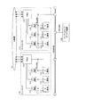
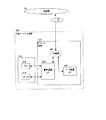
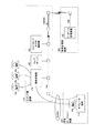
図1は、本願発明が適用された第1実施形態の構成を示すブロック図である。 FIG. 1 is a block diagram showing the configuration of the first embodiment to which the present invention is applied.
この図において2つのコールセンタ110は、いずれも、プレディクティブ・ダイヤラ装置130を用いたアウトバウンド業務が可能になっている。コールセンタ110は2つに限定されるものではなく、これ以上設けてもよい。
In this figure, the two
又、これらコールセンタ110は、いずれも、プレディクティブ・ダイヤラ装置130とは異なる拠点に設けられている。従って、いずれもリモート・エージェントになっている。
Further, all of these
あるいは、プレディクティブ・ダイヤラ装置130は、いずれかのコールセンタ110と同一の拠点に併せて設けるようにしてもよい。この場合、該コールセンタ110以外がリモート・エージェントになる。
Alternatively, the
この図において、コールセンタ110においては、電話機112及びオペレータ端末114は、オペレータ毎に配置されている。電話機112は、PBX116を経由して公衆網101に接続されている。電話機112は公衆網101により顧客の電話機に接続される。又、オペレータ端末114は、例えばパーソナル・コンピュータによって実現することも可能である。
In this figure, in the
又、この図において□印は、ネットワーク間を接続する接続装置である。すべてのオペレータ端末114又PBX116は、それぞれのコールセンタ110に敷設されているLAN(Local Area Network)18に接続されている。又、いずれのLAN118も上述の接続装置により、WAN150に接続されている。
Further, in this figure, □ indicates a connection device for connecting networks. All
従って、プレディクティブ・ダイヤラ装置130は、WAN150及び個々のコールセンタ110のLAN118を経由して、PBX116と情報の授受が可能になっている。具体的にはプレディクティブ・ダイヤラ装置130は、必要な情報をPBX116から得ることができる。又プレディクティブ・ダイヤラ装置130は、予め定められている命令情報をPBX116に送ることができ、これによりPBX116の動作を制御することができる。
Therefore, the
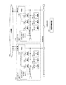
図2は、本実施形態で用いるプレディクティブ・ダイヤラ装置130の構成を示すブロック図である。
FIG. 2 is a block diagram showing a configuration of the
図示されるようにプレディクティブ・ダイヤラ装置130は、プレディクティブ・ダイヤラ制御部131と、データベース管理装置140とを有している。又プレディクティブ・ダイヤラ制御部131は、CTI(Computer Telephony Integration)制御装置33と、ペーシング制御装置135と、管理制御装置137とを含んでいる。
As illustrated, the
CTI制御装置133は、インバウンド業務で顧客からの着信があると、該着信をオペレータに分配するため、PBX116を制御する。この際、着信に係る必要な情報を、データベース管理装置140から該当するオペレータのオペレータ端末114に送る制御をする。
When there is an incoming call from a customer in an inbound service, the
更にCTI制御装置133は、アウトバウンド業務に関する機能を有している。即ちCTI制御装置133は、ペーシング制御装置135がプレディクティブ発信(予測発信)する際に、PBX116の発信におけるダイヤルなどの制御をする。又、このようなプレディクティブ発信に際して、発信すべき顧客のリストを含む情報は、データベース管理装置140からダイヤル時に逐次得る。
Furthermore, the
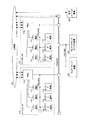
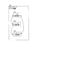
図3は、本願発明が適用された第2実施形態の構成を示すブロック図である。 FIG. 3 is a block diagram showing the configuration of the second embodiment to which the present invention is applied.
本実施形態では、前述した第1実施形態に対して在宅エージェント装置200及びウェブ・サーバ装置142が追加されている。他については第1実施形態と同様である。
In the present embodiment, a
この図において2つのコールセンタ110は、いずれも、プレディクティブ・ダイヤラ装置130を用いたアウトバウンド業務が可能になっている。コールセンタ110は2つに限定されるものではなく、これ以上設けてもよい。
In this figure, the two
又、これらコールセンタ110は、いずれも、プレディクティブ・ダイヤラ装置130とは異なる拠点に設けられている。従って、いずれもリモート・エージェントになっている。
Further, all of these
あるいは、プレディクティブ・ダイヤラ装置130は、いずれかのコールセンタ110と同一の拠点に併せて設けるようにしてもよい。この場合、該コールセンタ110以外がリモート・エージェントになる。
Alternatively, the
更には本実施形態では、在宅エージェント装置200は、リモート・エージェントの一種であり、在宅勤務者など基本的に1人のオペレータをリモート・オペレータとしている。しかしながら、数人を対象にするようにしてもよい。
Furthermore, in this embodiment, the
又、本実施形態の在宅エージェント装置200が有するオペレータ端末114は、いわゆるブラウザ・プログラムを利用している。例えば米国マイクロソフト社製の「インターネット・エクスプローラー」などのブラウザ・プログラムを利用している。又、該オペレータ端末114では、ログイン操作、及び前記顧客情報の表示に用いるプログラムを内蔵していない。これらプログラムは、その実行時にその都度、管理制御装置側のウェブ・サーバ装置142からダウンロードするようにしている。従って、在宅エージェント装置200側は、これらプログラムを保管する例えばハードディスク装置の容量が不要となるだけでなく、これらプログラムの更新などの管理をする必要がない。
The
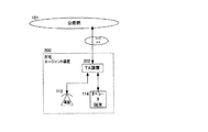
図4は、在宅エージェント装置200の第1例の構成を示すブロック図である。
FIG. 4 is a block diagram showing a configuration of a first example of the
第1例の在宅エージェント装置200は、オペレータが利用する電話機112及びオペレータ端末114に加え、TA(Terminal Adapter)装置202を有している。該TA装置202は、国内の通信事業者であるNTT(登録商標)が提供しているINS64によって公衆網101に接続するための接続装置である。この第1例の在宅エージェント装置200においては、電話機112の公衆網101による通話は、TA装置202を利用している。又、オペレータ端末114は、TA装置202により公衆網101を経由して所定のアクセスポイントに接続するなどして、WAN150に接続する。このようなTA装置202を用いるオペレータ端末114のWAN150に対する接続は、インターネットを経由して行ってもよい。
The
図5は、在宅エージェント装置200の第2例の構成を示すブロック図である。
FIG. 5 is a block diagram showing the configuration of the second example of the
第2例の在宅エージェント装置200は、オペレータが利用する電話機112及びオペレータ端末114に加え、TA装置202を有している。この第2例の在宅エージェント装置200においてオペレータ端末114は、第2例の在宅エージェント装置200と同様に、TA装置202により公衆網101を経由して所定のアクセスポイントに接続するなどして、WAN150に接続する。しかしながら、第2例の在宅エージェント装置200では、電話機112の公衆網101による通話は、TA装置202を利用せず公衆網101に直接接続して行う。
The
図6は、在宅エージェント装置200の第3例の構成を示すブロック図である。
FIG. 6 is a block diagram showing the configuration of the third example of the
第3例の在宅エージェント装置200では、オペレータ端末114内にTA装置202が設けられている。該オペレータ端末114は、例えばパーソナル・コンピュータによって実現することも可能である。又、該TA装置202を利用したオペレータ端末114のデータ通信に利用するデータ通信インタフェイス装置220に加えて、電話機112を実現するための音声通話インタフェイス装置210を有している。オペレータは、ヘッドフォンのようにオペレータ(利用者)の頭部に装着するヘッドセット212として構成されているマイク装置214及びスピーカ装置216を利用し、マイク装置214により送話し、スピーカ装置216により受話するようにして、顧客に対して通話する。又、このような第3例の在宅エージェント装置200においては、前述の第1例の在宅エージェント装置200と同様に、オペレータが利用する電話機の公衆網101による通話、及びオペレータ端末114のWAN150に対する接続は、TA装置202を利用している。
In the
図7は、本願発明が適用された第3実施形態の構成を示すブロック図である。 FIG. 7 is a block diagram showing the configuration of the third embodiment to which the present invention is applied.
本実施形態では、前述した第1実施形態が有しているプレディクティブ・ダイヤラ装置130の一部分がプレディクティブ・ダイヤラ・エンジン146として構成され、それぞれのコールセンタ110に設けられている。
In the present embodiment, a part of the
図8は、本実施形態で用いるプレディクティブ・ダイヤラ・エンジン146の構成を示すブロック図である。
FIG. 8 is a block diagram showing the configuration of the
図示されるように、プレディクティブ・ダイヤラ装置130が有しているものの内で管理制御装置137以外の、CTI制御装置133、ペーシング制御装置135、及びデータベース管理装置140により、プレディクティブ・ダイヤラ・エンジン146を構成している。管理制御装置137については、プレディクティブ・ダイヤラ・エンジン146とは別に設ける。
As shown in the figure, the
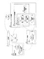
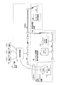
図9は、本願発明が適用された第4実施形態の構成を示すブロック図である。 FIG. 9 is a block diagram showing the configuration of the fourth embodiment to which the present invention is applied.
本実施形態では、前述した第3実施形態に対して在宅エージェント装置200及びウェブ・サーバ装置142が追加されている。該ウェブ・サーバ装置142及び管理制御装置137は、LAN152に接続されている。又LAN152はWAN150に接続されている。他については第3実施形態と同様である。
In the present embodiment, a
なお、ウェブ・サーバ装置142は管理制御装置137と共に設置することで、これらの管理の一元化を図ることができる。例えば、これらを制御するプログラムの更新や、ウェブ・サーバ装置142に設けるオペレータ端末114にダウンロードするプログラムの更新など、種々の管理の一元化を図ることができる。しかしながら、図9において符号42の破線で図示するように、ウェブ・サーバ装置142は、コールセンタ110側に設けるようにしてもよい。
The
在宅エージェント装置200は、リモート・エージェントの一種であり、在宅勤務者など基本的に1人のオペレータをリモート・オペレータとしている。しかしながら、数人を対象にするようにしてもよい。
The
又、本実施形態の在宅エージェント装置200が有するオペレータ端末114は、いわゆるブラウザ・プログラムを利用している。例えば米国マイクロソフト社製の「インターネット・エクスプローラー」などのブラウザ・プログラムを利用している。又、該オペレータ端末114では、ログイン操作、及び前記顧客情報の表示に用いるプログラムを内蔵していない。これらプログラムは、その実行時にその都度、管理制御装置側のウェブ・サーバ装置142からダウンロードするようにしている。従って、在宅エージェント装置200側は、これらプログラムを保管する例えばハードディスク装置の容量が不要となるだけでなく、これらプログラムの更新などの管理をする必要がない。
The
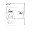
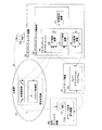
図10は、前述した第1〜第4実施形態の作用を説明するための信号の流れを示すブロック図である。 FIG. 10 is a block diagram showing a signal flow for explaining the operation of the first to fourth embodiments described above.
この図において、一点差線は、顧客103と対応するための音声による通話の接続を示す。又、二点差線は、このような通話を確立したり維持したり、又このような通話中に顧客103に関する情報をオペレータに提供するための、制御に関する信号の流れを示す。又、オペレータ端末受付画面114aは、オペレータ端末114に表示される画面であり、後述する図12や図13のような画面である。
In this figure, a one-dot chain line indicates a voice call connection for dealing with the
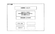
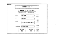
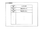
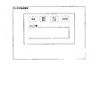
次に、図11は、これら実施形態におけるログイン画面を示す線図である。図12は、これら実施形態における第1の受付画面を示す線図である。図13は、これら実施形態における第2の受付画面を示す線図である。図14は、これら実施形態におけるコンタクト履歴画面を示す線図である。図15は、これら実施形態におけるコンタクト結果画面を示す線図である。 Next, FIG. 11 is a diagram showing a login screen in these embodiments. FIG. 12 is a diagram showing a first reception screen in these embodiments. FIG. 13 is a diagram showing a second reception screen in these embodiments. FIG. 14 is a diagram showing a contact history screen in these embodiments. FIG. 15 is a diagram showing a contact result screen in these embodiments.
これら図11〜図15において、一点鎖線の矩形は、ポインティング入力装置であるマウスによる位置指示及びクリック操作によりプッシュ操作できる、画面上の押しボタンの表示である。又、破線の矩形は、入力する文字を表示する領域である。あるいは、破線の矩形は、顧客に関する情報など、既に入力されている情報を表示する領域である。なお、オペレータ端末114には、オペレータが利用する入力手段として、マウス及びキーボードが接続されている。
11 to 15, a dashed-dotted line rectangle is a display of push buttons on the screen that can be pushed by a position instruction and a click operation by a mouse that is a pointing input device. A broken-line rectangle is an area for displaying input characters. Or the rectangle of a broken line is an area | region which displays the information already input, such as the information regarding a customer. Note that a mouse and a keyboard are connected to the
以下において、これら図10〜図15を用い、第1〜第4実施形態の作用を説明する。 Hereinafter, the operation of the first to fourth embodiments will be described with reference to FIGS.
まず、これらの実施形態において、在宅エージェント装置200のオペレータ端末114によるログインでは、以下に列挙する事項を、列挙する順に行う。
First, in these embodiments, in the login by the
A.在宅エージェントのログイン処理。 A. Home agent login process.
A1.在宅エージェント装置200のオペレータ(リモート・オペレータ)は、該在宅エージェント装置200のオペレータ端末114において、ブラウザ・プログラムを起動する。そうして、ウェブ・サーバ装置142にアクセスする。又、図11に図示するログイン画面をブラウザ・プログラムにおいて表示すべく操作することで、ウェブ・サーバ装置142にあるウェブ・アプリケーション・プログラム144の1つである、該ログイン画面を表示するためのプログラムをダウンロードし、その後起動する。なお、このようなオペレータ端末114のウェブ・サーバ装置142に対するアクセスは、インターネットを経由して行ってもよく、あるいは他のWAN150の経路によって行ってもよい。
A1. An operator (remote operator) of the
A2.そうして、在宅エージェント装置200のオペレータは、オペレータ端末114に表示された図11に図示する画面により、インターネット経由で、あるいは他のWAN150の経路によって、プレディクティブ・ダイヤラ制御部131にログイン要求を行う。
A2. Then, the operator of the
A3.プレディクティブ・ダイヤラ制御部131は、ログイン要求を行った在宅エージェント装置200を登録する。
A3. The predictive
A4.ログイン要求を行った在宅エージェント装置200のオペレータ端末114には、インターネット経由で、あるいは他のWAN150の経路によって、図12や図13に図示するような受付画面を表示するため、ウェブ・サーバ装置142にあるウェブ・アプリケーション・プログラム144の1つである、該受付画面を表示するためのプログラムを起動する。そうして該受付画面が該当するオペレータ端末114に表示される。
A4. The
次に、これらの実施形態において、在宅エージェント装置200に関するプレディクティブ発信処理では、以下に列挙する事項を、列挙する順に行う。
Next, in these embodiments, in the predictive call processing relating to the
B.プレディクティブ発信処理。 B. Predictive call processing.
B1.プレディクティブ・ダイヤラ制御部131はデータベース管理装置140に対して発信データを要求する。
B1. The predictive
B2.データベース管理装置140はプレディクティブ・ダイヤラ制御部131から要求された発信データを、該プレディクティブ・ダイヤラ制御部131へ送信する。
B2. The
B3.プレディクティブ・ダイヤラ制御部131はPBX116に対して発信命令を発行する。
B3. Predictive
更に、これらの実施形態において、在宅エージェント装置200及び顧客103の接続処理では、以下に列挙する事項を、列挙する順に行う。
Furthermore, in these embodiments, in the connection process between the
C.在宅エージェントとの接続処理。 C. Connection process with home agent.
C1.PBX116は顧客103が応答した呼を、在宅エージェント装置200の電話機112に転送する。
C1. The
C2.PBX116がCTI制御装置133に応答情報を送信する。
C2. The
C3.CTI制御装置133はデータベース管理装置140に応答情報を送信する。
C3. The
C4.データベース管理装置140は該応答情報を元にして、該データベース管理装置140により管理されるデータベースを検索して、顧客情報を得る。そうして、インターネット経由で、あるいは他のWAN150の経路によって、ウェブ・サーバ装置142にあるウェブ・アプリケーション・プログラム144の1つである、該受付画面を表示するためのプログラムにより、顧客103の応答状態、及び顧客情報を通知する。
C4. Based on the response information, the
C5.在宅エージェント装置200側は、インターネット経由で、あるいは他のWAN150の経路によって、図13に図示するように、顧客情報を受付画面に表示させることができる。更には所定の操作をオペレータがすることで、図14や図15に図示されるような画面を、そのオペレータのオペレータ端末114に表示することができる。図12や図13において一点鎖線で図示される、『コンタクト履歴』のボタンを押下することで図14の画面を表示することができ、『コンタクト結果』のボタンを押下することで図15の画面を表示することができる。
C5. The
以上のようにこれら実施形態によれば、本願発明を効果的に適用することができる。従って、アウトバウンド業務を対象とする場合にも、顧客に応対するコールセンタのオペレータを遠隔地にも配置できるようにし、コールセンタの運営効率の向上や運営費の削減を図ることができる。 As described above, according to these embodiments, the present invention can be effectively applied. Therefore, even when an outbound business is targeted, it is possible to arrange a call center operator who responds to a customer at a remote location, and to improve the operation efficiency of the call center and reduce the operation cost.
図16は、本願発明が適用された第5実施形態の構成を示すブロック図である。 FIG. 16 is a block diagram showing the configuration of the fifth embodiment to which the present invention is applied.
本実施形態において、又後述する第6及び第7実施形態において、キャリア側設備170は、公衆網に含まれる。又、キャリア側設備170の局側交換機172は、公衆網における回線の接続の交換をするものである。
In the present embodiment, and in the sixth and seventh embodiments described later, the carrier-
本実施形態では、公衆網内に含まれるキャリア側設備170において、前述したプレディクティブ・ダイヤラ装置130に関する機能の部分を構成するようにしている。即ち、キャリア側設備170において、プレディクティブ・ダイヤラ制御部131及びデータベース管理装置140を構成すると共に、ウェブ・サーバ装置142を構成するようにしている。
In the present embodiment, the carrier-
なお、キャリア側設備170において、局側交換機172その他を接続しているネットワーク154は、LANなどの所定のネットワークである。
In the
図17は、本願発明が適用された第6実施形態の構成を示すブロック図である。 FIG. 17 is a block diagram showing the configuration of the sixth embodiment to which the present invention is applied.
本実施形態では、公衆網内に含まれるキャリア側設備170において、前述したプレディクティブ・ダイヤラ装置130に関する機能の部分を構成するようにしている。即ち、キャリア側設備170において、プレディクティブ・ダイヤラ制御部131を構成すると共に、ウェブ・サーバ装置142を構成するようにしている。又、データベース管理装置140については、利用企業側設備180に設けるようにしている。
In the present embodiment, the carrier-
ここで、上述の利用企業とは、アウトバウンド業務利用企業であり、アウトバウンド業務により顧客に対して種々のサービスを提供する企業である。 Here, the above-mentioned user enterprises are enterprises that use outbound business, and are enterprises that provide various services to customers through outbound business.
本実施形態では、データベース管理装置140を利用企業側設備180に設けることで、利用企業は、データベース管理装置140を容易に更新することができる。例えば、プレディクティブ発信に際して、発信すべき顧客103のリストを含むデータベース管理装置140に格納された情報なども、容易に更新することができる。
In the present embodiment, by providing the
なお、利用企業側設備180において、データベース管理装置140その他を接続しているネットワーク156は、LANなどの所定のネットワークである。
In the user
図18は、本願発明が適用された第7実施形態の構成を示すブロック図である。 FIG. 18 is a block diagram showing the configuration of the seventh embodiment to which the present invention is applied.
本実施形態においては、前述したようなネットワーク・サービスを利用し、コールセンタ運営専門会社側設備182から、局側交換機172における配信を制御するようにしている。即ち、プレディクティブ発信を行って顧客103の応答があった呼を、適当な在宅エージェント装置200の電話機112に配信することを、このようなネットワーク・サービスを利用して、コールセンタ運営専門会社側設備182のプレディクティブ・ダイヤラ制御部131によって行っている。
In the present embodiment, the network service as described above is used to control the distribution in the
ここで、上述のコールセンタ運営専門会社とは、アウトバウンド業務の委託を受け、これらの業務を行うものである。該コールセンタ運営専門会社は、このような業務を行うための設備やオペレータを擁し、前述のアウトバウンド業務利用企業が顧客に対して提供しようとする種々のサービスを代行などする。 Here, the above-mentioned call center management specialist company is entrusted with outbound work and performs these work. The call center management specialist company has facilities and operators for performing such operations, and the above-described outbound business user company performs various services on behalf of customers.
本実施形態では、コールセンタ運営専門会社側設備182において、前述したプレディクティブ・ダイヤラ装置130に関する機能の部分を構成するようにしている。即ち、コールセンタ運営専門会社側設備182において、プレディクティブ・ダイヤラ制御部131を構成すると共に、ウェブ・サーバ装置142を構成するようにしている。又、データベース管理装置140については、利用企業側設備180に設けるようにしている。
In the present embodiment, the function relating to the
本実施形態では、データベース管理装置140を利用企業側設備180に設けることで、利用企業は、データベース管理装置140を容易に更新することができる。例えば、プレディクティブ発信に際して、発信すべき顧客103のリストを含むデータベース管理装置140に格納された情報なども、容易に更新することができる。
In the present embodiment, by providing the
更に、アウトバウンド業務やインバウンド業務を提供するための構成は、コールセンタ運営専門会社側設備182に備えるようにしている。従って、コールセンタ運営専門会社側が、そのノウハウを活かして、これら業務の設備の保守をすることができる。
Furthermore, the configuration for providing the outbound business and the inbound business is provided in the call center management specialized
なお、コールセンタ運営専門会社側設備182において、プレディクティブ・ダイヤラ制御部131その他を接続しているネットワーク158は、LANなどの所定のネットワークである。
Note that the
又、該ネットワーク158は、キャリア側設備170における前述したSCPと称するノードに接続することで、前述したようなネットワーク・サービスにより、局側交換機172にアクセスしている。該アクセスによってコールセンタ運営専門会社側設備182のプレディクティブ・ダイヤラ制御部131は、局側交換機172の発信やスイッチングの制御を行っている。
Further, the
図19は、前述した第5〜第7実施形態の作用を説明するための信号の流れを示すブロック図である。 FIG. 19 is a block diagram showing a signal flow for explaining the operation of the fifth to seventh embodiments.
この図に示すように局側交換機172は、発信制御部174と、スイッチング制御部176とを有している。これら発信制御部174及びスイッチング制御部176は、前述したような公衆網101に関するネットワーク・サービスにより、プレディクティブ・ダイヤラ装置130側から制御される。
As shown in this figure, the
このようにネットワーク・サービスにより制御され、発信制御部174は、在宅エージェント装置200の電話機112の回線への発信をし、図中一点鎖線J1で示すように、該回線を待機状態にする。又、このようにネットワーク・サービスにより制御され、発信制御部174は、顧客103の電話機の回線への発信をし、図中一点鎖線J2で示すように、該回線を待機状態にする。そうして、スイッチング制御部176は、このようなネットワーク・サービスにより、図中一点鎖線J3で示すように、これら待機状態の回線同士を接続する。
In this way, controlled by the network service, the transmission control unit 174 makes a call to the line of the
以下において、この図19、又前述した図11〜図15を用い、第5〜第7実施形態の作用を説明する。 Hereinafter, the operation of the fifth to seventh embodiments will be described with reference to FIG. 19 and FIGS. 11 to 15 described above.
まず、これらの実施形態において、在宅エージェント装置200のオペレータ端末114によるログインでは、以下に列挙する事項を、列挙する順に行う。
First, in these embodiments, in the login by the
D.在宅エージェントのログイン処理。 D. Home agent login process.
D1.在宅エージェント装置200のオペレータ(リモート・オペレータ)は、該在宅エージェント装置200のオペレータ端末114において、ブラウザ・プログラムを起動する。そうして、ウェブ・サーバ装置142にアクセスする。又、図11に図示するログイン画面をブラウザ・プログラムにおいて表示すべく操作することで、ウェブ・サーバ装置142にあるウェブ・アプリケーション・プログラム144の1つである、該ログイン画面を表示するためのプログラムをダウンロードし、その後起動する。なお、このようなオペレータ端末114のウェブ・サーバ装置142に対するアクセスは、インターネットを経由して行ってもよく、あるいは他のWAN150の経路によって行ってもよい。
D1. An operator (remote operator) of the
D2.そうして、在宅エージェント装置200のオペレータは、オペレータ端末114に表示された図11に図示する画面により、インターネット経由で、あるいは他のWAN150の経路によって、プレディクティブ・ダイヤラ制御部131にログイン要求を行う。
D2. Then, the operator of the
D3.プレディクティブ・ダイヤラ制御部131は、ログイン要求を行った在宅エージェント装置200の電話機112に繋がる通信回線と、局側交換機172を接続状態にする。
D3. The predictive
D4.ログイン要求を行った在宅エージェント装置200のオペレータ端末114には、インターネット経由で、あるいは他のWAN150の経路によって、図12や図13に図示するような受付画面を表示するため、ウェブ・サーバ装置142にあるウェブ・アプリケーション・プログラム144の1つである、該受付画面を表示するためのプログラムを起動する。そうして該受付画面が該当するオペレータ端末114に表示される。
D4. The
次に、これらの実施形態において、在宅エージェント装置200に関するプレディクティブ発信処理では、以下に列挙する事項を、列挙する順に行う。
Next, in these embodiments, in the predictive call processing relating to the
E.プレディクティブ発信処理。 E. Predictive call processing.
E1.プレディクティブ・ダイヤラ制御部131はデータベース管理装置140に対して発信データを要求する。
E1. The predictive
E2.データベース管理装置140はプレディクティブ・ダイヤラ制御部131から要求された発信データを、該プレディクティブ・ダイヤラ制御部131へ送信する。
E2. The
E3.プレディクティブ・ダイヤラ制御部131は局側交換機172に対して発信命令を発行する。
E3. The predictive
更に、これらの実施形態において、在宅エージェント装置200及び顧客103の接続処理では、以下に列挙する事項を、列挙する順に行う。
Furthermore, in these embodiments, in the connection process between the
F.在宅エージェントとの接続処理。 F. Connection process with home agent.
F1.局側交換機172は顧客103が応答した呼を、在宅エージェント装置200の電話機112に繋がる通信回線に分配する。このとき、顧客103と在宅エージェント装置200の電話機112は通話状態になる。
F1. The
F2.局側交換機172がプレディクティブ・ダイヤラ制御部131内部のCTI制御装置133に応答情報を送信する。
F2. The
F3.CTI制御装置133はデータベース管理装置140に応答情報を送信する。
F3. The
F4.データベース管理装置140は該応答情報を元にして、該データベース管理装置140により管理されるデータベースを検索して、顧客情報を得る。そうして、インターネット経由で、あるいは他のWAN150の経路によって、ウェブ・サーバ装置142にあるウェブ・アプリケーション・プログラム144の1つである、該受付画面を表示するためのプログラムにより、顧客103の応答状態、及び顧客情報を通知する。
F4. Based on the response information, the
F5.在宅エージェント装置200側においてオペレータは、顧客103との接続を局側交換機172からの接続音で確認した後、インターネット経由で、あるいは他のWAN150の経路によって、図13に図示するように、顧客情報を受付画面に表示させることができる。更には所定の操作をオペレータがすることで、図14や図15に図示されるような画面を、そのオペレータのオペレータ端末114に表示することができる。
F5. On the
以上のようにこれら実施形態によれば、本願発明を効果的に適用することができる。従って、アウトバウンド業務を対象とする場合にも、顧客103に応対するコールセンタのオペレータを遠隔地にも配置できるようにし、コールセンタの運営効率の向上や運営費の削減を図ることができる。
As described above, according to these embodiments, the present invention can be effectively applied. Therefore, even when an outbound business is targeted, it is possible to place a call center operator who responds to the
本発明によれば、効率よくコールセンタ運営ができ、その運営費の削減などが可能となる。 According to the present invention, the call center can be efficiently operated, and the operation cost can be reduced.
101…公衆網
103…顧客
110…コールセンタ
112…電話機
114…オペレータ端末
116…PBX
118、152…LAN
130…プレディクティブ・ダイヤラ装置
131…プレディクティブ・ダイヤラ制御部
133…CTI制御装置
135…ペーシング制御装置
137…管理制御装置
140…データベース管理装置
142…ウェブ・サーバ装置
144…ウェブ・アプリケーション・プログラム
146…プレディクティブ・ダイヤラ・エンジン
150…WAN
154、156、158…ネットワーク
170…キャリア側設備
172…局側交換機
174…発信制御部
176…スイッチング制御部
180…利用企業側設備
182…コールセンタ運営専門会社側設備
200…在宅エージェント装置
202…TA装置
210…音声通話インタフェイス装置
212…ヘッドセット
214…マイク装置
216…スピーカ装置
220…データ通信インタフェイス装置
DESCRIPTION OF
118, 152 ... LAN
DESCRIPTION OF
154, 156, 158 ...
Claims (2)
広域ネットワークを経由して1箇所の自動ダイヤラ装置から当該複数のコールセンタ毎に同時に発信を行うことができるリモートコールセンタ装置。 A private branch exchange for each call center, a telephone connected to the private branch exchange, and an operator terminal operated by a human operator are prepared,
A remote call center device capable of simultaneously making a call to each of the plurality of call centers from a single automatic dialer device via a wide area network.
Priority Applications (1)
| Application Number | Priority Date | Filing Date | Title |
|---|---|---|---|
| JP2005148806A JP4313783B2 (en) | 1999-12-21 | 2005-05-20 | Call center equipment |
Applications Claiming Priority (3)
| Application Number | Priority Date | Filing Date | Title |
|---|---|---|---|
| JP36338799 | 1999-12-21 | ||
| JP2000132063 | 2000-05-01 | ||
| JP2005148806A JP4313783B2 (en) | 1999-12-21 | 2005-05-20 | Call center equipment |
Related Parent Applications (1)
| Application Number | Title | Priority Date | Filing Date |
|---|---|---|---|
| JP2001547834A Division JP3770832B2 (en) | 1999-12-21 | 2000-08-03 | Call center operation system |
Publications (2)
| Publication Number | Publication Date |
|---|---|
| JP2005295592A true JP2005295592A (en) | 2005-10-20 |
| JP4313783B2 JP4313783B2 (en) | 2009-08-12 |
Family
ID=35327933
Family Applications (1)
| Application Number | Title | Priority Date | Filing Date |
|---|---|---|---|
| JP2005148806A Expired - Fee Related JP4313783B2 (en) | 1999-12-21 | 2005-05-20 | Call center equipment |
Country Status (1)
| Country | Link |
|---|---|
| JP (1) | JP4313783B2 (en) |
Cited By (1)
| Publication number | Priority date | Publication date | Assignee | Title |
|---|---|---|---|---|
| WO2019162840A1 (en) * | 2018-02-20 | 2019-08-29 | T2W Connect Ipco Pty Ltd | Telephony software control via web application |
-
2005
- 2005-05-20 JP JP2005148806A patent/JP4313783B2/en not_active Expired - Fee Related
Cited By (1)
| Publication number | Priority date | Publication date | Assignee | Title |
|---|---|---|---|---|
| WO2019162840A1 (en) * | 2018-02-20 | 2019-08-29 | T2W Connect Ipco Pty Ltd | Telephony software control via web application |
Also Published As
| Publication number | Publication date |
|---|---|
| JP4313783B2 (en) | 2009-08-12 |
Similar Documents
| Publication | Publication Date | Title |
|---|---|---|
| US7136475B1 (en) | Call Management system with call control from user workstation computers | |
| AU716368B2 (en) | Telecommunication management system and user interface | |
| US8199899B2 (en) | Call management system with call control from user workstation computers | |
| JP4125806B2 (en) | Communication routing apparatus and method | |
| US20070127687A1 (en) | Call center operations system | |
| JP4385110B2 (en) | Call center system, incoming call distribution device, incoming call distribution method, program | |
| JP4444763B2 (en) | System and method for enhanced computer telephony integration and interaction | |
| US20100014511A1 (en) | Call centers for providing customer services in a telecommunications network | |
| JP2005160095A (en) | System for providing interoperability of proprietary enterprise communication network with cellular communication network | |
| JP3801447B2 (en) | Call center operation statistics collection system | |
| WO2006109883A1 (en) | Telephone control apparatus, telephone control method, telephone control program, telephone terminal, telephone calling method, telephone calling program, and telephone control system | |
| JP4313783B2 (en) | Call center equipment | |
| JP4840101B2 (en) | IP call center system | |
| JP4313782B2 (en) | Call center operation method and apparatus | |
| JP3941904B2 (en) | Switch control system | |
| JP3758978B2 (en) | Inbound bridge system | |
| US20070116229A1 (en) | Method for forwarding a call to a call number that is assigned to the originally dialed number by means of a directory system | |
| JP3155908B2 (en) | PBX-computer cooperation system, PBX and cooperation method therefor | |
| JP7140429B1 (en) | Server device, telephone connection method and telephone connection program | |
| JP5267625B2 (en) | IP call center system and control method | |
| KR100612441B1 (en) | The system and method for stabilizied call distribution in CTI system | |
| JP4230827B2 (en) | How to select a predictive calling operator | |
| US7123712B1 (en) | Computer telephony server with improved flexibility | |
| KR20030063064A (en) | Method and System for Providing a CTI Service for Extention Terminal by Using an IP-PBX | |
| JP2023142766A (en) | telephone system |
Legal Events
| Date | Code | Title | Description |
|---|---|---|---|
| A621 | Written request for application examination |
Free format text: JAPANESE INTERMEDIATE CODE: A621 Effective date: 20060314 |
|
| A131 | Notification of reasons for refusal |
Free format text: JAPANESE INTERMEDIATE CODE: A131 Effective date: 20070904 |
|
| A521 | Written amendment |
Free format text: JAPANESE INTERMEDIATE CODE: A523 Effective date: 20071101 |
|
| A131 | Notification of reasons for refusal |
Free format text: JAPANESE INTERMEDIATE CODE: A131 Effective date: 20080819 |
|
| A521 | Written amendment |
Free format text: JAPANESE INTERMEDIATE CODE: A523 Effective date: 20081014 |
|
| TRDD | Decision of grant or rejection written | ||
| A01 | Written decision to grant a patent or to grant a registration (utility model) |
Free format text: JAPANESE INTERMEDIATE CODE: A01 Effective date: 20090512 |
|
| A01 | Written decision to grant a patent or to grant a registration (utility model) |
Free format text: JAPANESE INTERMEDIATE CODE: A01 |
|
| A61 | First payment of annual fees (during grant procedure) |
Free format text: JAPANESE INTERMEDIATE CODE: A61 Effective date: 20090515 |
|
| FPAY | Renewal fee payment (prs date is renewal date of database) |
Free format text: PAYMENT UNTIL: 20120522 Year of fee payment: 3 |
|
| R150 | Certificate of patent (=grant) or registration of utility model |
Free format text: JAPANESE INTERMEDIATE CODE: R150 |
|
| FPAY | Renewal fee payment (prs date is renewal date of database) |
Free format text: PAYMENT UNTIL: 20120522 Year of fee payment: 3 |
|
| FPAY | Renewal fee payment (prs date is renewal date of database) |
Free format text: PAYMENT UNTIL: 20130522 Year of fee payment: 4 |
|
| FPAY | Renewal fee payment (prs date is renewal date of database) |
Free format text: PAYMENT UNTIL: 20140522 Year of fee payment: 5 |
|
| LAPS | Cancellation because of no payment of annual fees |