JP2005293595A - Multi-path redundant storage system architecture and method - Google Patents
Multi-path redundant storage system architecture and method Download PDFInfo
- Publication number
- JP2005293595A JP2005293595A JP2005105966A JP2005105966A JP2005293595A JP 2005293595 A JP2005293595 A JP 2005293595A JP 2005105966 A JP2005105966 A JP 2005105966A JP 2005105966 A JP2005105966 A JP 2005105966A JP 2005293595 A JP2005293595 A JP 2005293595A
- Authority
- JP
- Japan
- Prior art keywords
- data storage
- disk
- controller
- storage devices
- storage system
- Prior art date
- Legal status (The legal status is an assumption and is not a legal conclusion. Google has not performed a legal analysis and makes no representation as to the accuracy of the status listed.)
- Pending
Links
- 238000000034 method Methods 0.000 title claims abstract description 26
- 238000003860 storage Methods 0.000 title claims description 63
- 238000013500 data storage Methods 0.000 claims abstract description 162
- 230000000712 assembly Effects 0.000 claims abstract description 25
- 238000000429 assembly Methods 0.000 claims abstract description 25
- 230000009977 dual effect Effects 0.000 claims description 25
- 238000004590 computer program Methods 0.000 claims description 12
- 238000004891 communication Methods 0.000 claims description 11
- 238000002955 isolation Methods 0.000 abstract description 4
- 238000012360 testing method Methods 0.000 description 33
- 238000012545 processing Methods 0.000 description 9
- 230000008569 process Effects 0.000 description 7
- 239000000835 fiber Substances 0.000 description 5
- 230000004044 response Effects 0.000 description 4
- 238000012546 transfer Methods 0.000 description 3
- 238000006243 chemical reaction Methods 0.000 description 2
- 238000010276 construction Methods 0.000 description 2
- 238000010586 diagram Methods 0.000 description 2
- 230000007613 environmental effect Effects 0.000 description 2
- 230000007257 malfunction Effects 0.000 description 2
- 238000012986 modification Methods 0.000 description 2
- 230000004048 modification Effects 0.000 description 2
- 230000003287 optical effect Effects 0.000 description 2
- 230000001105 regulatory effect Effects 0.000 description 2
- XUIMIQQOPSSXEZ-UHFFFAOYSA-N Silicon Chemical compound [Si] XUIMIQQOPSSXEZ-UHFFFAOYSA-N 0.000 description 1
- 238000003491 array Methods 0.000 description 1
- 230000008901 benefit Effects 0.000 description 1
- 230000008859 change Effects 0.000 description 1
- 239000002131 composite material Substances 0.000 description 1
- 238000013461 design Methods 0.000 description 1
- 238000005516 engineering process Methods 0.000 description 1
- 239000004744 fabric Substances 0.000 description 1
- 230000005669 field effect Effects 0.000 description 1
- 238000003780 insertion Methods 0.000 description 1
- 230000037431 insertion Effects 0.000 description 1
- 238000009434 installation Methods 0.000 description 1
- 238000012423 maintenance Methods 0.000 description 1
- 238000012544 monitoring process Methods 0.000 description 1
- 238000005192 partition Methods 0.000 description 1
- 230000005855 radiation Effects 0.000 description 1
- 230000008439 repair process Effects 0.000 description 1
- 238000012552 review Methods 0.000 description 1
- 229910052710 silicon Inorganic materials 0.000 description 1
- 239000010703 silicon Substances 0.000 description 1
- 239000007787 solid Substances 0.000 description 1
- 239000000126 substance Substances 0.000 description 1
- 238000006467 substitution reaction Methods 0.000 description 1
- 230000035899 viability Effects 0.000 description 1
Images


Classifications
-
- G—PHYSICS
- G06—COMPUTING; CALCULATING OR COUNTING
- G06F—ELECTRIC DIGITAL DATA PROCESSING
- G06F11/00—Error detection; Error correction; Monitoring
- G06F11/07—Responding to the occurrence of a fault, e.g. fault tolerance
- G06F11/16—Error detection or correction of the data by redundancy in hardware
- G06F11/20—Error detection or correction of the data by redundancy in hardware using active fault-masking, e.g. by switching out faulty elements or by switching in spare elements
- G06F11/2053—Error detection or correction of the data by redundancy in hardware using active fault-masking, e.g. by switching out faulty elements or by switching in spare elements where persistent mass storage functionality or persistent mass storage control functionality is redundant
- G06F11/2089—Redundant storage control functionality
-
- G—PHYSICS
- G06—COMPUTING; CALCULATING OR COUNTING
- G06F—ELECTRIC DIGITAL DATA PROCESSING
- G06F11/00—Error detection; Error correction; Monitoring
- G06F11/07—Responding to the occurrence of a fault, e.g. fault tolerance
- G06F11/08—Error detection or correction by redundancy in data representation, e.g. by using checking codes
- G06F11/10—Adding special bits or symbols to the coded information, e.g. parity check, casting out 9's or 11's
- G06F11/1076—Parity data used in redundant arrays of independent storages, e.g. in RAID systems
-
- G—PHYSICS
- G06—COMPUTING; CALCULATING OR COUNTING
- G06F—ELECTRIC DIGITAL DATA PROCESSING
- G06F11/00—Error detection; Error correction; Monitoring
- G06F11/07—Responding to the occurrence of a fault, e.g. fault tolerance
- G06F11/16—Error detection or correction of the data by redundancy in hardware
- G06F11/20—Error detection or correction of the data by redundancy in hardware using active fault-masking, e.g. by switching out faulty elements or by switching in spare elements
- G06F11/2002—Error detection or correction of the data by redundancy in hardware using active fault-masking, e.g. by switching out faulty elements or by switching in spare elements where interconnections or communication control functionality are redundant
- G06F11/2005—Error detection or correction of the data by redundancy in hardware using active fault-masking, e.g. by switching out faulty elements or by switching in spare elements where interconnections or communication control functionality are redundant using redundant communication controllers
-
- G—PHYSICS
- G06—COMPUTING; CALCULATING OR COUNTING
- G06F—ELECTRIC DIGITAL DATA PROCESSING
- G06F11/00—Error detection; Error correction; Monitoring
- G06F11/07—Responding to the occurrence of a fault, e.g. fault tolerance
- G06F11/16—Error detection or correction of the data by redundancy in hardware
- G06F11/20—Error detection or correction of the data by redundancy in hardware using active fault-masking, e.g. by switching out faulty elements or by switching in spare elements
- G06F11/2002—Error detection or correction of the data by redundancy in hardware using active fault-masking, e.g. by switching out faulty elements or by switching in spare elements where interconnections or communication control functionality are redundant
- G06F11/2007—Error detection or correction of the data by redundancy in hardware using active fault-masking, e.g. by switching out faulty elements or by switching in spare elements where interconnections or communication control functionality are redundant using redundant communication media
- G06F11/201—Error detection or correction of the data by redundancy in hardware using active fault-masking, e.g. by switching out faulty elements or by switching in spare elements where interconnections or communication control functionality are redundant using redundant communication media between storage system components
-
- G—PHYSICS
- G06—COMPUTING; CALCULATING OR COUNTING
- G06F—ELECTRIC DIGITAL DATA PROCESSING
- G06F11/00—Error detection; Error correction; Monitoring
- G06F11/07—Responding to the occurrence of a fault, e.g. fault tolerance
- G06F11/16—Error detection or correction of the data by redundancy in hardware
- G06F11/20—Error detection or correction of the data by redundancy in hardware using active fault-masking, e.g. by switching out faulty elements or by switching in spare elements
- G06F11/2053—Error detection or correction of the data by redundancy in hardware using active fault-masking, e.g. by switching out faulty elements or by switching in spare elements where persistent mass storage functionality or persistent mass storage control functionality is redundant
- G06F11/2094—Redundant storage or storage space
Landscapes
- Engineering & Computer Science (AREA)
- Theoretical Computer Science (AREA)
- Quality & Reliability (AREA)
- Physics & Mathematics (AREA)
- General Engineering & Computer Science (AREA)
- General Physics & Mathematics (AREA)
- Hardware Redundancy (AREA)
- Signal Processing For Digital Recording And Reproducing (AREA)
Abstract
Description
本発明は、概してデータ・ストーレジ・システムに関し、特にフォールト・トレラント・データ・ストーレジ・システムにおけるストーレジ・コンポーネントの相互接続システム及び方法に関する。 The present invention relates generally to data storage systems, and more particularly to a storage component interconnection system and method in a fault tolerant data storage system.
データ・ストーレジ・システムは、1以上のディスク・ドライブを1以上のディスク・コントローラに接続し、1以上のディスク・コントローラをホスト即ちネットワーク・インターフェースに接続してなるものでよい。例えばディスク・ドライブ、コントローラ、コネクタ及びワイヤリングのようなストーレジ・システムの各コンポーネントは、システムにおける潜在的な故障箇所である。例えばパーソナル・コンピュータのように、いくつかのシステムは、コントローラ、バス又はコネクタが故障した場合に、データに対するアクセス不能となる恐れがある。データに対するアクセスは、故障したコンポーネントを修理若しくは交換する、又はディスク・ドライブを他のシステムにインストールしてデータをアクセスしなければならないことがある。ディスク・ドライブの故障は、通常、記憶データの損失に至る。大規模のストーレジ・システムは、ドライブ故障の場合にデータを損失しないように、複数のドライブにまたがってデータを分配させるRAIDのような冗長な方法を採用することもできる。RAIDシステムにおいて、故障したドライブからのデータは、ミラー・ドライブからコピーされてもよく、又は動作しているドライブ上のデータ及びパリティ情報から再構築されてもよい。ディスク又はディスク・コントローラの故障後、システムは、故障したコンポーネントを交換又は修理するまで、低下したパフォーマンス条件により動作することがしばしばある。バスの故障は、データをアクセスするために、ドライブを取り外し、かつ他の取り付け具即ちシステムにドライブをインストールしなければならないことがある。 The data storage system may comprise one or more disk drives connected to one or more disk controllers and one or more disk controllers connected to a host or network interface. Storage system components such as disk drives, controllers, connectors, and wiring are potential failure points in the system. Some systems, such as personal computers, can become inaccessible to data if a controller, bus or connector fails. Access to data may require repairing or replacing a failed component, or installing a disk drive in another system to access the data. A disk drive failure usually leads to loss of stored data. Large scale storage systems can also employ a redundant method such as RAID that distributes data across multiple drives so that data is not lost in the event of a drive failure. In a RAID system, data from a failed drive may be copied from a mirror drive or reconstructed from data and parity information on a working drive. After a disk or disk controller failure, the system often operates with degraded performance conditions until the failed component is replaced or repaired. A bus failure may require removing the drive and installing it in another fixture or system in order to access the data.
フォールト・トレランスのレベル、ストーレジ容量、動作寿命及びデータの使用可能性(data availability)は、ストーレジ・システムの価値に対する重要な決定要因である。フォールト・トレランスは、データの完全さ及びデータ・アクセスを維持している間に発生するディスク、コントローラ、及びバスの故障回数(順次的及び同時)に関連して表されてもよい。ストーレジ容量は、ディスク・ドライブ、各ドライブの容量、及び使用したデータ符号化方法の数を反映している。ドライブ数が増加すれば、相互接続数及び故障の可能性は増加する。ストーレジ・システムの動作寿命は、コンポーネントの寿命、及びシステムのフォールト・トレランス・レベルに反映される。予備ディスク・ドライブは、ディスク・ドライブの故障後に、システムの動作を拡張するためにコピーされた、又は再構築されたデータをストアするために採用されてもよい。データの使用可能性は、データ転送速度、フォールト・トレランス、及び1以上のコンポーネント故障後におけるシステム・パフォーマンスの観点から表されてもよい。 The level of fault tolerance, storage capacity, operational life and data availability are important determinants of the storage system's value. Fault tolerance may be expressed in terms of data integrity and the number of disk, controller, and bus failures (sequential and simultaneous) that occur while maintaining data access. The storage capacity reflects the number of disk drives, the capacity of each drive, and the data encoding method used. As the number of drives increases, the number of interconnects and the likelihood of failure increases. The operating life of a storage system is reflected in the life of the components and the fault tolerance level of the system. Spare disk drives may be employed to store data that has been copied or reconstructed to extend system operation after a disk drive failure. Data availability may be expressed in terms of data rate, fault tolerance, and system performance after one or more component failures.
ストーレジ・システムの商業的な実行可能性は、フォールト・トレランスの所望レベル、ストーレジ容量、動作寿命及びデータの使用可能性を得るために設計者により実行された構成上の決定及びコンポーネントの選択を反映している。非常に長いMTBF(mean time between failure:平均故障間隔)率を有するコンポーネントは、システム・コストに逆効果となる恐れがある。 The commercial viability of the storage system reflects the configuration decisions and component choices made by the designer to obtain the desired level of fault tolerance, storage capacity, operating life and data availability. doing. Components with very long MTBF (mean time between failure) rates can be counterproductive to system cost.
本発明の実施例は、データ・ストーレジ・システムにおけるフォールト・トレランスを提供し、かつ単一点の故障を除去するために採用可能な冗長ストーレジ・システム構成及び分離方法を提供する。 Embodiments of the present invention provide fault tolerance in data storage systems and provide redundant storage system configurations and isolation methods that can be employed to eliminate single point of failure.
従って、本発明の実施例は、内部に配置され、複数の信号を提供し、かつ複数のデータ・ストーレジ装置の各データ・ストーレジ用に少なくとも1独立信号を有する少なくとも1コネクタを有する複数のデータ・ストーレジ装置を含む多数のディスク・アッセンブリと、少なくとも1コネクタと係合する取り付けコネクタを有するアッセンブリを受け入れるようにされた多数のディスク・アッセンブリ・レセプタクルと、少なくとも1ディスク・コントローラと、構造物(fabric)が第1の構成にあるときはディスク・コントローラに複数のデータ・ストーレジ装置の各データ・ストーレジ装置に関する少なくとも1独立信号を選択的に接続することができ、かつ構造物が他の構成にあるときは少なくとも1独立信号を選択的に切り離すことができるように構成可能な少なくとも1構造物とを備えたデータ・ストーレジ・システムを含むものでもよい。 Accordingly, an embodiment of the present invention provides a plurality of data terminals having at least one connector disposed therein, providing a plurality of signals, and having at least one independent signal for each data storage of the plurality of data storage devices. A number of disk assemblies including a storage device; a number of disk assembly receptacles adapted to receive an assembly having a mounting connector engaged with at least one connector; at least one disk controller; and a fabric Can be selectively connected to the disk controller at least one independent signal for each data storage device of the plurality of data storage devices and the structure is in another configuration Can selectively disconnect at least one independent signal. At least 1 structure configurable to so that the may be one containing a data line storage system with.
更に、本発明の実施例は、ディスク・アッセンブリに配置された複数のデータ・ストーレジ装置と、ディスク・アッセンブリからの信号をディスク・アッセンブリを受け入れるようにされた取り付け具に通信するコネクタと、ディスク・アッセンブリに配置され、コネクタの少なくとも1信号に対して複数のデータ・ストーレジ装置のうちの少なくとも1データ・ストーレジ装置を選択的に接続し、かつ切り離すように構築可能にコネクタと通信する構造物とを有する多数のディスク・アッセンブリを更に備えていてもよい。 In addition, embodiments of the present invention include a plurality of data storage devices disposed in a disk assembly, a connector for communicating signals from the disk assembly to a fixture adapted to receive the disk assembly, A structure disposed in the assembly and configured to selectively connect and disconnect at least one data storage device of the plurality of data storage devices to at least one signal of the connector; A plurality of disk assemblies may be further included.
更に、本発明の実施例は、少なくとも2対のデータ・ストーレジ装置を有するアッセンブリに配置された複数対として配列された複数のデータ・ストーレジ装置と、複数のデータ・ストーレジ装置のうちの各データ・ストーレジ装置に関する少なくとも1独立信号のために外部通信を提供するコネクタとを備えた取り外し可能なデータ・ストーレジ・アッセンブリを更に備えていてもよい。 Furthermore, an embodiment of the present invention provides a plurality of data storage devices arranged in pairs arranged in an assembly having at least two pairs of data storage devices, and each data storage device of the plurality of data storage devices. A removable data storage assembly may also be provided with a connector that provides external communication for at least one independent signal associated with the storage device.
更に、本発明の実施例は、複数のデュアル・ポート式データ・ストーレジを含み、かつ少なくとも2独立信号を取り付け具へ通信する少なくとも1コネクタを有し、かつ複数のデータ・ストーレジ装置の各データ・ストーレジ装置の第1ポートを少なくとも2つの独立信号のうちの第1の信号へ接続するように構築可能な第1の構造物を有し、かつ前記データ・ストーレジ装置の各データ・ストーレジ装置の第2ポートを少なくとも2つの独立信号の第2の信号へ接続するように構築可能な第2の構造物を有する多数のディスク・アッセンブリと、少なくとも1コネクタを係合する取り付けコネクタを有するアッセンブリを受け入れるようにされた多数のディスク・アッセンブリ・レセプタクルと、取り付けコネクタを介して複数のデータ・ストーレジ装置のうちの少なくとも1データ・ストーレジ装置をアクセス可能な少なくとも1ディスク・コントローラとを有するデータ・ストーレジ・システムを更に備えてもよい。 Further, embodiments of the present invention include a plurality of dual port data storage and have at least one connector for communicating at least two independent signals to the fixture and each data storage device of the plurality of data storage devices. A first structure that is configurable to connect a first port of the storage device to a first one of the at least two independent signals, and the first of each data storage device of the data storage device; To accept an assembly having a plurality of disk assemblies having a second structure that can be constructed to connect two ports to a second signal of at least two independent signals and an attachment connector that engages at least one connector. Multiple disk assembly receptacles and multiple data Toreji may further comprise a data line storage system having at least one data line storage access device capable of at least 1 disk controller of the apparatus.
更に、本発明の実施例は、多数のディスク・アッセンブリ・レセプタクル及びアッセンブリに接続された少なくとも1構造物にインストールされた複数のデータ・ストーレジ装置を含む多数のディスク・アッセンブリと、アッセンブリに接続された少なくとも1構造物を有するデータ・ストーレジ・システムを構築する方法を更に備えるることができ、方法は、データ・ストーレジ・システムにおけるエラーを検出し、動作不能であるとしてアッセンブリに含まれている複数のデータ・ストーレジ装置のうちの1データ・ストーレジ装置を認識し、少なくとも1データ・ストーレジ装置を切り離すように少なくとも1構造物を構築する、ステップを備える。 Further, embodiments of the present invention include a number of disk assemblies including a plurality of disk assembly receptacles and a plurality of data storage devices installed in at least one structure connected to the assembly, and connected to the assembly. A method of constructing a data storage system having at least one structure may further be provided, the method detecting errors in the data storage system and including a plurality of which are included in the assembly as inoperable. Recognizing one of the data storage devices and constructing at least one structure to disconnect at least one data storage device.
加えて、本発明の実施例は、複数のデータ・ストーレジ装置を含み、かつ複数のデータ・ストーレジ装置の各対のデータ・ストーレジ装置に関する少なくとも1個別信号ラインを提供するコネクタを有する多数のディスク・アッセンブリを有し、ディスク・コントローラ及び内部に配置された構造物を有するホスト・システムに接続された取り付け具を有し、該取り付け具はアッセンブリを受け入れるように適応した多数のディスク・アッセンブリ・レセプタクルを有し、かつそれらの間で信号を通信し、ストーレジ・システムにおけるエラーを検出し、かつアッセンブリにおける動作不能のデータ・ストーレジ装置を認識し、さらに動作不能のデータ・ストーレジ装置を切り離すために構造物を構築するように動作可能なコンピュータ・プログラムを備えたデータ・ストーレジ・システムを備えてもよい。 In addition, embodiments of the present invention include multiple disk storage devices that include a plurality of data storage devices and that have connectors that provide at least one individual signal line for each pair of data storage devices in the plurality of data storage devices. An assembly having an attachment connected to a host system having a disk controller and a structure disposed therein, wherein the attachment is adapted to receive a number of disk assembly receptacles adapted to receive the assembly. And a structure for communicating signals between them, detecting errors in the storage system, recognizing inoperable data storage devices in the assembly, and further disconnecting inoperable data storage devices A computer program that is operable to build Gram may be provided with a data-line storage system with.
更に、本発明の実施例は、複数のデータ・ストーレジ装置、及びアッセンブリの外部の信号を通信するコネクタの少なくとも1信号へデータ・ストーレジの各データ・ストーレジ装置を接続及び切り離すように構築可能とされる少なくとも1構造物を含む多数のディスク・アッセンブリと、内部に配置されたディスク・コントローラを有し、かつアッセンブリを受け入れ、かつこれらと通信するように適応した多数のディスク・アッセンブリを有する取り付け具と、ストーレジ・システムにおけるエラーを検出し、かつアッセンブリにおける動作不能のデータ・ストーレジ装置を認識する共に、動作不能のデータ・ストーレジ装置を切り離すように少なくとも1構造物を構築するコンピュータ・プログラム・コードとを備えたデータ・ストーレジ・システムを更に備えてもよい。 Furthermore, embodiments of the present invention can be configured to connect and disconnect each data storage device of the data storage to at least one signal of a plurality of data storage devices and connectors that communicate signals external to the assembly. A plurality of disk assemblies including at least one structure and a fixture having a plurality of disk assemblies having a disk controller disposed therein and adapted to receive and communicate with the assemblies; Computer program code for detecting an error in the storage system and recognizing an inoperable data storage device in the assembly and constructing at least one structure to disconnect the inoperative data storage device Prepared data stoves It may further comprise a di-system.
本発明の実施例は、冗長なコンポーネント及びデータ・パスと共に、バス又はコンポーネントが故障した後に、データ・アクセスを維持できるようにストーレジ・サブシステム内の故障点の切り離しを提供する。故障は、例えばディスク・ドライブのような動作部分を有するコネクタ及びコンポーネントにおいて最も頻繁に発生する恐れがある。一般的に、集積回路のような電子的なコンポーネントは、コネクタ又はディスク・ドライブよりも低い故障率を示すと思われる。 Embodiments of the present invention, along with redundant components and data paths, provide fault isolation within the storage subsystem so that data access can be maintained after a bus or component failure. Failures can occur most frequently in connectors and components that have moving parts such as disk drives. In general, electronic components such as integrated circuits are expected to exhibit a lower failure rate than connectors or disk drives.
本発明の実施例は、キャビネット取り付け具にインストールされた単一又は多数のディスク・アレーを採用したシステムと、取り外し可能にインストール可能な多数のディスク・アッセンブリを採用したシステムとを含む異なったストーレジ・アーキテクチャーに適用可能である。多数のディスク・アッセンブリは、異なる内部データ・ストーレジ装置、コンポーネント及び配置を含み得る所定のサイズ、形状及びコネクタ構成を取り外せるようにインストール可能なユニットとして定義される。一実施例において、多数のディスク・アッセンブリは、第1の数の3.5インチ(8.88ミリメートル)ディスクを備えてもよく、同時に他の実施例は、異なる数の2.5インチ(6.35ミリメートル)ディスクを備えてもよい。種々多数のディスク・アッセンブリ実施例は、単一の取り付け具設計にインストールされてもよい。これは、単一の取り付け具(キャビネット、棚等)を使用して種々のストーレジ容量、データ速度及び処理能力のシステムを制作可能にする。多数のディスク・アッセンブリの実施例は、複数のディスク及び複数のコネクタのみを含む複数のユニットから、複数のディスク、1以上の構造物、1以上のディスク・コントローラ、及び1以上のインターフェース・コントローラを備えた複数のユニットまでの範囲で、複合構造に変更してもよい。多数のディスク・アッセンブリの実施例は、例えば同一のコネクタを採用している間に、簡単な複数のストーレジ装置からインテリジェント・コントローラに及ぶ装置を使用可能にさせるファイバ・チャネルのようなインターフェースを採用してもよい。ホスト及び他のシステムにおいて動作するコンピュータ・プログラム・コードは、多数のディスク・アッセンブリの複雑さを反映している。多数のディスク・アッセンブリは、簡単なシステム・アッセンブリを簡単化及びアップグレードしてもよく、かつ無線周波数放射の可能性を低減し得る。多数のディスク・アッセンブリ・レセプタクルは、棚、ラック、エンクロージャ又は他の取り付け具におけるレセプタクルとして定義され、これらには、内部のアーキテクチャー内において変更可能とされる個別的な多数のディスク・アッセンブリを取り外し可能にインストールできる。本発明の実施例は、多数のディスク・アッセンブリを「メンテナンス・フリー」のストーレジ装置と見なし得るストーレジ・システムを形成するために採用されてもよい。多数のディスク・アッセンブリの実施例は、バス、コントローラ及び1以上のドライブまたはそのいずれかが故障した後であっても、ユーザの介入なしに延長期間について動作可能となるように、1以上の予備ドライブ、多数のバス及び予備コントローラ容量を提供し得る。本発明の実施例は、コンポーネント故障後に高いパフォーマンスの動作を得るために十分なレベルのフォールト・トレランスを提供し得る。 Embodiments of the present invention include different storage systems including systems employing single or multiple disk arrays installed in cabinet fixtures and systems employing multiple removably installable disk assemblies. Applicable to architecture. A large number of disk assemblies are defined as units that can be installed to allow removal of a predetermined size, shape and connector configuration that may include different internal data storage devices, components and arrangements. In one embodiment, multiple disk assemblies may comprise a first number of 3.5 inch (8.88 millimeters) disks, while other embodiments may employ a different number of 2.5 inch (6.35 millimeters). A disk may be provided. A wide variety of disk assembly embodiments may be installed in a single fixture design. This makes it possible to create systems of various storage capacities, data rates and processing capabilities using a single fixture (cabinet, shelf, etc.). Multiple disk assembly embodiments include multiple disks, one or more structures, one or more disk controllers, and one or more interface controllers from a plurality of units including only a plurality of disks and a plurality of connectors. You may change into a composite structure in the range to the several unit provided. Many disk assembly embodiments employ an interface such as a fiber channel that enables devices ranging from simple multiple storage devices to intelligent controllers, for example, while employing the same connector. May be. Computer program code running on the host and other systems reflects the complexity of many disk assemblies. Multiple disk assemblies may simplify and upgrade simple system assemblies and may reduce the possibility of radio frequency radiation. Multiple disk assembly receptacles are defined as receptacles in shelves, racks, enclosures or other fixtures, which remove multiple individual disk assemblies that can be modified within the internal architecture. It can be installed as possible. Embodiments of the present invention may be employed to form a storage system in which a large number of disk assemblies may be considered a “maintenance free” storage device. Many disk assembly embodiments include one or more spares so that they can operate for extended periods of time without user intervention even after a bus, controller and / or one or more drives have failed. Drives, multiple buses and spare controller capacity may be provided. Embodiments of the present invention may provide a sufficient level of fault tolerance to obtain high performance operation after a component failure.
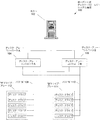
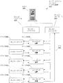
図1は、シングル・ポートによるデータ・ストーレジ・システムの構成を示す。システム100は、ホスト102、ディスク・アレー・コントローラ“A”104、ディスク・アレー・コントローラ“B”106、バス“A”108、バス“B”110、“A”ドライブ・アレー112、及び“B”ドライブ・アレー114を備えている。ドライブ・アレーは、互いに5ドライブを有するものとして説明される。“A”ドライブ・アレー112及び“B”ドライブ・アレー114は、単一ポートであり、バス“A”108又はバス“B”110に対して単一のインターフェースを提供する。ディスク・アレー・コントローラ“A”104及びディスク・アレー・コントローラ“B”106は、1以上のバスによりホスト102に接続され、かつデュアル・ポート式であり、これらは2つのディスク・ドライブ・バス・インターフェースをそれぞれ提供する。各ドライブ・アレー・コントローラのインターフェースは、コントローラのうちの一方が故障したときに、いずれかのコントローラがバス“A”108及びバス“B”110の両者上の通信をサポートできるように、構築される。各アレーにおけるディスク・ドライブ数、及びアレーにおけるドライブのデータ転送速度に従って、システムは、複数のコントローラのうちの一コントローラが故障した後、遅いデータ速度で動作してもよい。バス“A”108又はバス“B”110のいずれかの故障、関連するコネクタ、又は接続されているコンポーネントによるバス信号の不良は、バスに取り付けられた配列に記憶されたデータに対するアクセスを完全に禁止する。このようなバス“A”108、バス“B”110、及びバスを損なう恐れがある関連のコネクタ及び取り付けコンポーネントは、故障の単独点を表す。記憶データの再生には、バスを修理すること、又はディスク・ドライブを取り外し、取り付け具に機能しているバスをインストールすることが必要である。データの入手可能性の観点から、図1のアーキテクチャーは、コントローラの故障、又はバスに影響しないディスク故障の場合に入手可能性が低下し、かつバス故障、又はバスに影響するディスク又はコントローラの故障の場合にデータの入手可能性を失う恐れがある。
FIG. 1 shows the configuration of a single-port data storage system. The
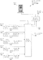
図2は、デュアル・ポート・データ・ストーレジ・システムのアーキテクチャーを示す。システム200は、ホスト202、ディスク・アレー・コントローラ“A”204、ディスク・アレー・コントローラ“B”206、バス“A”208、バス“B”210、及び“B”ドライブ・アレー212を備えている。“B”ドライブ・アレー212におけるディスクは、デュアル・ポート式であり、それぞれバス“A”208及びバス“B”210に単一インターフェースを提供するデュアル・ポートを提供する。ディスク・アレー・コントローラ“A”204及びディスク・アレー・コントローラ“B”206は、少なくとも1バスにより、かつ好ましい実施例においては、少なくとも2つのバスにより、ホスト202に接続されている。ディスク・アレー・コントローラ“A”204及びディスク・アレー・コントローラ“B”206は、デュアル・ポート式であり、それぞれ2つのディスク・ドライブ・バス・インターフェースを提供する。各ドライブ・アレー・コントローラのインターフェースは、バス“A”208及びバス“B”210の両者における通信をサポートできるように構築されており、コントローラのうちのいずれか一方が故障したときに、連続動作を提供する。“B”ドライブ・アレー212のデュアル・ポートの特性は、アレーにおける使用可能性がいずれかのドライブ・アレー・コントローラと通信可能にすることである。バス又はコントローラが故障した場合でも、システムはデータ・アクセスを提供し続ける。アクセスは転送速度及びアレーにおけるドライブ数に従って速度が低下する恐れがある。図2に示すアーキテクチャーは、図1のシステムと比較すると、バスの故障後に継続したデータ使用可能性を維持する利点があるが、しかしデュアル・ポート・ディスク・ドライブを使用することによるコストの増加がある。図1及び図2のアーキテクチャーは、例えば、SCSI、直列SCSI、直列ATA、又は光ファイバ・チャネルのような並列又は直列バス・インターフェースを使用してシステムを表すことができる。
FIG. 2 shows the architecture of a dual port data storage system. The system 200 includes a
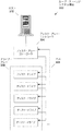
図3は、ループ・ストーレジ・システムの構成を示す。システム300は、ホスト302、ドライブ・アレー・コントローラ304、バス306、及びドライブ・アレー308を備えている。ドライブ・アレー・コントローラ304は、1以上のバスによりホスト302に接続されている。バス306は、ドライブ・アレー・コントローラ304、及びループにおけるドライブ・アレー308の各ドライブを直列に相互接続している。ドライブ・アレー・コントローラ304及びドライブ・アレー308は、バス306のループを形成するように入力ポート及び出力ポートを接続している。図3のシステムは、ディスク故障が発生したときに動作を継続することができ、バスの動作に影響しない。バス、コントローラの故障、又はバスの動作を中断させるディスク故障は、データの使用可能性の損失に帰結し、データをアクセスするためにバス、コントローラ又はディスク・ドライブの修理、又は他の取り付け具にドライブのインストールを必要とする。
FIG. 3 shows the configuration of the loop storage system. The
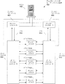
図4は、交換式のシングル・ポートによるディスク・ドライブを採用したストーレジ・システムの構成を示す。システム400は、ホスト402、ディスク・コントローラ“A”404、ディスク・コントローラ“B”406、スイッチ・コントロール408、バス“A”410、バス“B”412、ディスク・ドライブ414〜422及びスイッチング装置424〜432を備えている。ディスク・コントローラ“A”404及びディスク・コントローラ“B”406は、1以上のバスによりホスト402に接続されており、かつそれぞれ2ディスク・ドライブ・バスを提供するデュアル・ポート式である。バス“A”410及びバス“B”412は、ディスク・コントローラ“A”404及びディスク・コントローラ“B”406の両者に接続されている。他の実施例(図示なし)において、第1のディスク・コントローラがバス“A”410を備え、かつ第2のディスク・コントローラがバス“B”412を備えた2つのシングル・ポート・ディスク・コントローラを使用してもよい。スイッチング装置424〜432は、スイッチ・コントロール408により制御され、かつバス“A”410又はバス“B”412にディスク・ドライブ414〜422を従属接続している。スイッチング装置424〜432は、クロス・ポイント・スイッチを含むが、限定されることなく、任意形式のスイッチング装置、ポート・マルチプレクサ等であってもよい。スイッチ・コントロールは、スイッチング装置424〜432をホスト402に接続する1以上のバスを設けてもよく、かつI2Cバス、RSC232、又は他の直列又は並列バスを設けてもよい。代わって、スイッチング装置は、ディスク・コントローラ“A”404、ディスク・コントローラ“B”406、又は両者により制御されてもよい。他の実施例おいて、スイッチ・コントロールは、バス“A”410及びバス“B”412またはそのいずれかを採用してもよい。従って、スイッチング装置は、ホスト402により、バス“A”410又はバス“B”412を介してホスト402により直接制御されてもよく、バス“A”410又はバス“B”412により制御されてもよい。図4のアーキテクチャーは、多数のディスク及び図示よりもスイッチング装置を採用してもよい。図4の構成は、図示よりも多数のディスク及びスイッチング装置を採用してもよい。
FIG. 4 shows the configuration of a storage system that employs a replaceable single-port disk drive. The system 400 includes a host 402, a disk controller “A” 404, a disk controller “B” 406, a
スイッチング装置は、各ドライブがバス“A”410又はバス“B”412のいずれかを採用するように、各ドライブに対して個別的に構築され得る。これによって、バス故障の場合に通信を維持可能にし、かつバス間で負荷を平衡可能にする。図4の構成は、バス、ディスク又はコントローラ故障の場合に連続した動作を提供する。更に、スイッチング装置424〜432は、両者のバスからディスク・ドライブを切り離し可能にする。ディスク故障、又はバスの動作を不良にするディスク故障の場合に、関連したスイッチング装置は、ドライブを両者のバスから切り離すように構築されてもよい。図4に示すスイッチング方法は、各ドライブの各ポートを選択的にバス“A”410、バス“B”412に接続できる、又は両者のバスから切り離せるデュアル・ポート式ドライブに適用されてもよい。代わって、第3のバスは、バス故障の場合に更に高い転送速度を提供するように採用されてもよい。
The switching device can be constructed individually for each drive such that each drive employs either bus “A” 410 or bus “B” 412. This makes it possible to maintain communication in the event of a bus failure and to balance the load between the buses. The configuration of FIG. 4 provides continuous operation in the event of a bus, disk or controller failure. Furthermore, the switching
図5は、交換式のシングル・ポートによるディスク・ドライブを採用したストーレジ・システムの構成を示す。システム500は、ホスト502、ディスク・コントローラ“A”504、ディスク・コントローラ“B”506、ディスク・コントローラ“C”508、スイッチ・コントロール510、バス“A”520、バス“B”522、バス“C”524、及びドライブ/スイッチング・ユニット512から始まり、ドライブ/スイッチング・ユニット526で終わる複数のドライブ/スイッチング・ユニットを備えている。これらの実施例は、特定数のドライブ/スイッチング・ユニットに限定されない。ドライブ/スイッチング・ユニット512は、デュアル・ポート式ドライブ514、デュアル・ポート式ドライブ514の第1ポートに接続された第1のスイッチング装置516、及びデュアル・ポート式ドライブ514の第2ポートに接続された第2のスイッチング装置518を備えている。ストーレジ装置516は、ドライブ514の第1ポートをバス“A520”、バス“B”522又はバス“C”524に接続可能にする。同様に、スイッチング装置518は、ドライブ514の第1ポートをバス“A”520、バス“B”522又はバス“C”524に接続可能にしている。これらのスイッチング装置は、制御ロジック、例えば12Cのようなバス・インターフェース、又はホスト502を各スイッチング装置の機能を制御可能にする他の回路のであってもよいスイッチ・コントロール510を介して制御される。代わって、スイッチ・コントロール510は、1以上のディスク・コントローラ、又は1以上のバスに接続されてもよい。ディスク・コントローラ“A”504、ディスク・コントローラ“B”506及びディスク・コントローラ“C”508は、1以上のバスによりホスト502に接続され、かつそれぞれ2つのディスク・ドライブ・バスを提供するデュアル・ポート式である。バス“A”520〜524は、バスを動作不良にする1ディスク・コントローラの故障の場合に、全てのバスが可動状態に留まるようにして、ディスク・コントローラ“A”504〜508のうちの異なるディスク・コントローラの2つのポートにそれぞれ接続される。図5の構成の他の実施例おいて、各ディスク・ドライブの第1ポートに接続されたスイッチング装置は、第1のスイッチ・コントロールにより制御され、かつ各ドライブの第2ポートに接続されたスイッチング装置は、第2のスイッチ・コントロールに接続される。第1及び第2のスイッチ・コントロールは、ホストにより直接制御可能とされ、スイッチ・コントロールに接続された1以上のディスク・コントローラを介してホストにより制御可能とされ、又は1以上のディスク・コントローラにより接続可能とされる。スイッチング装置は、複数のバスのうちの一バスに対して複数のドライブ・ポート接続するように採用されてもよく、又は全てのバスからポートを分離するために採用されてもよい。スイッチング装置は、スイッチング、マルチプレクサ、ポート・コントローラ、クロス・ポイント・スイッチ、構造物等を含む前述の機能を提供するように構築可能な任意の装置を備えてもよい。
FIG. 5 shows the configuration of a storage system that employs a replaceable single-port disk drive. The
図5の構成は、1以上のディスク・コントローラの故障後に、システム動作を継続可能にする。加えて、図5の構成は、パフォーマンスを最適化するためにデータ負荷を複数のディスク・コントローラ間に分散可能にする。ディスク・ドライブ数と、ディスク・ドライブ、バス及びディスク・コントローラのデータ速度とに従って、図5の構成は、ディスク・ドライブ、バス又はディスク・コントローラの故障後の近最適パフォーマンス(near optimum performance)を提供することができる。従って、以上の構成は、ディスク・コントローラのバスの故障後に継続して高いパフォーマンスが望ましいシステムに採用されてもよい。 The configuration of FIG. 5 allows system operation to continue after failure of one or more disk controllers. In addition, the configuration of FIG. 5 allows the data load to be distributed among multiple disk controllers to optimize performance. Depending on the number of disk drives and the data rate of the disk drive, bus, and disk controller, the configuration of FIG. 5 provides near optimum performance after failure of the disk drive, bus, or disk controller. can do. Therefore, the above configuration may be adopted in a system in which high performance is desired continuously after a failure of the disk controller bus.
図6は、ループ・バイパス・ストーレジ・システムの構成を示す。システム600は、ホスト602、ディスク・コントローラ604、スイッチ・コントロール606、ドライブ608〜616、スイッチング装置618〜626及びバス630を備えている。ディスク・コントローラ604は、1以上のバスによりホスト602に接続されている。バス630は、それぞれ関連するドライブをバス630に直列接続するか、又はドライブをバイパスするスイッチング装置618〜626の各スイッチング装置に、ディスク・コントローラ604を直列接続する。全てのスイッチング装置がイネーブルされると、全てのドライブが直列接続される。これらのスイッチング装置は、スイッチ・コントロール606を介してホスト602により、又はディスク・コントローラ604により制御され得る。図6に示す構成は、ディスク故障、又はバス動作に影響するディスク故障の場合に、故障したドライブがバイパスされ得る、又はシステムが動作し続けられるように、ディスク接続を個別的にバイパス可能にする。スイッチング装置618〜626は、複数のディスクを直列接続又はバイパスできる任意形式のものでよい。スイッチング装置618〜626及びスイッチ・コントロール606は、単一ユニットとして実施されてもよい。スイッチング装置618〜626及びスイッチ・コントロール606は、ポート・バイパス・コントローラを備えてもよい。
FIG. 6 shows the configuration of the loop bypass storage system. The
ループ・バイパス方法は、1以上のドライブを切り離すために採用されてもよい。1以上のドライブは、ポート・バイパス・コントローラの各ポートに接続されてもよい。図7は、各バイパス・コントローラ・ポートに接続された2つのドライブを有するループ・バイパス・ストーレジ・システムを示す。システム700は、ホスト702、ディスク・コントローラ704、ディスク・ドライブ706〜724、・バイパス・コントローラ726及びバス728を備えている。これらのドライブは、ドライブ706、708がポート・バイパス・コントローラ726の第1ポートに接続され、ドライブ710、712が第2ポートに接続され、ドライブ714、716が第2ポートに接続され、ドライブ718、720が更に他のポートに接続され、かつドライブ722、724が更に他のポートに接続されるように、複数対に配列される。バス728は、ディスク・コントローラ704をポート・バイパス・コントローラ726に接続する。他の実施例おいて、2つのバスは、バス故障の場合に、冗長性を提供するように、ディスク・コントローラ及びポート・バイパス・コントローラを接続してもよい。任意又はポート・バイパス・コントローラ726のポートは、ドライブ故障、又はバスを不良にするドライブ故障の場合に切り離せるように、信号が接続された2つのドライブを介してポートに転送可能に、又はポートをバイパス可能にさせるように構築されてもよい。図7はポート・バイパス・コントローラ726の各ポートに接続された2つのドライブを示しているが、本発明の範囲内で2つ以上のドライブが接続されてもよい。図7はポート・バイパス・コントローラを採用しているが、説明した機能を発生する任意の装置及び構成を採用してもよい。
A loop bypass method may be employed to disconnect one or more drives. One or more drives may be connected to each port of the port bypass controller. FIG. 7 shows a loop bypass storage system having two drives connected to each bypass controller port. The system 700 includes a host 702, a disk controller 704,
ループ・バイパス構成は、各ドライブがデュアル・ポート式である場合に、各ポートに接続される複数のドライブを採用することができる。図8は、各ポートに接続された2つのデュアル・ポート式ドライブを有するループ・バイパス・システムを示す。システム800は、ホスト802、ディスク・コントローラ804、ディスク・コントローラ806、ポート・バイパス・コントローラ808、バス810、ポート・バイパス・コントローラ812、バス814及びディスク・ドライブ816〜824を備えている。ディスク・コントローラ804及びディスク・コントローラ806は、1以上のバスを介してホスト802にそれぞれ接続されている。ディスク・コントローラ804は、バス810を介してポート・バイパス・コントローラ808に接続されている。ディスク・コントローラ806は、バスbを介してポート・バイパス・コントローラ812に接続されている。他の実施例おいて、1以上のバスは、ディスク・コントローラ804をポート・バイパス・コントローラ808に接続してもよく、かつ1以上のバスは、ディスク・コントローラ806をポート・バイパス・コントローラ812に接続してもよい。他の実施例おいて、各ディスク・コントローラは、両ポート・バイパス・コントローラを接続してもよい。ディスク・ドライブ816〜824は、デュアル・ポート式であり、かつ各ドライブがポート・バイパス・コントローラ808に接続された第1ポートを有し、かつポート・バイパス・コントローラ812に接続された第2ポートを有する。従って、各ディスク・ドライブは、第1ポートにおけるバス810、又はドライブの第2ポート上のバス814、又は両方のバスにより形成されたループに接続するように個別的に構築されてもよい。ディスク故障、又はバス信号を損なうディスク故障の場合には、ポート・バイパス・コントローラ808、又はポート・バイパス・コントローラ812の構成、又は両ポート・バイパス・コントローラの構成によってドライブを切り離してもよい。ディスク・コントローラ、バス故障、コネクタ故障、又はポート・バイパス・コントローラの故障の場合には、機能しているディスク・コントローラ、バス又はポート・バイパス・コントローラを使用してドライバからデータをアクセスしてもよい。
The loop bypass configuration can employ a plurality of drives connected to each port when each drive is a dual port type. FIG. 8 shows a loop bypass system having two dual-ported drives connected to each port. The
2つ以上のデュアル・ポート式であるディスク・ドライブは、ポート・バイパス・コントローラの各ポートに接続されもよい。図9は、ポート・バイパス・コントローラに接続された2つのデュアル・ポート装置を有するループ・バイパス・ストーレジ・システムを示す。システム900は、ホスト902、ディスク・コントローラ904、バス906、ポート・バイパス・コントローラ908、ディスク・ドライブ910〜928、ディスク・コントローラ930、バス932、及びポート・バイパス・コントローラ934を備えている。ディスク・コントローラ904及びディスク・コントローラ930は、1以上のバスによりホスト902に接続されている。ディスク・コントローラ904は、バス906を介してポート・バイパス・コントローラ934に接続されている。ディスク・コントローラ930は、バス932を介してポート・バイパス・コントローラ934に接続されている。ディスク・ドライブ910〜928は、デュアル・ポート式であり、かつ各ドライバは、ポート・バイパス・コントローラ908に接続された第1ポート、及びポート・バイパス・コントローラ934に接続された第2ポートを有する。他の実施例おいて、ディスク・コントローラ904は、更にポート・バイパス・コントローラ934に接続されており、かつディスク・コントローラ930もポート・バイパス・コントローラ908に接続されている。ポート・バイパス・コントローラ908及び934は、ディスク・ドライブ・ポートに対する接続を確立するように、又はディスク・ドライブに対する接続をバイパスするように個別的に構築可能であり、ディスク故障又はポート接続を損なう故障の場合に各ドライブを切り離せるようにしている。ディスク・ドライブはデュアル・ポート式であり、かつ2つのポート・バイパス・コントローラを採用しているので、ディスク・コントローラ故障の場合に、図9のシステムは連続した動作が得られる。
Two or more dual-port disk drives may be connected to each port of the port bypass controller. FIG. 9 shows a loop bypass storage system having two dual port devices connected to a port bypass controller. The system 900 includes a
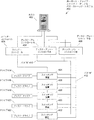
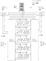
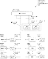
図10は、多数パスの冗長ストーレジ・システムを示す。システム1000は、ホスト1002、ホスト・バス“A”1004、ホスト・バス“B”1006、ディスク・コントローラ“A”1008、ディスク・コントローラ”B”1010、構造物・バス“A”1012、構造物・バス“B”1014、構造物“A”1016、構造物“B”1018、及びディスク・ドライブ1020〜1028を備えている。ディスク・コントローラ“A”1008、及びディスク・コントローラ“B”1010は、ホスト・バス“A”1004及びホスト・バス“B”1006によりホスト1002に共に接続されている。ディスク・ドライブ1020〜1028は、構造物“A”1016に接続された第1ポート及び構造物“B”1018に接続された第2ポートによりそれぞれデュアル・ポート式である。構造物“A”1016及び構造物“B”1018は、ファイバ・チャネル構造物、スイッチ、マルチプレクサ、クロス・ポイント・スイッチ等を含む任意かつ全てのスイッチ形式及びスイッチング方法を含むものであってもよい。構造物はアドレス・マップド制御(address mapped control)を有してもよく、かつディスク・コントローラ“A”1008又はディスク・コントローラ“B”1010を介してホスト1002により制御されてもよい。代わって、個別的なバス、又は例えばI2Cのような複数のバス(図示なし)は、ホスト1002から構造物“A”1016及び構造物“B”1018へ制御及び構成情報を転送させてもよい。更に、構造物“A”1016及び構造物“B”1018は、ディスク・コントローラ“A”1008及びディスク・コントローラ“B”1010またはそのいずれかにより全体的にも部分的に制御及び構築されてもよい。構成及び制御タスクは、ホスト1002とディスク・コントローラ“A”1008及びディスク・コントローラ“B”1010またはそのいずれかとの間で共有されてもよい。
FIG. 10 illustrates a multiple path redundant storage system. The
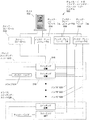
図11は、他の多数パスの冗長ストーレジ・システムを示す。システム1000は、システム・インターフェース1102、システム・バス“A”1104、システム・バス“B”1106、インターフェース・コントローラ“A”1108、インターフェース・コントローラ“B”1110、インターフェース・バス“A”1112、インターフェース・バス“B”1114、ディスク・コントローラ“A”1116、ディスク・コントローラ“B”1118、構造物バス“A”1120、構造物バス“B”1122、構造物“A”1124、構造物“B”1126、構造物制御バス“A”1128、構造物制御バス“B”1130、及びドライブ・グループ1132〜1140を備えている。インターフェース・コントローラ“A”1108及びインターフェース・コントローラ“B”1110は、システム・バス“A”1104及びシステム・バス“B”1106に接続する。2つのシステム・バスは、冗長な通信パスを含み、複数のシステム・バスのうちの一システム・バスが故障した場合に、両インターフェース・コントローラと連続した通信を可能にする。インターフェース・コントローラ“A”1108及びインターフェース・コントローラ“B”1110は、インターフェース・バス“A”1112及びインターフェース・バス“B”1114を介してディスク・コントローラ“A”1116及びディスク・コントローラ“B”1118に接続されており、複数のインターフェース・バスのうちの一インターフェース・バスが故障した場合に、いずれかのインターフェース・コントローラと、いずれかのディスク・コントローラとの間で連続した通信を可能にさせる。ディスク・コントローラ“A”1116及びディスク・コントローラ“B”1118は、構造物バス“A”1120及び“A”ドライブ・アレー1122を介して構造物“A”1124及び構造物“B”1126に接続され、複数の構造物バスのうちの一構造物バスが故障した場合に、いずれかの構造物コントローラと、いずれかの構造物との間で連続した通信を提供する。構造物制御バス“A”1128及び構造物制御バス“B”1130は、インターフェース・コントローラ“A”1108からインターフェース・コントローラ“B”1110から“A”ドライブ・アレー1124及び構造物“B”1126へ冗長な制御パスを設け、かついずれかの構造物制御バスが故障した場合に、いずれかのインターフェース・コントローラによりいずれかの構造物の構築を可能にする。構造物“A”1124は、個別的な接続によりドライブ・グループ1132〜1140の各ドライブ・グループに接続される。ドライブ・グループにおけるドライブは、デュアル・ポート式である。構造物“B”1126は個別的な接続によりドライブ・グループ1132〜1140における各グループに接続されている。構造物“A”1124は、デュアル・ポート式ドライブ、又は各ドライブ・グループを備えた複数のドライブのうちの第1ポートに接続され、かつ“B”ドライブ・アレー1126は、デュアル・ポート式ドライブ、又は各ドライブ・グループを備えた複数のドライブのうちの第2ポートに接続される。システム・バス、インターフェース・バス、構造物バス、構造物制御バス、及びドライブ・グループ接続の双対性は、システムにおけるあらゆるデータ・パスに対して独立性又は冗長パスを提供する。バスの双対性に関連したインターフェース・コントローラ、ディスク・コントローラ、及び構造物の双対性は、インターフェース・コントローラが故障した場合に、連続した動作が得られる。従って、図11に示したシステムは、バス、コントローラ又は構造物に関して単一点の故障は存在しない。
FIG. 11 shows another multi-path redundant storage system. The
バス、コネクタ、ディスク・ドライブ、構造物及びコントローラに加えて、隔離及び冗長方法は、システムがシステムの動作不能になりかねない単一点の故障が存在しないように、ストーレジ・システムにおける電力分配に適用されてもよい。図12は、冗長な多数パスのストーレジ・システムの電力分配を示す。電力は、コネクタ1202を介して供給される。代わって、1以上のコネクタを採用してもよい。コネクタ内でコンタクト・ピン以上が同様電圧を提供してもよく、1本のピンが接続に失敗した、又は所望の以上の抵抗より高い場合に、パスの双対性が得られる。電力バス“A”1204は、ローカル・レギュレータ1208に電力を供給し、ローカル・レギュレータ1212は、オプションとしてローカル・レギュレータ1216により示すように、1以上の付加的なローカル・レギュレータに対して電力を供給してもよい。ローカル・レギュレータ1208は構造物“A”1206に電力を供給する。ローカル・レギュレータ1212は構造物“B”1210に電力を供給する。オプションのローカル・レギュレータ1216は、ディスク・コントローラ1214に電力を供給してもよい。他のローカル・レギュレータ(図示なし)は、付加的なディスク・コントローラ、及びインターフェース・コントローラ、離散的な回路、又は例えば環境モニタのような他の回路に電力を供給してもよい。ローカル・レギュレータは、ディスク・ドライブと比較して比較的に低電力を消費する集積回路のようなコンポーネントに、所望の電圧に調節された電力を供給するように採用されてもよい。冗長なインターフェース・コントローラを有するシステム、ディスク・コントローラ及び構造物は、データをアクセスするために冗長なコンポーネントを採用することができるので、各コンポーネント用にローカル・レギュレータを採用することもでき、単独のレギュレータ故障の場合に連続したシステム動作が得られる。更に、図12のコネクタ1202は、電力バス“B”1218に接続された1本以上のピンを有する。電力バス“B”1218は、電圧レギュレータ1220及び1222に電力を供給する。レギュレータ1220及び1222は、いずれかのレギュレータにより電力を供給できるように接続され、かつダイオード又は他のコンポーネントのような切り離し回路を含むものでもよい。代わって、レギュレータ1220及び1222は、各レギュレータをイネーブル又はディスエーブル状態にすることが可能な入力信号を含むものでもよい。レギュレータは、書き込み可能レジスタ、I2Cバス、又は他の信号線により制御されてもよい。電圧レギュレータ1220及び1222は、調節電力を制御1224、制御1228及びオプションとして制御1232により表す1以上の付加的な制御に供給される。制御1224はディスク・グループ1226に対する電力を制御する。制御1228はディスク・グループ1230に対する電力を制御する。制御1232はディスク・グループ1234に対する電力を制御する。付加的な制御ユニット(図示なし)は、付加的なディスク・グループ、又は環境モニタ、ファンのような他のコンポーネントに対する電力制御してもよい。制御1224、1228、1232及び他の制御は、スイッチ、ヒューズ、ブレーカ、トランジスタ(電界効果トランジスタ、SCR(シリコン制御トランジスタ)又はディスク・グループ若しくは他のコンポーネントに対して選択的に電力を供給するように採用された任意の他の装置を含む)を備えてもよい。制御は、電流及び電圧またはそのいずれの検知を含むものでよく、かつ自動的な方法又は制御信号に応答して動作してもよい。図12は、電力冗長及び切り離し方法が、レギュレータの故障後に利用可能な状態を維持するように、及び故障したドライブを含むグループにおける1以上のディスク・ドライブに対する電力を遮断してシステムにおける電力を浪費しない又は過度の電力を流すコンポーネントを切り離すように、データ・ストーレジ・システムのコンポーネントに適用可能であること示す。前述のように、故障したドライブ又はディスク・グループからのデータは、予備容量を使用してコピー又は再構築され、かつセーブ可能とされる。従って、本発明の実施例は、データの損失に帰結する単独ポイントの故障がないデータ・ストーレジ・システムを提供することができる。挿入用語構造物は、データ・ストーレジ装置とディスク・コントローラとの間の構築可能な接続を提供することができる任意形式を示し、かつファイバ・チャネル構造物、スイッチ、クロス・ポイント・スイッチ、マルチプレクサ、ポート・バイパス・コントローラ及び他の装置を含まなければならない。構造物は、図に示されたスイッチ、スイッチング装置、又はポート・バイパス・コントローラを置換してもよい。
In addition to buses, connectors, disk drives, structures and controllers, isolation and redundancy methods apply to power distribution in storage systems so that there is no single point of failure that can cause the system to become inoperable May be. FIG. 12 illustrates the power distribution of a redundant multi-path storage system. Electric power is supplied through the connector 1202. Instead, one or more connectors may be employed. More than the contact pin in the connector may provide the same voltage, and path duality is obtained when one pin fails to connect or is higher than the desired resistance. Power bus “A” 1204 supplies power to
以上の図は、スイッチ、スイッチング装置、ポート・バイパス・スイッチ及び構造物を含み、データ・ストレージ装置とディスク・コントローラとの間で構築可能な接続を提供した。 The above diagram includes switches, switching devices, port bypass switches and structures, and provided a connectable connection between the data storage device and the disk controller.
本発明の実施例は、複数のスイッチング装置を備え、かつ単一ユニットとしてキャビネット又は他の取り付け具から挿入又は取り外される多数のディスク・アッセンブリ(MDA)に都合良く採用可能とされる。MDAは、スイッチング装置を含むことができ、スイッチング装置及び構造物を含むことができ、スイッチング装置、構造物及びディスク・コントローラを含むことができ、又はデータ・ストーレジ装置、構造物及びディスク・コントローラを含むことができ、又はデータ・ストーレジ装置、構造物、ディスク・コントローラ及びインターフェース・コントローラを含むことができる。換言すれば、図により例示された本発明の実施例は、MDAに配置されたコンポーネントと、キャビネット、棚又は他の取り付け具に配置されるコンポーネントとの間で分割されてもよい。このような分割は、MDAのサイズ、コネクタ数、インターフェース形式、バス信号の駆動力及び他の要素を反映させることができる。いくつかの実施例において、MDAは、横方向に搭載されたストーレジ・システムを採用してもよく、そのデバイスは、少なくとも1ストーレジ装置本体の最長軸がMDAをキャビネット、棚又は他の取り付け具に挿入する方向に対して直交して搭載される。これらの実施例は、例えばディスク・ドライブのようなストーレジ装置のコネクタがバックプレーン上に配置されたコネクタと直接係合できるようにして、中間のコネクタ、ケーブル等、及び中間接続によりもたらされる故障の可能性がある追加ポイントをなくす。 Embodiments of the present invention can be advantageously employed in multiple disk assemblies (MDAs) that include multiple switching devices and are inserted or removed from a cabinet or other fixture as a single unit. An MDA can include switching devices, can include switching devices and structures, can include switching devices, structures and disk controllers, or can include data storage devices, structures and disk controllers. Or can include data storage devices, structures, disk controllers and interface controllers. In other words, the embodiment of the invention illustrated by the figure may be divided between components located on the MDA and components located on a cabinet, shelf or other fixture. Such a division can reflect the size of the MDA, the number of connectors, the interface type, the driving power of the bus signals, and other factors. In some embodiments, the MDA may employ a laterally mounted storage system, the device having at least one storage device body with the longest axis of the MDA in the cabinet, shelf or other fixture. It is mounted orthogonal to the direction of insertion. These embodiments allow a storage device connector, such as a disk drive, to engage directly with a connector located on the backplane to prevent failure caused by intermediate connectors, cables, etc., and intermediate connections. Eliminate possible additional points.
ホスト・システム及び1以上のインターフェース・コントローラ、またはそのいずれか、さらに1以上のディスク・コントローラにおいて動作するコンピュータ・プログラム・コードは、本発明の構造物を構築するために採用されてもよい。構造物は、1以上のホスト・コンピュータにおいて動作するコンピュータ・プログラム・コードにより制御されてもよい。このようなプログラム・コードは、パフォーマンス監視及び負荷平衡機能を含むものでもよい。構造物の構築は、例えばトランザクション処理又はビデオ・ストリームのように提供されたサービスを反映させるように、検出された故障の結果として、又は負荷、データ形式、データ・サイズ、データ・ストーレジ・フォーマット、所望の応答時間等を含む他の条件に応答して実行されてもよい。1以上のディスク・コントローラは、複数の構造物を制御してもよい。ディスク・コントローラにおいて動作するコンピュータ・プログラム・コードは、故障又は他の条件に応答して構造物を構築してもよい。複数の構造物の構築は、1以上のホスト・コンピュータと1以上のディスク・コントローラとの間で共有される。前述のように、スイッチ・コントロールは、I2Cのような1以上の制御バスを採用してもよく、1以上のディスク・バス又は両者を採用してもよい。構造物は、1以上のディスク・アレー・バス上の装置としてマッピングされてもよく、かつ1以上の構造物用の制御信号は、ディスク・アレー又はバスを介して搬送されてもよい。いくつかの図は、個別的なスイッチ・コントロール・ブロックを示す。いくつかの実施例おいて、スイッチ・コントロール・ブロックは、一対の構造物であってもよい。 Computer program code running on the host system and / or one or more interface controllers and / or one or more disk controllers may be employed to construct the structure of the present invention. The structure may be controlled by computer program code running on one or more host computers. Such program code may include performance monitoring and load balancing functions. The construction of the structure may be the result of a detected failure or to reflect the service provided, eg transaction processing or video stream, or load, data format, data size, data storage format, It may be executed in response to other conditions including a desired response time or the like. One or more disk controllers may control a plurality of structures. Computer program code running on the disk controller may construct the structure in response to a failure or other condition. The construction of multiple structures is shared between one or more host computers and one or more disk controllers. As described above, the switch control may employ one or more control buses such as I2C, one or more disk buses, or both. The structure may be mapped as a device on one or more disk array buses, and control signals for the one or more structures may be conveyed via the disk array or bus. Some figures show individual switch control blocks. In some embodiments, the switch control block may be a pair of structures.
図13はホスト及びディスク・コントローラまたはそのいずれかにおいて動作するシステム構成コンピュータ・プログラム・コードにより実行されるステップを示す。図13の処理は、図10及び図11に示すようなシステムに適用可能とされる。処理1300はステップ1300から開始され、チェックを実行してエラー条件が存在するか否かを判断する。エラー条件は、例えばディスク・ドライブ、ディスク・コントローラ又はホスト・システムにより検出された読み出し又は書き込みエラーのようなエラーを含むものでもよい。ディスク・ドライブによりエラーが検出されたときは、エラーをディスク・コントローラに報告してもよく、かつディスク・コントローラによりチェックされてもよく、及びホスト・システムまたはそのいずれかに転送されてもよい。ディスク・コントローラがエラーを検出したときは、エラーをチェックしてもよく、かつホスト・システムまたはそのいずれかに転送されてもよい。代わって、エラーは、ホスト・システムによって検出されてもよい。ステップ1304において、テストを実行してホストがシステム・バス“A”を使用してインターフェース・コントローラ“A”と通信できるか否かを判断してもよい。ステップ1306において、テストを実行してホストがシステム・バス“B”を使用してインターフェース・コントローラ“A”と通信できるか否かを判断してもよい。ステップ1308において、テストを実行してホストがシステム・バス“A”を使用してインターフェース・コントローラ“B”と通信できるか否かを判断してもよい。ステップ1310において、テストを実行してホストがシステム・バス“A”を使用してインターフェース・コントローラ“B”と通信できるか否かを判断してもよい。ステップ1304〜1310は、システム・バス“A”及びシステム・バス“B”を使用してインターフェース・コントローラ“A”及びインターフェース・コントローラ“B”と通信できるか否かを判断する。ステップ1312において、ステップ1304〜1310により検出されたエラーをホスト又は他のシステムに報告する。ステップ1314において、例えば報告されたエラーを再点検するようなチェックを実行してホスト又は他のシステムが少なくとも1インターフェース・コントローラと通信することができるか否かを判断する。ホスト又は他のシステムが少なくとも1インターフェース・コントローラと通信できないのであれば、ステップ1316において処理を終了する。ホスト又は他のシステムは少なくとも1インターフェース・コントローラと通信することができるとステップ1314において実行したチェックが判断したときは、処理をステップ1318に継続させ、テストを実行し、ディスク・コントローラ“A”を使用してディスク・コントローラ“A”をアクセスできるか否かを判断する。ステップ1320において、テストを実行し、インターフェース・バス“B”を使用してディスク・コントローラ“A”をアクセスできるか否かを判断する。ステップ1322において、テストを実行し、インターフェース・バス“A”を使用してディスク・コントローラ“B”をアクセスできるか否かを判断する。ステップ1324において、テストを実行し、インターフェース・バス“B”を使用してディスク・コントローラ“B”をアクセスできるか否かを判断する。ステップ1326において、ステップ1318〜1324により検出されたエラーを報告する。ステップ1328において、テスト結果をチェックして少なくとも1ディスク・コントローラをアクセスできるか否かを判断する。どのディスク・コントローラもアクセスできないときは、ステップ1330において処理を終了する。少なくとも1ディスク・コントローラをアクセスできるときは、処理がステップ1332に行き、テストを実行し、ディスク・コントローラ“A”を使用して構造物“A”をアクセスできるか否かを判断する。ステップ1334において、テストを実行し、構造物“B”を使用して構造物“A”をアクセスできるか否かを判断する。ステップ1336において、テストを実行し、構造物“A”を使用して構造物“B”をアクセスできるか否かを判断する。ステップ1338において、テストを実行し、構造物“B”を使用して構造物“B”をアクセスできるか否かを判断する。ステップ1340において、ステップ1332〜1338において検出されたエラーを報告する。ステップ1342において、テスト結果をチェックして少なくとも1構造物をアクセスできるか否かを判断する。どの構造物もアクセスできないときは、ステップ1344において処理を終了する。少なくとも1構造物をアクセスできるときは、処理をステップ1346に継続させる。ステップ1346において、テストを実行して構造物“A”は取り付けられている全てのドライブをアクセスできるか否かを判断する。このようなテストは、ドライブ・レジスタの読み出し及び書き込みまたはそのいずれか、さらに、ドライブ媒体のデータ読み出し及び書き込みまたはそのいずれかを含むものでもよい。全てのドライブがアクセス不能又は正しく動作しないときは、ステップ1348において1以上のドライブを切り離すように構造物“A”を構築し、次に処理をステップ1350に継続させる。ステップ1346において、テストを実行して全てのドライブがアクセス可能であり、かつ正しく動作すると判断したときは、処理をステップ1350に継続させる。ステップ1350において、テストを実行して構造物“B”が取り付けられた全てのドライブをアクセスできるか否かを判断する。いくつかのドライブをアクセスできない、又は正しく動作しないときは、ステップ1352において1以上のドライブを切り離すように構造物“B”を構築し、次に処理をステップ1354に継続させる。ステップ1354におい、アクセス不能又は故障したドライブからのデータを再構築又はコピーし、かつ他の装置に格納してもよく、又はフォールト・トレランスが得られるように、他のシステムに格納してもよい。入出力コマンドは、再マッピングされて、機能しているインターフェース・コントローラ、ディスク・コントローラ又は構造物を前のテストにより認識されたように利用してもよい。次に、ステップ1356において処理を終了する。ステップ1350においてテストを実行して全てのドライブがアクセス可能であり、かつ正しく動作すると判断したときは、処理をステップ1356に継続させる。ステップ1350において、テストを実行して全てのドライブがアクセス可能であり、かつ正しく動作すると判断したときは、ステップ1356において処理を終了する。更に、実行したテストの結果は、電力が故障したコンポーネントに供給されないように、例えば図12に示した電力回路を構築するために採用されてもよい。実行されるテスト、実行されるテストの順序、構造物の構成、データの再構築、及び入出力の再マッピングは、構造物又は複数の構造物のポートに取り付けられたディスク・ドライブの数を含め、ホスト・バスの数、インターフェース・コントローラ、ディスク・コントローラ、構造物の数及び形式、及びディスク・ドライブの数を含むストーレジ・システムの構成に従って変更されてもよい。報告されたエラーの形式は、テスト又はテスト・セットを選択するために使用されてもよい。代わって、報告されたエラーに続き、テストの範囲は、ストーレジ・サブシステムの総合条件を判断するように実行してもよい。種々のシステム・コンポーネントの動作が予め定めた順序により実行されるテストの階層的な順序が存在してもよい。図13において実行されたテストは、ホスト又は他のシステムにより実行されてもよく、又はストーレジ・サブシステム内のコンポーネントにより実行されてもよい。テストを実行するコンピュータ・プログラム・コードは、システムの個々のコンポーネントに存在してもよく、又は他のシステム又は他のコンポーネントから転送されてもよい。テストは、コンポーネントにおいてセルフ・テストのコンピュータ・プログラム・コードの実行を含むものでもよい。例えば、ディスク・ドライブは、パワー・オンのセルフ・テスト・ルーチンを含むものでもよく、かつこのようなルーチンは、ディスク・ドライブの動作をチェックするために図13において実行されたテストの一部として実行されてもよい。
FIG. 13 shows the steps performed by the system configuration computer program code running on the host and / or disk controller. The processing of FIG. 13 can be applied to a system as shown in FIG. 10 and FIG. Process 1300 begins at step 1300 where a check is performed to determine if an error condition exists. Error conditions may include errors such as read or write errors detected by a disk drive, disk controller or host system, for example. When an error is detected by the disk drive, the error may be reported to the disk controller and checked by the disk controller and forwarded to the host system or any of them. When the disk controller detects an error, the error may be checked and forwarded to the host system or either. Alternatively, the error may be detected by the host system. In
本発明の実施例は、ストーレジ・キャビネット、仕切り、棚等のように取り付け具にインストール及び取り外し可能なメンテナンス・フリーの多数のディスク・ストーレジ・アッセンブリを提供するように、採用されてもよい。多数のインターフェース・コントローラ、ディスク・コントローラ、バス及び構造物は、ディスク、ディスク・コントローラ、インターフェース・コントローラ、コネクタ又はバスの故障後の連続動作を可能とする。多数のドライブを有するシステムは、バス又はディスク・コントローラが故障した後、システム・パフォーマンスを高く維持できるように、 図5に示すように、第3のバスを採用してもよい。本発明の精神内でディスク・ドライブの数、ディスク・コントローラ、インターフェース・コントローラ、バス、スイッチング装置の形式及びその制御を含め、開示した実施例の種々の置換が可能である。 Embodiments of the present invention may be employed to provide a number of maintenance-free disk storage assemblies that can be installed and removed from fixtures such as storage cabinets, partitions, shelves, and the like. A number of interface controllers, disk controllers, buses and structures allow for continuous operation after a disk, disk controller, interface controller, connector or bus failure. A system with a large number of drives may employ a third bus, as shown in FIG. 5, to maintain high system performance after a bus or disk controller failure. Various substitutions of the disclosed embodiment are possible within the spirit of the present invention, including the number of disk drives, disk controllers, interface controllers, buses, switching device types and controls.
以上の説明は、本発明の実施例を説明するためにディスク・ドライブ及びディスク・コントローラを採用して種々の説明をしたものであった。本発明の実施例は、特定数のストーレジ装置に限定されず、かつストーレジ媒体の形式及びバスの形式を含むデータ・ストーレジ装置に限定されない。ディスク・コントローラは、ストーレジ装置からデータをアクセスするために採用された任意形式のコントローラに関連する必要がある。更に、ディスク・コントローラは、RAID、ECC又は他のフォーマットのようなフォールト・トレラント・データ・フォーマット機能を提供してもよい。データ・ストーレジ装置は、限定されることなく、ハード・ディスク、光ドライブ、固体メモリ・デバイス等を含むRAMドライブを含む電気的、磁気的、光学的又は化学的データ・ストーレジ装置を含む任意形式のデータ・ストーレジ装置を備えていてもよく、かつそれらの組み合わせを含むものでもよく、更に揮発性及び不揮発性データ・ストーレジ装置の組み合わせを含むものでもよい。1以上のディスク・コントローラと1以上のストーレジ装置とを相互接続する構造物又は複数の構造物は、複数のディスク・コントローラと複数のスイッチ・コントロールとの間で構築可能な接続を可能にする任意の装置又は複数装置であってもよく、かつインターフェース形式及びデータ・フォーマット変換を含むものでもよい。例えば、構造物は、直列取り付けSCSIストーレジ装置及びインターフェース信号をコントローラに通信されるファイバ・チャネル信号に変換してもよい。インターフェース・コントローラは、インターフェース形式及びデータ・フォーマット変換を提供してもよく、更に1以上の構造物を構築するようにコンピュータ・プログラム・コードを実行してもよい。 In the above description, various explanations have been made by adopting a disk drive and a disk controller in order to describe an embodiment of the present invention. Embodiments of the present invention are not limited to a specific number of storage devices and are not limited to data storage devices including storage media types and bus types. The disk controller needs to be associated with any type of controller employed to access data from the storage device. In addition, the disk controller may provide fault tolerant data formatting functions such as RAID, ECC or other formats. Data storage devices can be any type including electrical, magnetic, optical or chemical data storage devices including, but not limited to, RAM drives including hard disks, optical drives, solid state memory devices, etc. A data storage device may be provided and may include a combination thereof, and may further include a combination of volatile and non-volatile data storage devices. A structure or structures that interconnect one or more disk controllers and one or more storage devices is optional to allow a constructable connection between multiple disk controllers and multiple switch controls Or may include interface type and data format conversion. For example, the structure may convert serially attached SCSI storage device and interface signals into Fiber Channel signals that are communicated to the controller. The interface controller may provide interface type and data format conversion and may execute computer program code to build one or more structures.
本発明の以上の説明は、図示及び説明を目的として提供された。これは、余すことなく、又は本発明を開示したそのものフォームに制限されることを意図するものではなく、他の変更及び変形は以上の技術に照らして可能である。実施例は、本発明の原理及びその実際的なアプリケーションを最もよく説明するために選択し、説明したものであり、従って当該技術分野に習熟する者が意図した特定の使用に適しているとされる種々の実施例及び種々の変更において、本発明を最もよく利用可能にさせる。添付する請求項は、本発明の他の代替的な実施例を含むと解釈されることを意図している。 The foregoing description of the present invention has been provided for purposes of illustration and description. This is not intended to be exhaustive or to limit the invention to the precise forms disclosed, and other modifications and variations are possible in light of the above technology. The embodiments have been chosen and described in order to best explain the principles of the invention and its practical application and are therefore deemed suitable for the particular use intended by those skilled in the art. In various embodiments and various modifications, the present invention is best made available. The appended claims are intended to be construed to include other alternative embodiments of the invention.
1002 ホスト
1004 ホスト・バス“A”
1006 ホスト・バス“B”
1008 ドライブ・アレー・コントローラA
1010 ドライブ・アレー・コントローラB
1012 構造物バス“A”
1014 構造物バス“B”
1016、1018 構造物
1020、1022、1024、1026、1028 ドライブ
1002
1006 Host bus “B”
1008 Drive array controller A
1010 Drive array controller B
1012 Structure bus "A"
1014 Structure bus "B"
1016, 1018 structure 1020, 1022, 1024, 1026, 1028 drive
Claims (29)
内部に配置され、複数の信号を提供し、かつ複数のデータ・ストーレジ装置の各データ・ストーレジ用に少なくとも1独立信号を有する、少なくとも1コネクタを含むように内部に配置された複数のデータ・ストーレジ装置を有する多数ディスク・アッセンブリを有し、
少なくとも1コネクタと係合する、取り付けコネクタを有するアッセンブリを受け入れるようにされた多数ディスク・アッセンブリ・レセプタクルを有し、
少なくとも1ディスク・コントローラを有し、
少なくとも1つの構築可能な構造物を有し、該構造物が第1の構成にあるときに、前記ディスク・コントローラに前記複数のデータ・ストーレジ装置の各データ・ストーレジ装置用の少なくとも1つの独立信号を選択的に接続することができ、かつ前記構造物が他の構成のときに、少なくとも1つの独立信号を選択的に切り離すことができる、ことを備えた
データ・ストーレジ・システム。 In the data storage system,
A plurality of data storages disposed within to include at least one connector disposed therein, providing a plurality of signals and having at least one independent signal for each data storage of the plurality of data storage devices Having multiple disk assemblies with the device;
Having a multiple disk assembly receptacle adapted to receive an assembly having a mounting connector that engages at least one connector;
Having at least one disk controller;
At least one independent signal for each data storage device of the plurality of data storage devices to the disk controller when having at least one constructable structure and the structure is in a first configuration And a data storage system comprising: at least one independent signal can be selectively disconnected when the structure is in another configuration.
第2のディスク・コントローラを有し、前記少なくとも1つの構造物が前記少なくとも1つのディスク・コントローラに対して前記複数のデータ・ストーレジ装置の各データ・ストーレジ装置用に前記少なくとも2つの独立信号のうちの第1信号を接続するように構築可能であり、かつ前記第2の構造物が前記少なくとも1つのディスク・コントローラに対して前記複数のデータ・ストーレジ装置の各データ・ストーレジ装置用に前記少なくとも2つの独立信号のうちの第2信号を接続するように構築可能であること
を更に備えた請求項6記載のデータ・ストーレジ・システム。 Having a second structure;
A second disk controller, wherein the at least one structure is relative to the at least one disk controller of the at least two independent signals for each data storage device of the plurality of data storage devices. Of the plurality of data storage devices for each data storage device with respect to the at least one disk controller. The data storage system of claim 6, further comprising: a second signal of the two independent signals that can be configured to connect.
前記ディスク・アッセンブリに配置された複数のデータ・ストーレジ装置を有し、
前記ディスク・アッセンブリからの信号を前記ディスク・アッセンブリが受け入れるようにされた取り付け具に通信するコネクタを有し、
前記コネクタと通信する前記ディスク・アッセンブリに配置された構造物を有し、前記コネクタは、前記コネクタの少なくとも1つの信号に対して前記複数のデータ・ストーレジ装置のうちの少なくとも1つのデータ・ストーレジ装置を選択的に接続し、かつ切り離すように構築可能であることを備えたディスク・アッセンブリ。 In many disk assemblies,
A plurality of data storage devices arranged in the disk assembly;
A connector for communicating a signal from the disk assembly to a fixture adapted to receive the disk assembly;
A structure disposed in the disk assembly in communication with the connector, the connector being at least one data storage device of the plurality of data storage devices for at least one signal of the connector; A disk assembly that can be constructed to selectively connect and disconnect.
データ・ストーレジ・アッセンブリに配置された複数対として配列された複数のデータ・ストーレジ装置を有し、前記データ・ストレージ・アッセンブリは少なくとも2対のデータ・ストレージ装置を有し、
複数のデータ・ストーレジ装置のうちの各データ・ストーレジ装置用に少なくとも1つの独立信号のために外部通信を提供するコネクタを有する、
取り外し可能なデータ・ストーレジ・アッセンブリ。 In a removable data storage assembly,
A plurality of data storage devices arranged in pairs arranged in a data storage assembly, the data storage assembly having at least two pairs of data storage devices;
Having a connector for providing external communication for at least one independent signal for each data storage device of the plurality of data storage devices;
Removable data storage assembly.
複数の2重ポート付きデータ・ストーレジを含み、かつ取り付け具に少なくとも1つの信号を通信する少なくとも1つのコネクタを有し、かつ前記複数のデータ・ストーレジ装置の各データ・ストーレジ装置を前記少なくとも第1の信号へ接続するように構築可能な構造物を有し、かつ前記他のデータ・ストーレジ装置が前記信号に接続された状態を維持している間に、前記複数のデータ・ストーレジ装置のうちの少なくとも1つのデータ・ストーレジ装置を切り離すように構築可能な多数のディスク・アッセンブリと、
前記アッセンブリを受け入れるように適応され、かつ前記少なくとも1つのコネクタを係合する取り付けコネクタを有する多数のディスク・アッセンブリ・レセプタクルと、
前記取り付けコネクタを介して前記複数のデータ・ストーレジ装置のうちの少なくとも1つのデータ・ストーレジ装置をアクセス可能な少なくとも1つのディスク・コントローラと
を備えたデータ・ストーレジ・システム。 In the data storage system,
A plurality of data storage devices with dual ports and having at least one connector for communicating at least one signal to a fixture, and each data storage device of the plurality of data storage devices is said at least first Of the plurality of data storage devices while the other data storage device remains connected to the signal. A number of disk assemblies that can be constructed to detach at least one data storage device;
A number of disk assembly receptacles adapted to receive the assembly and having mounting connectors for engaging the at least one connector;
A data storage system comprising: at least one disk controller capable of accessing at least one data storage device of the plurality of data storage devices via the mounting connector.
複数の2重デュアル・ポート式データ・ストーレジを含み、かつ取り付け具に少なくとも2つの独立信号を通信する少なくとも1つのコネクタを有し、かつ前記複数のデータ・ストーレジ装置の各データ・ストーレジ装置の第1ポートを前記少なくとも2つの独立信号のうちの第1信号へ接続するように構築可能な第1の構造物を有し、かつ前記データ・ストーレジ装置の各データ・ストーレジ装置の第2ポートを前記少なくとも2つの独立信号の第2の信号へ接続するように構築可能な第2の構造物を有する多数ディスク・アッセンブリと、
前記少なくとも1つのコネクタを係合する取り付けコネクタを有する前記アッセンブリを受け入れるようにされた多数ディスク・アッセンブリ・レセプタクルと、
前記取り付けコネクタを介して前記複数のデータ・ストーレジ装置のうちの少なくとも1つのデータ・ストーレジ装置をアクセス可能な少なくとも1つのディスク・コントローラと
を有するデータ・ストーレジ・システム。 In the data storage system,
A plurality of dual dual-port data storages and having at least one connector for communicating at least two independent signals to the fixture; and a first of each data storage device of the plurality of data storage devices A first structure that can be configured to connect a port to a first one of the at least two independent signals, and a second port of each data storage device of the data storage device; A multiple disk assembly having a second structure that is configurable to connect to a second signal of at least two independent signals;
A multiple disk assembly receptacle adapted to receive the assembly having a mounting connector for engaging the at least one connector;
A data storage system comprising: at least one disk controller capable of accessing at least one of the plurality of data storage devices via the mounting connector;
を更に備えた請求項14記載のデータ・ストーレジ・システム。 A second port having two ports, a first port of the two ports connected to the first signal, and a second port of the two ports connected to the second signal. The data storage system of claim 14, further comprising two disk controllers.
複数のデータ・ストーレジ装置、少なくとも1つの構造物、及び内部に配置された少なくとも1つのディスク・コントローラを含み、かつ少なくとも1つの信号を取り付け具に通信する少なくとも1つのコネクタを有する多数ディスク・アッセンブリであって、前記構造物が前記ディスク・コントローラに前記複数のデータ・ストーレジ装置の各データ・ストーレジ装置を接続するように構築可能であり、前記ディスク・コントローラが前記少なくとも1つの信号に接続される前記多数ディスク・アッセンブリと、
前記ディスク・アッセンブリに適応され、かつ前記少なくとも1つのディスク・コントローラと信号の通信をする前記少なくとも1つのコネクタを係合する取り付けコネクタを有する多数ディスク・アッセンブリ・レセプタクルと
を備えたデータ・ストーレジ・システム。 In the data storage system,
In a multiple disk assembly comprising a plurality of data storage devices, at least one structure, and at least one disk controller disposed therein, and having at least one connector for communicating at least one signal to a fixture The structure can be configured to connect each data storage device of the plurality of data storage devices to the disk controller, wherein the disk controller is connected to the at least one signal. Many disk assemblies,
A data storage system comprising a multiple disk assembly receptacle adapted for the disk assembly and having a mounting connector for engaging the at least one connector in signal communication with the at least one disk controller .
複数のデュアル・ポート式データ・ストーレジ装置、第1のディスク・コントローラ、内部に配置された第2のディスク・コントローラを含み、かつ取り付け具に少なくとも信号を通信する少なくとも1つのコネクタを有する多数ディスク・アッセンブリであって、前記複数のデータ・ストーレジ装置はそれぞれ前記第1の構造物に接続された第1ポートを有し、かつ前記第2の構造物に接続された第2ポートを有し、前記第1のディスク・コントローラ及び前記第2のディスク・コントローラはデュアル・ポート式であり、かつそれぞれは前記第1の構造物に接続された第1ポートを有し、かつ前記第2の構造物に接続された第2ポートを有し、前記第1のディスク・コントローラは前記少なくとも2つの信号の第1の信号に接続され、かつ前記第2のディスク・コントローラは前記少なくとも2つの信号の第2の信号に接続されている前記多数ディスク・アッセンブリと、
前記アッセンブリを受け入れるように適応された多数ディスク・アッセンブリ・レセプタクルと
を備えた前記データ・ストーレジ・システム。 In the data storage system,
A multi-disk data storage device comprising a plurality of dual-port data storage devices, a first disk controller, a second disk controller disposed therein, and having at least one connector for communicating at least signals to a fixture An assembly, wherein each of the plurality of data storage devices has a first port connected to the first structure and a second port connected to the second structure; The first disk controller and the second disk controller are dual ported, and each has a first port connected to the first structure, and the second structure Having a second port connected, wherein the first disk controller is connected to a first signal of the at least two signals; Said second disk controller and said plurality disk assembly that is connected to the second signal of the at least two signals,
The data storage system comprising a multiple disk assembly receptacle adapted to receive the assembly.
前記データ・ストーレジ・システムにおけるエラーを検出し、
動作不能であるとして前記アッセンブリに含まれている前記複数のデータ・ストーレジ装置のうちの1つのデータ・ストーレジ装置を認識し、
前記少なくとも1つのデータ・ストーレジ装置を切り離すように前記少なくとも1つの構造物を構築する、ステップ
を備えた前記方法。 A multi-disk assembly including a multi-disk assembly receptacle and a plurality of data storage devices installed in at least one structure connected to the assembly; and at least one structure connected to the assembly. In a method for building a data storage system,
Detecting errors in the data storage system;
Recognizing one data storage device of the plurality of data storage devices included in the assembly as inoperable;
The method comprising the step of constructing the at least one structure to detach the at least one data storage device.
複数のデータ・ストーレジ装置を含み、かつ前記複数のデータ・ストーレジ装置の各対のデータ・ストーレジ装置に関する少なくとも1個別信号ラインを提供するコネクタを有する多数ディスク・アッセンブリと、
ディスク・コントローラ及び内部に配置された構造物を有するホスト・システムに接続された取り付け具であって、前記アッセンブリを受け入れるように適応した多数ディスク・アッセンブリ・レセプタクルを有し、かつそれらの間で信号を通信する前記取り付け具と、
前記ストーレジ・システムにおけるエラーを検出し、かつ前記アッセンブリにおける動作不能のデータ・ストーレジ装置を認識し、かつ前記動作不能のデータ・ストーレジ装置を切り離すために構造物を構築するように動作可能なコンピュータ・プログラムと
を備えたデータ・ストーレジ・システム。 In the data storage system,
A multiple disk assembly comprising a plurality of data storage devices and having a connector for providing at least one individual signal line for each pair of data storage devices of the plurality of data storage devices;
A fixture connected to a host system having a disk controller and a structure disposed therein, having multiple disk assembly receptacles adapted to receive said assembly, and signals between them Said fitting to communicate with,
A computer operable to detect an error in the storage system and to recognize an inoperable data storage device in the assembly and to construct a structure to disconnect the inoperable data storage device A data storage system with programs.
複数のデータ・ストーレジ装置、及び前記アッセンブリの外部の信号を通信するコネクタの少なくとも1つの信号へ前記データ・ストーレジの各データ・ストーレジ装置を接続及び切り離すように構築可能とされる少なくとも1つの構造物を含む多数ディスク・アッセンブリと、
内部に配置されたディスク・コントローラを有し、かつ前記アッセンブリを受け入れ、かつこれらと通信するように適応した多数ディスク・アッセンブリを有する取り付け具と、
前記ストーレジ・システムにおけるエラーを検出し、かつ前記アッセンブリにおける動作不能のデータ・ストーレジ装置を認識する共に、前記動作不能のデータ・ストーレジ装置を切り離すように前記少なくとも1つの構造物を構築するコンピュータ・プログラム・コードと
を備えた前記データ・ストーレジ・システム。 In the data storage system,
A plurality of data storage devices and at least one structure capable of being configured to connect and disconnect each data storage device of the data storage to at least one signal of a connector that communicates signals external to the assembly A number of disk assemblies including
A fixture having a disk controller disposed therein and having multiple disk assemblies adapted to receive and communicate with the assemblies;
A computer program for detecting an error in the storage system and recognizing an inoperable data storage device in the assembly and constructing the at least one structure to disconnect the inoperable data storage device Said data storage system comprising a code.
Applications Claiming Priority (1)
| Application Number | Priority Date | Filing Date | Title |
|---|---|---|---|
| US10/817,565 US20050228943A1 (en) | 2004-04-02 | 2004-04-02 | Multipath redundant storage system architecture and method |
Publications (1)
| Publication Number | Publication Date |
|---|---|
| JP2005293595A true JP2005293595A (en) | 2005-10-20 |
Family
ID=35061877
Family Applications (1)
| Application Number | Title | Priority Date | Filing Date |
|---|---|---|---|
| JP2005105966A Pending JP2005293595A (en) | 2004-04-02 | 2005-04-01 | Multi-path redundant storage system architecture and method |
Country Status (2)
| Country | Link |
|---|---|
| US (2) | US20050228943A1 (en) |
| JP (1) | JP2005293595A (en) |
Cited By (4)
| Publication number | Priority date | Publication date | Assignee | Title |
|---|---|---|---|---|
| JP2007141185A (en) * | 2005-11-22 | 2007-06-07 | Hitachi Ltd | Method for managing error information for storage controller and storage controller device |
| US7783931B2 (en) | 2007-05-04 | 2010-08-24 | International Business Machines Corporation | Alternate communication path between ESSNI server and CEC |
| EP2360572A1 (en) | 2010-01-19 | 2011-08-24 | Fujitsu Limited | Storage device and a method for expanding the same |
| US10268560B2 (en) | 2015-04-30 | 2019-04-23 | Fujitsu Limited | Bus connection target device, storage control device and bus communication system |
Families Citing this family (39)
| Publication number | Priority date | Publication date | Assignee | Title |
|---|---|---|---|---|
| US20050228943A1 (en) * | 2004-04-02 | 2005-10-13 | Decenzo David P | Multipath redundant storage system architecture and method |
| US7356728B2 (en) * | 2004-06-24 | 2008-04-08 | Dell Products L.P. | Redundant cluster network |
| US7472210B2 (en) * | 2005-06-27 | 2008-12-30 | Emc Corporation | Multiplexing and bypass circuit for interfacing either single or dual ported drives to multiple storage processors |
| JP4349349B2 (en) * | 2005-08-30 | 2009-10-21 | ソニー株式会社 | Data transmission / reception system, transmission apparatus, reception apparatus, and data transmission / reception method |
| JP2007213721A (en) * | 2006-02-10 | 2007-08-23 | Hitachi Ltd | Storage system and control method thereof |
| US7516352B2 (en) * | 2006-03-21 | 2009-04-07 | International Business Machines Corporation | Isolating a drive from disk array for diagnostic operations |
| US9058306B2 (en) | 2006-08-31 | 2015-06-16 | Dell Products L.P. | Redundant storage enclosure processor (SEP) implementation for use in serial attached SCSI (SAS) environment |
| US7584378B2 (en) | 2006-09-07 | 2009-09-01 | International Business Machines Corporation | Reconfigurable FC-AL storage loops in a data storage system |
| US8024426B2 (en) * | 2007-05-11 | 2011-09-20 | Texas Memory Systems, Inc. | Non-disruptive data path upgrade using target mobility |
| US8964779B2 (en) * | 2007-11-30 | 2015-02-24 | Infineon Technologies Ag | Device and method for electronic controlling |
| US7886105B2 (en) * | 2008-12-04 | 2011-02-08 | Lsi Corporation | Combined fibre channel and SAS host bus adapter |
| US20100153612A1 (en) * | 2008-12-15 | 2010-06-17 | Lsi Corporation | Transport agnostic scsi i/o referrals |
| JP4893731B2 (en) * | 2008-12-25 | 2012-03-07 | 富士通株式会社 | Communication control device |
| JP4843693B2 (en) * | 2009-03-30 | 2011-12-21 | 株式会社東芝 | Storage device |
| US20110185099A1 (en) * | 2010-01-28 | 2011-07-28 | Lsi Corporation | Modular and Redundant Data-Storage Controller And a Method for Providing a Hot-Swappable and Field-Serviceable Data-Storage Controller |
| CN102375699A (en) * | 2010-08-23 | 2012-03-14 | 英业达股份有限公司 | Storage system |
| US8645652B2 (en) * | 2010-12-17 | 2014-02-04 | International Business Machines Corporation | Concurrently moving storage devices from one adapter pair to another |
| US8788753B2 (en) * | 2011-01-14 | 2014-07-22 | Lsi Corporation | Systems configured for improved storage system communication for N-way interconnectivity |
| WO2012164625A1 (en) * | 2011-06-01 | 2012-12-06 | Hitachi, Ltd. | Load distribution storage system and method therefor |
| US9021232B2 (en) | 2011-06-30 | 2015-04-28 | Infinidat Ltd. | Multipath storage system and method of operating thereof |
| JP5915086B2 (en) * | 2011-10-31 | 2016-05-11 | 富士通株式会社 | Switching control device, switching control method, information processing device, and switching control program |
| GB2508178B (en) * | 2012-11-22 | 2014-10-15 | Xyratex Tech Ltd | Data storage device enclosure and module |
| JP6213130B2 (en) * | 2013-10-09 | 2017-10-18 | 富士通株式会社 | Storage control device, storage control program, and storage control method |
| US9213588B2 (en) * | 2014-01-10 | 2015-12-15 | Avago Technologies General Ip (Singapore) Pte. Ltd. | Fault detection and identification in a multi-initiator system |
| JP6269253B2 (en) * | 2014-03-29 | 2018-01-31 | 富士通株式会社 | Distributed storage system, storage device control method, and storage device control program |
| US8935567B1 (en) * | 2014-04-30 | 2015-01-13 | Igneous Systems, Inc. | Network addressable storage controller with storage drive profile comparison |
| US9081828B1 (en) | 2014-04-30 | 2015-07-14 | Igneous Systems, Inc. | Network addressable storage controller with storage drive profile comparison |
| USRE48835E1 (en) | 2014-04-30 | 2021-11-30 | Rubrik, Inc. | Network addressable storage controller with storage drive profile comparison |
| US9939865B2 (en) | 2014-06-13 | 2018-04-10 | Seagate Technology Llc | Selective storage resource powering for data transfer management |
| US9116833B1 (en) | 2014-12-18 | 2015-08-25 | Igneous Systems, Inc. | Efficiency for erasure encoding |
| US9361046B1 (en) | 2015-05-11 | 2016-06-07 | Igneous Systems, Inc. | Wireless data storage chassis |
| JP6696280B2 (en) * | 2016-04-13 | 2020-05-20 | 富士通株式会社 | Information processing apparatus, RAID control method, and RAID control program |
| US10372364B2 (en) * | 2016-04-18 | 2019-08-06 | Super Micro Computer, Inc. | Storage enclosure with daisy-chained sideband signal routing and distributed logic devices |
| US10467172B2 (en) | 2016-06-01 | 2019-11-05 | Seagate Technology Llc | Interconnect for shared control electronics |
| US10255134B2 (en) | 2017-01-20 | 2019-04-09 | Samsung Electronics Co., Ltd. | Control plane method and apparatus for providing erasure code protection across multiple storage devices |
| JP6882674B2 (en) * | 2017-06-16 | 2021-06-02 | 富士通株式会社 | Storage system, connection controller and storage control program |
| AU2018379088A1 (en) * | 2017-12-08 | 2020-07-30 | Net-Thunder, Llc | Automatically deployed information technology (IT) system and method |
| US10558598B2 (en) * | 2018-03-20 | 2020-02-11 | Seagate Technology Llc | Logic circuit that provides verification of signals used to interrupt server operation |
| CN110175092B (en) * | 2019-04-30 | 2022-11-25 | 杭州电子科技大学 | PCIe-based multi-interface storage device |
Citations (11)
| Publication number | Priority date | Publication date | Assignee | Title |
|---|---|---|---|---|
| US5898828A (en) * | 1995-12-29 | 1999-04-27 | Emc Corporation | Reduction of power used by transceivers in a data transmission loop |
| JP2000099448A (en) * | 1998-06-30 | 2000-04-07 | Sun Microsyst Inc | System and method for easily sharing resource such as storage sub-system between plural host computers in digital data processing system |
| JP2000200201A (en) * | 1998-11-15 | 2000-07-18 | Hewlett Packard Co <Hp> | Method for testing plural device housings |
| JP2000347812A (en) * | 1999-06-01 | 2000-12-15 | Hitachi Ltd | Information processor and disk array device |
| JP2001167039A (en) * | 1999-12-09 | 2001-06-22 | Nec Corp | Disk array device |
| JP2001306262A (en) * | 2000-04-26 | 2001-11-02 | Hitachi Ltd | Method for controlling information processing system and information processing system |
| JP2003303055A (en) * | 2002-04-09 | 2003-10-24 | Hitachi Ltd | Disk device connecting disk adapter and array through switch |
| JP2003345530A (en) * | 2003-06-20 | 2003-12-05 | Hitachi Ltd | Storage system |
| JP2004022059A (en) * | 2002-06-14 | 2004-01-22 | Hitachi Ltd | Board structure of disk array device, disk array device, and disk array system |
| JP2004094977A (en) * | 2003-11-27 | 2004-03-25 | Hitachi Ltd | Disk subsystem |
| WO2004063903A2 (en) * | 2003-01-13 | 2004-07-29 | Sierra Logic, Inc. | Storage- shelf router and path controller card |
Family Cites Families (37)
| Publication number | Priority date | Publication date | Assignee | Title |
|---|---|---|---|---|
| US5140592A (en) * | 1990-03-02 | 1992-08-18 | Sf2 Corporation | Disk array system |
| US5134619A (en) * | 1990-04-06 | 1992-07-28 | Sf2 Corporation | Failure-tolerant mass storage system |
| US5255221A (en) * | 1991-04-02 | 1993-10-19 | At&T Bell Laboratories | Fully configurable versatile field programmable function element |
| US5586250A (en) * | 1993-11-12 | 1996-12-17 | Conner Peripherals, Inc. | SCSI-coupled module for monitoring and controlling SCSI-coupled raid bank and bank environment |
| US5790775A (en) * | 1995-10-23 | 1998-08-04 | Digital Equipment Corporation | Host transparent storage controller failover/failback of SCSI targets and associated units |
| US5875314A (en) * | 1996-11-01 | 1999-02-23 | Northern Telecom Limited | Configurable connection fabric for providing serial backplanes with adaptive port/module bandwidth |
| US5944838A (en) * | 1997-03-31 | 1999-08-31 | Lsi Logic Corporation | Method for fast queue restart after redundant I/O path failover |
| US6145028A (en) * | 1997-12-11 | 2000-11-07 | Ncr Corporation | Enhanced multi-pathing to an array of storage devices |
| US6061750A (en) * | 1998-02-20 | 2000-05-09 | International Business Machines Corporation | Failover system for a DASD storage controller reconfiguring a first processor, a bridge, a second host adaptor, and a second device adaptor upon a second processor failure |
| US6192027B1 (en) * | 1998-09-04 | 2001-02-20 | International Business Machines Corporation | Apparatus, system, and method for dual-active fibre channel loop resiliency during controller failure |
| US6678268B1 (en) * | 1998-09-18 | 2004-01-13 | The United States Of America As Represented By The Secretary Of The Navy | Multi-interface point-to-point switching system (MIPPSS) with rapid fault recovery capability |
| US6477139B1 (en) * | 1998-11-15 | 2002-11-05 | Hewlett-Packard Company | Peer controller management in a dual controller fibre channel storage enclosure |
| US6483107B1 (en) * | 1999-05-11 | 2002-11-19 | Josef Rabinovitz | Canister having a combined guide rail and light pipe system for use in a computer peripheral enclosure |
| US6636934B1 (en) * | 1999-06-30 | 2003-10-21 | Emc Corporation | Fiber channel port by-pass selector section for dual ported disk drives |
| US6304942B1 (en) * | 1999-08-09 | 2001-10-16 | Lsi Logic Corporation | Providing an upgrade path for an existing data storage system |
| US6401170B1 (en) * | 1999-08-18 | 2002-06-04 | Digi-Data Corporation | RAID systems during non-fault and faulty conditions on a fiber channel arbitrated loop, SCSI bus or switch fabric configuration |
| US6598106B1 (en) * | 1999-12-23 | 2003-07-22 | Lsi Logic Corporation | Dual-port SCSI sub-system with fail-over capabilities |
| US8281022B1 (en) * | 2000-06-30 | 2012-10-02 | Emc Corporation | Method and apparatus for implementing high-performance, scaleable data processing and storage systems |
| US6704812B2 (en) * | 2000-11-30 | 2004-03-09 | International Business Machines Corporation | Transparent and dynamic management of redundant physical paths to peripheral devices |
| US6470781B2 (en) * | 2000-12-01 | 2002-10-29 | John Foster | Lifter bore groover tool |
| US6895485B1 (en) * | 2000-12-07 | 2005-05-17 | Lsi Logic Corporation | Configuring and monitoring data volumes in a consolidated storage array using one storage array to configure the other storage arrays |
| US6920491B2 (en) * | 2001-04-25 | 2005-07-19 | Sun Microsystems, Inc. | Fabric device configuration interface for onlining fabric devices for use from a host system |
| US20020194407A1 (en) * | 2001-04-25 | 2002-12-19 | Kim Hyon T. | Maintaining fabric device configuration through dynamic reconfiguration |
| US6883108B2 (en) * | 2001-05-07 | 2005-04-19 | Sun Microsystems, Inc. | Fault-tolerant routing scheme for a multi-path interconnection fabric in a storage network |
| US6874100B2 (en) * | 2001-07-12 | 2005-03-29 | Digi-Data Corporation | Raid system with multiple controllers and proof against any single point of failure |
| US7043663B1 (en) * | 2001-11-15 | 2006-05-09 | Xiotech Corporation | System and method to monitor and isolate faults in a storage area network |
| US6883065B1 (en) * | 2001-11-15 | 2005-04-19 | Xiotech Corporation | System and method for a redundant communication channel via storage area network back-end |
| US7127633B1 (en) * | 2001-11-15 | 2006-10-24 | Xiotech Corporation | System and method to failover storage area network targets from one interface to another |
| US6996741B1 (en) * | 2001-11-15 | 2006-02-07 | Xiotech Corporation | System and method for redundant communication between redundant controllers |
| US7003688B1 (en) * | 2001-11-15 | 2006-02-21 | Xiotech Corporation | System and method for a reserved memory area shared by all redundant storage controllers |
| US7111084B2 (en) * | 2001-12-28 | 2006-09-19 | Hewlett-Packard Development Company, L.P. | Data storage network with host transparent failover controlled by host bus adapter |
| JP3964212B2 (en) * | 2002-01-16 | 2007-08-22 | 株式会社日立製作所 | Storage system |
| WO2003092261A2 (en) * | 2002-04-25 | 2003-11-06 | August Technology Corporation | Data grabber with switched fabric interface |
| US7013408B2 (en) * | 2002-08-06 | 2006-03-14 | Sun Microsystems, Inc. | User defined disk array |
| US20040030766A1 (en) * | 2002-08-12 | 2004-02-12 | Michael Witkowski | Method and apparatus for switch fabric configuration |
| US8631162B2 (en) * | 2002-08-30 | 2014-01-14 | Broadcom Corporation | System and method for network interfacing in a multiple network environment |
| US20050228943A1 (en) * | 2004-04-02 | 2005-10-13 | Decenzo David P | Multipath redundant storage system architecture and method |
-
2004
- 2004-04-02 US US10/817,565 patent/US20050228943A1/en not_active Abandoned
-
2005
- 2005-04-01 JP JP2005105966A patent/JP2005293595A/en active Pending
-
2008
- 2008-07-14 US US12/173,001 patent/US8024602B2/en not_active Expired - Fee Related
Patent Citations (11)
| Publication number | Priority date | Publication date | Assignee | Title |
|---|---|---|---|---|
| US5898828A (en) * | 1995-12-29 | 1999-04-27 | Emc Corporation | Reduction of power used by transceivers in a data transmission loop |
| JP2000099448A (en) * | 1998-06-30 | 2000-04-07 | Sun Microsyst Inc | System and method for easily sharing resource such as storage sub-system between plural host computers in digital data processing system |
| JP2000200201A (en) * | 1998-11-15 | 2000-07-18 | Hewlett Packard Co <Hp> | Method for testing plural device housings |
| JP2000347812A (en) * | 1999-06-01 | 2000-12-15 | Hitachi Ltd | Information processor and disk array device |
| JP2001167039A (en) * | 1999-12-09 | 2001-06-22 | Nec Corp | Disk array device |
| JP2001306262A (en) * | 2000-04-26 | 2001-11-02 | Hitachi Ltd | Method for controlling information processing system and information processing system |
| JP2003303055A (en) * | 2002-04-09 | 2003-10-24 | Hitachi Ltd | Disk device connecting disk adapter and array through switch |
| JP2004022059A (en) * | 2002-06-14 | 2004-01-22 | Hitachi Ltd | Board structure of disk array device, disk array device, and disk array system |
| WO2004063903A2 (en) * | 2003-01-13 | 2004-07-29 | Sierra Logic, Inc. | Storage- shelf router and path controller card |
| JP2003345530A (en) * | 2003-06-20 | 2003-12-05 | Hitachi Ltd | Storage system |
| JP2004094977A (en) * | 2003-11-27 | 2004-03-25 | Hitachi Ltd | Disk subsystem |
Cited By (5)
| Publication number | Priority date | Publication date | Assignee | Title |
|---|---|---|---|---|
| JP2007141185A (en) * | 2005-11-22 | 2007-06-07 | Hitachi Ltd | Method for managing error information for storage controller and storage controller device |
| US7783931B2 (en) | 2007-05-04 | 2010-08-24 | International Business Machines Corporation | Alternate communication path between ESSNI server and CEC |
| EP2360572A1 (en) | 2010-01-19 | 2011-08-24 | Fujitsu Limited | Storage device and a method for expanding the same |
| US8521953B2 (en) | 2010-01-19 | 2013-08-27 | Fujitsu Limited | Storage device and a method for expanding the same |
| US10268560B2 (en) | 2015-04-30 | 2019-04-23 | Fujitsu Limited | Bus connection target device, storage control device and bus communication system |
Also Published As
| Publication number | Publication date |
|---|---|
| US20080276033A1 (en) | 2008-11-06 |
| US8024602B2 (en) | 2011-09-20 |
| US20050228943A1 (en) | 2005-10-13 |
Similar Documents
| Publication | Publication Date | Title |
|---|---|---|
| JP2005293595A (en) | Multi-path redundant storage system architecture and method | |
| US11687480B2 (en) | Modular unit network interface card | |
| US7441130B2 (en) | Storage controller and storage system | |
| US6708283B1 (en) | System and method for operating a system with redundant peripheral bus controllers | |
| US6338110B1 (en) | Partitioning of storage channels using programmable switches | |
| US8032785B1 (en) | Architecture for managing disk drives | |
| US5812754A (en) | Raid system with fibre channel arbitrated loop | |
| JP3078972B2 (en) | Disk array device | |
| US7068500B1 (en) | Multi-drive hot plug drive carrier | |
| US7111087B2 (en) | Storage control system and operating method for storage control system | |
| US20100083040A1 (en) | Expander Circuit For A Solid State Persistent Storage Device That Provides A Plurality Of Interfaces To Corresponding Storage Controllers | |
| US7565488B2 (en) | Apparatus, system, and method for integrated blade raid controller and storage | |
| US20030051098A1 (en) | Modular RAID controller | |
| EP1828909A1 (en) | Multi-function expansion slots for a storage system | |
| JP2005222379A (en) | Disk-array device and control method for avoiding failure thereof | |
| JP2007200299A (en) | Apparatus and method to reconfigure storage array disposed in data storage system | |
| US6618821B1 (en) | Fault tolerant network server having multiple slideably-mounted processing elements sharing a redundant array of independent disks through SCSI isolators | |
| US20100011229A1 (en) | Methods of powering up a disk drive storage enclosure and storage enclosures | |
| US7600070B1 (en) | Disk drive packaging enclosure | |
| US7596723B2 (en) | Apparatus, system, and method for selective cross communications between autonomous storage modules | |
| US20080126850A1 (en) | System and Method of Repair Management for RAID Arrays | |
| US7127621B2 (en) | Peer power control | |
| US20040059901A1 (en) | Removable configuration module for storage of component configuration data | |
| US7346674B1 (en) | Configurable fibre channel loop system | |
| JP4497963B2 (en) | Storage device |
Legal Events
| Date | Code | Title | Description |
|---|---|---|---|
| A621 | Written request for application examination |
Free format text: JAPANESE INTERMEDIATE CODE: A621 Effective date: 20080327 |
|
| RD03 | Notification of appointment of power of attorney |
Free format text: JAPANESE INTERMEDIATE CODE: A7423 Effective date: 20100526 |
|
| A131 | Notification of reasons for refusal |
Free format text: JAPANESE INTERMEDIATE CODE: A131 Effective date: 20100928 |
|
| A02 | Decision of refusal |
Free format text: JAPANESE INTERMEDIATE CODE: A02 Effective date: 20110308 |