JP2005293555A - Identification of skin area in image - Google Patents
Identification of skin area in image Download PDFInfo
- Publication number
- JP2005293555A JP2005293555A JP2005038020A JP2005038020A JP2005293555A JP 2005293555 A JP2005293555 A JP 2005293555A JP 2005038020 A JP2005038020 A JP 2005038020A JP 2005038020 A JP2005038020 A JP 2005038020A JP 2005293555 A JP2005293555 A JP 2005293555A
- Authority
- JP
- Japan
- Prior art keywords
- image data
- area
- image
- skin
- pixel data
- Prior art date
- Legal status (The legal status is an assumption and is not a legal conclusion. Google has not performed a legal analysis and makes no representation as to the accuracy of the status listed.)
- Withdrawn
Links
- 238000009499 grossing Methods 0.000 claims abstract description 74
- 238000012545 processing Methods 0.000 claims description 116
- 238000000034 method Methods 0.000 claims description 89
- 230000008569 process Effects 0.000 claims description 81
- 239000006185 dispersion Substances 0.000 claims description 22
- 238000003672 processing method Methods 0.000 claims description 15
- 230000001747 exhibiting effect Effects 0.000 claims 1
- 238000010586 diagram Methods 0.000 description 17
- 238000004364 calculation method Methods 0.000 description 12
- 238000006243 chemical reaction Methods 0.000 description 6
- 238000003860 storage Methods 0.000 description 6
- 238000009826 distribution Methods 0.000 description 4
- 238000003708 edge detection Methods 0.000 description 4
- 238000004458 analytical method Methods 0.000 description 3
- 230000008859 change Effects 0.000 description 3
- 238000004891 communication Methods 0.000 description 3
- 230000000694 effects Effects 0.000 description 3
- 239000000976 ink Substances 0.000 description 3
- 206010014970 Ephelides Diseases 0.000 description 2
- 208000003351 Melanosis Diseases 0.000 description 2
- 230000006835 compression Effects 0.000 description 2
- 238000007906 compression Methods 0.000 description 2
- 238000000605 extraction Methods 0.000 description 2
- 230000006870 function Effects 0.000 description 2
- 238000003384 imaging method Methods 0.000 description 2
- 238000012805 post-processing Methods 0.000 description 2
- 238000011946 reduction process Methods 0.000 description 2
- 230000037303 wrinkles Effects 0.000 description 2
- 238000012935 Averaging Methods 0.000 description 1
- 239000003086 colorant Substances 0.000 description 1
- 238000004590 computer program Methods 0.000 description 1
- 239000000470 constituent Substances 0.000 description 1
- 238000012217 deletion Methods 0.000 description 1
- 230000037430 deletion Effects 0.000 description 1
- 230000014509 gene expression Effects 0.000 description 1
- 230000001771 impaired effect Effects 0.000 description 1
- 230000006872 improvement Effects 0.000 description 1
- 230000002427 irreversible effect Effects 0.000 description 1
- 239000004973 liquid crystal related substance Substances 0.000 description 1
- 239000003595 mist Substances 0.000 description 1
- 235000012736 patent blue V Nutrition 0.000 description 1
- 230000002093 peripheral effect Effects 0.000 description 1
- 230000009467 reduction Effects 0.000 description 1
- 238000004904 shortening Methods 0.000 description 1
- 230000007704 transition Effects 0.000 description 1
Images


Classifications
-
- G06T5/70—
-
- G—PHYSICS
- G06—COMPUTING; CALCULATING OR COUNTING
- G06V—IMAGE OR VIDEO RECOGNITION OR UNDERSTANDING
- G06V40/00—Recognition of biometric, human-related or animal-related patterns in image or video data
- G06V40/10—Human or animal bodies, e.g. vehicle occupants or pedestrians; Body parts, e.g. hands
- G06V40/16—Human faces, e.g. facial parts, sketches or expressions
- G06V40/161—Detection; Localisation; Normalisation
- G06V40/162—Detection; Localisation; Normalisation using pixel segmentation or colour matching
-
- G—PHYSICS
- G06—COMPUTING; CALCULATING OR COUNTING
- G06T—IMAGE DATA PROCESSING OR GENERATION, IN GENERAL
- G06T5/00—Image enhancement or restoration
- G06T5/20—Image enhancement or restoration by the use of local operators
-
- G—PHYSICS
- G06—COMPUTING; CALCULATING OR COUNTING
- G06T—IMAGE DATA PROCESSING OR GENERATION, IN GENERAL
- G06T7/00—Image analysis
- G06T7/10—Segmentation; Edge detection
- G06T7/13—Edge detection
-
- G—PHYSICS
- G06—COMPUTING; CALCULATING OR COUNTING
- G06T—IMAGE DATA PROCESSING OR GENERATION, IN GENERAL
- G06T7/00—Image analysis
- G06T7/90—Determination of colour characteristics
-
- G—PHYSICS
- G06—COMPUTING; CALCULATING OR COUNTING
- G06T—IMAGE DATA PROCESSING OR GENERATION, IN GENERAL
- G06T2207/00—Indexing scheme for image analysis or image enhancement
- G06T2207/20—Special algorithmic details
- G06T2207/20004—Adaptive image processing
- G06T2207/20012—Locally adaptive
-
- G—PHYSICS
- G06—COMPUTING; CALCULATING OR COUNTING
- G06T—IMAGE DATA PROCESSING OR GENERATION, IN GENERAL
- G06T2207/00—Indexing scheme for image analysis or image enhancement
- G06T2207/20—Special algorithmic details
- G06T2207/20021—Dividing image into blocks, subimages or windows
-
- G—PHYSICS
- G06—COMPUTING; CALCULATING OR COUNTING
- G06T—IMAGE DATA PROCESSING OR GENERATION, IN GENERAL
- G06T2207/00—Indexing scheme for image analysis or image enhancement
- G06T2207/20—Special algorithmic details
- G06T2207/20024—Filtering details
- G06T2207/20032—Median filtering
-
- G—PHYSICS
- G06—COMPUTING; CALCULATING OR COUNTING
- G06T—IMAGE DATA PROCESSING OR GENERATION, IN GENERAL
- G06T2207/00—Indexing scheme for image analysis or image enhancement
- G06T2207/20—Special algorithmic details
- G06T2207/20172—Image enhancement details
- G06T2207/20192—Edge enhancement; Edge preservation
-
- G—PHYSICS
- G06—COMPUTING; CALCULATING OR COUNTING
- G06T—IMAGE DATA PROCESSING OR GENERATION, IN GENERAL
- G06T2207/00—Indexing scheme for image analysis or image enhancement
- G06T2207/30—Subject of image; Context of image processing
- G06T2207/30196—Human being; Person
- G06T2207/30201—Face
Abstract
Description
本発明は、画像に含まれる肌領域を特定する技術、肌領域に対応する画像データに対して平滑化処理を施す技術に関する。 The present invention relates to a technique for specifying a skin area included in an image and a technique for performing a smoothing process on image data corresponding to the skin area.
ディジタルスチルカメラの撮像解像度が高まるにつれて出力された画像の肌領域におけるシミ、そばかす、傷が目立つようになってきた。ディジタルスチルカメラにおいて生成されたディジタル画像データに対しては、撮影後に任意の画質調整処理を容易に施すことが可能である。そこで、画像の肌領域におけるシミ、そばかす、傷といった、忠実に再現されることが望まれない部位を削除または低減する技術が実用化されている。 As the imaging resolution of a digital still camera increases, spots, freckles, and scratches in the skin area of the output image have become conspicuous. Arbitrary image quality adjustment processing can be easily performed on the digital image data generated by the digital still camera after photographing. Therefore, a technique for deleting or reducing a portion that is not desired to be faithfully reproduced, such as a stain, freckles, or a flaw in the skin region of an image, has been put into practical use.
具体的には、画像に含まれる肌領域を特定し、肌領域に該当する画像データに対して平滑化処理を施すことによって、肌領域におけるシミ等の削除または低減が実行される(例えば、特許文献1および2参照)。
Specifically, the skin area included in the image is specified, and the image data corresponding to the skin area is subjected to a smoothing process, whereby deletion or reduction of a stain or the like in the skin area is executed (for example, a patent)
しかしながら、従来の肌領域の特定技術では、領域の形状や、目、口といった顔を構成するパーツの存在を基にして肌領域が決定されていたため、肌領域の特定精度が低いという問題があった。肌領域の特定精度が低いと、本来、肌を表していない領域に対して平滑化処理が実行されてしまうため、画像の再現精度が低下、すなわち画質が低下してしまうという問題があった。例えば、肌色のセーターが肌領域と判定され、セーターの編み目が消えてしまうといった不具合が発生する。 However, the conventional skin area identification technique has a problem that the accuracy of identifying the skin area is low because the skin area is determined based on the shape of the area and the presence of parts constituting the face such as eyes and mouth. It was. If the skin area specifying accuracy is low, the smoothing process is originally performed on the area that does not represent the skin, so that there is a problem that the image reproduction accuracy is lowered, that is, the image quality is lowered. For example, a flesh-colored sweater is determined to be a skin region, and a problem occurs that the stitches of the sweater disappear.
本発明は、上記課題を解決するためになされたものであり、画像に含まれる肌領域を精度良く特定すると共に肌領域の見栄えを向上させることを目的とする。 The present invention has been made to solve the above-described problems, and an object of the present invention is to accurately specify a skin region included in an image and improve the appearance of the skin region.
上記課題を解決するために本発明の第1の態様は、画像中の肌領域を特定する画像処理装置を提供する。本発明の第1の態様に係る画像処理装置は、判定の対象となる画像のデータである画像データを取得する画像データ取得手段と、前記画像を複数の領域に分割した際の各領域に対応して前記画像データを複数の画像データ領域に分割する画像データ分割手段と、前記画像データを前記画像データ領域単位にて解析し、前記各画像データ領域が示す色域特性を取得する色域特性取得手段と、前記画像データを前記画像データ領域単位にて解析し、前記各画像データ領域が示すテクスチャ特性を取得するテクスチャ特性取得手段と、前記取得された色域特性とテクスチャ特性とを用いて前記各画像データ領域の中で肌領域に該当する画像データ領域を特定する肌領域特定手段とを備えることを特徴とする。 In order to solve the above problems, a first aspect of the present invention provides an image processing apparatus that identifies a skin region in an image. The image processing apparatus according to the first aspect of the present invention corresponds to an image data acquisition unit that acquires image data, which is data of an image to be determined, and each region when the image is divided into a plurality of regions. Image data dividing means for dividing the image data into a plurality of image data areas, and color gamut characteristics for analyzing the image data in units of the image data areas and obtaining the color gamut characteristics indicated by the image data areas Using the acquisition means, the texture data acquisition means for analyzing the image data in units of the image data area and acquiring the texture characteristics indicated by the image data areas, and the acquired color gamut characteristics and texture characteristics. And a skin region specifying means for specifying an image data region corresponding to the skin region in each of the image data regions.
本発明の第1の態様に係る画像処理装置によれば、画像データを画像データ領域単位にて解析し、各画像データ領域が示す色域特性とテクスチャ特性とを取得し、取得された色域特性とテクスチャ特性とを用いて各画像データ領域の中で肌領域に該当する画像データ領域を特定する。したがって、画像に含まれる肌領域を精度良く特定することができる。 According to the image processing apparatus of the first aspect of the present invention, the image data is analyzed in units of image data areas, the color gamut characteristics and the texture characteristics indicated by each image data area are acquired, and the acquired color gamut The image data area corresponding to the skin area is specified in each image data area using the characteristics and the texture characteristics. Therefore, the skin region included in the image can be specified with high accuracy.
本発明の第1の態様に係る画像処理装置において、前記肌領域特定手段は、肌色の色域特性を示すと共に滑らかなテクスチャ特性を示す画像データ領域を肌領域に該当する画像データ領域として特定しても良い。かかる条件は、肌領域が一般的に備える色域特性およびテクスチャ特性なので、画像データ領域が肌領域に該当するか否かを正しく判定することができる。 In the image processing apparatus according to the first aspect of the present invention, the skin area specifying unit specifies an image data area that exhibits a skin color gamut characteristic and a smooth texture characteristic as an image data area corresponding to the skin area. May be. Since these conditions are the color gamut characteristics and texture characteristics that the skin region generally has, it is possible to correctly determine whether or not the image data region corresponds to the skin region.
本発明の第1の態様に係る画像処理装置において、
前記肌領域特定手段はさらに、同一の色域特性およびテクスチャ特性を示す隣接画像データ領域を関連付けて被写体領域を形成する被写体領域形成手段を備え、
前記肌領域特定手段は、前記形成された被写体領域のうち、肌色の色域特性を示すと共に滑らかなテクスチャ特性を示す被写体領域を特定することによって肌領域に該当する前記画像データ領域を特定しても良い。かかる場合には、肌領域のうち、特に顔領域を精度良く判定することができる。
In the image processing apparatus according to the first aspect of the present invention,
The skin area specifying means further includes subject area forming means for associating adjacent image data areas having the same color gamut characteristics and texture characteristics to form a subject area,
The skin area specifying means specifies the image data area corresponding to the skin area by specifying a subject area that exhibits a skin color gamut characteristic and a smooth texture characteristic among the formed subject areas. Also good. In such a case, it is possible to accurately determine the face area in the skin area, in particular.
本発明の第1の態様に係る画像処理装置において、前記色域特性は色相、彩度、明度をパラメータに含み、前記テクスチャ特性は分散をパラメータに含み、前記各画像データ領域は複数の画素データから構成され、前記肌領域特定手段は、画像データ領域における全画素データ数に対する肌色の色域を示す画素データ数の割合が色域判定値以上である場合にその画像データ領域の色域特性が肌色を示すと判定し、画像データ領域における前記分散の値が分散判定値よりも低い場合にその画像データ領域のテクスチャ特性が滑らかであると判定しても良い。かかる場合には、画像データ領域の色域特性およびテクスチャ特性を正確に取得(判定)することができる。 In the image processing apparatus according to the first aspect of the present invention, the color gamut characteristics include hue, saturation, and brightness as parameters, the texture characteristics include variance as parameters, and each of the image data areas includes a plurality of pixel data. The skin area specifying means has a color gamut characteristic of the image data area when the ratio of the number of pixel data indicating the skin color gamut to the total number of pixel data in the image data area is equal to or greater than the color gamut determination value. It may be determined that the skin color is indicated, and when the value of the dispersion in the image data area is lower than the dispersion determination value, it may be determined that the texture characteristic of the image data area is smooth. In such a case, it is possible to accurately obtain (determine) the color gamut characteristics and texture characteristics of the image data area.
本発明の第1の態様に係る画像処理装置はさらに、前記決定された肌領域に該当する画像データ領域に対して、平滑化処理を実行する平滑化処理手段を備えても良い。かかる場合には、肌領域に該当する画像データ領域の画質を向上し、肌領域の見栄えを向上させることができる。 The image processing apparatus according to the first aspect of the present invention may further include smoothing processing means for executing a smoothing process on the image data area corresponding to the determined skin area. In such a case, the image quality of the image data area corresponding to the skin area can be improved, and the appearance of the skin area can be improved.
本発明の第1の態様に係る画像処理装置において、前記各領域は1の画素で構成されており、前記各領域に対応する前記複数の画像データ領域は1の画素データで構成されていても良く、あるいは、前記各領域は複数の画素で構成されており、前記各領域に対応する前記複数の画像データ領域は複数の画素データで構成されていても良い。 In the image processing device according to the first aspect of the present invention, each of the regions may be configured by one pixel, and the plurality of image data regions corresponding to the respective regions may be configured by one pixel data. Alternatively, each of the regions may be composed of a plurality of pixels, and the plurality of image data regions corresponding to the regions may be composed of a plurality of pixel data.
本発明の第2の態様は、肌領域を特定する画像処理装置を提供する。本発明の第2の態様に係る画像処理装置は、複数の画素データから構成される画像データを取得する画像データ取得手段と、前記画像データを複数の画素データ群に分割する画像データ分割手段と、前記画像データを画素データ群単位にて解析し、前記各画素データ群における、全画素データ数に対する肌色の色域を示す画素データ数の割合を色彩値として取得する色彩値取得手段と、前記画像データを画素データ群単位にて解析し、前記各画素データ群が示す分散値を取得する分散値取得手段と、前記取得された色彩値と分散値とを用いて前記各画素データ群の中から肌領域に対応する画素データ群を特定する肌色領域特定手段とを備えることを特徴とする。 A second aspect of the present invention provides an image processing device that identifies a skin region. An image processing apparatus according to a second aspect of the present invention includes an image data acquisition unit that acquires image data composed of a plurality of pixel data, and an image data division unit that divides the image data into a plurality of pixel data groups. Analyzing the image data in units of pixel data groups, and obtaining a ratio of the number of pixel data indicating a skin color gamut to the total number of pixel data in each pixel data group as a color value; and Analyzing image data in units of pixel data groups, and using a dispersion value acquisition means for acquiring a dispersion value indicated by each pixel data group, and using the acquired color value and dispersion value, And a skin color area specifying means for specifying a pixel data group corresponding to the skin area.
本発明の第2の態様に係る画像処理装置によれば、画像データを画素データ群単位にて解析し、各画素データ群における、全画素データ数に対する肌色の色域を示す画素データ数の割合を色彩値として取得し、各画素データ群が示す分散値を取得し、取得された色彩値と分散値とを用いて各画素データ群の中から肌領域に対応する画素データ群を特定することができる。したがって、画像に含まれる肌領域を精度良く特定することができる。 According to the image processing apparatus of the second aspect of the present invention, the ratio of the number of pixel data indicating the skin color gamut to the total number of pixel data in each pixel data group is analyzed in pixel data group units. Is acquired as a color value, a dispersion value indicated by each pixel data group is acquired, and a pixel data group corresponding to a skin region is specified from each pixel data group using the acquired color value and dispersion value. Can do. Therefore, the skin region included in the image can be specified with high accuracy.
本発明の第2の態様に係る画像処理装置において、前記肌領域特定手段は、前記色彩値が色域判定値以上であると共に前記分散値が分散判定値よりも小さい画素データ群を肌領域としても良い。かかる条件は、肌領域が一般的に備える色域特性およびテクスチャ特性なので、画像データ領域が肌領域に該当するか否かを正しく判定することができる。 In the image processing device according to the second aspect of the present invention, the skin region specifying means uses, as a skin region, a pixel data group in which the color value is greater than or equal to a color gamut determination value and the variance value is smaller than the variance determination value. Also good. Since these conditions are the color gamut characteristics and texture characteristics that the skin region generally has, it is possible to correctly determine whether or not the image data region corresponds to the skin region.
本発明の第2の態様に係る画像処理装置において、
前記肌領域特定手段はさらに、同一の色彩値および分散値を示す隣接画素データ群を関連付けて被写体領域を形成する被写体領域形成手段を備え、
前記肌領域特定手段は、前記形成された被写体領域のうち、被写体領域に含まれる肌色の色域に含まれる画素データ数の割合が色域判定値以上であると共に分散判定値よりも小さな分散値を有する被写体領域を特定することによって肌領域に該当する前記画素データ群を特定しても良い。かかる場合には、肌領域のうち、特に顔領域を精度良く判定することができる。
In the image processing apparatus according to the second aspect of the present invention,
The skin area specifying means further includes subject area forming means for associating adjacent pixel data groups indicating the same color value and variance value to form a subject area.
The skin area specifying unit is configured such that a ratio of the number of pixel data included in the skin color gamut included in the subject area of the formed subject area is equal to or greater than a color gamut determination value and smaller than a dispersion determination value. The pixel data group corresponding to the skin region may be specified by specifying a subject region having a. In such a case, it is possible to accurately determine the face area in the skin area, in particular.
本発明の第2の態様に係る画像処理装置はさらに、前記決定された肌領域に該当する画素データ群に対して、平滑化処理を実行する平滑化処理手段を備えても良い。かかる場合には、肌領域に該当する画像データ領域の画質を向上し、肌領域の見栄えを向上させることができる。 The image processing apparatus according to the second aspect of the present invention may further include smoothing processing means for executing a smoothing process on the pixel data group corresponding to the determined skin region. In such a case, the image quality of the image data area corresponding to the skin area can be improved, and the appearance of the skin area can be improved.
本発明の第3の態様は、画像中の肌領域を特定する画像処理方法を提供する。本発明の第3の態様に係る画像処理方法は、判定の対象となる画像のデータである画像データを取得し、前記画像を複数の領域に分割した際の各領域に対応して前記画像データを複数の画像データ領域に分割し、前記画像データを前記画像データ領域単位にて解析して、前記各画像データ領域が示す色域特性を取得し、前記画像データを前記画像データ領域単位にて解析して、前記各画像データ領域が示すテクスチャ特性を取得し、前記取得し色域特性とテクスチャ特性とを用いて前記各画像データ領域の中で肌領域に該当する画像データ領域を特定することを特徴として備える。 The third aspect of the present invention provides an image processing method for specifying a skin region in an image. The image processing method according to the third aspect of the present invention obtains image data that is data of an image to be determined, and the image data corresponding to each area when the image is divided into a plurality of areas. Is divided into a plurality of image data areas, the image data is analyzed in units of the image data areas, color gamut characteristics indicated by the image data areas are obtained, and the image data is divided in units of the image data areas. Analyzing to acquire the texture characteristics indicated by each of the image data areas, and using the acquired color gamut characteristics and texture characteristics to identify an image data area corresponding to a skin area in each of the image data areas As a feature.
本発明の第3の態様に係る画像処理方法によれば、本発明の第1の態様に係る画像処理装置と同様の作用効果を得ることができると共に、本発明の第3の態様に係る画像処理方法は、本発明の第1の態様に係る画像処理装置と同様にして種々の態様にて実現され得る。 According to the image processing method according to the third aspect of the present invention, it is possible to obtain the same operational effects as the image processing apparatus according to the first aspect of the present invention, and the image according to the third aspect of the present invention. The processing method can be implemented in various aspects in the same manner as the image processing apparatus according to the first aspect of the present invention.
本発明の第4の態様は、肌領域を特定する画像処理方法を提供する。本発明の第4の態様に係る画像処理方法は、複数の画素データから構成される画像データを取得し、前記画像データを複数の画素データ群に分割し、前記画像データを画素データ群単位にて解析して、前記各画素データ群における、全画素データ数に対する肌色の色域を示す画素データ数の割合を色彩値として取得し、前記画像データを画素データ群単位にて解析して、前記各画素データ群が示す分散値を取得し、前記取得した色彩値と分散値とを用いて前記各画素データ群の中から肌領域に対応する画素データ群を特定することを特徴として備える。 A fourth aspect of the present invention provides an image processing method for specifying a skin region. An image processing method according to a fourth aspect of the present invention acquires image data composed of a plurality of pixel data, divides the image data into a plurality of pixel data groups, and the image data in units of pixel data groups. To obtain a ratio of the number of pixel data indicating a skin color gamut to the total number of pixel data in each pixel data group as a color value, and analyze the image data in units of pixel data group, A dispersion value indicated by each pixel data group is acquired, and a pixel data group corresponding to a skin region is specified from the pixel data group using the acquired color value and dispersion value.
本発明の第4の態様に係る画像処理方法によれば、本発明の第2の態様に係る画像処理装置と同様の作用効果を得ることができると共に、本発明の第4の態様に係る画像処理方法は、本発明の第2の態様に係る画像処理装置と同様にして種々の態様にて実現され得る。 According to the image processing method of the fourth aspect of the present invention, it is possible to obtain the same operational effects as those of the image processing apparatus according to the second aspect of the present invention, and the image according to the fourth aspect of the present invention. The processing method can be realized in various aspects in the same manner as the image processing apparatus according to the second aspect of the present invention.
本発明の第3または第4の態様に係る画像処理方法は、この他にも、プログラム、およびプログラムを記録したコンピュータが読み取り可能な記録媒体としても実現され得る。 In addition to this, the image processing method according to the third or fourth aspect of the present invention can also be realized as a program and a computer-readable recording medium recording the program.
以下、本発明に係る画像処理装置、および画像処理方法について図面を参照しつつ、実施例に基づいて説明する。 Hereinafter, an image processing apparatus and an image processing method according to the present invention will be described based on embodiments with reference to the drawings.
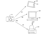
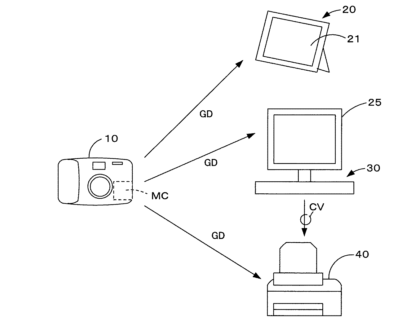
図1および図2を参照して本実施例に係る画像処理装置を含む画像処理システムについて説明する。図1は本実施例に係る画像処理装置を含む画像処理システムの概略構成を示す説明図である。図2は本実施例に係る画像処理装置の概略構成を示す説明図である。 An image processing system including an image processing apparatus according to this embodiment will be described with reference to FIGS. 1 and 2. FIG. 1 is an explanatory diagram illustrating a schematic configuration of an image processing system including an image processing apparatus according to the present embodiment. FIG. 2 is an explanatory diagram illustrating a schematic configuration of the image processing apparatus according to the present embodiment.
画像処理システムは、画像データ生成装置としてのディジタルスチルカメラ10、画像データGDに対する画像処理を実行する画像処理装置としての表示装置20、パーソナルコンピュータ30、カラープリンタ40を備えている。
The image processing system includes a digital
ディジタルスチルカメラ10は、光の情報をディジタルデバイス(CCDや光電子倍増管といった光電変換素子)に結像させることによりディジタル画像データを取得(生成)するカメラである。ディジタルスチルカメラ10は、例えば、各構成画素に対してR、G、Bの各フィルタが所定の規則に従って配置されたCCDを備え、被写体に対応したディジタル画像データを生成する。より具体的には、Rフィルタを有する画素においては、R成分の画素データを直接取得する他、周囲の画素データを基にしてG成分、B成分の画素データを補間演算によって生成する。生成された画像データは、記憶装置としてのメモリカードMCに保存される。ディジタルスチルカメラ10における画像データの保存形式としては、非可逆圧縮保存方式としてJPEGデータ形式、可逆圧縮保存方式としてTIFFデータ形式が一般的であるが、この他にもRAWデータ形式、GIFデータ形式、BMPデータ形式等の保存形式が用いられ得る。なお、画像データ生成装置としては、この他にもスキャナ等の撮像装置が用いられても良い。
The digital
表示装置20は、画像を表示するための表示ディスプレイ21を有する、例えば、電子式の写真フレームとして機能する表示装置であり、スタンドアローンにて後述するカラープリンタ40における画像処理と同等の画像処理を画像データに対して実行し、出力画像を表示する。表示装置20は、例えば、記憶媒体、赤外線通信および電波式通信といった無線通信を介して、あるいは、ケーブルを介してディジタルスチルカメラ10、ネットワーク上のサーバ(図示しない)から画像データを取得する。表示ディスプレイ21は、例えば、液晶表示ディスプレイ、有機EL表示ディスプレイであり、各表示ディスプレイパネル毎に独自の画像出力特性を有する。
The
パーソナルコンピュータ30は、例えば、汎用タイプのコンピュータであり、CPU、RAM、ハードディスク等を備えて、後述するカラープリンタ40における画像処理と同等の画像処理を実行する。パーソナルコンピュータ30は、この他にも、メモリカードMCを装着するためのメモリカードスロット、ディジタルスチルカメラ10等からの接続ケーブルを接続するための入出力端子を備えている。
The
カラープリンタ40は、カラー画像の出力が可能なプリンタであり、本実施例では、スタンドアローンにて、画像データに対する画像処理を実行して、画像を出力する。カラープリンタ40は、図2に示すように、制御回路41、入出力操作部42、印刷画像出力部43、メモリカードスロット44、データ入出力部45を備えている。
The
制御回路41は、画像データに対する画像処理、解析処理等の各種演算処理を実行する中央演算装置(CPU)411、画像処理が施された画像データ、演算結果等の各種データを一時的に格納するランダムアクセスメモリ(RAM)412、CPU111によって実行されるプログラム、画像を特徴付ける被写体である主要被写体を識別するための被写体判定条件の各パラメータを示すテーブル等を格納するリードオンリメモリ(ROM)/ハードディスクドライブ(HDD)413を備えている。
The
入力操作部42は、外部からの入力を受け付けるインターフェース部であり、例えば、キー操作部、スクロール操作部、タッチパネル式操作部として実現される。
The
印刷画像出力部43は、制御回路41から出力される印刷用画像データに基づいて、例えば、シアン(C)、マゼンタ(M)、イエロー(Y)、ブラック(K)の4色の色インクを印刷媒体上に噴射してドットパターンを形成することによって画像を形成するインクジェット方式の印刷画像出力部である。あるいは、カラートナーを印刷媒体上に転写・定着させて画像を形成する電子写真方式の印刷画像出力部である。色インクには、上記4色に加えて、ライトシアン(薄いシアン、LC)、ライトマゼンタ(薄いマゼンタ、LM)、ブルー、レッドを用いても良い。
The print
メモリカードスロット44は、各種メモリカードを装填するための装填部であり、メモリカードスロット14に装填されたメモリカードに対する読み出しまたは書き込みは、制御回路41によって実行される。
The
データ入出力部45は、接続ケーブルCV等が接続される端子、信号変換処理機能を有し、外部器機との間で画像データをやりとりするために用いられる。
The data input /
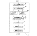
図3を参照してカラープリンタ40が備える制御回路41によって実現されるモジュールの概略について説明する。図3は本実施例に係るカラープリンタ40が備える制御回路41によって実現される機能モジュールのブロック図である。なお、図3に示す各モジュールは、CPU411単独で、あるいは制御回路41として実現され、また、ハードウェア、ソフトウェアのいずれによっても実現され得る。
With reference to FIG. 3, an outline of modules realized by the
画像データは、画像データ取得モジュールM1によって制御回路41に取得され、画像データ分割モジュールM2に送られる。
The image data is acquired by the
画像データ分割モジュールM2は、画像データを複数の領域(複数の画素データ群)に分割する。すなわち、画像を複数の領域に分割した際に得られる各領域に画像データを割り当てる。画像の各領域は1または複数の画素で構成されており、各領域に割り当てられる画像データの複数の領域はそれぞれ1または複数の画素データによって構成されている。テクスチャ特性取得モジュールM3は、画像データを領域単位にて解析し、各領域のテクスチャ特性を取得する。色域特性取得モジュールM4は、画像データを領域単位にて解析し、各領域の色域特性を取得する。なお、テクスチャ特性取得モジュールM3は、分散値取得モジュールとして実現されても良く、また、色域特性取得モジュールM4は、色域値取得モジュールとして実現されても良い。 The image data division module M2 divides the image data into a plurality of regions (a plurality of pixel data groups). That is, image data is assigned to each area obtained when an image is divided into a plurality of areas. Each area of the image is composed of one or a plurality of pixels, and each of the plurality of areas of the image data allocated to each area is composed of one or a plurality of pixel data. The texture characteristic acquisition module M3 analyzes the image data in units of areas and acquires the texture characteristics of each area. The color gamut characteristic acquisition module M4 analyzes the image data in units of areas and acquires the color gamut characteristics of each area. The texture characteristic acquisition module M3 may be realized as a dispersion value acquisition module, and the color gamut characteristic acquisition module M4 may be realized as a color gamut value acquisition module.
肌領域決定モジュールM5は、取得されたテクスチャ特性および色域特性を用いて画像データの各領域の内、肌領域に該当する領域を特定する。肌領域決定モジュールM5は、例えば、滑らかなテクスチャ特性を示すと共に肌色の色域特性を有する領域を肌領域と判別する。肌領域決定モジュールM5はさらに、同一の色域特性およびテクスチャ特性を示すと共に隣接する画像データの領域を関連付けて被写体領域を形成する被写体領域形成モジュールM51を備えても良い。この場合には、肌領域決定モジュールM5は、被写体領域単位にて、肌領域を決定する。 The skin area determination module M5 specifies an area corresponding to the skin area among the areas of the image data using the acquired texture characteristics and color gamut characteristics. The skin area determination module M5 determines, for example, an area that exhibits smooth texture characteristics and has a skin color gamut characteristic as a skin area. The skin region determination module M5 may further include a subject region forming module M51 that shows the same color gamut characteristics and texture properties and associates adjacent image data regions to form a subject region. In this case, the skin area determination module M5 determines the skin area in units of subject areas.
平滑化処理モジュールM6は、肌領域であると決定された画像データの各領域に対して、平滑化処理を実行する。画質調整モジュールM7は、領域単位にて平滑化処理が施された画像データに対して、画像データ全体を対象とする画質調整処理を実行する。画像出力モジュールM8は、画質調整が施された画像データを用いて出力画像を出力する。 The smoothing processing module M6 performs a smoothing process on each area of the image data determined to be a skin area. The image quality adjustment module M7 executes image quality adjustment processing for the entire image data on the image data that has been subjected to smoothing processing in units of regions. The image output module M8 outputs an output image using the image data that has undergone image quality adjustment.
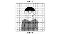
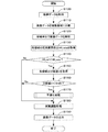
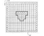
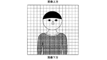
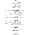
図4〜図7を参照して、本実施例に係る画像処理装置としてのカラープリンタ40にて実行される肌色領域判別処理について説明する。図4は処理対象となる画像の一例を模式的に示す説明図である。図5は本実施例に係るカラープリンタにおいて実行される肌領域判定処理の処理ルーチンを示すフローチャートである。図6は本実施例に係るカラープリンタにおいて実行される肌色領域の判定処理の過程を模式的に示す説明図である。図7は画像データの領域(画素データ群)の解析結果の一例を示す説明図である。
With reference to FIGS. 4 to 7, a skin color area determination process executed by the
本処理ルーチンの対象となる画像データGDは図4に示す画像に対応する画像データGDである。図4に示す画像は、肌領域(顔領域)にシミ、傷が存在する。以下の説明で用いる、画像上方、画像下方はそれぞれ図4に示す領域を指す。 The image data GD that is the target of this processing routine is the image data GD corresponding to the image shown in FIG. In the image shown in FIG. 4, there are spots and scratches in the skin area (face area). The upper and lower images used in the following description refer to the areas shown in FIG.
図5の処理ルーチンは、例えば、カラープリンタ40のメモリスロット44にメモリカードMCが差し込まれたとき、あるいは、ケーブルCVを介してカラープリンタ40にディジタルスチルカメラ10が接続されたときに開始される。
The processing routine of FIG. 5 is started, for example, when the memory card MC is inserted into the
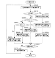
制御回路41(CPU411)は、画像処理を開始すると、選択された画像データGDを取得してRAM412に一時的に格納する(ステップS100)。一般的に、ディジタルスチルカメラ10において生成された画像データGDは、YCbCrデータであるため、CPU411は、選択された画像データGDが開かれるとYCbCrデータをRGBデータへと変換する。画像データGDの選択は、例えば、カラープリンタ40と有線または無線にて接続されているディジタルスチルカメラ10上において行われていても良く、あるいは、カラープリンタ40上において、メモリカードMCに格納されている画像データGDの中から選択されても良い。さらには、ネットワークを介してサーバ上に格納されている複数の画像データGDから選択されても良い。
When the image processing is started, the control circuit 41 (CPU 411) acquires the selected image data GD and temporarily stores it in the RAM 412 (step S100). In general, since the image data GD generated in the digital
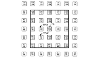
CPU411は、選択された画像データGDを図6に示すように複数の領域、例えば256(16×16)の領域(画素データ群)に分割する(ステップS110)。ただし、図6は説明を容易にするため画像データGDがメモリ上に展開された仮想状態を模式的に示している。具体的に説明すると、画像データGDは複数の画素データから構成されており、各画素データには、例えば、x−y座標で示される位置情報が割り振られている。そこで、位置情報を利用して、画像を複数の領域に分割した各領域と各領域に対応する画素データ群とを対応付けることで、図6に示すように画像の分割領域と画像データGDの仮想的な分割領域とを対応付けることができる。本実施例では更に、各領域に対して左上から右下に向かって1〜255の番号を付すことで、各領域を区別する。なお、各本明細書中では、画像の分割領域に併せて分割された画像データGDの分割単位を、画像データGDの領域または画素データ群という。
The
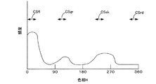
CPU411は、画像データGDを領域単位にて解析し(ステップS120)、画像データGDの各領域を構成する全画素データ数に対する肌色の色相を示す画素データ数の割合である肌色画素割合Hfl_rateを算出し(ステップS130)、取得した肌色画素割合Hfl_rateが画像データ領域の色相が肌色であると判別するための判定値Hfl_ref以上であるか否かを判定する(ステップS140)。具体的には、CPU411は、例えば、RGB画像データGDをHSV画像データに変換し、画像データの各領域単位にて、図7に示すような色相のヒストグラムを生成する。ここで、HSV色空間は、色相H、彩度S、輝度Vによって画像データGDを表す色空間である。画像データGDの色相Hは、この他にもHSL色空間へと画像データGDを変換することによっても得ることができる。RGB画像データGDをHSV画像データへと変換するにあたっては、R,G,B成分を有する各画素データに対して以下の式(1)〜(3)が適用される。また、肌色画素割合Hfl_rateの算出にあたっては、以下の式(4)が用いられる。なお、ここでは、説明を簡潔にするために色域のパラメータとして色相を用いる場合について説明する。
The
ここで、Vmax=max{R,G,B}、Vmin=min{R,G,B}である。Vmax=Vminの場合には、色相は不定(無彩色)となる。また、色相H<0の場合には、算出された色相Hに2πを加える。この結果、色相Hの値域は0〜2πとなるが、本実施例では、値域を0〜360度として色相Hを表す。 Here, Vmax = max {R, G, B} and Vmin = min {R, G, B}. When Vmax = Vmin, the hue is indefinite (achromatic). When the hue H <0, 2π is added to the calculated hue H. As a result, the range of the hue H is 0 to 2π, but in this embodiment, the hue H is expressed by setting the range to 0 to 360 degrees.
図7に示すヒストグラムにおいて、肌色に対応する色相域はCSfl、緑色に対応する色相域はCSgr、空色に対応する色相域はCSsk、赤色に対応する色相域はCSrdにてそれぞれ示されている。図7に例示するヒストグラムでは、肌色の色相が高い頻度で現れており、解析された画像データ領域が肌を中心とする被写体に対応するものであることが推察できる。 In the histogram shown in FIG. 7, the hue range corresponding to the skin color is indicated by CSfl, the hue range corresponding to green is CSgr, the hue range corresponding to sky blue is CSsk, and the hue range corresponding to red is indicated by CSrd. In the histogram illustrated in FIG. 7, the hue of the skin color appears frequently, and it can be inferred that the analyzed image data area corresponds to the subject centered on the skin.
CPU411は、肌色画素割合Hfl_rate≧判定値Hfl_refであると判定した場合には(ステップS140:Yes)、その画像データGDの領域の分散値Vを取得し(ステップS150)、取得した分散値Vが判定値Vref2未満であるか否かを判定する(ステップS160)。
When the
一方、CPU411は、肌色画素割合Hfl_rate<判定値Hfl_refであると判定した場合には(ステップS140:No)、対象となっている画像データ領域に対する平滑化処理を実行することなく、画質調整処理(ステップS180)へと移行する。
On the other hand, when the
分散値の算出方法について具体的に説明すると、CPU411は、各領域を構成する各画素データの分散値を輝度成分Y、色差成分Cb、Crについて算出し、最も大きな値を各領域の分散値Vとして採用する。分散値Vは以下の式(5)によって求められる。なお、式中xiは各画素データのY、Cb、Cr成分のいずれかを示し、xバーはY、Cb、Cr成分のそれぞれについての領域を構成する全画素データの平均値を示す。
The method for calculating the variance value will be described in detail. The
CPU411は、取得した分散値Vが分散判定値Vref2未満であると判定した場合には(ステップS160:Yes)、平滑化処理を実行する(ステップS170)。一方、CPU411は、取得した分散値Vが分散判定値Vref2以上であると判定した場合には(ステップS160:No)、対象となっている画像データ領域に対する平滑化処理を実行することなく画質調整処理(ステップS180)へと移行する。図6に示す例では、86〜91、102〜107、119〜122、135〜138および152,153の画像データ領域が肌領域に該当すると決定される。肌領域であると決定(判定)された各画像データ領域に対しては、以下の平滑化処理が実行される。
If the
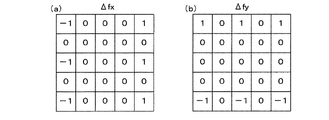
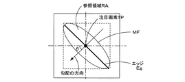
平滑化処理について図8〜図17を参照して説明する。図8は肌領域に対応する画像データの領域に対して実行される平滑化処理の処理ルーチンを示すフローチャートである。図9はエッジの勾配g(エッジ量)を求めるために用いられる3×3エッジ検出オペレータの一例を示す説明図である。図10はエッジの勾配g(エッジ量)を求めるために用いられる5×5エッジ検出オペレータの一例を示す説明図である。図11は、本実施例に係る画像処理装置において実行されるエッジを構成する画素に対して実行される平滑化処理の特徴を示す説明図である。図12は本実施例において用いられる参照画素抽出領域が方向性を有する楕円形メディアンフィルタを例示する説明図である。図13は図12に示す画像の画素値(輝度値、色差値)の分布を画素レベルにて例示的に示すと共に注目画素TPについて平滑化処理を行う際におけるメディアンフィルタの適用の様子を観念的に示す説明図である。図14は本実施例と従来例との平滑化処理の比較結果の一例を示す説明図である。図15は本実施例において用いられる9×9移動平均フィルタの一例を示す説明図である。図16は本実施例において用いられる17×17移動平均フィルタの一例を示す説明図である。図17は本実施例において用いられる21×21移動平均フィルタの一例を示す説明図である。図18は本実施例における平滑化処理の結果得られる出力画像を模式的に示す説明図である。 The smoothing process will be described with reference to FIGS. FIG. 8 is a flowchart showing a processing routine of the smoothing process executed for the image data area corresponding to the skin area. FIG. 9 is an explanatory diagram showing an example of a 3 × 3 edge detection operator used for obtaining the edge gradient g (edge amount). FIG. 10 is an explanatory diagram showing an example of a 5 × 5 edge detection operator used for obtaining the edge gradient g (edge amount). FIG. 11 is an explanatory diagram illustrating characteristics of the smoothing process executed on the pixels constituting the edge executed in the image processing apparatus according to the present embodiment. FIG. 12 is an explanatory diagram illustrating an elliptical median filter in which the reference pixel extraction region used in the present embodiment has directionality. FIG. 13 exemplarily shows the distribution of pixel values (luminance values, color difference values) of the image shown in FIG. 12 at the pixel level, and conceptually shows how the median filter is applied when the smoothing process is performed on the target pixel TP. It is explanatory drawing shown in. FIG. 14 is an explanatory diagram showing an example of a comparison result of the smoothing process between the present embodiment and the conventional example. FIG. 15 is an explanatory diagram showing an example of a 9 × 9 moving average filter used in this embodiment. FIG. 16 is an explanatory diagram showing an example of a 17 × 17 moving average filter used in this embodiment. FIG. 17 is an explanatory diagram showing an example of a 21 × 21 moving average filter used in this embodiment. FIG. 18 is an explanatory diagram schematically showing an output image obtained as a result of the smoothing process in the present embodiment.
CPU411は、平滑化処理(ノイズ低減処理)を開始すると、対象となる画像データ領域の色空間を輝度成分と色差成分とによって表される色座標系、例えば、YCbCr、Labへと変換する。本実施例では、YCbCrを例にとって説明する。本実施例では、既に扱っているデータがRGBデータであるから、CPU411は、以下の式を用いて対象となる画像データ領域に対してRGB−YCbCr変換を実行する。なお、上記色域の判定に際してYCbCrデータが用いられた場合には、特に変換処理は不要である。
Y=0.2999R+0.587G+0.114B
Cr=0.713(R−Y) Cb=0.564(B−Y)
When starting the smoothing process (noise reduction process), the
Y = 0.2999R + 0.587G + 0.114B
Cr = 0.713 (R−Y) Cb = 0.564 (B−Y)
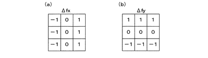
CPU411は、注目画素TPの勾配(エッジ量)gをY(輝度)、Cb、Cr(色差)の各成分について算出する(ステップS200)。エッジ量gを算出する手法は既にいくつかの手法が確立されており、本実施例では例えば、図9に示す3×3Prewittオペレータ、図10に示す5×5Prewittオペレータを用いて説明する。
The
CPU411は、注目画素TPの輝度成分をY(i,j)として表した場合、以下の式(6)、(7)を用いてΔfxおよびΔfyを算出する。式(6)、(7)は3×3Prewittオペレータを用いた場合の例である。
When the luminance component of the target pixel TP is expressed as Y (i, j), the
CPU411は、続いて以下の式(8)を用いてエッジ量gを算出する。
Subsequently, the
![]()
![]()
CPU411は、Cr成分、Cb成分のそれぞれについてもY成分と同様にしてエッジ量を求め、最も大きなエッジ量gを注目画素TPのエッジ量gとして採用する。なお、上記説明では、説明を容易にするため3×3Prewittオペレータを用いて説明したが、画像データを構成する画素数が増加している今日では、より正確なエッジ量gを求めるため図10に示す5×5Prewittオペレータを用いることが望ましい。
The
CPU411は、算出したエッジ量gが75以上であるか否かを判定し(ステップS210)、75≦gであると判定した場合には(ステップS210:Yes)、エッジ角度θを算出する(ステップS220)。CPU411は、先に求めたΔfxおよびΔfyを用いて以下の式(9)からエッジ角度を算出する。
The
ただし、式(8)によって実際に算出される角度θは、図11に示すように水平方向に対する勾配の方向θであり、厳密な意味でのエッジ角度ではない。ただし、勾配の方向はエッジの方向に対して垂直(90°)に交差するため、勾配の方向θとエッジの方向(エッジ角度)とは一義的に対応付けられており、勾配の方向θを求めることでエッジ角度を求めることができる。 However, the angle θ actually calculated by the equation (8) is the gradient direction θ with respect to the horizontal direction as shown in FIG. 11, and is not an edge angle in a strict sense. However, since the gradient direction intersects perpendicularly (90 °) with respect to the edge direction, the gradient direction θ and the edge direction (edge angle) are uniquely associated with each other. The edge angle can be obtained by obtaining.
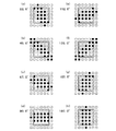
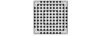
CPU411は、算出した勾配の方向θに基づいて画像上のエッジ角度に適したメディアンフィルタを取得する(ステップS222)。カラープリンタ40のROM/HDD413には、予め図12(a)〜(h)に示すような、参照領域RAに方向性を持った(参照画素をエッジ周囲の画素に絞った)メディアンフィルタMFが格納されており、CPU411は、算出した勾配の方向θを指標として画像上のエッジ角度に適したメディアンフィルタMFを選択する。本実施例では、0°〜180°の範囲で22.5°刻みにて8種類の方向性を有するメディアンフィルタMFが用意されている。
The
図12中、黒塗りの四角は参照画素を示し、白色の画素は非参照画素を示し、−画素は注目画素として取り扱われない(平滑化の対照とならない)スキップ画素を意味する。図12中に示す角度は勾配の方向θを示しており、メディアンフィルタMFが有する方向性(実際に画像上に形成されている角度)を示すものではない。すなわち、既述のように勾配の方向θと現実のエッジ角度(方向)とは90°ずれており、本実施例ではこの相違を考慮した上で勾配の方向θを指標として画像上のエッジ角度に適したメディアンフィルタMFを選択できるよう予め勾配の方向θと画像上のエッジ角度とを対応付けている。 In FIG. 12, a black square indicates a reference pixel, a white pixel indicates a non-reference pixel, and a -pixel means a skip pixel that is not treated as a target pixel (not a smoothing contrast). The angle shown in FIG. 12 indicates the gradient direction θ and does not indicate the directionality (the angle actually formed on the image) of the median filter MF. That is, as described above, the gradient direction θ and the actual edge angle (direction) are shifted by 90 °. In this embodiment, the difference is taken into account, and the edge angle on the image is determined using the gradient direction θ as an index. The gradient direction θ and the edge angle on the image are associated in advance so that the median filter MF suitable for the image can be selected.
図12には、説明の都合上、9×9の角度付きメディアンフィルタMFが例示されているが、実際の処理においては17×17の角度付きメディアンフィルタMFを用いることが好ましい。 FIG. 12 illustrates a 9 × 9 angled median filter MF for convenience of explanation, but it is preferable to use a 17 × 17 angled median filter MF in actual processing.
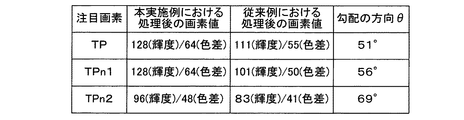
CPU411は、取得したメディアンフィルタMFを用いて平滑化処理を実行する(ステップS224)。この平滑化処理では、色差成分であるCr,Cbおよび輝度成分Yについて平滑化処理を実行する。例えば、図11に示すエッジを有する画像が図13に示す画素値(色彩値および輝度値)分布を有する場合について説明すると、注目画素TPの勾配の方向θは51°となるため、図12(b)に示す45.0°のメディアンフィルタMFを選択してメディアンフィルタ演算を実行する。
The
図13において注目画素はTP、TPn1、TPn2によって表され、参照画素は斜線付きの四角で示され、非参照画素は白抜きの四角にて示されている。また、図中の数値は(輝度値/色差値)を示している。さらに、各四角の間には画素が存在するが、画像処理速度を向上させるためにこれら画素は、注目画素、参照画素として取り扱われないスキップ画素であるから表示を省略した。 In FIG. 13, the target pixel is represented by TP, TPn1, and TPn2, the reference pixel is indicated by a hatched square, and the non-reference pixel is indicated by a white square. The numerical values in the figure indicate (luminance value / color difference value). Further, although pixels exist between the squares, in order to improve the image processing speed, these pixels are skipped pixels that are not handled as the target pixel and the reference pixel, and thus the display is omitted.
注目画素TPの色彩値または輝度値および斜線で示されている参照画素の色差値および輝度値を用いて各中央値が算出され、平滑化処理後の注目画素TPの色彩値となる処理後輝度値および色差値(処理後色彩値)が得られる。CPU411は演算により得られた処理後色彩値をRAM412に一時的に格納する。
The post-processing luminance that is calculated as the median value using the color value or luminance value of the target pixel TP and the color difference value and luminance value of the reference pixel indicated by diagonal lines and becomes the color value of the target pixel TP after smoothing processing Values and color difference values (processed color values) are obtained. The
注目画素TPは当初、255の輝度値、127の色差値を示し、周りの画素の色差値および輝度値を参照すると、例えば、大きなしわといったエッジ成分を示している可能性が高い。従来の移動平均フィルタを用いた場合には、枠線内の全ての画素の色差値および輝度値が参照されるため、注目画素TPの処理後の輝度値および色差値は、図14に示すように、111および55となり平滑化処理によってエッジ成分が損なわれてしまう。 The target pixel TP initially shows a luminance value of 255 and a color difference value of 127, and when referring to the color difference value and luminance value of surrounding pixels, there is a high possibility that it indicates an edge component such as a large wrinkle. When the conventional moving average filter is used, since the color difference values and luminance values of all the pixels in the frame line are referred to, the luminance values and color difference values after processing of the target pixel TP are as shown in FIG. Furthermore, the edge components are impaired by the smoothing process.
これに対して、角度付きメディアンフィルタMFを用いる本実施例における平滑化処理では、図14に示すように、色差値および輝度値を用いて得られる注目画素TPの処理後の色差値および輝度値はそれぞれ128および64となるため、エッジ成分を損なうことなくノイズを低減することができる。また、参照領域RAをエッジ角度(エッジ形成方向)に一致させて、エッジ形成画素を覆うようにして平滑化処理(メディアンフィルタ演算)を実行するので、通常、長い演算時間が要求されるメディアンフィルタ演算の演算時間を短縮しつつ、エッジ成分を損なうことのない精度の高いノイズ低減処理を実行することができる。 On the other hand, in the smoothing process in the present embodiment using the angled median filter MF, as shown in FIG. 14, the color difference value and the luminance value after processing of the target pixel TP obtained using the color difference value and the luminance value. Is 128 and 64, respectively, so that noise can be reduced without impairing the edge component. In addition, since the smoothing process (median filter calculation) is performed so that the reference area RA coincides with the edge angle (edge forming direction) and covers the edge forming pixels, a median filter that normally requires a long calculation time is performed. It is possible to execute a highly accurate noise reduction process that does not impair the edge component while shortening the calculation time of the calculation.
CPU411は、ステップS210にて注目画素TPのエッジ量gが75未満であると判断した場合には(ステップS210:No)、移動平均フィルタを用いた平滑化処理を実行する。一般的に、分散値Vが大きい場合には、対象領域の画像に高周波成分、すなわちテクスチャ成分が多く含まれていることを意味し、分散値Vが小さな場合には、対象領域の画像には高周波成分(テクスチャ成分)が余り含まれていないことを意味する。換言すれば、分散値Vが小さい場合には、対象領域の画像は滑らかであり、分散値Vが大きい場合には対象領域の画像は粗いことを意味する。したがって、分散値Vが大きくなるにつれてサイズの小さな移動平均フィルタを用いた平滑化処理を以下、実行する。
If the
CPU411は、分散値Vが200より大きいか否かを判定し(ステップS230)、分散値Vが200より大きいと判定した場合には(ステップS230:Yes)、図15に示す9×9の移動平均フィルタ、すなわち9×9の範囲内に参照画素を有する参照領域の小さな移動平均フィルタを用いて注目画素TPに対する平滑化処理を実行する(ステップS232)。CPU411は演算により得られた処理後色彩値をRAM412に一時的に格納する。処理後色彩値は、例えば、注目画素TPからの距離に応じて各参照画素の色彩値(色差値および輝度値)に重み係数を乗算したものの総和をとり、総和を参照画素数で除算することによって得られる。
The
図15においても黒塗りの四角は参照画素を示し、白抜きの四角は非参照画素を示し、−の表示はスキップ画素を示している。本実施例において用いられる移動平均フィルタは、本来ガウス分布に対応した参照領域を有するので四つ角の画素も参照画素として採用すべきであるが、演算処理時間を短縮するため、経験則上、平滑化処理に大きな影響を及ぼさない四つ角の画素は非参照画素としている Also in FIG. 15, black squares indicate reference pixels, white squares indicate non-reference pixels, and − indicates a skip pixel. Since the moving average filter used in this embodiment originally has a reference region corresponding to a Gaussian distribution, a quadrangular pixel should also be adopted as a reference pixel. However, in order to shorten the calculation processing time, smoothing is performed according to empirical rules. Pixels with four corners that do not significantly affect processing are set as non-reference pixels
CPU411は、分散値Vが200以下であると判定した場合には(ステップS230:No)、分散値Vが50より大きいか否かを判定する(ステップS240)。CPU411は、分散値Vが50より大きいと判定した場合には(ステップS240:Yes)、図16に示す中間の大きさの参照領域を有する17×17の移動平均フィルタを用いて注目画素TPに対する平滑化処理を実行する(ステップS242)。CPU411は演算により得られた処理後色彩値をRAM412に一時的に格納する。図16における黒塗りの四角、白抜きの四角、−の表示は既述の通りの意味を有する。
When determining that the variance value V is 200 or less (step S230: No), the
CPU411は、分散値Vが50以下であると判定した場合には(ステップS240:No)、図17に示す参照領域の大きな21×21の移動平均フィルタを用いて注目画素TPに対する平滑化処理を実行する(ステップS250)。CPU411は演算により得られた処理後色彩値をRAM412に一時的に格納する。かかる場合には、注目画素TPの周囲に、例えば、肌を表す比較的一様な画素が含まれていることを意味するので、参照領域の大きなフィルタを用いることによって平均化の度合いを上げて、平滑化に重きを置いた強力な平滑化処理を実行する。図17における黒塗りの四角、白抜きの四角、−の表示は既述の通りの意味を有する。
When the
CPU411は、今回の注目画素TPに対して、以上説明したいずれかの平滑化処理を終えると、対象となっている画像データ領域の全画素(スキップ画素を除く)に対する平滑化処理が終了したか否かを判定し(ステップS260)、全画素(スキップ画素を除く)について平滑化処理が終了していないと判定した場合には(ステップS260:No)、注目画素TPを変更して(ステップS270)、ステップ200に戻り、次の注目画素TPに対して上記の平滑化処理を実行する。一方、CPU411は、対象となっている画像データ領域の全画素(スキップ画素を除く)について平滑化処理が終了したと判定した場合には(ステップS260:Yes)、本平滑化処理を終了する。上記平滑化処理によって、例えば、図18に示すように、シミ、傷が目立たなくなり、一方で、鼻、大きなしわのぼけを防止することができる。
When the
CPU411はRAM412に一時的に格納された各画素データについての処理後色彩値を対応する各画素データの新たな色彩値とし、YCbCrデータをRGBデータに変換する。
The
図5に戻り説明を続けると、CPU411は、画像データの全領域に対して、あるいは、各領域単位にて、他の画質調整処理を実行し(ステップS180)、データ変換処理部、例えば、プリンタドライバに出力して(ステップS190)、本処理ルーチンを終了する。プリンタドライバ(CPU411)は、RGBデータをプリンタの色空間に併せてCMYKデータへと変換し、ハーフトーン処理等の必要な処理を行った後、例えば、ラスタデータとして印刷画像出力部43へ出力する。
Returning to FIG. 5 and continuing the description, the
以上説明したとおり、本実施例に係る画像処理装置としてのカラープリンタ40によれば、画像データを複数の領域に分割し、各画像データ領域毎に色彩値と分散(テクスチャ特性)とを用いて肌領域に該当するか否かが判定される。したがって、肌領域を精度良く判定することができる。すなわち、各画像データ領域の色域が肌色の色域に含まれると共に、各画像データ領域が滑らかである場合に、その画像データ領域を肌領域であると判定するので、肌色に近似する色域を有する粗い被写体(領域)、例えば、ピンク色のセーターを肌領域であると誤判定することを防止または抑制することができる。
As described above, according to the
さらに、本実施例に係るカラープリンタ40によれば、肌領域であると特定した画像データ領域に対て平滑化処理を実行するので、肌領域に存在するシミ、傷といった忠実に再現されることが望まれない部分を消去または低減することができる。したがって、美しい肌領域を有する出力画像を得ることができる。また、肌領域の判定精度の向上と相まって、肌領域でない領域に対する平滑化処理を防止することが可能となる。
Furthermore, according to the
・その他の実施例:
(1)上記実施例では、複数の画素データから構成される領域単位にて平滑化処理の有無を判定し、また、平滑化処理が行われているが、図19に示すように、画素データ単位にて平滑化処理の有無を判定し、平滑化処理を行っても良い。図19は他の実施例に係るカラープリンタにおいて実行される肌領域判定処理の処理ルーチンを示すフローチャートである。
Other examples:
(1) In the above embodiment, the presence / absence of the smoothing process is determined for each region composed of a plurality of pixel data, and the smoothing process is performed. As shown in FIG. The presence or absence of the smoothing process may be determined in units, and the smoothing process may be performed. FIG. 19 is a flowchart illustrating a processing routine for skin area determination processing executed in a color printer according to another embodiment.
図19の処理ルーチンは、例えば、カラープリンタ40のメモリスロット44にメモリカードMCが差し込まれたとき、あるいは、ケーブルCVを介してカラープリンタ40にディジタルスチルカメラ10が接続されたときに開始される。なお、図5におけるステップと同等のステップについては簡単に説明を行う。
The processing routine of FIG. 19 is started, for example, when the memory card MC is inserted into the
制御回路41(CPU411)は、画像処理を開始すると、選択された画像データGDを取得してRAM412に一時的に格納する(ステップS300)。図5におけるステップS100と同様の処理である。 When starting the image processing, the control circuit 41 (CPU 411) acquires the selected image data GD and temporarily stores it in the RAM 412 (step S300). This is the same processing as step S100 in FIG.
CPU411は、選択された画像データGDに含まれる対象画素データを特定する(ステップS310)。対象画素データの特定は、画像データGDを構成する全画素データに対して実行されても良く、あるいは、画像データGDを構成する全画素データから1〜数画素おきに選択された画素データで構成されている間引き画像データに対して実行されても良い
The
CPU411は、特定された対象画素データが肌色の色彩値を示すか否かを判断し(ステップS320)、肌色の色彩値を示さないと判定した場合には(ステップS320:No)、ステップS360に移行する。対象画素データが肌色の色彩値を有するか否かの判定は、対象画素データが示すRGB成分に基づいて行われても良く、あるいは、上述のように対象画素データが示すRGB成分をHSV成分へと変換して、色相Hに基づいて行われても良い。
The
CPU411は、特定された対象画素データが肌色の色彩値を示すと判定した場合には(ステップS320:Yes)、対象画素データの周辺画素データを参照して分散値Vを取得する(ステップS330)。CPU411は、取得した分散値Vが判定値Vref2未満であるか否かを判定する(ステップS340)。なお、分散値の算出に当たっては、画像データを構成する全ての画素データが用いられる。また、分散値の算出方法は、既述の通りである。
When the
CPU411は、取得した分散値Vが分散判定値Vref2未満であると判定した場合には(ステップS340:Yes)、平滑化処理を実行する(ステップS350)。なお、平滑化処理については説明済みであるから説明を省略する。一方、CPU411は、取得した分散値Vが分散判定値Vref2以上であると判定した場合には(ステップS340:No)、対象となっている画像データ領域に対する平滑化処理を実行することなくステップS360に移行する。
When the
CPU411は、ステップS360において、処理対象とすべき全ての画素データに対してステップS310〜ステップS350の処理が完了した否かを判定し、処理対象とすべき全ての画素データに対する上記処理が完了していないと判定した場合には(ステップS360:No)、次の対象画素データを特定し、ステップS320〜ステップS350を実行する。
In step S360, the
CPU411は、処理対象とすべき全ての画素データに対する上記処理が完了したと判定した場合には(ステップS360:Yes)、他の画質調整処理を実行し(ステップS370)、データ変換処理部、例えば、プリンタドライバに出力して(ステップS380)、本処理ルーチンを終了する。プリンタドライバ(CPU411)は、RGBデータをプリンタの色空間に併せてCMYKデータへと変換し、ハーフトーン処理等の必要な処理を行った後、例えば、ラスタデータとして印刷画像出力部43へ出力する。
If the
上記処理によって平滑化処理の有無を判定し、必要に応じて平滑化処理を実行する場合には、画素データ単位で実行されるので平滑化処理の有無の判断処理を高速化することができる。 When the presence or absence of the smoothing process is determined by the above process and the smoothing process is executed as necessary, the determination process of the presence or absence of the smoothing process can be speeded up because the process is executed in units of pixel data.
(2)上記実施例では、画像データ領域の色彩値が肌色の色域に含まれているか否かの判定をHCV色空間において実行したが、RGB色空間またはYCbCr色空間にて実行されてもよい。かかる場合には、画像データ領域のRGB成分が肌色RGB値域に含まれるか否か、あるいは、色差成分Cb、Crが肌色の色差を示しているか否かによって判断される。 (2) In the above embodiment, the determination whether or not the color value of the image data area is included in the flesh color gamut is performed in the HCV color space. However, even if it is performed in the RGB color space or the YCbCr color space. Good. In such a case, the determination is made based on whether or not the RGB component of the image data area is included in the skin color RGB value range, or whether or not the color difference components Cb and Cr indicate a skin color difference.
(3)上記実施例では、平滑処理時における色差成分と輝度成分の双方の変化特性を考慮した同一の判定分散値を用いて、色差と輝度の双方について同時に平滑化処理が実行されているが、色差に対する平滑化処理と輝度に対する平滑化処理とを別々に実行してもよい。かかる場合には、色差についての判定分散値と輝度についての判定分散値をそれぞれ用意することによって、平滑処理による色差の変化特性、輝度の変化特性を個々に反映した平滑化処理を実行することができる。したがって、平滑化処理によって得られる画像の見栄えを向上させることができる。 (3) In the above-described embodiment, the smoothing process is simultaneously performed for both the color difference and the luminance using the same determination variance value considering the change characteristics of both the color difference component and the luminance component during the smoothing process. The smoothing process for the color difference and the smoothing process for the luminance may be performed separately. In such a case, by preparing a determination variance value for the color difference and a determination variance value for the luminance, smoothing processing that individually reflects the color difference change characteristic and the luminance change characteristic by the smoothing process may be executed. it can. Therefore, the appearance of the image obtained by the smoothing process can be improved.
(4)上記実施例では、肌領域の特定を、各画像データ領域単位にて実行しているが、同一色彩値および分散値を有する隣接領域を関連付けて被写体領域を形成し、形成した被写体領域単位にて肌領域の特定が行われても良い。かかる場合には、被写体領域の大きさを考慮することによって、肌領域に該当する画像データ領域が集合してなる顔領域の判定精度を更に向上させることができる。 (4) In the above embodiment, the skin area is specified for each image data area, but the subject area is formed by associating adjacent areas having the same color value and variance value, and the formed subject area The skin area may be specified in units. In such a case, by considering the size of the subject region, it is possible to further improve the determination accuracy of the face region formed by a collection of image data regions corresponding to the skin region.
(5)上記実施例では、肌領域に該当する画像データ領域に対する平滑化処理に際して、メディアンフィルタと移動平均フィルタとを使い分けているが、移動平均フィルタのみを用いても良い。この場合には、大きな参照領域を有する移動平均フィルタが用いられることが好ましい。 (5) In the above embodiment, the median filter and the moving average filter are separately used in the smoothing process for the image data area corresponding to the skin area, but only the moving average filter may be used. In this case, it is preferable to use a moving average filter having a large reference area.
(6)上記実施例では、画像処理装置として、カラープリンタ40が用いられているが、この他にも、表示装置20、パーソナルコンピュータ30が用いられても良い。かかる場合にも上記実施例と同等の効果を得ることができる。
(6) In the above embodiment, the
(7)上記実施例では、画像処理がソフトウェア的に、すなわちコンピュータプログラムの態様にて実行されているが、上記各処理(ステップ)を実行する論理回路を備えた画像処理ハードウェア回路を用いて実行されてもよい。かかる場合には、411の負荷を軽減することができると共に、より高速な各処理を実現することができる。画像処理ハードウェア回路は、例えば、表示装置20およびカラープリンタ40に対しては実装回路として、パーソナルコンピュータ30に対してはアドオンカードとして実装され得る。
(7) In the above embodiment, image processing is executed in software, that is, in the form of a computer program, but using an image processing hardware circuit including a logic circuit that executes each of the above processes (steps). May be executed. In such a case, the load of 411 can be reduced, and each process at higher speed can be realized. For example, the image processing hardware circuit can be mounted as a mounting circuit for the
以上、実施例に基づき本発明に係る画像処理装置、画像処理方法および画像処理プログラムを説明してきたが、上記した発明の実施の形態は、本発明の理解を容易にするためのものであり、本発明を限定するものではない。本発明は、その趣旨並びに特許請求の範囲を逸脱することなく、変更、改良され得ると共に、本発明にはその等価物が含まれることはもちろんである。 As described above, the image processing apparatus, the image processing method, and the image processing program according to the present invention have been described based on the embodiments. However, the embodiment of the present invention described above is for facilitating the understanding of the present invention. It is not intended to limit the invention. The present invention can be changed and improved without departing from the spirit and scope of the claims, and it is needless to say that the present invention includes equivalents thereof.
10…ディジタルスチルカメラ
20…表示装置
25…表示ディスプレイ
30…パーソナルコンピュータ
31…表示ディスプレイ
40…カラープリンタ
41…制御回路
411…中央演算装置(CPU)
412…ランダムアクセスメモリ(RAM)
413…ハードディスク(HDD)/ROM
42…入力操作部
43…印刷画像出力部
44…メモリカードスロット
45…データ入出力部
MC…メモリカード
GD…画像データ
DESCRIPTION OF
412: Random access memory (RAM)
413: Hard disk (HDD) / ROM
42 ...
Claims (13)
判定の対象となる画像のデータである画像データを取得する画像データ取得手段と、
前記画像を複数の領域に分割した際の各領域に対応して前記画像データを複数の画像データ領域に分割する画像データ分割手段と、
前記画像データを前記画像データ領域単位にて解析し、前記各画像データ領域が示す色域特性を取得する色域特性取得手段と、
前記画像データを前記画像データ領域単位にて解析し、前記各画像データ領域が示すテクスチャ特性を取得するテクスチャ特性取得手段と、
前記取得された色域特性とテクスチャ特性とを用いて前記各画像データ領域の中で肌領域に該当する画像データ領域を特定する肌領域特定手段とを備える画像処理装置。 An image processing device for identifying a skin region in an image,
Image data acquisition means for acquiring image data that is image data to be determined;
Image data dividing means for dividing the image data into a plurality of image data areas corresponding to each area when the image is divided into a plurality of areas;
Analyzing the image data in units of the image data area, and obtaining a color gamut characteristic acquisition means for acquiring a color gamut characteristic indicated by each image data area;
Analyzing the image data in units of the image data area, and obtaining a texture characteristic acquisition means for acquiring a texture characteristic indicated by each image data area;
An image processing apparatus comprising: a skin area specifying unit that specifies an image data area corresponding to a skin area among the image data areas using the acquired color gamut characteristics and texture characteristics.
前記肌領域特定手段は、肌色の色域特性を示すと共に滑らかなテクスチャ特性を示す画像データ領域を肌領域に該当する画像データ領域として特定する画像処理装置。 The image processing apparatus according to claim 1.
The said skin area | region identification means is an image processing apparatus which specifies the image data area which shows the color gamut characteristic of skin color, and shows a smooth texture characteristic as an image data area applicable to a skin area | region.
前記肌領域特定手段はさらに、
同一の色域特性およびテクスチャ特性を示す隣接画像データ領域を関連付けて被写体領域を形成する被写体領域形成手段を備え、
前記肌領域特定手段は、前記形成された被写体領域のうち、肌色の色域特性を示すと共に滑らかなテクスチャ特性を示す被写体領域を特定することによって肌領域に該当する前記画像データ領域を特定する画像処理装置。 The image processing apparatus according to claim 1.
The skin region specifying means further includes
Subject area forming means for forming subject areas by associating adjacent image data areas exhibiting the same color gamut characteristics and texture characteristics;
The skin area specifying means specifies an image data area corresponding to a skin area by specifying a subject area that exhibits a skin color gamut characteristic and a smooth texture characteristic among the formed subject areas. Processing equipment.
前記色域特性は色相、彩度、明度をパラメータに含み、
前記テクスチャ特性は分散をパラメータに含み、
前記各画像データ領域は複数の画素データから構成され、
前記肌領域特定手段は、画像データ領域における全画素データ数に対する肌色の色域を示す画素データ数の割合が色域判定値以上である場合にその画像データ領域の色域特性が肌色を示すと判定し、画像データ領域における前記分散の値が分散判定値よりも低い場合にその画像データ領域のテクスチャ特性が滑らかであると判定する画像処理装置。 The image processing apparatus according to claim 2 or 3,
The color gamut characteristics include hue, saturation, and brightness as parameters,
The texture characteristic includes variance as a parameter,
Each of the image data areas is composed of a plurality of pixel data,
When the ratio of the number of pixel data indicating the skin color gamut to the total number of pixel data in the image data area is equal to or greater than the color gamut determination value, the skin area specifying unit indicates that the color gamut characteristic of the image data area indicates skin color An image processing apparatus that determines and determines that the texture characteristic of the image data area is smooth when the value of the dispersion in the image data area is lower than the dispersion determination value.
前記決定された肌領域に該当する画像データ領域に対して、平滑化処理を実行する平滑化処理手段を備える画像処理装置。 The image processing apparatus according to any one of claims 1 to 4, further comprising:
An image processing apparatus comprising smoothing processing means for executing a smoothing process on an image data area corresponding to the determined skin area.
前記各領域は1の画素で構成されており、前記各領域に対応する前記複数の画像データ領域は1の画素データで構成されている画像処理装置。 The image processing apparatus according to claim 1.
The image processing apparatus is configured such that each area includes one pixel, and the plurality of image data areas corresponding to each area include one pixel data.
前記各領域は複数の画素で構成されており、前記各領域に対応する前記複数の画像データ領域は複数の画素データで構成されている画像処理装置。 The image processing apparatus according to claim 1.
The image processing apparatus is configured such that each area includes a plurality of pixels, and the plurality of image data areas corresponding to the areas include a plurality of pixel data.
複数の画素データから構成される画像データを取得する画像データ取得手段と、
前記画像データを複数の画素データ群に分割する画像データ分割手段と、
前記画像データを画素データ群単位にて解析し、前記各画素データ群における、全画素データ数に対する肌色の色域を示す画素データ数の割合を色彩値として取得する色彩値取得手段と、
前記画像データを画素データ群単位にて解析し、前記各画素データ群が示す分散値を取得する分散値取得手段と、
前記取得された色彩値と分散値とを用いて前記各画素データ群の中から肌領域に対応する画素データ群を特定する肌色領域特定手段とを備える画像処理装置。 An image processing apparatus for identifying a skin area,
Image data acquisition means for acquiring image data composed of a plurality of pixel data;
Image data dividing means for dividing the image data into a plurality of pixel data groups;
Analyzing the image data in units of pixel data groups, color value acquisition means for acquiring, as a color value, a ratio of the number of pixel data indicating a skin color gamut to the total number of pixel data in each pixel data group;
Analyzing the image data in units of pixel data groups, and a dispersion value acquisition means for acquiring a dispersion value indicated by each pixel data group;
An image processing apparatus comprising: a skin color area specifying unit that specifies a pixel data group corresponding to a skin area from each of the pixel data groups using the acquired color value and variance value.
前記肌領域特定手段は、前記色彩値が色域判定値以上であると共に前記分散値が分散判定値よりも小さい画素データ群を肌領域とする画像処理装置。 The image processing apparatus according to claim 8.
The skin region specifying unit is an image processing apparatus in which a pixel data group in which the color value is greater than or equal to a color gamut determination value and the variance value is smaller than the variance determination value is a skin region.
前記肌領域特定手段はさらに、
同一の色彩値および分散値を示す隣接画素データ群を関連付けて被写体領域を形成する被写体領域形成手段を備え、
前記肌領域特定手段は、前記形成された被写体領域のうち、被写体領域に含まれる肌色の色域に含まれる画素データ数の割合が色域判定値以上であると共に分散判定値よりも小さな分散値を有する被写体領域を特定することによって肌領域に該当する前記画素データ群を特定する画像処理装置。 The image processing apparatus according to claim 8.
The skin region specifying means further includes
A subject area forming unit that forms a subject area by associating adjacent pixel data groups having the same color value and variance value;
The skin area specifying unit is configured such that a ratio of the number of pixel data included in the skin color gamut included in the subject area of the formed subject area is equal to or greater than a color gamut determination value and smaller than a dispersion determination value. An image processing apparatus that identifies the pixel data group corresponding to a skin region by identifying a subject region having a point.
前記決定された肌領域に該当する画素データ群に対して、平滑化処理を実行する平滑化処理手段を備える画像処理装置。 The image processing apparatus according to any one of claims 8 to 10, further comprising:
An image processing apparatus comprising smoothing processing means for executing a smoothing process on a pixel data group corresponding to the determined skin region.
判定の対象となる画像のデータである画像データを取得し、
前記画像を複数の領域に分割した際の各領域に対応して前記画像データを複数の画像データ領域に分割し、
前記画像データを前記画像データ領域単位にて解析して、前記各画像データ領域が示す色域特性を取得し、
前記画像データを前記画像データ領域単位にて解析して、前記各画像データ領域が示すテクスチャ特性を取得し、
前記取得し色域特性とテクスチャ特性とを用いて前記各画像データ領域の中で肌領域に該当する画像データ領域を特定する画像処理方法。 An image processing method for specifying a skin area in an image,
Obtain image data that is the image data to be judged,
The image data is divided into a plurality of image data areas corresponding to each area when the image is divided into a plurality of areas,
Analyzing the image data in units of the image data area, obtaining color gamut characteristics indicated by the image data areas,
Analyzing the image data in units of the image data area, obtaining texture characteristics indicated by the image data areas,
An image processing method for specifying an image data area corresponding to a skin area among the image data areas using the acquired color gamut characteristics and texture characteristics.
複数の画素データから構成される画像データを取得し、
前記画像データを複数の画素データ群に分割し、
前記画像データを画素データ群単位にて解析して、前記各画素データ群における、全画素データ数に対する肌色の色域を示す画素データ数の割合を色彩値として取得し、
前記画像データを画素データ群単位にて解析して、前記各画素データ群が示す分散値を取得し、
前記取得した色彩値と分散値とを用いて前記各画素データ群の中から肌領域に対応する画素データ群を特定する画像処理方法。 An image processing method for specifying a skin area,
Obtain image data consisting of multiple pixel data,
Dividing the image data into a plurality of pixel data groups;
Analyzing the image data in units of pixel data groups, in each pixel data group, to obtain the ratio of the number of pixel data indicating the skin color gamut with respect to the total number of pixel data as a color value,
Analyzing the image data in units of pixel data groups, obtaining a variance value indicated by each pixel data group,
An image processing method for specifying a pixel data group corresponding to a skin region from each of the pixel data groups using the acquired color value and variance value.
Priority Applications (3)
| Application Number | Priority Date | Filing Date | Title |
|---|---|---|---|
| JP2005038020A JP2005293555A (en) | 2004-03-10 | 2005-02-15 | Identification of skin area in image |
| US11/076,420 US7720279B2 (en) | 2004-03-10 | 2005-03-08 | Specifying flesh area on image |
| US12/799,194 US20100208946A1 (en) | 2004-03-10 | 2010-04-19 | Specifying flesh area on image |
Applications Claiming Priority (2)
| Application Number | Priority Date | Filing Date | Title |
|---|---|---|---|
| JP2004066575 | 2004-03-10 | ||
| JP2005038020A JP2005293555A (en) | 2004-03-10 | 2005-02-15 | Identification of skin area in image |
Publications (1)
| Publication Number | Publication Date |
|---|---|
| JP2005293555A true JP2005293555A (en) | 2005-10-20 |
Family
ID=35187159
Family Applications (1)
| Application Number | Title | Priority Date | Filing Date |
|---|---|---|---|
| JP2005038020A Withdrawn JP2005293555A (en) | 2004-03-10 | 2005-02-15 | Identification of skin area in image |
Country Status (2)
| Country | Link |
|---|---|
| US (2) | US7720279B2 (en) |
| JP (1) | JP2005293555A (en) |
Cited By (4)
| Publication number | Priority date | Publication date | Assignee | Title |
|---|---|---|---|---|
| JP2008192138A (en) * | 2007-02-01 | 2008-08-21 | Toshiba Corp | System and method for correcting facial area of image |
| JP2009147937A (en) * | 2007-12-13 | 2009-07-02 | Thomson Licensing | Method of generating distance indicating edge direction in video picture, corresponding device, and use of method for deinterlace or format conversion |
| JP2009252243A (en) * | 2008-04-04 | 2009-10-29 | Nhn Corp | Adult object determination method and system |
| US20210358172A1 (en) * | 2017-02-20 | 2021-11-18 | Henkel Ag & Co. Kgaa | Method and device for determining the homogeneity of skin color |
Families Citing this family (45)
| Publication number | Priority date | Publication date | Assignee | Title |
|---|---|---|---|---|
| JP4066803B2 (en) * | 2002-12-18 | 2008-03-26 | 株式会社ニコン | Image processing apparatus, image processing program, image processing method, and electronic camera |
| US8111265B2 (en) | 2004-12-02 | 2012-02-07 | Sharp Laboratories Of America, Inc. | Systems and methods for brightness preservation using a smoothed gain image |
| US9083969B2 (en) | 2005-08-12 | 2015-07-14 | Sharp Laboratories Of America, Inc. | Methods and systems for independent view adjustment in multiple-view displays |
| US7782405B2 (en) | 2004-12-02 | 2010-08-24 | Sharp Laboratories Of America, Inc. | Systems and methods for selecting a display source light illumination level |
| US7800577B2 (en) | 2004-12-02 | 2010-09-21 | Sharp Laboratories Of America, Inc. | Methods and systems for enhancing display characteristics |
| US7982707B2 (en) | 2004-12-02 | 2011-07-19 | Sharp Laboratories Of America, Inc. | Methods and systems for generating and applying image tone scale adjustments |
| US8922594B2 (en) | 2005-06-15 | 2014-12-30 | Sharp Laboratories Of America, Inc. | Methods and systems for enhancing display characteristics with high frequency contrast enhancement |
| US8947465B2 (en) | 2004-12-02 | 2015-02-03 | Sharp Laboratories Of America, Inc. | Methods and systems for display-mode-dependent brightness preservation |
| US8120570B2 (en) | 2004-12-02 | 2012-02-21 | Sharp Laboratories Of America, Inc. | Systems and methods for tone curve generation, selection and application |
| US8004511B2 (en) | 2004-12-02 | 2011-08-23 | Sharp Laboratories Of America, Inc. | Systems and methods for distortion-related source light management |
| US8913089B2 (en) | 2005-06-15 | 2014-12-16 | Sharp Laboratories Of America, Inc. | Methods and systems for enhancing display characteristics with frequency-specific gain |
| US7924261B2 (en) | 2004-12-02 | 2011-04-12 | Sharp Laboratories Of America, Inc. | Methods and systems for determining a display light source adjustment |
| US7961199B2 (en) | 2004-12-02 | 2011-06-14 | Sharp Laboratories Of America, Inc. | Methods and systems for image-specific tone scale adjustment and light-source control |
| US7515160B2 (en) | 2006-07-28 | 2009-04-07 | Sharp Laboratories Of America, Inc. | Systems and methods for color preservation with image tone scale corrections |
| US7768496B2 (en) | 2004-12-02 | 2010-08-03 | Sharp Laboratories Of America, Inc. | Methods and systems for image tonescale adjustment to compensate for a reduced source light power level |
| EP1770636A1 (en) * | 2005-09-28 | 2007-04-04 | Pioneer Digital Design Centre Ltd | Television image filtering |
| US7839406B2 (en) | 2006-03-08 | 2010-11-23 | Sharp Laboratories Of America, Inc. | Methods and systems for enhancing display characteristics with ambient illumination input |
| US7889242B2 (en) * | 2006-10-26 | 2011-02-15 | Hewlett-Packard Development Company, L.P. | Blemish repair tool for digital photographs in a camera |
| US7933445B2 (en) * | 2007-01-09 | 2011-04-26 | Sharp Laboratories Of America, Inc. | Color gamut mapping/enhancement technique using skin color detection |
| US8050496B2 (en) * | 2007-01-09 | 2011-11-01 | Sharp Laboratories Of America, Inc. | Color gamut mapping/enhancement technique using skin color detection |
| US7826681B2 (en) | 2007-02-28 | 2010-11-02 | Sharp Laboratories Of America, Inc. | Methods and systems for surround-specific display modeling |
| US8155434B2 (en) | 2007-10-30 | 2012-04-10 | Sharp Laboratories Of America, Inc. | Methods and systems for image enhancement |
| US8345038B2 (en) | 2007-10-30 | 2013-01-01 | Sharp Laboratories Of America, Inc. | Methods and systems for backlight modulation and brightness preservation |
| US8378956B2 (en) | 2007-11-30 | 2013-02-19 | Sharp Laboratories Of America, Inc. | Methods and systems for weighted-error-vector-based source light selection |
| US9177509B2 (en) | 2007-11-30 | 2015-11-03 | Sharp Laboratories Of America, Inc. | Methods and systems for backlight modulation with scene-cut detection |
| US8121405B2 (en) * | 2007-11-30 | 2012-02-21 | Sharp Laboratories Of America, Inc. | Systems and methods for skin-color-cognizant color mapping |
| US8207932B2 (en) | 2007-12-26 | 2012-06-26 | Sharp Laboratories Of America, Inc. | Methods and systems for display source light illumination level selection |
| US8203579B2 (en) | 2007-12-26 | 2012-06-19 | Sharp Laboratories Of America, Inc. | Methods and systems for backlight modulation with image characteristic mapping |
| US8223113B2 (en) | 2007-12-26 | 2012-07-17 | Sharp Laboratories Of America, Inc. | Methods and systems for display source light management with variable delay |
| US8169431B2 (en) | 2007-12-26 | 2012-05-01 | Sharp Laboratories Of America, Inc. | Methods and systems for image tonescale design |
| US8179363B2 (en) | 2007-12-26 | 2012-05-15 | Sharp Laboratories Of America, Inc. | Methods and systems for display source light management with histogram manipulation |
| JP5253835B2 (en) * | 2008-02-19 | 2013-07-31 | 株式会社キーエンス | Image generating apparatus, image generating method, and computer program |
| JP4952627B2 (en) * | 2008-03-21 | 2012-06-13 | 富士通株式会社 | Image processing apparatus, image processing method, and image processing program |
| US8531379B2 (en) | 2008-04-28 | 2013-09-10 | Sharp Laboratories Of America, Inc. | Methods and systems for image compensation for ambient conditions |
| US8416179B2 (en) | 2008-07-10 | 2013-04-09 | Sharp Laboratories Of America, Inc. | Methods and systems for color preservation with a color-modulated backlight |
| JP5223702B2 (en) * | 2008-07-29 | 2013-06-26 | 株式会社リコー | Image processing apparatus, noise reduction method, program, and storage medium |
| US9330630B2 (en) | 2008-08-30 | 2016-05-03 | Sharp Laboratories Of America, Inc. | Methods and systems for display source light management with rate change control |
| US8238654B2 (en) * | 2009-01-30 | 2012-08-07 | Sharp Laboratories Of America, Inc. | Skin color cognizant GMA with luminance equalization |
| US8165724B2 (en) | 2009-06-17 | 2012-04-24 | Sharp Laboratories Of America, Inc. | Methods and systems for power-controlling display devices |
| TWI411968B (en) * | 2009-12-31 | 2013-10-11 | Via Tech Inc | A method for image characterization and a method for image search |
| CN102782724A (en) * | 2010-03-04 | 2012-11-14 | 日本电气株式会社 | Foreign object assessment device, foreign object assessment method, and foreign object assessment program |
| US20110242139A1 (en) * | 2010-03-31 | 2011-10-06 | Renesas Technology Corp. | Display driver |
| US9563945B2 (en) * | 2012-07-05 | 2017-02-07 | Bernard Fryshman | Object image recognition and instant active response with enhanced application and utility |
| US20130259322A1 (en) * | 2012-03-31 | 2013-10-03 | Xiao Lin | System And Method For Iris Image Analysis |
| CN103218620A (en) * | 2013-03-26 | 2013-07-24 | 中山大学 | Method and system thereof for television image enhancing based on skin segmenting |
Citations (6)
| Publication number | Priority date | Publication date | Assignee | Title |
|---|---|---|---|---|
| JPH08263647A (en) * | 1995-03-23 | 1996-10-11 | Fuji Xerox Co Ltd | Area division device |
| JPH11250227A (en) * | 1998-03-05 | 1999-09-17 | Nippon Telegr & Teleph Corp <Ntt> | Method and device for correcting face area and record medium for recording face area correction program |
| JP2000339464A (en) * | 1999-05-27 | 2000-12-08 | Minolta Co Ltd | Device and method for extracting area and recording medium recording area extraction program |
| JP2002083294A (en) * | 2000-09-07 | 2002-03-22 | Fuji Xerox Co Ltd | Image processor, image processing method and recording medium stored with image processing program |
| JP2002208013A (en) * | 2001-01-12 | 2002-07-26 | Victor Co Of Japan Ltd | Device for extracting image area and method for the same |
| JP2004062604A (en) * | 2002-07-30 | 2004-02-26 | Fuji Photo Film Co Ltd | Image processing method and device |
Family Cites Families (15)
| Publication number | Priority date | Publication date | Assignee | Title |
|---|---|---|---|---|
| JP3778229B2 (en) * | 1996-05-13 | 2006-05-24 | 富士ゼロックス株式会社 | Image processing apparatus, image processing method, and image processing system |
| KR100213089B1 (en) * | 1997-01-29 | 1999-08-02 | 윤종용 | Loop filtering method and loop filter |
| US6229578B1 (en) * | 1997-12-08 | 2001-05-08 | Intel Corporation | Edge-detection based noise removal algorithm |
| AUPP400998A0 (en) * | 1998-06-10 | 1998-07-02 | Canon Kabushiki Kaisha | Face detection in digital images |
| US6788304B1 (en) * | 1998-06-11 | 2004-09-07 | Evans & Sutherland Computer Corporation | Method and system for antialiased procedural solid texturing |
| JP3790879B2 (en) | 1998-08-05 | 2006-06-28 | コニカミノルタビジネステクノロジーズ株式会社 | Image processing apparatus, image processing method, and recording medium recording image processing program |
| JP2000188768A (en) | 1998-12-22 | 2000-07-04 | Victor Co Of Japan Ltd | Automatic gradation correction method |
| JP4292627B2 (en) * | 1999-06-07 | 2009-07-08 | ソニー株式会社 | Moving image recording / reproducing apparatus and method, and recording medium |
| US6751348B2 (en) * | 2001-03-29 | 2004-06-15 | Fotonation Holdings, Llc | Automated detection of pornographic images |
| AUPR541801A0 (en) * | 2001-06-01 | 2001-06-28 | Canon Kabushiki Kaisha | Face detection in colour images with complex background |
| US7058209B2 (en) * | 2001-09-20 | 2006-06-06 | Eastman Kodak Company | Method and computer program product for locating facial features |
| US7375760B2 (en) * | 2001-12-31 | 2008-05-20 | Texas Instruments Incorporated | Content-dependent scan rate converter with adaptive noise reduction |
| US20040208388A1 (en) * | 2003-04-21 | 2004-10-21 | Morgan Schramm | Processing a facial region of an image differently than the remaining portion of the image |
| US7274822B2 (en) * | 2003-06-30 | 2007-09-25 | Microsoft Corporation | Face annotation for photo management |
| US7349028B2 (en) * | 2004-01-30 | 2008-03-25 | Broadcom Corporation | Method and system for motion adaptive deinterlacer with integrated directional filter |
-
2005
- 2005-02-15 JP JP2005038020A patent/JP2005293555A/en not_active Withdrawn
- 2005-03-08 US US11/076,420 patent/US7720279B2/en not_active Expired - Fee Related
-
2010
- 2010-04-19 US US12/799,194 patent/US20100208946A1/en not_active Abandoned
Patent Citations (6)
| Publication number | Priority date | Publication date | Assignee | Title |
|---|---|---|---|---|
| JPH08263647A (en) * | 1995-03-23 | 1996-10-11 | Fuji Xerox Co Ltd | Area division device |
| JPH11250227A (en) * | 1998-03-05 | 1999-09-17 | Nippon Telegr & Teleph Corp <Ntt> | Method and device for correcting face area and record medium for recording face area correction program |
| JP2000339464A (en) * | 1999-05-27 | 2000-12-08 | Minolta Co Ltd | Device and method for extracting area and recording medium recording area extraction program |
| JP2002083294A (en) * | 2000-09-07 | 2002-03-22 | Fuji Xerox Co Ltd | Image processor, image processing method and recording medium stored with image processing program |
| JP2002208013A (en) * | 2001-01-12 | 2002-07-26 | Victor Co Of Japan Ltd | Device for extracting image area and method for the same |
| JP2004062604A (en) * | 2002-07-30 | 2004-02-26 | Fuji Photo Film Co Ltd | Image processing method and device |
Cited By (6)
| Publication number | Priority date | Publication date | Assignee | Title |
|---|---|---|---|---|
| JP2008192138A (en) * | 2007-02-01 | 2008-08-21 | Toshiba Corp | System and method for correcting facial area of image |
| JP2009147937A (en) * | 2007-12-13 | 2009-07-02 | Thomson Licensing | Method of generating distance indicating edge direction in video picture, corresponding device, and use of method for deinterlace or format conversion |
| KR101509552B1 (en) | 2007-12-13 | 2015-04-06 | 톰슨 라이센싱 | Method for generating distances representative of the edge orientations in a video picture, corresponding device and use of the method for deinterlacing or format conversion |
| JP2009252243A (en) * | 2008-04-04 | 2009-10-29 | Nhn Corp | Adult object determination method and system |
| US20210358172A1 (en) * | 2017-02-20 | 2021-11-18 | Henkel Ag & Co. Kgaa | Method and device for determining the homogeneity of skin color |
| US11568569B2 (en) * | 2017-02-20 | 2023-01-31 | Henkel Ag & Co. Kgaa | Method and device for determining the homogeneity of skin color |
Also Published As
| Publication number | Publication date |
|---|---|
| US20100208946A1 (en) | 2010-08-19 |
| US7720279B2 (en) | 2010-05-18 |
| US20050244053A1 (en) | 2005-11-03 |
Similar Documents
| Publication | Publication Date | Title |
|---|---|---|
| JP2005293555A (en) | Identification of skin area in image | |
| JP4725057B2 (en) | Generation of image quality adjustment information and image quality adjustment using image quality adjustment information | |
| KR101248858B1 (en) | Image processing apparatus and image processing method | |
| US20090027732A1 (en) | Image processing apparatus, image processing method, and computer program | |
| US8363125B2 (en) | Image processing apparatus, image processing method, and computer program product | |
| JPH11220632A (en) | Picture processor and picture processing method and medium for recording picture processing control program | |
| JP2005295508A (en) | Conversion of color image into monochrome image | |
| JPWO2005027504A1 (en) | Output image data generation apparatus and output image data generation method | |
| US20090160967A1 (en) | Determination of shooting scene and image processing for the determined scene | |
| US9253368B2 (en) | Image processing device setting binary value without using dither matrix when prescribed condition is satisfied | |
| KR20180127913A (en) | Image processing apparatus, image processing method, and storage medium | |
| JP4492706B2 (en) | Judgment of shooting scene and image processing according to shooting scene | |
| JP2004034327A (en) | Image processor and processing method | |
| JP2001175843A (en) | Image processing method, image processor and storage medium | |
| JP2005049955A (en) | Judgment for backlight image | |
| JP4581999B2 (en) | Image processing apparatus and image processing method | |
| JP2009301090A (en) | Image processor and image processing program | |
| JP6060487B2 (en) | Image processing apparatus and program | |
| JP4760044B2 (en) | Determination of main subject in image | |
| JP2003219180A (en) | Image processing method, image processing device, recording medium capable of reading computer and computer program | |
| JP2006262404A (en) | Device and method for estimating light source, image processor, and method for image processing | |
| JP2003274180A (en) | Image processor, image processing method, printer driver, computer readable storage medium and computer program | |
| JP2010003091A (en) | Object detection device, object detection method, object detection program and printer | |
| JP2010004300A (en) | Image processing method, image processing apparatus, image processing program, and printer | |
| JP4415650B2 (en) | Image processing method and image processing apparatus |
Legal Events
| Date | Code | Title | Description |
|---|---|---|---|
| A621 | Written request for application examination |
Free format text: JAPANESE INTERMEDIATE CODE: A621 Effective date: 20071106 |
|
| A977 | Report on retrieval |
Free format text: JAPANESE INTERMEDIATE CODE: A971007 Effective date: 20100910 |
|
| A131 | Notification of reasons for refusal |
Free format text: JAPANESE INTERMEDIATE CODE: A131 Effective date: 20100914 |
|
| A761 | Written withdrawal of application |
Free format text: JAPANESE INTERMEDIATE CODE: A761 Effective date: 20101027 |