JP2005234687A - Memory management method, image processor and memory management program - Google Patents
Memory management method, image processor and memory management program Download PDFInfo
- Publication number
- JP2005234687A JP2005234687A JP2004040177A JP2004040177A JP2005234687A JP 2005234687 A JP2005234687 A JP 2005234687A JP 2004040177 A JP2004040177 A JP 2004040177A JP 2004040177 A JP2004040177 A JP 2004040177A JP 2005234687 A JP2005234687 A JP 2005234687A
- Authority
- JP
- Japan
- Prior art keywords
- memory area
- memory
- image
- image processing
- information
- Prior art date
- Legal status (The legal status is an assumption and is not a legal conclusion. Google has not performed a legal analysis and makes no representation as to the accuracy of the status listed.)
- Abandoned
Links
Images


Classifications
-
- B—PERFORMING OPERATIONS; TRANSPORTING
- B43—WRITING OR DRAWING IMPLEMENTS; BUREAU ACCESSORIES
- B43L—ARTICLES FOR WRITING OR DRAWING UPON; WRITING OR DRAWING AIDS; ACCESSORIES FOR WRITING OR DRAWING
- B43L19/00—Erasers, rubbers, or erasing devices; Holders therefor
- B43L19/0056—Holders for erasers
-
- H—ELECTRICITY
- H04—ELECTRIC COMMUNICATION TECHNIQUE
- H04N—PICTORIAL COMMUNICATION, e.g. TELEVISION
- H04N19/00—Methods or arrangements for coding, decoding, compressing or decompressing digital video signals
- H04N19/42—Methods or arrangements for coding, decoding, compressing or decompressing digital video signals characterised by implementation details or hardware specially adapted for video compression or decompression, e.g. dedicated software implementation
- H04N19/436—Methods or arrangements for coding, decoding, compressing or decompressing digital video signals characterised by implementation details or hardware specially adapted for video compression or decompression, e.g. dedicated software implementation using parallelised computational arrangements
-
- G—PHYSICS
- G06—COMPUTING; CALCULATING OR COUNTING
- G06C—DIGITAL COMPUTERS IN WHICH ALL THE COMPUTATION IS EFFECTED MECHANICALLY
- G06C1/00—Computing aids in which the computing members form at least part of the displayed result and are manipulated directly by hand, e.g. abacuses or pocket adding devices
-
- H—ELECTRICITY
- H04—ELECTRIC COMMUNICATION TECHNIQUE
- H04N—PICTORIAL COMMUNICATION, e.g. TELEVISION
- H04N19/00—Methods or arrangements for coding, decoding, compressing or decompressing digital video signals
- H04N19/10—Methods or arrangements for coding, decoding, compressing or decompressing digital video signals using adaptive coding
- H04N19/102—Methods or arrangements for coding, decoding, compressing or decompressing digital video signals using adaptive coding characterised by the element, parameter or selection affected or controlled by the adaptive coding
- H04N19/127—Prioritisation of hardware or computational resources
-
- H—ELECTRICITY
- H04—ELECTRIC COMMUNICATION TECHNIQUE
- H04N—PICTORIAL COMMUNICATION, e.g. TELEVISION
- H04N19/00—Methods or arrangements for coding, decoding, compressing or decompressing digital video signals
- H04N19/10—Methods or arrangements for coding, decoding, compressing or decompressing digital video signals using adaptive coding
- H04N19/134—Methods or arrangements for coding, decoding, compressing or decompressing digital video signals using adaptive coding characterised by the element, parameter or criterion affecting or controlling the adaptive coding
- H04N19/136—Incoming video signal characteristics or properties
-
- H—ELECTRICITY
- H04—ELECTRIC COMMUNICATION TECHNIQUE
- H04N—PICTORIAL COMMUNICATION, e.g. TELEVISION
- H04N19/00—Methods or arrangements for coding, decoding, compressing or decompressing digital video signals
- H04N19/42—Methods or arrangements for coding, decoding, compressing or decompressing digital video signals characterised by implementation details or hardware specially adapted for video compression or decompression, e.g. dedicated software implementation
- H04N19/423—Methods or arrangements for coding, decoding, compressing or decompressing digital video signals characterised by implementation details or hardware specially adapted for video compression or decompression, e.g. dedicated software implementation characterised by memory arrangements
Abstract
Description
本発明は、複数の画像処理手段により1つの画像メモリを作業領域として共用して、各画像処理手段による処理を並行して実行するためのメモリ管理方法、このメモリ管理方法を用いた画像処理装置、およびメモリ管理プログラムに関する。 The present invention relates to a memory management method for sharing a single image memory as a work area by a plurality of image processing means, and executing processing by each image processing means in parallel, and an image processing apparatus using this memory management method And a memory management program.
近年、MPEG(Moving Picture Experts Group)方式などの画像圧縮技術の進歩などに伴い、画像信号をデジタル化して取り扱うことが一般的になっている。例えば、動画像を撮像してデジタルデータとして記録するデジタルビデオカメラなどが広く普及している。 In recent years, with the progress of image compression technology such as the MPEG (Moving Picture Experts Group) system, it has become common to digitize and handle image signals. For example, digital video cameras that capture moving images and record them as digital data are widely used.
また、最近のデジタルビデオカメラの中には、磁気テープと、可搬型の半導体メモリからなるメモリカードのように、2種類の記録媒体を具備するものがある。このようなデジタルビデオカメラでは、動画像のエンコードとデコードや、2系統のエンコードあるいはデコードを並行して実行する機能を具備するものが多い。 Some recent digital video cameras include two types of recording media, such as a memory card including a magnetic tape and a portable semiconductor memory. Many of such digital video cameras have a function of executing encoding and decoding of a moving image and two types of encoding or decoding in parallel.
例えば、撮像中の動画像を、異なる画像サイズや圧縮率、フォーマットでそれぞれの記録媒体に同時に記録する機能を具備するものがある。この場合、画像サイズの異なる2系統の動画像のエンコードが並行して実行される。また、磁気テープに記録された動画像を一旦デコードし、画像サイズを小さくして再度エンコードしてメモリカードに記録する機能を具備するものがある。この場合、デコードとエンコードとが並行して実行される。 For example, there is one having a function of simultaneously recording a moving image being captured on each recording medium with different image sizes, compression rates, and formats. In this case, encoding of two types of moving images having different image sizes is executed in parallel. In addition, there are some which have a function of once decoding a moving image recorded on a magnetic tape, reducing the image size, re-encoding it, and recording it on a memory card. In this case, decoding and encoding are performed in parallel.
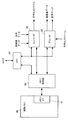
図25は、一例として、動画像のエンコードとデコードを並行して実行することが可能な画像処理装置の要部構成を示す図である。
図25に示す画像処理装置は、例えば、動画像データおよび音声データの入力を受けてこれらをMPEGなどの圧縮符号化方式でエンコードし、各種の記録媒体に記録する機能と、記録媒体の記録データをデコードし、動画像および音声を再生出力する機能とを具備する画像記録再生装置や撮像装置などに設けられる。この画像処理装置では、動画像および音声のエンコードとデコードとを並行して実行することが可能となっており、これらの処理が、OS(Operating System)を搭載しない、いわゆる組み込み型システムにより実行されるようになっている。
FIG. 25 is a diagram illustrating a main configuration of an image processing apparatus capable of executing encoding and decoding of a moving image in parallel as an example.
The image processing apparatus shown in FIG. 25 receives, for example, moving image data and audio data, encodes them with a compression encoding method such as MPEG, and records them on various recording media, and the recording data of the recording media Is provided in an image recording / reproducing apparatus, an imaging apparatus, or the like having a function of decoding and decoding moving images and sounds. In this image processing apparatus, it is possible to execute encoding and decoding of moving images and sounds in parallel, and these processes are executed by a so-called embedded system that does not include an OS (Operating System). It has become so.
この画像処理装置は、図25に示すように、エンコード/デコードの制御のためのCPU11、エンコーダ21、デコーダ31、および処理中の画像データの一時保存のためにエンコーダ21およびデコーダ31により共用される画像メモリ40を具備している。
As shown in FIG. 25, this image processing apparatus is shared by the
CPU11は、外部のホストコントローラと通信し、このホストコントローラからの情報に応じてエンコーダ21およびデコーダ31の処理を制御する。具体的には、ホストコントローラから、エンコード/デコードの命令、生成する画像のサイズ、確保すべきメモリ領域の数などの情報を受け取って、対応するエンコーダ21またはデコーダ31にこれらの情報を出力し、処理を開始させる。
The
エンコーダ21は、入力された動画像および音声のデジタルデータに対して、MPEG方式などの所定の圧縮符号化方式に従って圧縮符号化処理を施し、動画像および音声の符号化ストリームを生成する処理を実行する。また、デコーダ31は、入力された動画像および音声の符号化ストリームに対して伸張復号化処理を施す。エンコーダ21およびデコーダ31は、動画像データのエンコード、デコードをそれぞれ実行する際に、画像メモリ40にアクセスして、処理中の画像データを画像メモリ40に一時的に格納する。
The
画像メモリ40は、例えばSDRAM(Synchronous Dynamic Random Access Memory)などの半導体メモリからなり、その内部に、外部からのアクセスを受けるメモリI/F41を具備している。メモリI/F41は、エンコーダ21およびデコーダ31から供給された画像データを、画像メモリ40の指定された領域に格納する。また、エンコーダ21およびデコーダ31から指定された読み出しアドレスに応じて、画像メモリ40から画像データを読み出して出力する。
The
このような画像処理装置において、動画像のエンコードが行われる場合は、CPU11は、ホストコントローラからの情報に基づいて、エンコーダ21に対してエンコードの開始を命令するとともに、画像サイズや、確保すべきメモリ領域に対応する画像の枚数を指定する。エンコーダ21は、動画像データの入力を受けると、CPU11からの情報に従って、画像メモリ40に対して画像を格納するメモリ領域を確保し、対応する物理アドレスをメモリI/F41に指定して、処理中の画像データをそのメモリ領域に順次格納しながらエンコードを実行する。
In such an image processing apparatus, when encoding a moving image, the
また、動画像のデコードが行われる場合は、同様に、CPU11からデコーダ31に対して画像サイズや画像の枚数がデコーダ31に対して指定され、符号化ストリームの入力を受けたデコーダ31は、CPU11により指定された枚数に対応するメモリ領域を画像メモリ40に確保し、対応する物理アドレスをメモリI/F41に指定して、処理中の画像データをそのメモリ領域に順次格納しながらデコードを実行する。
When a moving image is decoded, similarly, the
また、音声のエンコードおよびデコードが行われる際には、エンコーダ21およびデコーダ31は、ホストコントローラからCPU11を通じて供給される情報に従って、入力される音声データや符号化ストリームを順次処理していく。この際に、処理中の音声データを画像メモリ40に一時的に格納するようにしてもよい。
Further, when audio encoding and decoding are performed, the
なお、1系統のデータの符号化処理と、他の1系統のデータの復号処理とを並行して実行することが可能な従来の装置として、以下のような画像の復号装置があった。この復号装置では、データの符号化および復号が共用して行われる逆変換回路が設けられている。そして、高能率符号化された画像信号として入力されて可変長復号回路および逆量子化回路を経由した信号と、入力された別系統の画像信号とが、多重化回路により選択されて逆変換回路に入力され、前者の信号は逆変換回路において復号されて出力され、後者の画像信号は、逆変換回路において符号化された後、さらに量子化回路および可変長符号化回路を介して出力される。ここで、逆変換回路を実時間速度の2倍またはそれ以上の速度で動作させることにより、逆変換回路における復号機能と符号化機能とを切り替えて使用し、復号処理と符号化処理とを並行して実行することが可能となる(例えば、特許文献1参照)。
ところで、複数の記録媒体を具備する画像記録再生装置では、各記録媒体を用いた動画像データの記録または再生を行っている途中で、エンコーダまたはデコーダの処理対象となる画像サイズを変更可能とする要求がある。例えば、磁気テープとメモリカードとを具備するデジタルビデオカメラにおいて、撮像画像を各記録媒体に記録している途中で、メモリカードへの記録動作のみを中断し、記録画像の画像サイズを変更して記録動作を再開させる場合などが想定される。 By the way, in an image recording / reproducing apparatus having a plurality of recording media, it is possible to change the image size to be processed by the encoder or decoder while recording or reproducing moving image data using each recording medium. There is a request. For example, in a digital video camera equipped with a magnetic tape and a memory card, only the recording operation to the memory card is interrupted while the captured image is being recorded on each recording medium, and the image size of the recorded image is changed. It is assumed that the recording operation is resumed.
しかし、図25に示した従来の画像処理装置では、エンコーダ21およびデコーダ31により画像メモリ40に確保されるメモリ領域の大きさや数は、ホストコントローラからCPU11を介して指定される、処理対象とする画像サイズに応じて、あらかじめ決められている。このため、一旦エンコードおよびデコードが開始されると、画像メモリ40内にメモリ領域が固定的に確保され、すべてのエンコードおよびデコードの動作を停止させない限り、画像サイズの設定を変更することができなかった。また、エンコーダ21やデコーダ31は、確保したメモリ領域を、その物理アドレスを常に認識して管理する必要があるため、画像サイズなどを変更した際にメモリ領域の管理が煩雑となり、画像サイズの変更に対して柔軟に対応できないことが問題であった。
However, in the conventional image processing apparatus shown in FIG. 25, the size and number of memory areas secured in the
本発明はこのような点に鑑みてなされたものであり、1つの画像メモリを共用してエンコードおよびデコードを並行して実行する場合に、処理対象の画像サイズの変更に対して柔軟に対応することが可能なメモリ管理方法を提供することを目的とする。 The present invention has been made in view of such a point, and flexibly copes with a change in the image size to be processed when encoding and decoding are performed in parallel by sharing one image memory. It is an object of the present invention to provide a memory management method that can be used.
また、本発明の他の目的は、1つの画像メモリを共用してエンコードおよびデコードを並行して実行する場合に、処理対象の画像サイズの変更に対して柔軟に対応することが可能な画像処理装置を提供することである。 Another object of the present invention is to perform image processing that can flexibly cope with a change in the image size to be processed when one image memory is shared and encoding and decoding are executed in parallel. Is to provide a device.
さらに、本発明の他の目的は、1つの画像メモリを共用してエンコードおよびデコードを並行して実行する場合に、処理対象の画像サイズの変更に対して柔軟に対応することが可能なメモリ管理プログラムを提供することである。 Furthermore, another object of the present invention is to provide a memory management that can flexibly cope with a change in the image size to be processed when one image memory is shared and encoding and decoding are executed in parallel. Is to provide a program.
本発明では上記課題を解決するために、複数の画像処理手段により1つの画像メモリを作業領域として共用して、前記各画像処理手段による処理を並行して実行するためのメモリ管理方法において、メモリ領域確保手段が、複数の前記画像処理手段のそれぞれの処理のために個別に指定される画像サイズおよび画像枚数の入力を受けて、前記画像サイズに対応するメモリ領域を前記画像メモリ上の空き領域に前記画像枚数分だけ個別に割り当てて確保し、確保した前記メモリ領域を示すアドレスを出力するメモリ領域確保ステップと、メモリ領域管理手段が、前記メモリ領域確保ステップで確保された前記各メモリ領域の識別情報と、少なくとも前記アドレスを含む、前記メモリ領域にアクセスするためのアクセス情報との対応関係を、前記メモリ領域ごとに記憶したメモリ領域情報を生成するメモリ領域情報生成ステップと、前記メモリ領域管理手段が、前記各メモリ領域に対する前記各画像処理手段からの使用要求および返却要求を受け付けて、前記各メモリ領域の使用状態を前記メモリ領域情報を用いて管理するメモリ領域管理ステップとを含むことを特徴とするメモリ管理方法が提供される。 In the present invention, in order to solve the above problems, in a memory management method for sharing a single image memory as a work area by a plurality of image processing means and executing the processes by the image processing means in parallel, The area securing means receives an input of the image size and the number of images individually designated for each processing of the plurality of image processing means, and sets a memory area corresponding to the image size as a free area on the image memory. A memory area securing step for individually assigning and securing the number of images corresponding to the number of images, and outputting an address indicating the secured memory area, and a memory area management means for each memory area secured in the memory area securing step The correspondence relationship between the identification information and the access information for accessing the memory area including at least the address, A memory area information generating step for generating memory area information stored for each memory area; and the memory area management means receives a use request and a return request from the image processing means for each memory area, and And a memory area management step for managing a use state of the area by using the memory area information.
このようなメモリ管理方法では、メモリ領域確保手段によるメモリ領域確保ステップにおいて、指定された画像サイズに対応するメモリ領域が、指定された画像枚数分だけ画像メモリ上の空き領域内に個別に確保されるので、各メモリ領域は、画像メモリ上に画像枚数分だけ固定的に割り当てられず、それぞれが個別に分散して割り当てられる。また、メモリ領域管理手段によるメモリ領域情報生成ステップにおいて、確保された各メモリ領域の識別情報と、メモリ領域にアクセスするためのアクセス情報との対応関係をメモリ領域ごとに記憶したメモリ領域情報を生成する。これにより、メモリ領域情報を識別する番号などを各画像処理手段が指定することで、対応するメモリ領域にアクセスし、画像データの書き込みおよび読み出しを行うことが可能となる。さらに、メモリ領域管理手段によるメモリ領域管理ステップにおいて、各メモリ領域に対する各画像処理手段からの使用要求および返却要求を受け付けて、各メモリ領域の使用状態をメモリ領域情報を用いて管理することにより、各画像処理手段は、メモリ領域を使用する際に、対応する画像メモリ内のアドレスなどを認識して使用状態を管理する必要がなくなる。 In such a memory management method, in the memory area securing step by the memory area securing unit, the memory area corresponding to the designated image size is individually secured in the free area on the image memory for the designated number of images. Therefore, each memory area is not fixedly allocated by the number of images on the image memory, but is individually distributed and allocated. Also, in the memory area information generation step by the memory area management means, memory area information is generated in which the correspondence between the identification information of each secured memory area and the access information for accessing the memory area is stored for each memory area. To do. Thus, each image processing means designates a number for identifying the memory area information and the like, thereby making it possible to access the corresponding memory area and write and read the image data. Furthermore, in the memory area management step by the memory area management means, by accepting a use request and a return request from each image processing means for each memory area, and managing the use state of each memory area using the memory area information, Each image processing unit does not need to recognize the address in the corresponding image memory and manage the use state when using the memory area.
また、本発明では、複数の画像処理手段により1つの画像メモリを作業領域として共用して、前記各画像処理手段による処理を並行して実行することが可能な画像処理装置において、複数の前記画像処理手段のそれぞれの処理のために個別に指定される画像サイズおよび画像枚数の入力を受けて、前記画像サイズに対応するメモリ領域を前記画像メモリ上の空き領域に前記画像枚数分だけ個別に割り当てて確保し、確保した前記メモリ領域を示すアドレスを出力するメモリ領域確保手段と、前記メモリ領域確保手段により確保された前記各メモリ領域の識別情報と、少なくとも前記アドレスを含む、前記メモリ領域にアクセスするためのアクセス情報との対応関係を、前記メモリ領域ごとに記憶したメモリ領域情報を保持するとともに、前記各メモリ領域に対する前記各画像処理手段からの使用要求および返却要求を受け付けて、前記各メモリ領域の使用状態を前記メモリ領域情報を用いて管理するメモリ領域管理手段とを有することを特徴とする画像処理装置が提供される。 According to the present invention, in an image processing apparatus in which one image memory is shared as a work area by a plurality of image processing means, and the processing by each of the image processing means can be executed in parallel, a plurality of the images In response to the input of the image size and the number of images individually specified for each processing of the processing means, the memory area corresponding to the image size is individually allocated to the empty area in the image memory by the number of images. Memory area securing means for outputting an address indicating the secured memory area, identification information of each memory area secured by the memory area securing means, and accessing the memory area including at least the address The memory area information stored for each memory area, the correspondence relationship with the access information for Image processing, comprising: memory area management means for receiving use requests and return requests from the respective image processing means for the memory area, and managing the use state of each of the memory areas using the memory area information. An apparatus is provided.
ここで、メモリ領域確保手段は、指定された画像サイズに対応するメモリ領域を、指定された画像枚数分だけ画像メモリ上の空き領域内に個別に確保するので、各メモリ領域は、画像メモリ上に画像枚数分だけ固定的に割り当てられず、それぞれが個別に分散して割り当てられる。また、メモリ領域管理手段は、確保された各メモリ領域の識別情報と、メモリ領域にアクセスするためのアクセス情報との対応関係をメモリ領域ごとに記憶したメモリ領域情報を生成する。これにより、メモリ領域情報を識別する番号などを各画像処理手段が指定することで、対応するメモリ領域にアクセスし、画像データの書き込みおよび読み出しを行うことが可能となる。さらに、各メモリ領域に対する各画像処理手段からの使用要求および返却要求を受け付けて、各メモリ領域の使用状態をメモリ領域情報を用いて管理することにより、各画像処理手段は、メモリ領域を使用する際に、対応する画像メモリ内のアドレスなどを認識して使用状態を管理する必要がなくなる。 Here, the memory area securing means individually secures the memory area corresponding to the designated image size in the free area on the image memory for the designated number of images, so that each memory area is stored on the image memory. Are not fixedly allocated to the number of images, but are individually distributed and allocated. In addition, the memory area management unit generates memory area information in which a correspondence relationship between the identification information of each secured memory area and the access information for accessing the memory area is stored for each memory area. Thus, each image processing means designates a number for identifying the memory area information and the like, thereby making it possible to access the corresponding memory area and write and read the image data. Furthermore, each image processing unit uses the memory area by receiving a use request and a return request from each image processing unit for each memory area and managing the use state of each memory area using the memory area information. At this time, it is not necessary to manage the usage state by recognizing the address in the corresponding image memory.
本発明によれば、複数の画像処理手段のそれぞれが、画像メモリ内のメモリ領域のアドレスなどを認識して使用状態を管理することなく、単にメモリ領域情報を指定することで、対応するメモリ領域にアクセスし、画像データの書き込みおよび読み出しを行うことが可能となる。また、画像サイズに対応するメモリ領域が画像メモリ内に個別に割り当てられるので、画像サイズを変更した場合にも、割り当てた領域を一旦解放して空き領域に設定し、その空き領域を異なる画像サイズに対応するメモリ領域として容易に再利用することが可能となる。従って、各画像処理手段の処理負担を高めることなく、ある画像処理手段において画像サイズが変更された場合にも、他の画像処理手段の処理を中断せずに、必要なメモリ領域を確保し直して利用させることが可能となる。 According to the present invention, each of the plurality of image processing means recognizes the address of the memory area in the image memory and manages the usage state without specifying the memory area information. It is possible to write and read image data. Also, since the memory area corresponding to the image size is individually allocated in the image memory, even if the image size is changed, the allocated area is once released and set as a free area, and the free area is set to a different image size. Can be easily reused as a memory area corresponding to. Therefore, even if the image size is changed in one image processing unit without increasing the processing load on each image processing unit, the necessary memory area is re-secured without interrupting the processing of other image processing units. Can be used.
以下、本発明の実施の形態を図面を参照して詳細に説明する。
[第1の実施の形態の構成]
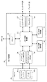
以下の第1の実施の形態では、動画像および音声の信号を、所定の圧縮符号化方式に従ってエンコード/デコードする画像処理装置に、本発明を適用した場合を想定する。図1は、本発明の第1の実施の形態に係る画像処理装置の要部構成を示すブロック図である。
Hereinafter, embodiments of the present invention will be described in detail with reference to the drawings.
[Configuration of First Embodiment]
In the following first embodiment, it is assumed that the present invention is applied to an image processing apparatus that encodes / decodes moving image and audio signals according to a predetermined compression encoding method. FIG. 1 is a block diagram showing a main configuration of the image processing apparatus according to the first embodiment of the present invention.
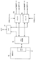
図1に示す画像処理装置は、例えば、動画像データおよび音声データの入力を受けてこれらをMPEGなどの圧縮符号化方式でエンコードし、各種の記録媒体に記録する機能と、記録媒体の記録データをデコードし、動画像および音声を再生出力する機能とを具備する画像記録再生装置や撮像装置などに設けられる。この画像処理装置では、動画像および音声のエンコードとデコードとを並行して実行することが可能となっており、これらの処理が、OSを搭載しない、いわゆる組み込み型システムにより実行されるようになっている。 The image processing apparatus shown in FIG. 1 receives, for example, moving image data and audio data, encodes them by a compression encoding method such as MPEG, and records them on various recording media, and the recording data of the recording media Is provided in an image recording / reproducing apparatus, an imaging apparatus, or the like having a function of decoding and decoding moving images and sounds. In this image processing apparatus, it is possible to execute encoding and decoding of moving images and sounds in parallel, and these processes are executed by a so-called embedded system that does not include an OS. ing.
この画像処理装置は、図1に示すように、エンコード/デコードの制御のためのCPU10、エンコーダ20、デコーダ30、処理中の画像データの一時保存のためにエンコーダ20およびデコーダ30により共用される画像メモリ40、および画像メモリ40の書き込み/読み出しを制御するメモリ制御部50を具備している。
As shown in FIG. 1, the image processing apparatus includes a
CPU10は、外部のホストコントローラと通信し、このホストコントローラからの情報に応じて、エンコーダ20、デコーダ30およびメモリ制御部50の動作を制御する。具体的には、例えば、ホストコントローラに指示された画像サイズや、確保すべきメモリ領域の数をメモリ制御部50に通知するとともに、この画像サイズでのエンコード/デコードの実行をエンコーダ20およびデコーダ30に指示する。また、エンコーダ20およびデコーダ30からの画像メモリ40に対する書き込み/読み出し要求をメモリ制御部50に通知し、画像データが書き込まれたメモリ領域を示す識別IDを、エンコーダ20およびデコーダ30とメモリ制御部50との間で転送する。
The
エンコーダ20は、入力された動画像および音声のデジタルデータに対して、MPEG方式などの所定の圧縮符号化方式に従って圧縮符号化処理を施し、動画像および音声の符号化ストリームを生成する。また、デコーダ30は、入力された動画像および音声の符号化ストリームに対して伸張復号化処理を施す。エンコーダ20およびデコーダ30は、動画像のエンコード、デコードをそれぞれ実行する際に、メモリ制御部50を通じて画像メモリ40にアクセスし、処理中の画像データを画像メモリ40に一時的に格納する。
The
画像メモリ40は、例えばSDRAMなどの半導体メモリからなり、その内部に、外部からのアクセスを受け付けるメモリI/F41を具備している。メモリI/F41は、画像メモリ40のハードウェアI/Fをメモリ制御部50に対して提供し、メモリ制御部50からアドレスおよび画像サイズの設定を受けて、エンコーダ20およびデコーダ30からメモリ制御部50を通じて供給された画像データを、画像メモリ40内の対応する領域に格納する。また、メモリ制御部50から指定された領域の画像データを読み出して、メモリ制御部50を通じてエンコーダ20およびデコーダ30に出力する。なお、メモリI/F41は、後述するように、ルックアップテーブルおよびデータフォーマットを用いて、画像メモリ40へのデータの書き込み/読み出しを制御する。
The
メモリ制御部50は、エンコーダ20およびデコーダ30からの画像メモリ40に対するアクセスを一元的に管理する機能ブロックである。メモリ制御部50は、エンコードやデコードが実行される際に、画像サイズや確保すべきメモリ領域の数の情報をCPU10から受け取り、これらの情報に基づいて画像メモリ40内のメモリ領域を確保する。そして、エンコーダ20およびデコーダ30から供給された画像メモリ40に格納し、その格納領域を示す識別IDを、CPU10を通じてエンコーダ20およびデコーダ30に通知する。また、エンコーダ20およびデコーダ30からCPU10を通じて識別IDが指定されると、識別IDに応じた画像メモリ40上のメモリ領域から画像データを読み出し、エンコーダ20およびデコーダ30に出力する。
The
このような画像処理装置において、動画像のエンコードが行われる場合は、CPU10は、ホストコントローラからの情報に基づいて、エンコーダ20に対してエンコードの開始を命令するとともに、画像サイズや、確保すべきメモリ領域に対応する画像の枚数をメモリ制御部50に指定する。メモリ制御部50は、CPU10からの情報に応じて、エンコードに必要なメモリ領域を画像メモリ40に確保する。
In such an image processing apparatus, when encoding a moving image, the
エンコーダ20は、動画像データの入力を受けると、処理中の画像データをメモリ制御部50を通じて画像メモリ40に一時的に格納し、また適宜読み出しながらエンコードを行う。画像データを格納する際には、エンコーダ20からの要求がCPU10を通じてメモリ制御部50に伝達され、メモリ制御部50は、確保したメモリ領域のうちの1つにエンコーダ20からの画像データを書き込み、当該メモリ領域を示す識別IDを、CPU10を通じてエンコーダ20に通知する。
When receiving the input of moving image data, the
その後、画像メモリ40から画像データを読み出す際には、エンコーダ20は、読み出す画像データに対応する識別IDを、CPU10を通じてメモリ制御部50に通知する。メモリ制御部50は、識別IDに対応する画像メモリ40内のメモリ領域から画像データを読み出し、エンコーダ20に出力する。そして、ホストコントローラからエンコードの終了が要求されると、メモリ制御部50は、エンコードのために確保していたメモリ領域を解放し、他のデータの書き込みが可能な状態に設定する。
Thereafter, when reading the image data from the
動画像のデコードが行われる場合も、上記と同様の動作が行われる。すなわち、デコードが開始されると、メモリ制御部50により必要なメモリ領域が確保される。そして、デコーダ30からの画像データがメモリ制御部50の制御により1つのメモリ領域に格納され、そのメモリ領域の識別IDがデコーダ30に通知される。画像データの読み出しの際は、デコーダ30から識別IDがメモリ制御部50に通知され、メモリ制御部50は、その識別IDに対応するメモリ領域から画像データを読み出し、デコーダ30に出力する。
When moving image decoding is performed, the same operation as described above is performed. That is, when decoding is started, the
このように、上記の画像処理装置では、エンコーダ20およびデコーダ30が、画像メモリ40に対してメモリ制御部50を介して間接的にアクセスする構成となっている。エンコーダ20およびデコーダ30は、画像メモリ40の物理アドレスの代わりに、メモリ制御部50により確保されるメモリ領域の識別IDを用いて、画像データの書き込み/読み出しを要求することができる。
As described above, the image processing apparatus is configured such that the
一方、メモリ制御部50は、エンコーダ20およびデコーダ30の一方の処理が開始されるたびに、その処理のために必要な画像メモリ40内のメモリ領域をその都度確保する。このとき、メモリ制御部50は、画像メモリ40内の単位メモリ領域をノードとした二分木構造を用いて、画像メモリ40内の空き領域にメモリ領域を効率的に割り当て、また、画像メモリ40のハードウェアI/Fに合わせて、割り当てたメモリ領域をメモリI/F41に設定する。
On the other hand, each time one of the processes of the
このため、エンコード/デコードの少なくとも一方の処理対象となる画像サイズがホストコントローラからの指示により変更された場合にも、変更された処理のために確保していたメモリ領域を一旦解放して空き領域に設定し、その空き領域を変更後の画像サイズに対応するメモリ領域として容易に再利用することが可能となる。これとともに、画像サイズに応じたメモリ領域の確保がメモリ制御部50に応じて一元的に制御され、エンコーダ20およびデコーダ30は、画像メモリ40の仕様や物理アドレスを常に認識することなく、処理中の画像データの受け渡しを行うことが可能となる。
For this reason, even when the image size to be processed by at least one of encoding / decoding is changed by an instruction from the host controller, the memory area reserved for the changed processing is once released to free space Therefore, the empty area can be easily reused as a memory area corresponding to the changed image size. At the same time, the securing of the memory area according to the image size is centrally controlled according to the
ここで、エンコード/デコードの処理対象となる画像サイズが変更される場合とは、エンコーダ20およびデコーダ30による処理中に画像メモリ40に一時的に格納される画像データの画像サイズに変更が生じる場合を意味する。例えば、エンコード時には、入力された動画像データに対してエンコーダ20が画像サイズを変化させた後、エンコードを実行する、あるいは、画像サイズの変更された動画像データの入力を受けてエンコードを実行することにより、生成される符号化ストリームの画像サイズが変更される場合などが該当する。また、デコード時には、デコーダ30に入力される符号化ストリームの画像サイズが変更される場合などが該当する。
Here, the case where the image size to be encoded / decoded is changed means that the image size of the image data temporarily stored in the
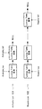
次に、図2は、メモリ制御部50の内部構成を示すブロック図である。
図2に示すように、メモリ制御部50は、メモリ領域管理部51、メモリ確保処理部52、メモリ解放処理部53、ルックアップテーブル設定部54、データフォーマット設定部55、CPU・I/F56、エンコーダI/F57およびデコーダI/F58を具備している。なお、図2では、画像メモリ40のメモリI/F41の具備するルックアップテーブル41aおよびデータフォーマット41bも示している。
Next, FIG. 2 is a block diagram showing an internal configuration of the
As shown in FIG. 2, the
メモリ領域管理部51は、CPU・I/F56を通じてCPU10と通信し、メモリ制御部50内の全体の動作を制御する。具体的には、CPU10から指定された画像サイズおよび枚数に対応するメモリ領域の確保を、メモリ確保処理部52、ルックアップテーブル設定部54およびデータフォーマット設定部55に要求し、確保されたメモリ領域を識別IDを用いてエンコーダ20およびデコーダ30に提供して、その使用状態を管理する。また、エンコーダ20およびデコーダ30と画像メモリ40との間のデータ転送を制御する。そして、エンコード/デコードの処理が終了したときに、メモリ解放処理部53、ルックアップテーブル設定部54およびデータフォーマット設定部55を制御して、確保していたメモリ領域を解放させる。
The memory
メモリ確保処理部52は、メモリ領域管理部51から指定された画像サイズに対応するメモリ領域を画像メモリ40内の空き領域に割り当て、その領域のアドレスを算出する。具体的には、メモリ確保処理部52は、画像メモリ40内の単位メモリ領域をノードとした二分木構造を用いて、各単位メモリ領域の割り当て状態を管理する。そして、メモリ領域管理部51に指定された画像サイズのデータを格納可能なメモリ領域を空き領域から抽出し、その領域の先頭アドレスをメモリ領域管理部51に対して出力する。メモリ解放処理部53は、メモリ領域管理部51から指定されたメモリ領域を解放する処理を行う。
The memory
ルックアップテーブル設定部54およびデータフォーマット設定部55は、確保されたメモリ領域が使用可能となるように、画像メモリ40のアクセス仕様に合わせて情報の設定を行う機能ブロックである。本実施の形態では、メモリ領域の先頭アドレスと、そのメモリ領域のデータサイズを1次元または2次元のデータとして表した画像サイズとを指定することで、画像メモリ40の書き込み/読み出しを行うことが可能となっている。そのために、メモリI/F41は、メモリ領域の大きさに対応する画像サイズの設定を保持するルックアップテーブル41aと、メモリ領域の先頭アドレスとこれに対応するルックアップテーブル41a内の要素とが対応付けられたデータフォーマット41bを具備している。
The look-up
ルックアップテーブル設定部54は、メモリ領域を確保する際に、メモリ領域管理部51から指定された画像サイズを、メモリI/F41のルックアップテーブル41aに対して設定する。
The look-up
データフォーマット設定部55は、メモリ確保処理部52により算出されたアドレスを、メモリI/F41のデータフォーマット41bに対して設定するとともに、そのアドレスをルックアップテーブル41aに対応付ける。そして、画像メモリ40に対する画像データの書き込み/読み出し時に、メモリ領域管理部51から指定される情報に応じて、データフォーマット41b内の対応する要素を指定し、書き込み/読み出しをメモリI/F41に対して要求する。
The data
CPU・I/F56は、CPU10とメモリ領域管理部51との間で情報を受け渡すためのI/F回路である。また、エンコーダI/F57およびデコーダI/F58は、それぞれエンコーダ20およびデコーダ30とメモリ領域管理部51との間で画像データを受け渡すためのI/F回路である。
The CPU / I /
[メモリ領域管理部の動作]
次に、メモリ制御部50内の各部の動作について詳述する。まず、メモリ領域管理部51によるメモリ領域の管理方法について説明する。
[Operation of memory area manager]
Next, the operation of each unit in the
図3は、確保したメモリ領域のメモリ領域管理部51による管理方法を説明するための図である。
メモリ領域管理部51は、図3に示すように、画像サイズ要素および画像メモリ要素という2つの要素がポインタにより接続された線形リストを用いて、メモリ領域を管理する。
FIG. 3 is a diagram for explaining a management method by the memory
As shown in FIG. 3, the memory
画像サイズ要素は、1つのエンコーダ20またはデコーダ30による処理の実行に対応して生成される要素であり、後に生成された他の画像サイズ要素をポインタにより指し示すことで構成されるリスト構造を有している。1つの画像サイズ要素は、エンコードまたはデコードの処理の開始時に、CPU10に指定された画像サイズを設定した画像メモリ要素を、このときCPU10に指定された枚数分だけ具備する。すなわち、各画像メモリ要素は、エンコーダ20またはデコーダ30が画像メモリ40に格納する1ピクチャ分の画像データのために確保されるメモリ領域に対応している。
The image size element is an element generated corresponding to the execution of processing by one
また、1つの画像サイズ要素において、画像データが格納済みである画像メモリ要素と未格納である画像メモリ要素とが、ポインタを用いたリスト構造を持つアクティベートリスト(Activate List)およびネゲートリスト(Negate List)にそれぞれ接続される。そして、エンコーダ20から画像メモリ40に対する1ピクチャ分の画像データの書き込みが要求されると、ネゲートリストの先頭の画像メモリ要素が、アクティベートリストの最後尾に接続され、画像メモリ40に書き込んだ1ピクチャ分の画像データが不要となると、当該画像メモリ要素がネゲートリストの最後尾に接続される。
Also, in one image size element, an image memory element in which image data has been stored and an image memory element in which image data has not been stored include an activate list and a negate list (Negate List) having a list structure using pointers. ) Respectively. When the
また、画像サイズ要素は、アクティベートリストの先頭および最後尾の画像メモリ要素をそれぞれ示すアクティベートトップ(Activate_top)およびアクティベートテール(Activate_tail)と、ネゲートリストの先頭および最後尾の画像メモリ要素をそれぞれ示すネゲートトップ(Negate_top)およびネゲートテール(Negate_tail)とを常に認識することで、各リストを管理している。 In addition, the image size element includes an activate top (Activate_top) and an activate tail (Activate_tail) that indicate the first and last image memory elements of the activate list, respectively, and a negate top that indicates the first and last image memory elements of the negate list, respectively. Each list is managed by always recognizing (Negate_top) and negate tail (Negate_tail).
図3の例では、2つの画像サイズ要素101aおよび101bが生成されている。本実施の形態では、エンコーダ20およびデコーダ30がそれぞれ1つずつ設けられていることから、画像サイズ要素は最大2つ生成される。
In the example of FIG. 3, two
例えば、エンコードのために画像サイズ要素101aが生成されたものとすると、エンコーダ20による処理のために5つの画像メモリ要素102a〜102c,103aおよび103bに対応するメモリ領域が確保され、それらのうち、アクティベートリスト102に接続された画像メモリ要素102a〜102cに対応するメモリ領域にはすでにエンコーダ20からの画像データが格納され、ネゲートリスト103に接続された画像メモリ要素103aおよび103bに対応するメモリ領域は使用されていない状態となっている。
For example, assuming that an
また、同様に、デコードのために画像サイズ要素101bが生成されたものとすると、デコーダ30による処理のために4つの画像メモリ要素105a〜105dに対応するメモリ領域が確保されており、アクティベートリスト104には要素が存在しておらず、ネゲートリスト105に接続されたすべての画像メモリ要素105a〜105dに対応するメモリ領域が未使用状態となっている。
Similarly, assuming that the
この図3の状態から、例えばデコーダ30によるデコードが終了されると、画像サイズ要素101bとこれが具備するすべての画像メモリ要素105a〜105dが消去される。これにより、デコーダ30の処理のために確保されていたメモリ領域が解放される。また、図3の状態から、例えばデコーダ30の処理対象の画像サイズをデコードの途中で変更する場合には、一旦画像サイズ要素101bを消去した後、新たな画像サイズが設定された画像メモリ要素を具備する画像サイズ要素を生成する。このような設定変更の間、エンコーダ20は、画像サイズ要素101aの具備する画像メモリ要素に対応するメモリ領域を用いてエンコードを続行することができる。
When the decoding by the
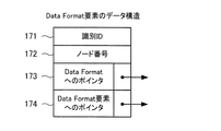
図4は、画像サイズ要素および画像メモリ要素のデータ構造を示す図である。
各画像サイズ要素には、メモリ領域管理部51により図4(A)に示すようなデータが設定される。識別ID111は、各画像サイズ要素を識別するユニークな番号である。画像幅112および画像高さ113は、当該画像サイズ要素が具備する画像メモリ要素に設定される画像サイズを示し、画像枚数114は、その画像メモリ要素の数を示す。
FIG. 4 is a diagram showing the data structure of the image size element and the image memory element.
For each image size element, data as shown in FIG. 4A is set by the memory
また、当該画像サイズの具備する画像メモリ要素を管理するために、当該画像サイズ要素内のアクティベートトップ、アクティベートテール、ネゲートトップおよびネゲートテールとなっている画像メモリ要素を指し示すポインタ115〜118が設定される。これらのポインタ115〜118としては、例えば後述する画像メモリ要素の識別IDなどが用いられる。さらに、当該画像サイズ要素より後に生成された他の画像サイズ要素へのポインタ119が、例えばその画像サイズ要素の識別IDにより設定される。
Also, in order to manage the image memory elements included in the image size,
一方、各画像メモリ要素には、メモリ領域管理部51により図4(B)に示すようなデータが設定される。識別ID121は、各画像メモリ要素を識別するユニークな番号であり、対応するメモリ領域に画像データを格納した際にエンコーダ20またはデコーダ30に提供されるものである。ノード番号122は、メモリ確保処理部52により確保されたメモリ領域に対応する番号である。
On the other hand, data as shown in FIG. 4B is set in each image memory element by the memory
また、画像メモリ40上に確保される実際のメモリ領域と対応付けるために、ルックアップテーブル設定部54が保持するルックアップテーブル要素へのポインタ123と、データフォーマット設定部55が保持するデータフォーマット要素へのポインタ124が設定される。これらのポインタ123および124としては、例えばその要素の識別IDが用いられる。なお、ルックアップテーブル要素およびデータフォーマット要素については後述する。
Further, in order to associate with an actual memory area secured on the
さらに、同じアクティベートリストまたはネゲートリストにおいて次に接続された画像メモリ要素を指し示すポインタ125が、例えばその画像メモリ要素の識別IDにより設定される。
Further, a
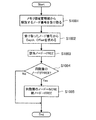
次に、メモリ領域管理部51の処理について説明する。まず、図5は、メモリ領域を確保する際のメモリ領域管理部51の処理の流れを示すフローチャートである。
〔ステップS101〕ホストコントローラよりエンコードまたはデコードの開始がCPU10に対して要求されたとき、CPU10は、ホストコントローラから指定された確保すべき画像サイズ、および必要なメモリ領域に対応する画像の枚数を、CPU・I/F56を介してメモリ領域管理部51に通知する。メモリ領域管理部51は、CPU10からの画像サイズおよび枚数を受け取り、以下の処理の実行を開始する。
Next, processing of the memory
[Step S101] When the host controller requests the
〔ステップS102〕画像サイズ要素のリストに、新たな画像サイズ要素を加える。このとき、新たな画像サイズ要素の識別ID111の欄に値を設定し、また、すでに生成されていた画像サイズ要素がある場合には、その要素のポインタ119の欄に、新たな画像サイズ要素の識別IDを格納する。
[Step S102] A new image size element is added to the list of image size elements. At this time, a value is set in the
〔ステップS103〕新たな画像サイズ要素について、CPU10からの画像サイズを画像幅112および画像高さ113の欄に格納し、枚数を画像枚数114の欄に格納する。なお、画像サイズが1次元のデータとして表されている場合は、そのデータは例えば画像幅112の欄にのみ格納されればよい。
[Step S103] For the new image size element, the image size from the
〔ステップS104〕新たに生成した画像サイズ要素のネゲートリストの最後尾に、画像メモリ要素を1つ加える。このとき、画像サイズ要素のネゲートテールを示すポインタ118を更新する。また、すでにネゲートリストに画像サイズ要素が存在する場合には、ネゲートトップを示すポインタ117を更新するとともに、最後尾の画像サイズ要素に設定されたポインタ119に、新たな画像サイズ要素の識別IDを設定する。
[Step S104] One image memory element is added to the end of the newly generated image size element negate list. At this time, the
〔ステップS105〕ステップS101で受け取った画像サイズをメモリ確保処理部52に渡し、その画像サイズに対応するメモリ領域の確保を要求する。これにより、メモリ確保処理部52は、図21で説明するように、受け取った画像サイズに対応するメモリ領域を画像メモリ40内に確保し、そのメモリ領域を示す二分木構造のノード番号と、メモリ領域の先頭アドレスとをメモリ領域管理部51に返す。
[Step S105] The image size received in step S101 is transferred to the memory securing
〔ステップS106〕メモリ確保処理部52から先頭アドレスおよびノード番号を受け取る。
〔ステップS107〕当該画像メモリ要素のノード番号122の欄に、メモリ確保処理部52から受け取ったノード番号を格納する。
[Step S106] The head address and the node number are received from the memory
[Step S107] The node number received from the memory
〔ステップS108〕ルックアップテーブル設定部54に対して、CPU10から指定された画像サイズを渡す。これにより、ルックアップテーブル設定部54は、図12で説明するように、画像サイズをルックアップテーブル41aに設定し、また、対応するルックアップテーブル要素を更新して、その要素の識別IDをメモリ領域管理部51に返す。
[Step S108] The image size designated by the
〔ステップS109〕ルックアップテーブル設定部54からの識別IDを受け取り、ルックアップテーブル要素へのポインタ123としてその識別IDを設定する。
〔ステップS110〕メモリ確保処理部52から受け取った先頭アドレスおよびノード番号、ルックアップテーブル設定部54から受け取ったルックアップテーブル要素の識別ID、画像サイズに基づくメモリマッピングタイプを、データフォーマット設定部55に渡す。これにより、データフォーマット設定部55は、図17で説明するように、使用中であることを示すリストに1つのデータフォーマット要素を加え、その要素に対応付けたデータフォーマット41bの要素にデータを設定する。そして、当該データフォーマット要素の識別IDを、メモリ領域管理部51に返す。
[Step S109] The identification ID from the lookup
[Step S110] The memory mapping type based on the head address and node number received from the memory
〔ステップS111〕データフォーマット設定部55からの識別IDを受け取り、データフォーマット要素へのポインタ124としてその識別IDを設定する。以上のステップS104〜S111の処理により、1つの画像メモリ要素に対応するメモリ領域が確保される。
[Step S111] The identification ID from the data
〔ステップS112〕必要なメモリ領域に対応する画像の枚数分だけメモリ領域が確保されたか否かを判別し、確保された場合は処理を終了する。また、確保されていない場合は、ステップS104に進み、新たな画像メモリ要素をネゲートリストの最後尾に加えて、この要素に対応するメモリ領域を確保する処理を行う。 [Step S112] It is determined whether or not memory areas are reserved for the number of images corresponding to the necessary memory areas, and if so, the process is terminated. If not secured, the process advances to step S104 to add a new image memory element to the end of the negate list and secure a memory area corresponding to this element.
以上の処理により、CPU10から指定された枚数分だけの画像メモリ要素がネゲートリストに生成される。すなわち、エンコードまたはデコードに必要な画像枚数分の未使用状態(使用可能状態)のメモリ領域が確保される。
Through the above processing, as many image memory elements as the number specified by the
次に、図6は、確保されたメモリ領域をエンコーダ20またはデコーダ30に提供する際のメモリ領域管理部51の処理の流れを示すフローチャートである。
〔ステップS201〕エンコーダ20およびデコーダ30の処理が開始され、画像データを一時的に格納するためのメモリ領域が必要になると、エンコーダ20またはデコーダ30は、CPU10を通じてメモリ制御部50に対してメモリ領域の提供を要求する。メモリ領域管理部51は、CPU10から上記の要求を受け、以下の処理の実行を開始する。
Next, FIG. 6 is a flowchart showing a processing flow of the memory
[Step S201] When the processing of the
〔ステップS202〕画像サイズ要素のリストを先頭から順に参照し、参照した画像サイズ要素が、提供すべきもの、すなわちメモリ領域を要求したエンコーダ20またはデコーダ30に対応するものであるか否かを判定する。提供すべき要素でない場合はステップS203に進み、提供すべき要素である場合はステップS204に進む。
[Step S202] The list of image size elements is referred to in order from the top, and it is determined whether or not the referenced image size element corresponds to the one to be provided, that is, the
〔ステップS203〕リスト中の次の画像サイズ要素を参照し、当該要素についてステップS202の判定を行う。
〔ステップS204〕参照している画像サイズ要素に設定されているネゲートトップへのポインタ117に基づき、ネゲートリストの先頭の画像メモリ要素を取り出す。具体的には、ネゲートトップへのポインタ117を、ネゲートリスト上の次の画像メモリ要素を指し示すように更新する。
[Step S203] The next image size element in the list is referred to, and the determination in step S202 is performed for the element.
[Step S204] The head image memory element of the negate list is extracted based on the
〔ステップS205〕取り出した画像メモリ要素の識別IDを、メモリ領域の要求元のエンコーダ20またはデコーダ30に対して、CPU10を通じて提供する。
〔ステップS206〕取り出した画像メモリ要素を、アクティベートリストの最後尾に接続する。具体的には、アクティベートテールへのポインタ116を、新たな画像メモリ要素を指し示すように更新する。また、すでにアクティベートリストに画像メモリ要素が接続されていた場合は、そのうち最後尾に接続されていた要素について、次の画像メモリ要素へのポインタ125を、新たな画像メモリ要素を指し示すように設定する。また、必要に応じてアクティベートトップへのポインタ115を更新する。
[Step S205] The identification ID of the extracted image memory element is provided to the requesting
[Step S206] The extracted image memory element is connected to the end of the activate list. Specifically, the activate
〔ステップS207〕メモリ領域の要求元のエンコーダ20またはデコーダ30から画像データを受け取る。そして、当該画像メモリ要素に設定されたルックアップテーブル要素およびデータフォーマット要素へのポインタ123および124に基づいて各要素を指定し、ルックアップテーブル設定部54およびデータフォーマット設定部55に対して画像データの書き込みを指示するとともに、受け取った画像データを画像メモリ40に転送する。これにより、アクティベートリストに接続した新たな画像メモリ要素に対応するメモリ領域に、画像データが書き込まれる。
[Step S207] Image data is received from the
以上の処理により、エンコーダ20またはデコーダ30からの1ピクチャ分の画像データが、画像メモリ40に書き込まれる。このとき、画像データが書き込まれたメモリ領域に対応する画像メモリ要素が、アクティベートリストに接続され、使用状態とされる。
Through the above processing, image data for one picture from the
また、当該画像メモリ要素の識別IDを受け取ったエンコーダ20またはデコーダ30は、この後、その識別IDをCPU10を通じてメモリ制御部50に通知することで、必要な画像データを画像メモリ40から読み出すことが可能となる。このとき、メモリ領域管理部51は、CPU10を通じて識別IDを受け取ると、該当する画像メモリ要素に設定されたポインタに基づいて、対応するルックアップテーブル要素およびデータフォーマット要素をそれぞれルックアップテーブル設定部54およびデータフォーマット設定部55に指定し、画像データの読み出しを要求する。これにより、該当する画像データが画像メモリ40から読み出されてメモリ領域管理部51に供給され、さらにエンコーダI/F57またはデコーダI/F58を通じて、エンコーダ20またはデコーダ30に転送される。
In addition, the
次に、図7は、エンコーダ20またはデコーダ30からメモリ領域が返却される際のメモリ領域管理部51の処理の流れを示すフローチャートである。
〔ステップS301〕エンコーダ20またはデコーダ30は、所定のピクチャのデータの画像メモリ40からの読み出しを、処理に必要な回数だけ行った後、対応するメモリ領域を返却するための情報を、CPU10を通じてメモリ制御部50に通知する。このとき、返却するメモリ領域を示す識別IDが、メモリ制御部50に通知される。メモリ領域管理部51は、CPU10からの返却通知情報および識別IDを受け取る。
Next, FIG. 7 is a flowchart showing a processing flow of the memory
[Step S301] The
〔ステップS302〕画像サイズ要素のリストを先頭から順に参照し、参照した画像サイズ要素が、返却が要求された画像サイズ要素を含むものか否かを判定する。含まない場合はステップS303に進み、含む場合はステップS304に進む。 [Step S302] The list of image size elements is referred to in order from the top, and it is determined whether or not the referenced image size element includes the image size element requested to be returned. If not included, the process proceeds to step S303. If included, the process proceeds to step S304.
〔ステップS303〕リスト中の次の画像サイズ要素を参照し、当該要素についてステップS302の判定を行う。
〔ステップS304〕参照している画像サイズ要素のアクティベートリストを先頭から順に参照し、参照した画像メモリ要素が、返却が要求されたものであるか否かを判定する。該当しない場合はステップS305に進み、該当する場合はステップS306に進む。
[Step S303] The next image size element in the list is referenced, and the determination in step S302 is performed for the element.
[Step S304] The activation list of the referenced image size element is referred to in order from the top, and it is determined whether or not the referenced image memory element has been requested to be returned. When not applicable, it progresses to step S305, and when applicable, it progresses to step S306.
〔ステップS305〕アクティベートリスト中の次の画像メモリ要素を参照し、当該要素についてステップS304の判定を行う。
〔ステップS306〕参照している画像メモリ要素を、アクティベートリストから取り出す。ここで、メモリ領域の返却の際には、アクティベート内のどの位置からでも画像メモリ要素を取り出すことができる。従ってこのとき、取り出された画像メモリ要素の直前の要素について、次の画像メモリ要素へのポインタ125を更新する。また、必要に応じて、当該画像サイズ要素に設定された、アクティベートトップへのポインタ115またはアクティベートテールへのポインタ116を更新する。
[Step S305] The next image memory element in the activate list is referenced, and the determination in step S304 is performed for the element.
[Step S306] The referenced image memory element is extracted from the activate list. Here, when returning the memory area, the image memory element can be taken out from any position in the activation. Therefore, at this time, the
〔ステップS307〕取り出した画像メモリ要素を、ネゲートリストの最後尾に接続する。具体的には、ネゲートテールへのポインタ118を、新たに接続した画像メモリ要素を指し示すように更新する。また、すでにネゲートリストに画像メモリ要素が接続されていた場合は、そのうち最後尾に接続されていた要素について、次の画像メモリ要素へのポインタ125を、新たな画像メモリ要素を指し示すように設定する。また、必要に応じてネゲートトップへのポインタ117を更新する。
[Step S307] The extracted image memory element is connected to the tail of the negate list. Specifically, the
以上の処理により、読み出しの必要がなくなったメモリ領域に対応する画像メモリ要素がネゲートリストに接続され、新たな画像データを格納可能な状態とされる。ここで、解放するメモリ領域はアクティベートリスト中のどの位置からも選択可能で、選択されたメモリ領域はネゲートリストの最後尾に接続される。このような線形リストの管理を行うことで、例えばMPEG方式のように、画像メモリに対して画像データを書き込む順番と、読み出す順番とが一致しない場合にも容易に対応することが可能となる。 As a result of the above processing, the image memory element corresponding to the memory area that does not need to be read out is connected to the negate list, and new image data can be stored. Here, the memory area to be released can be selected from any position in the activate list, and the selected memory area is connected to the tail of the negate list. By managing such a linear list, it is possible to easily cope with a case where the order in which image data is written to the image memory and the order in which the image data is read do not match, as in the MPEG system, for example.
次に、図8は、メモリ領域を解放する際のメモリ領域管理部51の処理の流れを示すフローチャートである。
〔ステップS401〕ホストコントローラからエンコーダ20またはデコーダ30に対して、エンコードまたはデコードの処理終了、または処理対象の画像サイズの変更が指示されると、メモリ制御部50には、当該処理で使用していたメモリ領域の解放を指示する情報が、CPU10を通じて供給される。このとき、当該処理で設定されていた画像サイズおよび枚数がメモリ制御部50に供給される。メモリ領域管理部51は、CPU10からの画像サイズおよび枚数を受け取ると、以下の処理の実行を開始する。
Next, FIG. 8 is a flowchart showing the flow of processing of the memory
[Step S401] When the host controller instructs the
〔ステップS402〕画像サイズ要素のリストを先頭から順に参照し、参照した画像サイズ要素が、解放をすべきもの、すなわちメモリ領域の解放を要求したエンコーダ20またはデコーダ30に対応するものであるか否かを判定する。解放すべき要素でない場合はステップS403に進み、解放すべき要素である場合はステップS404に進む。
[Step S402] Reference is made to the list of image size elements in order from the top, and whether or not the referenced image size element is to be released, that is, corresponds to the
〔ステップS403〕リスト中の次の画像サイズ要素を参照し、当該要素についてステップS402の判定を行う。
〔ステップS404〕参照している画像サイズ要素のネゲートリストから、先頭の画像メモリ要素を取り出す。具体的には、当該画像サイズ要素に設定されたネゲートトップへのポインタ117を、次の画像メモリ要素を指し示すように更新する。
[Step S403] The next image size element in the list is referred to, and the determination in step S402 is performed for the element.
[Step S404] The first image memory element is extracted from the negated list of the image size element being referred to. Specifically, the
〔ステップS405〕取り出した画像メモリ要素に設定されたノード番号を、メモリ解放処理部53に渡し、対応するメモリ領域の解放を要求する。これにより、メモリ解放処理部53は、図22で説明するように、受け取ったノード番号に対応する画像メモリ40内の領域を解放する処理を実行する。
[Step S405] The node number set in the extracted image memory element is transferred to the memory
〔ステップS406〕取り出した画像メモリ要素に設定されたポインタ124により指示されたデータフォーマット要素を解放するように、データフォーマット設定部55に要求する。これにより、データフォーマット設定部55は、図18で説明するように、指定されたデータフォーマット要素を解放する処理を実行し、さらに、対応するルックアップテーブル要素を解放するようにメモリ領域管理部51に要求する
〔ステップS407〕データフォーマット設定部55からの要求を受けた後、ポインタ123により指示されたルックアップテーブル要素を解放するように、ルックアップテーブル設定部54に要求する。これにより、ルックアップテーブル設定部54は、図13で説明するように、指定されたルックアップテーブル要素を解放する処理を実行する。
[Step S406] The data
以上のステップS404〜S407の処理により、ネゲートリスト内の1つの画像メモリ要素に対応するメモリ領域が解放される。
〔ステップS408〕当該画像サイズ要素のネゲートリストに、画像メモリ要素が存在するか否かを判定する。存在する場合はステップS404に戻り、ネゲートリストの先頭の画像メモリ要素について、解放処理を行う。そして、すべての画像メモリ要素が解放され、ネゲートリストに要素が存在しなくなったとき、ステップS409に進む。
Through the processing in steps S404 to S407 described above, the memory area corresponding to one image memory element in the negate list is released.
[Step S408] It is determined whether an image memory element exists in the negate list of the image size element. If it exists, the process returns to step S404, and release processing is performed for the top image memory element in the negate list. When all the image memory elements are released and no elements exist in the negate list, the process proceeds to step S409.
〔ステップS409〕当該画像サイズ要素を解放する。
以上の処理により、エンコーダ20またはデコーダ30の処理のために確保されていたメモリ領域が解放され、新たに使用可能な状態とされる。
[Step S409] The image size element is released.
As a result of the above processing, the memory area reserved for the processing of the
[ルックアップテーブル設定部の動作]
次に、ルックアップテーブル設定部54の動作について説明する。まず、図9は、ルックアップテーブル41aの構成例を示す図である。
[Operation of lookup table setting section]
Next, the operation of the lookup
図9に示すように、ルックアップテーブル41aは、画像メモリ40のハードウェアI/Fにマッピングされた領域に対応する32個の要素を持つ。各要素には、一次元または二次元で表される画像サイズのデータが格納される。例えば、一次元で表される場合、画像サイズは18ビットのデータとして格納され、二次元で表される場合、垂直方向、水平方向の画像サイズがそれぞれ9ビットのデータとして格納される。
As shown in FIG. 9, the lookup table 41 a has 32 elements corresponding to the areas mapped to the hardware I / F of the
図10は、ルックアップテーブル設定部54によるメモリ領域の管理方法を説明するための図である。
ルックアップテーブル設定部54は、メモリ領域のデータサイズの情報を、ルックアップテーブル要素を用いて管理する。ルックアップテーブル要素は、図10に示すように、アクティベートリスト131およびネゲートリスト132の2つの線形リストにより管理される。アクティベートリスト131には、メモリ領域として現在使用されている、すなわち、確保されたメモリ領域に割り当てられているルックアップテーブル要素が接続され、ネゲートリスト132には、未使用のルックアップテーブル要素が接続される。
FIG. 10 is a diagram for explaining a memory area management method by the lookup
The lookup
また、ルックアップテーブル要素は、ルックアップテーブル41aの要素数だけあらかじめ用意され、初期状態では、すべてのルックアップテーブル要素がネゲートリスト132に接続される。そして、エンコーダ20またはデコーダ30による処理の開始時に、必要なメモリ領域の確保が要求されると、ネゲートリスト132の先頭のルックアップテーブル要素が取り出され、アクティベートリスト131の最後尾に接続される。そして、エンコーダ20またはデコーダ30の処理が終了して、確保されていたメモリ領域の解放が要求されると、対応するルックアップテーブル要素がアクティベートリスト131から取り出され、ネゲートリスト132の最後尾に接続される。
Further, as many lookup table elements as the number of
図11は、ルックアップテーブル要素のデータ構造を示す図である。
各ルックアップテーブル要素には、ルックアップテーブル設定部54により図11に示すようなデータが設定される。識別ID141は、各ルックアップテーブル要素を識別するユニークな番号である。使用要素数142は、当該ルックアップテーブル要素を使用する画像メモリ要素のカウント値を示す。垂直方向サイズ143および水平方向サイズ144は、2次元のデータで表された場合の画像サイズを示し、一次元サイズ145は、1次元のデータで表された場合の画像サイズを示す。
FIG. 11 is a diagram illustrating a data structure of the lookup table element.
In each lookup table element, data as shown in FIG. 11 is set by the lookup
また、ルックアップテーブル41aとの対応付けを行うために、ルックアップテーブル41a内の対応する要素を指し示すポインタ146が設定される。さらに、線形リストを構成するために、同一リストにおいて次に接続されるルックアップテーブル要素を指し示すポインタ147も設定される。
In addition, a
なお、上記の各データのうち、識別ID141およびルックアップテーブル41a内の要素へのポインタ146については、あらかじめ設定される。また、初期状態では、使用要素数142、垂直方向サイズ143、水平方向サイズ144および一次元サイズ145として、0が設定される。
Of the above data, the
また、ルックアップテーブル設定部54は、この他に、アクティベートリスト131の先頭(アクティベートトップ)および最後尾(アクティベートテール)のルックアップテーブル要素をそれぞれ指し示すポインタと、ネゲートリスト132の先頭(ネゲートトップ)および最後尾(ネゲートテール)のルックアップテーブル要素をそれぞれ示すポインタとを図示しないテーブルに保持することで、各リストを管理している。
In addition, the lookup
次に、ルックアップテーブル設定部54の処理について説明する。まず、図12は、メモリ領域が確保される際のルックアップテーブル設定部54の処理の流れを示すフローチャートである。
Next, the processing of the lookup
〔ステップS501〕エンコードまたはデコードのためのメモリ領域を確保する処理の実行中に、メモリ領域管理部51から、確保すべきメモリ領域の画像サイズがルックアップテーブル設定部54に渡される(図5のステップS108に対応)。ルックアップテーブル設定部54は、この画像サイズを受け取って、以下の処理を開始する。
[Step S501] During execution of a process for securing a memory area for encoding or decoding, the image size of the memory area to be secured is passed from the memory
〔ステップS502〕アクティベートリスト131の先頭(アクティベートトップ)のルックアップテーブル要素を参照する。なお、図示しないが、アクティベートリスト131にルックアップテーブル要素が接続されていない場合は、ステップS506に進む。
[Step S502] Lookup table elements at the head (activate top) of the activate
〔ステップS503〕参照しているルックアップテーブル要素が、メモリ領域管理部51からの画像サイズに対応するものであるか否かを判定し、対応する場合はステップS510に進み、対応しない場合はステップS504に進む。
[Step S503] It is determined whether or not the referenced lookup table element corresponds to the image size from the memory
〔ステップS504〕アクティベートリスト131に次のルックアップテーブル要素がある場合はステップS505に進み、ない場合はステップS506に進む。
〔ステップS505〕アクティベートリスト131上の次のルックアップテーブル要素を参照して、ステップS503に戻る。以上のステップS503〜S505の処理により、アクティベートリスト131の最後尾のルックアップテーブル要素が、メモリ領域管理部51からの画像サイズに対応するものである場合にステップS510に進み、対応するルックアップテーブル要素がアクティベートリスト131に存在しない場合にステップS506に進む。
[Step S504] If there is the next lookup table element in the activate
[Step S505] Referring to the next lookup table element on the activate
〔ステップS506〕ネゲートリスト132の先頭(ネゲートトップ)のルックアップテーブル要素を取り出し、ネゲートトップの要素を指し示すポインタを、次の要素を指し示すように更新する。
[Step S506] The look-up table element at the head (negate top) of the negate
〔ステップS507〕取り出したルックアップテーブル要素を、アクティベートリスト131の最後尾に接続する。具体的には、それまでアクティベートリスト131の最後尾に接続されていたルックアップテーブル要素に設定されていた、次の要素へのポインタ147と、アクティベートテールの要素を指し示すポインタとを、新たに接続した要素を指し示すように更新する。
[Step S507] The retrieved look-up table element is connected to the end of the activate
〔ステップS508〕当該ルックアップテーブル要素の垂直方向サイズ143および水平方向サイズ144の各欄、または一次元サイズ145の欄に、メモリ領域管理部51からの画像サイズを設定する。
[Step S508] The image size from the memory
〔ステップS509〕当該ルックアップテーブル要素に設定されたポインタ147が指し示すルックアップテーブル41a上の要素に、ステップS508で設定した画像サイズを設定する。
[Step S509] The image size set in step S508 is set in the element on the lookup table 41a pointed to by the
〔ステップS510〕当該ルックアップテーブル要素の使用要素数142のカウント値に1を加算する。
〔ステップS511〕当該ルックアップテーブル要素の識別ID141を、メモリ領域管理部51に渡す。メモリ領域管理部51は、ルックアップテーブル設定部54からの識別IDを受け取ることで、画像メモリ要素とルックアップテーブル要素とを対応付ける(図5のステップS109に対応)。
[Step S510] 1 is added to the count value of the
[Step S511] The
以上の処理により、エンコーダ20またはデコーダ30の処理の開始時に、確保されたメモリ領域に対応するルックアップテーブル要素が、アクティベートリスト131の最後尾に生成される。ここで、本実施の形態では、使用要素数142のカウント値を用いることで、1つのルックアップテーブル要素に対して、同じ画像サイズが設定された複数のメモリ領域(画像メモリ要素)を対応付けている。これにより、32個という限られた要素数を有するルックアップテーブル41aに対して、画像サイズを効率よく割り当てることが可能となっている。
With the above processing, a lookup table element corresponding to the reserved memory area is generated at the end of the
次に、図13は、メモリ領域が解放される場合のルックアップテーブル設定部54の処理の流れを示すフローチャートである。
〔ステップS601〕エンコーダ20またはデコーダ30の処理が一旦終了する場合には、メモリ領域管理部51は、1つの画像メモリ要素を解放する処理中に、その画像メモリ要素に対応するルックアップテーブル要素を解放するように、ルックアップテーブル設定部54に対して要求する(図8のステップS407に対応)。この要求では、例えば、解放するメモリ領域の画像サイズが指定される。ルックアップテーブル設定部54は、メモリ領域管理部51からの要求を受けると、以下の処理を開始する。
Next, FIG. 13 is a flowchart showing a processing flow of the lookup
[Step S601] When the processing of the
〔ステップS602〕アクティベートリスト131の先頭(アクティベートトップ)のルックアップテーブル要素を参照する。
〔ステップS603〕参照したルックアップテーブル要素が、メモリ領域管理部51からの要求に対応する要素であるか否かを、例えば画像サイズの設定から判定し、対応しない場合はステップS604に進み、対応する場合はステップS605に進む。
[Step S602] Lookup table elements at the head (activate top) of the activate
[Step S603] Whether or not the referenced lookup table element is an element corresponding to the request from the memory
〔ステップS604〕アクティベートリスト131上の次のルックアップテーブル要素を参照し、ステップS603に進む。
〔ステップS605〕当該ルックアップテーブル要素に設定された使用要素数142のカウント値を、1だけ減算する。
[Step S604] Referring to the next lookup table element on the activate
[Step S605] The count value of the used
〔ステップS606〕使用要素数142のカウント値が0である場合はステップS607に進み、0でない場合は処理を終了する。
〔ステップS607〕当該ルックアップテーブル要素を、アクティベートリスト131から取り出す。このとき、必要に応じて、アクティベートトップを指し示すポインタ、アクティベートテールを指し示すポインタ、取り出した要素の直前要素に設定された、次の要素へのポインタ147などを更新する。
[Step S606] If the count value of the
[Step S607] The lookup table element is extracted from the activate
〔ステップS608〕取り出したルックアップテーブル要素を、ネゲートリスト132の最後尾に接続し、それまでネゲートリスト132の最後尾に接続されていた要素の、次の要素を指し示すポインタ147と、ネゲートテールを指し示すポインタとを、新たに接続した要素を指し示すように更新する。
[Step S608] The retrieved look-up table element is connected to the tail of the negate
以上の処理が、エンコーダ20またはデコーダ30の処理のために確保されていたメモリ領域(画像メモリ要素)を1つずつ解放するたびに実行され、対応するルックアップテーブル要素の使用要素数142のカウント値が減算されていく。そして、カウント値が0となると、1つのルックアップテーブル要素が、アクティベートリスト131からネゲートリスト132に移行されて、ルックアップテーブル41a上の1つの要素に対する画像サイズの設定が解除される。
The above process is executed each time the memory area (image memory element) reserved for the process of the
[データフォーマット設定部の動作]
次に、データフォーマット設定部55の動作について説明する。まず、図14は、データフォーマット41bの構成例を示す図である。
[Operation of data format setting section]
Next, the operation of the data
図14に示すように、データフォーマット41bは、画像メモリ40のハードウェアI/Fにマッピングされた領域に対応する256個の要素を持つ。各要素には、画像サイズが1次元または2次元のいずれにより表されるかを示すメモリマッピングタイプ(Memory Mapping Type)151と、ルックアップテーブル41aの対応する要素へのポインタ152と、画像メモリ40内の対応領域の先頭アドレスを示すベースアドレス(Base Address)153が格納される。なお、ルックアップテーブル41aの対応要素へのポインタ152としては、例えば、この要素に対応するルックアップテーブル要素の識別IDが設定される。
As shown in FIG. 14, the
図15は、データフォーマット設定部55によるメモリ領域の管理方法を説明するための図である。
データフォーマット設定部55は、メモリ領域のアドレスおよびルックアップテーブル41aとの対応情報を、データフォーマット要素を用いて管理する。データフォーマット要素は、図15に示すように、アクティベートリスト161およびネゲートリスト162の2つの線形リストにより管理される。アクティベートリスト161には、メモリ領域として現在使用されている、すなわち、確保されたメモリ領域に割り当てられているデータフォーマット要素が接続され、ネゲートリスト162には、未使用のデータフォーマット要素が接続される。
FIG. 15 is a diagram for explaining a memory area management method by the data
The data
また、データフォーマット要素は、データフォーマット41bの要素数だけあらかじめ用意され、初期状態では、すべてのデータフォーマット要素がネゲートリスト162に接続される。そして、エンコーダ20またはデコーダ30による処理の開始時に、必要なメモリ領域の確保が要求されると、ネゲートリスト162の先頭から確保されたメモリ領域の数だけのデータフォーマット要素が取り出され、アクティベートリスト161の最後尾に接続される。そして、エンコーダ20またはデコーダ30の処理が終了して、確保されていたメモリ領域の解放が要求されると、対応するすべての要素がアクティベートリスト161から順次取り出され、ネゲートリスト162の最後尾に接続される。
Further, the data format elements are prepared in advance for the number of elements of the
図16は、データフォーマット要素のデータ構造を示す図である。
各データフォーマット要素には、データフォーマット設定部55により図16に示すようなデータが設定される。識別ID171は、各データフォーマット要素を識別するユニークな番号であり、初期設定時に設定される。ノード番号172は、メモリ領域の確保時にメモリ確保処理部52から出力される二分木構造のノード番号を示す。
FIG. 16 is a diagram illustrating a data structure of a data format element.
In each data format element, data as shown in FIG. 16 is set by the data
また、データフォーマット41bとの対応付けを行うために、データフォーマット41b内の対応する要素を指し示すポインタ173が設定される。このポインタ173は、初期設定時にあらかじめ設定される。さらに、線形リストを構成するために、同一リストにおいて次に接続されるデータフォーマット要素を指し示すポインタ174も設定される。
In addition, a
また、データフォーマット設定部55は、この他に、アクティベートリスト161の先頭(アクティベートトップ)および最後尾(アクティベートテール)のデータフォーマット要素をそれぞれ指し示すポインタと、ネゲートリスト162の先頭(ネゲートトップ)および最後尾(ネゲートテール)のデータフォーマット要素をそれぞれ示すポインタとを図示しないテーブルに保持することで、各リストを管理している。
In addition to this, the data
次に、データフォーマット設定部55の処理について説明する。まず、図17は、メモリ領域が確保される際のデータフォーマット設定部55の処理の流れを示すフローチャートである。
Next, processing of the data
〔ステップS701〕エンコードまたはデコードのためのメモリ領域の確保処理の実行中に、データフォーマット設定部55は、メモリ領域管理部51から、解放すべきメモリ領域に対応するデータフォーマット要素の解放要求を受け(図5のステップS110に対応)、以下の処理を開始する。なお、このとき、メモリ領域管理部51からは、確保すべきメモリ領域の先頭アドレス、ノード番号、対応するルックアップテーブル要素の識別ID、画像サイズに基づくメモリマッピングタイプの各情報がデータフォーマット設定部55に供給される。
[Step S701] During execution of a process for securing a memory area for encoding or decoding, the data
〔ステップS702〕ネゲートリスト162の先頭(ネゲートトップ)のデータフォーマット要素を取り出し、ネゲートトップの要素を指し示すポインタを、次の要素を指し示すように更新する。
[Step S702] The data format element at the head (negate top) of the negate
〔ステップS703〕取り出したデータフォーマット要素を、アクティベートリスト161の最後尾(アクティベートテール)に接続する。具体的には、それまでアクティベートリスト161の最後尾に接続されていたデータフォーマット要素に設定されていた、次の要素へのポインタ174と、アクティベートテールの要素を指し示すポインタとを、新たに接続した要素を指し示すように更新する。
[Step S703] The retrieved data format element is connected to the tail (activate tail) of the activate
〔ステップS704〕当該データフォーマット要素に設定されたポインタ173の指し示す、データフォーマット41bの要素に、メモリ領域管理部51から受け取ったメモリマッピングタイプを設定する。
[Step S704] The memory mapping type received from the memory
〔ステップS705〕ポインタ173の指し示すデータフォーマット41bの対応要素に、ルックアップテーブル41a上の対応要素へのポインタを設定する。この値としては、メモリ領域管理部51から受け取ったルックアップテーブル要素の識別IDが設定される。なお、この識別IDは、このフローチャートの開始時以外に、例えばステップS705の処理時に、メモリ領域管理部51を通じてルックアップテーブル設定部54に問い合わせることにより取得してもよい。
[Step S705] A pointer to the corresponding element on the lookup table 41a is set in the corresponding element of the
〔ステップS706〕ポインタ173の指し示すデータフォーマット41bの対応要素に、メモリ領域管理部51から受け取った先頭アドレスを設定する。
〔ステップS707〕メモリ領域管理部51から受け取ったノード番号を、当該データフォーマット要素のノード番号172の欄に設定する。
[Step S706] The head address received from the memory
[Step S707] The node number received from the memory
〔ステップS708〕当該データフォーマット要素の識別ID171を、メモリ領域管理部51に渡す。メモリ領域管理部51は、データフォーマット設定部55からの識別IDを受け取ることで、画像メモリ要素とデータフォーマット要素とを対応付ける(図5のステップS111に対応)。
[Step S708] The
以上の処理により、エンコーダ20またはデコーダ30の処理の開始時に、確保された各メモリ領域に対応するデータフォーマット要素が、アクティベートリスト161の最後尾に順次生成される。
With the above processing, data format elements corresponding to each secured memory area are sequentially generated at the end of the
次に、図18は、メモリ領域が解放される場合のデータフォーマット設定部55の処理の流れを示す図である。
〔ステップS801〕エンコーダ20またはデコーダ30の処理が一旦終了する場合には、メモリ領域管理部51は、1つの画像メモリ要素を解放する処理中に、その画像メモリ要素に対応するデータフォーマット要素を解放するように、データフォーマット設定部55に対して要求する(図8のステップS406に対応)。この要求では、例えば、解放するメモリ領域(画像メモリ要素)の保持するポインタ124の設定値(識別ID)が指定される。データフォーマット設定部55は、メモリ領域管理部51からの要求を受けると、以下の処理を開始する。
Next, FIG. 18 is a diagram illustrating a processing flow of the data
[Step S801] When the processing of the
〔ステップS802〕アクティベートリスト161の先頭(アクティベートトップ)のデータフォーマット要素を参照する。
〔ステップS803〕参照したデータフォーマット要素が、メモリ領域管理部51からの要求に対応する要素であるか否かを識別IDから判定し、対応しない場合はステップS804に進み、対応する場合はステップS805に進む。
[Step S802] Reference is made to the data format element at the head (activate top) of the activate
[Step S803] It is determined from the identification ID whether or not the referenced data format element is an element corresponding to the request from the memory
〔ステップS804〕アクティベートリスト161上の次のデータフォーマット要素を参照し、ステップS803に進む。
〔ステップS805〕当該データフォーマット要素を、アクティベートリスト161から取り出す。このとき、必要に応じて、アクティベートトップを指し示すポインタ、アクティベートテールを指し示すポインタ、取り出した要素の直前要素に設定された、次の要素へのポインタ174などを更新する。
[Step S804] The next data format element on the activate
[Step S805] The data format element is extracted from the activate
〔ステップS806〕取り出したデータフォーマット要素に対応するルックアップテーブル要素の解放を、メモリ領域管理部51に要求する。これにより、メモリ領域管理部51は、対応するルックアップテーブル要素の識別IDを指定して、この要素を解放するように、ルックアップテーブル設定部54に対して要求する(図8のステップS407に対応)。そして、ルックアップテーブル設定部54が、この要求に応じて、図13に示したルックアップテーブル要素の解放処理を実行する。
[Step S806] The memory
〔ステップS807〕当該データフォーマット要素に対応付けられたデータフォーマット41bの要素の設定値をクリアし、この要素を対応する。
〔ステップS808〕当該データフォーマット要素を、ネゲートリスト162の最後尾に接続し、それまでネゲートリスト162の最後尾に接続されていた要素の、次の要素を指し示すポインタ174と、ネゲートテールを指し示すポインタとを、新たに接続した要素を指し示すように更新する。
[Step S807] The setting value of the element of the
[Step S808] The data format element is connected to the tail of the negate
以上の処理が、エンコーダ20またはデコーダ30の処理のために確保されていたメモリ領域(画像メモリ要素)を1つずつ解放するたびに実行され、対応するデータフォーマット要素が、アクティベートリスト161からネゲートリスト162に順次移行されて、データフォーマット41b上の1つの要素に対するアドレスなどの設定が解除される。
The above processing is executed each time a memory area (image memory element) reserved for the processing of the
[メモリ確保処理部およびメモリ解放処理部の動作]
図19は、メモリ確保処理部52およびメモリ解放処理部53によるメモリ領域の割り当て方法を説明するための図である。
[Operations of memory allocation processing unit and memory release processing unit]
FIG. 19 is a diagram for explaining a memory area allocation method performed by the memory
メモリ確保処理部52およびメモリ解放処理部53は、画像メモリ40の記憶領域を2のべき乗だけ分割した単位領域を、二分木構造の最も深いノードに割り当てることで管理する。最も深い位置以外のノードは、その子ノードに割り当てられたすべての単位領域を包含する。そして、メモリ確保処理部52およびメモリ解放処理部53は、各単位領域の先頭アドレスを保持し、ノードを指定することにより、そのノードに対応する単位領域の先頭アドレスを出力することが可能となっている。
The memory
図19の例では、説明を簡単にするために、画像メモリ40を、単位領域40a〜40dの4つに分割している。そして、7つのノードからなる二分木構造を利用し、その最も深い位置のノード“3”〜“6”に、各単位領域40a〜40dを割り当てている。
In the example of FIG. 19, to simplify the description, the
また、メモリ領域の確保および解放の処理のために、二分木構造における階層の深さ(Depth)、同階層のノードの順番を示すオフセット(Offset)、同階層におけるノード数を示す階層幅(Width)の値が利用される。ここで、図19の例では、階層の深さ“1”のノード“1”は単位領域40aおよび40bを包含し、ノード“2”は同様に単位領域40cおよび40dを包含する。また、深さ“0”のノード“0”は、単位領域40a〜40dを包含する。
Also, in order to secure and release the memory area, the depth of the hierarchy in the binary tree structure (Depth), the offset indicating the order of nodes in the same hierarchy (Offset), the hierarchy width indicating the number of nodes in the same hierarchy (Width ) Value is used. Here, in the example of FIG. 19, the node “1” having the hierarchical depth “1” includes the
図20は、メモリ確保処理部52およびメモリ解放処理部53による二分木構造のノード管理方法を説明するための図である。
単位領域の使用状態は、二分木構造の各ノードの状態(ノードステータス)を用いて管理される。ノードステータスは、未使用状態(確保されていない状態)を“NONE”、そのノードに対応する単位領域が使用状態(確保されている状態)を“USED”、そのノードの子ノードが使用中である状態を“USING”、そのノードあるいは子ノードが解放処理中である状態を“FREE”として表す。
FIG. 20 is a diagram for explaining a binary tree structured node management method by the memory
The usage status of the unit area is managed using the status (node status) of each node of the binary tree structure. As for the node status, “NONE” indicates an unused state (unreserved state), “USED” indicates that a unit area corresponding to the node is used (reserved state), and a child node of the node is in use. A state is represented as “USING”, and a state in which the node or child node is being released is represented as “FREE”.
各ノードのノードステータスは、メモリ確保処理部52およびメモリ解放処理部53により、共通のノードステータス管理テーブルを用いて管理される。例えば、図19に示した二分木構造において、各ノードが図20(A)に示すような状態である場合、ノードステータス管理テーブルは図20(B)のように設定される。ノードステータス管理テーブルは、例えば、メモリ領域管理部51が保持し、メモリ確保処理部52およびメモリ解放処理部53による以下の図21および図22の処理中に設定され、また参照される。
The node status of each node is managed by the memory
図21は、メモリ領域が確保される場合のメモリ確保処理部52の処理の流れを示すフローチャートである。
〔ステップS901〕エンコードまたはデコードのためのメモリ領域を確保する処理の実行中に、メモリ領域管理部51から、確保すべきメモリ領域の画像サイズがメモリ確保処理部52に渡される(図5のステップS105に対応)。メモリ確保処理部52は、この画像サイズを受け取って、以下の処理を開始する。
FIG. 21 is a flowchart showing a processing flow of the memory
[Step S901] During execution of the process of securing a memory area for encoding or decoding, the image size of the memory area to be secured is passed from the memory
〔ステップS902〕階層の深さ“0”のノードを参照する。
〔ステップS903〕メモリ領域管理部51に指定された画像サイズに対応するデータサイズが、参照しているノードが包含するメモリ領域のデータサイズより小さいか否かを判定する。小さい場合はステップS904に進み、小さくない場合はステップS905に進む。
[Step S902] A node having a depth of “0” is referred to.
[Step S903] It is determined whether or not the data size corresponding to the image size specified in the memory
〔ステップS904〕階層の深さの値に1を加算し、参照するノードの階層を1つ下げる。
〔ステップS905〕参照する階層の深さの値から1を減算する。これにより、確保すべき画像サイズに対して適切な階層が選択される。そして、参照するノードのオフセットの値を“0”として、現在の階層の階層幅を設定する。
[Step S904] 1 is added to the value of the depth of the hierarchy, and the hierarchy of the node to be referenced is lowered by one.
[Step S905] 1 is subtracted from the depth value of the hierarchy to be referred to. Thereby, an appropriate hierarchy is selected for the image size to be secured. Then, the offset value of the node to be referenced is set to “0”, and the layer width of the current layer is set.
〔ステップS906〕オフセットの値が、階層幅の値より小さいか否かを判定し、小さい場合はステップS907に進み、小さくない場合はステップS909に進む。
〔ステップS907〕参照しているノードのノードステータスが“NONE”であるか否かを判定し、“NONE”である場合はステップS910に進み、そうでない場合はステップS908に進む。
[Step S906] It is determined whether or not the offset value is smaller than the hierarchy width value. If the offset value is smaller, the process proceeds to Step S907. If not smaller, the process proceeds to Step S909.
[Step S907] It is determined whether or not the node status of the node being referred to is “NONE”. If it is “NONE”, the process proceeds to Step S910; otherwise, the process proceeds to Step S908.
〔ステップS908〕参照しているノードが使用中または解放処理中であることから、オフセットの値に1を加算し、同階層の次のノードを参照する。そして、ステップS906に戻る。なお、この後のステップS906において、オフセットの値が階層幅以上になり、同階層のすべてのノードが使用中と判定された場合に、ステップS909に進むことになる。 [Step S908] Since the node being referred to is in use or being released, 1 is added to the offset value to refer to the next node in the same hierarchy. Then, the process returns to step S906. In subsequent step S906, if the offset value is equal to or greater than the hierarchy width and it is determined that all nodes in the same hierarchy are in use, the process proceeds to step S909.
〔ステップS909〕階層の深さの値から1を減算し、1つ上位の階層のノードを参照する。そして、オフセットの値を“0”とし、現在の階層の階層幅を設定して、ステップS906に戻る。 [Step S909] 1 is subtracted from the value of the depth of the hierarchy, and the node of the hierarchy one level higher is referenced. Then, the offset value is set to “0”, the layer width of the current layer is set, and the process returns to step S906.
〔ステップS910〕参照しているノードのノードステータスを“USED”とし、さらにその親ノードのノードステータスを“USING”とする。
〔ステップS911〕参照しているノードのノード番号を、メモリ領域管理部51に返す。
[Step S910] The node status of the node being referred to is “USED”, and the node status of its parent node is “USING”.
[Step S911] The node number of the referenced node is returned to the memory
〔ステップS912〕当該ノードの包含するメモリ領域の先頭アドレスを、メモリ領域管理部51に返す。
以上の処理により、指定された画像サイズの画像データを格納するために必要最小限のメモリ領域が確保され、ステップS911およびS912の処理により、メモリ領域管理部51は、確保されたメモリ領域に対応するノード番号と、その領域の先頭アドレスを受け取る(図5のステップS106)。
[Step S912] The start address of the memory area included in the node is returned to the memory
As a result of the above processing, the minimum memory area necessary for storing the image data of the designated image size is secured, and the memory
次に、図22は、メモリ領域が解放される場合のメモリ解放処理部53の処理の流れを示すフローチャートである。
〔ステップS1001〕エンコーダ20またはデコーダ30の処理が一旦終了する場合には、メモリ領域管理部51は、1つの画像メモリ要素に対応付けられたノード番号を、メモリ解放処理部53に渡し、そのメモリ領域の解放を要求する(図8のステップS405に対応)。メモリ解放処理部53は、メモリ領域管理部51からのノード番号を受け取り、以下の処理を開始する。
Next, FIG. 22 is a flowchart showing a processing flow of the memory
[Step S1001] When the processing of the
〔ステップS1002〕受け取ったノード番号に対応する階層の深さ、オフセットの値を求める。
〔ステップS1003〕求められた階層の深さおよびオフセットに該当するノードのノードステータスを“FREE”に設定する。
[Step S1002] The hierarchy depth and offset value corresponding to the received node number are obtained.
[Step S1003] The node status of the node corresponding to the obtained hierarchy depth and offset is set to “FREE”.
〔ステップS1004〕同じ親ノードを持つ同階層の他のノードのノードステータスが“FREE”である場合はステップS1005に進み、そうでない場合は処理を終了する。 [Step S1004] If the node status of another node having the same parent node in the same hierarchy is “FREE”, the process proceeds to step S1005. Otherwise, the process ends.
〔ステップS1005〕同じ親ノードを持つ同階層の他のノードのノードステータスを“NONE”とし、その親ノードのノードステータスを“FREE”とする。
以上の処理により、確保されていた1つの画像メモリ要素に対応するメモリ領域が解放される。そして、1つの画像サイズ要素中のすべての画像メモリ要素が解放された後、上記のステップS1004およびS1005で“FREE”とされたノードのノードステータスを“NONE”に変更し、解放したメモリ領域を使用可能な状態とする。
[Step S1005] The node status of other nodes in the same hierarchy having the same parent node is set to “NONE”, and the node status of the parent node is set to “FREE”.
Through the above processing, a memory area corresponding to one reserved image memory element is released. Then, after all image memory elements in one image size element are released, the node status of the node set to “FREE” in the above steps S1004 and S1005 is changed to “NONE”, and the released memory area is changed. Make it usable.
[第1の実施の形態における効果]
以上説明した画像処理装置では、エンコーダ20またはデコーダ30の一方の処理における画像サイズの設定変更を、他方の処理を停止することなく行うことが可能となる。例えば、上記の画像処理装置がデジタルビデオカメラに搭載された場合を想定すると、撮像された動画像は、エンコーダ20によりエンコードされ、磁気テープなどの記録媒体に記録される。また、記録媒体から読み出された動画像の符号化ストリームは、デコーダ30によりデコードされて、ディスプレイに表示される。
[Effect in the first embodiment]
In the image processing apparatus described above, it is possible to change the setting of the image size in one process of the
さらに、磁気テープに記録された動画像の符号化ストリームを、その画像サイズを小さくして再エンコードし、メモリカードに記録する、あるいはネットワークを通じて外部機器に送信する場合が想定される。この場合、磁気テープから読み出された符号化ストリームがデコーダ30によりデコードされた後、エンコーダ20により異なる画像サイズでエンコードされる。この処理において、本実施の形態では、磁気テープから符号化ストリームを読み出し、デコーダ30によりデコードする処理を続けたまま、エンコーダ20によるエンコード時の画像サイズを途中で変更することが可能となる。
Furthermore, it is assumed that an encoded stream of a moving image recorded on a magnetic tape is re-encoded with a reduced image size and recorded on a memory card or transmitted to an external device via a network. In this case, the encoded stream read from the magnetic tape is decoded by the
また、画像サイズの異なる動画像の符号化ストリームをメモリカード内に用意しておき、これらを再エンコードしてネットワークを通じて外部機器に送信する場合を想定すると、一定の画像サイズでのエンコーダ20によるエンコードを続けたまま、メモリカード内の符号化ストリームを次々に読み出し、デコーダ30によりデコードしてエンコーダ20に供給することが可能となる。
Further, assuming that encoded streams of moving images having different image sizes are prepared in a memory card, re-encoded and transmitted to an external device through a network, encoding by the
このような効果は、主に、二分木構造を用いてメモリ領域の確保および解放を行うメモリ確保処理部52およびメモリ解放処理部53による処理と、確保されたメモリ領域の使用状態を線形リストを用いて一元的に管理するメモリ領域管理部51の処理により得られるものである。すなわち、メモリ確保処理部52およびメモリ解放処理部53は、エンコードおよびデコードの際に1ピクチャ分の画像データを格納するために必要とされる最低限のメモリ領域を、二分木構造を用いることで画像メモリ40上の空き領域から効率的に確保することが可能となっている。
Such effects mainly include processing by the memory
また、メモリ領域管理部51は、エンコードおよびデコードのために必要なメモリ領域の確保を、1ピクチャ分ずつ個別にメモリ確保処理部52に要求し、それらの使用状態を管理することから、エンコーダ20またはデコーダ30がそれぞれの処理の際に使用するメモリ領域は、実際には画像メモリ40内の散らばった領域に割り当てられ、固定的には割り当てられない。従って、必要のなくなったメモリ領域のみ解放して、解放した領域を空き領域として容易に再利用することが可能となるので、エンコーダ20およびデコーダ30の処理中における画像サイズの変更に対して柔軟に対応することが可能となる。
In addition, the memory
また、エンコーダ20およびデコーダ30は、画像メモリ40の仕様や物理アドレスを認識することなく、メモリ領域管理部51から受け取った画像メモリ要素の識別IDのみを用いて、画像メモリ40へのデータの書き込みおよび読み出しを容易に行うことが可能となる。従って、エンコーダ20およびデコーダ30の回路規模や製造コストが削減される。
Further, the
また、ルックアップテーブル設定部54およびデータフォーマット設定部55が、確保されたメモリ領域の使用が可能となるように、画像メモリ40のハードウェアI/Fに合わせて必要な設定を行うので、画像メモリ40の仕様が変更された際には、これらの機能ブロックの処理手順のみ変更することで、システムを柔軟に対応することが可能となる。
Further, the lookup
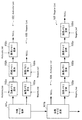
[他の実施の形態例]
図23は、本発明の第2の実施の形態に係る画像処理装置の要部構成を示すブロック図である。
[Other Embodiments]
FIG. 23 is a block diagram showing a main configuration of an image processing apparatus according to the second embodiment of the present invention.
図23に示す画像処理装置では、2つのエンコーダ20aおよび20bにより並行してエンコードを行うことが可能となっている。例えば、2つのエンコーダ20aおよび20bに対して、撮像画像などの同一の動画像データおよび音声データを供給して、それぞれに異なる画像サイズでのエンコードを実行させ、一方の符号化ストリームを磁気テープに記録し、他方をメモリカードなどの他の記録媒体に記録する、あるいはネットワークを通じて外部機器に送信することが可能となっている。
In the image processing apparatus shown in FIG. 23, encoding can be performed in parallel by the two
この画像処理装置では、第1の実施の形態と同様に、エンコーダ20aおよび20bによる画像メモリ40へのアクセスは、メモリ制御部50を通じて行われる。これにより、一方のエンコードを続行させたままで、他方のエンコードを停止させて画像サイズを変更し、エンコードを再開させることが可能となる。
In this image processing apparatus, as in the first embodiment, access to the
図24は、本発明の第3の実施の形態に係る画像処理装置の要部構成を示すブロック図である。
図24に示す画像処理装置では、2つのデコーダ30aおよび30bにより並行してデコードを行うことが可能となっている。例えば、2つのデコーダ30aおよび30bに対して、それぞれ異なる符号化ストリームを供給してデコードを並行して実行させ、双方から出力される動画像データを合成し、1つの画面に合成画像を表示させることが可能となっている。
FIG. 24 is a block diagram showing the main configuration of an image processing apparatus according to the third embodiment of the present invention.
In the image processing apparatus shown in FIG. 24, decoding can be performed in parallel by the two
この画像処理装置では、第1の実施の形態と同様に、デコーダ30aおよび30bによる画像メモリ40へのアクセスは、メモリ制御部50を通じて行われる。これにより、一方のデコードを続行させたままで、他方のデコードを停止させて画像サイズを変更し、デコードを再開させることが可能となる。
In this image processing apparatus, as in the first embodiment, access to the
また、本発明は、動画像のエンコード・デコードに限らず、複数系統の画像処理を、同一の画像メモリを共用して実行する場合に適用することが可能である。このような画像処理としては、例えば画像の拡大・縮小、合成、画質補正などが適用可能である。さらに、1系統の画像処理を行う場合に本発明を適用した場合にも、画像メモリの仕様に関係なく、画像処理エンジンの構成が簡素化されるという効果が得られる。 Further, the present invention is not limited to encoding / decoding of moving images, but can be applied to a case where a plurality of systems of image processing are executed while sharing the same image memory. As such image processing, for example, image enlargement / reduction, composition, image quality correction, and the like can be applied. Furthermore, even when the present invention is applied to the case where one system of image processing is performed, the effect of simplifying the configuration of the image processing engine can be obtained regardless of the specifications of the image memory.
また、本発明は、画像処理や画像メモリへのアクセス管理などの処理が、OSを搭載しない組み込み型システムにより実行される場合に特に好適である。しかし、汎用OSを搭載した組み込み型システムに本発明を適用することも可能である。この場合、メモリ制御部50に相当する処理プログラムが汎用OS上で実行されるが、このプログラムは画像メモリ管理に特化しているため、汎用OSによる画像メモリの管理処理より性能が優れていると言える。
In addition, the present invention is particularly suitable when processing such as image processing and image memory access management is executed by an embedded system that does not include an OS. However, the present invention can be applied to an embedded system equipped with a general-purpose OS. In this case, a processing program corresponding to the
なお、上記の各実施の形態で示したメモリ制御部50の処理機能は、コンピュータによって実現することができる。その場合、メモリ制御部50が有すべき機能の処理内容を記述したプログラムが提供される。そのプログラムをコンピュータで実行することにより、上記処理機能がコンピュータ上で実現される。処理内容を記述したプログラムは、コンピュータで読み取り可能な記録媒体に記録しておくことができる。このような記録媒体としては、磁気記録装置、光ディスク、光磁気記録媒体、半導体メモリなどがある。
Note that the processing functions of the
プログラムを流通させる場合には、例えば、半導体メモリなどからなる可搬型記録媒体にそのプログラムが記録され、この可搬型記録媒体が販売される。また、プログラムをサーバコンピュータの記憶装置に格納しておき、ネットワークを介して、サーバコンピュータから他のコンピュータにそのプログラムを転送することもできる。 When distributing the program, for example, the program is recorded on a portable recording medium such as a semiconductor memory, and the portable recording medium is sold. It is also possible to store the program in a storage device of a server computer and transfer the program from the server computer to another computer via a network.
プログラムを実行するコンピュータは、例えば、可搬型記録媒体に記録されたプログラムまたはサーバコンピュータから転送されたプログラムを、自己の記憶装置に格納する。そして、コンピュータは、自己の記憶装置からプログラムを読み取り、プログラムに従った処理を実行する。なお、コンピュータは、可搬型記録媒体から直接プログラムを読み取り、そのプログラムに従った処理を実行することもできる。 The computer that executes the program stores, for example, the program recorded on the portable recording medium or the program transferred from the server computer in its own storage device. Then, the computer reads the program from its own storage device and executes processing according to the program. The computer can also read the program directly from the portable recording medium and execute processing according to the program.
10……CPU、20……エンコーダ、30……デコーダ、40……画像メモリ、41……メモリI/F、41a……ルックアップテーブル、41b……データフォーマット、50……メモリ制御部、51……メモリ領域管理部、52……メモリ確保処理部、53……メモリ解放処理部、54……ルックアップテーブル設定部、55……データフォーマット設定部、56……CPU・I/F、57……エンコーダI/F、58……デコーダI/F
10: CPU, 20: Encoder, 30: Decoder, 40: Image memory, 41: Memory I / F, 41a: Look-up table, 41b: Data format, 50: Memory control unit, 51 ... Memory
Claims (19)
メモリ領域確保手段が、複数の前記画像処理手段のそれぞれの処理のために個別に指定される画像サイズおよび画像枚数の入力を受けて、前記画像サイズに対応するメモリ領域を前記画像メモリ上の空き領域に前記画像枚数分だけ個別に割り当てて確保し、確保した前記メモリ領域を示すアドレスを出力するメモリ領域確保ステップと、
メモリ領域管理手段が、前記メモリ領域確保ステップで確保された前記各メモリ領域の識別情報と、少なくとも前記アドレスを含む、前記メモリ領域にアクセスするためのアクセス情報との対応関係を、前記メモリ領域ごとに記憶したメモリ領域情報を生成するメモリ領域情報生成ステップと、
前記メモリ領域管理手段が、前記各メモリ領域に対する前記各画像処理手段からの使用要求および返却要求を受け付けて、前記各メモリ領域の使用状態を前記メモリ領域情報を用いて管理するメモリ領域管理ステップと、
を含むことを特徴とするメモリ管理方法。 In a memory management method for sharing a single image memory as a work area by a plurality of image processing means and executing the processing by each of the image processing means in parallel,
The memory area securing means receives the input of the image size and the number of images individually designated for each processing of the plurality of image processing means, and frees up a memory area corresponding to the image size in the image memory. A memory area securing step for individually allocating and securing the number of images in the area and outputting an address indicating the secured memory area;
The memory area management means determines the correspondence between the identification information of each memory area secured in the memory area securing step and the access information for accessing the memory area including at least the address, for each memory area. A memory area information generation step for generating memory area information stored in
A memory area management step in which the memory area management means receives use requests and return requests from the image processing means for the memory areas, and manages the use state of the memory areas using the memory area information; ,
A memory management method.
前記メモリ領域管理ステップは、前記画像処理手段からの前記使用要求を受けると、前記第2の線形リストの先頭の前記メモリ領域情報を取り出して、前記第1の線形リストの最後尾に接続するとともに、当該メモリ領域情報を識別するための識別番号を要求元の前記画像処理手段に出力するステップを含む、
ことを特徴とする請求項3記載のメモリ管理方法。 The memory area information generating step includes the step of sequentially connecting the memory area information corresponding to the memory area secured in the memory area securing step to the second linear list,
When the memory area management step receives the use request from the image processing unit, the memory area management step extracts the memory area information at the head of the second linear list and connects it to the tail of the first linear list. Outputting the identification number for identifying the memory area information to the image processing means of the request source,
4. The memory management method according to claim 3, wherein:
前記メモリ領域管理ステップでは、前記メモリ領域確保ステップで出力された前記ノード番号を前記メモリ領域情報内に記憶する、
ことを特徴とする請求項1記載のメモリ管理方法。 In the memory area securing step, the unit memory area on the image memory is managed in association with the lowest layer node of the binary tree structure, and when the image size is designated, image data for the designated image size The node in the binary tree structure in which one or more unit memory areas capable of storing the data are associated with the child nodes in the lowest layer is extracted, and the node number indicating the extracted node is output to the memory area management means By securing the memory area corresponding to the specified image size,
In the memory area management step, the node number output in the memory area securing step is stored in the memory area information.
The memory management method according to claim 1, wherein:
前記アクセス情報は、前記先頭アドレスと、当該先頭アドレスにより示される前記メモリ領域に対応する画像サイズとを含むことを特徴とする請求項1記載のメモリ管理方法。 In the memory area securing step, the start address of the memory area is output as the address indicating the secured memory area,
2. The memory management method according to claim 1, wherein the access information includes the head address and an image size corresponding to the memory area indicated by the head address.
複数の前記画像処理手段のそれぞれの処理のために個別に指定される画像サイズおよび画像枚数の入力を受けて、前記画像サイズに対応するメモリ領域を前記画像メモリ上の空き領域に前記画像枚数分だけ個別に割り当てて確保し、確保した前記メモリ領域を示すアドレスを出力するメモリ領域確保手段と、
前記メモリ領域確保手段により確保された前記各メモリ領域の識別情報と、少なくとも前記アドレスを含む、前記メモリ領域にアクセスするためのアクセス情報との対応関係を、前記メモリ領域ごとに記憶したメモリ領域情報を保持するとともに、前記各メモリ領域に対する前記各画像処理手段からの使用要求および返却要求を受け付けて、前記各メモリ領域の使用状態を前記メモリ領域情報を用いて管理するメモリ領域管理手段と、
を有することを特徴とする画像処理装置。 In an image processing apparatus in which one image memory is shared as a work area by a plurality of image processing means, and the processing by each of the image processing means can be executed in parallel.
In response to the input of the image size and the number of images individually designated for the processing of each of the plurality of image processing means, a memory area corresponding to the image size is set as a free area on the image memory for the number of images. Memory area securing means for individually allocating and securing, and outputting an address indicating the secured memory area;
Memory area information storing the correspondence between the identification information of each memory area secured by the memory area securing means and the access information for accessing the memory area, including at least the address, for each memory area A memory area management means for receiving a use request and a return request from each image processing means for each memory area, and managing a use state of each memory area using the memory area information;
An image processing apparatus comprising:
前記メモリ領域確保手段は、前記メモリ領域管理手段からの前記解放要求を受けると、対応する前記メモリ領域を再び空き領域に設定する、
ことを特徴とする請求項10記載の画像処理装置。 When the processing of the image processing means is stopped, the memory area management means outputs a request to release the memory area reserved for the processing of the image processing means to the memory area securing means to respond Erase the memory area information,
The memory area securing means, upon receiving the release request from the memory area management means, sets the corresponding memory area as a free area again,
The image processing apparatus according to claim 10.
前記メモリ領域確保手段は、前記メモリ領域管理手段から前記解放要求に応じて、対応する前記メモリ領域を空き領域に設定する、
ことを特徴とする請求項14記載の画像処理装置。 When the processing of the image processing means is stopped, the memory area management means outputs a release request for the memory area corresponding to the memory area information on the corresponding second linear list to the memory area securing means Delete the memory area information,
The memory area securing means sets the corresponding memory area as a free area in response to the release request from the memory area management means.
The image processing apparatus according to claim 14.
前記メモリ領域管理手段は、前記メモリ領域確保手段からの前記ノード番号を前記メモリ領域情報内に記憶する、
ことを特徴とする請求項10記載の画像処理装置。 The memory area securing unit manages a unit memory area on the image memory in association with a lowest-layer node of a binary tree structure, and when the image size is designated, image data for the designated image size The node in the binary tree structure in which one or more unit memory areas capable of storing the data are associated with the child nodes in the lowest layer is extracted, and the node number indicating the extracted node is output to the memory area management means By securing the memory area corresponding to the specified image size,
The memory area management means stores the node number from the memory area securing means in the memory area information;
The image processing apparatus according to claim 10.
前記アクセス情報は、前記先頭アドレスと、当該先頭アドレスにより示される前記メモリ領域に対応する画像サイズとを含むことを特徴とする請求項10記載の画像処理装置。 The memory area securing means outputs a start address of the memory area as the address indicating the secured memory area;
The image processing apparatus according to claim 10, wherein the access information includes the head address and an image size corresponding to the memory area indicated by the head address.
複数の前記画像処理手段のそれぞれの処理のために個別に指定される画像サイズおよび画像枚数の入力を受けて、前記画像サイズに対応するメモリ領域を前記画像メモリ上の空き領域に前記画像枚数分だけ個別に割り当てて確保し、確保した前記メモリ領域を示すアドレスを出力するメモリ領域確保ステップと、
前記メモリ領域確保ステップで確保された前記各メモリ領域の識別情報と、少なくとも前記アドレスを含む、前記メモリ領域にアクセスするためのアクセス情報との対応関係を、前記メモリ領域ごとに記憶したメモリ領域情報を生成するメモリ領域情報生成ステップと、
前記各メモリ領域に対する前記各画像処理手段からの使用要求および返却要求を受け付けて、前記各メモリ領域の使用状態を前記メモリ領域情報を用いて管理するメモリ領域管理ステップと、
を含む処理を前記コンピュータに実行させることを特徴とするメモリ管理プログラム。 In a memory management program for sharing a single image memory as a work area by a plurality of image processing means and causing a computer to execute a memory management process for executing the processes by the image processing means in parallel.
In response to the input of the image size and the number of images individually designated for the processing of each of the plurality of image processing means, a memory area corresponding to the image size is set as a free area on the image memory for the number of images. A memory area securing step for individually assigning and securing, and outputting an address indicating the secured memory area;
Memory area information in which the correspondence between the identification information of each memory area secured in the memory area securing step and the access information for accessing the memory area including at least the address is stored for each memory area A memory area information generation step for generating
A memory area management step for receiving a use request and a return request from each image processing means for each memory area, and managing a use state of each memory area using the memory area information;
A memory management program for causing a computer to execute a process including:
Priority Applications (5)
| Application Number | Priority Date | Filing Date | Title |
|---|---|---|---|
| JP2004040177A JP2005234687A (en) | 2004-02-17 | 2004-02-17 | Memory management method, image processor and memory management program |
| US11/049,851 US20050180643A1 (en) | 2004-02-17 | 2005-02-03 | Memory management method, image processing apparatus, and memory management program |
| EP20050002974 EP1564998A3 (en) | 2004-02-17 | 2005-02-11 | Memory management method, image processing apparatus, and memory management program |
| KR20050012807A KR20060042002A (en) | 2004-02-17 | 2005-02-16 | Memory management method, image processing apparatus and memory management program |
| CNB2005100640386A CN100420296C (en) | 2004-02-17 | 2005-02-17 | Memory management method, image processing apparatus, and memory management program |
Applications Claiming Priority (1)
| Application Number | Priority Date | Filing Date | Title |
|---|---|---|---|
| JP2004040177A JP2005234687A (en) | 2004-02-17 | 2004-02-17 | Memory management method, image processor and memory management program |
Publications (2)
| Publication Number | Publication Date |
|---|---|
| JP2005234687A true JP2005234687A (en) | 2005-09-02 |
| JP2005234687A5 JP2005234687A5 (en) | 2007-01-11 |
Family
ID=34697989
Family Applications (1)
| Application Number | Title | Priority Date | Filing Date |
|---|---|---|---|
| JP2004040177A Abandoned JP2005234687A (en) | 2004-02-17 | 2004-02-17 | Memory management method, image processor and memory management program |
Country Status (5)
| Country | Link |
|---|---|
| US (1) | US20050180643A1 (en) |
| EP (1) | EP1564998A3 (en) |
| JP (1) | JP2005234687A (en) |
| KR (1) | KR20060042002A (en) |
| CN (1) | CN100420296C (en) |
Cited By (4)
| Publication number | Priority date | Publication date | Assignee | Title |
|---|---|---|---|---|
| US8199157B2 (en) | 2007-02-06 | 2012-06-12 | Samsung Electronics Co., Ltd. | System on chip including an image processing memory with multiple access |
| JP2014011714A (en) * | 2012-07-02 | 2014-01-20 | Ntt Docomo Inc | Moving image prediction encoding device, moving image prediction encoding method, moving image prediction encoding program, moving image prediction decoding device, moving image prediction decoding method, and moving image prediction decoding program |
| JP2016158282A (en) * | 2016-04-12 | 2016-09-01 | 株式会社Nttドコモ | Moving image prediction decoding method and moving image prediction decoding apparatus |
| JP2020167492A (en) * | 2019-03-29 | 2020-10-08 | 株式会社デンソーテン | Buffer management device |
Families Citing this family (12)
| Publication number | Priority date | Publication date | Assignee | Title |
|---|---|---|---|---|
| JP3989472B2 (en) * | 2004-07-30 | 2007-10-10 | シャープ株式会社 | Image data processing circuit and image processing apparatus comprising the same |
| US7769274B2 (en) * | 2005-05-06 | 2010-08-03 | Mediatek, Inc. | Video processing and optical recording using a shared memory |
| JP4874162B2 (en) * | 2007-04-27 | 2012-02-15 | ルネサスエレクトロニクス株式会社 | Data expansion apparatus and data expansion method |
| JP4917561B2 (en) * | 2008-03-18 | 2012-04-18 | 株式会社リコー | Image processing device |
| JP2010160585A (en) * | 2009-01-06 | 2010-07-22 | Sony Corp | Server apparatus, information processing method, information processing system |
| GB2483282B (en) * | 2010-09-03 | 2017-09-13 | Advanced Risc Mach Ltd | Data compression and decompression using relative and absolute delta values |
| CN102956238B (en) * | 2011-08-19 | 2016-02-10 | 杜比实验室特许公司 | For detecting the method and apparatus of repeat pattern in audio frame sequence |
| JP2014013506A (en) * | 2012-07-04 | 2014-01-23 | Canon Inc | Information processing apparatus, control method, and program |
| CN103731448B (en) * | 2012-10-11 | 2017-09-26 | 腾讯科技(深圳)有限公司 | A kind of method and system of compressed picture |
| US9299126B2 (en) * | 2013-09-12 | 2016-03-29 | Arm Limited | Image processing apparatus and a method of storing encoded data blocks generated by such an image processing apparatus |
| CN106354811A (en) * | 2016-08-29 | 2017-01-25 | 苏州蓝海彤翔系统科技有限公司 | Method, device and system for processing picture output abnormal conditions |
| CN112188034A (en) * | 2020-09-29 | 2021-01-05 | 北京小米移动软件有限公司 | Image processing method, device, terminal equipment and medium |
Family Cites Families (17)
| Publication number | Priority date | Publication date | Assignee | Title |
|---|---|---|---|---|
| US5915041A (en) * | 1993-03-04 | 1999-06-22 | Unisys Corporation | Method and apparatus for efficiently decoding variable length encoded data |
| JP3278297B2 (en) * | 1994-07-20 | 2002-04-30 | 富士通株式会社 | Data compression method, data decompression method, data compression device, and data decompression device |
| US5920352A (en) * | 1994-10-28 | 1999-07-06 | Matsushita Electric Industrial Co., Ltd. | Image memory storage system and method for a block oriented image processing system |
| US7190284B1 (en) * | 1994-11-16 | 2007-03-13 | Dye Thomas A | Selective lossless, lossy, or no compression of data based on address range, data type, and/or requesting agent |
| US5867166A (en) * | 1995-08-04 | 1999-02-02 | Microsoft Corporation | Method and system for generating images using Gsprites |
| US6008820A (en) * | 1995-08-04 | 1999-12-28 | Microsoft Corporation | Processor for controlling the display of rendered image layers and method for controlling same |
| JPH09322121A (en) | 1996-05-27 | 1997-12-12 | Sony Corp | Decoder for image signal subjected to high efficiency coding |
| WO1998044745A1 (en) * | 1997-03-31 | 1998-10-08 | Sharp Kabushiki Kaisha | Apparatus and method for simultaneous video decompression |
| EP0936813A1 (en) * | 1998-02-16 | 1999-08-18 | CANAL+ Société Anonyme | Processing of digital picture data in a decoder |
| US6366289B1 (en) * | 1998-07-17 | 2002-04-02 | Microsoft Corporation | Method and system for managing a display image in compressed and uncompressed blocks |
| US6208354B1 (en) * | 1998-11-03 | 2001-03-27 | Ati International Srl | Method and apparatus for displaying multiple graphics images in a mixed video graphics display |
| US6411957B1 (en) * | 1999-06-30 | 2002-06-25 | Arm Limited | System and method of organizing nodes within a tree structure |
| EP1243141B1 (en) * | 1999-12-14 | 2011-10-19 | Scientific-Atlanta, LLC | System and method for adaptive decoding of a video signal with coordinated resource allocation |
| US6567091B2 (en) * | 2000-02-01 | 2003-05-20 | Interactive Silicon, Inc. | Video controller system with object display lists |
| US6477612B1 (en) * | 2000-02-08 | 2002-11-05 | Microsoft Corporation | Providing access to physical memory allocated to a process by selectively mapping pages of the physical memory with virtual memory allocated to the process |
| GB0007493D0 (en) * | 2000-03-28 | 2000-05-17 | Tao Group Ltd | Garbage collection |
| US6940909B2 (en) * | 2003-07-29 | 2005-09-06 | Lsi Logic Corporation | Video decoding during I-frame decode at resolution change |
-
2004
- 2004-02-17 JP JP2004040177A patent/JP2005234687A/en not_active Abandoned
-
2005
- 2005-02-03 US US11/049,851 patent/US20050180643A1/en not_active Abandoned
- 2005-02-11 EP EP20050002974 patent/EP1564998A3/en not_active Withdrawn
- 2005-02-16 KR KR20050012807A patent/KR20060042002A/en not_active Application Discontinuation
- 2005-02-17 CN CNB2005100640386A patent/CN100420296C/en not_active Expired - Fee Related
Cited By (7)
| Publication number | Priority date | Publication date | Assignee | Title |
|---|---|---|---|---|
| US8199157B2 (en) | 2007-02-06 | 2012-06-12 | Samsung Electronics Co., Ltd. | System on chip including an image processing memory with multiple access |
| JP2014011714A (en) * | 2012-07-02 | 2014-01-20 | Ntt Docomo Inc | Moving image prediction encoding device, moving image prediction encoding method, moving image prediction encoding program, moving image prediction decoding device, moving image prediction decoding method, and moving image prediction decoding program |
| US9942562B2 (en) | 2012-07-02 | 2018-04-10 | Ntt Docomo, Inc. | Video predictive encoding device, video predictive encoding method, video predictive encoding program, video predictive decoding device, video predictive decoding method, and video predictive decoding program |
| US10116956B2 (en) | 2012-07-02 | 2018-10-30 | Ntt Docomo, Inc. | Video predictive encoding device, video predictive encoding method, video predictive encoding program, video predictive decoding device, video predictive decoding method, and video predictive decoding program |
| US10560711B2 (en) | 2012-07-02 | 2020-02-11 | Ntt Docomo, Inc. | VIDEO PREDICTIVE ENCODING DEVICE, VIDEO PREDICTIVE ENCODING Method, video predictive encoding program, video predictive decoding device, video predictive decoding method, and video predictive decoding program |
| JP2016158282A (en) * | 2016-04-12 | 2016-09-01 | 株式会社Nttドコモ | Moving image prediction decoding method and moving image prediction decoding apparatus |
| JP2020167492A (en) * | 2019-03-29 | 2020-10-08 | 株式会社デンソーテン | Buffer management device |
Also Published As
| Publication number | Publication date |
|---|---|
| KR20060042002A (en) | 2006-05-12 |
| EP1564998A2 (en) | 2005-08-17 |
| CN1658665A (en) | 2005-08-24 |
| EP1564998A3 (en) | 2007-12-26 |
| US20050180643A1 (en) | 2005-08-18 |
| CN100420296C (en) | 2008-09-17 |
Similar Documents
| Publication | Publication Date | Title |
|---|---|---|
| KR20060042002A (en) | Memory management method, image processing apparatus and memory management program | |
| US6697902B1 (en) | Data storage device and interface device for the data storage device | |
| JP2007079774A (en) | Method for constructing file system | |
| JPWO2006025322A1 (en) | Recording device | |
| JP2008065445A (en) | Computer system for saving storage area by integrating same data, storage systems and those control method | |
| US20110317763A1 (en) | Information processing apparatus and information processing method | |
| US8010746B2 (en) | Data processing apparatus and shared memory accessing method | |
| JP4502375B2 (en) | File system and control method thereof | |
| JP5406750B2 (en) | Recording apparatus and control method thereof | |
| JP2008192224A (en) | Data and file system information recording apparatus and recording method | |
| JP2008193345A (en) | Editing device and editing method | |
| JPH08152976A (en) | Access method for storage device | |
| KR101103308B1 (en) | Method and device for generating a menu, and recording medium | |
| JP2008176455A (en) | Information recorder, controller, access device, and access speed guaranteeing system | |
| JP2003059189A (en) | Buffer management method | |
| JP7149809B2 (en) | IMAGE RECORDING DEVICE, CONTROL METHOD AND PROGRAM THEREOF | |
| JP2007281972A (en) | Stream data recording/reproducing apparatus and stream data recording apparatus | |
| JP2007059004A (en) | Information processor and method, program, and recording medium | |
| JP2007081842A (en) | Image managing device | |
| US20080187281A1 (en) | Editing apparatus and editing method | |
| JP4480592B2 (en) | File system | |
| JP2004192402A (en) | Recording method and recording apparatus | |
| JP2007310533A (en) | Nonvolatile storage system, nonvolatile storage device, and file data write-in method | |
| JP2006215639A (en) | Data control method and information processor | |
| JP2001337851A (en) | Device and method for file management |
Legal Events
| Date | Code | Title | Description |
|---|---|---|---|
| A521 | Written amendment |
Free format text: JAPANESE INTERMEDIATE CODE: A523 Effective date: 20061117 |
|
| A621 | Written request for application examination |
Free format text: JAPANESE INTERMEDIATE CODE: A621 Effective date: 20061117 |
|
| A762 | Written abandonment of application |
Free format text: JAPANESE INTERMEDIATE CODE: A762 Effective date: 20090818 |