JP2005084260A - Method for determining conversion data of display panel and measuring instrument - Google Patents
Method for determining conversion data of display panel and measuring instrument Download PDFInfo
- Publication number
- JP2005084260A JP2005084260A JP2003314587A JP2003314587A JP2005084260A JP 2005084260 A JP2005084260 A JP 2005084260A JP 2003314587 A JP2003314587 A JP 2003314587A JP 2003314587 A JP2003314587 A JP 2003314587A JP 2005084260 A JP2005084260 A JP 2005084260A
- Authority
- JP
- Japan
- Prior art keywords
- measurement
- capacitor
- display panel
- luminance
- pixel
- Prior art date
- Legal status (The legal status is an assumption and is not a legal conclusion. Google has not performed a legal analysis and makes no representation as to the accuracy of the status listed.)
- Pending
Links
- 238000006243 chemical reaction Methods 0.000 title claims abstract description 66
- 238000000034 method Methods 0.000 title claims abstract description 32
- 238000005259 measurement Methods 0.000 claims abstract description 122
- 239000003990 capacitor Substances 0.000 claims abstract description 74
- 230000007274 generation of a signal involved in cell-cell signaling Effects 0.000 claims description 18
- 239000011159 matrix material Substances 0.000 claims description 10
- 238000012937 correction Methods 0.000 description 8
- 238000012545 processing Methods 0.000 description 7
- 239000010408 film Substances 0.000 description 5
- 230000007547 defect Effects 0.000 description 3
- 239000004973 liquid crystal related substance Substances 0.000 description 3
- 238000004519 manufacturing process Methods 0.000 description 3
- 238000012986 modification Methods 0.000 description 3
- 230000004048 modification Effects 0.000 description 3
- 229910021420 polycrystalline silicon Inorganic materials 0.000 description 3
- 229920005591 polysilicon Polymers 0.000 description 3
- 238000001514 detection method Methods 0.000 description 2
- 238000010586 diagram Methods 0.000 description 2
- 238000007599 discharging Methods 0.000 description 2
- 230000032683 aging Effects 0.000 description 1
- 229910021417 amorphous silicon Inorganic materials 0.000 description 1
- 239000003086 colorant Substances 0.000 description 1
- 239000013078 crystal Substances 0.000 description 1
- 230000010365 information processing Effects 0.000 description 1
- 238000000691 measurement method Methods 0.000 description 1
- 239000011368 organic material Substances 0.000 description 1
- 230000004044 response Effects 0.000 description 1
- 230000000717 retained effect Effects 0.000 description 1
- 229920006395 saturated elastomer Polymers 0.000 description 1
- 238000012360 testing method Methods 0.000 description 1
- 239000010409 thin film Substances 0.000 description 1
- 230000000007 visual effect Effects 0.000 description 1
Images


Classifications
-
- G—PHYSICS
- G09—EDUCATION; CRYPTOGRAPHY; DISPLAY; ADVERTISING; SEALS
- G09G—ARRANGEMENTS OR CIRCUITS FOR CONTROL OF INDICATING DEVICES USING STATIC MEANS TO PRESENT VARIABLE INFORMATION
- G09G3/00—Control arrangements or circuits, of interest only in connection with visual indicators other than cathode-ray tubes
- G09G3/20—Control arrangements or circuits, of interest only in connection with visual indicators other than cathode-ray tubes for presentation of an assembly of a number of characters, e.g. a page, by composing the assembly by combination of individual elements arranged in a matrix no fixed position being assigned to or needed to be assigned to the individual characters or partial characters
- G09G3/22—Control arrangements or circuits, of interest only in connection with visual indicators other than cathode-ray tubes for presentation of an assembly of a number of characters, e.g. a page, by composing the assembly by combination of individual elements arranged in a matrix no fixed position being assigned to or needed to be assigned to the individual characters or partial characters using controlled light sources
- G09G3/30—Control arrangements or circuits, of interest only in connection with visual indicators other than cathode-ray tubes for presentation of an assembly of a number of characters, e.g. a page, by composing the assembly by combination of individual elements arranged in a matrix no fixed position being assigned to or needed to be assigned to the individual characters or partial characters using controlled light sources using electroluminescent panels
-
- G—PHYSICS
- G09—EDUCATION; CRYPTOGRAPHY; DISPLAY; ADVERTISING; SEALS
- G09G—ARRANGEMENTS OR CIRCUITS FOR CONTROL OF INDICATING DEVICES USING STATIC MEANS TO PRESENT VARIABLE INFORMATION
- G09G3/00—Control arrangements or circuits, of interest only in connection with visual indicators other than cathode-ray tubes
- G09G3/20—Control arrangements or circuits, of interest only in connection with visual indicators other than cathode-ray tubes for presentation of an assembly of a number of characters, e.g. a page, by composing the assembly by combination of individual elements arranged in a matrix no fixed position being assigned to or needed to be assigned to the individual characters or partial characters
-
- G—PHYSICS
- G09—EDUCATION; CRYPTOGRAPHY; DISPLAY; ADVERTISING; SEALS
- G09G—ARRANGEMENTS OR CIRCUITS FOR CONTROL OF INDICATING DEVICES USING STATIC MEANS TO PRESENT VARIABLE INFORMATION
- G09G2300/00—Aspects of the constitution of display devices
- G09G2300/08—Active matrix structure, i.e. with use of active elements, inclusive of non-linear two terminal elements, in the pixels together with light emitting or modulating elements
- G09G2300/0809—Several active elements per pixel in active matrix panels
-
- G—PHYSICS
- G09—EDUCATION; CRYPTOGRAPHY; DISPLAY; ADVERTISING; SEALS
- G09G—ARRANGEMENTS OR CIRCUITS FOR CONTROL OF INDICATING DEVICES USING STATIC MEANS TO PRESENT VARIABLE INFORMATION
- G09G2320/00—Control of display operating conditions
- G09G2320/02—Improving the quality of display appearance
- G09G2320/029—Improving the quality of display appearance by monitoring one or more pixels in the display panel, e.g. by monitoring a fixed reference pixel
Landscapes
- Engineering & Computer Science (AREA)
- Physics & Mathematics (AREA)
- Computer Hardware Design (AREA)
- General Physics & Mathematics (AREA)
- Theoretical Computer Science (AREA)
- Control Of Indicators Other Than Cathode Ray Tubes (AREA)
- Control Of El Displays (AREA)
- Devices For Indicating Variable Information By Combining Individual Elements (AREA)
- Electroluminescent Light Sources (AREA)
Abstract
Description
本発明は、表示パネルの変換データ決定方法に関し、特に自己発光素子を有するTFTアレイ表示パネルにおける輝度のばらつきを補正する輝度変換データの決定方法、およびこれを利用した表示装置に関する。 The present invention relates to a method for determining conversion data for a display panel, and more particularly to a method for determining luminance conversion data for correcting variations in luminance in a TFT array display panel having a self-luminous element, and a display device using the same.
フラットテレビ、パソコンのモニタ、携帯電話の表示装置等に使用されるフラット表示パネルには、早い動きの画像に対応可能で、鮮やかな色が再現できることが求められる。このような要求から、近年、応答速度の速い薄膜トランジスタ(TFT)アレイと、表示色域が広い有機EL素子など自己発光素子を用いたアクティブ型の表示パネルが注目されている。 Flat display panels used in flat TVs, personal computer monitors, mobile phone display devices, and the like are required to be able to handle fast-moving images and reproduce vivid colors. In recent years, attention has been paid to a thin film transistor (TFT) array having a high response speed and an active display panel using a self-light emitting element such as an organic EL element having a wide display color gamut.
自己発光素子とは、素子に流れる電流量に従って光を発生する発光素子である。このような自己発光素子を利用した表示パネルに使用するTFTアレイは、従来の代表的なフラット表示パネルである液晶パネル用のTFTアレイに比べて、格段に大きな電流を流す必要がある。自己発光素子を用いた表示パネル用のTFTアレイに、従来から液晶表示パネルで使用されていたアモルファスシリコン膜を用いると、キャリアの移動度が低いため十分な駆動電流が得られない場合が多い。また、ゲート絶縁膜内のチャージアップにより、FETのスレッショルド電圧が経年変化して、各画素の輝度のばらつきが大きくなる。このため、自己発光素子を用いた表示パネルのTFTアレイには、キャリア移動度が高いため高い駆動電流が得やすく、経年変化が小さい低温ポリシリコン膜が用いられることが多い。しかし、低温ポリシリコン膜は、FETチャネル領域の結晶の出来具合に依存して各FETの電流−電圧特性が1割近く変動する。しかも、かかる変動はパネル内の距離が近いFETどうしでもばらつきが大きい。すなわち、低温ポリシリコン膜を利用したTFTアレイは、製造時の各画素の輝度のばらつきが大きい。加えて、発光素子自体の発光特性の経年変化も無視できない。特に、EL素子は有機材料を使用しているため、使用温度や駆動電流等の使用条件により経年変化の度合いが大きく異なる。このような発光輝度のばらつきは、画像ムラや色味の変化という表示パネルの欠陥原因となる。 A self-light-emitting element is a light-emitting element that generates light according to the amount of current flowing through the element. A TFT array used for a display panel using such a self-light emitting element needs to pass a much larger current than a TFT array for a liquid crystal panel, which is a conventional typical flat display panel. When an amorphous silicon film conventionally used in a liquid crystal display panel is used for a TFT array for a display panel using a self-luminous element, a sufficient driving current cannot be obtained in many cases because of low carrier mobility. Also, due to the charge-up in the gate insulating film, the threshold voltage of the FET changes with time, and the variation in luminance of each pixel increases. For this reason, a TFT array of a display panel using a self-luminous element often uses a low-temperature polysilicon film that easily obtains a high driving current because of high carrier mobility and has little secular change. However, in the low-temperature polysilicon film, the current-voltage characteristic of each FET varies by nearly 10% depending on the quality of the crystal in the FET channel region. Moreover, such fluctuations vary greatly between FETs that are close in the panel. That is, a TFT array using a low-temperature polysilicon film has a large variation in luminance of each pixel during manufacturing. In addition, the secular change of the light emission characteristics of the light emitting element itself cannot be ignored. In particular, since an EL element uses an organic material, the degree of aging varies greatly depending on use conditions such as a use temperature and a drive current. Such variations in light emission luminance cause defects in the display panel such as image unevenness and color change.
このため、従来、自己発光素子を用いた表示パネルは、製造時や使用時に、適宜、各画素の発光輝度のばらつきの測定を行って補正する必要がある。表示パネルの輝度を測定および補正を行う装置としては、特許文献1に示す装置がある。この装置では、液晶表示パネルの内部または外部に設けたセンサによって、テストパターンを読み取り、表示パネルの光出力特性を測定し補正データを更新する装置である。
また、特許文献2に開示されている技術は、EL素子の駆動電流を測定してEL表示パネルの欠陥を判定する技術である。すなわち、図1のEL表示パネル108ような、画素を選択する画素選択トランジスタ131と、キャパシタ130と、キャパシタ130の電圧に応じた駆動電流を流す駆動トランジスタ118と、自己発光素子(EL素子)115により構成されている表示パネルのTFTアレイの画素117において、このキャパシタ130を充電した時と、完全に放電した後の、発光素子115の駆動電流を測定してその差分をとることにより測定画素の正確な駆動電流を求め、表示パネルの欠陥を判定する技術である。
For this reason, conventionally, a display panel using a self-light-emitting element needs to be corrected by measuring variations in light emission luminance of each pixel as appropriate at the time of manufacture and use. As an apparatus for measuring and correcting the luminance of the display panel, there is an apparatus disclosed in
The technique disclosed in
上述した方法では、測定画素の駆動電流を測定後、測定画素のキャパシタを完全に放電する、すなわち駆動トランジスタのスレッショルド電圧以下になるまで放電してから、次の画素を測定しなければならないため、連続して画素を測定するためには、画素測定間で相当の時間が必要となる。また、EL素子自体にも図6の等価回路で示すようなキャパシタンス成分143とインピーダンス成分141を有するため、駆動電流印加開始から定常状態(駆動電流がほぼ一定となる状態)となるまでには時定数に応じた時間が必要となる。このため、表示パネルのような多数の画素を連続して測定を行うと、非常に時間がかかるという問題がある。
ところで、人間の視覚の特性として、近くの画素どうしの輝度の違いは画像ムラや色味の変化として目に付くが、離れた画素どうしの輝度は多少異なっていても目に付かない。すなわち、輝度ばらつきを補正するためには、近くの画素どうしの相対的な輝度の違いを測定できればよい。このため、輝度ばらつきの補正のためには、絶対的な測定を行う必要はないため、従来よりも簡便で高速な測定方法が求められていた。
In the above-described method, after measuring the driving current of the measurement pixel, the capacitor of the measurement pixel must be completely discharged, that is, discharged until it becomes lower than the threshold voltage of the driving transistor, and then the next pixel must be measured. In order to continuously measure pixels, a considerable amount of time is required between pixel measurements. In addition, since the EL element itself also has a
By the way, as a human visual characteristic, a difference in luminance between nearby pixels is noticeable as image unevenness or a change in color tone, but it is not noticeable even if the luminance between distant pixels is slightly different. That is, in order to correct the luminance variation, it is only necessary to measure the relative luminance difference between neighboring pixels. For this reason, since it is not necessary to perform absolute measurement in order to correct luminance variations, a simpler and faster measurement method than before has been demanded.
本発明は、キャパシタと前記キャパシタの電圧により電流または電圧の制御を行う駆動回路と前記駆動回路により駆動する自己発光素子とを有する複数の画素をマトリクス状に配置した表示パネルと、輝度データを変換データに基づいて変換したアナログ電圧を前記キャパシタに与える輝度信号発生手段とを有する表示装置の変換データ決定方法であって、測定画素以外の画素の前記キャパシタが完全に放電していない時の、前記表示パネルの発光素子の第1の駆動電流を求める第1測定ステップと、前記測定画素のキャパシタを前記アナログ電圧に充電する充電ステップと、前記測定画素のキャパシタが前記アナログ電圧に充電している時に、前記表示パネルの発光素子の第2の駆動電流を測定する第2測定ステップと、前記第1の駆動電流と前記第2の駆動電流の差から、前記測定画素の駆動電流を求める駆動電流算出ステップと、前記駆動電流に基づいて前記変換データを求めるデータ算出ステップとを有することを特徴とする表示パネルの変換データ決定方法により上記課題を解決する。 The present invention converts a luminance data into a display panel having a plurality of pixels arranged in a matrix having a capacitor, a drive circuit that controls current or voltage by the voltage of the capacitor, and a self-light emitting element driven by the drive circuit A conversion data determination method for a display device having a luminance signal generating means for applying an analog voltage converted based on data to the capacitor, wherein the capacitors of pixels other than the measurement pixel are not completely discharged. A first measurement step for obtaining a first drive current of a light emitting element of the display panel; a charging step for charging a capacitor of the measurement pixel to the analog voltage; and a capacitor of the measurement pixel being charged to the analog voltage. A second measurement step of measuring a second drive current of the light emitting element of the display panel; and the first drive current. And a second drive current calculation step for obtaining a drive current of the measurement pixel, and a data calculation step for obtaining the conversion data based on the drive current. The above problem is solved by a conversion data determination method.
すなわち、測定画素の測定に先立って表示パネルの発光素子の駆動電流を測定しておき、測定画素を駆動したときの表示パネルの発光素子の駆動電流との差分をとって測定画素の発光画素の駆動電流を求める方法をとることにより、測定前にキャパシタの放電が十分でない画素が表示パネル内に存在していたとしても、かかる画素の駆動電流をキャンセルした測定ができ、画素間の特性のばらつきを高速に測定することが可能となる。さらに、発光素子駆動前の測定を所定画素毎に行い、測定結果から未測定画素の駆動前電流値を補間して求めることにより、さらに高速な測定が可能となる。この場合、各画素の特性にばらつきがあるため、補間によって正確な駆動前電流値を求めることはできないが、放電量に応じて絶対的なばらつきが小さくなるため、近傍画素どうしではばらつきの影響は無視できる。 That is, prior to measurement of the measurement pixel, the drive current of the light emitting element of the display panel is measured, and the difference from the drive current of the light emission element of the display panel when the measurement pixel is driven is taken to determine the light emission pixel of the measurement pixel. By adopting a method for obtaining the drive current, even if there is a pixel in the display panel that does not have sufficient capacitor discharge before the measurement, measurement can be performed with the drive current of the pixel canceled, and variations in characteristics between pixels Can be measured at high speed. Furthermore, the measurement before driving the light emitting element is performed for each predetermined pixel, and the current value before driving of the unmeasured pixel is interpolated and obtained from the measurement result, thereby enabling a higher speed measurement. In this case, since the characteristics of each pixel vary, an accurate current value before driving cannot be obtained by interpolation, but the absolute variation becomes smaller depending on the discharge amount. Can be ignored.
また、本発明は、TFTアレイと自己発光素子とを有する表示パネルと、輝度データを変換データに変換して輝度信号を発生する輝度信号発生手段と、前記輝度信号により前記自己発光素子を駆動する駆動手段と、前記TFTアレイの発光素子の駆動電流および発光輝度のいずれかまたは両方を測定する測定手段とを有する表示パネルの前記変換データの決定方法であって、測定画素の前記自己発光素子を駆動するステップと、前記測定画素の駆動電流が飽和状態に達する前に前記測定を行うステップと、前記測定の結果に基づいて前記変換データを決定するステップとを有することを特徴とする表示パネルの変換データ決定方法により上記課題を解決する。すなわち、測定画素の発光輝度や駆動電流が飽和状態(発光輝度や測定電流が素子駆動時の定常値となること)になる前に測定を行うことにより、さらに高速な測定が可能となる。 According to another aspect of the present invention, there is provided a display panel having a TFT array and a self-luminous element, luminance signal generating means for converting luminance data into converted data to generate a luminance signal, and driving the self-luminous element by the luminance signal. A method for determining the conversion data of a display panel, comprising: a driving unit; and a measuring unit that measures either or both of a driving current and a light emission luminance of a light emitting element of the TFT array, A display panel comprising: a driving step; a step of performing the measurement before a driving current of the measurement pixel reaches a saturation state; and a step of determining the conversion data based on a result of the measurement. The above problem is solved by a conversion data determination method. That is, the measurement can be performed at a higher speed by performing the measurement before the light emission luminance and the drive current of the measurement pixel are saturated (the light emission luminance and the measurement current become steady values when the element is driven).
本発明により、表示パネルの輝度ばらつきの補正を高速に行うことが可能となる。 According to the present invention, it is possible to correct the luminance variation of the display panel at high speed.
以下に添付図面を参照して、本発明の好適実施形態となる表示装置について詳細に説明する。なお、本実施例では自己発光素子としてEL素子を使用しているが、本発明はEL表示パネルに限定されるものではなく、発光ダイオードを利用した表示装置などの他の自己発光素子を利用した表示パネルにも使用することができる。 Hereinafter, a display device according to a preferred embodiment of the present invention will be described in detail with reference to the accompanying drawings. In this embodiment, an EL element is used as a self-emitting element. However, the present invention is not limited to an EL display panel, and other self-emitting elements such as a display device using a light-emitting diode are used. It can also be used for display panels.
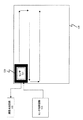
図1は、本発明に係る表示装置の構成概要図を示す。表示装置は、パネルの制御部100とEL表示パネル108からなる。制御部100は、EL表示パネル108のシフトレジスタ109、110に接続された選択手段である画素選択回路104と、輝度データの外部入力とEL表示パネル108の輝度信号線112に接続され各画素ごとの変換データを有する輝度信号発生回路102と、測定手段である電流計101と、電流計101を介して共通線119に接続された駆動手段である電源103と、電流計101に接続され情報処理回路とメモリを有する変換データ決定手段であるデータ処理装置105によって構成されている。輝度信号発生回路102には、図7に示すように、各画素(行番号と列番号で表示)ごとに、小さな輝度に対応する輝度データ10と大きな輝度に対応する輝度250に相当する変換データが格納されている変換テーブルを有する。
FIG. 1 is a schematic configuration diagram of a display device according to the present invention. The display device includes a
また、EL表示パネル108は、マトリクス状に配置された複数の画素117と、画素を選択するデータ線111およびゲート線116と、データ線111およびゲート線116にそれぞれ接続されたシフトレジスタ109、110とにより構成される。画素117は、データ線111およびゲート線116に接続された画素選択トランジスタ
Q1 131と、画素選択トランジスタ131と共通線119に接続されたキャパシタC1 130と、EL素子115と、キャパシタ130と画素選択トランジスタ131とEL素子115に接続された駆動トランジスタQ2 118により構成される。本実施例では、駆動回路として定電流回路を用いているが、電圧制御回路を用いても良い。
The
次に、図1の表示装置の動作について説明する。表示装置には、通常表示モードと補正モードがある。まず、通常表示モードでは、外部から入力された画像信号(画素位置データと輝度データ)に応じて、画素選択手段104が画素位置信号を出力し、シフトレジスタ109および110が画素位置に対応するデータ線とゲート線を選択する。例えば、ゲート線116とデータ線111を選択すると、交点にあたる画素117が選択される。同時に、輝度信号発生回路102は、入力された輝度データに相当するアナログ電圧を、各画素に対応する変換データ(輝度データ10と輝度データ250)から計算して、輝度信号線112に供給する。たとえば、行=0、列=0の画素で、入力された輝度データが150の場合、2.17V(=1+(3−1)/(250−10)×(150−10))となる。輝度信号線112の輝度信号は、画素選択回路104により選択されたデータ線111に供給される。一方、選択された画素117では、画素選択トランジスタ131がオン状態になって、データ線111上の輝度信号によりキャパシタ130が充電され、その後、画素選択トランジスタ131がオフ状態になることにより前記電圧が保持される。キャパシタ130の電圧によって定電流回路である駆動トランジスタ118の電流が制御され、駆動電流がEL素子115に印加される。EL素子115は、駆動電流の電流量に応じた発光量で発光する。
Next, the operation of the display device of FIG. 1 will be described. The display device has a normal display mode and a correction mode. First, in the normal display mode, the
なお、本実施例では、輝度データは0および10〜250の範囲しかとらないため、変換データとして輝度データ10と輝度データ250の変換値を用いているが、変換データとしてどの輝度データを用いるかは、輝度データの数値範囲により適宜選択可能である。本実施例では、補間に線形補間を用いることから、図4のように輝度データに対して駆動電流(キャパシタ印加電圧に比例)がリニアな特性をもつ領域の下限値と上限値に相当する輝度データを選択することが望ましいが、非線形補正を用いることにより非線形特性をもつ領域を利用することも可能である。
In this embodiment, since the luminance data is only in the range of 0 and 10 to 250, the conversion value of the
次に、補正モードの動作について説明する。なお、EL表示パネル108内の構成部品の動作は通常モードと同じであるため、説明を省略する。はじめに、輝度信号線112に0Vの輝度信号を与え、各画素の選択トランジスタ131を画素選択回路104により順次選択して、EL表示パネル108の全てのキャパシタ131を初期化する。初期化が終わった状態で、電流計101に流れる電流をデータ処理装置105のメモリに記録する。次に、画素選択回路104によって測定する測定画素117を選択する。このとき、輝度信号発生回路102から輝度データ10に相当するアナログ電圧が輝度信号線112に印加される。このとき、電流計101に流れる電流をデータ処理装置105のメモリに記録する。メモリに記録されたEL素子115駆動前の電流と駆動後の電流の差をとることによって、測定画素117の駆動電流Imin1を求めることができる。このとき、図8に示すようにImin1が予め設定された電流値Imin0の8割しかない場合には、輝度信号発生回路102の輝度データ10の変換データを1.25倍(=1/0.8)する。
Next, the operation in the correction mode will be described. Note that the operation of the components in the
次に輝度信号発生回路102が輝度信号線112に0Vを与えて、キャパシタ130を放電する。キャパシタ130が完全に放電する、すなわち、キャパシタ130の電圧が駆動トランジスタ118のスレッショルド電圧になるまで放電を行うと時間がかかるため、スレッショルド電圧まで放電する前に当該画素の画素選択トランジスタ131をオフにして、次の測定画素に対して同様の測定を行う。このとき、画素117のキャパシタ130の残留電位により画素117の駆動トランジスタ118には、所定電流が流れ続けるため、次の測定画素のEL素子を駆動する前に、電流計101に流れる電流をデータ処理装置105のメモリに記録しておき、駆動時の電流との差をとることによって、次の測定画素の駆動電流を求める。このように測定画素のキャパシタが完全に放電する前に、次の画素の測定を開始することにより、変換データを高速に決定することができる。
Next, the luminance
測定が必要な画素について輝度データ10の測定が終了した後、パネルを初期化する。そして、同様なプロセスで輝度データ250に関する測定および変換データ決定を行う。すなわち、図8に示すように、輝度データ250に相当する輝度信号をキャパシタ131に印加したときの駆動電流Imax1を求め、予め設定された電流値Imin1と比較して輝度信号発生回路102の輝度データ250の変換値を修正する。このようにして、図8の実線で示す特性をもつ画素を、破線で示すような所定の特性に補正することができる。
After the measurement of the
図2に、本実施例における電流計101の測定ポイントを示す。図において401・402・403・404は測定画素のEL素子に駆動電流を流す前に電流計101に流れる電流であり、411・412・413・414は測定画素のEL素子を駆動した状態における駆動電流である。このように測定画素の測定後、キャパシタC1の放電を完全に行わずに次の画素の測定を行うため、測定画素のEL素子を駆動する前の状態の電流計101に流れる電流は次第に増加していく。
In FIG. 2, the measurement point of the
各画素ごとにキャパシタの放電特性が異なるため、厳密には電流の増加量は一定ではないが、輝度や駆動電流のばらつき補正のための測定に十分な測定および補正精度が維持できればよいため、電流増加量を一定とみなしても実用上の問題は生じない。このため、本実施例の表示装置においては、測定前の電流を画素毎に実測せずに、数画素毎に測定前電流を測定し、直近の実測駆動電流から線形補間して測定画素の測定前電流を求めるモードを有する。このモードを選択すると、例えば、駆動電流値401を測定した後は、駆動電流値404の測定まで、測定画素のEL素子駆動前の表示パネル108に流れる駆動電流の実測を行わず、データ処理装置105が差分算出を行う段階で、駆動電流値401・404の実測値から駆動電流値402・403を補間して求める。このように、測定画素の非駆動時の電流の測定回数を減らすことにより、さらに高速に変換データを決定することができる。
Strictly speaking, the amount of increase in current is not constant because the discharge characteristics of the capacitor differ from pixel to pixel, but it is only necessary to maintain sufficient measurement and correction accuracy for measurement to correct variations in brightness and drive current. Even if the increase amount is regarded as constant, there is no practical problem. Therefore, in the display device of this embodiment, the current before measurement is not measured for each pixel, the current before measurement is measured every several pixels, and the measurement pixel is measured by linear interpolation from the latest measured drive current. It has a mode for obtaining the pre-current. When this mode is selected, for example, after measuring the drive
本実施例では、表示装置内に測定手段および変換データ決定手段を有するため、装置製造時のみならず使用時にも適宜測定を行って駆動電流のばらつきを補正することができる。このため、表示パネル108の各画素107ごとにカレントミラー回路などの自己補正回路を設けるといった、ばらつき補正手段を設ける必要がないため、装置構成が簡略化でき、安価な装置を提供することができる。
In this embodiment, since the display device includes the measuring means and the conversion data determining means, it is possible to correct the drive current variation by performing appropriate measurement not only during the manufacture of the device but also during use. For this reason, it is not necessary to provide variation correction means such as providing a self-correction circuit such as a current mirror circuit for each pixel 107 of the
また、本実施例の制御部100を表示装置から分離して、独立した測定器とすることができる。この場合には、通常表示時に使用する輝度信号発生回路102、電源103、画素選択回路104は表示装置に、変換データ決定時に使用する輝度信号発生回路102、電源103、画素選択回路104は測定器に設ける。測定器の構成・動作は上述した補正モードと同様であるが、測定によって決定された変換データを外部接続された表示装置に内蔵された輝度信号発生回路に送信する必要があるため、測定器の輝度信号発生回路102に出力装置を設ける必要がある。
Moreover, the
上述したような測定画素のEL素子を駆動する前と駆動中の測定値の差分を求める方法は、特許文献1で示したような輝度のみを直接測定する方法にも適用できる。図5は本実施例の表示装置に付加する輝度測定装置の概要を示した図である。図1の装置構成に加え、EL表示パネル108上を走査する輝度センサ121、輝度センサ121に接続されセンサ121からの出力信号から輝度を検出する輝度検出回路122、およびセンサ121の動作を司るセンサ制御回路123が付加される。センサ121の周囲には遮光手段120を設け、センサ121が測定画素近傍の画素からの光のみを検知できるような構成となっている。
The method for obtaining the difference between the measurement values before and during driving the EL element of the measurement pixel as described above can also be applied to the method of directly measuring only the luminance as shown in
輝度測定を付加した装置の動作を説明する。輝度測定以外の動作は前述した装置と同じであるため、説明を省略する。まず、センサ制御回路123がセンサ121を測定画素上に移動させる。そして、測定画素117の駆動前に輝度を測定してデータ処理装置105のメモリに記憶する。次に輝度データ10と輝度データ250に相当する駆動電流で測定画素117のEL素子115を駆動し、駆動時の輝度を測定し、輝度信号発生回路102の変換データを補正する。そして、測定画素117のキャパシタ130を放電し、完全に放電する前に次の画素の測定を順次行う。
The operation of the apparatus to which luminance measurement is added will be described. Since the operation other than the luminance measurement is the same as that of the above-described apparatus, the description thereof is omitted. First, the
また、図3のように、測定画素の駆動電流や発光輝度が定常状態に達する前であって、駆動電流印加開始から所定時間後に、各画素の駆動電流または発光輝度を測定することによって、より高速に変換データの決定を行うことができる。この場合、定常状態における正確な駆動電流や発光輝度は測定できないが、電流印加開始から所定時間後の駆動電流・発光輝度と、定常状態における駆動電流・発光輝度とは比例関係にあるため、過渡状態にあるときの測定値を用いて変換データの補正を行うことができる。 Further, as shown in FIG. 3, by measuring the drive current or the light emission luminance of each pixel before the drive current and the light emission luminance of the measurement pixel reach a steady state and after a predetermined time from the start of the drive current application, Conversion data can be determined at high speed. In this case, accurate drive current and emission brightness in the steady state cannot be measured, but the drive current and emission brightness after a predetermined time from the start of current application are proportional to the drive current and emission brightness in the steady state. The conversion data can be corrected using the measured value when in the state.
なお、上述した本実施例およびその変形例は、特許請求の範囲に記載した本発明の説明のための一実施形態にすぎず、特許請求の範囲で示した権利範囲内において種々の変形を行うことができることは、当業者にとって明らかである。 It should be noted that the above-described embodiment and its modifications are merely an embodiment for explaining the present invention described in the claims, and various modifications are made within the scope of the right indicated in the claims. It will be apparent to those skilled in the art that this is possible.
最後に、本発明の代表的な実施態様を以下に示す。
(実施態様1)
キャパシタと、前記キャパシタの電圧により電流または電圧の制御を行う駆動回路と、前記駆動回路により駆動する自己発光素子とを有する複数の画素をマトリクス状に配置した表示パネルと、
輝度データを変換データに基づいて変換したアナログ電圧を前記キャパシタに与える輝度信号発生手段とを有する表示装置の前記変換データの決定方法であって、
測定画素以外の画素の前記キャパシタが完全に放電していない時の、前記表示パネルの発光素子の第1の駆動電流を求める第1測定ステップと、
前記測定画素のキャパシタを前記アナログ電圧に充電する充電ステップと、
前記測定画素のキャパシタが前記アナログ電圧に充電している時に、前記表示パネルの発光素子の第2の駆動電流を測定する第2測定ステップと、
前記第1の駆動電流と前記第2の駆動電流の差から、前記測定画素の駆動電流を求める駆動電流算出ステップと、
前記駆動電流に基づいて前記変換データを求めるデータ算出ステップと、
を有することを特徴とする表示パネルの変換データ決定方法。
Finally, representative embodiments of the present invention are shown below.
(Embodiment 1)
A display panel in which a plurality of pixels each having a capacitor, a drive circuit that controls current or voltage according to the voltage of the capacitor, and a self-light-emitting element driven by the drive circuit are arranged in a matrix;
A method for determining the conversion data of a display device, comprising: luminance signal generation means for applying to the capacitor an analog voltage obtained by converting luminance data based on the conversion data,
A first measurement step for obtaining a first drive current of the light emitting element of the display panel when the capacitors of the pixels other than the measurement pixel are not completely discharged;
Charging step of charging the capacitor of the measurement pixel to the analog voltage;
A second measurement step of measuring a second drive current of the light emitting element of the display panel when the capacitor of the measurement pixel is charged to the analog voltage;
A drive current calculation step for obtaining a drive current of the measurement pixel from a difference between the first drive current and the second drive current;
A data calculation step for obtaining the conversion data based on the drive current;
A method for determining conversion data of a display panel.
(実施態様2)
前記自己発光素子がEL素子であることを特徴とする実施態様1記載の変換データ決定方法。
(Embodiment 2)
The conversion data determination method according to
(実施態様3)
所定画素数を測定する毎に前記第1測定ステップを実行するとともに、
前記測定画素の直前および直後に前記第1測定ステップにより実測した駆動電流から補間して、前記測定画素の第1の駆動電流を求めることを特徴とする実施態様1または実施態様2記載の方法。
(Embodiment 3)
Performing the first measurement step every time the predetermined number of pixels is measured;
The method according to
(実施態様4)
キャパシタと、前記キャパシタの電圧により電流または電圧の制御を行う駆動回路と、前記駆動回路により駆動する自己発光素子とを有する複数の画素をマトリクス状に配置した表示パネルと、
任意の測定画素を選択する選択手段と、
輝度データを変換データに基づいて変換したアナログ電圧を前記キャパシタに与える輝度信号発生手段と、
前記複数の画素の発光素子の駆動電流を測定する測定手段と、
測定画素以外の画素の前記キャパシタが完全に放電していない時の前記複数の画素の前記発光素子の第1の駆動電流と、前記測定画素のキャパシタを前記アナログ電圧に充電した時の前記複数の画素の前記発光素子の第2の駆動電流の差に基づいて、前記変換データを求める変換データ決定手段と、
を有することを特徴とする表示装置。
(Embodiment 4)
A display panel in which a plurality of pixels each having a capacitor, a drive circuit that controls current or voltage according to the voltage of the capacitor, and a self-light-emitting element driven by the drive circuit are arranged in a matrix;
A selection means for selecting an arbitrary measurement pixel;
Luminance signal generating means for providing the capacitor with an analog voltage obtained by converting luminance data based on the converted data;
Measuring means for measuring drive currents of the light emitting elements of the plurality of pixels;
A first driving current of the light emitting element of the plurality of pixels when the capacitors of the pixels other than the measurement pixel are not completely discharged; and the plurality of the plurality of pixels when the capacitor of the measurement pixel is charged to the analog voltage. Conversion data determining means for obtaining the conversion data based on a difference in the second drive current of the light emitting element of the pixel;
A display device comprising:
(実施態様5)
キャパシタと、前記キャパシタの電圧により電圧または電流の制御を行う駆動回路と、前記駆動回路により駆動する自己発光素子とを有する複数の画素をマトリクス状に配置した表示パネルの測定装置であって、
任意の測定画素を選択する選択手段と、
輝度データを変換データに基づいて変換したアナログ電圧を前記キャパシタに与える輝度信号発生手段と、
前記複数の画素の発光素子の駆動電流を測定する測定手段と、
測定画素以外の画素の前記キャパシタが完全に放電していない時の前記複数の画素の前記発光素子の第1の駆動電流と、前記測定画素のキャパシタを前記アナログ電圧に充電した時の前記複数の画素の前記発光素子の第2の駆動電流の差に基づいて、前記変換データを求める変換データ決定手段と、
前記変換データを出力する出力手段と、
を有することを特徴とする表示パネルの測定装置。
(Embodiment 5)
A display panel measuring device in which a plurality of pixels each having a capacitor, a drive circuit that controls voltage or current according to the voltage of the capacitor, and a self-luminous element driven by the drive circuit are arranged in a matrix,
A selection means for selecting an arbitrary measurement pixel;
Luminance signal generating means for providing the capacitor with an analog voltage obtained by converting luminance data based on the converted data;
Measuring means for measuring drive currents of the light emitting elements of the plurality of pixels;
A first driving current of the light emitting element of the plurality of pixels when the capacitors of the pixels other than the measurement pixel are not completely discharged; and the plurality of the plurality of pixels when the capacitor of the measurement pixel is charged to the analog voltage. Conversion data determining means for obtaining the conversion data based on a difference in the second drive current of the light emitting element of the pixel;
Output means for outputting the converted data;
An apparatus for measuring a display panel, comprising:
(実施態様6)
キャパシタと、前記キャパシタの電圧により電圧または電流の制御を行う駆動回路と、前記駆動回路により駆動する自己発光素子とを有する複数の画素をマトリクス状に配置した表示パネルと、
輝度データを変換データに基づいて変換したアナログ電圧を前記キャパシタに与える輝度信号発生手段とを有する表示装置の前記変換データの決定方法であって、
測定画素以外の画素の前記キャパシタが完全に放電していない時の、前記表示パネルの第1の発光輝度を求める第1測定ステップと、
前記測定画素のキャパシタを前記アナログ電圧に充電する充電ステップと、
前記測定画素のキャパシタが前記アナログ電圧に充電している時に、前記表示パネルの第2の発光輝度を測定する第2測定ステップと、
前記第1の発光輝度と前記第2の発光輝度の差から、前記測定画素の発光輝度を求める発光輝度算出ステップと、
前記発光輝度に基づいて前記変換データを求めるデータ算出ステップと、
を有することを特徴とする表示パネルの変換データ決定方法。
(Embodiment 6)
A display panel in which a plurality of pixels having a capacitor, a drive circuit that controls voltage or current according to the voltage of the capacitor, and a self-light-emitting element driven by the drive circuit are arranged in a matrix;
A method for determining the conversion data of a display device, comprising: luminance signal generation means for applying to the capacitor an analog voltage obtained by converting luminance data based on the conversion data,
A first measurement step for determining a first light emission luminance of the display panel when the capacitors of pixels other than the measurement pixel are not completely discharged;
Charging step of charging the capacitor of the measurement pixel to the analog voltage;
A second measurement step of measuring a second light emission luminance of the display panel when the capacitor of the measurement pixel is charged to the analog voltage;
A light emission luminance calculating step for obtaining a light emission luminance of the measurement pixel from a difference between the first light emission luminance and the second light emission luminance;
A data calculating step for obtaining the conversion data based on the emission luminance;
A method for determining conversion data of a display panel.
(実施態様7)
TFTアレイと自己発光素子とを有する表示パネルと、
輝度データを変換データに基づいて変換して輝度信号を発生する輝度信号発生手段と、
前記輝度信号により前記自己発光素子を駆動する駆動手段と、
前記TFTアレイの発光素子の駆動電流および発光輝度のいずれかまたは両方を測定する測定手段とを有する表示パネルの前記変換データの決定方法であって、
測定画素の前記自己発光素子を駆動するステップと、
前記測定画素の駆動電流または発光輝度が定常状態に達する前に前記測定を行うステップと、
前記測定の結果に基づいて前記変換データを決定するステップとを有することを特徴とする表示パネルの変換データ決定方法。
(Embodiment 7)
A display panel having a TFT array and a self-luminous element;
Luminance signal generating means for converting the luminance data based on the converted data to generate a luminance signal;
Driving means for driving the self-light-emitting element by the luminance signal;
A method for determining the conversion data of a display panel comprising a measuring means for measuring either or both of a drive current and a light emission luminance of a light emitting element of the TFT array,
Driving the self-luminous element of the measurement pixel;
Performing the measurement before the driving current or emission luminance of the measurement pixel reaches a steady state;
Determining conversion data based on a result of the measurement, and determining conversion data for a display panel.
(実施態様8)
TFTアレイと自己発光素子とを有する表示パネルと、
輝度データを変換データに基づいて変換して輝度信号を発生する輝度信号発生手段と、
前記輝度信号により前記自己発光素子を駆動する駆動手段と、
前記TFTアレイの発光素子の駆動電流および発光輝度のいずれかまたは両方を測定する測定手段と、
前記測定の結果に基づいて前記変換データを決定する変換データ決定手段とを有することを特徴とする表示装置。
(Embodiment 8)
A display panel having a TFT array and a self-luminous element;
Luminance signal generating means for converting the luminance data based on the converted data to generate a luminance signal;
Driving means for driving the self-light-emitting element by the luminance signal;
Measuring means for measuring either or both of the driving current and the luminance of the light emitting elements of the TFT array;
A display device comprising conversion data determination means for determining the conversion data based on a result of the measurement.
100 制御部
101 電流計
102 輝度信号発生回路
103 電源
104 画素選択回路
105 データ処理装置
108 EL表示パネル
117 画素
121 センサ
122 輝度検出回路
123 センサ制御回路
DESCRIPTION OF
Claims (8)
輝度データを変換データに基づいて変換したアナログ電圧を前記キャパシタに与える輝度信号発生手段とを有する表示装置の前記変換データの決定方法であって、
測定画素以外の画素の前記キャパシタが完全に放電していない時の、前記表示パネルの発光素子の第1の駆動電流を求める第1測定ステップと、
前記測定画素のキャパシタを前記アナログ電圧に充電する充電ステップと、
前記測定画素のキャパシタが前記アナログ電圧に充電している時に、前記表示パネルの発光素子の第2の駆動電流を測定する第2測定ステップと、
前記第1の駆動電流と前記第2の駆動電流の差から、前記測定画素の駆動電流を求める駆動電流算出ステップと、
前記駆動電流に基づいて前記変換データを求めるデータ算出ステップと、
を有することを特徴とする表示パネルの変換データ決定方法。 A display panel in which a plurality of pixels each having a capacitor, a drive circuit that controls current or voltage according to the voltage of the capacitor, and a self-light-emitting element driven by the drive circuit are arranged in a matrix;
A method for determining the conversion data of a display device, comprising: luminance signal generation means for applying to the capacitor an analog voltage obtained by converting luminance data based on the conversion data,
A first measurement step for obtaining a first drive current of the light emitting element of the display panel when the capacitors of the pixels other than the measurement pixel are not completely discharged;
Charging step of charging the capacitor of the measurement pixel to the analog voltage;
A second measurement step of measuring a second drive current of the light emitting element of the display panel when the capacitor of the measurement pixel is charged to the analog voltage;
A drive current calculation step for obtaining a drive current of the measurement pixel from a difference between the first drive current and the second drive current;
A data calculation step for obtaining the conversion data based on the drive current;
A method for determining conversion data of a display panel.
前記測定画素の直前および直後に前記第1測定ステップにより実測した駆動電流から補間して、前記測定画素の第1の駆動電流を求めることを特徴とする請求項1または請求項2記載の方法。 Performing the first measurement step every time a predetermined number of pixels are measured;
3. The method according to claim 1, wherein the first drive current of the measurement pixel is obtained by interpolating from the drive current measured in the first measurement step immediately before and after the measurement pixel.
任意の測定画素を選択する選択手段と、
輝度データを変換データに基づいて変換したアナログ電圧を前記キャパシタに与える輝度信号発生手段と、
前記複数の画素の発光素子の駆動電流を測定する測定手段と、
測定画素以外の画素の前記キャパシタが完全に放電していない時の前記複数の画素の前記発光素子の第1の駆動電流と、前記測定画素のキャパシタを前記アナログ電圧に充電した時の前記複数の画素の前記発光素子の第2の駆動電流の差に基づいて、前記変換データを求める変換データ決定手段と、
を有することを特徴とする表示装置。 A display panel in which a plurality of pixels each having a capacitor, a drive circuit that controls current or voltage according to the voltage of the capacitor, and a self-light-emitting element driven by the drive circuit are arranged in a matrix;
A selection means for selecting an arbitrary measurement pixel;
Luminance signal generating means for providing the capacitor with an analog voltage obtained by converting luminance data based on the converted data;
Measuring means for measuring drive currents of the light emitting elements of the plurality of pixels;
A first driving current of the light emitting element of the plurality of pixels when the capacitors of the pixels other than the measurement pixel are not completely discharged; and the plurality of the plurality of pixels when the capacitor of the measurement pixel is charged to the analog voltage. Conversion data determining means for obtaining the conversion data based on a difference in the second drive current of the light emitting element of the pixel;
A display device comprising:
任意の測定画素を選択する選択手段と、
輝度データを変換データに基づいて変換したアナログ電圧を前記キャパシタに与える輝度信号発生手段と、
前記複数の画素の発光素子の駆動電流を測定する測定手段と、
測定画素以外の画素の前記キャパシタが完全に放電していない時の前記複数の画素の前記発光素子の第1の駆動電流と、前記測定画素のキャパシタを前記アナログ電圧に充電した時の前記複数の画素の前記発光素子の第2の駆動電流の差に基づいて、前記変換データを求める変換データ決定手段と、
前記変換データを出力する出力手段と、
を有することを特徴とする表示パネルの測定装置。 A display panel measuring device in which a plurality of pixels each having a capacitor, a drive circuit that controls voltage or current according to the voltage of the capacitor, and a self-luminous element driven by the drive circuit are arranged in a matrix,
A selection means for selecting an arbitrary measurement pixel;
Luminance signal generating means for providing the capacitor with an analog voltage obtained by converting luminance data based on the converted data;
Measuring means for measuring drive currents of the light emitting elements of the plurality of pixels;
A first driving current of the light emitting element of the plurality of pixels when the capacitors of the pixels other than the measurement pixel are not completely discharged; and the plurality of the plurality of pixels when the capacitor of the measurement pixel is charged to the analog voltage. Conversion data determining means for obtaining the conversion data based on a difference in the second drive current of the light emitting element of the pixel;
Output means for outputting the converted data;
An apparatus for measuring a display panel, comprising:
輝度データを変換データに基づいて変換したアナログ電圧を前記キャパシタに与える輝度信号発生手段とを有する表示装置の前記変換データの決定方法であって、
測定画素以外の画素の前記キャパシタが完全に放電していない時の、前記表示パネルの第1の発光輝度を求める第1測定ステップと、
前記測定画素のキャパシタを前記アナログ電圧に充電する充電ステップと、
前記測定画素のキャパシタが前記アナログ電圧に充電している時に、前記表示パネルの第2の発光輝度を測定する第2測定ステップと、
前記第1の発光輝度と前記第2の発光輝度の差から、前記測定画素の発光輝度を求める発光輝度算出ステップと、
前記発光輝度に基づいて前記変換データを求めるデータ算出ステップと、
を有することを特徴とする表示パネルの変換データ決定方法。 A display panel in which a plurality of pixels having a capacitor, a drive circuit that controls voltage or current according to the voltage of the capacitor, and a self-light-emitting element driven by the drive circuit are arranged in a matrix;
A method for determining the conversion data of a display device, comprising: luminance signal generation means for applying to the capacitor an analog voltage obtained by converting luminance data based on the conversion data,
A first measurement step for determining a first light emission luminance of the display panel when the capacitors of pixels other than the measurement pixel are not completely discharged;
Charging step of charging the capacitor of the measurement pixel to the analog voltage;
A second measurement step of measuring a second light emission luminance of the display panel when the capacitor of the measurement pixel is charged to the analog voltage;
A light emission luminance calculating step for obtaining a light emission luminance of the measurement pixel from a difference between the first light emission luminance and the second light emission luminance;
A data calculating step for obtaining the conversion data based on the emission luminance;
A method for determining conversion data of a display panel.
輝度データを変換データに変換して輝度信号を発生する輝度信号発生手段と、
前記輝度信号により前記自己発光素子を駆動する駆動手段と、
前記TFTアレイの発光素子の駆動電流および発光輝度のいずれかまたは両方を測定する測定手段とを有する表示パネルの前記変換データの決定方法であって、
測定画素の前記自己発光素子を駆動するステップと、
前記測定画素の駆動電流または発光輝度が定常状態に達する前に前記測定を行うステップと、
前記測定の結果に基づいて前記変換データを決定するステップとを有することを特徴とする表示パネルの変換データ決定方法。 A display panel having a TFT array and a self-luminous element;
Luminance signal generating means for converting luminance data into converted data and generating a luminance signal;
Driving means for driving the self-light-emitting element by the luminance signal;
A method for determining the conversion data of a display panel comprising a measuring means for measuring either or both of a drive current and a light emission luminance of a light emitting element of the TFT array,
Driving the self-luminous element of the measurement pixel;
Performing the measurement before the driving current or emission luminance of the measurement pixel reaches a steady state;
Determining conversion data based on a result of the measurement, and determining conversion data for a display panel.
輝度データを変換データに変換して輝度信号を発生する輝度信号発生手段と、
前記輝度信号により前記自己発光素子を駆動する駆動手段と、
前記TFTアレイの発光素子の駆動電流および発光輝度のいずれかまたは両方を測定する測定手段と、
前記測定の結果に基づいて前記変換データを決定する変換データ決定手段とを有することを特徴とする表示装置。
A display panel having a TFT array and a self-luminous element;
Luminance signal generating means for converting luminance data into converted data and generating a luminance signal;
Driving means for driving the self-light-emitting element by the luminance signal;
Measuring means for measuring either or both of the driving current and the luminance of the light emitting elements of the TFT array;
A display device comprising conversion data determination means for determining the conversion data based on a result of the measurement.
Priority Applications (6)
| Application Number | Priority Date | Filing Date | Title |
|---|---|---|---|
| JP2003314587A JP2005084260A (en) | 2003-09-05 | 2003-09-05 | Method for determining conversion data of display panel and measuring instrument |
| TW093111441A TW200511203A (en) | 2003-09-05 | 2004-04-23 | Method and apparatus for self luminescent display devices |
| KR1020067004530A KR20060092208A (en) | 2003-09-05 | 2004-09-02 | Display panel conversion data deciding method and measuring apparatus |
| PCT/JP2004/013095 WO2005024766A1 (en) | 2003-09-05 | 2004-09-02 | Display panel conversion data deciding method and measuring apparatus |
| US10/558,911 US20060290618A1 (en) | 2003-09-05 | 2004-09-02 | Display panel conversion data deciding method and measuring apparatus |
| CNA2004800231994A CN1836269A (en) | 2003-09-05 | 2004-09-02 | Display panel conversion data deciding method and measuring apparatus |
Applications Claiming Priority (1)
| Application Number | Priority Date | Filing Date | Title |
|---|---|---|---|
| JP2003314587A JP2005084260A (en) | 2003-09-05 | 2003-09-05 | Method for determining conversion data of display panel and measuring instrument |
Publications (2)
| Publication Number | Publication Date |
|---|---|
| JP2005084260A true JP2005084260A (en) | 2005-03-31 |
| JP2005084260A5 JP2005084260A5 (en) | 2006-08-10 |
Family
ID=34269810
Family Applications (1)
| Application Number | Title | Priority Date | Filing Date |
|---|---|---|---|
| JP2003314587A Pending JP2005084260A (en) | 2003-09-05 | 2003-09-05 | Method for determining conversion data of display panel and measuring instrument |
Country Status (6)
| Country | Link |
|---|---|
| US (1) | US20060290618A1 (en) |
| JP (1) | JP2005084260A (en) |
| KR (1) | KR20060092208A (en) |
| CN (1) | CN1836269A (en) |
| TW (1) | TW200511203A (en) |
| WO (1) | WO2005024766A1 (en) |
Cited By (6)
| Publication number | Priority date | Publication date | Assignee | Title |
|---|---|---|---|---|
| JP2008032761A (en) * | 2006-07-26 | 2008-02-14 | Eastman Kodak Co | Pixel current measurement method and display apparatus in display device |
| JP2008523448A (en) * | 2004-12-15 | 2008-07-03 | イグニス・イノベイション・インコーポレーテッド | Method and system for programming, calibrating and driving a light emitting device indicator |
| JP2008158222A (en) * | 2006-12-22 | 2008-07-10 | Sanyo Electric Co Ltd | Electroluminescence display device |
| EP1949180A2 (en) * | 2005-10-21 | 2008-07-30 | Digital Display Innovation, LLC | Image and light source modulation for a digital display system |
| JP2011164135A (en) * | 2010-02-04 | 2011-08-25 | Global Oled Technology Llc | Display device |
| KR101441390B1 (en) | 2008-02-26 | 2014-09-17 | 엘지디스플레이 주식회사 | Liquid crystal display device and method for driving the same |
Families Citing this family (70)
| Publication number | Priority date | Publication date | Assignee | Title |
|---|---|---|---|---|
| CA2443206A1 (en) | 2003-09-23 | 2005-03-23 | Ignis Innovation Inc. | Amoled display backplanes - pixel driver circuits, array architecture, and external compensation |
| CA2472671A1 (en) | 2004-06-29 | 2005-12-29 | Ignis Innovation Inc. | Voltage-programming scheme for current-driven amoled displays |
| US9799246B2 (en) | 2011-05-20 | 2017-10-24 | Ignis Innovation Inc. | System and methods for extraction of threshold and mobility parameters in AMOLED displays |
| US8576217B2 (en) | 2011-05-20 | 2013-11-05 | Ignis Innovation Inc. | System and methods for extraction of threshold and mobility parameters in AMOLED displays |
| US8599191B2 (en) | 2011-05-20 | 2013-12-03 | Ignis Innovation Inc. | System and methods for extraction of threshold and mobility parameters in AMOLED displays |
| US9171500B2 (en) | 2011-05-20 | 2015-10-27 | Ignis Innovation Inc. | System and methods for extraction of parasitic parameters in AMOLED displays |
| US10013907B2 (en) | 2004-12-15 | 2018-07-03 | Ignis Innovation Inc. | Method and system for programming, calibrating and/or compensating, and driving an LED display |
| US10012678B2 (en) | 2004-12-15 | 2018-07-03 | Ignis Innovation Inc. | Method and system for programming, calibrating and/or compensating, and driving an LED display |
| US20140111567A1 (en) | 2005-04-12 | 2014-04-24 | Ignis Innovation Inc. | System and method for compensation of non-uniformities in light emitting device displays |
| US9275579B2 (en) | 2004-12-15 | 2016-03-01 | Ignis Innovation Inc. | System and methods for extraction of threshold and mobility parameters in AMOLED displays |
| US9280933B2 (en) | 2004-12-15 | 2016-03-08 | Ignis Innovation Inc. | System and methods for extraction of threshold and mobility parameters in AMOLED displays |
| CA2496642A1 (en) | 2005-02-10 | 2006-08-10 | Ignis Innovation Inc. | Fast settling time driving method for organic light-emitting diode (oled) displays based on current programming |
| JP5355080B2 (en) | 2005-06-08 | 2013-11-27 | イグニス・イノベイション・インコーポレーテッド | Method and system for driving a light emitting device display |
| CA2518276A1 (en) | 2005-09-13 | 2007-03-13 | Ignis Innovation Inc. | Compensation technique for luminance degradation in electro-luminance devices |
| EP2008264B1 (en) | 2006-04-19 | 2016-11-16 | Ignis Innovation Inc. | Stable driving scheme for active matrix displays |
| CA2556961A1 (en) | 2006-08-15 | 2008-02-15 | Ignis Innovation Inc. | Oled compensation technique based on oled capacitance |
| US20080122759A1 (en) * | 2006-11-28 | 2008-05-29 | Levey Charles I | Active matrix display compensating method |
| CN101685593B (en) * | 2008-09-23 | 2013-07-17 | 统宝光电股份有限公司 | Device and method for improving contrast value of display panel and image display system |
| US10319307B2 (en) | 2009-06-16 | 2019-06-11 | Ignis Innovation Inc. | Display system with compensation techniques and/or shared level resources |
| US9384698B2 (en) | 2009-11-30 | 2016-07-05 | Ignis Innovation Inc. | System and methods for aging compensation in AMOLED displays |
| US9311859B2 (en) | 2009-11-30 | 2016-04-12 | Ignis Innovation Inc. | Resetting cycle for aging compensation in AMOLED displays |
| CA2688870A1 (en) | 2009-11-30 | 2011-05-30 | Ignis Innovation Inc. | Methode and techniques for improving display uniformity |
| CA2669367A1 (en) | 2009-06-16 | 2010-12-16 | Ignis Innovation Inc | Compensation technique for color shift in displays |
| US8791930B2 (en) * | 2009-09-30 | 2014-07-29 | Innolux Corporation | Device and method for improving contrast ratio of display panel and image display system |
| US10996258B2 (en) | 2009-11-30 | 2021-05-04 | Ignis Innovation Inc. | Defect detection and correction of pixel circuits for AMOLED displays |
| US8803417B2 (en) | 2009-12-01 | 2014-08-12 | Ignis Innovation Inc. | High resolution pixel architecture |
| CA2687631A1 (en) | 2009-12-06 | 2011-06-06 | Ignis Innovation Inc | Low power driving scheme for display applications |
| US9881532B2 (en) | 2010-02-04 | 2018-01-30 | Ignis Innovation Inc. | System and method for extracting correlation curves for an organic light emitting device |
| CA2692097A1 (en) | 2010-02-04 | 2011-08-04 | Ignis Innovation Inc. | Extracting correlation curves for light emitting device |
| US10176736B2 (en) | 2010-02-04 | 2019-01-08 | Ignis Innovation Inc. | System and methods for extracting correlation curves for an organic light emitting device |
| US10089921B2 (en) | 2010-02-04 | 2018-10-02 | Ignis Innovation Inc. | System and methods for extracting correlation curves for an organic light emitting device |
| US20140313111A1 (en) | 2010-02-04 | 2014-10-23 | Ignis Innovation Inc. | System and methods for extracting correlation curves for an organic light emitting device |
| US10163401B2 (en) | 2010-02-04 | 2018-12-25 | Ignis Innovation Inc. | System and methods for extracting correlation curves for an organic light emitting device |
| CA2696778A1 (en) | 2010-03-17 | 2011-09-17 | Ignis Innovation Inc. | Lifetime, uniformity, parameter extraction methods |
| US8907991B2 (en) | 2010-12-02 | 2014-12-09 | Ignis Innovation Inc. | System and methods for thermal compensation in AMOLED displays |
| US9530349B2 (en) | 2011-05-20 | 2016-12-27 | Ignis Innovations Inc. | Charged-based compensation and parameter extraction in AMOLED displays |
| US9466240B2 (en) | 2011-05-26 | 2016-10-11 | Ignis Innovation Inc. | Adaptive feedback system for compensating for aging pixel areas with enhanced estimation speed |
| EP3547301A1 (en) | 2011-05-27 | 2019-10-02 | Ignis Innovation Inc. | Systems and methods for aging compensation in amoled displays |
| US10089924B2 (en) | 2011-11-29 | 2018-10-02 | Ignis Innovation Inc. | Structural and low-frequency non-uniformity compensation |
| US9324268B2 (en) | 2013-03-15 | 2016-04-26 | Ignis Innovation Inc. | Amoled displays with multiple readout circuits |
| US8937632B2 (en) | 2012-02-03 | 2015-01-20 | Ignis Innovation Inc. | Driving system for active-matrix displays |
| KR101906422B1 (en) * | 2012-05-10 | 2018-10-10 | 엘지디스플레이 주식회사 | Image quality processing method and display device using the same |
| US9747834B2 (en) | 2012-05-11 | 2017-08-29 | Ignis Innovation Inc. | Pixel circuits including feedback capacitors and reset capacitors, and display systems therefore |
| US8922544B2 (en) | 2012-05-23 | 2014-12-30 | Ignis Innovation Inc. | Display systems with compensation for line propagation delay |
| US9786223B2 (en) | 2012-12-11 | 2017-10-10 | Ignis Innovation Inc. | Pixel circuits for AMOLED displays |
| US9336717B2 (en) | 2012-12-11 | 2016-05-10 | Ignis Innovation Inc. | Pixel circuits for AMOLED displays |
| US9830857B2 (en) | 2013-01-14 | 2017-11-28 | Ignis Innovation Inc. | Cleaning common unwanted signals from pixel measurements in emissive displays |
| DE112014000422T5 (en) | 2013-01-14 | 2015-10-29 | Ignis Innovation Inc. | An emission display drive scheme providing compensation for drive transistor variations |
| EP3043338A1 (en) | 2013-03-14 | 2016-07-13 | Ignis Innovation Inc. | Re-interpolation with edge detection for extracting an aging pattern for amoled displays |
| KR102049089B1 (en) * | 2013-04-10 | 2019-11-27 | 삼성디스플레이 주식회사 | Apparatus for compensating color characteristic in a display device and compensating method |
| DE112014002086T5 (en) | 2013-04-22 | 2016-01-14 | Ignis Innovation Inc. | Test system for OLED display screens |
| US9437137B2 (en) | 2013-08-12 | 2016-09-06 | Ignis Innovation Inc. | Compensation accuracy |
| US9761170B2 (en) | 2013-12-06 | 2017-09-12 | Ignis Innovation Inc. | Correction for localized phenomena in an image array |
| US9741282B2 (en) | 2013-12-06 | 2017-08-22 | Ignis Innovation Inc. | OLED display system and method |
| US9502653B2 (en) | 2013-12-25 | 2016-11-22 | Ignis Innovation Inc. | Electrode contacts |
| US10192479B2 (en) | 2014-04-08 | 2019-01-29 | Ignis Innovation Inc. | Display system using system level resources to calculate compensation parameters for a display module in a portable device |
| CA2879462A1 (en) | 2015-01-23 | 2016-07-23 | Ignis Innovation Inc. | Compensation for color variation in emissive devices |
| CA2889870A1 (en) | 2015-05-04 | 2016-11-04 | Ignis Innovation Inc. | Optical feedback system |
| CA2892714A1 (en) | 2015-05-27 | 2016-11-27 | Ignis Innovation Inc | Memory bandwidth reduction in compensation system |
| CA2900170A1 (en) | 2015-08-07 | 2017-02-07 | Gholamreza Chaji | Calibration of pixel based on improved reference values |
| US10490122B2 (en) | 2016-02-29 | 2019-11-26 | Samsung Display Co., Ltd. | Display device |
| US10650725B2 (en) | 2016-04-15 | 2020-05-12 | Samsung Display Co., Ltd. | Display device |
| KR102605283B1 (en) * | 2016-06-30 | 2023-11-27 | 삼성디스플레이 주식회사 | Display device |
| KR102613863B1 (en) | 2016-09-22 | 2023-12-18 | 삼성디스플레이 주식회사 | Display device |
| KR102611958B1 (en) | 2016-09-23 | 2023-12-12 | 삼성디스플레이 주식회사 | Display device |
| KR102559096B1 (en) | 2016-11-29 | 2023-07-26 | 삼성디스플레이 주식회사 | Display device |
| KR20180061568A (en) | 2016-11-29 | 2018-06-08 | 삼성디스플레이 주식회사 | Display device |
| KR20180096875A (en) | 2017-02-21 | 2018-08-30 | 삼성디스플레이 주식회사 | Display device |
| KR102417989B1 (en) | 2017-05-23 | 2022-07-07 | 삼성디스플레이 주식회사 | Display device |
| CN109256090B (en) * | 2018-11-16 | 2020-05-05 | 京东方科技集团股份有限公司 | Display picture adjusting method, display panel and display device |
Citations (8)
| Publication number | Priority date | Publication date | Assignee | Title |
|---|---|---|---|---|
| WO1998040871A1 (en) * | 1997-03-12 | 1998-09-17 | Seiko Epson Corporation | Pixel circuit, display device and electronic equipment having current-driven light-emitting device |
| JPH10254410A (en) * | 1997-03-12 | 1998-09-25 | Pioneer Electron Corp | Organic electroluminescent display device, and driving method therefor |
| JPH11219146A (en) * | 1997-09-29 | 1999-08-10 | Mitsubishi Chemical Corp | Active matrix light emitting diode picture element structure and method |
| JP2000187464A (en) * | 1998-12-24 | 2000-07-04 | Stanley Electric Co Ltd | Device and method for driving matrix |
| JP2002040074A (en) * | 2000-07-28 | 2002-02-06 | Wintest Corp | Evaluation device and evaluation method for organic el display |
| WO2003002957A2 (en) * | 2001-06-28 | 2003-01-09 | Candescent Technologies Corporation | Methods and systems for measuring display attributes of a fed |
| JP2003173154A (en) * | 2001-09-28 | 2003-06-20 | Sanyo Electric Co Ltd | Semiconductor device and display device |
| JP2003195813A (en) * | 2001-09-07 | 2003-07-09 | Semiconductor Energy Lab Co Ltd | Light emitting device |
Family Cites Families (11)
| Publication number | Priority date | Publication date | Assignee | Title |
|---|---|---|---|---|
| US6034479A (en) * | 1997-10-29 | 2000-03-07 | Micron Technology, Inc. | Single pixel tester for field emission displays |
| US6498592B1 (en) * | 1999-02-16 | 2002-12-24 | Sarnoff Corp. | Display tile structure using organic light emitting materials |
| JP3769463B2 (en) * | 2000-07-06 | 2006-04-26 | 株式会社日立製作所 | Display device, image reproducing device including display device, and driving method thereof |
| US7088052B2 (en) * | 2001-09-07 | 2006-08-08 | Semiconductor Energy Laboratory Co., Ltd. | Light emitting device and method of driving the same |
| AU2002349965A1 (en) * | 2001-10-19 | 2003-04-28 | Clare Micronix Integrated Systems, Inc. | Circuit for predictive control of boost current in a passive matrix oled display and method therefor |
| JP2003150107A (en) * | 2001-11-09 | 2003-05-23 | Sharp Corp | Display device and its driving method |
| US6911781B2 (en) * | 2002-04-23 | 2005-06-28 | Semiconductor Energy Laboratory Co., Ltd. | Light emitting device and production system of the same |
| US6916221B2 (en) * | 2002-11-18 | 2005-07-12 | Eastman Kodak Company | Determining defects in OLED devices |
| JP4211368B2 (en) * | 2002-11-25 | 2009-01-21 | 沖電気工業株式会社 | Test method for display drive circuit |
| JP4571375B2 (en) * | 2003-02-19 | 2010-10-27 | 東北パイオニア株式会社 | Active drive type light emitting display device and drive control method thereof |
| JP4838498B2 (en) * | 2003-05-21 | 2011-12-14 | キヤノン株式会社 | Display device |
-
2003
- 2003-09-05 JP JP2003314587A patent/JP2005084260A/en active Pending
-
2004
- 2004-04-23 TW TW093111441A patent/TW200511203A/en unknown
- 2004-09-02 CN CNA2004800231994A patent/CN1836269A/en active Pending
- 2004-09-02 KR KR1020067004530A patent/KR20060092208A/en not_active Application Discontinuation
- 2004-09-02 US US10/558,911 patent/US20060290618A1/en not_active Abandoned
- 2004-09-02 WO PCT/JP2004/013095 patent/WO2005024766A1/en active Application Filing
Patent Citations (8)
| Publication number | Priority date | Publication date | Assignee | Title |
|---|---|---|---|---|
| WO1998040871A1 (en) * | 1997-03-12 | 1998-09-17 | Seiko Epson Corporation | Pixel circuit, display device and electronic equipment having current-driven light-emitting device |
| JPH10254410A (en) * | 1997-03-12 | 1998-09-25 | Pioneer Electron Corp | Organic electroluminescent display device, and driving method therefor |
| JPH11219146A (en) * | 1997-09-29 | 1999-08-10 | Mitsubishi Chemical Corp | Active matrix light emitting diode picture element structure and method |
| JP2000187464A (en) * | 1998-12-24 | 2000-07-04 | Stanley Electric Co Ltd | Device and method for driving matrix |
| JP2002040074A (en) * | 2000-07-28 | 2002-02-06 | Wintest Corp | Evaluation device and evaluation method for organic el display |
| WO2003002957A2 (en) * | 2001-06-28 | 2003-01-09 | Candescent Technologies Corporation | Methods and systems for measuring display attributes of a fed |
| JP2003195813A (en) * | 2001-09-07 | 2003-07-09 | Semiconductor Energy Lab Co Ltd | Light emitting device |
| JP2003173154A (en) * | 2001-09-28 | 2003-06-20 | Sanyo Electric Co Ltd | Semiconductor device and display device |
Cited By (8)
| Publication number | Priority date | Publication date | Assignee | Title |
|---|---|---|---|---|
| JP2008523448A (en) * | 2004-12-15 | 2008-07-03 | イグニス・イノベイション・インコーポレーテッド | Method and system for programming, calibrating and driving a light emitting device indicator |
| EP1949180A2 (en) * | 2005-10-21 | 2008-07-30 | Digital Display Innovation, LLC | Image and light source modulation for a digital display system |
| EP1949180A4 (en) * | 2005-10-21 | 2010-01-13 | Digital Display Innovation Llc | Image and light source modulation for a digital display system |
| JP2008032761A (en) * | 2006-07-26 | 2008-02-14 | Eastman Kodak Co | Pixel current measurement method and display apparatus in display device |
| JP2008158222A (en) * | 2006-12-22 | 2008-07-10 | Sanyo Electric Co Ltd | Electroluminescence display device |
| US8542166B2 (en) | 2006-12-22 | 2013-09-24 | Sanyo Semiconductor Co., Ltd. | Electroluminescence display apparatus with video signal rewriting |
| KR101441390B1 (en) | 2008-02-26 | 2014-09-17 | 엘지디스플레이 주식회사 | Liquid crystal display device and method for driving the same |
| JP2011164135A (en) * | 2010-02-04 | 2011-08-25 | Global Oled Technology Llc | Display device |
Also Published As
| Publication number | Publication date |
|---|---|
| CN1836269A (en) | 2006-09-20 |
| WO2005024766A1 (en) | 2005-03-17 |
| TW200511203A (en) | 2005-03-16 |
| US20060290618A1 (en) | 2006-12-28 |
| KR20060092208A (en) | 2006-08-22 |
Similar Documents
| Publication | Publication Date | Title |
|---|---|---|
| JP2005084260A (en) | Method for determining conversion data of display panel and measuring instrument | |
| JP5738910B2 (en) | Display device, electronic device, and driving method | |
| US7696965B2 (en) | Method and apparatus for compensating aging of OLED display | |
| JP5416229B2 (en) | Electroluminescent display compensated drive signal | |
| JP5010030B2 (en) | Display device and control method thereof | |
| JP5347033B2 (en) | Method for compensating for variations in EL emitter characteristics in EL subpixels | |
| US8059070B2 (en) | Display device, and methods for manufacturing and controlling the display device | |
| US7518577B2 (en) | Image display device | |
| KR101181106B1 (en) | Active matrix display device | |
| US8830148B2 (en) | Organic electroluminescence display device and organic electroluminescence display device manufacturing method | |
| US7973745B2 (en) | Organic EL display module and manufacturing method of the same | |
| US8558765B2 (en) | Method and apparatus for uniformity and brightness correction in an electroluminescent display | |
| KR101509118B1 (en) | Organic light emitting device, and apparatus and method of generating modification information therefor | |
| US20080055209A1 (en) | Method and apparatus for uniformity and brightness correction in an amoled display | |
| JP4534052B2 (en) | Inspection method for organic EL substrate | |
| US20180090062A1 (en) | Display device | |
| CN102203846A (en) | Electroluminescent display with initial nonuniformity compensation | |
| JP2004145197A (en) | Display device and display panel | |
| US11087687B2 (en) | Display device and driving method for the same | |
| JP2010511204A (en) | Active matrix display compensation method | |
| JP2009025735A (en) | Image display device | |
| US20070290947A1 (en) | Method and apparatus for compensating aging of an electroluminescent display | |
| CN110710195A (en) | Image display apparatus and control method thereof | |
| JP2007517245A (en) | Video data signal correction | |
| JP2005148579A (en) | Method and apparatus for measuring driving current of tft array |
Legal Events
| Date | Code | Title | Description |
|---|---|---|---|
| A521 | Request for written amendment filed |
Free format text: JAPANESE INTERMEDIATE CODE: A523 Effective date: 20060622 |
|
| A621 | Written request for application examination |
Free format text: JAPANESE INTERMEDIATE CODE: A621 Effective date: 20060622 |
|
| A131 | Notification of reasons for refusal |
Free format text: JAPANESE INTERMEDIATE CODE: A131 Effective date: 20061109 |
|
| A02 | Decision of refusal |
Free format text: JAPANESE INTERMEDIATE CODE: A02 Effective date: 20070614 |