【0001】
(技術分野)
本発明は、冷却ステップが後続する1枚の板ガラスを型押しするための技術に関する。本発明による技術は、特に強化するための1枚の板ガラスを型押しするか、またはそれから冷却され且つラミネート・グレイジングを形成するために2つずつに組合わされる何枚かの板ガラスを型押しするかのいずれかに適合される。
【0002】
本発明は、自動車の外側部品に装備するための板ガラスの形状に関してより詳細に説明されるが、これに限定はしない。
【0003】
さらに詳細には、本発明は、温度が軟化温度近傍の温度にまで上げられ得るように板ガラスが加熱炉を通って1つずつ運ばれ、板ガラスはローラのベッド上で運搬されるような技術によるものに関連する。前記板ガラスは、それらが炉を離れるとすぐに、所望の形状を得るために上側の型に対して押圧すべく、下側の型が板ガラスを持ち上げる型押しステーションへ導かれる。板ガラスは、強化ステーションのような冷却ステーションへ導かれるべくコンベア上にまで戻される。
【0004】
(背景技術)
これらの型押し技術は、米国特許第4872898号文献で詳細に記述されている。当該文献は、これにより、1枚の板ガラスがローラコンベア上を、温度がその軟化温度まで上げられるトンネル炉を通って搬送され、それから型押しステーションへ導かれる技術を特に記述している。型押しステーションにおいては、前記板ガラスは、該板ガラスが与えられることになる所定の形状を有するフレームによってコンベアから持ち上げられる。前記フレームは、前記板ガラスが初めにその上に載っているローラのベッドを通過し得るように断続的である。前記フレームは、それから中実固体の上側の型に対して押圧するまで前記板ガラスを持ち上げ、その上側の型の形状は前記フレームの形状と相補的であり、それゆえ前記板ガラスの所望の形状に対応する。押圧の後、前記下側のフレームは、前記ローラのベッドの下方の高さまで戻り降下し、したがって前記板ガラスを戻して前記ローラのベッド上まで下げて設定する。前記ローラは、前記板ガラスを前記強化ステーションへ導くそれらの動きを再開する。
【0005】
他の文献は、このタイプの技術についてのバリエーションを記述している。特に、前記下側フレームに関して、さらに特別に、その構成は、それに前記ローラのベッドを通過させることを可能としている。他の文献は、常に前記下側フレームの通過を容易にするために、型押しステーション内での前記ローラの設計においてさらなるバリエーションさえも記述している。
【0006】
コンベアとして作動するローラのベッドを通過する前記下側フレームの特別な特徴を除き、このタイプの技術は、型押し動作が炉の外部、または温度により維持される容器の少なくとも外側で行なわれることによって特徴付けられている。このタイプの技術は、それゆえコールド技術として見なされるべきであり、この名称は、前記型押しステーションが、温度により維持される容器の外側に位置されるという事実を定義し、このことが意味することは、型押し工具の配置をコントロールすることが、ホット技術の場合よりも容易であり、一方、型押し方法は、前記炉から離れるとすぐに、前記板ガラスが冷やされ始めるであろうから、時間に対する競争であり、前記型押し動作またはその条件についての変更は、それゆえ巧妙であり、限定される。
【0007】
さらにまた、特に自動車産業における最近の開発は、特に著しい湾曲を有する複合形状のグレイジングについての要求が絶えず増大する傾向にあり、それと同時に、要求される光学的品質も、高くなってきている。その上、グレイジングの厚みもまた薄くなってきている。
【0008】
この技術を用いる工具における自動車産業のための外側グレイジングの形状については、ローラコンベア上の炉を通過するにつれて前記板ガラスの移動方向は、後の使用法の研究によって規定されている。特に、前記板ガラスが使用状態にあるときに、痕(marquage)が本質的に鉛直の方向にあらわれることは望ましくなく、該痕は、温度が増加するにつれて前記ローラにより残される可能性がある。もしもそのような痕が存在すると、それらは、実際、例えば、該自動車に対向している人に、ある特定の角度から非常に目立つようになる。したがって、前記板ガラスが移動する前記方向は、これらの痕が本質的に水平の方向に見られ、それゆえ誰からも実際に見られないようにすることが要求される。
【0009】
今日のメーカーによる要求はまた、板ガラスが自動車に装着された後に、有意な湾曲を鉛直の方向に与えることにもある。この有意な湾曲は、それゆえ炉内におけるコンベアの方向に対応する型押しの方向に対応するであろう。ローラコンベア上で型押しされた後に前記板ガラスを搬送可能にすることは、このように手が込んでおり、これらのローラは、前記板ガラスを破損しまたは変形する危険なしに、型押しする方向に垂直であり、そのときこれらは、結局、それらの中央部分によってのみ支持されることになる。特に良好なプロセスの反復性のために、押圧後に得られる形状を維持すること、および押圧ステーションと冷却ステーションの間で交換できないこともまた望ましい。
【0010】
押圧ステーションを通過した後に板ガラスの変形を防止するための解決法も、既に提案されている。欧州特許第0523017号文献は、型押しステーションから冷却ステーションへ板ガラスを導くために板ガラスの最終形状を有しているシャトルまたは移動フレームの使用を詳細に記述している。米国特許第4433993号文献も、炉を通過するコンベアの方向を横切るシャトルを提供している。これらの技術により、押圧直後に板ガラスが、得られた形状を維持し且つ前記板ガラスを冷却ゾーンに速やかに導くように、処理されることを可能とする。これらの技術は、しかしながら、欠点を有する。まず第1に、前記板ガラスが完全に受け入れられるために、前記シャトルの移動は、各搬送動作のための指標付けを必然的に伴う。さらに、前記板ガラスは、フレームによってその周辺において支持されるので、冷却が均一にならない。この不都合は、前記板ガラスが、ラミネート・グレイジングを生成するために焼きなまされまたは半強化され、あるいはまた強化されるときに、特に厄介である。何が起こるのかというと、これらの種々のケースにおいて、縁部において問題が生じ、板ガラスの脆弱化につながるのである。
【0011】
それゆえ、発明者たちは、薄い板ガラスを型押しするのに特に良く適合し、先に述べた技術の、特にグレイジングが使用されるときに視認される痕の存在しない利点を有し、しかもそれらの欠点を有しておらず、特に前記板ガラスの周辺における問題なしに前記板ガラスの後続の冷却を行なうことを可能とする型押し技術を開発するという課題を自らに与えた。
【0012】
この目的は、本発明により、1枚の板ガラスを型押しするための方法であって、前記板ガラスを加熱することと、2つの型の間でそれを型押しするためのステーションまで前記板ガラスを本質的に水平の搬送路にて搬送することと、前記2つの型の間で押圧することによって前記板ガラスを成形することと、適切なステーションで前記板ガラスを冷却することと、前記板ガラスが型押しされた後に前記板ガラスを受け入れる成形されたローラであって、前記板ガラスに型押しするステーションに運搬される方向によって前記板ガラス上に定義される方向に平行に配向される成形されたローラを備える手段とを含む方法によって達成された。
【0013】
本発明によれば、押圧フェーズの後に、前記板ガラスは、押圧後そして成形後に、自ら成形されており且つ得られた形状を維持し且つ所望しない付加的な変形を回避することを可能とするであろうローラ上に戻し下げられて設定される。この結果を達成するために、前記ローラは、前記板ガラスが前記型押しステーションを通って運搬される方向によって前記ガラス上に定義される方向に平行に配向される。すなわち、使用されるときに鉛直方向に主たる湾曲を有し且つこの鉛直方向にて前記炉を通って移動する自動車のための外側のグレイジングの場合には、押圧後に前記板ガラスを受け入れる前記成形されたローラは、板ガラスが自動車に装填されたときに前記板ガラスの鉛直方向に対して直角に配向される。
【0014】
本発明の好ましい実施の形態によれば、前記成形されたローラを備える手段は、少なくとも1つの、有利に、前記型押しステーションと冷却ステーションの間を移動することが可能な、シャトルである。
【0015】
好ましくは前記型押しステーションと冷却ステーションの間で移動することが可能な、シャトルの、成形されたローラを具備する手段による、使用は、前記成形されたローラが、上側の型と、前記板ガラスを加熱炉から型押しステーションへ運ぶ、ローラのベッドとの間に容易に挿入されることを可能とする。
【0016】
本発明の実施の形態の第1の代替的な形態によれば、前記板ガラスは、前記板ガラスが前記型押しステーションへ運搬される方向に対して横向きに前記冷却ステーションへ搬送される。この実施の形態によれば、前記成形されたローラは、それゆえ型押しステーション内へ運ぶコンベアと有利に直角に横向き受け入れベッドを形成するようにして配設される。そのような実施の形態によれば、本発明は、運搬用コンベアの各側に冷却ステーションを設けてもよい。そのような実施の形態は、それゆえ、両側の各々から交互に板ガラスを運ぶのに、例えば1つの同じシャトルを用いるか、または、例えば、各々成形されたローラを有する2つのシャトルを用いるかする。この実施の形態は、製造率を増加させることを特に可能とするかもしれない。
【0017】
本発明による実施の形態の第2の代替的な形態によれば、前記板ガラスは、押圧後に上側の押し型に接触させ続けられ且つそれは、90°の角度にわたる回転をして、前記型押しステーションへ運搬される方向にて前記冷却ステーションへ搬送される。本発明は、この代替的な形態に従って、このように、前記炉から前記型押しステーションへ運搬するための前記コンベアのローラに平行な前記成形されたローラの配置を想定する。そのような構成は、現存するプラントに単に回転要素を加えることによって変更できる利点を本質的に有する線形設計を可能にする。
【0018】
本発明の最後の代替的な形態によれば、最初の2つの代替的な形態が組み合わされることが想定され、すなわち、前記板ガラスが押圧された後に、前記板ガラスを型押しステーションへそして横方向に配置された少なくとも1つの冷却ステーションへ運搬するための前記コンベアと一直線になった冷却ステーションへ運搬できることが想定される。前記板ガラスは、この時、各々冷却ステーションに、特に製造率を増加させるために、関連付けされたシャトルによって有利に運搬される。
【0019】
本発明の一つの有利な実施の形態は、前記板ガラスが、前記成形されたローラを備えるシャトル上で移動できることを想定している。そのような実施の形態は、ガラスに痕を残す危険に制限を設け、前記板ガラスが前記成形されたローラ上に静止したままとならないようにすることも可能とする。該方法のこの段階において何が起こるかというと、前記板ガラスは、もしも前記ローラ上に静止したままであると、痕が残るのに充分なほど熱いままとなる。そのような痕は、見る人にとって、明らかにわずらわしいような方向には配向されないが、にもかかわらず、よりよい光学的品質を達成するためにそのような痕の出現を防止することが望ましい。
【0020】
シャトル、またはより正確には前記成形されたローラを搭載する手段の移動に関して、本発明は2つの可能性を想定している。すなわち、第1の実施の形態において、前記シャトルが、型押しステーションから前記板ガラスを他のコンベア、例えばローラコンベア上に下げて設定すべく冷却ステーションの入口へ移動する。いくつかの冷却ステーションの場合に特に適合する第2の実施の形態において、前記シャトルは、前記冷却ステーションへ入り且つ冷却時間の少なくとも一部の間、前記板ガラスを支持する。すなわち、設定された前記板ガラスは、コンベア、例えばローラコンベア、によりピックアップされ、これのローラは、必ずしも成形されている必要はない。両方の場合において、前記シャトルから前記冷却ステーションのコンベアへの通路は、前記板ガラスを前記冷却ステーションのコンベアへ導くシャトルの前記成形されたローラを駆動することにより自然に生ずる。
【0021】
本発明の好ましい実施の形態において、前記板ガラスが、前記シャトル上で往復移動を行なうであろうことが想定される。この実施の形態は、特に、限定された長さのシャトルを有して、前記冷却ステーションのコンベア上へ移送されるまで前記板ガラスが静止したままとならないようにすることを可能としてもよい。
【0022】
本発明の実施の形態の他のタイプによれば、成形されたローラを備える手段は、有利に、前記型押しステーションと待機ステーションとの間で移動することが可能な、少なくとも1つのシャトルである。
【0023】
この実施の形態の有利な実施の形態は、前記シャトルに搭載される成形されたローラは、前記型押しされた板ガラスを、前記板ガラスが前記型押しステーションへ運搬される方向に対して横向きに少なくとも1つの冷却ステーションへ移送することを想定している。
【0024】
本発明のそのような実施の形態は、例えば、一旦前記板ガラスが型押しさられたら、例えば前記板ガラスを保持してもよい上側の型の下方の待機位置からもたらされる除去可能なシャトルを使用することにあり、前記板ガラスは、戻り下降して前記シャトル上に設定される。前記成形されたローラは、横方向に設けられた冷却ステーションへ前記板ガラスを移送すべく作動する。前記板ガラスは、前記シャトルの成形されたローラを去るとすぐに、有利に、前記冷却ステーションを通過するコンベアによって取り上げられ、前記コンベアは、例えば成形されたローラからなる。本発明の有利な代替的な形態においては、2つの冷却ステーションが、板ガラスが前記型押しステーションへ移送される方向の各側に1つ横向きに設けられる。そのような構成は、製造率を増加させることを可能とする。すなわち、有利なことに、前記板ガラスは、1つの冷却ステーションから他のステーションに交互に移送される。このために、前記成形されたローラは、回転の一方向から他方向に交互に作動する。例えば1つの冷却ステーションにもし異変があった場合、全ての板ガラスが少なくとも一時的にただ1つの冷却ステーションに移送され得るように、サイクルが変更されることが可能となるようにすることも有利に想定される。
【0025】
上述において詳述された実施の形態は、板ガラスの型押し動作の間、移動シャトルのために待機位置すなわち待機ステーションを必要とする。上述した構成によれば、この待機位置は、前記炉のための前記コンベアに位置合わせされて、すなわち、前記板ガラスが前記型押しステーションへ運搬される方向に一直線となって、有利に設けられている。
【0026】
本発明は、そのような移動シャトルの待機位置は、前記板ガラスが前記型押しステーションへ運搬される方向に対して横向きに設けられ、冷却ステーションは、前記板ガラスが前記型押しステーションへ運搬されるのと同一の方向に一直線になり、従って、炉コンベアと一直線になって設けられる実施例の代替的形態も想定している。この実施の形態によれば、前記板ガラスは、前記移動シャトル上に載置する前に90°の角度にわたる回転をする。
【0027】
本発明は、上述された方法を実施するための装置も提案している。本発明によるこの型押し装置は、1枚の板ガラスを加熱するための炉と、前記炉を通して2つの押し型を備える型押しステーションまで本質的に水平面に前記板ガラスを支持し且つ搬送するための装置であって、下側の型は前記板ガラスを上側の型に対して押圧すべく当該搬送装置を通過させ、当該装置は、成形された後に板ガラスを保持するための手段を備える装置と、を具備し、前記型押し装置は、少なくとも1つの冷却ステーションと、押圧後に板ガラスを受け入れる成形されたローラを備える少なくとも1つのシャトルとをも備え、該シャトルは、型押しステーションと他のステーションとの間で移動し得て、前記成形されたローラは、前記型押しステーションへ運搬される方向を経由して前記板ガラス上に定義された方向に平行に配向される。
【0028】
前記板ガラスを支持し且つ搬送するための装置は、有利に、型押しステーションにおいてエアクッションシステムにて終端する可能性のあるローラコンベアである。
【0029】
このように上述された前記型押し装置は、一枚の板ガラスを押圧するステップの後に、型押しされた板ガラスを受け入れ且つその形状を冷却ステーションまで維持するために、成形されたローラを有するシャトルを、型押しステーションにもたらすべく、この板ガラスを上側の型に接触させ続けることを可能とする。
【0030】
本発明による装置の第1の実施の形態は、型押しステーションと冷却ステーションとの間で移動できるシャトルを、有利に想定している。
【0031】
本発明のこの実施の形態の第1の代替的な形態によれば、前記シャトルの移動方向は、前記板ガラスが前記炉から前記型押しステーションへ運搬される方向に対して横向きである。この実施の形態によれば、前記成形されたローラは、例えば、前記板ガラスを加熱炉から運搬するコンベアのローラに対して垂直の方向に配置される。
【0032】
本発明のこの実施の形態の第2の代替的な形態によれば、前記シャトルの移動方向は、前記炉から前記型押しステーションへ前記板ガラスが運搬される方向の延長であり、前記上側の型は、押圧後に90°の角度にわたって旋回する。このような他の実施の形態は、それゆえ、押圧後に、前記板ガラスが前記上側の型に接して保持されている間に、前記上側の型に、前記型押しされた板ガラスが、前記シャトルの前記成形されたローラ上に戻し載置され得るようにするために、旋回を生じさせることにあり、前記ローラは、前記炉から運搬するためのコンベアのローラに対して平行である。
【0033】
この第1の実施の形態による本発明の好ましい実施の形態は、前記シャトルの前記成形されたローラが従動ローラであることを想定している。すなわち、この実施の形態により、前記板ガラスが、それが前記シャトル上に載置されるとすぐに動作状態に設定されることを可能としている。
【0034】
好ましくは、前記成形されたローラは、前記板ガラスがシャトル上で往復移動することを可能にするために、特に前記板ガラスが移動しているときにこれを可能にするために、交互の回転移動を有していても良い。
【0035】
本発明の代替的な形態において、前記シャトルは、前記冷却ステーションに入る。前記成形されたローラの交互の回転は、この時、特に有利である。
【0036】
本発明による装置の第2の実施の形態は、前記型押しステーションと待機ステーションの間で移動し得るシャトルを有利に想定している。
【0037】
本発明のこの第2の実施の形態によれば、前記成形されたローラは、回転の少なくとも1つの方向に駆動されるローラである。
【0038】
それゆえ、本発明による装置のこの第2の実施の形態は、本質的に、待機ステーションと前記型押しステーションとの間で移動し得るシャトルにあり、前記シャトルは、型押しされた板ガラスが、前記板ガラスを冷却ステーションへ移動するために、載置されるとすぐに回転状態に設定される成形されたローラを備えている。前記シャトルに搭載される前記成形されたローラは、上側の型の下に、有利には、前記冷却ステーションを通過する成形されたローラを備えるコンベアの延長に配置される。前記板ガラスは、前記シャトルの成形されたローラから前記コンベアの成形されたローラへ停止することなくこのように移送される。
【0039】
前記上側の型に関しては、押圧後に前記板ガラスを保持するために吸引手段を有利に備えている。特に、前記シャトル上への前記板ガラスの載置を促進する吹き出し手段を想定することも可能である。そのような吹き出し手段は、もちろん、前記吸引手段がもはや使用されなくなるまで使用されない。本発明は、前記上側の型が、特に前記シャトル上への載置に必要とされる時間を減少させるために、該上側の型を前記シャトルに近付けるために下方に移動させることにより、鉛直方向に移動させることを可能とすることも想定している。そのような実施の形態は、前記板ガラスを破損する危険を低減させ、前記板ガラスは、とても低いところから前記シャトル上に落下される。
【0040】
本発明により、このように説明されてきた装置および方法は、先に述べられたコールド技術を用いて板ガラスを型押しすることを可能とするとともに、とりわけ同時に、自動車における外側のグレイジングとして使用されることが意図された前記板ガラスの高度な型作り精度および光学的高品質を可能とする。
【0041】
本発明による装置および方法は、実際に、板ガラスが前記シャトルの成形されたローラ上に押圧された後に、板ガラスを受け入れ、それゆえ所望される形状を非常に精密に維持し且つ前記ガラスが一旦車両に取り付けられたら、目に見える痕を回避することを可能とする。そのような板ガラスは、モノリシック・グレイジングとしてまたはラミネート・グレイジングを形成すべく2つずつ組合わされて使用されるであろう。
【0042】
さらに、製造率を最適化するために、本発明は、いくつかの冷却ステーションを備える装置を、有利に提案する。
【0043】
本発明による第1の装置の場合、すなわち前記型押しステーションと冷却ステーションの間で移動可能なシャトルの場合、本発明は、前記板ガラスを前記炉から前記型押しステーションへ搬送する装置の方向の延長における冷却ステーションおよび/または上述の方向に対して横向きに配向される少なくとも1つの冷却ステーションを有利に想定している。本発明の好ましい実施の形態によれば、各々が1つのシャトルに関連付けられた、3つの冷却ステーションが存在し、前記上側の押し型が、90°にわたって回転することを可能とすべく軸のまわりで移動することを可能とすることが特に想定される。
【0044】
本発明による第2の装置の場合、すなわち、前記型押しステーションと待機ステーションの間で移動可能なシャトルの場合、本発明は、前記板ガラスが前記型押しステーションへ運搬される方向の両側に、側方に配列された2つの冷却ステーションを有利に想定している。この実施の形態によれば、ただ一つの移動シャトルに、2つの冷却ステーションを与えることが必要とされ、前記ローラは、一方向または他方向への回転移動に、好ましくは交互に駆動して、2つの連続的な型押しされた板ガラスを前記2つの冷却ステーションに交互に移動させる。
【0045】
(発明を実施するための最良の形態)
本発明の他の有利な特徴および詳細は、以下において、図1から図4を参照して与えられる本発明のいくつかの例示的な実施の形態の説明より明らかになるであろう。
【0046】
理解しやすくするために、種々の図は、一定の縮尺で示されてはいない。
【0047】
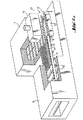
図1は、その中で1枚の板ガラス2がローラコンベア3に沿って移動する炉1を示されている。炉1内で費やされる時間の間、板ガラス2は、その軟化温度に上げられる。板ガラス2はその後、コンベア3によって支持されたまま、型押しステーション4へ導かれる。型押しステーション4には、ローラコンベア3によって定義される平面の下にフレーム5がある。板ガラス2が、このフレームの上方に至ったとき、前記板ガラスが精密に配置されることを、図に示されてはいない部材が可能とし、型押しゾーンにおいてローラをストップさせることによりその移動が停止される。型押しフレーム5は、板ガラスを上昇させるためにローラ3のベッドを上方に通過する。先に述べたように、型押しフレーム5は、前記板ガラスに所定の形状を有し、ローラ3のベッドを通過し得るように設計されている。すなわち、フレーム5が停止されるか、または、例えば、水撃ポンプタイプのシステムを用いて、フレーム5が低い位置から高い位置へ通ることを可能とするように型押しゾーンにおけるローラが設計されている。そのような実施の形態は、当業者には知られている。板ガラス2をピックアップした、型押しフレーム5は、それを、該フレーム5の上方に配置され、有利なことに中実固体である、押し型6に対して押圧する。
【0048】
自動車の外側部品を装備しようと意図される一枚の板ガラス2の場合には、板ガラス2がローラコンベア3上で移動する方向は、人が顔を向けて自動車を見たとして、その人の見ている角度にかかわらず、コンベア3のローラによって残されているかもしれない、いかなる痕も見えないことが要求される。先に説明されたように、前記板ガラスが自動車上の適切な場所にあるときに、板ガラス2上で鉛直方向を有するかもしれない痕が見えないようにする必要である。このことは、前記板ガラスが自動車上に搭載されている場合、コンベア3のローラの回転の軸は、板ガラス2の水平方向に対応する必要があることを意味している。
【0049】
さらに、板ガラス2に与えられる必要がある主たる湾曲は、前記板ガラスが自動車上に存在するときに、前記板ガラスの鉛直方向に配向される。このことは、押圧後に板ガラス2に与えられる湾曲の主方向は、コンベア3のローラの配向に対して直角であることを意味している。板ガラス2を押圧後にこのコンベア3上に戻し載置することが必要ならば、前記コンベア3は、前記板ガラス2の形状を維持し且つ破損させないために十分に安全な受け入れ位置になく、前記板ガラス2は、その中央部によってのみ支持されることになる。すなわち、そのような位置では、完全に支持されておらず且つ依然として高温度のままである板ガラス2がさらに変形するか、または倒れて、前記コンベアのローラに接した状態で破損に導く可能性がある。
【0050】
図2aから図6aに特に詳細に記述された本発明の技術は、これらの危険を防止し且つ型押しステーションにおいて押圧されている間に板ガラス2上に既に与えられた所望の形状を維持することを可能とする。本発明は、ローラの凹面形状が、板ガラスの主たる湾曲形状を支持するように、設計された配置構成の成形されたローラを備えるシャトル上に前記板ガラスを受け入れることにある。
【0051】
図2aは、本発明による装置を図示しており、板ガラス2が、成形されたローラ8を備えているシャトル7に、押圧後に載置され、その後、炉11を通過し且つ板ガラス2を型押しステーション12へ導く運搬用のコンベア10に垂直の通路内に配置される冷却ステーション9へ導かれる。シャトル7およびその成形されたローラ8は、図2bによりわかりやすく図示されている。本発明の動作の原理は、板ガラス2が型押しステーション12へ到達したときに、上側の型14に対して押圧する型押しフレーム13上にピックアップすることにある。図に示されていない、吸引手段はその後、型押しフレーム13がその下部位置に戻り降下し且つシャトル7がコンベア10と上側の型14の間に挿入されている間、前記上側の型に接触させて前記板ガラスを保持する。前記吸引手段はその後、停止され且つ前記板ガラスは、シャトル7の成形されたローラ8によって受け入れられる。オプションとして、吹き出し手段が、板ガラスを下方に載置するのを助けるために設けられていてもよい。上側の型14が前記板ガラスをシャトル7上に投下する前に、上側の型14の下方への鉛直移動が、想定されても良い。シャトル7はそれから、冷却ステーション9へ移動され、板ガラス2は、シャトル7から前記冷却ステーション9を通過する冷却コンベア15へ移送される。移送は、成形されたローラ8を回転することによって行なわれ、当業者に知られているいずれの手段を用いてもよいが、ここには図示されていない。さらに、成形されたローラ8を回転させるこれらの手段は、前記板ガラスが静止したままとなることを防止して、前記ガラスがローラ8によって痕が付されることのいかなる危険をも防止するため、板ガラス2がシャトル7上に載置されるとすぐに、作動しても良い。シャトル7が冷却ステーション9へ移動される間に、シャトル7上で往復移動を得るためにローラ8の交互回転を想定することも可能である。シャトル7の移動は、冷却ステーション9へ入るまでであっても良く、または代替的に、シャトル7が前記冷却ステーションに入って、例えば、板ガラス2が完全に設定されるときには、前記板ガラスがコンベア15へ移送されても良い。
【0052】
当然、図2aにおいて与えられる図は、対称的に例示されても良く、すなわち冷却ステーション9が運搬用のコンベア10の左方に配置されることもできる。本発明は、一つが左、一つが右にある2つの冷却ステーション7が2つのシャトル7と関連付けられる可能性も想定している。
【0053】
図3および図4は、本発明の他の例示的な実施の形態を図示しており、これにより、冷却ステーション16が、炉17、型押しステーション18および炉17を通過し且つ板ガラス2を型押しステーション18へ移送するコンベア19と一直線に据え付けられる。ツーリングの動作の原理は、図2aの実施の形態と同一であるが、本質的な相違は、板ガラスが上側の型20に接触したままで且つ前記上側の型20および下側のフレーム21の間で押圧された直後に90°の角度にわたって板ガラスを回転させることにある。板ガラスは、支持軸22のまわりで上側の型を回転させることにより回転し、この回転は矢印23によって図示されている。前記板ガラスは、図2aの場合と同様に、成形されたローラ25を具備するシャトル24上に戻し載置される。シャトル24はそれから冷却ステーション16へ移動し、板ガラス2は、冷却コンベア26へ移送される。それゆえ、図3は、上側の型20が押圧位置にあるときのこの実施の形態を図示しており、図4は、上側の型20が90°の角度にわたって回転している同一の実施の形態を図示している。
【0054】
図5は、最後の例示的な実施の形態であり、この図に示されていない、3つの冷却ステーションに関連付けられた3つのシャトル27、28、29が存在する。3つのシャトルは、それらのうちの2つ、27および28は、図2aに図示されたように板ガラスを横へ移送することを可能とし、第3の29は、板ガラスが、図3および図4に図示されたようにコンベア30、炉31および型押しステーション32に一直線に、移送されることを可能としている。シャトル29は、当然のことながら、矢印35により示される90°の回転を可能とする軸34と関連付けられる上側の押し型33と共に作動する。
【0055】
この図5において与えられている図は、特に、製造率を最適化することを可能としており、シャトルが移動に費やす時間のために製造率が制限されることは、もはやない。
【0056】
図6aおよび図6bは、成形されたローラ37を搭載するシャトル36が、待機ステーション38と型押しステーション39の間で移動可能である本発明の他の実施の形態を図示している。先に述べた通り、炉40からのそしてローラ41のベッドによって運搬される前記板ガラスが、2つの型42、43を用いて型押しされる型押しステーション39へ運搬される。前記板ガラスはその後、シャトル36の成形されたローラ37上に戻り配置される。板ガラスが前記成形されたローラ37に接触するとすぐに、これらは、板ガラスを冷却ステーション44または45へ駆動するための、図に示されていない、装置によって回転状態に設定される。前記板ガラスは、このように、成形されたローラ37から、成形された、ローラ46または47へ移送される。これらの成形されたローラ46は、冷却ステーション44を通るコンベアを、47は、冷却ステーション45を通るコンベヤを構成する。型押しされた板ガラスは、このようにして、好ましくは冷却ステーション44および45へ、交互に移される。
【0057】
それゆえ、図6aおよび図6bによって図示された本発明による装置のこの実施の形態は、型押しステーション39と待機ステーション38の間で移動するシャトル36を用いることにある。図6bは、型押しステーション39に、板ガラスを、冷却ステーション44、45のうちのいずれかに移動するための位置に配置されたシャトル36を図示している。図6bは、待機ステーションにあり、板ガラスを型押しする動作中のシャトル36を図示している。
【0058】
図6aおよび図6bにこのように示された装置は、図2aから図5によって図示された本発明の代替的な形態の場合と同様に、その構成が、板ガラスの主たる湾曲された形状をローラの凹面形状が支持するように設計され、成形されたローラを備えるシャトル上の板ガラスを受け入れることを可能とする。
【0059】
さらに、本発明の実施の形態にかかわらず、これらのシャトルの移動、そして恐らくさらに、上側の型の移動、前記上側の型に対して板ガラスを保持する吸引装置のトリガー操作並びに前記シャトルの前記成形されたローラの回転は、板ガラスの型押しおよび冷却の間の全ての他のステップと同様に自動化されても良い。
【図面の簡単な説明】
【図1】図1は、本発明に関連する技術を説明する型押しおよび冷却ラインの概略図である。
【図2a】図2aは、本発明による装置の第1の実施の形態の図である。
【図2b】図2bは、本発明による装置の第1の実施の形態の図である。
【図3】図3は、本発明による第2の実施の形態の図である。
【図4】図4は、押圧ステップ後における図3に示された前記第2の実施の形態の図である。
【図5】図5は、本発明による第3の実施の形態の図である。
【図6a】図6aは、本発明による第4の実施の形態の図である。
【図6b】図6bは、本発明による第4の実施の形態の図である。[0001]
(Technical field)
The present invention relates to a technique for embossing a sheet of glass followed by a cooling step. The technique according to the invention can be used to emboss a single sheet of glass, especially for strengthening, or to emboss several sheets of glass which are then cooled and combined in pairs to form a laminate glazing. Will be adapted to either.
[0002]
The invention will be described in more detail with respect to, but not limited to, the shape of a glazing for mounting on the outer parts of a motor vehicle.
[0003]
More specifically, the present invention relies on techniques such that the glass sheets are conveyed one by one through a furnace so that the temperature can be raised to a temperature near the softening temperature, and the glass sheets are conveyed on a roller bed. Related to things. As soon as they leave the furnace, the glazings are led to a stamping station where the lower mold lifts the glazing to press against the upper mold to obtain the desired shape. The glazing is returned on the conveyor to be directed to a cooling station, such as a tempering station.
[0004]
(Background technology)
These embossing techniques are described in detail in U.S. Pat. No. 4,872,898. The document specifically describes a technique whereby a sheet of glass is conveyed over a roller conveyor through a tunnel furnace where the temperature is raised to its softening temperature and then guided to a stamping station. At the embossing station, the glazing is lifted off the conveyor by a frame having a predetermined shape to which the glazing is to be provided. The frame is intermittent so that the glazing can first pass through a bed of rollers resting thereon. The frame then lifts the glazing until it presses against the upper mold of a solid solid, the shape of the upper mold being complementary to the shape of the frame and therefore corresponding to the desired shape of the glazing. I do. After pressing, the lower frame descends back down to the height below the roller bed, thus returning the sheet glass and setting it down onto the roller bed. The rollers resume their movement leading the sheet glass to the tempering station.
[0005]
Other documents describe variations on this type of technology. In particular, with regard to the lower frame, more particularly, the arrangement allows it to pass through the roller bed. Other documents describe even further variations in the design of the rollers in a stamping station to always facilitate the passage of the lower frame.
[0006]
Except for the special feature of the lower frame, which passes through a bed of rollers acting as a conveyor, this type of technology is based on the fact that the stamping operation is performed outside the furnace or at least outside the container maintained by temperature. It has been characterized. This type of technology should therefore be considered as a cold technology, the name of which defines the fact that the embossing station is located outside a temperature-maintained container, which means That is, it is easier to control the placement of the embossing tool than with the hot technique, while the embossing method will start cooling the glass sheet as soon as it leaves the furnace, Competition for time, changes in the embossing action or its conditions are therefore tricky and limited.
[0007]
Furthermore, recent developments, especially in the automotive industry, tend to continually increase the demand for glazing of complex shapes, especially with significant curvatures, while at the same time increasing the required optical quality. Moreover, the thickness of the glazing is also getting thinner.
[0008]
For the outer glazing shape for the automotive industry in tools using this technique, the direction of travel of the glass sheet as it passes through the furnace on a roller conveyor is defined by later use studies. In particular, when the glass sheet is in use, it is not desirable for the mark to appear in an essentially vertical direction, and the mark may be left by the rollers as the temperature increases. If such marks are present, they actually become very noticeable from a certain angle, for example to the person facing the car. Therefore, the direction in which the glazing moves is required so that these marks are seen in an essentially horizontal direction and therefore are not actually seen by anyone.
[0009]
The demands of today's manufacturers are also that they give a significant curvature in the vertical direction after the glazing has been mounted on the vehicle. This significant curvature will therefore correspond to the direction of embossing corresponding to the direction of the conveyor in the furnace. Making the glass sheet conveyable after it has been embossed on a roller conveyor is thus elaborate, and these rollers are oriented in the direction of embossing without the risk of breaking or deforming the glass sheet. Vertical, then they will eventually be supported only by their central part. It is also desirable to maintain the shape obtained after pressing and to be unable to exchange between the pressing station and the cooling station, especially for good process repeatability.
[0010]
Solutions for preventing deformation of the glass sheet after passing through the pressing station have already been proposed. EP 0 523 017 describes in detail the use of a shuttle or moving frame having the final shape of the glass sheet to guide the glass sheet from the stamping station to the cooling station. U.S. Pat. No. 4,433,993 also provides a shuttle across the direction of the conveyor past the furnace. These techniques allow the glass sheet to be treated immediately after pressing, so as to maintain the shape obtained and to quickly guide the glass sheet to the cooling zone. These techniques, however, have drawbacks. First of all, the movement of the shuttle entails indexing for each transport operation in order for the glass sheet to be completely received. Furthermore, the sheet glass is supported on its periphery by the frame, so that the cooling is not uniform. This disadvantage is particularly troublesome when the glazing is annealed or semi-tempered to produce laminate glazing, or even tempered. What happens is that in these various cases, problems occur at the edges, leading to weakening of the glazing.
[0011]
Therefore, the inventors have the advantage of being particularly well suited for embossing thin sheet glass, the absence of the visible marks of the technique described above, especially when glazing is used, and Without these drawbacks, he gave himself the task of developing an embossing technique which allows subsequent cooling of the glass sheet without problems, especially in the vicinity of the glass sheet.
[0012]
The object is, according to the invention, a method for embossing a sheet of glass, which comprises heating said sheet of glass and essentially embossing said sheet of glass to a station for embossing it between two molds. Transporting in a horizontal transport path, forming the glass sheet by pressing between the two molds, cooling the glass sheet at an appropriate station, and embossing the glass sheet. Means comprising a shaped roller for receiving said glass sheet after said shaping, said shaped roller being oriented parallel to the direction defined on said glass sheet by the direction conveyed to the embossing station for said glass sheet. Achieved by methods including:
[0013]
According to the invention, after the pressing phase, the glass sheet is self-formed and after pressing and after forming can maintain its shape and avoid undesired additional deformations. It is set back on the roller that will be. To achieve this result, the rollers are oriented parallel to the direction defined on the glass by the direction in which the glass sheet is transported through the embossing station. That is, in the case of an outer glazing for an automobile having a main curvature in the vertical direction when used and moving through the furnace in this vertical direction, the shaped glazing receiving the sheet glass after pressing. The rollers are oriented at right angles to the vertical direction of the glass sheet when the glass sheet is loaded into an automobile.
[0014]
According to a preferred embodiment of the invention, the means comprising the shaped rollers is a shuttle, which can be moved between at least one, advantageously the embossing station and the cooling station.
[0015]
By means of a shuttle, preferably comprising molded rollers, which can be moved between the embossing station and the cooling station, the use of the molded rollers ensures that the upper mold and the glass sheet are removed from the upper mold. It can be easily inserted between the bed of rollers, transported from the furnace to the embossing station.
[0016]
According to a first alternative form of embodiment of the invention, the glazing is conveyed to the cooling station transversely to the direction in which the glazing is conveyed to the embossing station. According to this embodiment, the shaped rollers are therefore arranged in such a way that they form a lateral receiving bed, preferably at right angles to the conveyor which is carried into the embossing station. According to such an embodiment, the present invention may provide a cooling station on each side of the transport conveyor. Such embodiments therefore use, for example, one and the same shuttle, or, for example, two shuttles, each with shaped rollers, to carry the glass sheets alternately from each of the two sides. . This embodiment may particularly enable the production rate to be increased.
[0017]
According to a second alternative of the embodiment according to the invention, the glazing is kept in contact with the upper die after pressing and it rotates over a 90 ° angle to form the embossing station. To the cooling station in the direction of transport to the cooling station. The present invention thus envisages, according to this alternative, the arrangement of the shaped rollers parallel to the rollers of the conveyor for transport from the furnace to the embossing station. Such an arrangement allows for a linear design which inherently has the advantage that it can be changed by simply adding rotating elements to an existing plant.
[0018]
According to a last alternative form of the invention, it is envisaged that the first two alternative forms are combined, i.e. after the sheet glass has been pressed, the sheet glass is transferred to an embossing station and laterally. It is envisioned that the conveyor can be transported to a cooling station in line with the conveyor for transport to at least one cooling station located. The glazing is then advantageously transported to the respective cooling station, in particular by an associated shuttle, in order to increase the production rate.
[0019]
One advantageous embodiment of the invention envisages that the glass sheet can be moved on a shuttle with the shaped rollers. Such an embodiment also limits the danger of leaving a mark on the glass and also makes it possible for the glass sheet not to remain stationary on the shaped rollers. What happens at this stage of the method is that the glazing, if left stationary on the roller, remains hot enough to leave a mark. Such marks are not oriented in a direction that is clearly bothersome to the viewer, but it is nevertheless desirable to prevent the appearance of such marks in order to achieve better optical quality.
[0020]
With regard to the movement of the shuttle or, more precisely, the means for mounting the shaped rollers, the invention envisages two possibilities. That is, in the first embodiment, the shuttle moves from the stamping station to the entrance of the cooling station to set the glass sheet down on another conveyor, for example, a roller conveyor. In a second embodiment that is particularly suited for some cooling stations, the shuttle enters the cooling station and supports the glazing during at least part of the cooling time. That is, the set sheet glass is picked up by a conveyor, for example, a roller conveyor, and the rollers thereof need not necessarily be formed. In both cases, the passage from the shuttle to the cooling station conveyor occurs naturally by driving the shaped rollers of the shuttle that guide the glass sheet to the cooling station conveyor.
[0021]
In a preferred embodiment of the present invention, it is envisioned that the glazing will reciprocate on the shuttle. This embodiment may in particular have a shuttle of limited length to allow the glass sheet not to remain stationary until it is transferred onto a conveyor of the cooling station.
[0022]
According to another type of embodiment of the invention, the means with shaped rollers is advantageously at least one shuttle that can move between the embossing station and the waiting station. .
[0023]
An advantageous embodiment of this embodiment is characterized in that the shaped rollers mounted on the shuttle move the embossed glass sheet at least transversely to the direction in which the glass sheet is transported to the embossing station. The transfer to one cooling station is assumed.
[0024]
Such an embodiment of the present invention uses a removable shuttle, for example, once the glass sheet has been embossed, resulting from a standby position below an upper mold that may hold the glass sheet, for example. In particular, the glass sheet is set back on the shuttle back down. The shaped rollers operate to transfer the glass sheet to a cooling station provided in a lateral direction. As soon as the sheet glass has left the formed rollers of the shuttle, it is advantageously taken up by a conveyor passing through the cooling station, said conveyor comprising for example formed rollers. In an advantageous alternative form of the invention, two cooling stations are provided laterally, one on each side in the direction in which the sheet glass is transferred to said embossing station. Such a configuration makes it possible to increase the production rate. That is, advantageously, the glass sheets are alternately transferred from one cooling station to another. To this end, the formed rollers operate alternately from one direction of rotation to the other. It is also advantageous to be able to change the cycle so that, for example, if one cooling station has an incident, all sheets can be transferred at least temporarily to only one cooling station. is assumed.
[0025]
The embodiments detailed above require a parking position or station for the transfer shuttle during the stamping operation of the glazing. According to the configuration described above, this stand-by position is advantageously provided in alignment with the conveyor for the furnace, i.e. in line with the direction in which the sheet glass is conveyed to the stamping station. I have.
[0026]
According to the invention, the standby position of such a mobile shuttle is provided transversely to the direction in which the glass sheet is transported to the embossing station, and the cooling station is arranged so that the glass sheet is transported to the embossing station. Alternative embodiments of the embodiments provided that are aligned with the furnace conveyor in the same direction as the above, and are therefore also envisioned. According to this embodiment, the glazing rotates through a 90 ° angle before placing on the mobile shuttle.
[0027]
The invention also proposes a device for implementing the method described above. This embossing device according to the invention is a device for heating and heating a sheet of glass and an apparatus for supporting and transporting said sheet glass essentially in a horizontal plane through said furnace to an embossing station comprising two pressing dies. Wherein the lower mold passes through the transport device to press the glass sheet against the upper mold, the apparatus comprising a device comprising means for holding the glass sheet after being formed. The embossing device also comprises at least one cooling station and at least one shuttle with shaped rollers for receiving the sheet glass after pressing, the shuttle between the embossing station and the other stations. The shaped roller may move in a direction parallel to a defined direction on the glass sheet via a direction conveyed to the embossing station. It is directed.
[0028]
The device for supporting and transporting the sheet glass is advantageously a roller conveyor, which may terminate in an air cushion system at a stamping station.
[0029]
The embossing device thus described, after the step of pressing a sheet of glass, provides a shuttle with shaped rollers to receive the embossed glass and maintain its shape to the cooling station. , Allowing the glass sheet to remain in contact with the upper mold to bring it to the stamping station.
[0030]
The first embodiment of the device according to the invention advantageously envisages a shuttle that can be moved between an embossing station and a cooling station.
[0031]
According to a first alternative of this embodiment of the invention, the direction of travel of the shuttle is transverse to the direction in which the glass sheets are transported from the furnace to the embossing station. According to this embodiment, the formed rollers are arranged, for example, in a direction perpendicular to the rollers of a conveyor that transports the sheet glass from a heating furnace.
[0032]
According to a second alternative form of this embodiment of the invention, the direction of travel of the shuttle is an extension of the direction in which the glass sheet is transported from the furnace to the stamping station, and Pivots over a 90 ° angle after being pressed. Such an alternative embodiment, therefore, is characterized in that, after pressing, while the glass sheet is held in contact with the upper mold, the stamped glass sheet is placed on the upper mold by means of the shuttle. In order to be able to be placed back on the shaped rollers, a swiveling is to take place, said rollers being parallel to the rollers of the conveyor for transport from the furnace.
[0033]
The preferred embodiment of the present invention according to this first embodiment assumes that the shaped roller of the shuttle is a driven roller. That is, this embodiment allows the glazing to be set into operation as soon as it is placed on the shuttle.
[0034]
Preferably, the shaped rollers provide an alternating rotational movement to allow the glass sheet to reciprocate on the shuttle, especially to allow this when the glass sheet is moving. You may have.
[0035]
In an alternative form of the invention, the shuttle enters the cooling station. The alternating rotation of the shaped rollers is then particularly advantageous.
[0036]
A second embodiment of the device according to the invention advantageously envisages a shuttle that can be moved between the embossing station and the waiting station.
[0037]
According to this second embodiment of the invention, the shaped roller is a roller driven in at least one direction of rotation.
[0038]
Therefore, this second embodiment of the device according to the invention essentially consists in a shuttle that can move between a waiting station and said embossing station, said shuttle comprising: In order to move the sheet glass to a cooling station, the sheet glass is provided with a shaped roller which is set in a rotating state as soon as it is placed. The shaped rollers mounted on the shuttle are located below the upper mold, advantageously in the extension of a conveyor with shaped rollers passing through the cooling station. The glass sheet is thus transferred without stopping from the formed rollers of the shuttle to the formed rollers of the conveyor.
[0039]
With regard to the upper mold, suction means are advantageously provided to hold the glass sheet after pressing. In particular, it is also possible to envisage blowing means for facilitating the mounting of the sheet glass on the shuttle. Such blowing means are of course not used until the suction means is no longer used. The present invention relates to a method of manufacturing a vehicle, comprising: moving the upper mold downward so as to approach the shuttle, particularly in order to reduce the time required for placement on the shuttle; It is also assumed that it is possible to move to. Such an embodiment reduces the risk of breaking the glazing, the glazing being dropped onto the shuttle from a very low point.
[0040]
According to the present invention, the apparatus and method thus described make it possible to emboss a glazing using the cold technology described above, and at the same time, at the same time, be used as outer glazing in a motor vehicle. It enables a high degree of molding accuracy and high optical quality of the glazing intended to be used.
[0041]
The apparatus and the method according to the invention are such that, in effect, after the glass sheet has been pressed onto the shaped rollers of the shuttle, it receives the glass sheet and thus maintains the desired shape very precisely and once the glass is When mounted on a vehicle, it makes it possible to avoid visible marks. Such sheet glass would be used as a monolithic glazing or in combination two by two to form a laminate glazing.
[0042]
Furthermore, in order to optimize the production rate, the invention advantageously proposes an apparatus with several cooling stations.
[0043]
In the case of the first apparatus according to the invention, i.e. in the case of a shuttle movable between the embossing station and the cooling station, the invention provides an extension of the direction of the apparatus for transporting the glass sheet from the furnace to the embossing station. And / or at least one cooling station oriented transversely to the above-mentioned directions. According to a preferred embodiment of the present invention, there are three cooling stations, each associated with one shuttle, wherein the upper die is rotated about an axis to allow it to rotate through 90 °. It is specifically envisaged that it would be possible to move with.
[0044]
In the case of the second device according to the invention, i.e. in the case of a shuttle movable between the embossing station and the standby station, the invention provides for a side on either side of the direction in which the glass sheet is transported to the embossing station. Advantageously, two cooling stations arranged side by side are provided. According to this embodiment, it is necessary to provide two cooling stations in a single moving shuttle, said rollers being driven for rotational movement in one direction or the other, preferably alternately, Two successive embossed glazings are alternately moved to the two cooling stations.
[0045]
(Best Mode for Carrying Out the Invention)
Other advantageous features and details of the present invention will become apparent in the following from the description of some exemplary embodiments of the invention given with reference to FIGS.
[0046]
The various figures have not been drawn to scale for clarity.
[0047]
FIG. 1 shows a furnace 1 in which one sheet glass 2 moves along a roller conveyor 3. During the time spent in the furnace 1, the glass sheet 2 is raised to its softening temperature. The glass sheet 2 is then guided to the stamping station 4 while being supported by the conveyor 3. In the embossing station 4 there is a frame 5 below the plane defined by the roller conveyor 3. When the sheet glass 2 reaches above the frame, the members not shown enable the sheet glass to be precisely positioned, and the movement is stopped by stopping the rollers in the embossing zone. Is done. The embossing frame 5 passes upward through the bed of rollers 3 to raise the glass sheet. As described above, the embossing frame 5 has a predetermined shape in the sheet glass and is designed to be able to pass through the bed of the rollers 3. That is, the frame 5 is stopped or the rollers in the embossing zone are designed to allow the frame 5 to pass from a lower position to a higher position, for example using a water hammer pump type system. I have. Such embodiments are known to those skilled in the art. The embossing frame 5, which has picked up the glazing 2, presses it against a pressing mold 6, which is arranged above the frame 5 and which is advantageously a solid solid.
[0048]
In the case of a single sheet of glass 2 intended to be equipped with the outer parts of a car, the direction in which the sheet of glass 2 moves on the roller conveyor 3 is that of a person looking at the car with his / her head facing. Regardless of the angle at which it is, it is required that no marks be visible which may be left by the rollers of the conveyor 3. As explained above, it is necessary to ensure that when the glazing is in place on the motor vehicle, there is no visible mark on the glazing 2 that may have a vertical orientation. This means that when the glass sheet is mounted on an automobile, the axis of rotation of the rollers of the conveyor 3 must correspond to the horizontal direction of the glass sheet 2.
[0049]
Furthermore, the main curvature that needs to be imparted to the glass sheet 2 is oriented in the vertical direction of the glass sheet when the glass sheet is present on an automobile. This means that the main direction of the curvature given to the glass sheet 2 after pressing is perpendicular to the orientation of the rollers of the conveyor 3. If it is necessary to place the sheet glass 2 back on this conveyor 3 after pressing, the conveyor 3 is not in a receiving position that is sufficiently secure to maintain the shape of the sheet glass 2 and not to break it, Will be supported only by its center. In other words, in such a position, the glass sheet 2 that is not completely supported and still remains at a high temperature may be further deformed or fall down, leading to breakage in contact with the rollers of the conveyor. is there.
[0050]
The technique of the present invention, which is described in greater detail in FIGS. 2a to 6a, avoids these dangers and maintains the desired shape already provided on the glass sheet 2 while being pressed at the stamping station. Is possible. The invention consists in receiving said glass sheet on a shuttle comprising shaped rollers in an arrangement designed such that the concave shape of the roller supports the main curved shape of the glass sheet.
[0051]
FIG. 2 a shows an apparatus according to the invention, in which the glass sheet 2 is placed after pressing on a shuttle 7 equipped with shaped rollers 8, and then passes through a furnace 11 and stamps the glass sheet 2. It is led to a cooling station 9 which is arranged in a path perpendicular to the transport conveyor 10 leading to the station 12. The shuttle 7 and its shaped roller 8 are better illustrated in FIG. 2b. The principle of operation of the present invention is that when the glass sheet 2 reaches the embossing station 12, it is picked up on the embossing frame 13 which presses against the upper mold 14. The suction means, not shown in the figure, then contact the upper mold while the embossing frame 13 is lowered back to its lower position and the shuttle 7 is inserted between the conveyor 10 and the upper mold 14. Then, the plate glass is held. The suction means is then stopped and the glazing is received by the shaped rollers 8 of the shuttle 7. Optionally, blowing means may be provided to help place the glass sheet down. Before the upper mold 14 drops the glass sheet onto the shuttle 7, a downward vertical movement of the upper mold 14 may be envisaged. The shuttle 7 is then moved to a cooling station 9 and the glass sheets 2 are transferred from the shuttle 7 to a cooling conveyor 15 passing through said cooling station 9. The transfer is performed by rotating the formed roller 8, and any means known to those skilled in the art may be used, but is not shown here. In addition, these means of rotating the formed roller 8 prevent the glass sheet from remaining stationary and prevent any danger of the glass being scored by the roller 8, It may be activated as soon as the glass sheet 2 is placed on the shuttle 7. While the shuttle 7 is being moved to the cooling station 9, it is also possible to envisage alternating rotation of the rollers 8 in order to obtain a reciprocating movement on the shuttle 7. The movement of the shuttle 7 may be until it enters the cooling station 9 or, alternatively, when the shuttle 7 enters the cooling station and, for example, the sheet glass 2 is fully set, the sheet glass is transferred to the conveyor 15. May be transferred to
[0052]
Of course, the diagram given in FIG. 2a may be illustrated symmetrically, ie the cooling station 9 can also be arranged to the left of the conveyor 10 for transport. The invention also envisages the possibility that two cooling stations 7, one on the left and one on the right, are associated with two shuttles 7.
[0053]
FIGS. 3 and 4 illustrate another exemplary embodiment of the present invention whereby the cooling station 16 passes through a furnace 17, an embossing station 18 and a furnace 17 and molds the glass sheet 2. It is installed in line with a conveyor 19 that transfers to a pushing station 18. The principle of operation of the tooling is the same as in the embodiment of FIG. 2 a, but the essential difference is that the glass sheet remains in contact with the upper mold 20 and between the upper mold 20 and the lower frame 21. Is to rotate the sheet glass over a 90 ° angle immediately after being pressed. The glazing is rotated by rotating the upper mold about a support shaft 22, this rotation being illustrated by arrow 23. The sheet glass is placed back on a shuttle 24 with shaped rollers 25, as in FIG. 2a. The shuttle 24 then moves to the cooling station 16 and the glass sheet 2 is transferred to the cooling conveyor 26. Therefore, FIG. 3 illustrates this embodiment when the upper mold 20 is in the pressed position, and FIG. 4 illustrates the same embodiment where the upper mold 20 is rotated through a 90 ° angle. FIG.
[0054]
FIG. 5 is the last exemplary embodiment, and there are three shuttles 27, 28, 29 associated with three cooling stations, not shown in this figure. The three shuttles allow two of them, 27 and 28, to transfer the glass sheet laterally as illustrated in FIG. As shown in the drawing, it can be transferred straight to the conveyor 30, the furnace 31 and the embossing station 32. The shuttle 29 operates, of course, with an upper die 33 associated with a shaft 34 that allows a 90 ° rotation indicated by arrow 35.
[0055]
The diagram given in this FIG. 5 makes it possible, in particular, to optimize the production rate, and the production rate is no longer limited by the time the shuttle spends moving.
[0056]
FIGS. 6a and 6b illustrate another embodiment of the present invention in which a shuttle 36 carrying a shaped roller 37 is movable between a waiting station 38 and a stamping station 39. FIG. As previously mentioned, the glazing from the furnace 40 and conveyed by the bed of rollers 41 is conveyed to an embossing station 39 which is embossed using two dies 42,43. The glazing is then placed back on the formed rollers 37 of the shuttle 36. As soon as the glass sheets contact the shaped rollers 37, they are set in a rotating state by a device, not shown, for driving the glass sheets to the cooling station 44 or 45. The sheet glass is thus transferred from the formed roller 37 to the formed roller 46 or 47. These formed rollers 46 constitute a conveyor passing through the cooling station 44, and 47 constitutes a conveyor passing through the cooling station 45. The embossed glazing is thus alternately transferred, preferably to cooling stations 44 and 45.
[0057]
Therefore, this embodiment of the device according to the invention illustrated by FIGS. 6 a and 6 b consists in using a shuttle 36 that moves between an embossing station 39 and a waiting station 38. FIG. 6 b illustrates the shuttle 36 positioned at the embossing station 39 for moving the glazing to one of the cooling stations 44, 45. FIG. 6b illustrates the shuttle 36 at the waiting station and in operation for stamping the glazing.
[0058]
The device thus shown in FIGS. 6a and 6b, as in the case of the alternative embodiment of the invention illustrated by FIGS. 2a to 5, has a configuration in which the main curved shape of the glazing is rolled. The concave shape of the support is designed to support and allow receiving a glass sheet on a shuttle with molded rollers.
[0059]
Furthermore, regardless of the embodiment of the invention, the movement of these shuttles, and possibly also the movement of the upper mold, the triggering of the suction device holding the glass sheet with respect to the upper mold and the shaping of the shuttle The rotation of the applied rollers may be automated, as can all other steps during embossing and cooling of the glass sheet.
[Brief description of the drawings]
FIG. 1 is a schematic diagram of an embossing and cooling line illustrating a technique related to the present invention.
FIG. 2a is a diagram of a first embodiment of the device according to the invention.
FIG. 2b is a diagram of a first embodiment of the device according to the invention.
FIG. 3 is a diagram of a second embodiment according to the present invention.
FIG. 4 is a view of the second embodiment shown in FIG. 3 after a pressing step.
FIG. 5 is a diagram of a third embodiment according to the present invention.
FIG. 6a is a diagram of a fourth embodiment according to the present invention.
FIG. 6b is a diagram of a fourth embodiment according to the present invention.