JP2004363660A - Receiver and reception method - Google Patents
Receiver and reception method Download PDFInfo
- Publication number
- JP2004363660A JP2004363660A JP2003156125A JP2003156125A JP2004363660A JP 2004363660 A JP2004363660 A JP 2004363660A JP 2003156125 A JP2003156125 A JP 2003156125A JP 2003156125 A JP2003156125 A JP 2003156125A JP 2004363660 A JP2004363660 A JP 2004363660A
- Authority
- JP
- Japan
- Prior art keywords
- channel
- frequency
- allocation pattern
- signal
- frequency allocation
- Prior art date
- Legal status (The legal status is an assumption and is not a legal conclusion. Google has not performed a legal analysis and makes no representation as to the accuracy of the status listed.)
- Pending
Links
Images

Classifications
-
- H—ELECTRICITY
- H04—ELECTRIC COMMUNICATION TECHNIQUE
- H04H—BROADCAST COMMUNICATION
- H04H40/00—Arrangements specially adapted for receiving broadcast information
- H04H40/18—Arrangements characterised by circuits or components specially adapted for receiving
-
- H—ELECTRICITY
- H04—ELECTRIC COMMUNICATION TECHNIQUE
- H04H—BROADCAST COMMUNICATION
- H04H20/00—Arrangements for broadcast or for distribution combined with broadcast
- H04H20/65—Arrangements characterised by transmission systems for broadcast
- H04H20/76—Wired systems
- H04H20/77—Wired systems using carrier waves
- H04H20/78—CATV [Community Antenna Television] systems
-
- H—ELECTRICITY
- H04—ELECTRIC COMMUNICATION TECHNIQUE
- H04N—PICTORIAL COMMUNICATION, e.g. TELEVISION
- H04N21/00—Selective content distribution, e.g. interactive television or video on demand [VOD]
- H04N21/40—Client devices specifically adapted for the reception of or interaction with content, e.g. set-top-box [STB]; Operations thereof
- H04N21/41—Structure of client; Structure of client peripherals
- H04N21/426—Internal components of the client ; Characteristics thereof
-
- H—ELECTRICITY
- H04—ELECTRIC COMMUNICATION TECHNIQUE
- H04N—PICTORIAL COMMUNICATION, e.g. TELEVISION
- H04N21/00—Selective content distribution, e.g. interactive television or video on demand [VOD]
- H04N21/40—Client devices specifically adapted for the reception of or interaction with content, e.g. set-top-box [STB]; Operations thereof
- H04N21/43—Processing of content or additional data, e.g. demultiplexing additional data from a digital video stream; Elementary client operations, e.g. monitoring of home network or synchronising decoder's clock; Client middleware
- H04N21/434—Disassembling of a multiplex stream, e.g. demultiplexing audio and video streams, extraction of additional data from a video stream; Remultiplexing of multiplex streams; Extraction or processing of SI; Disassembling of packetised elementary stream
- H04N21/4345—Extraction or processing of SI, e.g. extracting service information from an MPEG stream
-
- H—ELECTRICITY
- H04—ELECTRIC COMMUNICATION TECHNIQUE
- H04N—PICTORIAL COMMUNICATION, e.g. TELEVISION
- H04N21/00—Selective content distribution, e.g. interactive television or video on demand [VOD]
- H04N21/40—Client devices specifically adapted for the reception of or interaction with content, e.g. set-top-box [STB]; Operations thereof
- H04N21/43—Processing of content or additional data, e.g. demultiplexing additional data from a digital video stream; Elementary client operations, e.g. monitoring of home network or synchronising decoder's clock; Client middleware
- H04N21/438—Interfacing the downstream path of the transmission network originating from a server, e.g. retrieving MPEG packets from an IP network
- H04N21/4383—Accessing a communication channel
-
- H—ELECTRICITY
- H04—ELECTRIC COMMUNICATION TECHNIQUE
- H04N—PICTORIAL COMMUNICATION, e.g. TELEVISION
- H04N21/00—Selective content distribution, e.g. interactive television or video on demand [VOD]
- H04N21/40—Client devices specifically adapted for the reception of or interaction with content, e.g. set-top-box [STB]; Operations thereof
- H04N21/43—Processing of content or additional data, e.g. demultiplexing additional data from a digital video stream; Elementary client operations, e.g. monitoring of home network or synchronising decoder's clock; Client middleware
- H04N21/443—OS processes, e.g. booting an STB, implementing a Java virtual machine in an STB or power management in an STB
- H04N21/4432—Powering on the client, e.g. bootstrap loading using setup parameters being stored locally or received from the server
-
- H—ELECTRICITY
- H04—ELECTRIC COMMUNICATION TECHNIQUE
- H04N—PICTORIAL COMMUNICATION, e.g. TELEVISION
- H04N5/00—Details of television systems
- H04N5/44—Receiver circuitry for the reception of television signals according to analogue transmission standards
- H04N5/50—Tuning indicators; Automatic tuning control
-
- H—ELECTRICITY
- H04—ELECTRIC COMMUNICATION TECHNIQUE
- H04N—PICTORIAL COMMUNICATION, e.g. TELEVISION
- H04N7/00—Television systems
- H04N7/16—Analogue secrecy systems; Analogue subscription systems
Abstract
Description
【0001】
【発明の属する技術分野】
本発明は、デジタル放送の受信に使用される受信装置に関し、特に、デジタル放送チャンネル周波数割当パターンを迅速に判別しチャンネルスキャンを行なう技術に関する。
【0002】
【従来の技術】
米国ケーブルTVシステムにおいては、チャンネル周波数割当パターンがSTD(Standard Frequencies)、IRC(Incremental Related Carriers)、HRC(Harmonic Related Carriers)の3種類あり、いずれかのチャンネル周波数割当パターンを適切に選択しないと受信が不可能となる。そこでSTDで選局を開始し、同期信号及び自動微同調制御信号(Automatic Fine Tuning: AFT)により引き込みを行い、STDからのオフセット周波数を記憶し、そのオフセット値を各チャンネル周波数割当パターンの判定基準となるオフセット値と比較することにより、チャンネル周波数割当パターンの判別を可能としている(例として、特許文献1参照。)。
【0003】
また、有効なデジタル放送チャンネルのチャンネル情報を記憶させる手段として、各チャンネル周波数割当パターンにおいて全チャンネルのスキャンを行うことにより、デジタル放送チャンネルを識別し、識別された各チャンネルのスキップフラグデータを記憶手段に記憶することにより、利用者が有効なチャンネルのみを選局することを可能としている(例えば、特許文献2参照。)。
【0004】
また、ユーザーによる受信可能チャンネル番号の入力により、ディジタル信号によるCATV放送の受信モードを自動判断し、自動チャンネル合わせを実行する技術も開示されている(例えば、特許文献3)。
【0005】
【特許文献1】
特開平10−136278号公報(第7−11頁、第1図)
【特許文献2】
特開2000−59180号公報(第5−8頁、第1図)
【特許文献3】
特開2001−339651号公報(第2−5頁、第2、3図)
【0006】
【発明が解決しようとする課題】
アナログ放送受信装置ならびにデジタル放送受信装置は、受信可能なチャンネルに関する情報をチャンネルリストデータとして、例えば不揮発性記憶手段に格納している。受信装置の電源が最初に投入された時点では、このチャンネルリストデータにはチャンネル情報が含まれていない。したがって、受信装置の利用者が、例えば昇順にチャンネルを変更する命令などを出した場合に、各チャンネルの放送信号の有無に関わらず、全てのチャンネルを昇順に選択してしまうため、すばやい選局動作が困難となる。そこで、なんらかの手段により受信可能なチャンネルのチャンネル情報を格納する必要がある。
【0007】
そこで、米国ケーブルTVシステムにおいてデジタル変調方式で変調されたデジタル放送が伝送される場合において、あらかじめ各チャンネル周波数割当パターンでの全チャンネルのデジタル放送チャンネルを識別し、仮想チャンネル番号およびプログラム番号などを含む有効なデジタル放送チャンネルのチャンネルリストを作成しておくことによって、短時間での選局動作が可能となる。しかしながら、米国ケーブル放送においては、チャンネル数が100以上と多いことに加え、チャンネルスキャン時にチャンネル情報を取得するためには、まずどのチャンネル周波数割当パターンが使用されているかを判別する必要がある。そのため1つのチャンネルにおいてチャンネル周波数割当パターン毎にスキャンを行うため、多くの時間を要する。さらに米国のケーブルデジタル放送は一般的に550MHz以上の周波数帯域に配置される為、1チャンネルからチャンネルスキャンを開始した場合、チャンネル80付近のデジタル放送信号を受信するまでの間、3つのチャンネル周波数割当パターンでスキャンを行ったところでどのチャンネル周波数割当パターンであるかを判別することは出来ず、不要なスキャン時間を費やすことになる。また米国のデジタルケーブル放送では、変調方式が64QAM、256QAM、8VSBの3つの方式に対応している。従って、チャンネル周波数割当パターンを特定するまでは、1つの物理チャンネルにおいて、3つのチャンネル周波数割当パターンと3つの変調方式を掛け合わせた合計9通りのスキャンを行う必要があり、チャンネルスキャンの所要時間が膨大になってしまう問題があった。
【0008】
本発明は上記のような問題点を鑑みて考案されたものであり、その目的は、ケーブルテレビ放送受信システムにおいて、チャンネル周波数割当パターンを可能な限り短時間で判別し、チャンネル周波数割当パターンとチャンネルのプログラム情報をチャンネルリストに記憶させる方法およびデジタル放送受信装置を提供することにある。
【0009】
【課題を解決するための手段】
本発明の目的を達成するために、ケーブルテレビ放送でのデジタル放送信号のチャンネル配置が通常550MHz以上であることを踏まえ、チャンネルスキャンを1CHからではなく550MHz以上のチャンネル、例えば80CHからスキャンを開始し、いずれかのチャンネル周波数割当パターンにおいて復調が可能な場合、そのときのチャンネル周波数割当パターンがそのケーブルテレビ放送に適合すると判定し、そのチャンネル周波数割当パターンを記憶する構成とする。このデジタル放送受信装置により、チャンネル周波数割当パターンを従来の方法に比べ短時間で判別することが可能となり、全チャンネルスキャンに要する時間を大幅に短縮することが可能となる。
【0010】
【発明の実施の形態】
本発明に係るデジタル放送受信装置、ここでは、米国のケーブルデジタル放送受信装置について、以下、図面を参照して本発明の実施形態を詳細に説明する。
【0011】
米国でのケーブルデジタル放送における変調方式として64QAM(Quadrature Amplitude Modulation)および256QAMと、地上波デジタル放送を再送信に対応するため、8VSB(Vestigial Side Band)変調方式が採用されている。また現在はNTSC(National Television System Committee)方式のアナログ信号がケーブルテレビ放送用帯域内で混在した環境となる。
【0012】
図2は本発明を適用した実施形態における自動チャンネルスキャン機能を有したデジタル放送受信装置の構成を示すブロック図である。
【0013】
このデジタル放送受信装置では、例えば同軸ケーブルからデジタル放送信号またはアナログ放送信号が受信装置入力1として入力される。受信装置に入力された信号はチューナ2に供給され、入力された信号から所望の物理チャンネルが選局される。ここで物理チャンネルとは、ケーブルテレビ波放送の各チャンネルに割り当てられた周波数を意味する。この選局動作は制御手段6により制御される。選局された信号は増幅手段3によって増幅されるが、増幅の大きさはAGC手段5によって制御される。増幅された信号は復調手段4に供給され、64QAM、256QAM、8VSBいずれかの変調方式で復調される。復調手段4から出力された信号はデマルチプレクサ8に供給される。
【0014】
デマルチプレクサ8に供給された信号は映像データ、音声データなどに分離され、映像データはビデオデコーダ9に供給されると共に、音声データはオーディオデコーダ10に供給される。ビデオデコーダ7では符号化された映像データを復号し、映像信号として出力する。また、オーディオデコーダ10では符号化された音声データを復号し、音声信号として出力する。本発明の受信装置は、表示装置11およびスピーカ12を付属すればテレビジョンセットとして使用できる。即ち、本発明における自動チャンネルスキャンにより作成されるチャンネルリストを表示装置11に表示することができる。さらに、デマルチプレクサ8ではトランスポートストリームに含まれるプログラム情報、例えばVCT(Virtual Channel Table)情報を抽出し、制御手段6に供給する。制御手段6は不揮発性記憶手段7と接続され、必要なデータを記憶することができる。なお、VCT情報はその物理チャンネルに含まれる各プログラムの情報であって、仮想チャンネル番号、変調方式、チャンネルTS−ID(Transport Stream−Identification)、プログラム番号などの情報が含まれる。ここで仮想チャンネル番号とは、放送事業者が各番組に対して付帯する情報であり、例えば物理チャンネル番号を使用したメジャーチャンネル番号と、例えば選局している物理チャンネルに含まれる番組を順番に番号付けしたマイナーチャンネル番号から成る。また、変調方式は米国の場合、64QAMまたは256QAMまたは8VSBである。チャンネルTS−IDは、各MPEG TSに付けられたIDであり、プログラム番号はMPEG TSに含まれるプログラム数を示す。
【0015】
以上のように構成された受信装置において、自動チャンネルスキャン機能を実行する際の動作について図1を用いて説明する。
【0016】
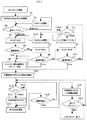
図1は本発明を適用した実施形態において、米国のケーブル放送で規定されているSTD、IRC、HRCそれぞれにおける物理チャンネル配置について、自動チャンネルスキャンを実行する場合の迅速なチャンネル周波数割当決定方法および自動チャンネルスキャン機能を説明するためのフローチャートである。
以下、図1を参照してケーブルデジタル放送を受信する場合の自動チャンネルスキャンの動作を詳細に説明する。まず、ステップS1において制御手段6は、例えば物理チャンネル80を設定し、物理チャンネルを選局するようチューナ2を制御する。米国のケーブル放送の場合、物理チャンネル範囲は1ないし2〜135(但し、米国の規格EIA−542Aでは、チャンネルプランとしては158まであるため、135までという限りではなく、受信機が対応するチャンネル数に依存する)であるが、デジタル放送においては、一般的に550MHz以上を使用しているため、スキャン開始を例えばチャンネル80に設定する。またチャンネル135から降順にスキャンを行うこともスキャンの所要時間を短縮するという目的に合致するが、実際の放送においては現在のところ、135チャンネルまでデジタル放送がなされているわけではないため、いち早くチャンネル周波数割当パターンを判別することが最優先であると考えれば、チャンネル80付近から開始するのが最も望ましい。
【0017】
デジタル放送を有するチャンネル上限のチャンネルはケーブルテレビ放送局によって異なる可能性があるが、ケーブルテレビのチャンネル配置上、チャンネル80〜115(約750MHz)の間にデジタル信号が無い場合は、チャンネル116以上にデジタル信号が存在する可能性が低いと考えられる。従って、いち早くデジタル信号を捕らえるためには、チャンネル80に限られず、例えば、チャンネル80〜115のいずれかのチャンネルを最初のチャンネルとして選局を開始してもよい。
【0018】
一方550MHz以下のチャンネルはアナログ放送に占有されている為、デジタル放送用受信機においてチャンネルスキャンを行った場合、チャンネル1から開始すると、チャンネル周波数割当パターンがSTD、IRC、HRCのいずれかであることを特定するまでに膨大な時間が掛かる。
【0019】
次にステップS2において、選局したチャンネルの信号レベルはAGC手段5によって調整される。もしAGC手段5によって増幅度が最大になっても信号が検知されない場合、このチャンネルには放送信号が存在しないまたは存在してもレベルが小さすぎるために受信不可と判定され、直ちに次のチャンネル選局に移行する。もし選局したチャンネルの信号が受信可能な信号レベルと判定された場合はステップS3に進む。
【0020】
ステップS3において制御手段6は、チャンネル周波数割当パターンをSTDに設定し、チューナ2に選局を行わせる。STDを最初に選択する理由は、STDがケーブル放送で最も多く使用されているからである。
【0021】
ステップS4において制御手段6は復調手段4より復調同期したか否かの情報を判定する。復調同期していない場合、ステップS7において制御手段6がチャンネル周波数割当パターンをIRCに設定し、チューナ2に選局を行わせる。ステップS4同様、ステップS7において制御手段6は復調手段4より復調同期したか否かの情報を判定する。ステップS9において制御手段6がチャンネル周波数割当パターンをHRCに設定し、チューナ2に選局を行わせる。ここでも復調同期していない場合、この物理チャンネルにデジタル放送信号は存在しないと判断し、ステップS11に進む。
【0022】
ステップS11において、制御手段6は現在のチャンネル番号を確認し、チャンネルが135未満であれば、ステップS13において、昇順で次のチャンネルを選局させ、上記ステップS3へと戻る。またステップS11において、チャンネルが135であれば、ステップS12においてチャンネルの値を0に設定し、ステップS13において、昇順で次のチャンネルを選局させ、上記ステップS3へと戻る。
【0023】
ステップS4において復調同期したと判定された場合、ステップS5においてチャンネル周波数割当パターンがSTDであると決定される。以後チャンネルスキャンでは、IRCとHRCは選択しないことになる為、1チャンネル辺りのチャンネルスキャンは1/3に短縮される。またステップS7において復調同期したと判定された場合、チャンネル周波数割当パターンはIRCとして、またステップS9において復調同期したと判定された場合、チャンネル周波数割当パターンはHRCとして、それぞれチャンネル周波数割当パターンがステップS5において決定され、ステップS14において、そのチャンネルのプログラム情報が不揮発性記憶手段7によって格納される。また以後のチャンネルスキャンでは、該当するチャンネル周波数割当パターンのみを選択するため、1チャンネル辺りのチャンネルスキャンは1/3に短縮される。
【0024】
ステップS5におけるチャンネル周波数割当パターン決定後は、残りのチャンネルのスキャンが行われる。ステップS15において、ステップS11同様、制御手段6は現在のチャンネル番号を確認し、チャンネルが135未満であれば、ステップS17において、昇順で次のチャンネルを選局させ、ステップS18に進む。チャンネルが135であれば、ステップS16においてチャンネルの値を0に設定し、ステップS17において、昇順で次のチャンネルを選局させ、ステップS18へ進む。
【0025】
ステップS18において復調同期していないと判定された場合、ステップS15に戻る。復調同期したと判定された場合、ステップ19において、そのチャンネルのプログラム情報が不揮発性記憶手段7によって格納される。
【0026】
その後ステップS20において全物理チャンネルについてスキャンが終了したか否かを判定する。未完の場合はステップS15に戻り、全チャンネルのスキャンが終了するまで、S15からS20までを繰り返す。終了している場合はチャンネルスキャンを終了する。
【0027】
上記ステップにより、全チャンネルスキャンによるチャンネルリスト作成の時間を大幅に短縮することができる。
【0028】
【発明の効果】
上記発明により、ユーザーにとって使い勝手の良い受信装置の提供が可能となる。
【図面の簡単な説明】
【図1】本発明を適用した実施形態におけるチャンネル周波数割当決定機能および自動チャンネルスキャン機能を説明するためのフローチャートである。
【図2】本発明を適用した実施形態におけるチャンネル周波数割当決定機能および自動チャンネルスキャン機能を有したデジタル放送受信装置の構成を示すブロック図である。
【符号の説明】
1 受信装置入力
2 チューナ
3 増幅手段
4 復調手段
5 AGC手段
6 制御手段
7 不揮発性記憶手段
8 デマルチプレクサ
9 ビデオデコーダ
10 オーディオデコーダ
11 表示装置
12 スピーカ[0001]
TECHNICAL FIELD OF THE INVENTION
The present invention relates to a receiving apparatus used for receiving a digital broadcast, and more particularly to a technique for quickly determining a digital broadcast channel frequency allocation pattern and performing a channel scan.
[0002]
[Prior art]
In the U.S. cable TV system, there are three types of channel frequency allocation patterns: STD (Standard Frequency), IRC (Incremental Related Carriers), and HRC (Harmonic Related Carriers), and reception is performed unless one of the channel frequency allocation patterns is properly selected. Becomes impossible. Therefore, channel selection is started by STD, pull-in is performed by a synchronization signal and an automatic fine tuning control signal (Automatic Fine Tuning: AFT), an offset frequency from the STD is stored, and the offset value is used as a criterion for determining each channel frequency allocation pattern. By comparing the channel frequency allocation pattern with the offset value (see, for example, Patent Document 1).
[0003]
Also, as means for storing channel information of valid digital broadcast channels, all channels are scanned in each channel frequency allocation pattern to identify digital broadcast channels and store skip flag data of each identified channel. , It is possible for the user to select only valid channels (for example, see Patent Document 2).
[0004]
Further, there is disclosed a technique of automatically determining a reception mode of a CATV broadcast by a digital signal based on input of a receivable channel number by a user and executing automatic channel tuning (for example, Patent Document 3).
[0005]
[Patent Document 1]
JP-A-10-136278 (pages 7-11, FIG. 1)
[Patent Document 2]
JP-A-2000-59180 (pages 5-8, FIG. 1)
[Patent Document 3]
JP 2001-339651 A (Pages 2-5, FIGS. 2, 3)
[0006]
[Problems to be solved by the invention]
The analog broadcast receiving apparatus and the digital broadcast receiving apparatus store information on receivable channels as channel list data, for example, in a non-volatile storage unit. When the power of the receiver is first turned on, the channel list data does not include the channel information. Therefore, when the user of the receiving apparatus issues, for example, a command to change channels in ascending order, all channels are selected in ascending order regardless of the presence or absence of a broadcast signal of each channel. Operation becomes difficult. Therefore, it is necessary to store channel information of a receivable channel by some means.
[0007]
Therefore, when digital broadcasting modulated by the digital modulation method is transmitted in the U.S. cable TV system, digital broadcasting channels of all channels in each channel frequency allocation pattern are identified in advance, and virtual channel numbers and program numbers are included. By creating a channel list of valid digital broadcast channels, a tuning operation can be performed in a short time. However, in US cable broadcasting, in addition to the large number of channels of 100 or more, in order to acquire channel information at the time of channel scanning, it is necessary to first determine which channel frequency allocation pattern is used. Therefore, scanning is performed for each channel frequency assignment pattern in one channel, so that much time is required. Furthermore, since cable digital broadcasting in the United States is generally arranged in a frequency band of 550 MHz or more, when a channel scan is started from one channel, three channel frequency allocations are performed until a digital broadcast signal near channel 80 is received. When the pattern is scanned, it cannot be determined which channel frequency allocation pattern is used, and unnecessary scan time is wasted. In US digital cable broadcasting, three modulation schemes are 64 QAM, 256 QAM, and 8 VSB. Therefore, until a channel frequency allocation pattern is specified, it is necessary to perform a total of nine types of scans by multiplying three channel frequency allocation patterns and three modulation schemes on one physical channel. There was a problem that became huge.
[0008]
The present invention has been devised in view of the above-described problems, and an object of the present invention is to determine a channel frequency allocation pattern in a cable television broadcast receiving system in the shortest possible time, And a digital broadcast receiving apparatus for storing the program information in the channel list.
[0009]
[Means for Solving the Problems]
In order to achieve the object of the present invention, based on the fact that the channel arrangement of digital broadcast signals in cable television broadcasting is usually 550 MHz or more, the channel scan is started not from 1CH but from 550MHz or more channels, for example, 80CH. If demodulation is possible in any one of the channel frequency allocation patterns, it is determined that the channel frequency allocation pattern at that time is suitable for the cable television broadcast, and the channel frequency allocation pattern is stored. With this digital broadcast receiving apparatus, it is possible to determine the channel frequency allocation pattern in a shorter time than in the conventional method, and it is possible to greatly reduce the time required for scanning all channels.
[0010]
BEST MODE FOR CARRYING OUT THE INVENTION
A digital broadcast receiving apparatus according to the present invention, here, a cable digital broadcast receiving apparatus in the United States, will be described in detail below with reference to the drawings.
[0011]
As modulation methods in cable digital broadcasting in the United States, 64 QAM (Quadrature Amplitude Modulation) and 256 QAM, and an 8VSB (Vestial Side Band) modulation method are adopted in order to cope with retransmission of terrestrial digital broadcasting. At present, an environment is provided in which NTSC (National Television System Committee) analog signals are mixed in a cable television broadcasting band.
[0012]
FIG. 2 is a block diagram showing a configuration of a digital broadcast receiving apparatus having an automatic channel scanning function according to an embodiment to which the present invention is applied.
[0013]
In this digital broadcast receiving apparatus, for example, a digital broadcast signal or an analog broadcast signal is input as a receiving
[0014]
The signal supplied to the
[0015]
The operation of the receiving device configured as described above when executing the automatic channel scanning function will be described with reference to FIG.
[0016]
FIG. 1 is a diagram showing an embodiment of the present invention to which a method for quickly determining a channel frequency allocation when performing an automatic channel scan for physical channel arrangements in STD, IRC, and HRC specified by cable broadcasting in the United States. 5 is a flowchart illustrating a channel scan function.
Hereinafter, the operation of the automatic channel scan when receiving the cable digital broadcast will be described in detail with reference to FIG. First, in step S1, the control means 6 sets the physical channel 80, for example, and controls the
[0017]
The upper limit channel of the channel having the digital broadcast may be different depending on the cable TV broadcasting station. However, due to the channel arrangement of the cable TV, when there is no digital signal between channels 80 to 115 (about 750 MHz), the channel is set to the channel 116 or higher. It is considered that a digital signal is unlikely to be present. Therefore, in order to catch the digital signal as soon as possible, the channel selection is not limited to the channel 80 but may be started, for example, with any one of the channels 80 to 115 as the first channel.
[0018]
On the other hand, since channels of 550 MHz or less are occupied by analog broadcasting, when a channel scan is performed by a digital broadcasting receiver, when starting from
[0019]
Next, in step S2, the signal level of the selected channel is adjusted by the AGC means 5. If no signal is detected by the AGC means 5 even when the amplification degree reaches the maximum, it is determined that the broadcast signal does not exist on this channel or the level is too low even if it exists, so that it is determined that reception is impossible and the next channel is selected immediately. Move to the station. If it is determined that the signal of the selected channel is a receivable signal level, the process proceeds to step S3.
[0020]
In step S3, the control means 6 sets the channel frequency allocation pattern to STD and causes the
[0021]
In step S4, the control means 6 determines from the demodulation means 4 whether the demodulation is synchronized. If the demodulation is not synchronized, the control means 6 sets the channel frequency allocation pattern to IRC and causes the
[0022]
In step S11, the control means 6 checks the current channel number. If the number of channels is less than 135, in step S13 the next channel is selected in ascending order, and the process returns to step S3. If the channel is 135 in step S11, the value of the channel is set to 0 in step S12, the next channel is selected in ascending order in step S13, and the process returns to step S3.
[0023]
If it is determined in step S4 that demodulation has been synchronized, it is determined in step S5 that the channel frequency allocation pattern is STD. Thereafter, in the channel scan, IRC and HRC are not selected, so that the channel scan for one channel is reduced to 1/3. If it is determined in step S7 that the demodulation has been synchronized, the channel frequency allocation pattern is IRC. If it is determined in step S9 that the demodulation has been synchronized, the channel frequency allocation pattern is HRC. In step S14, the program information of the channel is stored in the nonvolatile storage unit 7. In subsequent channel scans, only the corresponding channel frequency allocation pattern is selected, so that channel scans around one channel are reduced to 1/3.
[0024]
After the determination of the channel frequency allocation pattern in step S5, scanning of the remaining channels is performed. In step S15, as in step S11, the control means 6 checks the current channel number, and if the number of channels is less than 135, in step S17, selects the next channel in ascending order, and proceeds to step S18. If the channel is 135, the value of the channel is set to 0 in step S16, the next channel is selected in ascending order in step S17, and the process proceeds to step S18.
[0025]
If it is determined in step S18 that the demodulation is not synchronized, the process returns to step S15. If it is determined that the demodulation has been synchronized, the program information of that channel is stored in the nonvolatile storage means 7 in
[0026]
Thereafter, in step S20, it is determined whether or not scanning has been completed for all physical channels. If not completed, the process returns to step S15, and steps S15 to S20 are repeated until scanning of all channels is completed. If it has ended, the channel scan ends.
[0027]
According to the above steps, the time for creating a channel list by scanning all channels can be greatly reduced.
[0028]
【The invention's effect】
According to the above invention, it is possible to provide a receiving device that is easy for the user to use.
[Brief description of the drawings]
FIG. 1 is a flowchart for explaining a channel frequency assignment determining function and an automatic channel scanning function in an embodiment to which the present invention is applied.
FIG. 2 is a block diagram showing a configuration of a digital broadcast receiving apparatus having a channel frequency assignment determining function and an automatic channel scanning function in an embodiment to which the present invention is applied.
[Explanation of symbols]
REFERENCE SIGNS
Claims (20)
前記デジタル放送信号が入力される入力手段と、
予め設定された周波数のチャンネルの信号から選局を開始し、前記入力手段に入力されるデジタル放送信号がいずれのチャンネル周波数割当パターンであるかを決定する決定手段と、
前記決定手段により決定されたチャンネル周波数割当パターンに対応した周波数に基づいて、複数のチャンネルをスキャンし、複数のチャンネル情報を記憶するチャンネルリスト作成手段と、
を備えてなることを特徴とする受信装置。A receiving device capable of receiving a digital broadcast signal having a plurality of channel frequency allocation patterns,
Input means for receiving the digital broadcast signal;
Determining means for starting channel selection from a signal of a channel of a preset frequency and determining which channel frequency allocation pattern is the digital broadcast signal input to the input means,
A channel list creation unit that scans a plurality of channels based on the frequency corresponding to the channel frequency allocation pattern determined by the determination unit and stores a plurality of channel information;
A receiving device comprising:
前記増幅手段におけるAGC電圧により、入力された信号が受信可能なレベルか否かを判定することを特徴とする請求項1に記載の受信装置。Amplifying means for amplifying a signal input at the input means,
The receiving apparatus according to claim 1, wherein it is determined whether or not the input signal is at a receivable level based on an AGC voltage in the amplifying unit.
前記チャンネルリスト作成手段は、前記抽出手段により抽出されたプログラム情報を前記チャンネル情報として記憶することを特徴とする請求項1に記載の受信装置。An extracting unit for extracting program information included in the digital broadcast signal,
The receiving device according to claim 1, wherein the channel list creating unit stores the program information extracted by the extracting unit as the channel information.
前記表示手段は、前記チャンネルリスト作成手段により作成されたチャンネル情報を表示することを特徴とする請求項1に記載の受信装置。A display unit for displaying the received digital broadcast signal,
The receiving device according to claim 1, wherein the display unit displays channel information created by the channel list creating unit.
所定の周波数よりも大きい周波数の信号を選局する選局ステップと、
前記選局ステップにおいて選局された周波数の信号がいずれのチャンネル周波数割当パターンのデジタル放送信号であるかを決定する決定ステップと、
前記決定ステップにおいて決定されたチャンネル周波数割当パターンを用いて、複数のチャンネルをスキャンするチャンネルスキャンステップと、
前記チャンネルスキャンステップにおいて、それぞれのチャンネルの情報を記憶するチャンネル情報記憶ステップと、
を備えてなる受信方法。A receiving method for receiving a digital broadcast signal and creating a channel list, wherein a tuning step of tuning a signal having a frequency higher than a predetermined frequency;
A decision step of deciding whether the signal of the frequency tuned in the tuning step is a digital broadcast signal of which channel frequency allocation pattern,
A channel scanning step of scanning a plurality of channels using the channel frequency allocation pattern determined in the determining step;
A channel information storing step of storing information of each channel in the channel scanning step;
A receiving method comprising:
前記チャンネル情報記憶ステップは、前記抽出ステップにより抽出されたプログラム情報を前記チャンネル情報として記憶することを特徴とする請求項13に記載の受信方法。An extraction step for extracting program information included in the digital broadcast signal,
14. The receiving method according to claim 13, wherein the channel information storing step stores the program information extracted in the extracting step as the channel information.
前記表示ステップは、前記チャンネル情報記憶ステップにより記憶されているチャンネルの情報を表示することを特徴とする請求項13に記載の受信方法。Comprising a display step of displaying the received digital broadcast signal,
14. The receiving method according to claim 13, wherein the displaying step displays the information of the channel stored in the channel information storing step.
Priority Applications (2)
| Application Number | Priority Date | Filing Date | Title |
|---|---|---|---|
| JP2003156125A JP2004363660A (en) | 2003-06-02 | 2003-06-02 | Receiver and reception method |
| US10/669,324 US20040244048A1 (en) | 2003-06-02 | 2003-09-25 | Receiving apparatus and receiving method |
Applications Claiming Priority (1)
| Application Number | Priority Date | Filing Date | Title |
|---|---|---|---|
| JP2003156125A JP2004363660A (en) | 2003-06-02 | 2003-06-02 | Receiver and reception method |
Publications (1)
| Publication Number | Publication Date |
|---|---|
| JP2004363660A true JP2004363660A (en) | 2004-12-24 |
Family
ID=33447911
Family Applications (1)
| Application Number | Title | Priority Date | Filing Date |
|---|---|---|---|
| JP2003156125A Pending JP2004363660A (en) | 2003-06-02 | 2003-06-02 | Receiver and reception method |
Country Status (2)
| Country | Link |
|---|---|
| US (1) | US20040244048A1 (en) |
| JP (1) | JP2004363660A (en) |
Cited By (2)
| Publication number | Priority date | Publication date | Assignee | Title |
|---|---|---|---|---|
| JP2007259070A (en) * | 2006-03-23 | 2007-10-04 | Sharp Corp | Digital broadcast receiver |
| US8294829B2 (en) | 2006-02-03 | 2012-10-23 | Funai Electric Co., Ltd. | Television receiver, channel tuning method for automatically updating channel data and channel scan method for more rapid and reliable channel scanning |
Families Citing this family (6)
| Publication number | Priority date | Publication date | Assignee | Title |
|---|---|---|---|---|
| KR101049128B1 (en) * | 2004-07-27 | 2011-07-15 | 엘지전자 주식회사 | Cable broadcasting transmission and reception system and method |
| KR100557146B1 (en) * | 2005-07-09 | 2006-03-03 | 삼성전자주식회사 | Apparatus for receiving digital multimedia broadcasting channels |
| US8302135B2 (en) * | 2005-09-21 | 2012-10-30 | Sanyo Electric Co., Ltd. | Digital broadcast receiver |
| KR100998927B1 (en) * | 2007-06-28 | 2010-12-09 | 삼성전자주식회사 | Apparatus and method for managementing neighbor list in broadband wireless communication system |
| US8139162B2 (en) | 2009-03-03 | 2012-03-20 | Sony Corporation | Rapid television channel scan using frequency plans to identify channels |
| US8310600B2 (en) * | 2009-09-29 | 2012-11-13 | Ritchie Jr John Alexander | Supplying broadband HRC networks with non-harmonically related carriers |
Family Cites Families (6)
| Publication number | Priority date | Publication date | Assignee | Title |
|---|---|---|---|---|
| US6137546A (en) * | 1998-07-20 | 2000-10-24 | Sony Corporation | Auto program feature for a television receiver |
| US6519773B1 (en) * | 2000-02-08 | 2003-02-11 | Sherjil Ahmed | Method and apparatus for a digitized CATV network for bundled services |
| US6621528B1 (en) * | 2000-05-22 | 2003-09-16 | Sony Corporation | Channel control for digital television |
| JP2001339651A (en) * | 2000-05-29 | 2001-12-07 | Matsushita Electric Ind Co Ltd | Channel selection apparatus |
| KR100364783B1 (en) * | 2000-07-28 | 2002-12-16 | 엘지전자 주식회사 | digital television receiver and method for controlling to antenna in digital television receiver |
| JP2003163853A (en) * | 2001-11-29 | 2003-06-06 | Sanyo Electric Co Ltd | Digital broadcast receiver |
-
2003
- 2003-06-02 JP JP2003156125A patent/JP2004363660A/en active Pending
- 2003-09-25 US US10/669,324 patent/US20040244048A1/en not_active Abandoned
Cited By (2)
| Publication number | Priority date | Publication date | Assignee | Title |
|---|---|---|---|---|
| US8294829B2 (en) | 2006-02-03 | 2012-10-23 | Funai Electric Co., Ltd. | Television receiver, channel tuning method for automatically updating channel data and channel scan method for more rapid and reliable channel scanning |
| JP2007259070A (en) * | 2006-03-23 | 2007-10-04 | Sharp Corp | Digital broadcast receiver |
Also Published As
| Publication number | Publication date |
|---|---|
| US20040244048A1 (en) | 2004-12-02 |
Similar Documents
| Publication | Publication Date | Title |
|---|---|---|
| JP2004179928A (en) | Digital broadcasting receiver, receiving method and receiving circuit | |
| US7663704B2 (en) | Television tuner for control of directivity of antenna | |
| US7564503B2 (en) | Television tuner for controlling directivity of an antenna | |
| JP4967357B2 (en) | Television receiver | |
| JP5754443B2 (en) | Method and receiver for automatically programming a receiver capable of receiving wireless television signals in at least two different formats | |
| JP2004363660A (en) | Receiver and reception method | |
| EP1956846A1 (en) | Broadcast receiving apparatus for receiving broadcast signal having reception area information and control method thereof | |
| JP2007288603A (en) | Broadcasting receiving apparatus | |
| US7525603B2 (en) | Television tuner for controlling directivity of an antenna | |
| JP2004363806A (en) | Device and method for receiving broadcast | |
| JP2002508144A (en) | Automatic installation | |
| JP2009290766A (en) | Broadcast channel detection apparatus, broadcast channel detection method, and tuning device | |
| KR20060068671A (en) | Digital tv and method for setting channel of the same | |
| JP2008022542A (en) | Digital broadcast receiver | |
| KR102234792B1 (en) | Digital television and control method thereof | |
| JP2007089038A (en) | Receiver and tuning method thereof | |
| EP0987889B1 (en) | Receiver for and method of receiving digital television signals in a multi-frequency network | |
| JP2004297355A (en) | Method of tuning digital broadcasting receiver and digital broadcasting receiver | |
| JP2010220208A (en) | Broadcast receiving apparatus, and broadcast receiving method | |
| EP1887793A2 (en) | Broadcast receiving apparatus and control method | |
| JP3806667B2 (en) | Analog / digital broadcast discrimination method and digital broadcast receiver | |
| CN101119453A (en) | Digital broadcast receiving apparatus and digital broadcast receiving method | |
| JP2007074416A (en) | Broadcasting receiver and program guide display method | |
| JP2008135901A (en) | Television broadcast receiver and its channel preset method | |
| KR20150092558A (en) | Hybrid TV TUNER |