【0001】
【発明の属する技術分野】
本発明は、建造物の壁面や道路の側壁等に取り付けて緑化を促進するようにした壁面緑化ユニットに関するものである。
【0002】
【従来の技術】
従来、建造物の壁面や道路の側壁等に植栽を行うのは困難であったが、近年においては、このような箇所にも植栽を可能とする壁面緑化に関する技術開発が遂行されている。
【0003】
ところで、そのような壁面緑化の技術を大きく分けると、パネル式のものとネット式のものとプランター式のものとがある。
【0004】
このうちパネル式のものは、種々の材料による薄層盤に植物を根付かせるものであり、根鉢部の土が少ないため、水分の保持力が小さい等の理由により、植栽可能な植物がセダム類や苔類に限定されるという欠点がある。
【0005】
また、ネット式のものは、道路の側壁にネット状の部材を張り、その下部の土壌に植栽した植物をネットに絡ませながら生育させるようにしたものであるが、植栽可能な植物がヘデラを代表とする蔓類の登攀植物に限定されるという欠点がある。
【0006】
そこで、上記のセダム類、苔類或は蔓類の他に多種類の植物を植栽可能とする緑化方式としてプランター式のものに着目し、以下の特許文献1〜3を参照しながら従来の技術について説明する。
【0007】
まず、特許文献1に記載の発明は、図8(a)〜(d)に示すように、複数段積み上げ可能な緑化用ユニット50からなり、それぞれの緑化用ユニット50は、背面板51aと底板51bと天板51cとからなる前面が開放された本体51と、この本体51に収容する1個以上の植栽容器55とからなり、上記底板51bおよび天板51cにはそれぞれ適宜間隔で給水孔56および排水孔57が形成され、図8(a)に示すように、上記の緑化用ユニット50を基礎52の上に複数配列し、側部は支柱53で支持し、上部は笠木54で保持した状態で道路等の側壁に取り付けるようにしている。
【0008】
このような構成において、図8(c)に示すように、植栽容器55は、前面を開放した直方体の容器を隔壁58で区画して上下に複数の植栽室59、59…を設けると共に、両横壁60、60には連通孔61を設け、さらに天井部には給水を貯留する水受け62及び給水孔63を設け、底部には排水孔64を設けると共に、隔壁58に通水、通気または排水用の孔65を設け、さらに前面には植栽室59に対応した植栽孔66と、この周囲に設けた複数の通気孔67を有する分割可能な蓋68を設けてなり、各植栽室59には人工土壌(不図示)が充填され、この人工土壌に対して予め任意の植栽が施される。
【0009】
さらに、上記の構成においては、天板51cの上方に並行して走る樋69を設け、この樋69は植栽室59の幅と略同じピッチで仕切板70で区画され、各区画の底部には給水用の孔71が設けられ、さらに仕切板70を横切って給水チューブ72が設けられ、この給水チューブ72から滴下される水を仕切単位に受け止めるようにしている。
【0010】
また、特許文献2に記載の発明は、図9(a)〜(c)に示すように、前面開放の偏平縦型コンテナであり、コンテナ75内に間隔を存して斜めに設置する仕切板76、76…で多層にセル77、77…を形成し、各セル77内に人工軽量土壌を含む人工土壌78を充填して植生基板を形成したことを特徴とする壁面等の緑化用コンテナである。
【0011】
このような構成においては、ビルの壁面等にボルト79等によって固定する背面板80と該背面板80に上記の複数の仕切板76、76…を形成すると共に、各仕切板76の両側を側面板82、82で保持してあり、さらに仕切板76、76…の最上部には断面三角形状の空間83が形成され、これらの三角形状の空間83と各セル77、77…に充填された人工土壌78、78………に植物を植生するようにしている。また、各仕切板76、76…には水抜き孔84、84…が形成され、最上の三角形の空間83で受けた給水または雨水を各水抜き孔84、84…を経て下方に浸透させ排出するようにしている。
【0012】
なお、特許文献3に記載の発明は、パネル式の部類に分類されるものであり、図10(a)、(b)に示すように、建造物の壁面に取付け可能で上面に開口する入水口86及び下面に開口する排水穴87を有するケース88と、このケース88内に収容した培養土を含む植栽材89と、この植栽材89に植栽され前記ケース88の外側面に露出する緑化植物90とからなることを特徴とする壁面緑化ユニットである。
【0013】
このような構成において、前記植栽材89は、ケース88内に通水層91と培土層92と植栽層93とが積層されて成り、植栽層93の外面にメッシュ94が張られ、このメッシュ94によって植栽材89の撓みを防止するようにしている。
【0014】
【特許文献1】
特開平9−9787号公報
【特許文献2】
特開2000−201536号公報
【特許文献3】
特開2002−335765号公報
【0015】
【発明が解決しようとする課題】
ところで、図8(a)〜(d)に示す特許文献1の発明における潅水のシステムは、天板51cの上方に設けられた給水チューブ72からの滴下を樋69の各仕切板70による区画ごとに受けとめ、この樋69の区画ごとの各底に設けられた給水用の孔71を経て、下方の植栽容器55の水受け62に滴下され、水受け62の給水孔63から下方の各植栽室59に滴下され、さらに各植栽室59の底に設けられた通気または排水用の孔65を経て、さらに下方の各植栽室59に至り、底の排水孔64を経て排出される。
【0016】
ところが、特許文献1の発明によれば、植栽容器55の各植栽室59、59…には人工土壌が充填されるため、上方から供給された水分は各植栽室59、59…の人工土壌を順次浸透すると共に、通気または排水用の孔65を介して下方の植栽室59に至るものであり、下方に至るほど植栽室59に供給される水分が不足する。
【0017】
また、図9(a)〜(c)に示す特許文献2の発明における潅水のシステムは、最上の三角形の空間83で受けた給水または雨水が各仕切板76の水抜き孔84を通過しながら各セル77、77…の人工土壌78、78………を順次浸透して下方へ至るものであるため、下方のセル77に至るほど水分が不足する。
【0018】
さらに、図10(a)、(b)に示す特許文献3の発明は、マットまたはシート状の植栽層93と板状の培土層92に緑化植物90を根付かせるため、植栽可能な植物が限定されるものである。また、この潅水システムは、ケース88の上面の入水口87から下方へ浸入して通水層91を経ながら植栽層93と培土層92とヘ浸透させるようにしたものであるが、各層が単に接触していることによって生じる水分の浸透性によって各層へ給水するものであるため、下方に至るほど水分の供給が困難になる。
【0019】
本発明は、上記の問題点を解消するために成されたもので、建造物の壁面や道路の側壁等に取り付けて緑化を促進するように、多種類の植物を植栽可能にするプランター式であって、潅水システムを各段への引き込み式にすることによって上方のみならず下方への水分供給を確保するようにした壁面緑化ユニットを提供することを目的とする。
【0020】
【課題を解決するための手段】
上記の課題を解決するために、本発明の請求項1の壁面緑化ユニットは、建造物や道路等の壁面に取付けて植栽を行なうようにした壁面緑化ユニットにおいて、単体又は上下方向に積み重ねた複数のユニットの最上部に水分を受ける受水蓋が設けられ、各ユニットは上下方向に所定間隔をあけて前方が開放された状態に複数のトレーを保持する前枠と各トレーの後部を保持する中板と該中板の後面に設けられた水分の浸透性を有する保水材と該保水材の後面を保持して前記壁面に取り付ける後枠とを有し、前記保水材を介して上方から供給された水分を各トレーに引き込む構造により、前記受水蓋に設けられた排水穴から前記保水材に給水された水分が各トレー内に充填された植栽土壌に配分されるようにしたことを特徴とする。
【0021】
また、本発明による請求項2の壁面緑化ユニットは、請求項1において、前記トレーは底面部の前後に前面部と後面部とを上方に折曲形成すると共に前面部は後面部よりも高く形成してなり、前記前枠の上下方向に所定間隔で形成された各開口窓の下端に各トレーの前面上部を前方に折曲してなる前方係止片を係止する一方、前記中板の上下方向に所定間隔で形成された各開口部の下端に各トレーの後面の上部を後方に折曲してなる後方折曲片を係止すると共に該後方折曲片を水分の浸透性を有する保水マットの内部へ差し込んだ構造とすることにより、各トレーの後方折曲片を介して前記保水マットの上方から供給された水分を各トレーに引き込み、前記トレーの底板に設けられた排水穴によって余剰水分を下方のトレーへ排出するようにしたことを特徴とする。
【0022】
また、本発明による請求項3の壁面緑化ユニットは、請求項1において、前記トレーは底面部の前部を上方に折曲形成してなる前面部と該底面部の後部を下方に折曲して成る支持片とを有し、各トレーの支持片を前記中板の上下方向に所定間隔で固定してなり、該トレーの前部と上部を断熱材で被覆すると共に該断熱材の上部に形成された植栽穴からトレー内に植栽された植物を生育させ、前記中板と前記後枠との間に設けられた水分の浸透性を有する保水ロープの下端を前記中板に形成された引込口から挿通して各トレー内に差し込んだ構造とすることにより、各保水ロープの上方から供給された水分を各トレーに引き込み、前記トレーの後方下部の中板に設けられた排水穴によって余剰水分を前記保水ロープ側へ排出するようにしたことを特徴とする。
【0023】
さらに、本発明による請求項4の壁面緑化ユニットは、請求項1、2または3において、前記受水蓋の上方には潅水パイプが設けられ、該潅水パイプを介して前記受水蓋に水分が供給されるようにしたことを特徴とする。
【0024】
【発明の実施の形態】
以下、本発明の実施例について図面を参照しながら説明する。
【0025】
(実施例1)
本発明は、図1〜図4に示すように、建造物や道路等の壁面10に取付けて植栽を行なうようにした壁面緑化ユニット1において、単体又は上下方向に積み重ねた複数のユニット1、1…の最上部に水分を受ける受水蓋2が設けられ、各ユニット1は上下方向に所定間隔をあけて前方が開放された状態に複数のトレー1、1…を保持する前枠3と各トレー4、4…の後部を保持する中板5と該中板5の後面に設けられた水分の浸透性を有する保水材6と該保水材6の後面を保持して前記壁面10に取り付ける後枠7とを有し、前記保水材6を介して上方から供給された水分を各トレー4に引き込む構造により、前記受水蓋2に設けられた排水穴2aから前記保水材6に給水された水分が各トレー4内に充填された植栽土壌8に配分されるようにしたものである。
【0026】
このような発明による実施例1について詳細に述べると、図1〜図4に示すように、受水蓋2は単体のユニット1又は上下方向に積み重ねた複数のユニット1、1…の最上部に固定され、その構造は前後左右に側板2bを有すると共に底板2cの後方側に長尺の排水穴2aが形成され、この受水蓋2で雨水を受けたり、後述する潅水パイプ11から供給される水分を受けて、排水穴2aから下方の保水材6(本実施例においては保水マット6a)に水分を供給するようにしている。
【0027】
なお、図4に示す壁面緑化ユニット1、1…は、横方向に2個のユニット1、1が配設されると共に、上下方向に2個のユニット1、1が積み重ねられた構成として図示してあるが、所望の壁面を覆うように横方向及び上下方向にさらに多数のユニットを配設することを可能とするものである。
【0028】
また、図4にはその最上部に受水蓋2が設けられ、潅水パイプ11は各受水蓋2の上方に連続的に付設されているが、個々のユニット1の最上部に受水蓋2を設けて、その受水蓋2ごとに潅水パイプ11を付設するようにしてもよい。いずれにしても、潅水パイプ11は建築物の屋上等に設けられた貯水槽や地上からのポンプ給送によって給水し、潅水パイプ11の穿孔部11a(図3参照)から散水して上記のように受水蓋2で受けるようにしている。
【0029】
各ユニット1における各トレー4は、図2又は図3に示すように、横長の底面部4bの前後に前面部4aと後面部4cとを上方に折曲形成すると共に、前面部4aは後面部4cよりも高く形成されている。このような構成において、植栽土壌8を各トレー4の後面部4cの上端付近まで充填すると、トレー4の前面部4aの高さは植栽土壌8の上面よりもさらに高い位置にあるため、トレー4内の植栽土壌8や給水された水分が飛散して下方へ落下し難い構造となり、下方の通行人に対する安全防止または迷惑防止を成すことが可能となる。
【0030】
また、各トレー4は夫々同一の形状を有し、前面部4aの上端を前方に折曲してなる前方係止片12と後面部4cの上端を後方に折曲してなる後方折曲片13とを有する。なお、これらの前方係止片12と後方折曲片13とは、後述するように前枠3の開口窓14の下端と後枠7の開口部15の下端に係止され得る幅を有するように形成されている。
【0031】
図2において、上記の前枠3は左右両側に後方に向けて折曲された側板3a、3aを有する。また、前枠3の前面には上下方向に間隔をあけて複数の開口窓14、14…が形成されている。さらに、図3に示すように、各開口窓14の上下方向の間隔は各トレー4の前面部4aの上下幅に相当するように形成され、各開口窓14の下端に各トレー4の前面部4aに形成された前方係止片12を係止した状態にすると、各トレー4は前枠3で隠れた状態となって外方からは見えないが、開口窓14から各トレー4内の植栽土壌8に植えられた植物9が外方へ成長して全体には緑化された外観を呈することとなる。
【0032】
なお、前枠3の左右の側枠3a、3aには開口窓14を同様の高さ及び上下幅を有する側窓16が形成され、夫々のトレー4の植栽土壌8に植えられた植物9を側窓16からも見えるようにしている。
【0033】
一方、中板5の上下方向に所定間隔で形成された各開口部15の下端に各トレーの後面の上部を後方に折曲してなる後方折曲片13が係止される。この中板5は、図3に示すように、下段のトレー4からその上段のトレー4までの間が中板5の開口部15によって開口された状態にあるため、各開口部15においては、中板5の後面に設けられた保水マット6aがトレー4側に露呈した状態となる。
【0034】
本実施例における保水材6は、水分の浸透性を有する保水マット6aからなり、ポリエステル固綿シートまたは3D構造の不織布等を使用して長方形平面に形成されている。この保水マット6aの上端は、図3に示すように、受水蓋2の排水穴2aの直下に接触され、受水蓋2で受けた雨水や後述する潅水パイプ11から給水された水分を排水穴2aを介して直ちに保水マット6aに浸透させるようにしている。
【0035】
また、図2に示すように、上記の保水マット6aには各トレー4の後面部の上端に形成された後方折曲片13の位置に差し込み溝が形成され、図3に示すように、夫々の差し込み溝6bに各トレー4の後方折曲片13を差し込むことによって、上記のように保水マット6aの上方から供給された水分を各後方折曲片13で受け止めてトレー3内に引き込むことができる。
【0036】
また、図3に示すように、各トレー4の底板4bには排水穴17が設けられ、この排水穴17によって植栽土壌8中に給水された余剰水分を下方のトレー4へ排出することによって、水分を無駄なく供給することができるようにしている。
【0037】
さらに、本実施例において、後枠7は上記の保水材6(保水マット6a)の後面を保持して建築物等の壁面10にボルト等で締結することにより固定してある。この後枠7には両側に前方へ折曲された保持片7a、7aが形成され、後枠7を壁面10に固定した上で、後枠7の両側の保持片7a、7aを前枠3の左右の側枠3a、3aに重ねて、側枠3aのネジ穴3bと保持片7aのネジ穴7bにボルト7c(図1参照)を挿通して固定することにより、後枠7と中板5の間に保水マット6aを保持すると共に、中板5と前板3との間に上下方向に所定間隔をあけて各トレー4、4…を取り付けることができる。なお、トレー4の左右の側方は前枠3の左右の側板3a、3aによって閉塞される。
【0038】
このような構成において、各トレー4は前面部4aの前方係止片12を前枠3の開口窓14に係止し、後面部4cの後方折曲片13を中板5の開口部15に係止した構成によって、夫々のトレー4は取り外し自在とされ、トレー4ごとに植物9の取替えが可能である。
【0039】
また、上記の構成において、前枠3はABS樹脂を使用してその表面にアクリル樹脂等の熱反射塗料を表面に塗布することによって太陽熱がトレー内に伝達するのを遮断し、各トレー4内の根部の温度上昇を防止して、植物の健全な生育を保護することができる。
【0040】
さらに、他の熱防止構造としては、前枠3とトレー4との間に発泡ABS樹脂やロックウールを充填したり、前枠3の前面に断熱材を張り付けたり、または塗布したり、さらに断熱材の代わりに赤外線反射シートを張り付けたり、熱反射または断熱塗料を吹き付けたりしても効果的である。
【0041】
また、トレー4に使用する材料としては、エンジニアリングプラスチック等の高強度樹脂材料、ABS樹脂やFRP等のプラスチック材料の他に、アルミニウムやステンレス等の軽量金属を用いてもよい。また、中板5と後枠7は、アルミニウム板等の軽量金属を使用することができる。
【0042】
さらに、トレー4内に充填する植栽土壌8としては天然軽石、ココヤシダスト、ココヤシ繊維、ピートモス等の人工軽量土壌を使用することができ、本実施例においては、各トレー4の上方が開放されているため、トレー内に植栽する苗は、ポット苗木が好ましい。その植物としては、ゼラニウム、バラ、マツバギク等の多年草、さらにはツルマサキ、ヘデラ等の下垂性植物等が適し、意匠性にすぐれた壁面緑化が可能となる。
【0043】
(実施例2)
本実施例においては、図5〜図7に示すように、上記の実施例と同様の受水蓋2が単体のユニット1ごとに、又は上下方向に積み重ねられた複数のユニット1、1…の最上部に設けられ、上記同様の潅水パイプ11が設けられている。
【0044】
本実施例において、図5〜図7に示すように、各トレー4は底面部4bの前部を上方に折曲形成してなる前面部4aと該底面部4bの後部を下方に折曲して成る支持片4dとを有し、各トレー4の支持片4dを中板5の上下方向に所定間隔で固定してなるものである。
【0045】
なお、各トレー4の使用材料は、上記実施例と同様にエンジニアリングプラスチック等の高強度樹脂材料、ABS樹脂やFRP等のプラスチック材料、さらにはアルミニウムやステンレス等の軽量金属の板状体を用いるとよい。
【0046】
さらに、図5または図7に示すように、各トレー4、4…の前部と上部を断熱材20で被覆すると共に該断熱材20の上部に形成された植栽穴21、21…からトレー4内に植栽された植物9を挿出させて生育させる。このような植栽穴21の形成箇所は、図5に示すように、各トレー4の横幅に応じて所定間隔で複数個形成してよいが、トレー4内の植栽土壌8に植栽された植物9をすべての植栽穴21に通す必要はなく、植物の種類によって選択的に挿通するようにし、使用しない植栽穴21があっても通気穴として機能させることができる。
【0047】
また、中板5と後枠7はいずれもアルミニウム等によって形成し、中板5と後枠7との間に設けられた保水材6として、本実施例においては、水分の浸透性を有する綿ロープ等による保水ロープ6cを設ける。図7に示すように、個々の保水ロープ6cは上端6dを受水蓋2の排水穴2aに接触または露出させることによって、受水蓋2で受けた雨水または潅水パイプ11からの給水を排水穴2aから下方の保水ロープ6cに直ちに浸透させて下方へ水分を供給すると共に、各保水ロープ6cの下端6eを各トレー4ごとにおいて中板5の所定箇所に形成された引込口5aから挿通してトレー4内に差し込んだ構造とすることにより、各保水ロープ6cの下端6eは各トレー4内の植栽土壌8に接触して上方から供給された水分を各トレー4の植栽土壌8に引き込むことが可能となる。
【0048】
また、各トレー4の後方下部における中板5には排水穴23が形成され、該排水穴23によって植栽土壌8中の余剰水分を保水ロープ6c側へ排出することによって、水分を他のトレー4へ無駄なく供給することができる。
【0049】
さらに、本実施例においても、後枠7は上記の保水材6(保水ロープ6c)の後面を保持して建築物の壁面にボルト締結等によって固定してあり、図6に示すように、後枠7の両側に前方へ折曲された保持片7a、7aで保水ロープ6cを介して中板5を固定すると共に、該中板5の上下方向に所定間隔をあけて各トレーをボルト締結、溶接または接着等によって固定することができ、図5に示すうに、トレー4の左右の側方は断熱性を有する側板22によって閉塞される。
【0050】
また、上記の構成を有する本実施例において、各トレー4の断熱材20はABS樹脂を使用してその表面にアクリル樹脂等の熱反射塗料を表面に塗布することによって太陽熱がトレー内に伝達するのを遮断し、根部の温度上昇を防止して、植物の健全な生育を保護するようにしてもよい。
【0051】
さらに、本実施例においても、トレー4内に充填する植栽土壌としては天然軽石、ココヤシダスト、ココヤシ繊維、ピートモス等の人工軽量土壌を使用する。なお、本実施例においては、各トレー4の上部に断熱材20が設けられ、該断熱材20に形成された植栽穴21からトレー4内に植栽された植物9を挿出し生育させるようにしてあるため、植栽初期の根の定着が弱い植物の飛散防止が可能となり、バーベラやテヘラ等のプラグ苗木にも適するものである。
【0052】
なお、上記の実施例1または2において、トレー4内の植栽土壌8や植物の飛散等をより確実に防止するために、壁面緑化ユニット1の前面を覆う飛散防止ネット(不図示)を設けてもよい。
【0053】
【発明の効果】
以上説明したように本発明の壁面緑化ユニットによれば、プランター式のトレーを建造物や道路等の壁面に沿って上下方向に所定間隔をあけて配設することができ、このようなユニットを横方向または上下方向に積み重ねることによって、壁面を所望の面積で覆い、従来の壁面緑化において可能であった植物に限定されず、多彩な植物によって意匠性にすぐれた壁面全体の緑化を行うことが可能となる。
【0054】
また、本発明において、潅水システムは、単体のユニットごと、又は上下方向に積み重ねられた複数のユニットの最上部に設けられた受水蓋で雨水を受けたり、潅水パイプによって供給された水分を各ユニットの全面に付設された保水マットや保水ロープを介して各トレー内に引き込む構造を有することにより、上方のみならず下方への水分供給を確保することができ、また各トレーの底板に設けられた排水穴、或いは各トレーの後方下部の中板に設けられた排水穴によって各トレー内の余剰水分を排出して再利用することができるため、潅水システムの簡便化、水管理の労力軽減、水資源の利用等を図ることが可能となる。
【0055】
さらに、各ユニットを構成する構造において、前面部を後面部よりも高く形成し、または各トレーの前部と上部を断熱材で被覆すると共に該断熱材の上部に形成された植栽穴からトレー内に植栽された植物を生育させる構造とすることにより、トレー内の植栽土壌や給水された水分が飛散して下方へ落下し難い構造となり、下方の通行人に対する安全防止または迷惑防止が可能となる。
【図面の簡単な説明】
【図1】本発明による実施例1の壁面緑化ユニットの単体を示す斜視図である。
【図2】本発明による実施例1の壁面緑化ユニットの単体を示す分解斜視図である。
【図3】本発明による実施例1の壁面緑化ユニットの縦断面図である。
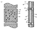
【図4】(a)は本発明による実施例1の壁面緑化ユニットを複数組み合わせた正面図であり、(b)は縦断面図である。
【図5】本発明による実施例2の壁面緑化ユニットの単体を示す斜視図である。
【図6】本発明による実施例2の壁面緑化ユニットの単体を示す分解斜視図である。
【図7】本発明による実施例2の壁面緑化ユニットの縦断面図である。
【図8】(a)は従来の植栽用壁体を示す正面図、(b)は従来の植栽壁体を示す斜視図、(c)は従来の植栽容器及び蓋を示す斜視図、(d)は従来の樋を示す斜視図である。
【図9】(a)は従来の緑化用コンテナを示す正面図、(b)は縦断面図、(c)は側面図である。
【図10】(a)は従来の壁面緑化ユニットを示す正面図、(b)は縦断面図である。
【符号の説明】
1…壁面緑化ユニット
2…受水蓋
2a…排水穴
2b…側板
2c…底板
3…前枠
3a…側板
4…トレー
4a…前面部
4b…底面部
4c…後面部
5…中板
5a…引込口
6…保水材
6a…保水マット
6c…保水ロープ
6d…保水ロープの上端
6e…保水ロープの下端
7…後枠
8…植栽土壌
9…植物
10…壁面
11…潅水パイプ
11a…穿孔部
12…前方係止片
13…後方折曲片
14…開口窓
15…開口部
16…側窓
17…排水穴
20…断熱材
21…植栽穴[0001]
TECHNICAL FIELD OF THE INVENTION
The present invention relates to a wall surface greening unit which is attached to a wall surface of a building or a side wall of a road to promote greening.
[0002]
[Prior art]
Conventionally, it was difficult to plant on the wall of a building or on the side wall of a road, but in recent years, technology development on wall greening that allows planting in such places has been performed. .
[0003]
By the way, technology of such wall greening can be roughly classified into a panel type, a net type, and a planter type.
[0004]
Among them, the panel type is one that allows plants to be rooted in thin layers made of various materials.Because there is little soil in the root pot, the plant that can be planted is not used because of its low water retention. It has the disadvantage of being limited to sedums and moss.
[0005]
In the case of the net type, a net-shaped member is attached to the side wall of the road, and the plants planted in the soil under the net are grown while tangling them with the net. There is a drawback that it is limited to vine climbing plants represented by.
[0006]
Therefore, focusing on the planter type as a greening method that allows planting of various types of plants in addition to the above-mentioned sedums, moss or vines, conventional planting methods are described with reference to Patent Documents 1 to 3 below. The technology will be described.
[0007]
First, the invention described in Patent Literature 1 includes, as shown in FIGS. 8A to 8D, a greening unit 50 that can be stacked in a plurality of stages, and each greening unit 50 includes a back plate 51a and a bottom plate. A main body 51 having an open front surface comprising a top plate 51b and a top plate 51c, and one or more planting containers 55 accommodated in the main body 51. The bottom plate 51b and the top plate 51c are provided with water supply holes at appropriate intervals. As shown in FIG. 8A, a plurality of the greening units 50 are arranged on a foundation 52, the side portions are supported by columns 53, and the upper portion is held by a cap 54 as shown in FIG. In such a state, it is attached to a side wall such as a road.
[0008]
In such a configuration, as shown in FIG. 8C, the planting container 55 has a rectangular parallelepiped container having an open front surface, is partitioned by a partition wall 58, and a plurality of planting rooms 59, 59. A communication hole 61 is provided in both side walls 60, 60, a water receiver 62 and a water supply hole 63 for storing water supply are provided in a ceiling portion, and a drain hole 64 is provided in a bottom portion. Alternatively, a drain hole 65 is provided, and a planting hole 66 corresponding to the planting room 59 and a splittable lid 68 having a plurality of ventilation holes 67 provided around the planting hole 66 are provided on the front surface. The planting room 59 is filled with artificial soil (not shown), and the artificial soil is preliminarily planted.
[0009]
Further, in the above configuration, a gutter 69 running in parallel above the top plate 51c is provided, and the gutter 69 is partitioned by the partition plate 70 at substantially the same pitch as the width of the planting room 59, and at the bottom of each partition. Is provided with a water supply hole 71, and further provided with a water supply tube 72 across the partition plate 70, so that water dropped from the water supply tube 72 is received by the partition unit.
[0010]
The invention described in Patent Literature 2 is a flat vertical container with a front open as shown in FIGS. 9A to 9C, and is installed at an angle in a container 75 at an interval. A greening container for walls or the like, characterized in that cells 77, 77 ... are formed in multiple layers at 76, 76 ..., and each cell 77 is filled with artificial soil 78 including artificial lightweight soil to form a vegetation substrate. is there.
[0011]
In such a configuration, a back plate 80 fixed to a wall surface of a building by bolts 79 or the like and the plurality of partition plates 76, 76... Are formed on the back plate 80, and both sides of each partition plate 76 are placed side by side. Are held by face plates 82, 82. Further, spaces 83 having a triangular cross section are formed at the uppermost portions of the partition plates 76, 76, and these triangular spaces 83 and the cells 77, 77 are filled. Plants are vegetated on artificial soils 78, 78.... Also, drain holes 84, 84,... Are formed in each of the partition plates 76, 76, so that the supply water or rainwater received in the uppermost triangular space 83 permeates downward through the drain holes 84, 84, and is discharged. I am trying to do it.
[0012]
The invention described in Patent Document 3 is classified as a panel type, and as shown in FIGS. 10 (a) and 10 (b), it can be attached to a wall surface of a building and has an opening at an upper surface. A case 88 having a water port 86 and a drainage hole 87 opening on the lower surface, a planting material 89 containing culture soil accommodated in the case 88, and a greenery planted in the planting material 89 and exposed on the outer surface of the case 88 It is a wall greening unit comprising a plant 90.
[0013]
In such a configuration, the planting material 89 is formed by laminating a water-permeable layer 91, a cultivation layer 92, and a planting layer 93 in a case 88, and a mesh 94 is formed on an outer surface of the planting layer 93. The mesh 94 prevents the plant material 89 from bending.
[0014]
[Patent Document 1]
Japanese Patent Application Laid-Open No. 9-9787 [Patent Document 2]
JP 2000-201536 A [Patent Document 3]
JP 2002-335765 A
[Problems to be solved by the invention]
By the way, the irrigation system according to the invention of Patent Document 1 shown in FIGS. 8A to 8D is configured such that the dripping from the water supply tube 72 provided above the top plate 51c is applied to each section of the gutter 69 by each partition plate 70. Through the water supply holes 71 provided at each bottom of each section of the gutter 69, and is dropped into the water receiver 62 of the lower planting container 55, and each of the lower plants is supplied from the water supply hole 63 of the water receiver 62. It is dropped into the planting room 59, further passes through the ventilation or drainage holes 65 provided at the bottom of each planting room 59, reaches further below each planting room 59, and is discharged through the bottom drainage hole 64. .
[0016]
However, according to the invention of Patent Literature 1, since the planting chambers 59, 59 ... of the planting container 55 are filled with artificial soil, the water supplied from above is not supplied to the planting chambers 59, 59 ... The artificial soil is sequentially infiltrated and reaches the lower planting room 59 through the ventilation or drainage hole 65, and the water supplied to the planting room 59 becomes insufficient as it goes down.
[0017]
Further, in the irrigation system according to the invention of Patent Document 2 shown in FIGS. 9A to 9C, water supply or rainwater received in the uppermost triangular space 83 passes through the drain holes 84 of the partition plates 76. Since the artificial soil 78, 78,... Of each cell 77, 77,...
[0018]
Further, in the invention of Patent Document 3 shown in FIGS. 10A and 10B, plants that can be planted are planted on the mat or sheet-like planting layer 93 and the plate-like cultivation layer 92 in order to root the greening plant 90. Is limited. In addition, this irrigation system is configured such that it penetrates downward from the water inlet 87 on the upper surface of the case 88 and penetrates the planting layer 93 and the cultivation layer 92 while passing through the water-permeable layer 91. Since water is supplied to each layer by the permeability of moisture generated by merely contacting, it becomes more difficult to supply moisture as it goes downward.
[0019]
The present invention has been made in order to solve the above-described problems, and is a planter type that can be planted with various kinds of plants so as to be attached to a wall surface of a building or a side wall of a road to promote greening. An object of the present invention is to provide a wall surface greening unit that ensures the supply of water not only upward but also downward by making the irrigation system retractable into each stage.
[0020]
[Means for Solving the Problems]
In order to solve the above problems, the wall greening unit according to claim 1 of the present invention is a single unit or a vertically stacked wall greening unit that is attached to a wall surface of a building or a road for planting. A water receiving lid for receiving moisture is provided at the top of the multiple units, and each unit holds a front frame that holds multiple trays in a state where the front is open at predetermined intervals in the vertical direction and the rear of each tray An intermediate plate, a water retaining material having moisture permeability provided on the rear surface of the intermediate plate, and a rear frame attached to the wall surface while holding the rear surface of the water retaining material, and from above through the water retaining material. The structure is such that the supplied water is drawn into each tray, so that the water supplied to the water retention material from the drain hole provided in the water receiving lid is distributed to the planting soil filled in each tray. It is characterized by.
[0021]
According to a second aspect of the present invention, in the wall surface greening unit according to the first aspect, the tray is formed such that a front portion and a rear portion are bent upward and backward of a bottom portion, and the front portion is formed higher than the rear portion. The front locking piece formed by bending the upper front part of each tray forward at the lower end of each opening window formed at a predetermined interval in the vertical direction of the front frame, and At the lower end of each opening formed at a predetermined interval in the vertical direction, a rear bent piece formed by bending the upper part of the rear surface of each tray backward is locked, and the rear bent piece has moisture permeability. By having a structure inserted into the inside of the water retention mat, the water supplied from above the water retention mat is pulled into each tray through the rear bent piece of each tray, and drainage holes provided in the bottom plate of the tray are provided. So that excess water is drained to the lower tray Characterized in that was.
[0022]
According to a third aspect of the present invention, in the wall surface greening unit according to the first aspect, the tray is formed by bending a front portion of a bottom portion upward and a rear portion of the bottom portion downward. And the supporting pieces of each tray are fixed at predetermined intervals in the vertical direction of the middle plate, and the front part and the upper part of the tray are covered with a heat insulating material and at the top of the heat insulating material. A plant planted in the tray is grown from the formed planting hole, and the lower end of a water-permeable rope provided between the middle plate and the rear frame and having moisture permeability is formed in the middle plate. With the structure inserted into each tray by inserting it through the inlet, the water supplied from above each water retention rope is drawn into each tray, and drainage holes provided in the middle plate at the rear lower part of the tray are provided. Excess water is discharged to the water retention rope side And it features.
[0023]
Furthermore, in the wall surface greening unit of claim 4 according to the present invention, in claim 1, 2 or 3, an irrigation pipe is provided above the water receiving lid, and water is supplied to the water receiving lid via the watering pipe. It is characterized by being supplied.
[0024]
BEST MODE FOR CARRYING OUT THE INVENTION
Hereinafter, embodiments of the present invention will be described with reference to the drawings.
[0025]
(Example 1)
The present invention provides, as shown in FIGS. 1 to 4, a wall greening unit 1 attached to a wall 10 such as a building or a road for planting, a single unit or a plurality of units 1 stacked vertically. A water receiving cover 2 for receiving moisture is provided at the uppermost part of each unit 1. Each unit 1 has a front frame 3 holding a plurality of trays 1, 1. A middle plate 5 for holding the rear portion of each of the trays 4, 4,..., A water retaining material 6 provided on the rear surface of the middle plate 5 and having water permeability, and a rear surface of the water retaining material 6 are held and attached to the wall surface 10. With a structure having a rear frame 7 and drawing water supplied from above through the water retaining material 6 into each tray 4, water is supplied to the water retaining material 6 from a drain hole 2 a provided in the water receiving cover 2. The distributed moisture is distributed to the planting soil 8 filled in each tray 4. One in which the.
[0026]
The first embodiment according to the present invention will be described in detail. As shown in FIGS. 1 to 4, the water receiving cover 2 is provided on the top of a single unit 1 or a plurality of units 1, 1. It is fixed and has a side plate 2b on the front, rear, left and right, and a long drainage hole 2a formed on the rear side of the bottom plate 2c. The water receiving lid 2 receives rainwater or is supplied from an irrigation pipe 11 described later. Upon receiving the water, the water is supplied from the drain hole 2a to the water retaining material 6 (the water retaining mat 6a in this embodiment) below.
[0027]
The wall greening units 1, 1... Shown in FIG. 4 are shown as a configuration in which two units 1, 1 are arranged in the horizontal direction and two units 1, 1 are stacked in the vertical direction. However, it is possible to arrange more units in the horizontal and vertical directions so as to cover a desired wall surface.
[0028]
In FIG. 4, a water receiving cover 2 is provided at the top, and irrigation pipes 11 are continuously provided above each water receiving cover 2. 2 may be provided, and an irrigation pipe 11 may be attached to each of the water receiving lids 2. In any case, the irrigation pipe 11 is supplied with water from a water storage tank provided on the rooftop of a building or a pump from the ground, and is sprinkled from the perforated portion 11a (see FIG. 3) of the irrigation pipe 11 as described above. At the receiving lid 2.
[0029]
As shown in FIG. 2 or FIG. 3, each tray 4 in each unit 1 has a front part 4a and a rear part 4c bent upward and backward before and after a horizontally long bottom part 4b, and the front part 4a has a rear part. 4c. In such a configuration, when the planting soil 8 is filled up to near the upper end of the rear surface 4c of each tray 4, the height of the front surface 4a of the tray 4 is higher than the upper surface of the planting soil 8, The plant soil 8 in the tray 4 and the supplied water are scattered and are hard to fall down, so that it is possible to prevent safety or inconvenience to passers below.
[0030]
Each tray 4 has the same shape, and has a front locking piece 12 formed by bending the upper end of the front part 4a forward and a rear bent piece formed by bending the upper end of the rear part 4c backward. 13. The front locking piece 12 and the rear bent piece 13 have a width that can be locked to the lower end of the opening 14 of the front frame 3 and the lower end of the opening 15 of the rear frame 7 as described later. Is formed.
[0031]
In FIG. 2, the front frame 3 has side plates 3a, 3a bent rearward on both left and right sides. A plurality of open windows 14, 14,... Are formed on the front surface of the front frame 3 at intervals in the vertical direction. Further, as shown in FIG. 3, the vertical interval between the opening windows 14 is formed so as to correspond to the vertical width of the front surface 4 a of each tray 4. When the front locking pieces 12 formed on the front 4a are locked, the trays 4 are hidden by the front frame 3 and cannot be seen from the outside. The plant 9 planted in the planting soil 8 grows outward and has a greened appearance as a whole.
[0032]
The left and right side frames 3a, 3a of the front frame 3 are formed with side windows 16 having opening windows 14 having the same height and vertical width, and the plants 9 planted in the planting soil 8 of the respective trays 4. Are also visible from the side window 16.
[0033]
On the other hand, at the lower end of each opening 15 formed at a predetermined interval in the vertical direction of the middle plate 5, a rear bent piece 13 formed by bending the upper part of the rear surface of each tray backward is locked. As shown in FIG. 3, the middle plate 5 is open from the lower tray 4 to the upper tray 4 by the opening 15 of the middle plate 5. The water retention mat 6a provided on the rear surface of the middle plate 5 is exposed to the tray 4 side.
[0034]
The water retention material 6 in the present embodiment is made of a water retention mat 6a having water permeability, and is formed in a rectangular plane using a polyester solid cotton sheet or a 3D nonwoven fabric. As shown in FIG. 3, the upper end of the water retaining mat 6a is brought into contact with the water receiving cover 2 directly below the drain hole 2a to drain rainwater received by the water receiving cover 2 and water supplied from an irrigation pipe 11 described later. The water retention mat 6a is immediately penetrated through the hole 2a.
[0035]
As shown in FIG. 2, insertion grooves are formed in the water retention mat 6a at the positions of the rear bent pieces 13 formed at the upper end of the rear surface of each tray 4, and as shown in FIG. By inserting the rear bent pieces 13 of the respective trays 4 into the insertion grooves 6b, the water supplied from above the water retention mat 6a can be received by the rear bent pieces 13 and drawn into the tray 3 as described above. it can.
[0036]
As shown in FIG. 3, a drain hole 17 is provided in the bottom plate 4 b of each tray 4, and the excess water supplied into the planting soil 8 is discharged to the lower tray 4 by the drain hole 17. , So that water can be supplied without waste.
[0037]
Further, in this embodiment, the rear frame 7 is fixed to the wall surface 10 of a building or the like by bolts or the like while holding the rear surface of the water retention material 6 (water retention mat 6a). Holding pieces 7a, 7a bent forward on both sides of the rear frame 7 are formed. After fixing the rear frame 7 to the wall surface 10, the holding pieces 7a, 7a on both sides of the rear frame 7 are attached to the front frame 3 Are fixed on the left and right side frames 3a, 3a by inserting bolts 7c (see FIG. 1) into the screw holes 3b of the side frames 3a and the screw holes 7b of the holding pieces 7a. 5, the trays 4, 4,... Can be attached between the middle plate 5 and the front plate 3 at predetermined intervals in the vertical direction. The left and right sides of the tray 4 are closed by left and right side plates 3a and 3a of the front frame 3.
[0038]
In such a configuration, each tray 4 locks the front locking piece 12 of the front face 4 a with the opening window 14 of the front frame 3, and the rear bent piece 13 of the rear face 4 c with the opening 15 of the middle plate 5. Due to the locked configuration, each tray 4 can be detached, and the plant 9 can be replaced for each tray 4.
[0039]
Further, in the above configuration, the front frame 3 uses an ABS resin to coat the surface thereof with a heat-reflective paint such as an acrylic resin to block the transmission of solar heat into the trays. It can protect the healthy growth of plants by preventing the temperature of roots from rising.
[0040]
Further, as another heat prevention structure, a space between the front frame 3 and the tray 4 is filled with foamed ABS resin or rock wool, a heat insulating material is attached to the front surface of the front frame 3 or applied, or further heat insulating. It is also effective to apply an infrared reflective sheet instead of a material, or to spray a heat reflecting or heat insulating paint.
[0041]
Further, as a material used for the tray 4, a lightweight metal such as aluminum or stainless steel may be used in addition to a high-strength resin material such as engineering plastic, a plastic material such as ABS resin or FRP. The middle plate 5 and the rear frame 7 can be made of a lightweight metal such as an aluminum plate.
[0042]
Further, artificial light soil such as natural pumice, coconut dust, coconut fiber, and peat moss can be used as the planting soil 8 to be filled in the tray 4. In this embodiment, the upper part of each tray 4 is opened. Therefore, the seedling to be planted in the tray is preferably a potted seedling. Suitable plants include perennials such as geraniums, roses, and pine trees, as well as pitting plants such as tsurusakisaki and hedera, and the like.
[0043]
(Example 2)
In this embodiment, as shown in FIGS. 5 to 7, a water receiving lid 2 similar to the above embodiment is provided for each single unit 1 or for a plurality of units 1, 1,. An irrigation pipe 11 similar to the above is provided at the top.
[0044]
In this embodiment, as shown in FIGS. 5 to 7, each tray 4 has a front part 4a formed by bending a front part of a bottom part 4b upward and a rear part of the bottom part 4b bent downward. And supporting pieces 4d of the respective trays 4 are fixed at predetermined intervals in the vertical direction of the intermediate plate 5.
[0045]
The material used for each tray 4 may be a high-strength resin material such as engineering plastic, a plastic material such as ABS resin or FRP, or a light metal plate such as aluminum or stainless steel, as in the above embodiment. Good.
[0046]
Further, as shown in FIG. 5 or FIG. 7, the front part and the upper part of each tray 4, 4,... Are covered with a heat insulating material 20, and the trays are formed through planting holes 21, 21,. The plant 9 planted in 4 is inserted and grown. As shown in FIG. 5, a plurality of such planting holes 21 may be formed at predetermined intervals according to the width of each tray 4, but are planted in the planting soil 8 in the tray 4. It is not necessary to pass the plant 9 through all the planting holes 21, and the plant 9 can be selectively inserted depending on the type of the plant, and even if there is an unused planting hole 21, the plant 9 can function as a ventilation hole.
[0047]
Further, the middle plate 5 and the rear frame 7 are both formed of aluminum or the like, and in this embodiment, the water retaining material 6 provided between the middle plate 5 and the rear frame 7 is made of cotton having moisture permeability. A water retention rope 6c such as a rope is provided. As shown in FIG. 7, each of the water retention ropes 6 c contacts or exposes the upper end 6 d to the drainage hole 2 a of the water receiving lid 2, so that rainwater received at the water receiving lid 2 or water supply from the irrigation pipe 11 is drained. Immediately penetrate the lower water retention rope 6c from 2a to supply water downward, and at the same time, insert the lower end 6e of each water retention rope 6c from a drop-in port 5a formed at a predetermined position of the middle plate 5 in each tray 4. With the structure inserted into the tray 4, the lower end 6 e of each water retention rope 6 c comes into contact with the planting soil 8 in each tray 4 and draws in moisture supplied from above into the planting soil 8 of each tray 4. It becomes possible.
[0048]
A drain hole 23 is formed in the middle plate 5 at the rear lower part of each tray 4, and the excess water in the planting soil 8 is discharged to the water retaining rope 6 c side by the drain hole 23 so that the water is drained to another tray. 4 can be supplied without waste.
[0049]
Further, also in this embodiment, the rear frame 7 holds the rear surface of the water retaining material 6 (water retaining rope 6c) and is fixed to the wall surface of the building by bolting or the like. As shown in FIG. The middle plate 5 is fixed to the both sides of the frame 7 with the holding pieces 7a, 7a bent forward via the water retention rope 6c, and the trays are bolted at predetermined intervals in the vertical direction of the middle plate 5, The tray 4 can be fixed by welding or bonding or the like. As shown in FIG. 5, the left and right sides of the tray 4 are closed by side plates 22 having heat insulating properties.
[0050]
Further, in the present embodiment having the above-described configuration, the heat insulating material 20 of each tray 4 is made of an ABS resin, and the surface thereof is coated with a heat reflective paint such as an acrylic resin, so that the solar heat is transmitted into the tray. To prevent the temperature of the root from rising, thereby protecting the healthy growth of the plant.
[0051]
Further, also in the present embodiment, artificial light soil such as natural pumice, coconut dust, coconut fiber, peat moss, etc. is used as the planting soil to be filled in the tray 4. In this embodiment, a heat insulating material 20 is provided on the upper part of each tray 4, and the plant 9 planted in the tray 4 is inserted and grown through the planting hole 21 formed in the heat insulating material 20. This makes it possible to prevent the scattering of plants that have weak roots in the early stage of planting, and is suitable for plug seedlings such as barbera and tehera.
[0052]
In the first or second embodiment, a scattering prevention net (not shown) is provided to cover the front surface of the wall greening unit 1 in order to more reliably prevent the planting soil 8 and the plants from scattering in the tray 4. You may.
[0053]
【The invention's effect】
As described above, according to the wall greening unit of the present invention, planter-type trays can be arranged at predetermined intervals in the vertical direction along the wall surface of a building, a road, or the like. By stacking in the horizontal or vertical direction, the wall surface is covered with a desired area, and it is not limited to plants that were possible in conventional wall greening, but it is possible to green the entire wall surface with excellent design by various plants. It becomes possible.
[0054]
Further, in the present invention, the irrigation system receives rainwater with a water receiving lid provided at the top of each single unit or a plurality of units stacked in the vertical direction, or supplies water supplied by an irrigation pipe with each water. By having a structure that draws water into each tray via a water retention mat or water retention rope attached to the entire surface of the unit, it is possible to ensure not only upward but also downward water supply, and it is provided on the bottom plate of each tray. The excess water in each tray can be drained and reused by the drain holes provided in the tray, or the drain holes provided in the middle plate at the rear lower part of each tray, which simplifies the irrigation system and reduces the labor for water management. It is possible to use water resources.
[0055]
Further, in the structure constituting each unit, the front part is formed higher than the rear part, or the front part and the upper part of each tray are covered with a heat insulating material, and the tray is formed through the planting holes formed at the upper part of the heat insulating material. The structure that grows the plants planted inside the tray makes it difficult for the planting soil in the tray and the supplied water to scatter and fall down, preventing safety or inconvenience to pedestrians below. It becomes possible.
[Brief description of the drawings]
FIG. 1 is a perspective view showing a single unit of a wall greening unit according to a first embodiment of the present invention.
FIG. 2 is an exploded perspective view showing a single unit of the wall greening unit according to the first embodiment of the present invention.
FIG. 3 is a longitudinal sectional view of the wall greening unit of the first embodiment according to the present invention.
FIG. 4A is a front view in which a plurality of wall greening units according to the first embodiment of the present invention are combined, and FIG. 4B is a longitudinal sectional view.
FIG. 5 is a perspective view showing a single unit of a wall greening unit according to a second embodiment of the present invention.
FIG. 6 is an exploded perspective view illustrating a single unit of a wall surface greening unit according to a second embodiment of the present invention.
FIG. 7 is a longitudinal sectional view of a wall greening unit according to a second embodiment of the present invention.
8A is a front view showing a conventional planting wall, FIG. 8B is a perspective view showing a conventional planting wall, and FIG. 8C is a perspective view showing a conventional planting container and a lid. And (d) is a perspective view showing a conventional gutter.
9A is a front view showing a conventional greening container, FIG. 9B is a longitudinal sectional view, and FIG. 9C is a side view.
10A is a front view showing a conventional wall greening unit, and FIG. 10B is a longitudinal sectional view.
[Explanation of symbols]
DESCRIPTION OF SYMBOLS 1 ... Wall surface greening unit 2 ... Water receiving lid 2a ... Drain hole 2b ... Side plate 2c ... Bottom plate 3 ... Front frame 3a ... Side plate 4 ... Tray 4a ... Front part 4b ... Bottom part 4c ... Rear part 5 ... Middle plate 5a ... Inlet Reference Signs List 6 water retention material 6a water retention mat 6c water retention rope 6d upper end of water retention rope 6e lower end of water retention rope 7 rear frame 8 planting soil 9 plant 10 wall surface 11 irrigation pipe 11a perforated part 12 front Locking piece 13 Backward bent piece 14 Opening window 15 Opening 16 Side window 17 Drainage hole 20 Insulation material 21 Planting hole