JP2004305433A - Slot machine - Google Patents
Slot machine Download PDFInfo
- Publication number
- JP2004305433A JP2004305433A JP2003103208A JP2003103208A JP2004305433A JP 2004305433 A JP2004305433 A JP 2004305433A JP 2003103208 A JP2003103208 A JP 2003103208A JP 2003103208 A JP2003103208 A JP 2003103208A JP 2004305433 A JP2004305433 A JP 2004305433A
- Authority
- JP
- Japan
- Prior art keywords
- front door
- housing
- reel
- slot machine
- reel device
- Prior art date
- Legal status (The legal status is an assumption and is not a legal conclusion. Google has not performed a legal analysis and makes no representation as to the accuracy of the status listed.)
- Pending
Links
Images


Landscapes
- Slot Machines And Peripheral Devices (AREA)
Abstract
Description
【0001】
【発明の属する技術分野】
この発明は、筐体及びその前面開口を開閉自在に閉塞する前扉とを備えたスロットマシンに関し、特に新旧の機種交換の容易化を図る技術に関する。
【0002】
【従来の技術】
従来、新旧の機種交換の容易化を図ったスロットマシンとしては、前扉にリール装置を着脱自在に取り付けたものや、筐体と前扉との間に、中枠を開閉自在に取り付け、この中枠にリール装置を取り付けたものがある。更に、前扉の下側に、受皿を着脱自在に取り付けたものも提案されている。
【0003】
ところが、このような従来のスロットマシンでは、新旧の機種交換が面倒であるという共通の問題点があった。即ち、スロットマシンは、一定期間経過すると、新機種に入れ替えられるが、このとき旧機種を取り外し、取り外したスペースに新機種を取り付けるという手法が一般的であった。
【0004】
そのため、新旧の機種の交換に時間が掛かり、機種交換のために、パチンコホールの営業時間を短縮したり、夜間の作業を強いることも多く、多大な労力と費用を要するという問題点があった。また、新機種、旧機種を丸ごと交換することから、それらの搬送や保管のための費用も多く掛かり、しかも旧機種を廃棄し、新機種を新たに製造するので、資源の無駄も多いという問題点もあった。
【0005】
そこで、このように新機種、旧機種を丸ごと交換するのではなく、スロットマシンの本体箱の前面開口を開閉自在に閉塞する前扉の上半部に、リール装置及び主基板を取り付け、ヒンジ装置によりこの前扉の上半部のみを筐体から分離可能に取り付けて前扉だけを交換できるようにすることが考えられている(例えば、特許文献1参照)。
【0006】
【特許文献1】
特開平13−95973号公報(段落[0049]及び図1)
【0007】
【発明が解決しようとする課題】
しかしながら、上記の手法では、例えば前扉の下半部側に各種のスイッチ類が残る構成の場合、これらスイッチ類は頻繁に操作されるものであり、耐久性の点から古いものを使い続けると性能が劣化するため、操作における信頼性や品質の低下を招くおそれがある。
【0008】
また、前扉のフレーム部分は、見た目にも傷がつきやすく、新機種のわりに前扉のフレームだけが傷を有することになり、見栄えという面で遊技者に対してあまり良くない印象を与える結果となる。
【0009】
そこで、本発明は、簡単な構成により、質や見栄え良く機種交換できるようにすることを目的とする。
【0010】
【課題を解決するための手段】
上記した目的を達成するために、本発明は、前面が開口した筐体と、表示窓が形成されると共にゲーム進行状況に応じた演出を行う演出手段及び各種操作スイッチ類が装備され前記筐体の一側に開閉自在に取り付けられた前扉とを備え、前記筐体と前記前扉との間に、複数個のリール及びこれらのリールの駆動用モータを有し前記表示窓に臨むリール装置と、前記リール装置のゲーム結果に基づいて遊技者にメダルを排出するメダル排出装置と、前記リール装置及び前記メダル排出装置を制御する主制御装置と、前記主制御装置からの信号を受けて前記演出手段を制御する補助制御装置と、前記リール装置、前記メダル排出装置、前記主制御装置及び前記補助制御装置に電源供給する電源装置と、外部出力端子を有する集中端子板とが配設されて成るスロットマシンにおいて、前記前扉が前記筐体に対して分離可能に取り付けられ、前記前扉に、前記リール装置、前記主制御装置及び前記補助制御装置が取り付けられ、前記筐体内に、前記メダル排出装置、前記電源装置及び前記集中端子板が配設されていることを特徴としている(請求項1)。
【0011】
このような構成によれば、前扉を筐体から分離することで、前扉及びこれに取り付けられているリール装置、主制御装置、補助制御装置を新しい機種用に簡単に交換することができる。このとき、通常前扉に装備されている操作スイッチ類も一緒に交換されるため、質や見栄え良く機種交換することができる。
【0012】
また、本発明は、前記リール装置が、前記前扉に対して着脱自在に取り付けられ、前記主制御装置が、前記リール装置に取り付けられていることを特徴としている(請求項2)。このような構成によれば、リール装置及び主制御装置を前扉から分離できるため、リール装置及び主制御装置を前扉から分離しない場合に比べて、交換時における梱包用箱の容積を小さくすることができて有利である。
【0013】
また、本発明は、前記前扉が、ほぼ中央部で折曲可能に形成されていることを特徴としている(請求項3)。このとき、請求項4に記載のように、前記前扉が、複数箇所で折曲可能に形成されていてもよい。
【0014】
このような構成によれば、前扉を折曲することで、梱包用箱を小さくすることができて梱包効率を改善することができる。
【0015】
また、本発明は、前面が開口した筐体と、表示窓が形成されると共にゲーム進行状況に応じた演出を行う演出手段及び各種操作スイッチ類が装備され前記筐体の一側に開閉自在に取り付けられた前扉とを備え、前記筐体と前記前扉との間に、複数個のリール及びこれらのリールの駆動用モータを有し前記表示窓に臨むリール装置と、前記リール装置のゲーム結果に基づいて遊技者にメダルを排出するメダル排出装置と、前記リール装置及び前記メダル排出装置を制御する主制御装置と、前記主制御装置からの信号を受けて前記演出手段を制御する補助制御装置と、前記リール装置、前記メダル排出装置、前記主制御装置及び前記補助制御装置に電源供給する電源装置と、外部出力端子を有する集中端子板とが配設されて成るスロットマシンにおいて、前記前扉が、扉枠体と、この扉枠体に着脱自在に装着された複数のパネル枠体と、前記各パネル枠体それぞれに着脱自在に取り付けられた複数のパネルとを備えていることを特徴としている(請求項5)。
【0016】
このような構成によれば、機種交換を行う際、複数のパネルを各パネル枠体それぞれから取り外すことで、各パネルのみを交換すればよく、新機種に要する部品コストを大幅に低減することができ、新機種に要する部品重量も軽減できて運搬が非常に容易になる。そして、これらパネルはホールにおいても容易に交換できるため、交換作業を非常に手軽に行うことができる。
【0017】
このとき、請求項6に記載のように、前記パネル枠体が、上、中、下に分離可能であり、これら上、中、下の各パネル枠体それぞれに前記パネルが着脱自在に取り付けられているのが望ましい。こうすると、スロットマシンの場合、前面の装飾デザインの観点からいえば、ほぼ上、中、下に分けることができるため、上、中、下の3つのパネルを分離可能にしておけば、前扉を新しいデザイン交換する手間が非常に簡素化することができる。
【0018】
また、本発明は、前記主制御装置及び補助制御装置が、前記リール装置に取り付けられていることを特徴としている(請求項7)。このような構成によれば、リール装置と共に主制御装置及び補助制御装置を一緒に交換することができ、主制御装置及び補助制御装置付きのリール装置をホールにおいて交換できるため、交換効率を大幅に改善することができる。
【0019】
また、本発明は、前記リール装置の前記駆動用モータと前記電源装置とを電気的に接続するためのコネクタを備え、前記コネクタが、前記筐体に固定して設けられた筐体側コネクタ部と、前記リール装置に固定して設けられ前記筐体側コネクタ部に抜き差し自在に挿入されるリール側コネクタ部とから成ることを特徴としている(請求項8)。
【0020】
このような構成によれば、リール装置の交換の際に、筐体側コネクタ部とリール側コネクタ部とを抜き差しすればよいため、リール装置の電気的接続部分の切離を非常に容易に行うことができる。
【0021】
また、本発明は、前記筐体内に設けられ前記リール装置が載置される棚を備えていることを特徴としている(請求項9)。このような構成によれば、リール装置を筐体側の棚上に載置すればよいため、リール装置の交換が極めて容易になる。
【0022】
また、本発明は、前記棚の上面に形成され前記リール装置の着脱時のガイドとなるガイド手段を備えていることを特徴としている(請求項10)。このような構成によれば、ガイド手段を使ってリール装置を移動させればよいため、リール装置の交換がよりいっそう容易になる。
【0023】
このとき、請求項11に記載のように、前記筐体の内側に、前記リール装置の着脱時のガイドとなるガイド手段が形成されていてもよい。このようにすれば、筐体に棚を設けるスペースがない場合において有利であり、ガイド手段を使ってリール装置を移動させればよいため、リール装置の交換がよりいっそう容易になる。
【0024】
【発明の実施の形態】
(第1実施形態)
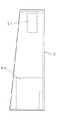
この発明の第1実施形態について図1ないし図7を参照して説明する。但し、図1はスロットマシンの正面図、図2は分離状態における前扉の平面図、図3及び図4は分離状態の前扉を折曲した状態における正面図及び右側面図、図5ないし図7はそれぞれ分離状態における筐体の正面図、右側面図及び平面図である。
【0025】
本実施形態におけるスロットマシンは、例えば図1に示すように構成されている。即ち、図1に示すように、スロットマシン1では、筐体3の前面開口が前扉5により開閉自在に閉塞され、この前扉5の左端部がヒンジ装置により筐体3に回転自在に支持され、筐体3の前面全体が前扉5により覆われて閉塞される。また、ヒンジ装置には、周知のワンタッチ式スライド蝶番や、抜き差し蝶番が使用され、前扉5が筐体3に対して分離可能に取り付けられている。
【0026】
ところで、前扉5の上部には所定の装飾が施された上パネル7が装着され、この上パネル7の内側には演出手段としてのランプが配設され、ゲームの状況に応じ、このランプが点滅されて所定の演出を行うようになっている。
【0027】
また、前扉5の中央部には中パネル9が装着され、この中パネル9には、装飾によって3個の矩形の透明なリール表示窓11が並設され、各リール表示窓11の内側には後で詳述するリール装置の左、中、右の各リール13L,13M,13Rが各リール表示窓11に臨むように配設されている。更に、前扉5の下部にはマシン名などの装飾が施された下パネル15が装着されている。
【0028】
尚、中パネル9には上下に平行な3本及び斜めに2本の入賞ラインが描かれると共に、入賞ライン中の有効ラインを表示する有効表示ランプや、ボーナスゲームの状態などを表示する演出手段としての種々の演出表示ランプ、クレジットメダルの枚数を表示するメダル枚数表示器が中パネル9に配設されている。
【0029】
そして、前扉5の中パネル9と下パネル15との間には操作板17が配設され、この操作板17には、クレジットされているメダル枚数から1回押す毎に1枚、2枚、3枚を順次減じてメダル投入に代えるためのベットスイッチ21のほか、1回押すだけでクレジットされているメダル枚数から最大掛け枚数である3枚を減じてメダル投入に代えるためのマックスベットスイッチ23、各リールの回転を開始させるためのスタートレバー25、左、中、右の各リール13L,13M,13Rの回転を停止操作するための第1ないし第3ストップスイッチ27,29,31、及び、メダル投入口33や貯留メダルを払い出すための精算スイッチ35が設けられている。更に、下パネル15の下方にはメダル払出口やメダル受け37が設けられている。
【0030】
ところで、前扉5は、上記したように筐体3に対して分離可能に取り付けられ、しかも図2〜4に示すように、この前扉5は、操作板17と下パネル15との間で蝶番により上半部と下半部が連結されてほぼ中央部で折曲可能に形成されている。
【0031】
更に、図2〜7に示すように、筐体3と前扉5との間には、各リール13L,13M,13R及びこれらの駆動用モータ(図示せず)を有しリール表示窓11に臨むリール装置41と、このリール装置41のゲーム結果に基づいて遊技者にメダルを排出するメダル排出装置43と、リール装置41及びメダル排出装置43を制御する主制御装置を備えた主基板45と、主基板45の主制御装置からの信号を受けて演出手段であるランプ等を制御する補助制御装置を備えた補助基板47と、リール装置41、メダル排出装置43、主基板45及び補助基板47に電源供給する電源装置49と、外部出力端子を有する集中端子板51とが配設されている。
【0032】
ここで、リール装置41は、複数の保持部材を枠体状に組み合わせてなるリールスタンド53に、各リール13L,13M,13Rの駆動用モータを取り付け、これらモータの回転軸それぞれに各リール13L,13M,13Rの中心を軸着して形成されている。
【0033】
そして、図4に示すように、このようなリール装置41のリールスタンド53の上面に主基板45が取り付けられると共に、前扉5の上パネル7の背面に補助基板47が取り付けられ、前扉5にリール装置41、主基板45及び補助基板47が配設されている。
【0034】
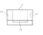
また、図5〜7に示すように、筐体3内の底部ほぼ中央にメダル排出装置43が配設されると共に、筐体3内の底部左側に電源装置49が配設され、筐体3内右側上部に集中端子板51が配設されている。
【0035】
従って、第1実施形態によれば、前扉5を筐体3から分離することで、前扉5及びこれに取り付けられているリール装置41、主基板45、補助基板47を新しい機種用に簡単に交換することができる。
【0036】
更に、前扉5に装備されている操作スイッチ類21,23,25,27,29,31,35も前扉5と一緒に新しいものに交換されるため、従来のように、操作スイッチ類に傷等がついたままになることもなく、質や見栄え良く機種交換することができる。
【0037】
また、前扉5が、ほぼ中央部で折曲可能に形成されているため、前扉5を折曲することで、梱包用箱を小さくすることができて梱包効率を改善することができる。尚、前扉5は、3箇所以上で折曲可能な構造であっても構わない。
【0038】
このとき、第1実施形態では、前扉5はその中央部で折曲可能に形成している例を示したが、変形例として、図8に示すように、前扉5は折曲できない構造であってもよい。
【0039】
(第2実施形態)
次に、この発明の第2実施形態について図9及び図10を参照して説明する。但し、スロットマシンの基本的な構成は上記した第1実施形態と同じであり、重複を避けるために、以下では第1実施形態と相違する点について説明する。そのとき、図1ないし図7と同一符号は同一もしくは相当するものを示すものとする。
【0040】
本実施形態では、前扉5に対してリール装置41を着脱自在に取り付けた点が、上記した第1実施形態と相違しており、リール装置41には主基板45が取り付けられているため、リール装置41及び主基板45が一体的に新機種のものに交換される。尚、リール装置41はリールスタンド53の前側に、例えばフック体を設け、このフック体を前扉5の背面側の係合部に係合することでリール装置41を前扉5に着脱自在に取り付けるようにすればよい。
【0041】
従って、第2実施形態によれば、上記した第1実施形態と同等の効果を得ることができるのは勿論のこと、リール装置41及び主基板45を前扉5から分離できるため、梱包用箱を小さくすることができて梱包効率をいっそう改善することができる。
【0042】
このとき、前扉5を少なくとも1箇所で折曲可能に構成すれば、更に梱包用箱を小さくすることができ、梱包効率を大幅に改善することができる。
【0043】
(第3実施形態)
続いて、この発明の第3実施形態について図11ないし図13を参照して説明する。但し、スロットマシンの基本的な構成は上記した第1実施形態と同じであり、重複を避けるために、以下では第1実施形態と相違する点について説明する。そのとき、図1ないし図7と同一符号は同一もしくは相当するものを示すものとする。
【0044】
本実施形態では、前扉5が、扉枠体55と、この扉枠体55に着脱自在に装着された上、中、下のパネル枠体57,59,61とを備え、これら各パネル枠体57,59,61に着脱自在に上、中、下パネル7,9,15がそれぞれ取り付けられるようになっている。ここで、各パネル枠体57,59,61は、フックにより扉枠体55の所定位置にそれぞれ着脱自在に取り付けられるようにするのが望ましい。
【0045】
ところで、図11に示すように、リール装置41が第2実施形態と同様、前扉5に対して着脱自在に取り付けられており、主基板45及び補助基板47はリール装置41のリールスタンド53に取り付けられ、リール装置41と共に前扉5に着脱自在に取り外し可能になっている。
【0046】
そして、リール装置41の各駆動用モータと電源装置49とを電気的に接続するためのコネクタ63が設けられ、このコネクタ63は、筐体3内側の中央やや下寄りの位置に設けられた棚65の中央奥部に固定して設けられた一対の筐体側コネクタ部63Kと、リール装置41のリールスタンド53の下奥部に固定して設けられ一対の筐体側コネクタ部63Kに抜き差し自在に挿入されるリール側コネクタ部63Rとにより構成されている。尚、棚65の両筐体側コネクタ部63Kの間には前方に突出した位置決めピン67が設けられており、この位置決めピン67がリール装置41側に設けられた位置決め孔に嵌挿して、特にコネクタ63の接続時の位置決めが行われる。
【0047】
また、筐体3内に設けられた棚65上にリール装置41が載置されるが、この棚65の上面左右端部にはガイド体69が形成されており、リール装置41のリールスタンド53の左、右下端部がリール装置41の着脱時に両ガイド体69それぞれによりガイドされるようになっている。ここで、このガイド体69は、例えば断面L字状のレール状部材でよく、これらガイド体69と位置決めピン67により本発明におけるガイド手段が構成されている。ここで、ガイド体69によりリール装置41の大まかな位置決めをおこなうことができ、ピン67によりコネクタ63の接続時の位置決めを確実に行うことができる。尚、位置決めピン67は必ずしも設ける必要はない。
【0048】
従って、第3実施形態によれば、上記した第1実施形態と同等の効果を得ることができるのは勿論のこと、機種交換を行う際、各パネル7,9,15を各パネル枠体57,59,61それぞれから取り外し、リール装置41を前扉5から取り外すことで、各パネル7,9,15、リール装置41及び主、補助基板45,47のみを交換すればよく、新機種に要する部品コストを大幅に低減することができ、しかも新機種に要する部品重量も軽減できて運搬が非常に容易になる。
【0049】
このとき、スロットマシン1の前面はデザイン的にほぼ上、中、下に分けることができるため、上、中、下の3つのパネル7,9,15を分離可能にしておけば、前扉5を新しいデザイン交換する手間が非常に簡素化することができる。そして、パネル7,9,15をホールで交換できるため、交換作業を非常に手軽に行うことができる。
【0050】
また、リール装置41と共に主基板45及び補助基板47を一緒に交換することができ、主基板45及び補助基板47付きのリール装置41をホールにおいて交換でき、上記したようなパネル7,9,15含めて、最小限の交換で機種交換をホールで行えることになり、交換効率を大幅に改善することができる。
【0051】
更に、リール装置41の交換の際に、コネクタ63を構成する筐体側コネクタ部63Kとリール側コネクタ部63Rとを抜き差しすればよいため、リール装置41の電気的接続部分の切離を非常に容易に行うことができる。
【0052】
また、ガイド体69を棚の上面に設けているため、ガイド体69に沿ってリール装置41を移動させればよいため、リール装置41の交換をよりいっそう容易に行うことができる。
【0053】
なお、本発明は上記した実施形態に限定されるものではなく、その趣旨を逸脱しない限りにおいて上述したもの以外に種々の変更を行うことが可能である。
【0054】
例えば、上記した第3実施形態における棚65をなくし、筐体3左右の両内側面にガイド体69と同様の機能を有するガイド手段を直接形成し、リール装置41の着脱時のガイドとしてもよい。
【0055】
また、ガイド手段は、上記した構成に限定されるものでないのは勿論である。
【0056】
【発明の効果】
以上のように、請求項1に記載の発明によれば、前扉を筐体から分離することで、前扉及びこれに取り付けられているリール装置、主制御装置、補助制御装置を新しい機種用に簡単に交換することが可能になる。そして、通常前扉に装備されている操作スイッチ類も一緒に交換されるため、質や見栄え良く機種交換することが可能になる。
【0057】
また、請求項2に記載の発明によれば、リール装置及び主制御装置を前扉から分離できるため、リール装置及び主制御装置を前扉から分離しない場合に比べて、交換時における梱包用箱の容積を小さくすることができて非常に有利である。
【0058】
また、請求項3,4に記載の発明によれば、前扉を折曲することで、梱包用箱を小さくすることができて梱包効率を大幅に改善することが可能になる。
【0059】
また、請求項5に記載の発明によれば、機種交換を行う際、複数のパネルを各パネル枠体それぞれから取り外すことで、各パネルのみを交換すればよく、新機種に要する部品コストを大幅に低減することが可能になり、新機種に要する部品重量も軽減できて運搬が非常に容易になる。
【0060】
また、請求項6に記載の発明によれば、スロットマシンの場合、装飾デザインの観点からいえば、ほぼ上、中、下に分けることができるため、上、中、下の3つのパネルを分離可能にしておけば、前扉を新しいデザイン交換する手間が非常に簡素化することが可能になる。
【0061】
また、請求項7に記載の発明によれば、リール装置と共に主制御装置及び補助制御装置を一緒に交換することができ、主制御装置及び補助制御装置付きのリール装置をホールにおいて交換できるため、交換効率を大幅に改善することが可能になる。
【0062】
また、請求項8に記載の発明によれば、リール装置の交換の際に、筐体側コネクタ部とリール側コネクタ部とを抜き差しすればよいため、リール装置の電気的接続部分の切離を非常に容易に行うことが可能になる。
【0063】
また、請求項9に記載の発明によれば、リール装置を筐体側の棚上に載置すればよいため、リール装置の交換が極めて容易になる。
【0064】
また、請求項10に記載の発明によれば、ガイド手段を使ってリール装置を移動させればよいため、リール装置の交換をよりいっそう容易に行うことが可能になる。
【0065】
また、請求項11に記載の発明によれば、筐体に棚を設けるスペースがない場合において有利であり、ガイド手段を使ってリール装置を移動させればよいため、リール装置の交換をよりいっそう容易に行うことが可能になる。
【図面の簡単な説明】
【図1】この発明の第1実施形態におけるスロットマシンの正面図である。
【図2】この発明の第1実施形態におけるスロットマシンの分離状態における前扉の平面図である。
【図3】この発明の第1実施形態におけるスロットマシンの分離状態の前扉を折曲した状態における正面図である。
【図4】この発明の第1実施形態におけるスロットマシンの分離状態の前扉を折曲した状態における右側面図である。
【図5】この発明の第1実施形態におけるスロットマシンの分離状態における筐体の正面図である。
【図6】この発明の第1実施形態におけるスロットマシンの分離状態における筐体の右側面図である。
【図7】この発明の第1実施形態におけるスロットマシンの分離状態における筐体の平面図である。
【図8】第1実施形態の変形例における分離状態の前扉の右側面図である。
【図9】この発明の第2実施形態におけるスロットマシンの分離状態の前扉の右側面図である。
【図10】この発明の第2実施形態におけるスロットマシンの分離状態の前扉の平面図である。
【図11】この発明の第3実施形態におけるスロットマシンの分離状態の右側面図である。
【図12】この発明の第3実施形態におけるスロットマシンの分離状態の平面図である。
【図13】(a)〜(c)は第3実施形態におけるスロットマシンの各パネルの正面図である。
【符号の説明】
1 スロットマシン
3 筐体
5 前扉
7 上パネル
9 中パネル
11 リール表示窓
13L,13M,13R 左、中、右リール
15 下パネル
41 リール装置
43 メダル排出装置
45 主基板
47 補助基板
49 電源装置
51 集中端子板
55 扉枠体
57,59,61 パネル枠体
63 コネクタ
63K 筐体側コネクタ部
63R リール側コネクタ部
65 棚
67 位置決めピン(ガイド手段)
69 ガイド体(ガイド手段)[0001]
TECHNICAL FIELD OF THE INVENTION
The present invention relates to a slot machine provided with a housing and a front door for opening and closing a front opening of the housing, and more particularly, to a technique for facilitating replacement of old and new models.
[0002]
[Prior art]
Conventionally, as a slot machine that has facilitated the exchange of old and new models, there is a slot machine with a reel device detachably attached to the front door, and a middle frame between the housing and the front door that can be freely opened and closed. Some have a reel device attached to a middle frame. Further, there has been proposed an apparatus in which a saucer is detachably attached to a lower side of a front door.
[0003]
However, such a conventional slot machine has a common problem that it is troublesome to exchange old and new models. That is, the slot machine is replaced with a new model after a certain period of time. At this time, a method of removing the old model and attaching the new model to the removed space has been generally used.
[0004]
For this reason, it takes time to replace the old and new models, and in order to replace the models, the pachinko hall business hours are often shortened and nighttime work is often required, resulting in a problem that a lot of labor and cost are required. . In addition, since the new model and the old model are completely replaced, the cost for transporting and storing them is also high, and the old model is discarded and a new model is newly manufactured, which wastes resources. There were also points.
[0005]
Therefore, instead of replacing the new model and the old model in their entirety, the reel device and the main board are attached to the upper half of the front door that opens and closes the front opening of the main body box of the slot machine. It is proposed that only the upper half of the front door is detachably attached to the housing so that only the front door can be replaced (for example, see Patent Document 1).
[0006]
[Patent Document 1]
JP-A-13-95973 (paragraph [0049] and FIG. 1)
[0007]
[Problems to be solved by the invention]
However, in the above-described method, for example, in the case of a configuration in which various switches are left on the lower half side of the front door, these switches are frequently operated. Since the performance is deteriorated, there is a possibility that the reliability and the quality of the operation are deteriorated.
[0008]
In addition, the front door frame part is easily damaged in appearance, and only the front door frame has scratches instead of the new model, resulting in a bad impression for the player in terms of appearance It becomes.
[0009]
Therefore, an object of the present invention is to make it possible to exchange models with a simple configuration with good quality and good appearance.
[0010]
[Means for Solving the Problems]
In order to achieve the above-mentioned object, the present invention provides a housing having a front opening, a display window, and an effect unit for performing an effect according to the progress of a game and various operation switches. A front door that is openably and closably attached to one side of the reel, and a reel device that has a plurality of reels and a drive motor for these reels between the housing and the front door and faces the display window. A medal ejection device that ejects medals to a player based on a game result of the reel device, a main control device that controls the reel device and the medal ejection device, and a signal that is received from the main control device. An auxiliary control device for controlling the production means, a power supply device for supplying power to the reel device, the medal ejection device, the main control device and the auxiliary control device, and a centralized terminal plate having an external output terminal are provided. In the slot machine, the front door is detachably attached to the housing, the reel device, the main control device and the auxiliary control device are attached to the front door, and the inside of the housing is A medal discharge device, the power supply device, and the centralized terminal board are provided (claim 1).
[0011]
According to such a configuration, by separating the front door from the housing, the front door and the reel device, the main control device, and the auxiliary control device attached to the front door can be easily replaced for a new model. . At this time, the operation switches normally mounted on the front door are also replaced together, so that the models can be replaced with good quality and appearance.
[0012]
Further, the present invention is characterized in that the reel device is detachably attached to the front door, and the main control device is attached to the reel device (claim 2). According to such a configuration, since the reel device and the main control device can be separated from the front door, the volume of the packing box at the time of replacement is reduced as compared with a case where the reel device and the main control device are not separated from the front door. Advantageously.
[0013]
Further, the present invention is characterized in that the front door is formed so as to be able to be bent at a substantially central portion (claim 3). At this time, as described in
[0014]
According to such a configuration, by folding the front door, the size of the packing box can be reduced, and the packing efficiency can be improved.
[0015]
In addition, the present invention is provided with a housing having an open front, a display window, and a rendering means for performing a rendering in accordance with the progress of the game, and various operation switches. A reel device having a front door attached thereto, a plurality of reels and a drive motor for driving these reels between the housing and the front door, the reel device facing the display window, and a game for the reel device. A medal ejection device for ejecting medals to a player based on the result, a main control device for controlling the reel device and the medal ejection device, and an auxiliary control for controlling the effect means in response to a signal from the main control device Device, a power supply device for supplying power to the reel device, the medal discharge device, the main control device and the auxiliary control device, and a centralized terminal plate having an external output terminal. Wherein the front door includes a door frame, a plurality of panel frames detachably attached to the door frame, and a plurality of panels detachably attached to each of the panel frames. (Claim 5).
[0016]
According to such a configuration, when exchanging the model, a plurality of panels are removed from each panel frame, so that only each panel needs to be exchanged, and the component cost required for the new model can be greatly reduced. Yes, the weight of parts required for the new model can be reduced and transportation becomes very easy. Since these panels can be easily replaced in the hall, the replacement operation can be performed very easily.
[0017]
At this time, as described in
[0018]
Further, the present invention is characterized in that the main control device and the auxiliary control device are mounted on the reel device (claim 7). According to such a configuration, the main control device and the auxiliary control device can be exchanged together with the reel device, and the reel device with the main control device and the auxiliary control device can be exchanged in the hall. Can be improved.
[0019]
Further, the present invention includes a connector for electrically connecting the drive motor of the reel device and the power supply device, wherein the connector is provided on a housing-side connector portion fixed to the housing. And a reel-side connector portion fixedly provided on the reel device and inserted into and removed from the housing-side connector portion in a detachable manner.
[0020]
According to such a configuration, when the reel device is replaced, it is only necessary to remove and insert the housing side connector portion and the reel side connector portion, so that the electrical connection portion of the reel device can be very easily separated. Can be.
[0021]
Further, the present invention is characterized in that a shelf provided in the housing and on which the reel device is placed is provided (claim 9). According to such a configuration, it is only necessary to place the reel device on the shelf on the housing side, so that the replacement of the reel device becomes extremely easy.
[0022]
Further, the present invention is characterized in that there is provided a guide means formed on the upper surface of the shelf and serving as a guide when attaching and detaching the reel device (claim 10). According to such a configuration, the reel device may be moved using the guide means, and thus the replacement of the reel device is further facilitated.
[0023]
At this time, a guide means serving as a guide for attaching and detaching the reel device may be formed inside the housing, as described in claim 11. This is advantageous in the case where there is no space for providing a shelf in the housing, and the reel device can be moved using the guide means, so that the replacement of the reel device is further facilitated.
[0024]
BEST MODE FOR CARRYING OUT THE INVENTION
(1st Embodiment)
A first embodiment of the present invention will be described with reference to FIGS. 1 is a front view of the slot machine, FIG. 2 is a plan view of the front door in a separated state, FIGS. 3 and 4 are a front view and a right side view in a state where the front door in a separated state is bent, and FIGS. FIG. 7 is a front view, a right side view, and a plan view of the housing in a separated state.
[0025]
The slot machine according to the present embodiment is configured as shown in FIG. 1, for example. That is, as shown in FIG. 1, in the
[0026]
By the way, an
[0027]
A
[0028]
On the
[0029]
An
[0030]
Meanwhile, the
[0031]
Further, as shown in FIGS. 2 to 7, between the
[0032]
Here, the
[0033]
Then, as shown in FIG. 4, a
[0034]
As shown in FIGS. 5 to 7, a
[0035]
Therefore, according to the first embodiment, by separating the
[0036]
Further, the operation switches 21, 23, 25, 27, 29, 31, and 35 provided on the
[0037]
Further, since the
[0038]
At this time, in the first embodiment, an example is shown in which the
[0039]
(2nd Embodiment)
Next, a second embodiment of the present invention will be described with reference to FIGS. However, the basic configuration of the slot machine is the same as that of the above-described first embodiment, and the points that are different from the first embodiment will be described below to avoid duplication. At this time, the same reference numerals as those in FIGS. 1 to 7 indicate the same or corresponding components.
[0040]
The present embodiment is different from the above-described first embodiment in that the
[0041]
Therefore, according to the second embodiment, the
[0042]
At this time, if the
[0043]
(Third embodiment)
Next, a third embodiment of the present invention will be described with reference to FIGS. However, the basic configuration of the slot machine is the same as that of the above-described first embodiment, and the points that are different from the first embodiment will be described below to avoid duplication. At this time, the same reference numerals as those in FIGS. 1 to 7 indicate the same or corresponding components.
[0044]
In the present embodiment, the
[0045]
By the way, as shown in FIG. 11, the
[0046]
A
[0047]
The
[0048]
Therefore, according to the third embodiment, not only can the same effects as in the first embodiment described above be obtained, but also when replacing the model, each
[0049]
At this time, the front surface of the
[0050]
In addition, the
[0051]
Further, when the
[0052]
Further, since the
[0053]
The present invention is not limited to the above-described embodiment, and various changes other than those described above can be made without departing from the gist of the present invention.
[0054]
For example, the shelf 65 in the third embodiment described above may be eliminated, and guide means having the same function as the
[0055]
Also, the guide means is not limited to the above-described configuration.
[0056]
【The invention's effect】
As described above, according to the first aspect of the invention, by separating the front door from the housing, the front door and the reel device, the main control device, and the auxiliary control device attached to the front door can be used for a new model. Can be easily replaced. Since the operation switches normally provided on the front door are also exchanged together, it is possible to exchange the models with good quality and appearance.
[0057]
According to the second aspect of the present invention, since the reel device and the main control device can be separated from the front door, the packing box at the time of replacement can be compared with a case where the reel device and the main control device are not separated from the front door. It is very advantageous to be able to reduce the volume.
[0058]
According to the third and fourth aspects of the present invention, by folding the front door, the size of the packing box can be reduced, and the packing efficiency can be greatly improved.
[0059]
According to the fifth aspect of the present invention, when replacing a model, a plurality of panels are removed from each of the panel frames, so that only each panel needs to be replaced, and the component cost required for a new model is greatly reduced. Can be reduced, the weight of parts required for the new model can be reduced, and transportation becomes very easy.
[0060]
According to the invention described in
[0061]
According to the invention of
[0062]
According to the eighth aspect of the present invention, when the reel device is replaced, the housing-side connector portion and the reel-side connector portion only have to be inserted and removed, so that the electrical connection portion of the reel device is extremely disconnected. Can be easily performed.
[0063]
According to the ninth aspect of the present invention, since the reel device only needs to be mounted on the shelf on the housing side, the replacement of the reel device becomes extremely easy.
[0064]
According to the tenth aspect of the present invention, since the reel device may be moved using the guide means, it is possible to more easily replace the reel device.
[0065]
According to the eleventh aspect of the present invention, it is advantageous in a case where there is no space for providing a shelf in the housing, and since the reel device may be moved using the guide means, the replacement of the reel device is further improved. It can be easily performed.
[Brief description of the drawings]
FIG. 1 is a front view of a slot machine according to a first embodiment of the present invention.
FIG. 2 is a plan view of the front door in a separated state of the slot machine according to the first embodiment of the present invention.
FIG. 3 is a front view of the slot machine according to the first embodiment of the present invention in a state where the front door is bent in a separated state.
FIG. 4 is a right side view of the slot machine according to the first embodiment of the present invention in a state where the front door is bent in a separated state.
FIG. 5 is a front view of the housing of the slot machine according to the first embodiment of the present invention in a separated state.
FIG. 6 is a right side view of the housing of the slot machine according to the first embodiment of the present invention in a separated state.
FIG. 7 is a plan view of the housing of the slot machine according to the first embodiment of the present invention in a separated state.
FIG. 8 is a right side view of a front door in a separated state according to a modified example of the first embodiment.
FIG. 9 is a right side view of the front door of the slot machine according to the second embodiment of the present invention in a separated state.
FIG. 10 is a plan view of the front door of the slot machine in a separated state according to the second embodiment of the present invention.
FIG. 11 is a right side view of the slot machine in a separated state according to the third embodiment of the present invention.
FIG. 12 is a plan view of a slot machine in a separated state according to a third embodiment of the present invention.
13 (a) to 13 (c) are front views of respective panels of the slot machine according to the third embodiment.
[Explanation of symbols]
REFERENCE SIGNS
69 Guide body (guide means)
Claims (11)
前記筐体と前記前扉との間に、
複数個のリール及びこれらのリールの駆動用モータを有し前記表示窓に臨むリール装置と、
前記リール装置のゲーム結果に基づいて遊技者にメダルを排出するメダル排出装置と、
前記リール装置及び前記メダル排出装置を制御する主制御装置と、
前記主制御装置からの信号を受けて前記演出手段を制御する補助制御装置と、
前記リール装置、前記メダル排出装置、前記主制御装置及び前記補助制御装置に電源供給する電源装置と、
外部出力端子を有する集中端子板と
が配設されて成るスロットマシンにおいて、
前記前扉が前記筐体に対して分離可能に取り付けられ、
前記前扉に、前記リール装置、前記主制御装置及び前記補助制御装置が取り付けられ、
前記筐体内に、前記メダル排出装置、前記電源装置及び前記集中端子板が配設されている
ことを特徴とするスロットマシン。A housing having an open front surface, a display window formed, and a front door which is provided with effect means and various operation switches for effecting effects in accordance with the progress of the game and which is attached to one side of the housing so as to be freely opened and closed; With
Between the housing and the front door,
A reel device having a plurality of reels and a drive motor for these reels and facing the display window,
A medal discharging device for discharging a medal to a player based on a game result of the reel device;
A main controller that controls the reel device and the medal ejection device;
An auxiliary control device that receives the signal from the main control device and controls the production means;
A power supply device for supplying power to the reel device, the medal ejection device, the main control device and the auxiliary control device,
In a slot machine in which a concentrated terminal plate having an external output terminal is provided,
The front door is detachably attached to the housing,
The reel device, the main control device and the auxiliary control device are attached to the front door,
The slot machine, wherein the medal discharge device, the power supply device, and the centralized terminal board are provided in the housing.
前記筐体と前記前扉との間に、
複数個のリール及びこれらのリールの駆動用モータを有し前記表示窓に臨むリール装置と、
前記リール装置のゲーム結果に基づいて遊技者にメダルを排出するメダル排出装置と、
前記リール装置及び前記メダル排出装置を制御する主制御装置と、
前記主制御装置からの信号を受けて前記演出手段を制御する補助制御装置と、
前記リール装置、前記メダル排出装置、前記主制御装置及び前記補助制御装置に電源供給する電源装置と、
外部出力端子を有する集中端子板と
が配設されて成るスロットマシンにおいて、
前記前扉が、扉枠体と、この扉枠体に着脱自在に装着された複数のパネル枠体と、前記各パネル枠体それぞれに着脱自在に取り付けられた複数のパネルとを備えていることを特徴とするスロットマシン。A housing having an open front surface, a display window formed, and a front door which is provided with effect means and various operation switches for effecting effects in accordance with the progress of the game and which is attached to one side of the housing so as to be freely opened and closed; With
Between the housing and the front door,
A reel device having a plurality of reels and a drive motor for these reels and facing the display window,
A medal discharging device for discharging a medal to a player based on a game result of the reel device;
A main controller that controls the reel device and the medal ejection device;
An auxiliary control device that receives the signal from the main control device and controls the production means;
A power supply device for supplying power to the reel device, the medal ejection device, the main control device and the auxiliary control device,
In a slot machine in which a concentrated terminal plate having an external output terminal is provided,
The front door includes a door frame, a plurality of panel frames detachably attached to the door frame, and a plurality of panels detachably attached to each of the panel frames. A slot machine characterized by the following.
前記コネクタが、
前記筐体に固定して設けられた筐体側コネクタ部と、前記リール装置に固定して設けられ前記筐体側コネクタ部に抜き差し自在に挿入されるリール側コネクタ部とから成ることを特徴とする請求項7に記載のスロットマシン。A connector for electrically connecting the drive motor of the reel device and the power supply device,
The connector is
A housing-side connector portion fixed to the housing and a reel-side connector portion fixed to the reel device and inserted into and removed from the housing-side connector portion. Item 7. The slot machine according to Item 7.
Priority Applications (1)
| Application Number | Priority Date | Filing Date | Title |
|---|---|---|---|
| JP2003103208A JP2004305433A (en) | 2003-04-07 | 2003-04-07 | Slot machine |
Applications Claiming Priority (1)
| Application Number | Priority Date | Filing Date | Title |
|---|---|---|---|
| JP2003103208A JP2004305433A (en) | 2003-04-07 | 2003-04-07 | Slot machine |
Publications (1)
| Publication Number | Publication Date |
|---|---|
| JP2004305433A true JP2004305433A (en) | 2004-11-04 |
Family
ID=33466428
Family Applications (1)
| Application Number | Title | Priority Date | Filing Date |
|---|---|---|---|
| JP2003103208A Pending JP2004305433A (en) | 2003-04-07 | 2003-04-07 | Slot machine |
Country Status (1)
| Country | Link |
|---|---|
| JP (1) | JP2004305433A (en) |
Cited By (6)
| Publication number | Priority date | Publication date | Assignee | Title |
|---|---|---|---|---|
| JP2006181089A (en) * | 2004-12-27 | 2006-07-13 | Aruze Corp | Game machine |
| JP2006340804A (en) * | 2005-06-07 | 2006-12-21 | Samii Kk | Spin drum type game machine |
| JP2007202696A (en) * | 2006-01-31 | 2007-08-16 | Aruze Corp | Game machine |
| JP2015100446A (en) * | 2013-11-22 | 2015-06-04 | 株式会社オリンピア | Game machine |
| JP2015196064A (en) * | 2014-04-03 | 2015-11-09 | サミー株式会社 | Game machine |
| JP2016083148A (en) * | 2014-10-24 | 2016-05-19 | 株式会社ユニバーサルエンターテインメント | Game machine |
-
2003
- 2003-04-07 JP JP2003103208A patent/JP2004305433A/en active Pending
Cited By (6)
| Publication number | Priority date | Publication date | Assignee | Title |
|---|---|---|---|---|
| JP2006181089A (en) * | 2004-12-27 | 2006-07-13 | Aruze Corp | Game machine |
| JP2006340804A (en) * | 2005-06-07 | 2006-12-21 | Samii Kk | Spin drum type game machine |
| JP2007202696A (en) * | 2006-01-31 | 2007-08-16 | Aruze Corp | Game machine |
| JP2015100446A (en) * | 2013-11-22 | 2015-06-04 | 株式会社オリンピア | Game machine |
| JP2015196064A (en) * | 2014-04-03 | 2015-11-09 | サミー株式会社 | Game machine |
| JP2016083148A (en) * | 2014-10-24 | 2016-05-19 | 株式会社ユニバーサルエンターテインメント | Game machine |
Similar Documents
| Publication | Publication Date | Title |
|---|---|---|
| JP4072894B2 (en) | Game machine | |
| JPH1052525A (en) | Slot machine | |
| JP3992912B2 (en) | Game machine | |
| JP2004305433A (en) | Slot machine | |
| JP2003250960A5 (en) | ||
| JP2005261612A (en) | Game machine | |
| JP3616775B2 (en) | Slot machine | |
| JP5083860B2 (en) | Game machine | |
| JP4866784B2 (en) | Control board unit and game machine | |
| JP2008048958A (en) | Game machine | |
| JP2003310832A (en) | Slot machine | |
| JP2003260172A (en) | Separate-type slot machine | |
| JP2003010384A (en) | Slot machine | |
| JP4240359B2 (en) | Game machine | |
| JP4346060B2 (en) | Game machine | |
| JP2007159909A (en) | Game machine | |
| JP4658008B2 (en) | Game machine | |
| JP2004267695A (en) | Game machine | |
| JP2003260169A (en) | Separate-type slot machine | |
| JP2004024445A (en) | Game machine | |
| JP4804414B2 (en) | Game machine | |
| JP2004105229A (en) | Game machine | |
| JP6860244B1 (en) | Game machine | |
| JP2005237676A (en) | Vertically separated type slot machine | |
| JP2006043112A (en) | Game machine |
Legal Events
| Date | Code | Title | Description |
|---|---|---|---|
| A621 | Written request for application examination |
Free format text: JAPANESE INTERMEDIATE CODE: A621 Effective date: 20041222 |
|
| A977 | Report on retrieval |
Free format text: JAPANESE INTERMEDIATE CODE: A971007 Effective date: 20071101 |
|
| A131 | Notification of reasons for refusal |
Free format text: JAPANESE INTERMEDIATE CODE: A131 Effective date: 20071106 |
|
| A02 | Decision of refusal |
Free format text: JAPANESE INTERMEDIATE CODE: A02 Effective date: 20080311 |