JP2004265200A - Shop reception system and its reception management server, its program and utilizing method of visit history accumulated thereby - Google Patents
Shop reception system and its reception management server, its program and utilizing method of visit history accumulated thereby Download PDFInfo
- Publication number
- JP2004265200A JP2004265200A JP2003055713A JP2003055713A JP2004265200A JP 2004265200 A JP2004265200 A JP 2004265200A JP 2003055713 A JP2003055713 A JP 2003055713A JP 2003055713 A JP2003055713 A JP 2003055713A JP 2004265200 A JP2004265200 A JP 2004265200A
- Authority
- JP
- Japan
- Prior art keywords
- reception
- information
- customer
- management server
- terminal
- Prior art date
- Legal status (The legal status is an assumption and is not a legal conclusion. Google has not performed a legal analysis and makes no representation as to the accuracy of the status listed.)
- Pending
Links
Images


Abstract
Description
【0001】
【発明の属する技術分野】
本発明は、金融機関や旅行代理店等の営業店に設置され、顧客の受付順を管理する店頭受付システムおよびその受付管理サーバとそのプログラム並びにそれにより蓄積した来店履歴の活用方法に関する。
【0002】
【従来の技術】
従来の銀行に設置された店頭受付システムは、受付端末に入力された顧客のカード情報や来店目的等の入力情報に基づいて自行への口座開設の有無、顧客の信用度、過去の取引状況等の顧客確認情報により自他行の顧客の差別化を図った順序付け処理を行い、顧客確認情報やセールス情報を応対窓口に表示して顧客との取引を行うと共に、顧客の入力情報や決定順序情報等の顧客誘導情報を記憶手段に累積記録し、これに基づいた統計分析により適正人員や適正サービスの確認を行っている(例えば、特許文献1参照。)。
【0003】
【特許文献1】

【発明が解決しようとする課題】
しかしながら、上述した従来の技術においては、顧客のカード情報や来店目的等の入力情報や決定順序情報等を記憶手段に累積記録しているため、統計処理による来店客の傾向や、顧客と商品との相関関係、市場動向等を統計的に分析するために必要な顧客の氏名や家族構成、性別、年齢、職業等の個人情報や顧客が実際に行った取引科目等の応対情報等が不足しており、金融機関等が期待する傾向調査や相関調査、動向調査を行うときには、記録された入力情報の顧客毎に逐一その個人情報や応対情報を他のデータベースから取得してデータを収集し、統計処理による分析を行う必要があり、その統計処理による調査に多大な労力や時間を要するという問題がある。
【0005】
本発明は、上記の問題点を解決するためになされたもので、統計処理による調査に必要なデータを容易に収集できる手段を提供することを目的とする。
【0006】
【課題を解決するための手段】
本発明は、上記課題を解決するために、店頭受付システムが、応対窓口での取引のために来店した顧客に番号札を発行する受付端末と、該受付端末と接続する受付管理サーバとを備え、前記受付管理サーバが、前記受付端末で入力された来店情報と、前記応対窓口での応対情報とを取得し、これらを来店履歴として蓄積することを特徴とする。
【0007】
また、顧客情報を管理するセンタサーバと、顧客に番号札を発行する受付端末とに接続する受付管理サーバに、前記受付端末からの来店情報を受信して顧客の受付けを認識する顧客受付認識ステップと、顧客の受付を認識したときに、前記センタサーバから前記顧客の個人情報を取得する個人情報取得ステップと、前記応対窓口での応対情報を取得する応対情報取得ステップと、前記来店情報と個人情報と応対情報とを来店履歴として蓄積する来店履歴蓄積ステップとを実行させることを特徴とする。
【0008】
更に、上記の店頭受付システムにより蓄積した顧客の来店履歴を基に統計情報を作成し、該統計情報を取引体系の構築に使用することを特徴とする。
【0009】
【発明の実施の形態】
以下に、図面を参照して本発明による店頭受付システムの実施の形態について説明する。
第1実施の形態例
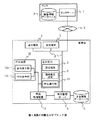
図1は第1実施の形態を示すブロック図である。
【0010】
1は金融機関のセンタに設置されたセンタサーバであり、銀行の支店等の営業店に設置された受付管理サーバ2と専用回線や電話回線等の通信回線3を介して接続し、顧客個人を特定するための識別子(顧客ID(identification)という。)に対応させて、顧客の氏名や家族構成、年齢、性別、職業、顧客の重要度等を示す顧客ランク等の個人情報、顧客の口座の店番号、科目口座番号等の口座情報等を顧客情報として格納する顧客情報データベース4を保有すると共に、金融機関の各営業店の来店履歴をまとめて蓄積する記憶装置を備えている。
【0011】
受付管理サーバ2は、受付端末5で受付けた顧客の来店情報や個人情報等を顧客IDに対応させて蓄積する来店履歴データベース6を保有すると共に、来店した顧客の来店目的等の来店情報や個人情報等を来店順に一覧表で管理する待ち行列管理機能およびその一覧表を後述する応対窓口の情報表示端末9へ表示する情報表示機能等を備えている。
【0012】
受付端末5は、営業店の店頭に設置され、LAN(Local Area Network)7等により受付管理サーバ2と接続しており、応対窓口で取引を行うために来店した顧客が、来店目的等を入力するための表示操作部、顧客のキャッシュカード等の取引カードのカード情報を読取るカード取扱部および受付順に採番された受付番号を印刷した番号札を顧客に発行する番号札発行部等を備えている。
【0013】
8は窓口端末であり、営業店の応対窓口に設置され、応対窓口の担当者(オペレータという。)が顧客との取引を行うために取引科目や取引金額等の取引に必要なデータの表示や入力を行う表示部や入力部、顧客に支払う現金や入金された現金の払出しや収納を行う現金処理部等を備えている。
9は情報表示端末であり、営業店の応対窓口や管理者席に設置され、LAN7を介して受付管理サーバ2と接続しており、受付管理サーバ2が送信した来店した顧客の一覧表を表示する。
【0014】
10は呼出制御装置であり、営業店に設置され、受付管理サーバ2と接続して受付端末5で受付けた顧客の来店目的に応じた応対窓口の決定機能や顧客の受付順に受付番号を採番する受付番号採番機能および顧客の応対窓口への呼出しを行う顧客呼出機能等を備えている。
11は呼出操作部であり、営業店の応対窓口に設置され、呼出制御装置10と接続しており、応対窓口のオペレータが次の顧客と応対の準備が整った時に操作するボタンスイッチ等のスイッチ機能を備えている。
【0015】
12は呼出装置であり、呼出制御装置10と接続して営業店の応対窓口の近傍に設置されており、呼出制御装置10からのデータにより受付番号を電光表示する番号表示部12aと顧客を音声で応対窓口へ誘導する音声呼出部12bで構成されている。
なお、応対窓口が複数存在する場合は、応対窓口毎に情報表示端末9や呼出操作部11、呼出装置12が設置される。
【0016】
本実施の形態の店頭受付システムは、受付管理サーバ2を中心としてこれに接続する来店履歴データベース6と1台または複数の受付端末5および窓口や管理者席に設置された情報表示端末9で構成される受付管理サーバ2が統括する受付管理システムと、呼出制御装置10を中心としてこれに接続する呼出操作部11と呼出装置12で構成される呼出制御装置10が統括する呼出制御システムとを相互にデータ通信可能に接続して構成する。
【0017】
上述した構成の作用について説明する。
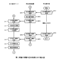
図2は第1実施の形態の受付処理を示す流れ図、図3はその応対処理を示す流れ図である。
まず、図2に示す流れ図を用い、ステップに従って本実施の形態の受付処理について説明する。
【0018】
なお、ステップ名は受付管理サーバ2の場合をSで、受付端末5の場合をSUで、呼出制御装置10の場合をSYで表す。
SU1、受付端末5はその表示操作部の画面に来店目的選択画面を表示して待機している。
来店目的選択画面には、来店目的ボタンの押下を促す旨の文言と「入金」、「出金」、「振込」、「外貨預金」、「新規口座開設」等の各種の取引の来店目的を入力するための来店目的ボタンが表示されている。
【0019】
本実施の形態では、応対窓口で取引を行うために来店した顧客は表示操作部の画面から「外貨預金」を選択し、その来店目的ボタンを押下する。
SU2、これにより顧客の来店目的を認識した受付端末5は、表示操作部の画面に取引カードの挿入を促す画面を表示し、顧客はこれに従って取引カードを受付端末5のカード取扱部に挿入する。
【0020】
この挿入を検知した受付端末5は、カード取扱部によって取引カードの磁気ストライプに記録されているカード情報を読取り、カード情報から顧客の口座の店番号、科目、口座番号等の口座情報を抽出する。
SU3、来店した顧客のカード情報を読取った受付端末5は、抽出した口座情報に来店目的ボタンにより認識した来店目的とそれを顧客が押下した時刻である受付日時を添付して来店情報を作成し、これをLAN7を介して受付管理サーバ2へ送信する。
【0021】
そして、後述するステップSU4で受付管理サーバ2からの受付番号の転送を待つ受付番号受信待ち状態で待機する。
S1、受付端末5からの来店情報の受信を待つ来店情報受信待ち状態で待機していた受付管理サーバ2は、来店情報を受信したことにより新たな顧客の受付けを認識し、これを契機としてステップS2へ移行してステップS3までの割込処理を実行する。
【0022】
S2、顧客の受付けを認識した受付管理サーバ2は、受信した来店情報の口座情報を基にセンタサーバ1と交信して顧客の個人情報の取得を実行する。
すなわち、受付管理サーバ2は顧客の口座情報を添付した個人情報取得依頼を作成し、LAN7を経由して通信回線3を介してセンタサーバ1へ送信する。
個人情報取得依頼を受信したセンタサーバ1は、個人情報取得依頼に添付された口座情報を基に顧客情報データベース4の顧客情報を検索して該当する顧客IDの顧客情報を抽出し、その顧客情報の顧客氏名や年齢、顧客ランク等の個人情報と顧客IDを通信回線3を介して受付管理サーバ2へ送信する。
【0023】
受付管理サーバ2は、通信回線3を介して送信された顧客IDや個人情報をLAN7を経由して受信し、顧客の個人情報を取得する。
この個人情報と来店情報は、履歴情報に書込まれ、受付管理サーバ2の図示しない記憶部に履歴情報の一部として保存される。
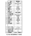
本実施の形態では、図4のb欄からj欄に示す項目の内容、つまり受付日時、顧客の口座の店番号、科目、口座番号、顧客ID、顧客氏名、年齢、顧客ランク、来店目的の内容が履歴情報の一部として書込まれて保存される。
【0024】
S3、これと並行して、受付管理サーバ2は来店した新たな顧客に受付番号を付与するためにその来店目的を添付した受付番号採番依頼を作成し、これを呼出制御装置10へ送信する。
そして、後述するステップS4で呼出制御装置10からの受付番号通知の受信を待つ受付番号通知受信待ち状態で待機する。
【0025】
SY1、受付管理サーバ2からの受付番号採番依頼の受信を待つ受付番号採番依頼受信待ち状態で待機していた呼出制御装置10は、受付番号採番依頼を受信したことにより新たな顧客の受付けを認識し、これを契機としてステップSY2へ移行してステップSY3までの割込処理を実行する。
SY2、受付番号採番依頼を受信した呼出制御装置10は、保存している待ち行列の最後尾の受付番号の次の番号を新たな顧客の受付番号として採番し、添付されている来店目的を採番した受付番号に添付して保存する。
【0026】
SY3、受付番号の採番を終えた呼出制御装置10は、採番した受付番号により受付番号通知を作成し、これを受付管理サーバ2へ送信する。
そして、接続子Dを介して接続する図3に示すステップSAY1で応対窓口の呼出操作部11からの呼出信号の受信を待つ呼出信号受信待ち状態で待機する。
S4、呼出制御装置10からの受付番号通知受信待ち状態で待機していた受付管理サーバ2は、受付番号通知を受信したことを契機としてステップS5へ移行し、ステップS7までの割込処理を実行する。
【0027】
S5、受付管理サーバ2は受信した受付番号通知の受付番号をLAN7を介して受付端末5(ステップSU4)へ転送する。
S6、受付番号の受付端末5への転送を終えた受付管理サーバ2は、受付番号通知により受付番号を作成し、取得した来店情報や個人情報、受付番号等を基に、例えば新たな顧客の来店目的、受付日時、顧客ID、顧客氏名、顧客ランク等を受付番号順に並べて一覧表とするための一覧表情報を作成し、これを保存している一覧表に追加保存して待ち行列を管理すると共に、この一覧表を応対窓口や管理者席の情報表示端末9へ送信してその情報表示端末9へ表示する。
【0028】
これにより、オペレータや管理者は店内の混雑状況の把握や来店した顧客の客層の把握が可能になる。
S7、情報表示端末9への一覧表の表示を終えた受付管理サーバ2は、取得した受付番号を保存している履歴情報に追加して保存する。
本実施の形態では、図4のa欄に示す受付番号が履歴情報に追加される。
【0029】
そして、接続子Bを介して接続する図3に示すステップSA1で呼出制御装置10からの応対開始通知の受信を待つ応対開始通知受信待ち状態で待機する。
SU4、受付管理サーバ2からの受付番号受信待ち状態で待機していた受付端末5は、受付番号を受信したことを契機としてステップSU5へ移行する。
SU5、受付端末5はその表示操作部の画面に番号札の受取りを促す旨の文言を表示し、その番号札発行部によって受信した受付番号を番号札に印刷して顧客に発行する。
【0030】
そして、顧客の番号札の受取りを確認し、次の顧客の受付を行うためにステップSU1へ戻って受付端末5の表示操作部の画面に来店目的選択画面を表示して待機する。
一方、番号札の発行を受けた顧客は、応対窓口からの呼出しを待って待合席等で待機する。
【0031】
以下に、図3に示す流れ図を用い、ステップに従って本実施の形態の応対処理について説明する。
なお、ステップ名は受付管理サーバ2の場合をSAで、呼出制御装置10の場合をSAYで、応対窓口の呼出操作部11場合をSASで表す。
SAS1、応対窓口のオペレータは顧客と応対の準備が整うと、次の顧客を応対窓口へ呼出すために応対窓口に備えられた呼出操作部11のボタンスイッチを押下する。これにより呼出操作部11は応対開始信号を呼出制御装置10へ発信する。
【0032】
SAY1、呼出操作部11からの応対開始信号受信待ち状態で待機していた呼出制御装置10は、応対開始信号を受信したことにより応対窓口での顧客との応対開始を認識し、これを契機としてステップSAY2へ移行してステップSAY3までの割込処理を実行する。
SAY2、応対開始信号の受信した呼出制御装置10は、その信号の発信先により応対窓口の番号とその時刻を認識し、その応対窓口で取扱う取引を参照して受付番号に添付して保存した来店目的を検索して該当する来店目的の待ち行列を抽出し、その待ち行列の先頭の受付番号を読出す。
【0033】
次いで、呼出制御装置10は、認識した応対窓口番号と読出した受付番号とを基に該当する番号札を持つ顧客をその応対窓口へ誘導するための文言を音声データとして生成し、この音声データと受付番号の表示データを該当する応対窓口の呼出装置12へ送信して呼出装置12の番号表示部12aに受付番号の表示データを電光表示すると共に呼出音声部12bにより音声データの音声を発して待機している顧客に応対の準備ができたことを報知する。
【0034】
SAY3、これと並行して、呼出制御装置10は認識した時刻を応対開始日時とし、応対開始日時と応対窓口番号、読出した受付番号により応対開始通知を作成して受付管理サーバ2へ送信し、送信した受付番号を保存している待ち行列から消去する。
そして、後述するステップSAY4で呼出操作部11からの応対終了信号の受信を待つ応対終了信号受信待ち状態で待機する。
【0035】
SA1、呼出制御装置10からの応対開始通知受信待ち状態で待機していた受付管理サーバ2は、応対開始通知を受信したことにより応対窓口での顧客との応対開始を認識し、これを契機としてステップSA2へ移行してステップSA3までの割込処理を実行する。
SA2、応対窓口での顧客との応対開始を認識した受付管理サーバ2は、受信した応対開始通知を基に一覧表の該当する受付番号の一覧表情報を消去して更新し、更新した一覧表を情報表示端末9へ送信して表示されている一覧表を更新する。
【0036】
SA3、一覧表の更新を終えた受付管理サーバ2は、応対開始通知を図示しない記憶部に一時保存する。
そして、後述するステップSA4で呼出制御装置10からの応対終了通知の受信を待つ応対終了通知受信待ち状態で待機する。
SAS2、一方、顧客との取引(本実施の形態では外貨預金)を終えたオペレータは、応対窓口に備えられた呼出操作部11のボタンスイッチを押下する。これにより呼出操作部11は応対終了信号を呼出制御装置10へ発信する。
【0037】
SAY4、呼出操作部11からの応対終了信号受信待ち状態で待機していた呼出制御装置10は、応対終了信号を受信したことにより応対窓口での顧客との応対終了を認識し、これを契機としてステップSAY5へ移行して割込処理を実行する。
SAY5、応対終了信号の受信した呼出制御装置10は、その信号の発信先により応対窓口の番号を認識すると共にその時刻を認識し、認識した時刻を応対終了日時とし、これと応対窓口番号により応対終了通知を作成して受付管理サーバ2へ送信する。
【0038】
そして、接続子Cを介して接続する図2に示すステップSY1で受付管理サーバ2からの受付番号採番依頼受信待ち状態で待機する。
SA4、呼出制御装置10からの応対終了通知受信待ち状態で待機していた受付管理サーバ2は、応対終了通知を受信したことにより応対窓口での顧客との応対終了を認識し、これを契機としてステップSA5へ移行してステップSA6までの割込処理を実行する。
【0039】
SA5、応対窓口での顧客との応対終了を認識した受付管理サーバ2は、受信した受付終了通知の応対窓口番号を基に一時保存した該当する応対窓口の応対開始通知の応対開始日時を読出し、これと受信した応対終了日時とから応対に要した顧客応対時間を算出する。
また、保存している履歴情報の来店情報の受付日時と読出した応対開始日時とから顧客待ち時間を算出し、応対窓口番号と応対開始日時、顧客待ち時間および顧客応対時間により応対情報を作成する。
【0040】
SA6、応対情報の作成を終えた受付管理サーバ2は、この応対情報を保存している履歴情報に追加し、個人情報の顧客IDを基に来店履歴データベース6に蓄積している来店履歴を検索し、該当する顧客の来店履歴がない場合は、新たにその顧客IDによる来店履歴の格納エリアを確保し、応対情報を追加した履歴情報をその顧客の来店履歴として格納する。
【0041】
本実施の形態では、図4のk欄からn欄に示す応対窓口番号、応対開始日時、顧客待ち時間、顧客応対時間が追加され、図4のa欄からn欄に示す項目からなる履歴情報が来店履歴データベース6に格納される。
来店履歴に既に該当する顧客の来店履歴が存在する場合は、応対情報を追加した履歴情報から重複する個人情報に相当する部分を削除し、これをその顧客の来店履歴に加えて格納する。
【0042】
本実施の形態では、図4に示す履歴情報のf欄からi欄の個人情報が削除される。
なお、使用された取引カードが同一の場合は顧客IDに付随したc欄からe欄の口座情報を基にした格納エリアを設け、応対情報を追加した履歴情報から重複する個人情報と口座情報を削除して格納するようにしてもよい。
【0043】
そして、受付管理サーバ2は、保存している履歴情報を消去し、接続子Aを介して接続する図2に示すステップS1で受付端末5から来店情報受信待ち状態で待機する。
このようにして、受付管理サーバ2は上記のステップS1〜S6の一連の処理の流れの中で図4に示すa欄からj欄までの来店情報や個人情報、受付番号を、ステップSA1〜SA5一連の処理の流れの中でk欄からm欄までの応対情報を取得しながら履歴情報を作成し、これを来店履歴データベース6に格納して来店履歴を蓄積する。
【0044】
また、来店履歴データベース6に蓄積された来店履歴は、定期的(例えばその日の終業後)にまたは必要に応じて夜間等の通信回線の混雑時を避けてセンタサーバ1へまとめて送信され、センタサーバ1は各営業店から送られてくる来店履歴を蓄積する。
以上のようにして営業店の来店履歴データベース6に蓄積された来店履歴は、営業店の係員等により定期的にまたは必要に応じて統計処理され、例えばその地域の来店客の曜日や時間帯による来店傾向(客層、来店目的等)や顧客待ち時間との相関関係、来店目的と顧客応対時間との相関関係、応対窓口の稼動効率、来店目的別の需要動向等を分析するための統計情報として作成される。
【0045】
そして、この統計情報を基に応対窓口で取扱う来店目的の変更やオペレータの人選、受付端末5や応対窓口の増減等を行い、営業店の立地に適合したその地域特有の取引体系の構築に活用される。
また、センタにおいては、センタサーバ1に蓄積された来店履歴に基づいて作成された同様の統計情報により金融機関の営業店の統廃合や新規営業店の開設等の金融機関全体の取引体系の構築に活用される。
【0046】
以上説明したように、本実施の形態では、来店した顧客を受付端末で受付け、その顧客の応対を行う一連の流れの中で、順次に履歴情報を保存して来店履歴データベースに蓄積するようにしたことによって、統計処理による調査に必要なデータを容易に収集することができ、統計処理による調査に要する労力や時間を低減することができる。
【0047】
また、受付管理サーバが応対窓口での応対情報を取得して来店履歴に格納するようにしたことによって、顧客の応対に要した時間や待ち時間を蓄積することができ、これを基にした統計情報とすることが可能になり、応対窓口業務の稼動効率を向上することができる。
更に、営業店の来店履歴データベースに来店履歴を集中して格納するようにしたことによって、営業店において容易に来店履歴を活用することができ、その地域に特有の傾向や動向を分析して営業店の業務効率を向上することができると共に、センタサーバへの来店履歴の送信が容易になり、その保守に要する労力や費用を削減することができる。
【0048】
なお、上記の図2に示す受付処理と図3に示す呼出処理は、説明の都合上一連の流れとして説明したが、実際には受付管理サーバや呼出制御装置は常にステップS1、S4、SA1、SA4やステップSY1、SAY1、SAY4で説明したそれぞれの待機状態で割込待機しており、その契機となる信号や送信を受信したときにそれぞれの割込処理を適宜に実行する。
【0049】
また、これらの割込処理は他の受付端末からの受付処理や他の応対窓口の応対処理およびその他の処理との並行処理として実行するようにしてもよい。
更に、受付管理サーバと呼出制御装置は別に設置するとして説明したが、これらの機能を1台の情報処理装置に統合して店頭受付システムを運用するようにしてもよく、営業店の各機器を管理する既存の営業店サーバに上記の受付管理サーバおよび/もしくは呼出制御装置の機能を組込んで運用するようにしてもよい。
【0050】
更に、ステップSAS2において呼出操作部が応対終了信号を送信するとして説明したが、前の顧客との応対が終了し、次の顧客との応対を開始するときの次の応対開始信号の受信を前の応対の応対終了信号および次の応対の応対開始信号として認識するようにしてもよい。
更に、応対窓口や管理者席等に表示した一覧表は、そのオペレータや管理者が必要に応じて任意の顧客を選択し、受付管理サーバがその顧客の家族構成等の個人情報の詳細情報を表示するようにしてもよく、内部または外部のデータベース等からその顧客の個人情報に応じた金融商品等のセールス情報を取得して表示するようにしてもよい。これによりオペレータが事前に応対する顧客に関する種々の情報を把握することができ、より円滑な応対や金融商品の販売を行うことができる。
【0051】
更に、カードを持参していない顧客に対応するために、通帳により応対窓口で取引を行う顧客が通帳のみを持参して来店した場合に備えて顧客の通帳の磁気ストライプに記録されている口座番号等の通帳情報を読取る通帳取扱部を受付端末に設けるようにしてもよく、今まで取引のなかった顧客が新規顧客であることを指示するための「カードなし」ボタンを設けるようにしてもよい。
【0052】
この場合には受付管理サーバは、「カードなし」ボタンが押下された来店情報を受信することによりその顧客を新規顧客と認識し、ステップS2の個人情報の取得は省略して個人情報に新規顧客である旨を記述する。
第2実施の形態例
図5は第2実施の形態を示すブロック図である。
【0053】
なお、上記第1実施の形態例と同様の部分は、同一の符号を付してその説明を省略する。
本実施の形態の来店受付システムの構成は、図1に示す第1実施の形態例の構成と同様であるが、以下の構成が異なる。
21は応対窓口に設置された窓口端末であり、第1実施の形態例の窓口端末8と同様の機能を備える窓口端末であって、LAN7を介して受付管理サーバ2との間で相互にデータ通信可能に接続される。
【0054】
なお、応対窓口に設置される情報表示端末9は、窓口端末21の表示部を利用または専用表示部を増設して窓口端末21に設けるようにしてもよい。
22はATM(Automated Teller Machine)、23はCD(Cash Dispenser)であり、それそれ自動で顧客との間の取引を行う自動取引装置であって、営業店のATMコーナ等に設置され、受付管理サーバ2と接続されている。
【0055】
上記の構成の作用について説明する。
受付端末が受付けた顧客に対する受付処理の作動は、上記第1実施の形態例の作動と同様であるので、その説明を省略する。
なお、本実施の形態の顧客は新規口座を開設するために、「新規口座開設」の来店目的ボタンを押下している。
【0056】
また、受付管理サーバ2には、ステップS2およびS7において図7のa欄からj欄の項目の内容を書込んだ履歴情報が保存されている。
以下に、図6に示す流れ図を用い、ステップに従って本実施の形態の応対処理について説明する。
なお、ステップ名は受付管理サーバ2の場合をSBで、呼出制御装置10の場合をSBYで、応対窓口の場合をSBMで表す。
【0057】
SBM1、応対窓口のオペレータは、顧客と応対の準備が整うと第1実施の形態例のステップSAS1と同様にして呼出操作部11のボタンスイッチを押下し、呼出操作部11は応対開始信号を呼出制御装置10へ発信する。
SBY1、呼出操作部11からの応対開始信号受信待ち状態で待機していた呼出制御装置10は、応対開始信号を受信したことにより応対窓口での顧客との応対開始を認識し、これを契機としてステップSBY2へ移行してステップSBY3までの割込処理を実行する。
【0058】
SBY2、応対開始信号を受信した呼出制御装置10は、第1実施の形態例のステップSAY2と同様にして応対窓口番号と応対開始日時を認識し、その応対窓口で応対する顧客の受付番号を読出し、音声データと受付番号の表示データを該当する応対窓口の呼出装置12へ送信して番号表示部12aと呼出音声部12bにより顧客に応対の準備ができたことを報知する。
【0059】
SBY3、これと並行して、呼出制御装置10は第1実施の形態例のステップSAY3と同様にして応対開始通知を受付管理サーバ2へ送信し、送信した受付番号を保存している待ち行列から消去する。
そして、接続子Cを介して接続する図2に示すステップSY1で受付管理サーバ2からの受付番号採番依頼受信待ち状態で待機する。
【0060】
SB1、呼出制御装置10からの応対開始通知受信待ち状態で待機していた受付管理サーバ2は、応対開始通知を受信したことにより応対窓口での顧客との応対開始を認識し、これを契機としてステップSB2へ移行してステップSB4までの割込処理を実行する。
SB2、応対窓口での顧客との応対開始を認識した受付管理サーバ2は、第1実施の形態例のステップSA2と同様にして該当する受付番号の一覧表情報を消去し、情報表示端末9に表示されている一覧表を更新する。
【0061】
SB3、これと並行して、受付管理サーバ2は消去した受付番号、つまりその応対窓口で新たに取引を行う顧客の受付番号の来店情報や個人情報を受付処理時にステップS7で保存した履歴情報から読出し、これを受付情報としてLAN7を介して該当する応対窓口の窓口端末21へ送信する。
本実施の形態では、図7のa欄からj欄に示す受付番号、受付日時、顧客の口座の店番号、科目、口座番号、顧客ID、顧客氏名、年齢、顧客ランク、来店目的からなる受付情報が窓口端末21へ送信される。
【0062】
SB4、一覧表の更新および受付情報の窓口端末21への送信を終えた受付管理サーバ2は、応対開始通知を図示しない記憶部に一時保存する。
そして、後述するステップSB5で窓口端末21からの取引情報の受信を待つ取引情報受信待ち状態で待機する。
SBM2、窓口端末21は受付管理サーバ2からの受付情報を受信する。
【0063】
SBM3、受付情報を受信した窓口端末21は、受付情報の受付番号をその表示部の画面に表示すると共に受付情報の個人情報を基に取引に必要な顧客の口座番号等の入力データを自動的に生成する。これによりオペレータの入力負荷が軽減される。
SBM4、オペレータは、窓口端末21によって顧客との取引(本実施の形態では定期預金と外貨定期の2つの新規口座の開設)を行い、取引に必要なデータを窓口端末21の入力部から入力する。
【0064】
この時、顧客の氏名等の入力データは自動生成されたデータがその取引の入力画面に自動的に表示される。
オペレータは、顧客との取引が終了すると、顧客との応対中に得た感触、例えば住宅の購入や子供の入学あるいは投資への興味等の応対時の感触情報を文字により窓口端末21の入力部から入力し、窓口端末21により取引の終了操作を行う。
【0065】
この終了操作により取引の終了を認識した窓口端末21は、一または複数の取引の取引科目やその取引金額およびその適用、例えば契約期間や課税の種別等の取引内容およびオペレータの氏名とオペレータID、応対窓口番号、オペレータが入力した一または複数の文言による感触情報により取引情報を作成し、これをLAN7を介して受付管理サーバ2へ送信する。
【0066】
本実施の形態では、定期預金と外貨定期のそれぞれの取引内容とオペレータID、オペレータ氏名、応対窓口番号および感触情報(「住宅ローン興味有り」等の文言)からなる取引情報が送信される。
なお、感触情報の入力は、上記の文字入力に限らず、選択番号と定型化された感触情報を表示して選択番号により選択するようにしてもよく、アンケート形式によりオペレータが項目を選択するようにしてもよい。これにより統一的な感触情報の収集が可能になる。
【0067】
そして、窓口端末21は次の顧客との取引が開始されるまでその表示部に窓口業務選択画面等の初期画面を表示して待機する。
SB5、窓口端末21からの取引情報受信待ち状態で待機していた受付管理サーバ2は、取引情報を受信したことにより応対窓口での顧客との応対終了を認識し、これを契機としてステップSB6へ移行してステップSB7までの割込処理を実行する。
【0068】
SB6、応対窓口での顧客との応対終了を認識した受付管理サーバ2は、取引情報を受信した時刻を応対終了日時と認識し、取引情報の応対窓口番号を基に一時保存した該当する応対窓口の応対開始通知の応対開始日時を読出し、これと認識した応対終了日時とから応対に要した顧客応対時間を算出する。
また、保存している履歴情報の来店情報の受付日時と読出した応対開始日時とから顧客待ち時間を算出し、応対開始日時と応対終了日時、顧客待ち時間、顧客応対時間および取引情報により応対情報を作成する。
【0069】
SB7、応対情報の作成を終えた受付管理サーバ2は、第1実施の形態例のステップSA6と同様にしてこの応対情報を保存している履歴情報に追加し、顧客IDを基に応対情報を追加した履歴情報を来店履歴データベース6の顧客の来店履歴に格納する。
本実施の形態では図7のk欄、l欄に示す応対窓口番号、応対開始日時、m1欄からm4欄に示す定期預金の取引内容、n1欄からn4欄に示す外貨定期の取引内容およびu欄からz欄に示すオペレータID、オペレータ氏名、顧客待ち時間、顧客応対時間および感触情報が追加され、図7のa欄からz欄に示す項目からなる履歴情報が来店履歴データベース6に格納される。
【0070】
そして、受付管理サーバ2は、保存している履歴情報を消去し、接続子Aを介して接続する図2に示すステップS1で受付端末5から来店情報受信待ち状態で待機する。
なお、取引内容の格納領域は顧客が多数の取引を同時に行うことを考慮して多くの領域を確保しておくことが望ましい。
【0071】
このように、本実施の形態の受付管理サーバ2は、第1実施の形態例と同様にしてその一連の処理の流れの中で来店情報や個人情報、受付番号、応対情報を取得しながら履歴情報を作成し、これを来店履歴データベース6に格納して来店履歴を蓄積する。
また、受付管理サーバ2は、自動取引装置からも以下のようにして来店履歴を蓄積する。
【0072】
自動取引装置による来店履歴の蓄積は、ATM22、CD23どちらの場合であっても同様であるので、ATM22の場合を例に説明する。
顧客がATM22を利用して取引を行う場合、ATM22はその取引の過程で顧客の取引カードまたは通帳に記録されている顧客の口座情報を読取る。
この時、ATM22はこの口座情報を第1実施の形態例の受付端末5のステップSU3と同様に来店情報を受付管理サーバ2へ送信する。
【0073】
この場合に、来店情報の来店目的と受付日時は、顧客が取引選択画面から選択した取引、例えば出金取引とその取引選択ボタンを押下した時刻として送信される(以下に記載する各情報において、第1および上記の実施の形態例と異なる履歴情報の内容は、後述する履歴情報の説明の中でまとめて説明する)。
このATM22からの来店情報を受信した受付管理サーバ2は、第1実施の形態例のステップS2と同様にしてセンタサーバ1から個人情報を取得し、個人情報と来店情報を履歴情報の一部として保存する。
【0074】
そして、ATM22は顧客との取引が終了すると上記の窓口端末21のステップSBM4と同様の取引情報を受付管理サーバ2へ送信する。
これを受信した受付管理サーバ2は、上記のステップSB6、SB7と同様に応対情報を作成し、図7に示す履歴情報と同様の履歴情報を来店履歴データベース6に格納する。
【0075】
この場合に、履歴情報はa欄の受付番号は空欄、b欄の受付日時は前述の顧客が取引選択ボタンを押下した時刻、j欄の来店目的は前述の顧客が選択した取引選択ボタンの内容(本例では出金取引)、k欄の応対窓口番号は顧客との取引を行ったATM22(またはCD23)の識別番号、l欄の応対開始時刻はb欄と同じ日時、m1欄〜m4欄の取引内容は顧客が行った取引の内容(本例では取引科目1は出金取引、適用1−1、適用1−2は空欄または金種指定があった場合はその内容、取引金額は引出金額)、n1欄〜n4欄は空欄または複数の取引があった場合はその取引内容、u欄のオペレータIDはk欄と同じ識別番号、v欄のオペレータ氏名は空欄、w欄の応対終了日時は受付管理サーバがATM22からの取引情報を受信した時刻、x欄の顧客待ち時間は「0」、y欄の顧客応対時間はw欄の日時からl欄の日時を減算した時間、z欄の感触情報は空欄、その他の欄は上記図7の場合と同様として格納される。
【0076】
このように、本実施の形態の受付管理サーバ2は、ATM22やCD23からも取引情報等を取得して履歴情報を作成し、これを来店履歴データベース6に格納して来店履歴を蓄積する。
また、来店履歴データベース6に蓄積された来店履歴は、第1実施の形態例と同様にしてセンタサーバ1へ送信され、センタサーバ1は各営業店から送られてくる来店履歴を蓄積する。
【0077】
なお、来店履歴情報の蓄積は、上記のATM22やCD23に限らず、無人契約機等の自動取引装置を受付管理サーバ2に接続し、ATM22等と同様にして上記した来店履歴情報に加えて蓄積するようにしてもよい。
以上のようにして営業店の来店履歴データベース6やセンタサーバ1に蓄積された来店履歴は、第1実施の形態例と同様に営業店やセンタにおいてこれに基づいた統計情報が作成され、その地域や金融機関全体の取引体系の構築に活用される。
【0078】
また、本実施の形態では来店履歴に窓口端末21やATM22等の取引情報が格納されており、例えば顧客の年齢や職業と購入する金融商品やその金額との相関関係、自動取引装置の取引内容と応対時間の相関関係、自動取引装置の出金取引の引出金額等の頻度分布等の統計情報の作成が可能になる。
更に、付加価値として、営業店全体の稼働率を統計して分析することにより人員や機器の適切な配置計画が策定可能となると共に、オペレータ等の業務効率やセールス実績等の統計により査定考査にも利用可能になる。
【0079】
以上説明したように、本実施の形態では、第1実施の形態例の効果に加えて、窓口端末や自動取引装置からの取引情報を自動的に取得して来店履歴に加えて蓄積し、これにより統計情報を作成するようにしたことによって、人員や機器の適切な配置計画が策定できると共にオペレータ等の査定考査にも利用することができる。
【0080】
【発明の効果】
以上述べたように、本発明は、来店した顧客を受付端末で受付け、その顧客の応対を行う一連の流れの中で、順次に履歴情報を保存して来店履歴データベースに蓄積するようにしたことによって、統計処理による調査に必要なデータを容易に収集することができ、統計処理による調査に要する労力や時間を低減することができるという効果が得られる。
【0081】
また、受付管理サーバが応対窓口での応対情報を取得して来店履歴に格納するようにしたことによって、顧客の応対に要した時間や待ち時間を蓄積することができ、これを基にした統計情報とすることが可能になり、応対窓口業務の稼動効率を向上することができる。
【図面の簡単な説明】
【図1】第1実施の形態を示すブロック図
【図2】第1実施の形態の受付処理を示す流れ図
【図3】第1実施の形態の応対処理を示す流れ図
【図4】第1実施の形態の履歴情報を示す説明図
【図5】第2実施の形態を示すブロック図
【図6】第2実施の形態の応対処理を示す流れ図
【図7】第2実施の形態の履歴情報を示す説明図
【符号の説明】
1 センタサーバ
2 受付管理サーバ
3 通信回線
4 顧客情報データベース
5 受付端末
6 来店履歴データベース
7 LAN
8、21 窓口端末
9 情報表示端末
10 呼出制御装置
11 呼出操作部
12 呼出装置
12a 番号表示部
12b 呼出音声部
22 ATM
23 CD[0001]
TECHNICAL FIELD OF THE INVENTION
The present invention relates to an over-the-counter reception system that is installed in a sales office such as a financial institution or a travel agency and manages the reception order of customers, a reception management server and a program thereof, and a method of utilizing a store visit history accumulated thereby.
[0002]
[Prior art]
Conventional in-store reception systems installed in banks are based on the customer's card information entered into the reception terminal and input information such as the purpose of visiting the store, such as whether or not to open an account at the bank, the creditworthiness of the customer, past transaction status, etc. Performs ordering processing that differentiates customers of own and other banks based on customer confirmation information, displays customer confirmation information and sales information at the reception counter, conducts transactions with customers, and inputs customer information and decision order information, etc. The customer guidance information is cumulatively recorded in the storage means, and the appropriate personnel and appropriate services are confirmed by statistical analysis based on the information (for example, see Patent Document 1).
[0003]
[Patent Document 1]
[Problems to be solved by the invention]
However, in the conventional technology described above, since the card information of the customer, the input information such as the purpose of visiting the store, the determination order information, and the like are cumulatively recorded in the storage means, the tendency of the visitor to the store by the statistical processing, the customer and the product Insufficient information such as customer name and family structure, gender, age, occupation, and other personal information necessary to statistically analyze the correlations, market trends, etc. When conducting a trend survey, correlation survey, or trend survey expected by financial institutions, etc., the personal information and response information obtained for each customer of the recorded input information are acquired from other databases, and data is collected. There is a problem that it is necessary to perform the analysis by the statistical processing, and the investigation by the statistical processing requires a great deal of labor and time.
[0005]
The present invention has been made to solve the above problems, and has as its object to provide means for easily collecting data required for an investigation by statistical processing.
[0006]
[Means for Solving the Problems]
In order to solve the above problems, the present invention provides a storefront reception system including a reception terminal that issues a number tag to a customer who has visited for a transaction at a reception counter, and a reception management server connected to the reception terminal. The reception management server acquires the visit information input at the reception terminal and the reception information at the reception window, and accumulates them as a visit history.
[0007]
A reception management server connected to a center server that manages the customer information and a reception terminal that issues a number tag to the customer; a customer reception recognition step of receiving the store visit information from the reception terminal and recognizing the reception of the customer; A personal information acquisition step of acquiring the customer's personal information from the center server when recognizing the reception of the customer; a reception information acquisition step of acquiring reception information at the reception counter; A visit history accumulation step of accumulating information and response information as a visit history.
[0008]
Furthermore, the present invention is characterized in that statistical information is created based on the customer visit history accumulated by the above-mentioned store reception system, and the statistical information is used for constructing a transaction system.
[0009]
BEST MODE FOR CARRYING OUT THE INVENTION
An embodiment of a storefront reception system according to the present invention will be described below with reference to the drawings.
Example of the first embodiment
FIG. 1 is a block diagram showing the first embodiment.
[0010]
[0011]
The
[0012]
The
[0013]
[0014]
[0015]
Numeral 12 denotes a calling device, which is connected to the
When there are a plurality of reception counters, the
[0016]
The over-the-counter reception system according to the present embodiment includes a reception history database 6 connected to the
[0017]
The operation of the above configuration will be described.
FIG. 2 is a flowchart showing the reception process of the first embodiment, and FIG. 3 is a flowchart showing the response process.
First, the reception process of the present embodiment will be described according to the steps using the flowchart shown in FIG.
[0018]
The step name is S for the
The
On the visit purpose selection screen, the words that prompt the user to press the visit purpose button and the purpose of visiting various transactions such as “deposit”, “withdrawal”, “transfer”, “foreign currency deposit”, “open new account”, etc. A visit purpose button for inputting is displayed.
[0019]
In the present embodiment, a customer who visits the store to conduct a transaction at the reception counter selects "foreign currency deposit" from the screen of the display operation unit, and presses the visit purpose button.
SU2, the
[0020]
The
SU 3, the
[0021]
Then, in step SU4 described later, the process stands by in a reception number reception waiting state of waiting for the transfer of the reception number from the
S1, the
[0022]
S2, the
That is, the
The
[0023]
The
The personal information and the visit information are written in the history information and stored in a storage unit (not shown) of the
In the present embodiment, the contents of the items shown in columns b to j of FIG. 4, that is, the reception date and time, the store number of the customer's account, the subject, the account number, the customer ID, the customer's name, the age, the customer rank, The contents are written and saved as part of the history information.
[0024]
S <b> 3, in parallel with this, the
Then, in step S4 described later, the process stands by in a reception number notification reception waiting state of waiting for reception of a reception number notification from the
[0025]
SY1, the
SY2, the
[0026]
SY3, the
Then, in step SAY1 shown in FIG. 3 for connection via the connector D, the apparatus stands by in a call signal reception waiting state of waiting for reception of a call signal from the
S4, the
[0027]
S5, the
S6, the
[0028]
As a result, the operator and the manager can grasp the congestion state in the store and the customer class of the visiting customers.
S7, the
In the present embodiment, the reception number shown in the column a of FIG. 4 is added to the history information.
[0029]
Then, in step SA1 shown in FIG. 3 for connection via the connector B, the system waits in a state of waiting for reception of a response start notification from the
SU4, the
The
[0030]
Then, the reception of the number tag of the customer is confirmed, and the process returns to step SU1 to display the visiting purpose selection screen on the screen of the display operation unit of the
On the other hand, the customer who has received the number tag waits at a waiting seat or the like waiting for a call from the reception desk.
[0031]
Hereinafter, the response processing according to the present embodiment will be described according to the steps using the flowchart shown in FIG.
The step name is represented by SA for the
When the operator of the reception desk is ready for reception with the customer, the operator presses the button switch of the
[0032]
SAY1, the
SAY2, the
[0033]
Next, the
[0034]
SAY3, in parallel with this, the
Then, in step SAY4 described later, the process stands by in a state of waiting for the reception of a response end signal from the
[0035]
SA1, the
SA2, the
[0036]
SA3, the
Then, in step SA4 described later, the process stands by in a state of waiting for reception of a response end notification from the
On the other hand, the operator who has finished the transaction with the customer (foreign currency deposit in this embodiment) presses the button switch of the
[0037]
SAY4, the
SAY5, the
[0038]
Then, in a step SY1 shown in FIG. 2 for connection via the connector C, the apparatus stands by in a state of waiting for a reception numbering request from the
SA4, the
[0039]
SA5, the
Also, the customer waiting time is calculated from the reception date and time of the store information of the stored history information and the read response start date and time, and the response information is created based on the reception window number, the response start date and time, the customer wait time and the customer response time. .
[0040]
SA6, the
[0041]
In the present embodiment, the service contact number, the service start date and time, the customer waiting time, and the customer service time shown in columns k to n of FIG. 4 are added, and history information including items shown in columns a to n of FIG. Is stored in the store visit history database 6.
If the visit history of the customer corresponding to the visit history already exists, the part corresponding to the duplicated personal information is deleted from the history information to which the response information is added, and this is stored in addition to the visit history of the customer.
[0042]
In the present embodiment, the personal information in column i is deleted from column f in the history information shown in FIG.
If the transaction card used is the same, a storage area based on the account information in columns c to e attached to the customer ID is provided, and duplicate personal information and account information are added from the history information to which the response information is added. You may make it delete and store.
[0043]
Then, the
In this way, the
[0044]
The visit history stored in the visit history database 6 is transmitted to the
The store visit history accumulated in the store visit history database 6 as described above is subjected to statistical processing periodically or as needed by a store attendant or the like, for example, according to the day of the week or the time zone of the store visitor in the region. As statistical information for analyzing the tendency of visiting customers (customer segment, purpose of visiting, etc.) and the waiting time of customers, the correlation between the purpose of visiting and customer response time, the operation efficiency of the service counter, the demand trend by the purpose of visiting the store, etc. Created.
[0045]
Based on this statistical information, we change the purpose of visits handled at the reception desk, select operators, increase or decrease the number of
Further, in the center, similar statistical information created based on the store visit history accumulated in the
[0046]
As described above, in the present embodiment, in a series of flows in which a customer who has visited the store is received by the reception terminal and the customer is dealt with, history information is sequentially stored and stored in the store history database. This makes it possible to easily collect data necessary for the investigation by the statistical processing, and reduce the labor and time required for the investigation by the statistical processing.
[0047]
In addition, the reception management server acquires the reception information at the reception desk and stores it in the store visit history, so that the time and waiting time required for customer reception can be accumulated, and statistics based on this can be accumulated. It becomes possible to use the information, and it is possible to improve the operation efficiency of the reception service.
Furthermore, since the store visit history is centrally stored in the store visit history database, the store visit history can be easily utilized in the store, and the trends and trends peculiar to the region are analyzed to analyze the store visit history. The business efficiency of the store can be improved, the transmission of the visit history to the center server can be easily performed, and the labor and cost required for the maintenance can be reduced.
[0048]
Note that the above-described reception process shown in FIG. 2 and the calling process shown in FIG. 3 have been described as a series of flows for convenience of explanation. However, actually, the reception management server and the call control device always perform steps S1, S4, SA1, In the standby state described in SA4 and steps SY1, SAY1, and SAY4, an interrupt is awaited. When a signal or transmission triggering the interruption is received, the respective interrupt processing is appropriately executed.
[0049]
In addition, these interrupt processes may be executed as a parallel process with a reception process from another reception terminal, a reception process at another reception window, and other processes.
Furthermore, although the reception management server and the call control device have been described as being separately installed, these functions may be integrated into one information processing device to operate the storefront reception system. The functions of the reception management server and / or the call control device described above may be incorporated into an existing branch server to be managed and operated.
[0050]
Further, in step SAS2, it has been described that the call operation unit transmits the response end signal. However, the reception with the previous customer is completed, and the reception of the next response start signal when starting the response with the next customer is performed. May be recognized as a response end signal of the first response and a response start signal of the next response.
Further, in the list displayed at the reception desk or the administrator's seat, the operator or the administrator selects an arbitrary customer as necessary, and the reception management server displays detailed information of the personal information such as the family structure of the customer. The information may be displayed, or sales information such as financial products corresponding to the personal information of the customer may be acquired from an internal or external database or the like and displayed. As a result, the operator can grasp in advance various kinds of information about the customers who are responding, and can more smoothly respond and sell financial products.
[0051]
Furthermore, in order to correspond to a customer who does not bring a card, the account number recorded on the magnetic stripe of the customer's passbook in case the customer who makes a transaction at the reception counter with a passbook comes to the store with only the passbook A passbook handling unit for reading passbook information, such as the like, may be provided in the reception terminal, or a “no card” button for indicating that a customer who has not made a transaction so far is a new customer may be provided. .
[0052]
In this case, the reception management server recognizes the customer as a new customer by receiving the visit information for which the “No card” button is pressed, and omits the acquisition of the personal information in step S2 and replaces the personal information with the new customer. Is described.
Example of the second embodiment
FIG. 5 is a block diagram showing the second embodiment.
[0053]
The same parts as those in the first embodiment are denoted by the same reference numerals, and description thereof will be omitted.
The configuration of the store visit reception system of the present embodiment is the same as the configuration of the first embodiment shown in FIG. 1, but differs in the following configuration.
Reference numeral 21 denotes a window terminal installed at the reception window, which has the same function as the
[0054]
The
[0055]
The operation of the above configuration will be described.
The operation of the reception process for the customer accepted by the reception terminal is the same as the operation of the first embodiment, and the description thereof will be omitted.
Note that the customer in the present embodiment has pressed the "new account opening" visit purpose button to open a new account.
[0056]
Further, the
Hereinafter, the response processing according to the present embodiment will be described according to the steps using the flowchart shown in FIG.
The step name is represented by SB for the
[0057]
When the SBM1 and the reception desk operator are ready to receive the customer, the operator presses the button switch of the
SBY1, the
[0058]
SBY2, the
[0059]
SBY3, in parallel with this, the
Then, in a step SY1 shown in FIG. 2 for connection via the connector C, the apparatus stands by in a state of waiting for a reception numbering request from the
[0060]
SB1, the
SB2, the
[0061]
SB3, in parallel with this, the
In the present embodiment, the reception numbers shown in columns a to j of FIG. 7 include reception numbers, reception dates and times, store numbers of accounts of customers, accounts, account numbers, customer IDs, customer names, ages, customer ranks, and visit purposes. The information is transmitted to the counter terminal 21.
[0062]
SB4, the
Then, in step SB5 described later, the system waits in a transaction information reception waiting state of waiting for reception of transaction information from the counter terminal 21.
The
[0063]
SBM3, the counter terminal 21 receiving the reception information, displays the reception number of the reception information on the screen of the display unit, and automatically inputs the customer's account number and the like necessary for the transaction based on the personal information of the reception information. To be generated. Thereby, the input load of the operator is reduced.
The
[0064]
At this time, input data such as the name of the customer is automatically generated, and the automatically generated data is automatically displayed on the input screen of the transaction.
When the operator has completed the transaction with the customer, the operator obtains the feeling obtained during the reception with the customer, for example, the feeling information at the time of reception, such as the purchase of a house, the entrance of a child, or an interest in investment, etc., by using an input unit of the counter terminal 21 in characters. , And an operation for ending the transaction is performed by the counter terminal 21.
[0065]
The contact terminal 21 that recognizes the end of the transaction by this end operation, the transaction item of one or a plurality of transactions, the transaction amount and its application, for example, the transaction contents such as the contract period and taxation type, the operator's name and operator ID, The transaction information is created based on the response window number and the touch information based on one or more words input by the operator, and the transaction information is transmitted to the
[0066]
In the present embodiment, transaction information including the transaction contents of the term deposit and the foreign currency term, and the operator ID, the operator's name, the reception counter number, and the touch information (text such as “I am interested in a mortgage loan”) are transmitted.
The input of the touch information is not limited to the above-described character input, and the selection information and the stylized touch information may be displayed and selected by the selection number, and the operator may select the item in a questionnaire format. It may be. This makes it possible to collect unified feel information.
[0067]
Then, the counter terminal 21 displays an initial screen such as a counter job selection screen on its display unit and waits until a transaction with the next customer is started.
SB5, the
[0068]
SB6, the
Also, the customer waiting time is calculated from the reception date and time of the visit information of the stored history information and the read reception start date and time, and the reception information is obtained from the reception start date and time, the reception end date and time, the customer wait time, the customer reception time and the transaction information. Create
[0069]
SB7, the
In the present embodiment, the reception contact number, the reception start date and time, the transaction contents of the time deposit shown in the columns m1 to m4, the transaction contents of the foreign currency period shown in the columns n1 to n4, and u The operator ID, the operator's name, the customer waiting time, the customer response time, and the touch information shown in the columns z to z are added, and the history information including the items shown in the columns a to z in FIG. .
[0070]
Then, the
In addition, it is desirable to secure a large number of storage areas for transaction contents in consideration of the fact that a customer performs many transactions at the same time.
[0071]
As described above, the
The
[0072]
The accumulation of the visit history by the automatic transaction apparatus is the same regardless of the case of the
When a customer makes a transaction using the
At this time, the
[0073]
In this case, the visit purpose and the reception date and time of the visit information are transmitted as the transaction selected by the customer from the transaction selection screen, for example, the withdrawal transaction and the time at which the transaction selection button is pressed (in each information described below, The contents of the history information different from those of the first and the above-described embodiments will be collectively described in the description of the history information described later).
The
[0074]
Then, when the transaction with the customer is completed, the
The
[0075]
In this case, in the history information, the reception number in column a is blank, the reception date in column b is the time when the customer pressed the transaction selection button, and the purpose of visiting the column j is the content of the transaction selection button selected by the customer. (In this example, withdrawal transaction), the reception window number in the k column is the identification number of the ATM 22 (or CD23) that has transacted with the customer, the reception start time in the l column is the same date and time as the b column, and the m1 to m4 columns. Is the content of the transaction made by the customer (in this example,
[0076]
As described above, the
The store visit history stored in the store visit history database 6 is transmitted to the
[0077]
The accumulation of the visit history information is not limited to the
As described above, the store visit history stored in the store visit history database 6 and the
[0078]
Further, in the present embodiment, transaction information of the counter terminal 21 and the
Furthermore, as an added value, by statistically analyzing the occupancy rate of the entire branch, it is possible to formulate an appropriate allocation plan for personnel and equipment, and to conduct assessments and assessments based on statistics such as the operational efficiency of operators and sales performance. Will also be available.
[0079]
As described above, in the present embodiment, in addition to the effects of the first embodiment, the transaction information from the teller terminal or the automatic transaction device is automatically acquired and stored in addition to the store visit history. By creating statistical information, an appropriate arrangement plan of personnel and equipment can be formulated, and the information can be used for assessment and evaluation by an operator or the like.
[0080]
【The invention's effect】
As described above, according to the present invention, history information is sequentially stored and stored in the visit history database in a series of flows in which a customer who visits the store is received by the reception terminal and the customer is handled. Thereby, the data required for the investigation by the statistical processing can be easily collected, and the effect of reducing the labor and time required for the investigation by the statistical processing can be obtained.
[0081]
In addition, the reception management server acquires the reception information at the reception desk and stores it in the store visit history, so that the time and waiting time required for customer reception can be accumulated, and statistics based on this can be accumulated. It becomes possible to use the information, and it is possible to improve the operation efficiency of the reception service.
[Brief description of the drawings]
FIG. 1 is a block diagram showing a first embodiment.
FIG. 2 is a flowchart illustrating a reception process according to the first embodiment;
FIG. 3 is a flowchart showing a response process according to the first embodiment;
FIG. 4 is an explanatory diagram showing history information according to the first embodiment;
FIG. 5 is a block diagram showing a second embodiment.
FIG. 6 is a flowchart showing a response process according to the second embodiment;
FIG. 7 is an explanatory diagram showing history information according to the second embodiment;
[Explanation of symbols]
1 center server
2 reception management server
3 Communication line
4 Customer information database
5 reception terminal
6 visit history database
7 LAN
8,21 Counter terminal
9 Information display terminal
10 Call control device
11 Call operation section
12 calling device
12a Number display section
12b Call voice part
22 ATM
23 CD
Claims (8)
前記受付管理サーバが、前記受付端末で入力された来店情報と、前記応対窓口での応対情報とを取得し、これらを来店履歴として蓄積することを特徴とする店頭受付システム。A reception terminal for issuing a number tag to a customer who has come to the store for a transaction at the reception counter, and a reception management server connected to the reception terminal,
A storefront reception system, wherein the reception management server acquires the store visit information input at the reception terminal and the reception information at the reception window, and accumulates them as a store visit history.
顧客情報を管理するセンタサーバを設け、該センターサーバに前記受付管理サーバを接続し、前記受付管理サーバが顧客の来店を認識したときに、前記センタサーバから前記顧客の個人情報を取得し、該個人情報を来店履歴として蓄積することを特徴とする店頭受付システム。In claim 1,
A center server for managing customer information is provided, the reception management server is connected to the center server, and when the reception management server recognizes the visit of the customer, the personal information of the customer is obtained from the center server, A storefront reception system that stores personal information as store visit history.
前記応対窓口に前記受付管理サーバと接続する窓口端末を設け、前記受付管理サーバが、前記応対情報を前記窓口端末から取得することを特徴とする店頭受付システム。In claim 1 or claim 2,
A counter terminal connected to the reception management server is provided at the reception counter, and the reception management server acquires the reception information from the counter terminal.
顧客との取引を自動で行う自動取引装置を設け、該自動取引装置を前記受付管理サーバに接続し、前記自動取引装置が顧客との取引を行ったときに、前記受付管理サーバが、その取引の取引情報を取得することを特徴とする店頭受付システム。In claim 1, claim 2, or claim 3,
An automatic transaction device for automatically performing a transaction with a customer is provided, the automatic transaction device is connected to the reception management server, and when the automatic transaction device performs a transaction with the customer, the reception management server performs the transaction with the customer. In-store reception system characterized by acquiring transaction information of a store.
前記受付端末での顧客の受付けを認識したときに、前記センタサーバから前記顧客の個人情報を取得し、該個人情報と、前記受付端末からの来店情報と、前記応対窓口からの応対情報とを来店履歴として蓄積することを特徴とする受付管理サーバ。Connect to a center server that manages customer information and a reception terminal that issues a number tag to customers who come to the store for dealings at the reception counter,
When recognizing the acceptance of the customer at the reception terminal, the personal information of the customer is acquired from the center server, and the personal information, the visit information from the reception terminal, and the reception information from the reception window are obtained. A reception management server characterized by storing as visit history.
前記応対窓口に窓口端末を設け、該窓口端末に接続し、前記応対情報を前記窓口端末から取得することを特徴とする受付管理サーバ。In claim 5,
A reception management server, wherein a counter terminal is provided at the reception counter, the reception terminal is connected to the counter terminal, and the reception information is acquired from the counter terminal.
前記受付端末からの来店情報を受信して顧客の受付けを認識する顧客受付認識ステップと、
顧客の受付を認識したときに、前記センタサーバから前記顧客の個人情報を取得する個人情報取得ステップと、
前記応対窓口での応対情報を取得する応対情報取得ステップと、
前記来店情報と個人情報と応対情報とを来店履歴として蓄積する来店履歴蓄積ステップとを実行させることを特徴とする受付管理サーバのプログラム。A center server that manages customer information and a reception management server that connects to a reception terminal that issues number tags to customers,
A customer reception recognition step of receiving the visit information from the reception terminal and recognizing the reception of the customer,
When recognizing the reception of the customer, a personal information obtaining step of obtaining the personal information of the customer from the center server,
Reception information obtaining step of obtaining reception information at the reception window,
A store visit history storing step of storing the store visit information, personal information, and response information as a store visit history.
Priority Applications (1)
| Application Number | Priority Date | Filing Date | Title |
|---|---|---|---|
| JP2003055713A JP2004265200A (en) | 2003-03-03 | 2003-03-03 | Shop reception system and its reception management server, its program and utilizing method of visit history accumulated thereby |
Applications Claiming Priority (1)
| Application Number | Priority Date | Filing Date | Title |
|---|---|---|---|
| JP2003055713A JP2004265200A (en) | 2003-03-03 | 2003-03-03 | Shop reception system and its reception management server, its program and utilizing method of visit history accumulated thereby |
Publications (1)
| Publication Number | Publication Date |
|---|---|
| JP2004265200A true JP2004265200A (en) | 2004-09-24 |
Family
ID=33119642
Family Applications (1)
| Application Number | Title | Priority Date | Filing Date |
|---|---|---|---|
| JP2003055713A Pending JP2004265200A (en) | 2003-03-03 | 2003-03-03 | Shop reception system and its reception management server, its program and utilizing method of visit history accumulated thereby |
Country Status (1)
| Country | Link |
|---|---|
| JP (1) | JP2004265200A (en) |
Cited By (5)
| Publication number | Priority date | Publication date | Assignee | Title |
|---|---|---|---|---|
| JP2006330957A (en) * | 2005-05-25 | 2006-12-07 | Oki Electric Ind Co Ltd | Identification system |
| JP2009086717A (en) * | 2007-09-27 | 2009-04-23 | Oki Electric Ind Co Ltd | Over-the-counter customer service processing system |
| JP2010044575A (en) * | 2008-08-12 | 2010-02-25 | Mizuho Bank Ltd | Customer guiding system, customer guiding method, and customer guiding program |
| JP6101372B1 (en) * | 2016-01-26 | 2017-03-22 | 株式会社リクルートホールディングス | Order management system, order management terminal, and order management program |
| JP6126261B1 (en) * | 2016-03-23 | 2017-05-10 | 株式会社リクルートホールディングス | System, method and program for supporting responders |
-
2003
- 2003-03-03 JP JP2003055713A patent/JP2004265200A/en active Pending
Cited By (7)
| Publication number | Priority date | Publication date | Assignee | Title |
|---|---|---|---|---|
| JP2006330957A (en) * | 2005-05-25 | 2006-12-07 | Oki Electric Ind Co Ltd | Identification system |
| JP2009086717A (en) * | 2007-09-27 | 2009-04-23 | Oki Electric Ind Co Ltd | Over-the-counter customer service processing system |
| JP2010044575A (en) * | 2008-08-12 | 2010-02-25 | Mizuho Bank Ltd | Customer guiding system, customer guiding method, and customer guiding program |
| JP6101372B1 (en) * | 2016-01-26 | 2017-03-22 | 株式会社リクルートホールディングス | Order management system, order management terminal, and order management program |
| JP2017134489A (en) * | 2016-01-26 | 2017-08-03 | 株式会社リクルートホールディングス | Order management system, order management terminal, and order management program |
| JP6126261B1 (en) * | 2016-03-23 | 2017-05-10 | 株式会社リクルートホールディングス | System, method and program for supporting responders |
| JP2017174097A (en) * | 2016-03-23 | 2017-09-28 | 株式会社リクルートホールディングス | System, method and program for supporting responder |
Similar Documents
| Publication | Publication Date | Title |
|---|---|---|
| JP5327113B2 (en) | Information providing server and program for realizing the information providing server | |
| JP7117806B1 (en) | Information processing device, information processing program, and information processing method | |
| JP2003256642A (en) | Service management system, service management device, information terminal, service management method, service management program, and computer-readable storage medium with service management program recorded thereon | |
| JP4206433B2 (en) | Rack and sales / inventory management system for travel industry using it | |
| JP2004265200A (en) | Shop reception system and its reception management server, its program and utilizing method of visit history accumulated thereby | |
| KR102338002B1 (en) | Method for recommedning banking business store and server performing the same | |
| JP4241557B2 (en) | Campaign display system | |
| KR100453469B1 (en) | Counter business device and counter business management method | |
| JP4235198B2 (en) | Integrated point management device | |
| JP2004157704A (en) | Business store management system | |
| JP4951134B1 (en) | Cleaning industry trouble prevention method and cleaning industry POS system for using the method | |
| JP4230476B2 (en) | Financial institution business processing system and computer program | |
| JP2006184946A (en) | Method and system for supporting store business | |
| JP2002312595A (en) | Information processor and its method and merchandise providing device and its method and financial processor and its method and information management device and its method and storage medium | |
| KR20140018609A (en) | Banking care system | |
| JP6901991B2 (en) | Trading terminal and signage system | |
| TWI680410B (en) | A Smart Number Taking System and Number Taking Method Thereof | |
| JP2008225748A (en) | Customer calling and guidance improvement in customer stand-by circumstance display in over-the-counter reception system | |
| JP2010073060A (en) | Self-checkout device, self-checkout system and self-checkout method | |
| JP4026121B2 (en) | Printed material management system and program thereof | |
| JP5084715B2 (en) | Information providing method, information providing system, information processing apparatus, reader / writer, and information providing terminal | |
| JP2004046551A (en) | Reception system and reception management device | |
| KR20220025375A (en) | Method of providing payment service with non-face-to-face and ststem performing the same | |
| JP2002157609A (en) | Method and system for providing ticket | |
| JP2020030530A (en) | Customer correspondence supporting system and customer correspondence support method |
Legal Events
| Date | Code | Title | Description |
|---|---|---|---|
| A621 | Written request for application examination |
Free format text: JAPANESE INTERMEDIATE CODE: A621 Effective date: 20060220 |
|
| A977 | Report on retrieval |
Free format text: JAPANESE INTERMEDIATE CODE: A971007 Effective date: 20080924 |
|
| A131 | Notification of reasons for refusal |
Free format text: JAPANESE INTERMEDIATE CODE: A131 Effective date: 20080930 |
|
| A521 | Written amendment |
Free format text: JAPANESE INTERMEDIATE CODE: A523 Effective date: 20081127 |
|
| A02 | Decision of refusal |
Free format text: JAPANESE INTERMEDIATE CODE: A02 Effective date: 20090602 |