JP2004236249A - Error diffusion processor, image forming apparatus, error diffusion processing method, and computer program - Google Patents
Error diffusion processor, image forming apparatus, error diffusion processing method, and computer program Download PDFInfo
- Publication number
- JP2004236249A JP2004236249A JP2003025434A JP2003025434A JP2004236249A JP 2004236249 A JP2004236249 A JP 2004236249A JP 2003025434 A JP2003025434 A JP 2003025434A JP 2003025434 A JP2003025434 A JP 2003025434A JP 2004236249 A JP2004236249 A JP 2004236249A
- Authority
- JP
- Japan
- Prior art keywords
- processing
- quantization
- image data
- threshold
- error
- Prior art date
- Legal status (The legal status is an assumption and is not a legal conclusion. Google has not performed a legal analysis and makes no representation as to the accuracy of the status listed.)
- Pending
Links
Images


Landscapes
- Facsimile Image Signal Circuits (AREA)
Abstract
Description
【0001】
【発明の属する技術分野】
本発明は、誤差拡散処理装置、画像形成装置、誤差拡散処理方法及びコンピュータプログラムに係り、さらに詳しくは、画像データに対し多値誤差拡散法による画像処理を行う誤差拡散処理装置、及び、この様な誤差拡散処理装置を用いた画像形成装置の改良に関する。
【0002】
【従来の技術】
2値出力の出力装置を用いて中間調を含む階調画像を擬似的に形成するためには、階調再現性を考慮しつつ階調画像を2値画像に変換する階調再現処理を行う必要がある。このような2値化方法として、組織的ディザ法をはじめとして種々の方法が従来から用いられているが、その中でも誤差拡散法は、高画質の画像が得られる手法として広く知られている。
【0003】
誤差拡散法は、各画素を2値化する際に生じた量子化誤差を周辺の未だ2値化されていない画素に重み付けしながら拡散させていく方法である。2値化される画素を注目画素とすれば、注目画素の量子化誤差は、その周辺に位置する2値化処理前の各画素に対し、注目画素からの相対的位置に応じて重み付けして加えられる。
【0004】
誤差拡散法により2値化された画像は、再現時においてモアレ模様が出にくく、ディザ法などと比較して画質が優れているという長所を有する。その一方で、中間濃度部において、誤差拡散法に特有のテクスチャが発生してしまうという問題があった(例えば、非特許文献1のp186−187参照)。
【0005】
最近では、インクジェットプリンタなどの出力装置の性能向上に伴って、2値出力ではなく、3値、4値などの多値出力を可能とした出力装置も多く、これらの出力装置には多値誤差拡散法が用いられる場合が多い。多値誤差拡散法の原理は、基本的には2値化の場合の誤差拡散法と同じであるが、2以上の閾値を用いて量子化され、3以上の出力レベルを有する点で相違する。
【0006】
インクジェットプリンタの場合、多値誤差拡散法によって生成された出力レベルに応じて、サイズの異なるインクドットを割り当てることにより、高画質化を目指している(大小インク法)。また、最近のインクジェットプリンタでは、写真画質を実現するため、同一色について低濃度インクと高濃度インクの2種類を設け、ハイライト部で低濃度インクを使用しながら、粒状性を目立たなくさせるという手法が主流になりつつある(濃淡インク法)。
【0007】
しかしながら、濃淡インク法を使用した場合には、高濃度インクと低濃度インクの切換え部位において画質劣化を引き起こすという指摘がなされている。同様にして、大小インクを使用した場合には、大インクと小インクとの切換え部位において画質劣化を引き起こすという指摘がなされている(例えば、非特許文献2のp239参照)。
【0008】
また、高濃度インクと低濃度インクを使用する場合、誤差拡散法などにより中間調処理をする前に、インク分割カーブと呼ばれるルックアップテーブルを用いて、低濃度インク用データと高濃度インク用データとに分割し、それぞれについて中間調処理を行ってデータを作成していた(例えば、非特許文献2参照)。
【0009】
一方、誤差拡散法に特有の不要なテクスチャを減少させる方法についても従来から提案がなされている。例えば、特許文献1には、2値化走査方向を列ごとに切り替えて鎖状のテクスチャの発生を抑制する技術が開示されている。この2値化走査方向の切り替えは、乱数を用いてランダムに行われている。
【0010】
また、特許文献2には、主走査線ごとに2値化のための閾値を変化させるとともに、周期的な誤差クリアのタイミングを主走査線ごとに変化させて、誤差拡散によるテクスチャの発生を抑制する技術が開示されている。この文献では、誤差を主走査方向のみに拡散して装置を簡略化するとともに、それに起因して生ずる主走査方向に垂直な縞模様を主走査線ごとに閾値を変えることにより抑制している。また、周期的な誤差クリアによって生ずる主走査方向に垂直な縞模様を誤差クリアのタイミングを主走査線ごとに変化させることにより抑制している。
【0011】
【特許文献1】
特開平3−151762号公報
【特許文献2】
特開平4−301971号公報
【非特許文献1】
角谷 繁明,”誤差拡散法における閾値操作手法”,電子写真学会誌,1998年,第37巻,第2号,p.186−192
【非特許文献2】
蒔田 剛,”インクジェットプリンタにおける高画質化技術”,日本画像学会誌,2001年,第40巻,第3号,p.239−243
【0012】
【発明が解決しようとする課題】
しかしながら、特許文献1に記載された方法では、列ごとの切換えを乱数を用いてランダムに行っているため、乱数発生回路が新たに必要になり、回路規模が増大するという問題があった。また、特許文献2に記載された方法では、誤差を走査方向のみに拡散させることにより装置を簡略化しているため、階調画像の高画質化を期待することができないという問題があった。
【0013】
また、非特許文献2に記載された方法では、インク分割カーブを必要とし(p240の図5)、インク分割カーブによって分割されたデータを中間調処理する場合でも、シアン、マゼンタ、イエロー、ブラックの他に、ライトインク用のシアンデータ、ライトインク用のマゼンタデータの計6種類のデータが発生し、それぞれの誤差拡散処理を行うため、データの処理に負荷がかかり過ぎるという問題が生じている。
【0014】
本発明は、上記の事情に鑑みてなされたものであり、多値誤差拡散法により疑似中間調画像を生成する際、ドットの規則的な繋がり、不要テクスチャの発生を抑制し、階調再現性を向上させた誤差拡散処理装置を提供することを目的とする。
【0015】
また、インク分割カーブを使用することなく、低濃度インク用データ及び高濃度インク用データを生成し、階調再現性の良好な誤差拡散処理装置を低コストにより提供することを目的とする。また、高濃度インク及び低濃度インクの切り替え部位において画質の劣化を生じさせることのない誤差拡散処理装置を提供することを目的とする。
【0016】
また、これらの誤差拡散処理装置を用いて階調再現性を向上させたは画像形成装置、これらの誤差拡散処理装置に用いられる画像形成方法、並びに、コンピュータを誤差拡散処理装置として機能させるためのコンピュータプログラムを提供することを目的とする。
【0017】
【課題を解決するための手段】
本発明による誤差拡散処理装置は、画像データを拡散誤差に基づいて補正するデータ補正手段と、補正された画像データに対し、ラインにより量子化ステップ数の異なる量子化処理を行い、出力画像データを生成する量子化処理手段と、量子化誤差に基づいて周辺画素に配分する拡散誤差を求める誤差配分決定手段とを備えている。この様な構成により、画像データの誤差拡散処理を行う際、ラインにより量子化処理を異ならせて、一部のラインについて量子化ステップ数を増大させることができる。このため、ドットの規則的な繋がり、不要テクスチャの発生を抑制して、階調再現性を向上させることができる。特に、上記量子化処理手段が、隣接するラインについて量子化ステップ数の異なる量子化処理を行うことにより、効果的に階調再現性を向上させることができる。
【0018】
上記量子化処理手段は、それぞれが複数の閾値からなる第1及び第2の閾値セットを記憶する閾値記憶手段と、一部のラインについて第1の閾値セットを選択し、他のラインについて第1及び第2の閾値セットを選択する閾値制御手段と、上記一部のライン上の画像データを第1の閾値セットに基づいて量子化し、上記他のライン上の画像データを第1及び第2の閾値セットに基づいてそれぞれ量子化して得られる2つの量子化データの平均値を求める多値閾値処理手段とを備えて構成される。この様な構成により、平均値演算により新たな量子化データを生成することができ、バランスを保ちながら擬似的に多量子化レベルを増大させることができる。
【0019】
上記量子化処理手段は、第1及び第2のルックアップテーブルを記憶するLUT記憶手段と、一部のラインについて第1のルックアップテーブルを選択し、他のラインについて第1及び第2のルックアップテーブルを選択する閾値制御手段と、上記一部のライン上の画像データを第1のルックアップテーブルに基づいて量子化し、上記他のライン上の画像データを第1及び第2のルックアップテーブルに基づいてそれぞれ量子化して得られる2つの量子化データの平均値を求める多値閾値処理手段とを備えて構成される。この様な構成により、第1及び第2のルックアップテーブルを用いて第1及び第2の量子化データを求めることができ、画像データを複数の閾値と比較して行われる多値閾値による判断処理を省略することができるため、高速処理が可能となる。
【0020】
上記量子化処理手段は、画像データにブルーノイズを付加するノイズ付加手段を備え、ブルーノイズが付加された画像データに対し、量子化処理を行うように構成される。更に、上記量子化処理手段は、色成分ごとにブルーノイズを記憶するノイズデータ記憶手段を備え、上記ノイズ付加手段が、画像データの色成分に基づいてブルーノイズを付加するように構成される。この様な構成により、人間の視覚特性的に知覚しがたいブルーノイズを付加しながら多値誤差拡散を行うことができ、ドット密度の疎となるハイライト領域におけるドットの分散性を向上させることができる。また、中間濃度部におけるテクスチャーを改善することができる。
【0021】
また、本発明による誤差拡散処理装置は、ライン上における量子化処理の方向をラインにより異ならせる処理方向制御手段を更に備え、上記量子化処理手段が、上記処理方向に基づいて量子化ステップ数の異なる量子化処理を行い、一部のラインについて、上記処理方向及び量子化ステップ数を異ならせるように構成される。この様な構成により、一部のラインについて、処理方向及び量子化ステップ数を異ならせることができ、階調再現性をより向上させることができる。
【0022】
上記量子化処理手段は、それぞれが複数の閾値からなる第1及び第2の閾値セットを記憶する閾値記憶手段と、上記処理方向が一方の場合に第1の閾値セットを選択し、上記処理方向が他方の場合に第1及び第2の閾値セットを選択する閾値制御手段と、処理方向が上記一方の画像データを第1の閾値セットに基づいて量子化し、処理方向が上記他方の画像データを第1及び第2の閾値セットに基づいてそれぞれ量子化して得られる2つの量子化データの平均値を求める多値閾値処理手段とを備えて構成される。この様な構成により、処理方向が一方の場合に、平均値演算により新たな量子化データを生成することができ、バランスを保ちながら擬似的に多量子化レベルを増大させることができる。
【0023】
また、本発明による画像形成装置は、入力画像データに対し誤差拡散処理を行って出力画像データを生成する画像処理手段と、出力画像データに基づいて第1及び第2のインクを吐出し、記録媒体上に画像を形成するインク記録手段とを備え、上記画像処理手段は、一部のラインについて出力画像データの量子化ステップ数を増大させる。また、上記インク記録手段は、上記一部のラインについて、第1及び第2のインクを用いるとともに、他のラインについて、第1のインクを用いるように構成される。この様な構成により、画像データの誤差拡散処理を行う際、ラインにより量子化処理を異ならせて、一部のラインについて量子化ステップ数を増大させることができる。このため、ドットの規則的な繋がり、不要テクスチャの発生を抑制して、階調再現性を向上させた画像を形成することができる。
【0024】
上記インク記録手段は、上記一部のラインについて、増大した量子化ステップに第2のインクを割り当て、その他の量子化ステップに第1のインクを割り当てるように構成される。この様な構成により、インク分割カーブを使用することなく、異なる2種類のインクへの割り当てを行うことができ、低コストで階調再現性に優れた誤差拡散処理が施された画像を形成することができる。
【0025】
上記第1のインクを高濃度インクとし、上記第2のインクを低濃度インクとすることにより、広範囲の濃度にわたり、低濃度インクを使用して画像形成を行うことが可能となる。従って、濃度切替部位におけるトーンジャンプを解消あるいは抑制し、中間濃度領域におけるテクスチャの改善を図ることができる。
【0026】
本発明による誤差拡散処理方法は、画像データを拡散誤差に基づいて補正するデータ補正ステップと、補正された画像データに対し、ラインにより量子化ステップ数の異なる量子化処理を行い、出力画像データを生成する量子化処理ステップと、量子化誤差に基づいて量子化処理前の周辺画素に配分される拡散誤差を求める誤差配分量決定ステップとを備えて構成される。この様な構成により、画像データの誤差拡散処理を行う際、ラインにより量子化処理を異ならせて、一部のラインについて量子化ステップ数を増大させることができる。このため、ドットの規則的な繋がり、不要テクスチャの発生を抑制して、階調再現性を向上させることができる。
【0027】
本発明によるコンピュータプログラムは、画像データを拡散誤差に基づいて補正するデータ補正ステップと、補正された画像データに対し、ラインにより量子化ステップ数の異なる量子化処理を行う量子化処理ステップと、量子化誤差に基づいて量子化処理前の周辺画素に配分される拡散誤差を求める誤差配分量決定ステップとをコンピュータに実行させる手順からなる。この様な構成により、画像データの誤差拡散処理を行う際、ラインにより量子化処理を異ならせて、一部のラインについて量子化ステップ数を増大させることができる。このため、ドットの規則的な繋がり、不要テクスチャの発生を抑制して、階調再現性を向上させることができる。
【0028】
【発明の実施の形態】
実施の形態1.
図1は、本発明の実施の形態1による階調再現処理装置10の一構成例を示したブロック図である。この階調再現処理装置10は、入力画像データPi(X,Y)を量子化し、階調数の削減された出力画像データPo(X,Y)を生成する誤差拡散処理装置であり、画像データ記憶部1、処理方向制御部2、量子化処理部3、誤差抽出部4、誤差バッファ5、誤差配分量決定部6、重み係数記憶部7及び補正処理部8により構成される。
【0029】
入力画像データPi(X,Y)は、Y番目のライン上でX番目の画素位置における階調データであり、多数の入力画像データPi(X,Y)により2次元画像を構成している。なお、カラー画像の場合、例えば1画素がシアンC、マゼンタM、イエローY及びブラックKの各色成分からなる場合には、それぞれの色成分ごとの画像データが与えられ、色成分ごとに独立して処理される。
【0030】
画像データ記憶部1は、量子化処理前の画像データを記憶する記憶手段である。画像データ記憶部1には、2次元画像を構成する全ての入力画像データPi(X,Y)が順次に格納される。これらの入力画像データPi(X,Y)は、補正処理部8によって補正画像データPm(X,Y)へ更新される。このため、少なくとも補正処理時までに補正対象となる入力画像データPi(X,Y)が画像データ記憶部1に格納されていることが必要となる。つまり、誤差拡散処理時における画像データ記憶部1には、少なくとも誤差拡散処理を行うのに必要な数ライン(例えば2ライン)分の入力画像データPi(X,Y)が記憶保持されている。
【0031】
処理方向制御部2は、各画素に対する量子化処理の順序を制御する制御手段であり、所定の処理順序に従って、画像データ記憶部1から画像データを読み出し、量子化処理部3へ出力している。処理方向制御部2により、同じライン上の画素データが所定の処理方向へ順次に読み出され、また、各ラインについて順次に読み出され、2次元画像を構成する全ての画像データが読み出される。つまり、ラインとは、2次元画像を構成する各画素を順に走査した場合における走査線(主走査線)に相当し、処理方向とは、この走査線上での走査方向に相当する。
【0032】
この処理方向制御部2は、ラインごとに処理方向を任意に制御することができる。例えば、ラインごとに処理方向を右方向(左から右への方向)と左方向(右から左への方向)に交互に切り替え、あるいは、2以上のラインごとに切り替えることができる。処理方向は、処理方向データdiとして、量子化処理部3へ出力される。
【0033】
本実施の形態では、2次元画像の最上ラインの隅の画素から水平方向へ処理し、次のラインでは処理方向を変え、これらを交互に繰り返しながら、処理ラインを順次に1ラインずつ下に移していくことにより、最後に、最終処理ラインまで処理するものとする。
【0034】
量子化処理部3は、処理方向制御部2からの補正画像データPm(X,Y)に対し、順次に量子化処理を行う量子化処理手段である。各補正画像データPm(X,Y)は、量子化処理部3において複数の閾値と比較され、多値化処理が行われる。すなわち、補正画像データPm(X,Y)の階調数を削減した出力画像データPo(X,Y)が生成される。
【0035】
この量子化処理は、処理方向データdiに基づいて行われる。量子化処理部3における処理は、処理方向により量子化ステップ数(量子化処理の階調ステップ数)が異なり、階調数の異なる出力画像データPo(X,Y)が生成される。量子化処理部3の構成及び動作の詳細については後述する。
【0036】
誤差抽出部4は、補正画像データPm(X,Y)と、出力画像データPo(X,Y)の差分を求める演算手段であり、量子化処理部3において生じた量子化誤差が求められる。この量子化誤差は、量子化処理の対象画素の位置(X,Y)とともに誤差バッファ5に格納される。
【0037】
誤差配分量決定部6は、誤差バッファ5に保持されている量子化誤差を周辺画素に配分し、拡散誤差としての配分誤差データを生成している。量子化誤差は、量子化処理が行われた注目画素の周辺に位置する画素であって、量子化処理前の画素に配分される。また、注目画素に対する相対的位置に基づいて重み付けして配分される。この重み付けの割合は、重み係数記憶部7に記憶されている重み係数マトリクス(誤差拡散マトリクス)に基づいて決定される。
【0038】
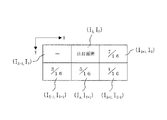
図2は、図1の重み係数記憶部7内の重み係数マトリクスの一例を示した図であり、X(処理方向)を水平方向とし、Yを垂直方向とし、注目画素(IX,IY)を含む6画素分が示されている。重み係数マトリクスは、これらの画素について、注目画素からの相対的位置と、重み係数とが対応づけられたデータテーブルである。
【0039】
処理方向が右方向であるとすれば、注目画素の左隣りの画素(IX−1,IY)は注目画素よりも先に量子化されているため、注目画素の誤差は配分されない。注目画素の誤差をErrとすれば、注目画素の右隣りの画素(IX+1,IY)、右斜め下の画素(IX+1,IY+1)、真下の画素(IX,IY+1)、左斜め下の画素(IX−1,IY+1)に配分される注目画素の誤差は、それぞれ次の様に求められる。
【0040】
【数1】

なお、図1の階調再現処理装置に使用される重み係数マトリクスは、この様な重み係数マトリクスには限定されない。重み係数マトリクスのサイズ及び重み係数は、必要に応じて任意に定めることができる。また、処理方向が左方向であれば、同じ重み係数マトリクスの左右を反転させて使用すればよい。さらに、処理方向により重み係数マトリクスを異ならせることもできる。つまり、処理方向が左方向の場合と右方向の場合で、重み係数やマトリクスサイズを異ならせてもよい。
【0042】
補正処理部8は、誤差配分量決定部6により決定された配分誤差データに基づいて未処理の画像データを補正し、注目画素の量子化誤差を拡散させるデータ補正手段である。補正対象となるのは、重み係数マトリクスのサイズに応じて決まる注目画素の周辺画素の画像データである。この補正処理は、画像データ記憶部1に保持されている画像データを配分誤差データを加えた値に更新することによって行われる。
【0043】
この様にして、画像データ記憶部1に格納された入力画像データPi(X,Y)は、周辺画素について量子化処理が行われるごとに補正処理され更新される。このため、量子化処理のために処理方向制御部2により読み出された時点では、必要な補正処理が行われた補正データPm(X,Y)に変換されている。
【0044】
図3のステップS101〜S106は、図1の階調再現処理装置10の概略動作の一例について示したフローチャートである。まず初めに、入力画像データPi(X,Y)が画像データ記憶部1に格納されているものとする。画像データ記憶部1内の画像データは、処理方向制御部2によって読み出される(ステップS101)。画像データの読み出しは、ラインごとに交互に異なる方向となるように行われているものとする。
【0045】
読み出された画像データは、量子化処理部3において量子化される(ステップS102)。この量子化処理は、処理方向により量子化ステップ数が異なり、階調数の異なる出力画像データPo(X,Y)が生成される。次に、誤差抽出部4において、量子化処理前後の画像データについて差分が求められ、量子化誤差として誤差バッファ5に格納される(ステップS103)。
【0046】
この量子化誤差は、誤差配分量決定部6により、未処理の周辺画素に配分され(ステップS104)、補正処理部8によって、画像データ記憶部1内の画像データに対して補正処理が行われる。この様な動作により、1画素の画像データについての量子化処理と、当該処理で生じた量子化誤差を周辺画素に拡散させる補正処理とが完了する。
【0047】
その後、処理方向制御部2が、画像データ記憶部1から次の画素の画像データを読み出して、1つのラインについて同じ動作が繰り返される。1つのライン上の全ての画素について処理が終了すれば、次のラインについて同様の処理が行われる。この様にしてステップS101〜S105の動作が、全ての画素について量子化処理が完了するまで繰り返される(ステップS106)。
【0048】
図4は、図1の処理方向制御部2における画像データの処理方向の一例を示した図であり、X(処理方向)を水平方向、Yを垂直方向とし、一部の画素とその処理方向が示されている。1ライン上の画像データが処理方向へ順次に読み出され、1ラインの読み出しが終了すれば、次のラインについて同様の読み出しが行われる。このとき、処理方向は1ラインごとに切り替えられ、奇数行目が右方向、偶数行目が左方向とされる。
【0049】
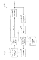
図5は、図1の量子化処理部3の一構成例を示したブロック図である。この量子化処理部3は、多値閾値処理部20、閾値制御部21及び閾値記憶部22により構成される。
【0050】
閾値記憶部22は、予め定められた複数の閾値を記憶保持する記憶手段であり、それぞれが複数の閾値からなる第1の閾値セット221及び第2の閾値セット222を記憶保持している。
【0051】
閾値制御部21は、処理方向制御部2からの処理方向データdiに基づいて閾値を選択し、選択された閾値を多値閾値処理部20へ出力する閾値選択手段である。ここでは、処理方向が右方向の場合に、第1の閾値セット221を選択し、処理方向が左方向の場合に、第1及び第2の閾値セット221,222を選択するものとする。
【0052】
多値閾値処理部20は、選択された複数の閾値に基づいて、処理方向制御部2からの補正画像データPm(X,Y)を量子化して量子化データを生成し、出力画像データPo(X,Y)として出力している。この量子化処理は、処理方向によって異なる。
【0053】
処理方向が右方向の場合、第1の閾値セット221に基づいて量子化データが求められ、この量子化データが出力画像データPo(X,Y)となる。また、処理方向が左方向の場合には、第1の閾値セット221に基づいて第1の量子化データが求められるとともに、第2の閾値セット222に基づいて第2の量子化データが求められ、第1及び第2の量子化データの平均値が出力画像データPo(X,Y)となる。
【0054】
図6のステップS201〜S206は、図5の量子化処理部3の動作の一例を示したフローチャートであり、図3における量子化処理(ステップS102)の詳細が示されている。画像データPm(X,Y)が入力されると、閾値制御部21が、閾値記憶部22から第1の閾値セット221を読み出し、多値閾値処理部20へ出力する(ステップS201)。多値閾値処理部20は、画像データPm(X,Y)をこの閾値セット221の各閾値と比較し、量子化データを生成する(ステップS202)。処理方向が右方向である場合には、ステップS202で得られた量子化データが出力画像データPo(X,Y)として出力され、1画素の量子化処理が完了する(ステップS203)。処理方向は、処理方向データdiに基づき判断される。
【0055】
一方、処理方向が左方向の場合には、閾値制御部21が、さらに閾値記憶部22から第2の閾値セット222を読み出し、多値閾値処理部20へ出力する(ステップS204)。多値閾値処理部20は、画像データPm(X,Y)をこの閾値セット222の各閾値と比較し、量子化データを生成する(ステップS205)。その後、多値閾値処理部20は、ステップS202及びS205で得られた量子化データの平均値を求め(ステップS206)、出力画像データPo(X,Y)として出力し、処理方向が左方向の場合における1画素の量子化処理が完了する。
【0056】
図7は、図5の第1の閾値セット221を用いた多値閾値処理の一例を示した図であり、256階調の入力値と、5階調の量子化値との対応関係が示されている。ここでは、5値出力の場合について説明するが、量子化処理の階調ステップ数は必要に応じて任意に設定することができる。なお、入力値は、補正画像データPm(X,Y)の各階調に対応し、量子化値は、出力画像データPo(X,Y)の各階調に対応している。
【0057】
閾値Lth1〜Lth4は、第1の閾値セット221を構成する閾値である。5つの量子化ステップは、それぞれが8ビットの量子化値により表わされ、0,64,128,192,255であるものとする。このとき、閾値Lth1〜Lth4は、次式を満たすように予め定められる。
【0058】
【数2】
処理方向が右方向の場合、補正画像データPm(X,Y)が、各閾値Lth1〜Lth4と順次に比較され、この比較結果に基づいて量子化され、出力画像データPo(X,Y)となる。例えば、補正画像データPm(X,Y)と閾値Lth1との大小が比較され、補正画像データPm(X,Y)が閾値Lth1よりも小さい場合には0を量子化データとする。閾値Lth1よりも大きい場合には、閾値Lth2と比較され、閾値Lth2よりも小さい場合には64を量子化データとする。閾値Lth2よりも大きい場合には、さらに閾値Lth3と比較される。同様の処理が閾値Lth4まで行われて量子化レベルが決定され、その量子化データが補正画像データPo(X,Y)とされる。
【0060】
なお、これらの閾値Lth1〜Lth4と量子化値は、出力装置に依存する値であるため、例えば、インクジェット方式の出力装置の場合、あるドットパターンをそれぞれの量子化値に対応したインクドロップにて出力し、それぞれの単位面積当たりの濃度を測定し、その結果に基づいて予め最適化しておく必要がある。
【0061】
図8は、図5の第2の閾値セット222を用いた多値閾値処理の一例を示した図であり、比較のために第1の閾値セット221とともに示されている。図7の第1の閾値セット221の場合と同様、256階調の入力値と、5階調の量子化値との対応関係が示されている。
【0062】
閾値Rth1〜Rth4は、第2の閾値セット222を構成する閾値である。量子化ステップ数及び量子化値は、第1の閾値セット221の場合と同じ値であるが、その閾値Rth1〜Rth4は、閾値Lth1〜Lth4よりも大きな値、例えば数階調分だけ変化させた値となっている。つまり、閾値Rth1〜Rth4は、次式を満たすように予め定められる。
【0063】
【数3】
処理方向が左方向の場合、まず、補正画像データPm(X,Y)が、各閾値Lth1〜Lth4と順次に比較され、この比較結果に基づいて量子化され、第1の量子化データが生成される。次に、各閾値Rth1〜Rth4と順次に比較され、この比較結果に基づいて量子化され、第2の量子化データが生成される。そして、第1及び第2の量子化データの平均値が求められ、出力画像データPo(X,Y)とされる。
【0065】
第1及び第2の量子化データが同一であれば、これらの値がそのまま平均値となり、出力画像データPo(X,Y)となる。従って、処理方向が右方向の場合と同じ量子化処理となり、同じ結果が得られる。これに対し、第1及び第2の量子化データが異なる場合には、右方向の量子化処理における5つの量子化値以外の新たな量子化値が擬似的に生成される。
【0066】
つまり、処理方向が左方向の場合には、右方向の場合に比べ、量子化処理における量子化ステップ数を増大させ、出力画像データPo(X,Y)の階調数を増大させることができる。しかも、これらの新たな量子化値は、処理方向が右方向の場合における各量子化値の間の値(隣接する2つの量子化値の平均値)として定められるため、バランスを保ちながら擬似的に階調レベルを増やすことができる。
【0067】
なお、第1の閾値セット221に対する第2の閾値セット222の閾値変化量は、それぞれの出力装置とインク特性に応じて、最適化されることが望ましい。第1及び第2の閾値セット221,222を構成する各閾値の差分が、多値誤差拡散処理された出力画像のドットパターンに影響を及ぼすため、高濃度インクと低濃度インクを用いて、それぞれの色における、あるドットパターンを出力し、両者の濃度値の違いから、最適となるような第2の閾値セットを算出しておくことが望ましい。
【0068】
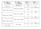
例えば、第1の閾値セット221をLth1=32,Lth2=96,Lth3=160,Lth4=223とし、第2の閾値セット222をRth1=37,Rth2=101,Rth3=165,Rth4=228とした場合、注目画素の補正画像データがPm=97であれば、2種類の閾値セット221,222を用いて、以下のように出力画像データPoが決定される。
【0069】
まず、第1の閾値セット221と比較される。Lth2<Pmであるから、第1の量子化値は128となる。次に、第2の閾値セット222と比較され、Pm<Rth2であるから、第2の量子化データは64となる。これら2つの値の平均値を取ることによって、新たな量子化値である量子化データ96が生成される。
【0070】
また、注目画素の補正画像データがPm=90であれば、2種類の閾値セット221,222を用いて、以下のように出力画像データPoが決定される。まず、第1の閾値セット221と比較され、Pm<Lth1であるから、第1の量子化値は64となる。次に、第2の閾値セット222と比較され、Pm<Rth2であるから、第2の量子化データも64となる。これら2つの値の平均値を取ることによって、量子化データ64が生成される。
【0071】
この様にして、2種類の閾値セット221,222の閾値の数を同一とし、対応する各閾値を異ならせることによって、補正画像データが対応する閾値の間の値である場合には、量子化データの平均値は、新たな量子化値となる。すなわち、平均演算により新たな量子化値を生成することができる。なお、2種類の閾値セット221,222の対応する各閾値の差は、少なくとも量子化ステップ幅よりも小さい値とする必要があり、僅かにずらした値とすることが望ましい。
【0072】
出力画像データPo(X,Y)に基づいて画像を形成する出力装置が、同一色であって濃度の異なる2種類のインク(濃淡インク)を有する場合、平均値演算によって生成された新たな階調レベルを低濃度インクに割り当て、その他の階調レベルを高濃度インクに割り当てることができる。この場合、出力装置のインク制御部、例えばインクジェットプリンタであればインジェットヘッドに対し、出力画像データPo(X,Y)とともに、高濃度インク又は低濃度インクを指定する制御信号も出力される。この制御信号は、処理方向データdiと、処理方向が左方向の場合における2つの量子化データの比較結果に基づいて求めることができる。
【0073】
この様にして出力画像データを高濃度インク及び低濃度インクに割り当てることにより、インク分割カーブを用いることなく2種類のインクを使用することができる。また、広範囲の濃度にわたり、低濃度インクを使用して画像形成を行うことが可能となり、濃度切り替え部位におけるトーンジャンプを解消することができる。
【0074】
図9は、処理方向が右方向の場合における量子化処理と、割り当てられる濃淡インクとの関係を示した図である。右方向の処理時には、全ての出力画像データPo(X,Y)が高濃度インクの制御に使用される。すなわち、高濃度インクのドロップサイズやドロップ数が出力画像データPo(X,Y)により制御され、常に高濃度インクが吐出される。
【0075】
図10は、処理方向が左方向の場合における量子化処理と、割り当てられる濃淡インクとの関係を示した図である。左方向の処理時には、出力画像データPo(X,Y)に応じて、濃淡インクのいずれか一方が割り当てられる。すなわち、第1及び第2の量子化データが一致する場合には、左方向の処理時と同様、出力画像データPo(X,Y)が高濃度インクの制御に使用され、当該量子化値に基づいて高濃度インクが吐出される。また、第1及び第2の量子化データが異なる場合には、出力画像データPo(X,Y)が低濃度インクの制御に使用され、平均値に基づいて低濃度インクが吐出される。
【0076】
第1及び第2の閾値セット221,222の各閾値と量子化値は、出力装置に依存するため、出力装置を使って、あるドットパターンをそれぞれの量子化値に対応したインクドロップにて出力し、それぞれの単位面積当たりの濃度を測定し、その結果に基づいて予め最適化しておく必要がある。
【0077】
このとき、第1の閾値セット221については、高濃度インクを用いて出力し、最適な閾値Lth1〜Lth4を予め算出しておく必要がある。また、第2の閾値セット222については、高濃度インク及び低濃度インクを用いてそれぞれ出力し、両者の濃度差から最適となる閾値Rth1〜Rth4を算出しておく必要がある。
【0078】
本実施の形態によれば、2次元画像について誤差拡散処理を行う際、ラインにより処理方向を異ならせるとともに、処理方向ごとに量子化処理を異ならせ、ラインにより量子化データの階調ステップ数を増大させている。このため、階調再現性に優れた誤差拡散処理を行うことができる。特に、閾値の異なる第1及び第2の閾値セットによりそれぞれ量子化処理を行って、2つの量子化データの平均値を求めているため、バランスを保ちながら量子化ステップ数を疑似的に増加させることができる。
【0079】
また、処理方向により量子化ステップ数を異ならせ、量子化ステップの増大分(新たに生成された階調レベル)を濃淡インクの一方に割り当てるとともに、他の量子化ステップ(その他の階調レベル)を他方に割り当てている。このため、インク分割カーブを使用することなく、濃淡インクへの割り当てを行うことができ、低コストで階調再現性に優れた誤差拡散処理を行うことができる。特に、中間濃度領域におけるテクスチャの改善を図ることができる。
【0080】
また、処理方向により量子化処理を異ならせるとともに、重み係数マトリクスを異ならせることによって、更に階調再現性に優れた誤差拡散処理を行うことができる。
【0081】
なお、本実施の形態では、量子化ステップ数を変化させて、その増大分を低濃度インクに割り当てる場合について説明したが、本発明は、この様な場合に限定されない。例えば、濃淡インクへの割り当て行わない場合であっても、ラインにより処理方向を異ならせ、擬似的に階調数を増大させ、誤差拡散処理における階調再現性を向上させることができる。従って、インクジェットプリンタ以外の出力装置にも本発明を適用することができる。また、濃淡インクへの割り当てを行う場合であっても、その割り当ては任意に行うことができ、本実施の形態の例に限定されない。
【0082】
実施の形態2.
本実施の形態では、実施の形態1の階調再現処理装置10において、画像データにブルーノイズを加えて量子化処理することによって、ハイライト領域及び中間濃度領域における再現性を向上させる場合について説明する。
【0083】
図11は、本発明の実施の形態2による階調再現処理装置11の一構成例を示したブロック図である。この階調再現処理装置11は、図1の階調再現処理装置10(実施の形態1)と比較すれば、量子化処理部3の構成が異なる。
【0084】
入力画像データPi(X,Y)として、シアンC、マゼンタM、イエローY、ブラックKの各色成分Ceごとの画像データPi(X,Y,Ce)が与えられる場合、画像データ記憶部1に保持された各色成分Ceごとの画像データが、処理方向制御部2により順次に読み出され、量子化処理部3において順次に量子化される。このとき、処理方向制御部2から量子化処理部3に対し、読み出した画像データPm(X,Y,Ce)の属性情報として、画素位置データX,Y及び色成分データCeが出力される。
【0085】
図12は、図11の量子化処理部3の一構成例を示したブロック図である。この量子化処理部3は、図5の量子化処理部3(実施の形態1)に比べれば、ノイズ付加処理部24及びノイズデータ記憶部25が設けられている点で異なる。
【0086】
ノイズデータ記憶部25は、ノイズデータを記憶する記憶手段である。ノイズ付加処理部24は、処理方向制御部2からの補正画像データPm(X,Y,Ce)に対し、ノイズデータ記憶部25から読み出したノイズデータを付加し、多値閾値処理部20へ出力している。
【0087】
ノイズデータ記憶部25は、各色成分ごとに異なるブルーノイズのデータテーブルを予め記憶保持している。図中の25Cはシアン用、25Mはマゼンタ用、25Yはイエロー用、25Kはブラック用のブルーノイズテーブルである。ノイズ付加処理部24は、処理方向制御部2からの色成分データCeに基づいて、ブルーノイズテーブル25C〜25Kのいずれかを選択し、補正画像データPm(X,Y,Ce)に加えている。
【0088】
ブルーノイズとは、人間の目では知覚し難い空間周波数を有するパターンデータである。人間の視覚は、ある空間周波数以上ではほとんど感度がなく、視覚系のMTF(Modulation Transfer Function)は、一種の低域フィルタであることが知られている(例えば非特許文献2のp47参照)。この性質を利用して、擬似的なランダムパターンを操作し、その空間周波数の主要成分が視覚系MTFのカットオフ周波数以上の帯域に分布するパターンを生成すれば、ブルーノイズが得られる。
【0089】
この様なブルーノイズを画像データに加えることによって、ドット密度の疎となるハイライト領域におけるドットの分散性を向上させることができる。また、中間濃度部におけるテクスチャーを改善することができる。
【0090】
図13は、2値出力の場合に使用されるブルーノイズの一例を示した図である。ブルーノイズは、通常、256×256画素に関するデータマトリクスとして与えられ、このようなデータテーブルはブルーノイズマスクと呼ばれている。256階調の画像データを2値化する場合であれば、ブルーノイズマスクを構成する各データは、その絶対値の大きさが127以下の値とされる。
【0091】
図14は、図12のブルーノイズテーブル25C,25M,25Y,25Kの一例を示した図である。多値データへの量子化処理を行う場合であれば、量子化ステップ幅に合わせて、ブルーノイズテーブルを最適化して使用することが望ましい。図14に示されたブルーノイズテーブルは、量子化ステップ幅に基づいて正規化された5値出力用のデータテーブルである。
【0092】
すなわち、実施の形態1の場合と同様、5値出力の場合であって、第1の閾値セットの各閾値をLth1=32,Lth1=96,Lth1=160,Lth1=223とし、量子化値を0,54,128,192,255とすれば、ノイズデータの大きさは64(量子化値)−32(Lth1)=32の範囲内に正規化しておくことが望ましい。
【0093】
図15のステップS301〜S307は、図12の量子化処理部3の動作の一例を示したフローチャートであり、図3における量子化処理(ステップS102)の詳細が示されている。画像データが入力されると、まず最初に、ステップS301において、ノイズ付加処理部24によりブルーノイズが付加される。このとき、色成分データCeに基づいて、ノイズテーブル25C〜25Kのいずれかが選択され、画素位置データX,Yに基づいて、ノイズテーブル中のいずれかのノイズデータが選択され、画像データに付加される。その後のステップS302〜S307は、多値閾値処理部20及び閾値制御部21における動作であり、図6ステップのS201〜S206と全く同様である。
【0094】
本実施の形態によれば、人間の視覚特性に知覚しがたいブルーノイズを画像データに加えて多値誤差拡散を行っているため、ハイライト領域におけるドットの分散性や、中間濃度領域におけるテクスチャの改善を図ることができる。
【0095】
なお、本実施の形態では、処理方向制御部2からの色成分データCeに基づいて、ブルーノイズテーブル25C〜25Kのいずれかを選択し、補正画像データPm(X,Y,Ce)に加える場合の例について説明した。この場合、シアンC、マゼンタM、イエローY、ブラックKの各色成分ごとの画像データPi(X,Y,Ce)は、同一の階調再現処理装置12においてシリアルに処理されるが、本発明は、この様な場合に限定されるものではない。例えば、図11に示された階調再現処理装置11を色成分ごとに設け、各色成分ごとの画像データPi(X,Y,Ce)を並列に処理することもできる。
【0096】
実施の形態3.
上記実施の形態1,2では、第1及び第2の閾値セット221,222を用いて量子化処理を行う階調再現処理装置の例について説明したが、本実施の形態では、ルックアップテーブル(LUT:Look−Up Table)を用いて量子化処理を行う階調再現処理装置の場合について説明する。
【0097】
図16は、本発明の実施の形態3による階調再現処理装置の要部の一構成例を示したブロック図であり、図1における量子化処理部3の他の構成例が示されている。この量子化処理部3は、多値閾値処理部20及びLUT記憶部23により構成される。
【0098】
LUT記憶部23は、予め定められた複数のルックアップテーブルを記憶保持する記憶手段であり、第1のLUT231及び第2のLUT232を記憶している。第1及び第2のLUT231,232は、それぞれが補正画像データPm(X,Y)を量子化値に対応づけたデータテーブルである。
【0099】
多値閾値処理部20は、処理方向制御部2からの処理方向データdiに基づき、第1及び第2のLUT231,232を参照して、補正画像データPm(X,Y)を量子化し、出力画像データPo(X,Y)を生成している。このときの量子化ステップ数は、実施の形態1と同様、処理方向により異なる。
【0100】
図17は、第1のLUT231の入出力関係の一例を示した図である。第1のLUT231は、補正画像データPm(X,Y)が入力されると、実施の形態1において第1の閾値セット221により量子化された量子化データ(第1の量子化データ)と同じデータを出力する。すなわち、補正画像データPm(X,Y)が入力された場合に、Pm<32であれば0、32≦Pm<96であれば64、96≦Pm<160であれば128、160≦Pm<223であれば192、223≦Pmであれば255が出力される。
【0101】
図18は、第2のLUT232の入出力関係の一例を示した図である。第2のLUT232は、補正画像データPm(X,Y)が入力されると、実施の形態1において第2の閾値セット222により量子化された量子化データ(第2の量子化データ)と同じデータを出力する。すなわち、補正画像データPm(X,Y)が入力された場合に、Pm<37であれば0、37≦Pm<101であれば64、101≦Pm<165であれば128、165≦Pm<228であれば192、228≦Pmであれば255が出力される。
【0102】
図19のステップS401〜S404は、図16の量子化処理部3の動作の一例を示したフローチャートであり、図3における量子化処理(ステップS102)の詳細が示されている。画像データPm(X,Y)が入力されると、多値閾値処理部20が、LUT記憶部23内の第1のLUT231を参照し、画像データPm(X,Y)から量子化データを求める(ステップS401)。処理方向が右方向である場合には、この量子化データが出力画像データPo(X,Y)として出力され、1画素の量子化処理が完了する(ステップS402)。処理方向は、処理方向データdiに基づき判断される。
【0103】
一方、処理方向が左方向の場合には、多値閾値処理部20が、さらにLUT記憶部23内の第2のLUT232を参照し、画像データPm(X,Y)から量子化データを求める(ステップS403)。その後、多値閾値処理部20は、ステップS401及びS403で得られた量子化データの平均値を求め(ステップS404)、出力画像データPo(X,Y)として出力し、処理方向が左方向の場合における1画素の量子化処理が完了する。
【0104】
本実施の形態によれば、第1及び第2のLUTを用いて、第1及び第2の量子化データを求めている。このため、画像データを複数の閾値と比較して行われる多値閾値による判断処理を省略することができ、高速処理が可能となる。
【0105】
なお、本実施の形態では、実施の形態1の量子化処理部3においてLUTを用いた量子化処理を行う場合の例について説明したが、全く同様にして、ブルーノイズを付加する実施の形態2の量子化処理部3においてLUTを用いた量子化処理を行うこともできる。
【0106】
実施の形態4.
実施の形態1〜3では、ラインにより処理方向を異ならせるとともに、量子化処理を異ならせる階調再現処理装置の例について説明した。本実施の形態では、処理方向を一定方向とし、ラインにより量子化処理を異ならせる階調再現処理装置の場合について説明する。
【0107】
図20は、本発明の実施の形態4による階調再現処理装置12の一構成例を示したブロック図である。この階調再現処理装置12は、図1の階調再現処理装置10(実施の形態1)と比較すれば、処理方向制御部2及び量子化処理部3の動作が異なる。
【0108】
処理方向制御部2は、全てのラインについて同一方向に走査する、いわゆるラスタースキャン処理を行っている。図21は、この様子を示した図である。同一ライン上の補正画像データPm(X,Y)は、常に一定方向に走査しながら読み出され、各ラインに対し、処理方向を変化させることなく順次に読み出しが行われる。また、処理方向制御部2からは、ラインデータYが量子化処理部3に対して出力される。
【0109】
量子化処理部3は、このラインデータYに基づいて、補正画像データPm(X,Y)の量子化処理を行っている。量子化処理部3における処理は、ラインにより量子化ステップ数が異なり、階調数の異なる出力画像データPo(X,Y)が生成される。
【0110】
この量子化処理部3は、ラインごとに量子化処理を任意に制御することができる。例えば、ラインごとに量子化処理を切り替え、あるいは、2以上のラインごとに切り替えることができる。ここでは、ラインごとに2種類の量子化処理を切り替えるものとする。
【0111】
図22は、図20の量子化処理部3の一構成例を示したブロック図である。この量子化処理部3は、多値閾値処理部20、閾値制御部21及び閾値記憶部22により構成される。図5の量子化処理部3(実施の形態1)と比べれば、閾値制御部21の動作が異なる。
【0112】
閾値制御部21は、処理方向制御部2からのラインデータYに基づいて、閾値記憶部22に記憶された閾値を選択し、選択された閾値を多値閾値処理部20へ出力する閾値選択手段である。ここでは、偶数行目のラインの場合に、第1の閾値セット221を選択し、奇数行目のラインの場合に、第1及び第2の閾値セット221,222を選択するものとする。
【0113】
多値閾値処理部20は、選択された複数の閾値に基づいて、処理方向制御部2からの補正画像データPm(X,Y)を量子化して量子化データを生成し、出力画像データPo(X,Y)として出力している。この量子化処理は、ラインにより異なる。
【0114】
図23のステップS501〜S506は、図22の量子化処理部3の動作の一例を示したフローチャートであり、図3における量子化処理(ステップS102)の詳細が示されている。画像データPm(X,Y)が入力されると、閾値制御部21が、閾値記憶部22から第1の閾値セット221を読み出し、多値閾値処理部20へ出力する(ステップS501)。多値閾値処理部20は、画像データPm(X,Y)をこの閾値セット221の各閾値と比較し、量子化データを生成する(ステップS502)。偶数行目のラインである場合には、ステップS502で得られた量子化データが出力画像データPo(X,Y)として出力され、1画素の量子化処理が完了する(ステップS503)。偶数行目のラインであるか否かは、ラインデータYに基づき判断される。
【0115】
一方、奇数行目のラインの場合には、閾値制御部21が、さらに閾値記憶部22から第2の閾値セット222を読み出し、多値閾値処理部20へ出力する(ステップS504)。多値閾値処理部20は、画像データPm(X,Y)をこの閾値セット222の各閾値と比較し、量子化データを生成する(ステップS505)。その後、多値閾値処理部20は、ステップS502及びS505で得られた量子化データの平均値を求め(ステップS506)、出力画像データPo(X,Y)として出力し、奇数行目における1画素の量子化処理が完了する。
【0116】
本実施の形態によれば、2次元画像について誤差拡散処理を行う際、ラインにより量子化処理を異ならせ、量子化データの階調ステップ数を擬似的に増大させている。このため、階調再現性に優れた誤差拡散処理を行うことができる。特に、閾値の異なる第1及び第2の閾値セットによりそれぞれ量子化処理を行って、2つの量子化データの平均値を求めているため、バランスを保ちながら量子化ステップ数を疑似的に増加させることができる。
【0117】
なお、本実施の形態では、実施の形態1の量子化処理部3において処理方向を一定とし、ラインにより量子化処理を異ならせる場合について説明したが、全く同様にして、実施の形態2及び実施の形態3の量子化処理部3において処理方向を一定とし、ラインにより量子化処理を異ならせることもできる。
【0118】
実施の形態5.
上記実施の形態1〜4では、階調再現処理装置10〜12の例について説明したが、本実施の形態では、この様な階調再現処理装置10〜12を備えた画像形成装置の例について説明する。
【0119】
図24は、本発明の実施の形態5による画像形成装置70の一構成例を示したブロック図であり、デジタルカラー複写機の例が示されている。この画像形成装置70は、カラー画像入力装置30、カラー画像処理装置31、カラー画像出力装置32及び操作パネル33により構成される。
【0120】
カラー画像入力装置30は、例えばCCD(Charge Coupled Device)を備えたスキャナ部より構成される画像読取手段であり、原稿からの反射光像はCCDにより読み取られ、RGB(R:赤、G:緑、B:青)のアナログ信号が生成される。このRGB信号は、カラー画像処理装置31へ出力される。
【0121】
カラー画像処理装置31では、カラー画像入力装置30からのRGB信号に対し、補正処理、階調処理などの種々のデータ処理が行われ、CMYK(C:シアン、M:マゼンタ、Y:イエロー、K:ブラック)のデジタルカラー信号が生成される。このCMYK信号は、一旦、図示しない記憶手段に記憶され、所定のタイミングで読み出され、カラー画像出力装置32に出力される。
【0122】
カラー画像出力装置32は、CMYK信号に基づいて、カット紙などの記録媒体上に画像を形成する出力装置である。本実施の形態による画像形成装置70の場合、例えば、電子写真方式あるいはインクジェット方式を用いたカラー画像出力装置として実現される。
【0123】
操作パネル33は、オペレータがキー操作などにより指示入力を行うための入力手段である。オペレータの指示は、制御信号として、操作パネル33からカラー画像入力装置30、カラー画像処理装置31及びカラー画像出力装置32へ出力される。
【0124】
この様にして、オペレータの指示により、カラー画像入力装置30で原稿画像が読み取られ、カラー画像処理装置31によるデータ処理後に、カラー画像出力装置32によって記録媒体上に画像が形成され、デジタルカラー複写機として機能する。
【0125】
カラー画像処理装置31は、さらに、A/D変換部311、シェーディング補正部312、入力階調補正部313、領域分離処理部314、色補正部315、黒生成下色除去部316、空間フィルタ処理部317、出力階調補正部318及び階調再現処理部319により構成される。階調再現処理部319は、上記実施の形態1〜4の階調再現処理装置10〜12に相当し、更に付加的な機能を備えている。
【0126】
A/D(アナログ/デジタル)変換部311は、RGBのアナログ信号をデジタル信号に変換するデジタル変換部である。シェーディング補正部312は、A/D変換部311より送られてきたデジタルのRGB信号に対して、カラー画像入力装置の照明系、結像系、撮像系で生じる各種の歪みを取り除く処理を行う処理部である。
【0127】
入力階調補正部313は、シェーディング補正部312において各種の歪みが取り除かれたRGB信号(RGBの反射率信号)に対して、カラーバランスを整えると同時に、濃度信号などカラー画像処理装置に採用されている画像処理システムの扱い易い信号に変換する処理を行う処理部である。
【0128】
領域分離処理部314は、入力画像中の各画素を文字領域、網点領域、写真領域の何れかに分離する処理部である。この領域分離処理部314は、分離結果に基づいて、画素がどの領域に属しているかを示す領域識別信号を黒生成下色除去部316、空間フィルタ処理部317及び階調再現処理部319へ出力する。また、入力階調補正部313から出力された入力信号をそのまま後段の色補正部315に出力する。
【0129】
色補正部315は、色再現を忠実に行うため、不要吸収成分を含むCMY(C:シアン・M:マゼンタ・Y:イエロー)色材の分光特性に基づいた色濁りを取り除く処理を行う処理部である。
【0130】
黒生成下色除去部316は、色補正後のCMYの3色信号から黒(K)信号を生成する黒生成、元のCMY信号から黒生成で得たK信号を差し引いて新たなCMY信号を生成する処理部であり、CMYの3色信号はCMYKの4色信号に変換される。
【0131】
一般的な黒生成処理として、スケルトンブラックにより黒生成を行う方法がある。この方法では、スケルトンカーブの入出力特性をy=f(x)、入力されるデータをC,M,Y、出力されるデータをC’,M’,Y’,K’、UCR(Under Color Removal)率をα(0<α<1)とすると、黒生成下色除去処理は、次式で表わされる。
【0132】
【数4】
空間フィルタ処理部317は、黒生成下色除去部316より入力されるCMYK信号の画像データに対して、領域識別信号に基づいてデジタルフィルタによる空間フィルタ処理を行い、空間周波数特性を補正することによって出力画像のぼやけや粒状性劣化を防ぐ処理を行っている。階調再現処理部319も、空間フィルタ処理部317と同様に、CMYK信号の画像データに対して、領域識別信号に基づいて所定の処理を施すものである。
【0134】
例えば、領域分離処理部314によって文字として分離された領域は、特に黒文字或いは色文字の再現性を高めるために、空間フィルタ処理部317での空間フィルタ処理における鮮鋭強調処理により高周波数の強調量が大きくされる。同時に、階調再現処理部319においては、高域周波数の再現に適した高解像度のスクリーンでの二値化または多値化処理が選択される。
【0135】
また、領域分離処理部314により網点として分離された領域に関しては、空間フィルタ処理部317において、入力網点成分を除去するためのローパス・フィルタ処理が施される。そして、出力階調補正部318では、濃度信号などの信号をカラー画像出力装置の特性値である網点面積率に変換する出力階調補正処理が行われた後、階調再現処理部319において、最終的に画像を画素に分離してそれぞれの階調を再現できるように処理する階調再現処理(中間調生成)が施される。
【0136】
領域分離処理部314により写真に分離された領域に関しては、階調再現処理部319において、階調再現性を重視したスクリーンでの二値化または多値化処理が行われる。
【0137】
実施の形態6.
実施の形態5では、本発明の適用例として、デジタルカラー複写機の場合について説明した。本実施の形態では、他の適用例として、画像形成装置がコンピュータ及びプリンタにより構成される場合について説明する。
【0138】
図25は、本発明の実施の形態6による画像形成装置71の一構成例を示したブロック図である。この画像形成装置71は、コンピュータ40及びプリンタ41により構成される。
【0139】
画像データは、例えばスキャナやデジタルカメラからコンピュータ40へ入力される。コンピュータ40に入力された画像データは、図示しない各種のアプリケーションプログラムにより画像の加工・編集等が行われる。このようにして処理された画像データは、プリンタ・ドライバ42に入力される。
【0140】
プリンタ・ドライバ42は、コンピュータ40上で実行されるコンピュータプログラムであり、色補正部45、階調再現処理部46及びプリンタ言語翻訳部47により構成される。色補正部45では補正処理が行われ、階調再現処理部46では多値誤差拡散処理が行われる。このとき、色補正部45では、黒生成下色除去処理も行われる。また、階調再現処理部46は、上記実施の形態1〜4の階調再現処理装置10〜12に相当する。
【0141】
上記処理がなされたデータは、プリンタ言語翻訳部47でプリンタ言語に変換され、通信ポートドライバ43、通信ポート44(RS232C、LAN等)を介して電子写真方式やインクジェット方式のプリンタ41(画像出力装置)へ出力される。プリンタ41は、プリンタ機能に加えて、コピー機能、ファクシミリ機能を有するデジタル複合機であってもよい。
【0142】
なお、本発明による誤差拡散処理装置がコンピュータにより実現される場合、当該コンピュータにより実行される処理手順はコンピュータプログラムとして提供することができる。そして、当該コンピュータプログラムは、それを記録したコンピュータ読み取り可能な記録媒体として提供され、あるいは、電気通信回線を介してダウンロードすることにより提供される。
【0143】
この記録媒体は、固定的にプログラムを担持可能であって、コンピュータによって直接的又は間接的に読み取り可能な記憶媒体であればよい。例えば、ROM、RAM等などの半導体素子でも良いし、フレキシブルディスク、ハードディスク、MD、磁気テープなどの磁気記憶媒体でも良いし、CD−ROM、MO、DVDなどの光記憶媒体でも良く、その記録方式及び読取方式は問わない。
【0144】
実施の形態7.
図26は、本発明の実施の形態7による画像形成装置の一部を示した図であり、インクジェット記録装置72の一構成例が示された透視斜視図である。このインクジェット記録装置72は、複写機、プリンタ、デジタル複合機などの出力装置として用いられるインク記録手段である。
【0145】
このインクジェット記録装置は、印字ヘッド(インクジェットヘッド)50、キャリッジ51、搬送ローラ52、ガイドシャフト53、保持手段54、モータ55、駆動ベルト56及びメンテナンスユニット57により構成される。
【0146】
キャリッジ51は、印字ヘッド50を搭載し、カット紙などの記録媒体58に対して、矢符X1およびX2方向の主走査方向に相対的に移動可能である。そして、記録媒体58は図示しない給紙部から矢符Yの副走査方向に給送されながら、矢符X1およびX2方向に移動する印字ヘッド50により画像形成が行われる。給紙部に備えられている記録媒体58は、図示しない給紙ローラにより1枚ずつ送り出され、記録媒体搬送手段である搬送ローラ52により印字ヘッド50部分に供給される。記録が終了した記録媒体58は、図示しない排紙部に排出される。
【0147】
上記印字ヘッド50は、上記主走査方向に延びるガイドシャフト53及び保持手段54上に摺動自在に支持されて、記録媒体58に対する位置が決められる。さらに、駆動手段であるモータ55によって駆動される駆動ベルト56が上記ガイドシャフト53と平行に張架されており、上記印字ヘッド50は駆動ベルト56によって変位駆動される。なお、メンテナンスユニット57は、印字ヘッド50のクリーニングなどのメンテナンスが実施される部分である。
【0148】
図27は、図26の印字ヘッド50の詳細構成例を示した斜視図である。印字ヘッド50は、複数色のインクタンク500と、各インクタンクに対応して設けられたノズル501により構成される。ここでは、印字ヘッド50にシアンC、マゼンタM、イエローY、黒K、ライトシアンLC、ライトマゼンタLMよりなる6色のインクのインクタンクが備えられている。
【0149】
シアンC及びライトシアンLCは、同一色の濃淡インクであり、前者が高濃度インク、後者が低濃度インクである。同様にして、マゼンタM及びライトマゼンタLMも、同一色の濃淡インクであり、前者が高濃度インク、後者が低濃度インクである。これらのインクは、画像データに応じてノズル501より記録媒体上に吐出される。
【0150】
【発明の効果】
本発明によれば、画像データの誤差拡散処理を行う際、ラインにより量子化処理を異ならせ、一部のラインについて量子化ステップ数を増大させている。このため、階調再現性に優れた誤差拡散処理を行うことができる。また、本発明によれば、ラインにより処理方向及び量子化ステップ数を異ならせている。このため、階調再現性に優れた誤差拡散処理を行うことができる。
【0151】
また、本発明によれば、量子化ステップを増大させる際、閾値の異なる第1及び第2の閾値セットに基づいてそれぞれ量子化処理を行い、得られた2つの量子化データについて平均値を求めている。このため、バランスを保ちながら量子化ステップ数を疑似的に増加させることができる。
【0152】
また、本発明によれば、量子化ステップを増大させる際、第1及び第2のルックアップテーブルに基づいてそれぞれ量子化処理を行い、得られた2つの量子化データについて平均値を求めている。このため、バランスを保ちながら量子化ステップ数を疑似的に増加させる処理の高速化が可能となる。
【0153】
また、本発明によれば、ラインにより量子化ステップ数を増大させ、量子化ステップの一部を濃淡インクの一方に割り当てるとともに、他の量子化ステップを他方に割り当てている。このため、インク分割カーブを使用することなく、濃淡インクへの割り当てを行うことができ、低コストで階調再現性に優れた誤差拡散処理装置及び画像形成装置を提供することができる。
【図面の簡単な説明】
【図1】本発明の実施の形態1による階調再現処理装置10の一構成例を示したブロック図である。
【図2】図1の重み係数記憶部7内の重み係数マトリクスの一例を示した図である。
【図3】図1の階調再現処理装置10の概略動作の一例について示したフローチャートである。
【図4】図1の処理方向制御部2における画像データの走査順序の一例を示した図である。
【図5】図1の量子化処理部3の一構成例を示したブロック図である。
【図6】図5の量子化処理部3の動作の一例を示したフローチャートである。
【図7】図5の第1の閾値セット221を用いた多値閾値処理の一例を示した図である。
【図8】図5の第2の閾値セット222を用いた多値閾値処理の一例を示した図である。
【図9】処理方向が右方向の場合における量子化処理と、割り当てられる濃淡インクとの関係を示した図である。
【図10】処理方向が左方向の場合における量子化処理と、割り当てられる濃淡インクとの関係を示した図である。
【図11】本発明の実施の形態2による階調再現処理装置11の一構成例を示したブロック図である。
【図12】図11の量子化処理部3の一構成例を示したブロック図である。
【図13】2値出力の場合に使用されるブルーノイズの一例を示した図である。
【図14】図12のブルーノイズテーブル25C,25M,25Y,25Kの一例を示した図である。
【図15】図12の量子化処理部3の動作の一例を示したフローチャートである。
【図16】本発明の実施の形態3による階調再現処理装置の要部の一構成例を示したブロック図である。
【図17】第1のLUT231の入出力関係の一例を示した図である。
【図18】第2のLUT232の入出力関係の一例を示した図である。
【図19】図16の量子化処理部3の動作の一例を示したフローチャートである。
【図20】本発明の実施の形態4による階調再現処理装置12の一構成例を示したブロック図である。
【図21】図20の処理方向制御部2における画像データの走査順序の一例を示した図である。
【図22】図20の量子化処理部3の一構成例を示したブロック図である。
【図23】図22の量子化処理部3の動作の一例を示したフローチャートである。
【図24】本発明の実施の形態5による画像形成装置70の一構成例を示したブロック図である。
【図25】本発明の実施の形態6による画像形成装置71の一構成例を示したブロック図である。
【図26】本発明の実施の形態7による画像形成装置の一部を示した図であり、インクジェット記録装置の一構成例が示された透視斜視図である。
【図27】図26の印字ヘッド50の詳細構成例を示した斜視図である。
【符号の説明】
1 画像データ記憶部
2 処理方向制御部
3 量子化処理部
4 誤差抽出部
5 誤差バッファ
6 誤差配分量決定部
7 重み係数記憶部
8 補正処理部
10〜12 階調再現処理装置(誤差拡散処理装置)
20 多値閾値処理部
21 閾値制御部
22 閾値記憶部
23 LUT記憶部
24 ノイズ付加処理部
25 ノイズデータ記憶部
25C〜25K ブルーノイズテーブル
70,71 画像形成装置[0001]
TECHNICAL FIELD OF THE INVENTION
The present invention relates to an error diffusion processing apparatus, an image forming apparatus, an error diffusion processing method, and a computer program. More specifically, the present invention relates to an error diffusion processing apparatus for performing image processing on image data by a multi-level error diffusion method, and an image processing apparatus. The present invention relates to an improvement of an image forming apparatus using a simple error diffusion processing device.
[0002]
[Prior art]
In order to simulate the formation of a halftone image including a halftone using a binary output device, a tone reproduction process for converting the tone image into a binary image while considering the tone reproducibility is performed. There is a need. As such a binarization method, various methods including an organized dither method have been conventionally used. Among them, the error diffusion method is widely known as a method for obtaining a high-quality image.
[0003]
The error diffusion method is a method in which a quantization error generated when binarizing each pixel is weighted and diffused to surrounding pixels that have not been binarized. Assuming that the pixel to be binarized is the pixel of interest, the quantization error of the pixel of interest is weighted by weighting each pixel located before and before the binarization processing according to the relative position from the pixel of interest. Added.
[0004]
The image binarized by the error diffusion method has an advantage that a moiré pattern hardly appears at the time of reproduction, and has an excellent image quality as compared with a dither method or the like. On the other hand, there is a problem that a texture unique to the error diffusion method is generated in the intermediate density portion (for example, see pages 186 to 187 of Non-Patent Document 1).
[0005]
Recently, with the improvement in the performance of output devices such as ink jet printers, there are many output devices capable of multi-value output such as ternary and quaternary output instead of binary output. The diffusion method is often used. The principle of the multi-level error diffusion method is basically the same as the error diffusion method in the case of binarization, but is different in that it is quantized using two or more threshold values and has three or more output levels. .
[0006]
In the case of an ink-jet printer, high-quality images are aimed at by assigning ink dots of different sizes according to the output level generated by the multi-level error diffusion method (large and small ink method). Also, in recent inkjet printers, in order to achieve photographic image quality, two types of low-density ink and high-density ink are provided for the same color, and the granularity is made inconspicuous while using the low-density ink in the highlight part. The method is becoming mainstream (shading ink method).
[0007]
However, it has been pointed out that when the dark and light ink method is used, image quality is deteriorated at a switching portion between the high density ink and the low density ink. Similarly, it has been pointed out that when large and small inks are used, image quality is deteriorated at a switching portion between large ink and small ink (for example, see p. 239 in Non-Patent Document 2).
[0008]
When using high-density ink and low-density ink, the data for low-density ink and the data for high-density ink are converted using a look-up table called an ink division curve before halftone processing by the error diffusion method. (See Non-Patent Document 2).
[0009]
On the other hand, methods for reducing unnecessary textures specific to the error diffusion method have been proposed in the past. For example,
[0010]
[0011]
[Patent Document 1]
JP-A-3-151762
[Patent Document 2]
JP-A-4-301971
[Non-patent document 1]
Shigeaki Kakutani, “Threshold Operation Method in Error Diffusion Method”, Journal of the Institute of Electrophotography, 1998, Vol. 37, No. 2, p. 186-192
[Non-patent document 2]
Takeshi Makita, "Technology to Improve Image Quality in Inkjet Printer", Journal of the Imaging Society of Japan, 2001, Vol. 40, No. 3, p. 239-243
[0012]
[Problems to be solved by the invention]
However, in the method described in
[0013]
Further, the method described in Non-Patent
[0014]
The present invention has been made in view of the above circumstances, and when generating a pseudo halftone image by the multi-valued error diffusion method, regular connection of dots, suppression of generation of unnecessary texture, and gradation reproducibility It is an object of the present invention to provide an error diffusion processing device in which is improved.
[0015]
It is another object of the present invention to provide low-density ink data and high-density ink data without using an ink division curve, and to provide an error diffusion processing device with good tone reproducibility at low cost. It is another object of the present invention to provide an error diffusion processing device that does not cause deterioration in image quality at a switching portion between high-density ink and low-density ink.
[0016]
An image forming apparatus having improved tone reproducibility using these error diffusion processing apparatuses, an image forming method used in these error diffusion processing apparatuses, and a computer for causing a computer to function as the error diffusion processing apparatus. It is intended to provide a computer program.
[0017]
[Means for Solving the Problems]
An error diffusion processing device according to the present invention includes a data correction unit that corrects image data based on a diffusion error, and performs a quantization process with a different number of quantization steps for each line on the corrected image data, and outputs output image data. It comprises a quantization processing means for generating, and an error distribution determining means for obtaining a diffusion error to be distributed to peripheral pixels based on the quantization error. With such a configuration, when performing the error diffusion processing of the image data, the quantization processing can be made different for each line, and the number of quantization steps can be increased for some lines. For this reason, regular connection of dots, generation of unnecessary texture can be suppressed, and tone reproducibility can be improved. In particular, the above-mentioned quantization processing means can perform the quantization processing with different numbers of quantization steps on adjacent lines, so that the tone reproducibility can be effectively improved.
[0018]
The quantization processing unit includes a threshold storage unit that stores first and second threshold sets each including a plurality of threshold values, a first threshold set for some lines, and a first threshold set for other lines. And a threshold control unit for selecting a second threshold set, quantizing the image data on the partial line based on the first threshold set, and converting the image data on the other line into the first and second thresholds. Multi-valued threshold processing means for obtaining an average value of two pieces of quantized data obtained by quantization based on the threshold value set. With such a configuration, new quantized data can be generated by the average value calculation, and the pseudo multi-quantized level can be increased while maintaining the balance.
[0019]
The quantization processing means includes an LUT storage means for storing first and second look-up tables, a first look-up table for some lines, and a first and second look-up tables for other lines. Threshold value control means for selecting an up-table; image data on some of the lines is quantized based on a first look-up table; and image data on the other lines are converted into first and second look-up tables. And a multi-valued threshold processing means for obtaining an average value of two pieces of quantized data obtained by performing quantization based on the threshold value. With such a configuration, the first and second quantized data can be obtained using the first and second look-up tables, and the image data is compared with a plurality of thresholds to make a determination based on a multi-valued threshold. Since the processing can be omitted, high-speed processing can be performed.
[0020]
The quantization processing means includes noise adding means for adding blue noise to image data, and is configured to perform quantization processing on the image data to which blue noise has been added. Further, the quantization processing means includes noise data storage means for storing blue noise for each color component, and the noise addition means is configured to add blue noise based on a color component of image data. With such a configuration, it is possible to perform multi-level error diffusion while adding blue noise that is hardly perceived by human visual characteristics, and to improve the dispersibility of dots in a highlight region where the dot density is low. Can be. Further, the texture in the intermediate density portion can be improved.
[0021]
Further, the error diffusion processing device according to the present invention further includes processing direction control means for changing the direction of the quantization processing on the line depending on the line, wherein the quantization processing means determines the number of quantization steps based on the processing direction. A different quantization process is performed, and the processing direction and the number of quantization steps are changed for some lines. With such a configuration, the processing direction and the number of quantization steps can be made different for some lines, and the gradation reproducibility can be further improved.
[0022]
The quantization processing means includes: threshold storage means for storing first and second threshold sets each including a plurality of threshold values; and selecting the first threshold set when the processing direction is one, and selecting the processing direction. A threshold control means for selecting the first and second threshold sets in the other case, and a processing direction for quantizing the one image data based on the first threshold set, and a processing direction for the other image data Multi-valued threshold processing means for obtaining an average value of two pieces of quantized data obtained by quantization based on the first and second threshold value sets, respectively. With such a configuration, when the processing direction is one, new quantized data can be generated by the average value calculation, and the multiple quantization levels can be increased in a pseudo manner while maintaining the balance.
[0023]
In addition, the image forming apparatus according to the present invention includes an image processing unit that performs an error diffusion process on input image data to generate output image data, and discharges and prints first and second inks based on the output image data. An ink recording unit for forming an image on a medium, wherein the image processing unit increases the number of quantization steps of output image data for some lines. Further, the ink recording means is configured to use the first and second inks for some of the lines and use the first ink for other lines. With such a configuration, when performing the error diffusion processing of the image data, the quantization processing can be made different for each line, and the number of quantization steps can be increased for some lines. For this reason, it is possible to form an image in which the dots are regularly connected, the generation of unnecessary texture is suppressed, and the tone reproducibility is improved.
[0024]
The ink recording means is configured to allocate the second ink to the increased quantization step and allocate the first ink to the other quantization steps for the some lines. With such a configuration, it is possible to perform assignment to two different types of ink without using an ink division curve, and to form an image that has been subjected to error diffusion processing that is excellent in tone reproducibility at low cost. be able to.
[0025]
By using the first ink as a high-density ink and the second ink as a low-density ink, it is possible to form an image using the low-density ink over a wide range of densities. Therefore, it is possible to eliminate or suppress the tone jump in the density switching area, and to improve the texture in the intermediate density area.
[0026]
An error diffusion processing method according to the present invention performs a data correction step of correcting image data based on a diffusion error, and performs a different quantization process on the corrected image data with a different number of quantization steps depending on a line, and outputs output image data. It is configured to include a quantization processing step to be generated, and an error distribution amount determination step of obtaining a diffusion error distributed to peripheral pixels before the quantization processing based on the quantization error. With such a configuration, when performing the error diffusion processing of the image data, the quantization processing can be made different for each line, and the number of quantization steps can be increased for some lines. For this reason, regular connection of dots, generation of unnecessary texture can be suppressed, and tone reproducibility can be improved.
[0027]
A computer program according to the present invention includes: a data correction step of correcting image data based on a diffusion error; a quantization processing step of performing a quantization process with a different number of quantization steps on the corrected image data depending on a line; An error distribution amount determining step of obtaining a diffusion error distributed to peripheral pixels before quantization processing based on the quantization error. With such a configuration, when performing the error diffusion processing of the image data, the quantization processing can be made different for each line, and the number of quantization steps can be increased for some lines. For this reason, regular connection of dots, generation of unnecessary texture can be suppressed, and tone reproducibility can be improved.
[0028]
BEST MODE FOR CARRYING OUT THE INVENTION
FIG. 1 is a block diagram showing a configuration example of a tone
[0029]
The input image data Pi (X, Y) is gradation data at the X-th pixel position on the Y-th line, and forms a two-dimensional image by a large number of input image data Pi (X, Y). In the case of a color image, for example, when one pixel is composed of each color component of cyan C, magenta M, yellow Y, and black K, image data for each color component is given, and each color component is independently provided. It is processed.
[0030]
The image
[0031]
The processing
[0032]
The processing
[0033]
In the present embodiment, the processing is performed in the horizontal direction from the pixel at the corner of the top line of the two-dimensional image, the processing direction is changed in the next line, and the processing lines are sequentially shifted down by one line while repeating these alternately. By doing so, finally, processing is performed up to the final processing line.
[0034]
The
[0035]
This quantization process is performed based on the processing direction data di. In the processing in the
[0036]
The
[0037]
The error distribution
[0038]
FIG. 2 is a diagram showing an example of the weight coefficient matrix in the weight
[0039]
Assuming that the processing direction is the right direction, the pixel (I X-1 , I Y ) Are quantized before the pixel of interest, and therefore no error is allocated to the pixel of interest. Assuming that the error of the target pixel is Err, the pixel (I X + 1 , I Y ), Lower right pixel (I X + 1 , I Y + 1 ), The pixel immediately below (I X , I Y + 1 ), Lower left pixel (I X-1 , I Y + 1 ) Are obtained as follows.
[0040]
(Equation 1)
The weight coefficient matrix used in the tone reproduction processing device of FIG. 1 is not limited to such a weight coefficient matrix. The size and weighting factor of the weighting factor matrix can be arbitrarily determined as needed. If the processing direction is the left direction, the same weighting coefficient matrix may be used by inverting the left and right sides. Further, the weight coefficient matrix can be made different depending on the processing direction. That is, the weight coefficient and the matrix size may be different between the case where the processing direction is the left direction and the case where the processing direction is the right direction.
[0042]
The
[0043]
In this manner, the input image data Pi (X, Y) stored in the image
[0044]
Steps S101 to S106 in FIG. 3 are flowcharts illustrating an example of a schematic operation of the tone
[0045]
The read image data is quantized by the quantization processing unit 3 (Step S102). In this quantization process, the number of quantization steps differs depending on the processing direction, and output image data Po (X, Y) having different numbers of gradations is generated. Next, the
[0046]
This quantization error is distributed to unprocessed peripheral pixels by the error distribution amount determination unit 6 (step S104), and correction processing is performed on the image data in the image
[0047]
Thereafter, the processing
[0048]
FIG. 4 is a diagram showing an example of the processing direction of the image data in the processing
[0049]
FIG. 5 is a block diagram showing one configuration example of the
[0050]
The
[0051]
The
[0052]
The multi-level
[0053]
When the processing direction is the right direction, quantized data is obtained based on the first threshold value set 221, and this quantized data becomes output image data Po (X, Y). When the processing direction is the left direction, the first quantized data is obtained based on the first threshold value set 221 and the second quantized data is obtained based on the second threshold value set 222. , The average value of the first and second quantized data is output image data Po (X, Y).
[0054]
Steps S201 to S206 in FIG. 6 are flowcharts showing an example of the operation of the
[0055]
On the other hand, when the processing direction is the left direction, the
[0056]
FIG. 7 is a diagram illustrating an example of the multi-level threshold processing using the first threshold set 221 of FIG. 5, and illustrates the correspondence between the input values of 256 gradations and the quantization values of 5 gradations. Have been. Here, the case of quinary output will be described, but the number of gradation steps in the quantization process can be arbitrarily set as needed. The input value corresponds to each gradation of the corrected image data Pm (X, Y), and the quantization value corresponds to each gradation of the output image data Po (X, Y).
[0057]
The thresholds Lth1 to Lth4 are thresholds forming the first threshold set 221. Each of the five quantization steps is represented by an 8-bit quantization value, and is assumed to be 0, 64, 128, 192, 255. At this time, the thresholds Lth1 to Lth4 are predetermined so as to satisfy the following equation.
[0058]
(Equation 2)
When the processing direction is the right direction, the corrected image data Pm (X, Y) is sequentially compared with each of the thresholds Lth1 to Lth4, quantized based on the comparison result, and output image data Po (X, Y). Become. For example, the magnitude of the corrected image data Pm (X, Y) is compared with the threshold Lth1, and if the corrected image data Pm (X, Y) is smaller than the threshold Lth1, 0 is set as the quantized data. When it is larger than the threshold Lth1, it is compared with the threshold Lth2, and when it is smaller than the threshold Lth2, 64 is set as the quantized data. If it is larger than the threshold Lth2, it is further compared with the threshold Lth3. The same processing is performed up to the threshold value Lth4 to determine the quantization level, and the quantized data is used as the corrected image data Po (X, Y).
[0060]
Since the threshold values Lth1 to Lth4 and the quantization value are values that depend on the output device, for example, in the case of an inkjet type output device, a certain dot pattern is formed by an ink drop corresponding to each quantization value. It is necessary to output and measure the concentration per each unit area, and to optimize in advance based on the results.
[0061]
FIG. 8 is a diagram illustrating an example of the multi-value threshold processing using the second threshold set 222 of FIG. 5, and is illustrated together with the first threshold set 221 for comparison. Similar to the case of the first threshold set 221 of FIG. 7, the correspondence between the input values of 256 gradations and the quantized values of 5 gradations is shown.
[0062]
The thresholds Rth1 to Rth4 are thresholds that form the second threshold set 222. The number of quantization steps and the quantization value are the same values as in the case of the first threshold value set 221, but the threshold values Rth1 to Rth4 are changed by values larger than the threshold values Lth1 to Lth4, for example, by several gradations Value. That is, the thresholds Rth1 to Rth4 are predetermined so as to satisfy the following equation.
[0063]
[Equation 3]
When the processing direction is the left direction, first, the corrected image data Pm (X, Y) is sequentially compared with each of the thresholds Lth1 to Lth4, and is quantized based on the comparison result to generate first quantized data. Is done. Next, the threshold values are sequentially compared with the threshold values Rth1 to Rth4, quantized based on the comparison result, and second quantized data is generated. Then, an average value of the first and second quantized data is obtained, and is set as output image data Po (X, Y).
[0065]
If the first and second quantized data are the same, these values become the average value as they are, and become the output image data Po (X, Y). Therefore, the same quantization processing is performed as when the processing direction is the right direction, and the same result is obtained. On the other hand, when the first and second quantized data are different, new quantized values other than the five quantized values in the rightward quantization process are pseudo-generated.
[0066]
That is, when the processing direction is the left direction, the number of quantization steps in the quantization process can be increased and the number of gradations of the output image data Po (X, Y) can be increased as compared with the case where the processing direction is the right direction. . Moreover, these new quantized values are determined as values between the quantized values when the processing direction is the right direction (average value of two adjacent quantized values). The number of gray levels can be increased.
[0067]
It is desirable that the threshold change amount of the second threshold set 222 with respect to the first threshold set 221 be optimized according to each output device and ink characteristics. Since the difference between the respective threshold values constituting the first and second threshold value sets 221 and 222 affects the dot pattern of the output image subjected to the multi-value error diffusion process, the high density ink and the low density ink are used, respectively. It is desirable to output a certain dot pattern for the color of, and to calculate a second threshold set that is optimal from the difference between the two density values.
[0068]
For example, the first threshold set 221 is set to Lth1 = 32, Lth2 = 96, Lth3 = 160, Lth4 = 223, and the second threshold set 222 is set to Rth1 = 37, Rth2 = 101, Rth3 = 165, Rth4 = 228. In this case, if the corrected image data of the target pixel is Pm = 97, the output image data Po is determined as follows using the two types of threshold sets 221 and 222.
[0069]
First, it is compared with a first threshold set 221. Since Lth2 <Pm, the first quantization value is 128. Next, the value is compared with the second threshold value set 222. Since Pm <Rth2, the second quantized data is 64. By taking the average of these two values, the quantized
[0070]
If the corrected image data of the target pixel is Pm = 90, the output image data Po is determined as follows using two types of threshold sets 221 and 222. First, the value is compared with the first threshold value set 221, and since Pm <Lth1, the first quantization value is 64. Next, it is compared with the second threshold value set 222, and since Pm <Rth2, the second quantized data is also 64. By taking the average of these two values, the quantized
[0071]
In this way, by setting the number of thresholds of the two types of threshold sets 221 and 222 to be the same and making the corresponding thresholds different, if the corrected image data is a value between the corresponding thresholds, The average value of the data becomes a new quantization value. That is, a new quantization value can be generated by the averaging operation. Note that the difference between the corresponding thresholds of the two types of threshold sets 221 and 222 needs to be at least a value smaller than the quantization step width, and is desirably set to a slightly shifted value.
[0072]
When an output device that forms an image based on output image data Po (X, Y) has two types of inks (dark and light inks) of the same color and different densities, a new floor generated by the average value calculation is used. Tonal levels can be assigned to low density inks, and other tone levels can be assigned to high density inks. In this case, a control signal for specifying high-density ink or low-density ink is output to the ink control unit of the output device, for example, an inkjet head in the case of an inkjet printer, together with the output image data Po (X, Y). The control signal can be obtained based on the processing direction data di and the comparison result of the two pieces of quantized data when the processing direction is the left direction.
[0073]
By allocating output image data to high-density ink and low-density ink in this manner, two types of ink can be used without using an ink division curve. Further, it is possible to form an image using low-density ink over a wide range of densities, and it is possible to eliminate a tone jump at a density switching portion.
[0074]
FIG. 9 is a diagram illustrating a relationship between the quantization process when the processing direction is the right direction and the assigned dark and light ink. At the time of processing in the right direction, all output image data Po (X, Y) are used for controlling high-density ink. That is, the drop size and the number of drops of the high density ink are controlled by the output image data Po (X, Y), and the high density ink is always ejected.
[0075]
FIG. 10 is a diagram illustrating a relationship between the quantization processing when the processing direction is the left direction and the assigned light and dark inks. At the time of processing in the left direction, one of the dark and light inks is assigned according to the output image data Po (X, Y). That is, when the first and second quantized data match, the output image data Po (X, Y) is used for controlling the high-density ink, and the quantized value is The high-density ink is ejected based on this. When the first and second quantized data are different, the output image data Po (X, Y) is used for controlling the low density ink, and the low density ink is ejected based on the average value.
[0076]
Since each threshold value and quantization value of the first and second threshold value sets 221 and 222 depend on the output device, a certain dot pattern is output using an output device by an ink drop corresponding to each quantization value. Then, it is necessary to measure the concentration per each unit area and to optimize in advance based on the result.
[0077]
At this time, it is necessary to output the first threshold value set 221 using high-density ink and calculate the optimal threshold values Lth1 to Lth4 in advance. Further, it is necessary to output the second threshold value set 222 using high-density ink and low-density ink, respectively, and to calculate optimal threshold values Rth1 to Rth4 from the density difference between the two.
[0078]
According to the present embodiment, when performing error diffusion processing on a two-dimensional image, the processing direction is made different for each line, the quantization processing is made different for each processing direction, and the number of gradation steps of the quantized data is changed for each line. Is increasing. For this reason, it is possible to perform an error diffusion process excellent in gradation reproducibility. In particular, since the quantization processing is performed by the first and second threshold sets having different threshold values, respectively, and the average value of the two quantization data is obtained, the number of quantization steps is artificially increased while maintaining the balance. be able to.
[0079]
In addition, the number of quantization steps is varied depending on the processing direction, and the increment of the quantization step (a newly generated gradation level) is assigned to one of the dark and light inks, and the other quantization steps (other gradation levels) Is assigned to the other. For this reason, it is possible to perform the assignment to the dark and light inks without using the ink division curve, and it is possible to perform the error diffusion process at low cost and excellent in the tone reproducibility. In particular, it is possible to improve the texture in the intermediate density region.
[0080]
Further, by making the quantization process different depending on the processing direction and making the weight coefficient matrix different, it is possible to perform the error diffusion process with further excellent tone reproducibility.
[0081]
In the present embodiment, a case has been described in which the number of quantization steps is changed and the increase is assigned to low-density ink. However, the present invention is not limited to such a case. For example, even when assignment to dark and light inks is not performed, the processing direction can be changed depending on the line, the number of gradations can be increased in a pseudo manner, and the gradation reproducibility in the error diffusion processing can be improved. Therefore, the present invention can be applied to output devices other than the ink jet printer. Further, even when the assignment to the dark and light ink is performed, the assignment can be arbitrarily performed, and is not limited to the example of the present embodiment.
[0082]
In the present embodiment, a description will be given of a case where the tone
[0083]
FIG. 11 is a block diagram showing a configuration example of the tone
[0084]
When image data Pi (X, Y, Ce) for each color component Ce of cyan C, magenta M, yellow Y, and black K is given as input image data Pi (X, Y), the image data is stored in the image
[0085]
FIG. 12 is a block diagram showing one configuration example of the
[0086]
The noise
[0087]
The noise
[0088]
Blue noise is pattern data having a spatial frequency that is hardly perceived by human eyes. Human vision has little sensitivity above a certain spatial frequency, and it is known that MTF (Modulation Transfer Function) of the visual system is a kind of low-pass filter (for example, see p47 of Non-Patent Document 2). Using this property, a pseudo random pattern is manipulated to generate a pattern in which the main component of the spatial frequency is distributed in a band equal to or higher than the cutoff frequency of the visual system MTF, thereby obtaining blue noise.
[0089]
By adding such blue noise to image data, it is possible to improve the dispersibility of dots in a highlight region where the dot density is low. Further, the texture in the intermediate density portion can be improved.
[0090]
FIG. 13 is a diagram showing an example of blue noise used in the case of binary output. Blue noise is usually given as a data matrix for 256 × 256 pixels, and such a data table is called a blue noise mask. If the image data of 256 gradations is binarized, each data constituting the blue noise mask has a value whose absolute value is 127 or less.
[0091]
FIG. 14 is a diagram showing an example of the blue noise tables 25C, 25M, 25Y, and 25K in FIG. When performing quantization processing on multi-valued data, it is desirable to optimize and use the blue noise table according to the quantization step width. The blue noise table shown in FIG. 14 is a data table for quinary output normalized based on the quantization step width.
[0092]
That is, as in the case of the first embodiment, in the case of quinary output, each threshold of the first threshold set is Lth1 = 32, Lth1 = 96, Lth1 = 160, Lth1 = 223, and the quantization value is Assuming that the values are 0, 54, 128, 192, and 255, it is desirable that the size of the noise data be normalized within a range of 64 (quantized value) −32 (Lth1) = 32.
[0093]
Steps S301 to S307 in FIG. 15 are flowcharts showing an example of the operation of the
[0094]
According to the present embodiment, multi-level error diffusion is performed by adding blue noise, which is hard to perceive to human visual characteristics, to image data, so that dot dispersibility in a highlight area and texture in an intermediate density area Can be improved.
[0095]
In the present embodiment, a case where one of the blue noise tables 25C to 25K is selected based on the color component data Ce from the processing
[0096]
In the first and second embodiments, the example of the tone reproduction processing apparatus that performs the quantization process using the first and second threshold value sets 221 and 222 has been described. In the present embodiment, however, the look-up table ( A case of a tone reproduction processing device that performs quantization processing using an LUT (Look-Up Table) will be described.
[0097]
FIG. 16 is a block diagram showing one configuration example of a main part of the tone reproduction processing device according to the third embodiment of the present invention, and shows another configuration example of the
[0098]
The
[0099]
The multi-value
[0100]
FIG. 17 is a diagram illustrating an example of the input / output relationship of the
[0101]
FIG. 18 is a diagram illustrating an example of the input / output relationship of the
[0102]
Steps S401 to S404 in FIG. 19 are flowcharts showing an example of the operation of the
[0103]
On the other hand, when the processing direction is the left direction, the multi-value
[0104]
According to the present embodiment, the first and second quantized data are obtained using the first and second LUTs. For this reason, it is possible to omit the judgment process based on the multi-value threshold performed by comparing the image data with the plurality of thresholds, and it is possible to perform high-speed processing.
[0105]
In the present embodiment, an example in which quantization processing using an LUT is performed in the
[0106]
[0107]
FIG. 20 is a block diagram showing a configuration example of the tone
[0108]
The processing
[0109]
The
[0110]
The
[0111]
FIG. 22 is a block diagram showing a configuration example of the
[0112]
[0113]
The multi-level
[0114]
Steps S501 to S506 in FIG. 23 are flowcharts showing an example of the operation of the
[0115]
On the other hand, in the case of the odd-numbered line, the
[0116]
According to the present embodiment, when performing the error diffusion processing on a two-dimensional image, the quantization processing is made different depending on the line, and the number of gradation steps of the quantized data is pseudo-increased. For this reason, it is possible to perform an error diffusion process excellent in gradation reproducibility. In particular, since the quantization processing is performed by the first and second threshold sets having different threshold values, respectively, and the average value of the two quantization data is obtained, the number of quantization steps is artificially increased while maintaining the balance. be able to.
[0117]
In the present embodiment, a case has been described where the
[0118]
In the first to fourth embodiments, examples of the tone
[0119]
FIG. 24 is a block diagram showing a configuration example of an
[0120]
The color
[0121]
In the color
[0122]
The color
[0123]
The
[0124]
In this manner, the original image is read by the color
[0125]
The color
[0126]
The A / D (analog / digital)
[0127]
The input
[0128]
The region
[0129]
The
[0130]
The black generation / under
[0131]
As a general black generation process, there is a method of generating black using skeleton black. In this method, the input / output characteristics of the skeleton curve are y = f (x), the input data is C, M, Y, the output data is C ′, M ′, Y ′, K ′, and the UCR (Under Color). Assuming that the (Removal) rate is α (0 <α <1), the black generation and under color removal processing is represented by the following equation.
[0132]
(Equation 4)
The spatial
[0134]
For example, in the region separated as a character by the region
[0135]
In addition, with respect to the region separated as a halftone dot by the region
[0136]
With respect to the region separated into the photograph by the region
[0137]
In the fifth embodiment, a digital color copying machine has been described as an application example of the present invention. In the present embodiment, as another application example, a case where the image forming apparatus is configured by a computer and a printer will be described.
[0138]
FIG. 25 is a block diagram showing a configuration example of an
[0139]
The image data is input to the computer 40 from, for example, a scanner or a digital camera. The image data input to the computer 40 is processed and edited by various application programs (not shown). The image data processed in this manner is input to the
[0140]
The
[0141]
The data subjected to the above processing is converted into a printer language by a
[0142]
When the error diffusion processing device according to the present invention is realized by a computer, a processing procedure executed by the computer can be provided as a computer program. The computer program is provided as a computer-readable recording medium on which the computer program is recorded, or is provided by downloading via a telecommunication line.
[0143]
The recording medium may be any storage medium that can fixedly carry the program and that can be read directly or indirectly by a computer. For example, a semiconductor element such as a ROM or a RAM, a magnetic storage medium such as a flexible disk, a hard disk, an MD, or a magnetic tape, or an optical storage medium such as a CD-ROM, an MO, or a DVD may be used. The reading method is not limited.
[0144]
FIG. 26 is a diagram showing a part of an image forming apparatus according to
[0145]
This ink jet recording apparatus includes a print head (ink jet head) 50, a
[0146]
The
[0147]
The
[0148]
FIG. 27 is a perspective view showing a detailed configuration example of the
[0149]
Cyan C and light cyan LC are dark and light inks of the same color, the former being high density ink and the latter being low density ink. Similarly, magenta M and light magenta LM are also dark and light inks of the same color, the former being high density ink and the latter being low density ink. These inks are ejected from a nozzle 501 onto a recording medium according to image data.
[0150]
【The invention's effect】
According to the present invention, when performing error diffusion processing of image data, quantization processing is made different for each line, and the number of quantization steps is increased for some lines. For this reason, it is possible to perform an error diffusion process excellent in gradation reproducibility. Further, according to the present invention, the processing direction and the number of quantization steps are made different for each line. For this reason, it is possible to perform an error diffusion process excellent in gradation reproducibility.
[0151]
Further, according to the present invention, when increasing the quantization step, quantization processing is performed based on the first and second threshold value sets having different threshold values, and an average value is obtained for the two obtained quantization data. ing. Therefore, it is possible to increase the number of quantization steps in a pseudo manner while maintaining the balance.
[0152]
Further, according to the present invention, when increasing the quantization step, quantization processing is performed based on the first and second look-up tables, respectively, and an average value is obtained for the two pieces of obtained quantization data. . For this reason, it is possible to speed up the process of artificially increasing the number of quantization steps while maintaining the balance.
[0153]
Further, according to the present invention, the number of quantization steps is increased by a line, a part of the quantization steps is assigned to one of the light and shade inks, and the other quantization steps are assigned to the other. For this reason, it is possible to perform assignment to dark and light ink without using an ink division curve, and to provide an error diffusion processing apparatus and an image forming apparatus which are low in cost and excellent in tone reproduction.
[Brief description of the drawings]
FIG. 1 is a block diagram showing a configuration example of a tone
FIG. 2 is a diagram showing an example of a weight coefficient matrix in a weight
FIG. 3 is a flowchart illustrating an example of a schematic operation of the tone
FIG. 4 is a diagram illustrating an example of a scanning order of image data in a processing
FIG. 5 is a block diagram showing a configuration example of a
FIG. 6 is a flowchart illustrating an example of an operation of the
7 is a diagram illustrating an example of a multi-value threshold process using a first threshold set 221 in FIG. 5;
8 is a diagram showing an example of a multi-value threshold process using a second threshold set 222 of FIG.
FIG. 9 is a diagram illustrating a relationship between quantization processing when the processing direction is the right direction and assigned dark and light inks.
FIG. 10 is a diagram illustrating a relationship between a quantization process when the processing direction is a left direction and a light and dark ink to be allocated;
FIG. 11 is a block diagram illustrating a configuration example of a tone
FIG. 12 is a block diagram showing one configuration example of a
FIG. 13 is a diagram showing an example of blue noise used in the case of binary output.
FIG. 14 is a diagram showing an example of the blue noise tables 25C, 25M, 25Y, and 25K in FIG.
FIG. 15 is a flowchart illustrating an example of the operation of the
FIG. 16 is a block diagram showing a configuration example of a main part of a tone reproduction processing device according to a third embodiment of the present invention.
FIG. 17 is a diagram showing an example of an input / output relationship of a
FIG. 18 is a diagram illustrating an example of an input / output relationship of a
FIG. 19 is a flowchart showing an example of the operation of the
FIG. 20 is a block diagram showing a configuration example of a tone
FIG. 21 is a diagram illustrating an example of a scanning order of image data in the processing
FIG. 22 is a block diagram illustrating a configuration example of a
FIG. 23 is a flowchart illustrating an example of the operation of the
FIG. 24 is a block diagram illustrating a configuration example of an image forming apparatus according to a fifth embodiment of the present invention.
FIG. 25 is a block diagram showing a configuration example of an
FIG. 26 is a perspective view showing a part of an image forming apparatus according to a seventh embodiment of the present invention, and showing a configuration example of an ink jet recording apparatus.
FIG. 27 is a perspective view showing a detailed configuration example of the
[Explanation of symbols]
1 Image data storage
2 Processing direction control unit
3 Quantization processing unit
4 Error extraction unit
5 Error buffer
6 Error distribution amount determination unit
7 Weight coefficient storage unit
8 Correction processing unit
10-12 Tone reproduction processor (error diffusion processor)
20 Multi-value threshold processing unit
21 Threshold control unit
22 Threshold storage unit
23 LUT storage unit
24 Noise addition processing unit
25 Noise data storage
25C ~ 25K Blue Noise Table
70, 71 image forming apparatus
Claims (13)
補正された画像データに対し、ラインにより量子化ステップ数の異なる量子化処理を行い、出力画像データを生成する量子化処理手段と、
量子化誤差に基づいて量子化処理前の周辺画素に配分される拡散誤差を求める誤差配分量決定手段とを備えたことを特徴とする誤差拡散処理装置。Data correction means for correcting the image data based on the diffusion error,
Quantization processing means for performing, on the corrected image data, a different number of quantization steps depending on the line to generate output image data,
An error distribution amount determining means for determining a diffusion error to be distributed to peripheral pixels before quantization processing based on the quantization error.
一部のラインについて第1の閾値セットを選択し、他のラインについて第1及び第2の閾値セットを選択する閾値制御手段と、
上記一部のライン上の画像データを第1の閾値セットに基づいて量子化し、上記他のライン上の画像データを第1及び第2の閾値セットに基づいてそれぞれ量子化して得られる2つの量子化データの平均値を求める多値閾値処理手段とを備えたことを特徴とする請求項1に記載の誤差拡散処理装置。A threshold storage unit configured to store first and second threshold sets each including a plurality of thresholds;
Threshold control means for selecting a first threshold set for some lines and selecting first and second threshold sets for other lines;
Two quantizers obtained by quantizing the image data on some of the lines based on a first threshold set and quantizing the image data on the other lines based on first and second threshold sets, respectively. 2. The error diffusion processing apparatus according to claim 1, further comprising a multi-valued threshold processing means for obtaining an average value of the coded data.
一部のラインについて第1のルックアップテーブルを選択し、他のラインについて第1及び第2のルックアップテーブルを選択する閾値制御手段と、
上記一部のライン上の画像データを第1のルックアップテーブルに基づいて量子化し、上記他のライン上の画像データを第1及び第2のルックアップテーブルに基づいてそれぞれ量子化して得られる2つの量子化データの平均値を求める多値閾値処理手段とを備えたことを特徴とする請求項1に記載の誤差拡散処理装置。LUT storage means for storing first and second look-up tables;
Threshold control means for selecting a first look-up table for some lines and selecting first and second look-up tables for other lines;
The image data on some of the lines is quantized based on a first look-up table, and the image data on the other lines is quantized based on first and second look-up tables. 2. The error diffusion processing device according to claim 1, further comprising a multi-valued threshold value processing unit that calculates an average value of two pieces of quantized data.
ブルーノイズが付加された画像データに対し、量子化処理を行うことを特徴とする請求項1に記載の誤差拡散処理装置。The quantization processing unit includes a noise adding unit that adds blue noise to the image data,
2. The error diffusion processing apparatus according to claim 1, wherein a quantization process is performed on the image data to which blue noise has been added.
上記ノイズ付加手段が、画像データの色成分に基づいてブルーノイズを付加することを特徴とする請求項5に記載の誤差拡散処理装置。The quantization processing means includes noise data storage means for storing blue noise for each color component,
The error diffusion processing apparatus according to claim 5, wherein the noise adding means adds blue noise based on a color component of the image data.
上記量子化処理手段は、上記処理方向に基づいて量子化ステップ数の異なる量子化処理を行い、
一部のラインについて、上記処理方向及び量子化ステップ数を異ならせることを特徴とする請求項1に記載の誤差拡散処理装置。A processing direction control means for making the direction of the quantization processing on the line different depending on the line,
The quantization processing means performs different quantization processing with different numbers of quantization steps based on the processing direction,
2. The error diffusion processing apparatus according to claim 1, wherein the processing direction and the number of quantization steps are made different for some lines.
上記処理方向が一方の場合に第1の閾値セットを選択し、上記処理方向が他方の場合に第1及び第2の閾値セットを選択する閾値制御手段と、
処理方向が上記一方の画像データを第1の閾値セットに基づいて量子化し、処理方向が上記他方の画像データを第1及び第2の閾値セットに基づいてそれぞれ量子化して得られる2つの量子化データの平均値を求める多値閾値処理手段とを備えたことを特徴とする請求項7に記載の誤差拡散処理装置。A threshold storage unit configured to store first and second threshold sets each including a plurality of thresholds;
Threshold control means for selecting a first threshold set when the processing direction is one, and selecting first and second threshold sets when the processing direction is the other;
Two quantizations in which the processing direction is obtained by quantizing the one image data based on the first threshold value set and the processing direction is obtained by quantizing the other image data based on the first and second threshold value sets 8. The error diffusion processing device according to claim 7, further comprising a multi-value threshold value processing means for calculating an average value of the data.
出力画像データに基づいて第1及び第2のインクを吐出し、記録媒体上に画像を形成するインク記録手段とを備え、
上記画像処理手段は、一部のラインについて出力画像データの量子化ステップ数を増大させ、
上記インク記録手段は、上記一部のラインについて、第1及び第2のインクを用いるとともに、他のラインについて、第1のインクを用いることを特徴とする画像形成装置。Image processing means for performing error diffusion processing on the input image data to generate output image data,
Ink recording means for discharging the first and second inks based on the output image data to form an image on a recording medium,
The image processing means increases the number of quantization steps of output image data for some lines,
The image forming apparatus according to claim 1, wherein the ink recording unit uses first and second inks for some of the lines, and uses the first ink for other lines.
補正された画像データに対し、ラインにより量子化ステップ数の異なる量子化処理を行い、出力画像データを生成する量子化処理ステップと、
量子化誤差に基づいて量子化処理前の周辺画素に配分される拡散誤差を求める誤差配分量決定ステップとを備えたことを特徴とする誤差拡散処理方法。A data correction step of correcting the image data based on the diffusion error;
For the corrected image data, a quantization process step of performing a different quantization process with a different number of quantization steps for each line to generate output image data,
An error distribution amount determining step for obtaining a diffusion error distributed to peripheral pixels before quantization processing based on the quantization error.
補正された画像データに対し、ラインにより量子化ステップ数の異なる量子化処理を行う量子化処理ステップと、
量子化誤差に基づいて量子化処理前の周辺画素に配分される拡散誤差を求める誤差配分量決定ステップとをコンピュータに実行させることを特徴とするコンピュータプログラム。A data correction step of correcting the image data based on the diffusion error;
A quantization processing step of performing, on the corrected image data, a quantization process having a different number of quantization steps depending on a line;
An error distribution amount determining step for obtaining a diffusion error distributed to peripheral pixels before quantization processing based on the quantization error.
Priority Applications (1)
| Application Number | Priority Date | Filing Date | Title |
|---|---|---|---|
| JP2003025434A JP2004236249A (en) | 2003-02-03 | 2003-02-03 | Error diffusion processor, image forming apparatus, error diffusion processing method, and computer program |
Applications Claiming Priority (1)
| Application Number | Priority Date | Filing Date | Title |
|---|---|---|---|
| JP2003025434A JP2004236249A (en) | 2003-02-03 | 2003-02-03 | Error diffusion processor, image forming apparatus, error diffusion processing method, and computer program |
Publications (1)
| Publication Number | Publication Date |
|---|---|
| JP2004236249A true JP2004236249A (en) | 2004-08-19 |
Family
ID=32953716
Family Applications (1)
| Application Number | Title | Priority Date | Filing Date |
|---|---|---|---|
| JP2003025434A Pending JP2004236249A (en) | 2003-02-03 | 2003-02-03 | Error diffusion processor, image forming apparatus, error diffusion processing method, and computer program |
Country Status (1)
| Country | Link |
|---|---|
| JP (1) | JP2004236249A (en) |
Cited By (3)
| Publication number | Priority date | Publication date | Assignee | Title |
|---|---|---|---|---|
| JP2006159559A (en) * | 2004-12-06 | 2006-06-22 | Dainippon Printing Co Ltd | Image data generating apparatus, image data generation processing program, and thermal recorder, etc. |
| US8326032B2 (en) | 2008-09-16 | 2012-12-04 | Ricoh Company, Limited | Image processing apparatus, image processing method, and computer program product |
| CN113660387A (en) * | 2020-05-12 | 2021-11-16 | 理想科学工业株式会社 | Image processing apparatus |
-
2003
- 2003-02-03 JP JP2003025434A patent/JP2004236249A/en active Pending
Cited By (4)
| Publication number | Priority date | Publication date | Assignee | Title |
|---|---|---|---|---|
| JP2006159559A (en) * | 2004-12-06 | 2006-06-22 | Dainippon Printing Co Ltd | Image data generating apparatus, image data generation processing program, and thermal recorder, etc. |
| JP4594712B2 (en) * | 2004-12-06 | 2010-12-08 | 大日本印刷株式会社 | Image data generation device, development matrix selection device, image data generation processing program, image data generation method, etc. |
| US8326032B2 (en) | 2008-09-16 | 2012-12-04 | Ricoh Company, Limited | Image processing apparatus, image processing method, and computer program product |
| CN113660387A (en) * | 2020-05-12 | 2021-11-16 | 理想科学工业株式会社 | Image processing apparatus |
Similar Documents
| Publication | Publication Date | Title |
|---|---|---|
| JP4173154B2 (en) | Image processing method, image processing apparatus, image forming apparatus, computer program, and recording medium | |
| JP4381360B2 (en) | Image processing method, image processing apparatus, image forming apparatus, computer program, and recording medium | |
| JP4149269B2 (en) | Error diffusion method and system using intermediate dots | |
| JP5197335B2 (en) | Image forming apparatus and control method thereof, information processing apparatus and control method thereof, program, and storage medium | |
| JP4731595B2 (en) | Image processing apparatus, image forming apparatus, computer program, recording medium, and image processing method | |
| JP2007006391A (en) | Method and apparatus for image processing | |
| JP4097114B2 (en) | Image processing apparatus, image processing method, and recording medium | |
| JP2010278933A (en) | Image processing device, image forming device, image processing method, program and recording medium | |
| JP2004135317A (en) | Color image processing apparatus and color image processing method | |
| JP2010120185A (en) | Image processing apparatus and image processing method | |
| JP2004236249A (en) | Error diffusion processor, image forming apparatus, error diffusion processing method, and computer program | |
| JP3933941B2 (en) | Image processing method, image processing apparatus, and image forming apparatus | |
| JP2008306400A (en) | Image processing method, image processing device, image forming apparatus, computer program, and record medium | |
| JP3813146B2 (en) | Image processing apparatus, image processing method, image forming apparatus, computer program, and recording medium | |
| JP4034061B2 (en) | Image processing method, image processing apparatus, image forming apparatus, image processing program, and computer-readable recording medium | |
| JP2005072635A (en) | Image processing apparatus, image forming apparatus, image reading apparatus, image processing method, image processing program, and computer-readable recording medium stored with the image processing program | |
| JP4027300B2 (en) | Image processing method, image processing apparatus, image forming apparatus, computer program, and recording medium | |
| JP4499685B2 (en) | Image processing apparatus, image forming apparatus including the same, image processing method, image processing program, and recording medium | |
| JP4549306B2 (en) | Image processing method, image processing apparatus, image forming apparatus, and computer program | |
| JP2009065559A (en) | Image processing apparatus, image processing method, and storage medium with image processing program stored thereon | |
| JP2004282720A (en) | Image processor, image forming apparatus, image processing method, image processing program and computer readable recording medium with image processing program recorded thereon | |
| JP3788913B2 (en) | Image processing method, image processing apparatus, and image forming apparatus | |
| JP4118823B2 (en) | Image processing apparatus, image forming apparatus, image processing method, image processing program, and recording medium | |
| JP2004350122A (en) | Image processor, image processing method, image forming apparatus, computer software, and recording medium | |
| JP4266004B2 (en) | Image processing method, image processing apparatus, image forming apparatus, image processing program, and recording medium recording image processing program |