JP2004229242A - Repeating apparatus and repeating method - Google Patents
Repeating apparatus and repeating method Download PDFInfo
- Publication number
- JP2004229242A JP2004229242A JP2003017976A JP2003017976A JP2004229242A JP 2004229242 A JP2004229242 A JP 2004229242A JP 2003017976 A JP2003017976 A JP 2003017976A JP 2003017976 A JP2003017976 A JP 2003017976A JP 2004229242 A JP2004229242 A JP 2004229242A
- Authority
- JP
- Japan
- Prior art keywords
- wireless communication
- predetermined data
- unit
- communication unit
- station
- Prior art date
- Legal status (The legal status is an assumption and is not a legal conclusion. Google has not performed a legal analysis and makes no representation as to the accuracy of the status listed.)
- Withdrawn
Links
Images


Landscapes
- Time-Division Multiplex Systems (AREA)
- Mobile Radio Communication Systems (AREA)
- Radio Relay Systems (AREA)
Abstract
Description
【0001】
【発明の属する技術分野】
本発明は、中継装置及び中継方法に関する。特に、TDMA/TDD(Time Division Multiple Access/Time Division Duplex)方式の無線システムにおける中継無線装置及び、中継方法に関するものである。
【0002】
【従来の技術】
従来のTDMA/TDD中継局無線装置は、その代表的な例としてコードレス電話システム(PHS(登録商標):Personal HandyphoneSystem)において、1つの無線装置を用いて、1つの無線装置中のアンテナスイッチの切替によって中継動作を行っていた。(例えば、特許文献1参照)
【0003】
【特許文献1】
特開2000−165937号公報
【特許文献2】
特開2000−134143号公報
【特許文献3】
特開平10−257009号公報
【0004】
【発明が解決しようとする課題】
前述したように、従来の中継局構成では、1つの無線装置によって、中継を行うので、上り下りの信号の制御が絡み合う。その結果、自由なスロット配置が出来ず、同時に2台の、無線機との中継を行えないという問題があった。
【0005】
また、同周波数を使用するに際し、中継前・後段の各無線装置との干渉が問題となった。
【0006】
また、中継局を含めた、各無線装置の同期方法では、上位との従属同期が前提である為、その精度が末端まで求められた。
【0007】
本発明は、TDMA/TDD方式の無線システムに適した無線中継システムの構成を提供することを目的とする。
【0008】
本発明は、中継局無線装置を、基地局側と、中継側とを別の無線装置の構成にする事により、呼制御の簡易化を計ることを目的とする。
【0009】
また、中継局の構成を複数とする事で、それぞれの呼制御を分離し、中継局における前・後段を無線装置として分離する構成をとり、前・後段のスロット配置等を自由に配置可能とすることを目的とする。
【0010】
また、中継局の構成を複数構成とする事で、それぞれに周波数を割当てる事により、互いの干渉を抑える事を可能とすることを目的とする。
【0011】
また、同期方法も、基地局側を従属同期としつつも、中継側は、中継局無線装置を基準とした再従属同期とする事を可能とし、それぞれの従属の為の発振器の精度を抑える事を可能とすることを目的とする。
【0012】
また、無線機と無線通信する中継側を複数並列に配置する事により、1対1の中継ではなく、1対Nの中継を実現することを目的とする。
【0013】
【課題を解決するための手段】
この発明に係る中継装置は、移動体通信装置と基地局装置とを中継する中継装置において、
移動体通信装置との間で所定のデータを無線通信する第1の無線通信部と、
上記第1の無線通信部により無線通信された所定のデータを入力し、入力された所定のデータを基地局装置との間で、上記第1の無線通信部とは独立して無線通信する第2の無線通信部と
を備えたことを特徴とする。
【0014】
【発明の実施の形態】
実施の形態1.
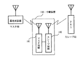
図1は、実施の形態1における中継局無線装置の構成例を示す図である。
図1において、中継局無線装置100(中継装置の一例である)は、マスタ局側無線装置101、スレーブ局側無線装置102を備えている。マスタ局側無線装置101は、基本となる基地局側中継局無線装置であり、マスタとする。スレーブ局側無線装置102は、マスタ局側無線装置101に接続される、中継する側の中継局無線装置であり、上記マスタに対するスレーブである。
【0015】
マスタ局側となる基地局装置は、前段の基地局側中継局無線装置であるマスタ局側無線装置101と無線区間で接続されており、またスレーブ局側となる移動局である移動体通信装置は、後段の中継局無線装置であるスレーブ局側無線装置102と接続されている。ここで、移動体通信装置としては、例えば、携帯電話、PHS(登録商標)等が挙げられる。
【0016】
中継局無線装置100は、移動体通信装置と基地局装置とを中継する。
第1の無線通信部の一例として、スレーブ局側無線装置102は、移動体通信装置との間で所定のデータを無線通信する。上記スレーブ局側無線装置102は、上記マスタ局側無線装置101により無線通信された所定のデータを入力し、入力された所定のデータを移動体通信装置との間で無線通信する。スレーブ局側無線装置102部は、TDMA/TDD方式を用いて上記移動体通信装置との間で所定のデータを無線通信する。ここで、所定のデータは、通話や音楽などの音声データ、画像データ等が一例として挙げられる。
第2の無線通信部の一例として、マスタ局側無線装置101は、上記第1の無線通信部の一例としてのスレーブ局側無線装置102により無線通信された所定のデータを入力し、入力された所定のデータを基地局装置との間で、上記第1の無線通信部の一例としてのスレーブ局側無線装置102とは独立して無線通信する。マスタ局側無線装置101は、同様に、TDMA/TDD方式を用いて上記基地局装置との間で所定のデータを無線通信する。
以上のように、本実施の形態では、TDMA/TDD方式の無線装置における、中継局の構成において、基準となる基地局側との送受信を行うマスタ局、当該マスタ局から見て中継する側をスレーブ局とし、それぞれ別の無線装置を割当てた複数局構成とする無線装置構成とした。
【0017】
この構成により、例えばマスタ局側は、システム的には、前段の無線装置であるマスタ局側無線装置101と、あたかもスレーブ局側が無いように、独自に動作可能である。また、スレーブ局側も後段の中継局無線装置であるスレーブ局側無線装置102と、システム的には、あたかも前段のマスタ局となる基地局が無いような動作が可能となる。
【0018】
例えば呼制御などの無線区間制御に関しても、マスタ局側となる基地局と無線通信するマスタ局側無線装置101と、スレーブ局側となる移動体通信装置と無線通信するスレーブ局側無線装置102とがそれぞれが独自に動作する事が可能となり、中継局無線装置として簡易な制御が可能となる。
【0019】
また、スロット構成についても、マスタ局側、スレーブ局側で別々の無線区間となるので、スロット構成も当然別のものとなり、従来のTDD中継局で必要であった、前段・後段のスロット干渉を無くす為のスロット配置も配慮せずにすむ。また、スロットの有効利用が可能となる。
【0020】
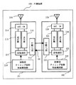
図2は、実施の形態1における中継局無線装置の内部構成例を示す図である。
図2において、マスタ局側無線装置101は、中継I/F(インターフェース)部213、切り換えスイッチ214、受信機215(受信部の一例である)、送信機216(送信部の一例である)、変復調部217、制御部218、アンテナ219を有している。同様に、スレーブ局側無線装置102は、中継I/F部223、切り換えスイッチ224、受信機225(受信部の一例である)、送信機226(送信部の一例である)、変復調部227、制御部228、アンテナ229を有している。インターフェース信号201は、マスタ局側無線装置101/スレーブ局側無線装置102間のインターフェース信号を表している。中継I/F部213、中継I/F部223は、本中継局無線装置のマスタ局/スレーブ局を接続するインターフェースを実現している。
【0021】
制御部218,228は、上記第1,2の無線通信部の一例であるマスタ局側無線装置101、スレーブ局側無線装置102の内、相手側の無線通信部とは別の呼制御をおこなう。制御部218,228は、それぞれ、タイミング制御、無線機制御をおこなう。
受信部の一例として、受信機215,225は、無線通信する所定のデータを受信する。
送信部の一例として、送信機216,226は、無線通信する所定のデータを送信する。
変復調部217は、上記受信機215により受信された所定のデータを復調し、上記送信機216により送信されるための所定のデータを変調する。変復調部227は、上記受信機225により受信された所定のデータを復調し、上記送信機226により送信されるための所定のデータを変調する。
インターフェース部の一例として、中継I/F部213は、上記変復調部217により復調された所定のデータを入力し、入力された所定のデータを上記第1,2の無線通信部の内、相手側の無線通信部となるスレーブ局側無線装置102とインターフェースを取りながら相手側の無線通信部となるスレーブ局側無線装置102に出力し、上記相手側の無線通信部となるスレーブ局側無線装置102から相手側の変復調部227により変調された所定のデータを上記相手側の無線通信部となるスレーブ局側無線装置102とインターフェースを取りながら入力し、入力された所定のデータを自己の上記変復調部217に出力する。同様に、インターフェース部の一例として、中継I/F部223は、上記変復調部227により復調された所定のデータを入力し、入力された所定のデータを上記第1,2の無線通信部の内、相手側の無線通信部となるマスタ局側無線装置101とインターフェースを取りながら相手側の無線通信部となるマスタ局側無線装置101に出力し、上記相手側の無線通信部となるマスタ局側無線装置101から相手側の変復調部217により変調された所定のデータを上記相手側の無線通信部となるマスタ局側無線装置101とインターフェースを取りながら入力し、入力された所定のデータを自己の上記変復調部227に出力する。
【0022】
本実施の形態では、複数局構成の無線機間にインターフェース装置を用い、無線機間の信号の送受信を行う構成とした。
このようなインターフェースを取る事により、従来の中継局構成とは違い、マスタ局側無線装置101/スレーブ局側無線装置102は、それぞれ、中継局無線装置ではなくあたかも1つの他の無線装置と同様の構成をとる事が可能となる。
【0023】
図3は、実施の形態1における中継局無線装置の無線周波数配置例を示す図である。
図3において、マスタ局側無線装置101は、マスタ局側無線周波数301であるf1を用い、スレーブ局側無線装置102はスレーブ局側無線周波数302であるf2を用いている。
上記第1の無線通信部の一例としてのスレーブ局側無線装置102は、上記第2の無線通信部の一例としてのマスタ局側無線装置101とは別の周波数f2を用いて上記移動体通信装置との間で所定のデータを無線通信する。
【0024】
本実施の形態では、複数局で構成する中継局において、それぞれの無線機に別周波数を割当て、互いの無線干渉を無くすと共に、自由なスロット割当てを行う事が可能となる構成とした。
この別周波数を設定する事により、従来の中継局で行っていた、周波数とスロットの干渉を防ぐ制御を行う必要がなく、マスタ局側無線装置101、スレーブ局側無線装置102とも別個の無線装置として、互いの周波数の干渉を気にせずに動作可能となる。
【0025】
以上のように中継局無線装置として、前段のマスタ局、後段のスレーブ局の複数無線装置構成とする事により、前段、後段のスロット構成の干渉が無く、自由なスロット構成が可能となり、あたかも別々の無線装置として動作する事が出来る。また無線装置として別々のものであるので、呼制御等の制御もそれぞれ独立して動作可能となる。
【0026】
実施の形態2.
図4は、実施の形態2における中継局無線装置のスレーブ局の複数並列接続例を示す図である。
図4において、中継局無線装置400(中継装置の一例である)は、マスタ局側無線装置401、スレーブ#0局側無線装置402、スレーブ#1局側無線装置403を備えている。スレーブ#1局側無線装置403は、マスタ局側無線装置401に対し、スレーブ#0局側無線装置402と並列に接続されたスレーブ#1局側の無線装置である。
マスタ局側無線装置401は、中継I/F部413、切り換えスイッチ214、受信機215(受信部の一例である)、送信機216(送信部の一例である)、変復調部217、制御部218、アンテナ219を有している。切り換えスイッチ214、受信機215(受信部の一例である)、送信機216(送信部の一例である)、変復調部217、制御部218、アンテナ219は、実施の形態1と同様である。
同様に、スレーブ#0局側無線装置402は、中継I/F部223、切り換えスイッチ224、受信機225(受信部の一例である)、送信機226(送信部の一例である)、変復調部227、制御部228、アンテナ229を有している。中継I/F部223、切り換えスイッチ224、受信機225(受信部の一例である)、送信機226(送信部の一例である)、変復調部227、制御部228、アンテナ229は、実施の形態1と同様である。
スレーブ#1局側無線装置403は、中継I/F部233、切り換えスイッチ234、受信機235(受信部の一例である)、送信機236(送信部の一例である)、変復調部237、制御部238、アンテナ239を有している。
中継I/F部213と中継I/F部223、中継I/F部213と中継I/F部233は、本中継局無線装置のマスタ局/スレーブ局を接続するインターフェースを実現している。
【0027】
中継装置の一例である中継局無線装置400は、移動体通信装置と基地局装置とを中継する。
複数の第1の無線通信部の一例であるスレーブ#0局側無線装置402とスレーブ#1局側無線装置403とは、それぞれ移動体通信装置との間で所定のデータを無線通信する。
第2の無線通信部の一例であるマスタ局側無線装置401は、上記複数の第1の無線通信部の各第1の無線通信部の一例であるスレーブ#0局側無線装置402(或いはスレーブ#1局側無線装置403)により無線通信された所定のデータを入力し、入力された所定のデータを基地局装置との間で、上記複数の第1の無線通信部の各第1の無線通信部の一例であるスレーブ#0局側無線装置402(或いはスレーブ#1局側無線装置403)とは独立して無線通信する。
上記複数の第1の無線通信部の一例であるスレーブ#0局側無線装置402とスレーブ#1局側無線装置403とは、並列に配置されている。
上記マスタ局側無線装置401は、上記並列に配置された複数の第1の無線通信部の各第1の無線通信部の一例であるスレーブ#0局側無線装置402(或いはスレーブ#1局側無線装置403)から所定のデータを入力する。
【0028】
制御部238は、上記マスタ局側無線装置401、スレーブ#1局側無線装置403の内、相手側の無線通信部とは別の呼制御をおこなう。制御部238は、それぞれ、タイミング制御、無線機制御をおこなう。
受信部の一例として、受信機235は、無線通信する所定のデータを受信する。
送信部の一例として、送信機236は、無線通信する所定のデータを送信する。
変復調部237は、上記受信機235により受信された所定のデータを復調し、上記送信機236により送信されるための所定のデータを変調する。変復調部237は、上記受信機235により受信された所定のデータを復調し、上記送信機236により送信されるための所定のデータを変調する。
インターフェース部の一例として、中継I/F部233は、上記変復調部237により復調された所定のデータを入力し、入力された所定のデータを相手側の無線通信部となるマスタ局側無線装置401とインターフェースを取りながら相手側の無線通信部となるマスタ局側無線装置401に出力し、上記相手側の無線通信部となるマスタ局側無線装置401から相手側の変復調部217により変調された所定のデータを上記相手側の無線通信部となるマスタ局側無線装置401とインターフェースを取りながら入力し、入力された所定のデータを自己の上記変復調部237に出力する。
【0029】
本実施の形態は、複数局に構成する中継局において、基地局側無線機であるマスタ局に対し、中継する側のスレーブ局を複数局、マスタ局に対し並列に接続する構成とした。そして、前述の複数スレーブ局を並列にマスタ局に接続した中継局装置において、それぞれ接続されたスレーブ局からの上り信号が発生した場合の制御として、中継局マスタ局側で、呼制御を行い、マスタ局に接続される上位無線装置から見て、マスタ局は、あたかも当該複数のスレーブ局が接続された無線装置ではなく、単一の無線装置であるように振舞う事を特徴とする。
マスタ局、スレーブ局それぞれが独自に無線装置として動作可能である為、スレーブ局側を並列に接続する事が可能である。従来の中継局の1:1中継ではなく、1:Nの中継が可能となる。
すなわち、中継局無線装置として、前段のマスタ局、後段のスレーブ局の複数無線装置構成とする事により、前段、後段のスロット構成の干渉が無く、自由なスロット構成が可能となり、あたかも別々の無線装置として動作する事が出来る。また無線装置として別々のものであるので、呼制御等の制御もそれぞれ独立して動作可能となる。これにより、スレーブ局側を複数並列に接続する事が可能となり、別々のエリアの中継動作を、単一中継局無線装置で実現する事ができる。
【0030】
実施の形態3.
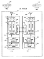
図5は、実施の形態3における中継局無線装置のマスタ局側従属同期とスレーブ局での同期とを切離した構成を示す図である。
図5において、中継局無線装置500(中継装置の一例である)は、マスタ局側無線装置510、スレーブ局側無線装置520を備えている。
マスタ局側無線装置510は、発振器503、中継I/F部213、切り換えスイッチ214、受信機215(受信部の一例である)、送信機216(送信部の一例である)、変復調部217、制御部218、アンテナ219を有している。中継I/F部213、切り換えスイッチ214、受信機215(受信部の一例である)、送信機216(送信部の一例である)、変復調部217、制御部218、アンテナ219は、実施の形態1と同様である。
スレーブ局側無線装置520は、発振器504、中継I/F部223、切り換えスイッチ224、受信機225(受信部の一例である)、送信機226(送信部の一例である)、変復調部227、制御部228、アンテナ229を有している。中継I/F部223、切り換えスイッチ224、受信機225(受信部の一例である)、送信機226(送信部の一例である)、変復調部227、制御部228、アンテナ229は、実施の形態1と同様である。
発振器503は、マスタ局側無線装置510の基準クロックを生成し、制御部218に出力する。
発振器504は、スレーブ局側無線装置520の基準クロックを生成し、制御部228に出力する。
上記TDMA/TDD方式は、スロット割り当てをおこなうことにより通信をおこなう。そして、上記第2の無線通信部の一例としてのマスタ局側無線装置510は、マスタ局側無線区間インターフェーススロット501を用いて無線通信する。上記第1の無線通信部の一例としてのスレーブ局側無線装置520は、マスタ局側無線装置510とは独立して割り当てられたスレーブ局側無線区間インターフェーススロット502を用いて上記移動体通信装置との間で所定のデータを無線通信する。
【0031】
本実施の形態は、従属同期システムで構成される無線装置において、中継局の基地局側を、従属同期構成としながら、中継されるスレーブ局を、新たに同期を取る基準局とし、当該中継局に無線にて接続される無線装置を、当該中継局に従属同期する構成とした。
従来は、中継局は、従属同期として動作しており、末端の端末まで従属同期される。本実施の形態により、マスタ局側は、通常の従属同期で動作するが、マスタ局とスレーブ局とのインターフェース部である中継I/F部213,223で信号のやりとりが行われる。そして、マスタ局/スレーブ局が別の無線装置として動作可能な為、スレーブ局側は、あたかもスレーブ局側無線装置520が、自身が基準となる基地局のように動作可能となる。よってスレーブ局後段の無線装置、例えば、移動体通信装置やPHS(登録商標)は、スレーブ局側無線装置520が基点となる従属同期を行う為、従来の中継局段数分、従属同期する必要がなくなる。
【0032】
【発明の効果】
本発明によれば、マスタ局側とスレーブ局側とがそれぞれが独自に動作する事が可能となり、中継局無線装置として簡易な制御を可能とすることができる。
【図面の簡単な説明】
【図1】実施の形態1における中継局無線装置の構成例を示す図である。
【図2】実施の形態1における中継局無線装置の内部構成例を示す図である。
【図3】実施の形態1における中継局無線装置の無線周波数配置例を示す図である。
【図4】実施の形態2における中継局無線装置のスレーブ局の複数並列接続例を示す図である。
【図5】実施の形態3における中継局無線装置のマスタ局側従属同期とスレーブ局での同期とを切離した構成を示す図である。
【符号の説明】
100 中継局無線装置、101 マスタ局側無線装置、102 スレーブ局側無線装置、213 中継I/F部、214 切り換えスイッチ、215 受信機、216 送信機、217 変復調部、218 制御部、219 アンテナ、223 中継I/F部、224 切り換えスイッチ、225 受信機、226 送信機、227 変復調部、228 制御部、229 アンテナ、233 中継I/F部、234 切り換えスイッチ、235 受信機、236 送信機、237 変復調部、238 制御部、239 アンテナ、301 マスタ局側無線周波数、302 スレーブ局側無線周波数、400 中継局無線装置、401 マスタ局側無線装置、402 スレーブ#0局側無線装置、403 スレーブ#1局側無線装置、413 中継I/F部、500 中継局無線装置、501 マスタ局側無線区間インターフェーススロット、502 スレーブ局側無線区間インターフェーススロット、503 発振器、504 発振器、510 マスタ局側無線装置、520 スレーブ局側無線装置。[0001]
TECHNICAL FIELD OF THE INVENTION
The present invention relates to a relay device and a relay method. In particular, the present invention relates to a relay wireless device and a relay method in a TDMA / TDD (Time Division Multiple Access / Time Division Duplex) wireless system.
[0002]
[Prior art]
A typical example of a conventional TDMA / TDD relay station radio apparatus is a cordless telephone system (PHS (Personal Handyphone System)) using one radio apparatus to switch an antenna switch in one radio apparatus. Relay operation. (For example, see Patent Document 1)
[0003]
[Patent Document 1]
JP 2000-165937 A [Patent Document 2]
JP 2000-134143 A [Patent Document 3]
Japanese Patent Application Laid-Open No. H10-25709
[Problems to be solved by the invention]
As described above, in the conventional relay station configuration, relaying is performed by one wireless device, and thus control of uplink and downlink signals is involved. As a result, there has been a problem that the slots cannot be freely arranged and the relay with two wireless devices cannot be performed at the same time.
[0005]
Also, when using the same frequency, interference with wireless devices before and after the relay became a problem.
[0006]
Further, in the method of synchronizing each wireless device including the relay station, it is premised that dependent synchronization with a high-order device is performed.
[0007]
An object of the present invention is to provide a configuration of a wireless relay system suitable for a TDMA / TDD wireless system.
[0008]
SUMMARY OF THE INVENTION It is an object of the present invention to simplify the call control by configuring the relay station wireless device with different wireless devices on the base station side and the relay side.
[0009]
In addition, by using a plurality of relay stations, each call control is separated, and the front and rear stages of the relay station are separated as wireless devices, and the front and rear slots can be freely arranged. The purpose is to do.
[0010]
It is another object of the present invention to reduce the interference between the relay stations by assigning a frequency to each of the plurality of relay stations.
[0011]
In addition, the synchronization method allows the base station side to perform subordinate synchronization while the relay side enables re-subordinate synchronization based on the relay station radio device, thereby suppressing the accuracy of the oscillator for each subordinate. The purpose is to enable.
[0012]
Another object of the present invention is to realize a 1: N relay instead of a 1: 1 relay by arranging a plurality of relay sides for wireless communication with a wireless device in parallel.
[0013]
[Means for Solving the Problems]
A relay device according to the present invention is a relay device that relays a mobile communication device and a base station device,
A first wireless communication unit wirelessly communicating predetermined data with the mobile communication device;
A predetermined data wirelessly communicated by the first wireless communication unit is input, and the input predetermined data is wirelessly communicated with a base station apparatus independently of the first wireless communication unit. And two wireless communication units.
[0014]
BEST MODE FOR CARRYING OUT THE INVENTION
FIG. 1 is a diagram illustrating a configuration example of a relay station wireless device according to the first embodiment.
In FIG. 1, a relay station radio apparatus 100 (an example of a relay apparatus) includes a master
[0015]
A base station apparatus serving as a master station is connected in a wireless section to a master
[0016]
Relay station radio apparatus 100 relays a mobile communication apparatus and a base station apparatus.
As an example of the first wireless communication unit, the slave station side
As an example of the second wireless communication unit, the master station
As described above, in the present embodiment, in the configuration of a relay station in a TDMA / TDD wireless device, a master station that performs transmission / reception with a reference base station side and a relay side viewed from the master station The wireless device has a configuration in which a plurality of slave stations are assigned and different wireless devices are assigned.
[0017]
With this configuration, for example, in terms of system, the master station side can independently operate as if there is no master station side
[0018]
For example, with respect to wireless section control such as call control, a master station
[0019]
Also, as for the slot configuration, since the master station side and the slave station side have different radio sections, the slot configuration naturally is also different, and the slot interference of the former stage and the latter stage, which is required in the conventional TDD relay station, is eliminated. There is no need to consider the slot arrangement to eliminate it. In addition, the slots can be effectively used.
[0020]
FIG. 2 is a diagram illustrating an example of an internal configuration of the relay station wireless device according to the first embodiment.
In FIG. 2, the master station
[0021]
The
As an example of the receiving unit, the
As an example of the transmission unit, the
The
As an example of the interface unit, the relay I /
[0022]
In this embodiment mode, an interface device is used between wireless devices having a plurality of stations to transmit and receive signals between wireless devices.
By adopting such an interface, unlike the conventional relay station configuration, each of the master station
[0023]
FIG. 3 is a diagram illustrating an example of a radio frequency arrangement of the relay station radio apparatus according to the first embodiment.
In FIG. 3, the master station
The slave station-
[0024]
In the present embodiment, in the relay station composed of a plurality of stations, a different frequency is allocated to each wireless device, thereby eliminating mutual radio interference and enabling free slot allocation.
By setting this separate frequency, there is no need to perform the control for preventing interference between the frequency and the slot, which is performed by the conventional relay station, and the master station
[0025]
As described above, as a relay station radio apparatus, by adopting a plurality of radio apparatuses including a master station at the preceding stage and a slave station at the subsequent stage, there is no interference between the slot configurations at the preceding stage and the subsequent stage, and a free slot configuration becomes possible. Can operate as a wireless device. Further, since the wireless devices are separate devices, control such as call control can be operated independently.
[0026]
Embodiment 2 FIG.
FIG. 4 is a diagram illustrating an example of a plurality of parallel connections of slave stations of the relay station wireless device according to the second embodiment.
In FIG. 4, a relay station radio apparatus 400 (an example of a relay apparatus) includes a master
The master station
Similarly, the
The
The relay I /
[0027]
Relay station radio apparatus 400, which is an example of a relay apparatus, relays between a mobile communication apparatus and a base station apparatus.
The
The master station-
The
The master station-
[0028]
The
As an example of the receiving unit, the
As an example of the transmitting unit, the
The
As an example of the interface unit, the relay I /
[0029]
In the present embodiment, in a relay station composed of a plurality of stations, a plurality of slave stations on the relay side are connected in parallel to the master station, which is a base station side radio, and the master station is connected in parallel. Then, in the relay station device in which the plurality of slave stations are connected to the master station in parallel, as a control when an uplink signal is generated from each connected slave station, call control is performed on the relay station master station side, When viewed from a higher-level wireless device connected to the master station, the master station behaves as if it were a single wireless device, not a wireless device to which the plurality of slave stations were connected.
Since each of the master station and the slave station can independently operate as a wireless device, it is possible to connect the slave stations in parallel. It is possible to perform 1: N relay instead of 1: 1 relay of the conventional relay station.
That is, the relay station radio apparatus has a plurality of radio apparatuses including a master station at the preceding stage and a slave station at the subsequent stage, so that there is no interference between the slot configurations at the preceding and subsequent stages, and a free slot configuration is possible. It can operate as a device. Further, since the wireless devices are separate devices, control such as call control can be operated independently. As a result, a plurality of slave stations can be connected in parallel, and relay operations in different areas can be realized by a single relay station wireless device.
[0030]
Embodiment 3 FIG.
FIG. 5 is a diagram showing a configuration in which the master station-side slave synchronization of the relay station wireless device and the synchronization at the slave station in the third embodiment are separated.
In FIG. 5, a relay station wireless device 500 (an example of a relay device) includes a master
The master station
The slave station-
The
The
In the TDMA / TDD system, communication is performed by allocating slots. Then, the master station
[0031]
In the present embodiment, in a wireless device configured with a slave synchronization system, while the base station side of the relay station has a slave synchronization configuration, the relayed slave station is used as a reference station for newly synchronizing, and The wireless device connected by radio is subordinately synchronized with the relay station.
Conventionally, the relay station operates as slave synchronization, and is slave-synchronized to the terminal at the end. According to the present embodiment, the master station operates in normal slave synchronization, but signals are exchanged in the relay I /
[0032]
【The invention's effect】
According to the present invention, the master station side and the slave station side can independently operate, and simple control as a relay station wireless device can be enabled.
[Brief description of the drawings]
FIG. 1 is a diagram illustrating a configuration example of a relay station wireless device according to a first embodiment.
FIG. 2 is a diagram showing an example of an internal configuration of a relay station radio apparatus according to the first embodiment.
FIG. 3 is a diagram showing an example of a radio frequency arrangement of the relay station radio apparatus according to the first embodiment.
FIG. 4 is a diagram illustrating an example of a plurality of parallel connections of slave stations of a relay station wireless device according to a second embodiment.
FIG. 5 is a diagram showing a configuration of a relay station radio apparatus according to a third embodiment in which master station side dependent synchronization and synchronization at a slave station are separated.
[Explanation of symbols]
Reference Signs List 100 relay station radio apparatus, 101 master station radio apparatus, 102 slave station radio apparatus, 213 relay I / F section, 214 switch, 215 receiver, 216 transmitter, 217 modulation / demodulation section, 218 control section, 219 antenna, 223 Relay I / F, 224 switch, 225 receiver, 226 transmitter, 227 modem, 228 controller, 229 antenna, 233 Relay I / F, 234 switch, 235 receiver, 236 transmitter, 237 Modulation / demodulation unit, 238 control unit, 239 antenna, 301 master station radio frequency, 302 slave station radio frequency, 400 relay station radio device, 401 master station radio device, 402
Claims (10)
移動体通信装置との間で所定のデータを無線通信する第1の無線通信部と、
上記第1の無線通信部により無線通信された所定のデータを入力し、入力された所定のデータを基地局装置との間で、上記第1の無線通信部とは独立して無線通信する第2の無線通信部と
を備えたことを特徴とする中継装置。In a relay device that relays the mobile communication device and the base station device,
A first wireless communication unit wirelessly communicating predetermined data with the mobile communication device;
A predetermined data wirelessly communicated by the first wireless communication unit is input, and the input predetermined data is wirelessly communicated with a base station apparatus independently of the first wireless communication unit. A relay device comprising: a second wireless communication unit.
上記第2の無線通信部は、TDMA/TDD(Time Division Multiple Access/Time Division Duplex)方式を用いて上記基地局装置との間で所定のデータを無線通信することを特徴とする請求項1記載の中継装置。The first wireless communication unit wirelessly communicates predetermined data with the mobile communication device using a TDMA / TDD (Time Division Multiple Access / Time Division Duplex) method,
2. The wireless communication unit according to claim 1, wherein the second wireless communication unit wirelessly communicates predetermined data with the base station apparatus using a TDMA / TDD (Time Division Multiple Access / Time Division Duplex) method. Relay device.
上記第1の無線通信部は、上記第2の無線通信部とは独立して割り当てられたスロットを用いて上記移動体通信装置との間で所定のデータを無線通信することを特徴とする請求項2記載の中継装置。In the TDMA / TDD system, communication is performed by allocating slots.
The first wireless communication unit wirelessly communicates predetermined data with the mobile communication device using a slot allocated independently of the second wireless communication unit. Item 3. The relay device according to Item 2.
上記第1,2の無線通信部は、共に、
無線通信する所定のデータを受信する受信部と、
無線通信する所定のデータを送信する送信部と、
上記受信部により受信された所定のデータを復調し、上記送信部により送信されるための所定のデータを変調する変復調部と、
上記変復調部により復調された所定のデータを入力し、入力された所定のデータを上記第1,2の無線通信部の内、相手側の無線通信部とインターフェースを取りながら相手側の無線通信部に出力し、上記相手側の無線通信部から相手側の変復調部により変調された所定のデータを上記相手側の無線通信部とインターフェースを取りながら入力し、入力された所定のデータを自己の上記変復調部に出力するインターフェース部と
をそれぞれ有することを特徴とする請求項1記載の中継装置。The first wireless communication unit inputs predetermined data wirelessly communicated by the second wireless communication unit, wirelessly communicates the input predetermined data with a mobile communication device,
The first and second wireless communication units are both
A receiving unit that receives predetermined data for wireless communication,
A transmission unit for transmitting predetermined data for wireless communication,
A modem that demodulates predetermined data received by the reception unit and modulates predetermined data to be transmitted by the transmission unit,
The predetermined data demodulated by the modem unit is input, and the input predetermined data is transmitted to the wireless communication unit of the other party while interfacing with the wireless communication unit of the other party among the first and second wireless communication units. And outputs predetermined data modulated by the other party's modem unit from the other party's wireless communication unit while interfacing with the other party's wireless communication unit. 2. The relay device according to claim 1, further comprising an interface unit that outputs to the modulation / demodulation unit.
移動体通信装置との間で所定のデータを無線通信する複数の第1の無線通信部と、
上記複数の第1の無線通信部の各第1の無線通信部により無線通信された所定のデータを入力し、入力された所定のデータを基地局装置との間で、上記複数の第1の無線通信部の各第1の無線通信部とは独立して無線通信する第2の無線通信部と
を備えたことを特徴とする中継装置。In a relay device that relays the mobile communication device and the base station device,
A plurality of first wireless communication units wirelessly communicating predetermined data with the mobile communication device;
The predetermined data wirelessly communicated by the first wireless communication units of the plurality of first wireless communication units is input, and the input predetermined data is exchanged with the base station apparatus by the plurality of first wireless communication units. A relay device comprising: a second wireless communication unit that performs wireless communication independently of each of the first wireless communication units of the wireless communication unit.
上記第2の無線通信部は、上記並列に配置された複数の第1の無線通信部の各第1の無線通信部から所定のデータを入力することを特徴とする請求項7記載の中継装置。The plurality of first wireless communication units are arranged in parallel,
The relay device according to claim 7, wherein the second wireless communication unit inputs predetermined data from each first wireless communication unit of the plurality of first wireless communication units arranged in parallel. .
第1の無線通信部が移動体通信装置との間で所定のデータを無線通信する第1の無線通信工程と、
第2の無線通信部が上記第1の無線通信工程により無線通信された所定のデータを入力し、第2の無線通信部が入力された所定のデータを基地局装置との間で、上記第1の無線通信工程とは独立して無線通信する第2の無線通信工程と
を備えたことを特徴とする中継方法。In a relay method performed by a relay device that relays a mobile communication device and a base station device,
A first wireless communication step in which the first wireless communication unit wirelessly communicates predetermined data with the mobile communication device;
The second wireless communication unit inputs the predetermined data wirelessly communicated in the first wireless communication step, and the second wireless communication unit transmits the input predetermined data to and from the base station device. A second wireless communication step of performing wireless communication independently of the first wireless communication step.
複数の第1の無線通信部の各第1の無線通信部が移動体通信装置との間で所定のデータを無線通信する複数の第1の無線通信工程と、
第2の無線通信部が上記複数の第1の無線通信工程の各第1の無線通信工程により無線通信された所定のデータを入力し、第2の無線通信部が入力された所定のデータを基地局装置との間で、上記複数の第1の無線通信工程の各第1の無線通信工程とは独立して無線通信する第2の無線通信工程と
を備えたことを特徴とする中継方法。In a relay method performed by a relay device that relays a mobile communication device and a base station device,
A plurality of first wireless communication steps in which each first wireless communication unit of the plurality of first wireless communication units wirelessly communicates predetermined data with a mobile communication device;
The second wireless communication unit inputs predetermined data wirelessly communicated in each first wireless communication step of the plurality of first wireless communication steps, and the second wireless communication unit converts the input predetermined data to predetermined data. A second wireless communication step of performing wireless communication with a base station apparatus independently of the first wireless communication steps of the plurality of first wireless communication steps. .
Priority Applications (1)
| Application Number | Priority Date | Filing Date | Title |
|---|---|---|---|
| JP2003017976A JP2004229242A (en) | 2003-01-27 | 2003-01-27 | Repeating apparatus and repeating method |
Applications Claiming Priority (1)
| Application Number | Priority Date | Filing Date | Title |
|---|---|---|---|
| JP2003017976A JP2004229242A (en) | 2003-01-27 | 2003-01-27 | Repeating apparatus and repeating method |
Publications (1)
| Publication Number | Publication Date |
|---|---|
| JP2004229242A true JP2004229242A (en) | 2004-08-12 |
Family
ID=32904982
Family Applications (1)
| Application Number | Title | Priority Date | Filing Date |
|---|---|---|---|
| JP2003017976A Withdrawn JP2004229242A (en) | 2003-01-27 | 2003-01-27 | Repeating apparatus and repeating method |
Country Status (1)
| Country | Link |
|---|---|
| JP (1) | JP2004229242A (en) |
Cited By (6)
| Publication number | Priority date | Publication date | Assignee | Title |
|---|---|---|---|---|
| JP2009302694A (en) * | 2008-06-11 | 2009-12-24 | Hitachi Ltd | Radio communication network system |
| JP2010507990A (en) * | 2006-10-25 | 2010-03-11 | インテル・コーポレーション | Station grouping algorithm for multi-phase transmission for multi-hop wireless broadband access communication |
| JP2013070402A (en) * | 2007-03-10 | 2013-04-18 | Lingna Holdings Private Limited Liability Company | Method of optimizing downlink throughput with user cooperation and scheduling in adaptive cellular networks |
| CN107864002A (en) * | 2017-12-20 | 2018-03-30 | 成都芯通软件有限公司 | A kind of repeater remote termination |
| CN108023634A (en) * | 2017-12-20 | 2018-05-11 | 成都芯通软件有限公司 | A kind of chain type cascades TD-LTE frequency-shift repeater station systems |
| WO2018199461A1 (en) * | 2017-04-28 | 2018-11-01 | 주식회사 케이티 | Radio relay apparatus and operating method therefor |
-
2003
- 2003-01-27 JP JP2003017976A patent/JP2004229242A/en not_active Withdrawn
Cited By (8)
| Publication number | Priority date | Publication date | Assignee | Title |
|---|---|---|---|---|
| JP2010507990A (en) * | 2006-10-25 | 2010-03-11 | インテル・コーポレーション | Station grouping algorithm for multi-phase transmission for multi-hop wireless broadband access communication |
| JP2013070402A (en) * | 2007-03-10 | 2013-04-18 | Lingna Holdings Private Limited Liability Company | Method of optimizing downlink throughput with user cooperation and scheduling in adaptive cellular networks |
| JP2009302694A (en) * | 2008-06-11 | 2009-12-24 | Hitachi Ltd | Radio communication network system |
| WO2018199461A1 (en) * | 2017-04-28 | 2018-11-01 | 주식회사 케이티 | Radio relay apparatus and operating method therefor |
| JP2020519099A (en) * | 2017-04-28 | 2020-06-25 | ケーティー コーポレーション | Wireless relay device and operating method thereof |
| US10985830B2 (en) | 2017-04-28 | 2021-04-20 | Kt Corporation | Radio relay apparatus and operating method therefor |
| CN107864002A (en) * | 2017-12-20 | 2018-03-30 | 成都芯通软件有限公司 | A kind of repeater remote termination |
| CN108023634A (en) * | 2017-12-20 | 2018-05-11 | 成都芯通软件有限公司 | A kind of chain type cascades TD-LTE frequency-shift repeater station systems |
Similar Documents
| Publication | Publication Date | Title |
|---|---|---|
| EP1924107B1 (en) | Integrating communication networks | |
| CN100373970C (en) | Call control apparatus and method for dual-mode mobile terminals | |
| JPH10247874A (en) | Time-division duplex system portable telephone repeater | |
| CN108834000B (en) | Relay method and device | |
| CN101515818A (en) | FDD inband backhauling and method thereof | |
| CN100515106C (en) | Wireless communication method, wireless communication system using the same, and wireless terminal thereof | |
| JPH04234233A (en) | Communication method, communication apparatus, transmitting/receiving site appararus and moving wireless transmitting/ receiving site apparatus | |
| JP2008118337A (en) | Wireless communication system, wireless communication method, and terminal | |
| JP2010050971A (en) | Method and apparatus for operating wireless communications system | |
| ATE515853T1 (en) | IMPROVEMENTS TO SYNCHRONIZATION PROCEDURES FOR SINGLE FREQUENCY SIMULCAST CELLULAR COMMUNICATIONS NETWORKS | |
| JP2004229242A (en) | Repeating apparatus and repeating method | |
| JP2012227872A (en) | Communication system | |
| CN101631276A (en) | Repeater and follow-up notification method after broadcast communication thereof | |
| WO2023025158A1 (en) | Intercom relay base station | |
| KR100243028B1 (en) | Method and apparatus for communicating between subscribers of cordless phone | |
| JP4569770B2 (en) | Wireless communication method, wireless communication system, and wireless base station | |
| JPH0897762A (en) | Repeater for mobile communication | |
| KR20010082230A (en) | Mobile radio telephone system and a mobile station | |
| US20180069623A1 (en) | Apparatus for direct communication by mobile terminals | |
| JP5425176B2 (en) | Wireless communication system, wireless communication apparatus, and wireless communication method | |
| CN111093170A (en) | Vehicle-mounted sucker radio station and ad hoc network radio station system | |
| JP2000165937A (en) | Radio repeating device/method | |
| JP2003218733A (en) | Short-distance radio transmitting equipment | |
| JP2008245228A (en) | Radio communication system | |
| JP3192870B2 (en) | Cordless telephone |
Legal Events
| Date | Code | Title | Description |
|---|---|---|---|
| RD04 | Notification of resignation of power of attorney |
Free format text: JAPANESE INTERMEDIATE CODE: A7424 Effective date: 20040519 |
|
| RD04 | Notification of resignation of power of attorney |
Free format text: JAPANESE INTERMEDIATE CODE: A7424 Effective date: 20041025 |
|
| A621 | Written request for application examination |
Free format text: JAPANESE INTERMEDIATE CODE: A621 Effective date: 20050926 |
|
| A761 | Written withdrawal of application |
Free format text: JAPANESE INTERMEDIATE CODE: A761 Effective date: 20070611 |