JP2004220560A - Maintenance system for electronic device - Google Patents
Maintenance system for electronic device Download PDFInfo
- Publication number
- JP2004220560A JP2004220560A JP2003372898A JP2003372898A JP2004220560A JP 2004220560 A JP2004220560 A JP 2004220560A JP 2003372898 A JP2003372898 A JP 2003372898A JP 2003372898 A JP2003372898 A JP 2003372898A JP 2004220560 A JP2004220560 A JP 2004220560A
- Authority
- JP
- Japan
- Prior art keywords
- status information
- central server
- data
- remote maintenance
- server
- Prior art date
- Legal status (The legal status is an assumption and is not a legal conclusion. Google has not performed a legal analysis and makes no representation as to the accuracy of the status listed.)
- Pending
Links
Images


Classifications
-
- G—PHYSICS
- G06—COMPUTING; CALCULATING OR COUNTING
- G06Q—INFORMATION AND COMMUNICATION TECHNOLOGY [ICT] SPECIALLY ADAPTED FOR ADMINISTRATIVE, COMMERCIAL, FINANCIAL, MANAGERIAL OR SUPERVISORY PURPOSES; SYSTEMS OR METHODS SPECIALLY ADAPTED FOR ADMINISTRATIVE, COMMERCIAL, FINANCIAL, MANAGERIAL OR SUPERVISORY PURPOSES, NOT OTHERWISE PROVIDED FOR
- G06Q10/00—Administration; Management
- G06Q10/06—Resources, workflows, human or project management; Enterprise or organisation planning; Enterprise or organisation modelling
-
- G—PHYSICS
- G06—COMPUTING; CALCULATING OR COUNTING
- G06Q—INFORMATION AND COMMUNICATION TECHNOLOGY [ICT] SPECIALLY ADAPTED FOR ADMINISTRATIVE, COMMERCIAL, FINANCIAL, MANAGERIAL OR SUPERVISORY PURPOSES; SYSTEMS OR METHODS SPECIALLY ADAPTED FOR ADMINISTRATIVE, COMMERCIAL, FINANCIAL, MANAGERIAL OR SUPERVISORY PURPOSES, NOT OTHERWISE PROVIDED FOR
- G06Q10/00—Administration; Management
- G06Q10/10—Office automation; Time management
Landscapes
- Engineering & Computer Science (AREA)
- Business, Economics & Management (AREA)
- Human Resources & Organizations (AREA)
- Strategic Management (AREA)
- Entrepreneurship & Innovation (AREA)
- Economics (AREA)
- Operations Research (AREA)
- Theoretical Computer Science (AREA)
- General Physics & Mathematics (AREA)
- Marketing (AREA)
- General Business, Economics & Management (AREA)
- Quality & Reliability (AREA)
- Tourism & Hospitality (AREA)
- Physics & Mathematics (AREA)
- Development Economics (AREA)
- Educational Administration (AREA)
- Game Theory and Decision Science (AREA)
- Data Mining & Analysis (AREA)
- Computer And Data Communications (AREA)
- Management, Administration, Business Operations System, And Electronic Commerce (AREA)
- Accessory Devices And Overall Control Thereof (AREA)
Abstract
Description
本発明は、電子装置の遠隔保守(remote maintenance)に関する。 The present invention relates to remote maintenance of electronic devices.
プリンタ、複写機、及びスキャナなどの電子装置に対する保守の提供が知られている。オフィス環境には、何種類もの電子装置が存在し、これらの装置に対して1社以上の保守会社が保守サービスを提供していることもある。これらのうちの1台が、専門家のサポートを必要とする障害が識別されるときには、関連する保守会社にサービスコールをかける。 It is known to provide maintenance for electronic devices such as printers, copiers, and scanners. In an office environment, there are many types of electronic devices, and one or more maintenance companies may provide maintenance services for these devices. One of these will make a service call to the associated maintenance company when a fault requiring expert assistance is identified.
図1はサービスコールを処理する典型的な構成を示す。図1の構成は、顧客2、コール入力オペレータ4、ディスパッチャ6、及びエンジニア8を含む。
FIG. 1 shows a typical configuration for processing a service call. The configuration of FIG. 1 includes a
顧客2は、電話をかけて電子装置の障害をコール入力オペレータ4に報告する。例えば、顧客は複写機の動作が停止し、エラーメッセージを表示していると報告する。コール入力オペレータ4は、発信者の氏名、障害のある装置のID、及びエラーメッセージのメモを含む障害の詳細などの情報を記録することによって通話のログを残す。この場合、発信者には、そのジョブ参照を与えるようにしても良い。
コール入力オペレータ4が記録した情報はデータベース上に記録される。このデータベースにはディスパッチャ6がアクセスする。ディスパッチャ6はその障害を査定し、適切な処置を取る。ここで必要とされる処置は、自力で障害を復旧する方法を顧客2に説明することであっても良い。あるいは、顧客の元へエンジニア8を派遣することであっても良い。ここで、ディスパッチャ6は、コール入力オペレータ4と同一人物であっても良い。
Information recorded by the call input operator 4 is recorded on a database. The dispatcher 6 accesses this database. Dispatcher 6 assesses the fault and takes appropriate action. The action required here may be to explain to the
図1のサービス構成の問題点は、顧客2が障害を検出してコール入力オペレータ4に報告しない限りサポートが受けられないことである。障害の報告が遅れ、障害への対処が可能になるまで、例えば、エンジニア8が顧客2の元へ到着するまでに更に遅れることは必至であろう。この間、その装置は使用不可能となる可能性が高い。
The problem with the service configuration of FIG. 1 is that no support is available unless the
図1のサービス構成の更なる問題点は、顧客2は障害の発生後にならないと報告することができないことである。つまり、顧客2は潜在的(potential)な障害を監視する手段を持たない。障害を予測することができ、発生前に処置を取ることができるならば、装置の故障を防止することができる。更に、障害の発生前に処理することによって、時には損傷を与えるような紙詰まりなどの障害を回避することができる。損傷を受けた装置の修理に要する費用は、障害の発生を防止するのにかかる費用よりも格段に高い可能性がある。
A further problem with the service configuration of FIG. 1 is that
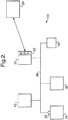
図2は、上述の障害に対処するために開発された既知の保守システム(符号10で示される)を示す。このシステムは、第1の電子装置12、第2の電子装置14、及び第3の電子装置16を含む。これらの装置は複写機、プリンタ、又はスキャナなどであっても良い。システムは、クライアントコンピュータ18及びサーバコンピュータ20を更に含む。遠隔故障診断ソフトウェア22は、サーバコンピュータ20と関連付けられている。遠隔故障診断ソフトウェア22は、以降、略語のRDSを用いて呼ぶこととする。サーバ20は、遠隔バックエンド24(サービス管理コンピュータシステムとも呼ばれる)に電子的に接続される。
FIG. 2 shows a known maintenance system (indicated by reference numeral 10) developed to address the above-mentioned obstacles. The system includes a first electronic device 12, a second
電子装置12、14、及び16、クライアントコンピュータ18、及びサーバ20の全てはローカルネットワークバス26を用いて接続されている。装置12、14、及び16のステータスに関する情報をサーバ20が回収する。この情報に基づいてRDS22の制御を受けながら、サーバ20はクライアントコンピュータ18及びバックエンド24と通信を行なう。
All of the
バックエンド24は、装置12、14、及び16の保守を担当する機構である。バックエンド24は、RDS22により提供されるデータを受信すると、これに応じた処置(アクションン)を開始することができる。すなわち、バックエンド24は、図1のコール入力オペレータ4及びディスパッチャ6の機能を実行するので、顧客はコール入力オペレータに電話をかける必要がない。
The
図2の例において、装置12及び16はデジタルステータス情報を提供することが可能なデジタル装置であり、この情報はバス26を介して収集することができる。実際には、ステータス情報の送信は、RDSが装置をポーリングし、それに応答する形で行なわれる。装置14はこの機能を持たないアナログ装置である。装置14には直接アクセス機構28が備わっており、装置14のステータスに関するアナログ情報をバス26を介してアクセス可能なデジタルデータへと変換する。
In the example of FIG. 2,
バス26を介して収集可能なデータには、用紙及びトナーの量の示度、紙詰まり(ジャム)、エラー又はアラーム、部品数(parts conters)、用紙使用情報、装置使用情報、装置に取り付けられている機器(文書フィーダなど)、及び装置にインストールされているソフトウェアが含まれる。
Data that can be collected via the
RDSは複数の機能を実行する。この機能には、接続している装置のステータスの監視、装置に関するデータの格納及び分析、障害及び潜在的な障害の顧客及び/又はバックエンドへの通知、及び用紙及びトナーなどの消耗品の使用状況の探知が含まれる。 The RDS performs several functions. This includes monitoring the status of connected devices, storing and analyzing data about the devices, notifying customers and / or backends of faults and potential faults, and using consumables such as paper and toner. Includes situation detection.
RDS22は、2つの異なる条件の下、すなわち、イベントデータとして又は定期データとしてバックエンド24にデータを送信することができる。イベントデータは、RDSがイベントを検出するか、あるいは、一定の条件又は閾値が満たされると送信される。定期データは、毎週(例えば、毎週月曜日の0時30分)又は毎月(例えば、毎月28日の0時30分)などの一定の間隔で送信される。
The
収集される定期データは、例えば、装置内の部品の予想寿命に関する情報を含む。 The collected periodic data includes, for example, information on the expected life of the components in the device.
先ず、イベントデータについて考察する。RDS22は、様々なクラスのイベントをそれぞれ異なった方法で処理する。最も重大なイベントは装置の動作を妨げるイベントであり、これを「エラー」と呼ぶ。装置の動作を妨げない重大なイベントは「アラーム」を発する。「アラーム」には深刻な性質のものがあり、その場合、バックエンド24への迅速な通知が必要である。深刻でない性質のものもあるが、その場合でも再発する可能性が高い。例えば、エラーとしては紙詰まり、アラームとしてはトナー残量の僅少がある。
First, consider event data. The
RDSは各装置12、14、及び16を監視し、いずれかの装置が動作を停止するとエラーが識別される。RDSがエラーを検出すると、クライアントコンピュータ18及びバックエンド24の双方がその通知を受ける。(尚、クライアントコンピュータ及びサーバコンピュータは1台の同じ装置であっても良い。)
本質的に、エラーには顧客が復旧可能なものとエンジニアの派遣が必要なものとの2種類がある。エラーへの対応はバックエンド24により判定される。エラーメッセージを受信すると、関連する装置のステータスを調べ、適切な処置を取ることができる。場合によって、エンジニアを装置の設置場所へ派遣する必要、あるいは、顧客と連絡を取って顧客自身が実行可能な手順を説明する必要が生じる。いずれの選択肢が実施される場合でも、顧客がエラーに気づくのを待つのではなく、バックエンド24が主導権を取ることができる。
The RDS monitors each
Essentially, there are two types of errors: those that can be recovered by the customer and those that require the dispatch of an engineer. The response to the error is determined by the
また、RDSは、装置12、14、及び16において、動作を妨げない重大なイベント又は潜在的に重大なイベントの発生を監視する。上述のように、このようなイベントをアラーム状態と呼ぶ。RDSがアラーム状態を検出すると、バックエンド24は通知を受けるが、顧客には通知されない。これは、当該装置が動作中であり、クライアントは障害の可能性があることを認識する必要がないからである。障害があることに顧客が気づく前に、バックエンド24は上述のように適切な処置を取ることができる。これにより、当該装置の休止時間を最小限にして潜在的に重大な障害を防止することができるであろう。
The RDS also monitors
RDSの使用により、保守部門は事前に処置を取ることが可能になる。例えば、アラーム状態は、障害が近い将来に発生する可能性が高いことを示すかもしれない。この場合、障害発生前に保守処置を取ることが可能になり、機械類の休止時間及び損傷を減少させる結果となる。 The use of RDS allows the maintenance department to take proactive action. For example, an alarm condition may indicate that a fault is likely to occur in the near future. In this case, maintenance actions can be taken before a failure occurs, resulting in reduced downtime and damage to the machinery.
上述のシステムは、バックエンドが1つしかない場合でも十分に機能するが、必ずしもこの構成でなくても良い。システムの多様な顧客をサポートする複数の異なる保守機構があっても良い。この異なる機構は、異なるサービスバックエンド(以降、「サービス管理システム」と呼ぶ)を有するものと想定される。 The above system works well with only one backend, but need not be of this configuration. There may be a number of different maintenance mechanisms supporting various customers of the system. The different mechanisms are assumed to have different service back ends (hereinafter referred to as "service management systems").
この場合、異なるサービス管理システムは、RDSにより送信されるデータを理解・格納することが可能なように、修正したり、あるいは、特別なアプリケーションを備えたりする必要がある。 In this case, different service management systems need to be modified or provided with special applications so that they can understand and store the data transmitted by the RDS.
この実現は可能であるが、費用がかさむ可能性がある。 This is possible, but can be expensive.
このような問題は、複数の国家にまたがって保守システムが実施されており、各国に少なくとも1つの異なるサービス管理システムが提供されている場合に起こる。 Such a problem occurs when a maintenance system is implemented across a plurality of countries and each country is provided with at least one different service management system.
更に、各サービス管理システムにおいて、RDSから受信したデータを処理(例えば、データのデータベースへの格納又はデータに基づく処置)する必要が生じるであろう。これが費用を倍増させることになる。 Further, at each service management system, it may be necessary to process the data received from the RDS (eg, storing the data in a database or taking action based on the data). This will double costs.
本発明の目的は、上述の問題のうちの少なくとも一部に対処する電子保守システムを提供することである。 It is an object of the present invention to provide an electronic maintenance system that addresses at least some of the above-mentioned problems.
本発明によると、遠隔保守データシステムにおいて、
不定期の保守を必要とする複数の電子装置に関するステータス情報を受信するように構成される中央サーバであって、前記ステータス情報が前記装置から前記中央サーバへと直接に、あるいは、1台以上の中間装置を介して送信される中央サーバと、
前記中央サーバと通信するウェブサーバとを具備し、
前記中央サーバは、前記ステータス情報に基づく情報を含み、ハイパーテキストリンクから構成されるメッセージを特定の電子装置に関連するエンティティへと送信するように更に構成され、
前記ウェブサーバは、少なくとも前記特定の電子装置に関連する前記ステータス情報へのアクセス権を有し、前記リンクが活動化されるのに応じて前記ステータス情報を提供するように構成される遠隔保守データシステムを提供する。
According to the present invention, in a remote maintenance data system,
A central server configured to receive status information for a plurality of electronic devices that require irregular maintenance, wherein the status information is sent directly from the device to the central server, or to one or more devices. A central server transmitted via the intermediate device;
A web server that communicates with the central server,
The central server is further configured to include a message based on the status information and to send a message comprising a hypertext link to an entity associated with a particular electronic device;
The web server has at least access to the status information associated with the particular electronic device, and remote maintenance data configured to provide the status information in response to the link being activated. Provide system.
また、本発明によると、不定期の保守を必要とする複数の電子装置のインタフェーシング方法において、
前記装置から中央サーバへと直接に、あるいは、1台以上の中間装置を介してステータス情報を送信し、
前記ステータス情報に基づく情報を含み、ハイパーテキストリンクから構成されるメッセージを特定の電子装置に関連するエンティティへと送信し、
少なくとも前記特定の電子装置に関連する前記ステータス情報へのアクセス権を有し、前記リンクの活動化に応じて前記ステータス情報を提供するウェブサーバを提供する構成のインタフェーシング方法を提供する。
Further, according to the present invention, in a method for interfacing a plurality of electronic devices requiring irregular maintenance,
Sending status information directly from said device to a central server or via one or more intermediate devices,
Sending a message comprising hypertext links to an entity associated with a particular electronic device, including information based on said status information,
There is provided an interfacing method configured to provide a web server that has at least an access right to the status information related to the specific electronic device and provides the status information in response to activation of the link.
本発明によれば、異なるシステム間でのインタフェーシングの場合、ハイパーテキストリンクを用いたメッセージを提供する方法が簡単である。このメッセージは中央サーバにあるメールサーバにより容易に生成することができる。その送信先であるエンティティは、ハイパーテキストリンクを容易に活動化し、装置の障害の性質を確認する際に必要であろう詳細なステータス情報をアクセスすることができる。この機構により、異なるデータ及び制御システムを用いる異なる保守機構が全て中央サーバに接続される場合に起こり得る問題が減少する。 According to the present invention, in the case of interfacing between different systems, a method for providing a message using a hypertext link is simple. This message can be easily generated by a mail server located at a central server. The destination entity can easily activate the hypertext link and access the detailed status information that may be needed in determining the nature of the device failure. This mechanism reduces the problems that can occur if different maintenance mechanisms using different data and control systems are all connected to the central server.
一例として、添付の図面を参照しながら本発明の実施例を説明する。 By way of example, embodiments of the present invention will be described with reference to the accompanying drawings.
図3は、複数のクライアント26、28、30、32、34、36、38、40、42、44、46、及び48と、複数の保守機構(maintenance organisations)52、54、及び56を有する本発明のシステムを示す。各クライアントは中央サーバ50と通信を行ない、中央サーバは保守機構52、54、及び56の各々と通信を行なう。各クライアントは、少なくとも1つの保守機構と関連付けられており、サーバ50を介して適切な保守機構と通信を行なう。必要があれば、クライアントは異なる保守機構に異なる種類のイベントデータ又は定期データを送信したり、あるいは、異なる装置に関して異なる保守機構と通信を行なったりすることができるであろう。
FIG. 3 shows a book with a plurality of
図2及び図3を参照する。複数のクライアント26、28、30、32、34、36、38、40、42、44、46、及び48の各々は、図2の装置12、14、及び16などの電子装置を含んでも、クライアントコンピュータ18及びRDS22を含むサーバ20を含んでも良い。図1のバックエンド24は、クライアントが関連付けられる保守機構に対応する。中央サーバ50はクライアントが保守機構と通信する際に媒介する手段である。
Please refer to FIG. 2 and FIG. Each of the plurality of
図4は、本発明のシステムを使用して装置12の障害に対処する方法を示す。図4は、図2の例のように電気装置12、クライアントコンピュータ18、及びRDS22を有するサーバ20を含むクライアント26を示す。クライアント26は、保守機構コールセンタ58及びディスパッチシステム60を含む保守機構52と中央サーバ50を介して通信を行なう。ディスパッチシステム60は、エンジニア62と通信を行なう。エンジニア62は、クライアントを訪問して障害のある装置12を修理することができる。
FIG. 4 illustrates how the system of the present invention can be used to handle a failure of device 12. FIG. 4 illustrates a
RDS22は、先に概説したように装置12を監視する。障害が検出されると、RDS22によりサーバ50を介して関連する保守機構に通知される。障害の種類によっては、先に説明したようにクライアントコンピュータ18にも通知される。保守機構において、コールセンタ58は通話のログを残し、ディスパッチシステム60が必要な処置を取る。この処置は、エンジニア62を現場に派遣することを必要とするかもしれない。
データは、様々な方法でRDS22から中央サーバ50へと転送されても良い。例えば、インターネットを介したTCP/IP又は電子メールであっても、直通の電話接続又は無線接続を使用しても良い。以下の例では、電子メールの使用を想定することとする。
Data may be transferred from
図5は、クライアント26が中央サーバ50を介して保守機構52と通信を行なう際に使用するシステムを詳細に示している。クライアント26は、図2及び図4に示すように電子装置12、クライアントコンピュータ18、及びRDS22を有するサーバ20を含む。中央サーバ50は、第1のメールサーバ64、パーサ66、メッセージコンポーザ67、第2のメールサーバ68、データベース70、ウェブポータル72、及びMQメールサーバ73を具備する。保守機構52は、メールサーバ74、サーバネットワーク76、MQメールサーバ77、ブリッジングシステム79、及びサービス管理システム(SMS)96を具備する。
FIG. 5 shows the system used when the
RDS22が保守機構52と通信を行なう場合、RDS22は中央サーバ50の第1のメールサーバ64に電子メールを送信する。第1のメールサーバ64が受信した電子メールは、第2のメールサーバ68(メッセージコンポーザ67を介する)及びデータベース70に渡される前にパーサ66により解析される。第2の電子メールが中央サーバ50の第2のメールサーバ68から保守機構52のメールサーバ74へと送信される。情報は、メールサーバ74から保守機構サーバネットワーク76へと渡されるが、端末78、80、82、及び84のいずれか1台を介してアクセスすることができる。端末78、80、82、及び84のうちの1台(図5の例では端末84)で作業中のユーザは、このサーバ端末で表示される情報をサービス管理システム96へと転送する。(サービス管理システムは、クライアント、電子装置、部品、消耗品、及びエンジニアの可用性などに関する情報を含むことができる。)サービス管理システムは、保守機構にメッセージを送信する原因となった障害を復旧するための処置(例えば、必要に応じてエンジニアをクライアントの現場に派遣)を実施する。
When the
保守機構側のユーザは、2つの別々のデータシステムへのアクセス権を有することができる。1つは中央サーバ50により提供されるデータシステムであり、もう1つは保守機構のローカルサービス管理システム96により提供されるデータシステムである。勿論、ユーザは、別々のプログラムを実行する1台の端末を有することで2つのシステムのデータをアクセスすることもできる。
The user at the maintenance facility may have access to two separate data systems. One is a data system provided by the
本例では、ユーザは電子メールクライアントを使用して中央サーバ50の情報をアクセスし、中央サーバ50によりメールサーバ74に送信されたメッセージを読む。ユーザは、障害の情報を入手可能でなければならない。ユーザは、ウェブポータル72により中央サーバから必要な詳細を全て取得することができる。
In this example, a user accesses information at
このアーキテクチャを使用すると、保守機構の各ユーザが(中央サーバ50を介して)RDS22の情報へのアクセス権を有しながらも、各保守機構に対するサービス管理システムインタフェースに別々の電子RDSを提供する問題は回避される。また、提供されるインタフェースは簡易なものであるので、いかなるサービス機構のシステムでも容易に対応することができる。更に、サービス管理システムの特定の機能は、RDSから得られる全てのデータに適切に対応することができないが、電子装置及びその障害に関するあらゆる情報は中央サーバに収容される。 With this architecture, the problem of providing a separate electronic RDS to the service management system interface for each maintenance facility, while each user of the maintenance facility has access to the information of the RDS 22 (via the central server 50). Is avoided. Further, since the provided interface is simple, any service mechanism system can easily cope with it. In addition, certain functions of the service management system cannot adequately handle all data obtained from the RDS, but all information regarding the electronic device and its faults is contained in a central server.
図5の例示のシステムの動作の更なる詳細は以下の通りである。 Further details of the operation of the example system of FIG. 5 are as follows.
上述のように、図5の例では、RDS22が保守機構52と通信を行なう場合、RDS22から中央サーバ50の第1のメールサーバ64へと電子メールが送信される。この電子メールは本文及び添付ファイルから構成される。RDSからメールサーバ64に送信される電子メールの本文は、対象のRDSを識別するものであり、送信されるデータに関する汎用的なコード化情報のみを提供する。データ自体は添付ファイルに含まれる。
As described above, in the example of FIG. 5, when the
RDS22とメールサーバ64との間の通信は、メールサーバ64からRDS22へのアクノリッジ信号の送信を除いては単方向である(アクノリッジが受信されない場合、RDSは時間をおいてメッセージの再送信を試みる)。
Communication between the
メールサーバ64は、電子メールの添付ファイルに含まれるデータをパーサ66に渡す。データは解析され、解析後のデータはデータベース70に格納される。また、この情報から(メッセージコンポーザ67によって)新規の電子メールメッセージが作成され、第2のメールサーバ68へと渡される。第2のメールサーバ68は、電子メールメッセージを関連する保守機構へと回送する。どの保守機構が関連するかは、データベース中の情報から判定することができる。この情報は、通常、その保守機構に対して責任があることが明確に記録されている当のRDSによるものである。関連する保守機構は、後述するように、RDSからのメッセージ中の情報(送信先アドレスに含めることが可能)から判定することができる。
The mail server 64 passes data included in the attached file of the e-mail to the
受信されたイベントデータは直ちに保守機構へと回送される。 The received event data is immediately forwarded to the maintenance facility.
別の実施形態では、イベントデータの一部をデータベースに格納した後、しばらく送信を延期しても良い。イベントデータは、回送する前に他のイベントデータと共に集めることができるであろう。 In another embodiment, transmission may be postponed for some time after some of the event data is stored in the database. Event data could be collected with other event data before forwarding.
別の実施形態では、一定の条件が満たされた場合のみ、保守機構はイベントデータの通知を受ける。この条件は、データベースに格納されるパラメータとして定義することができる。例えば、消耗品(トナーなど)が交換されたことを示す「消耗品の交換(consumables replacement)」イベントは、直ちに中央サーバ50に転送される。ユーザが消耗品のストックを有する場合、保守機構はそのストックが限界レベルに到達したときのみメッセージを受信することを望むであろう。従って、中央サーバ50は、同じRDSに関連する全ての「消耗品交換」イベントをデータベース中に格納し、一定数の「消耗品交換」イベントを受信し次第、関連する保守機構にメッセージを送信する。この好適な例では、中央サーバが同じRDSから幾つの「消耗品交換」イベントを受信した後に関連する機構に通知すべきであるかを指定する閾値として条件をデータベース中に定義することができる。
In another embodiment, the maintenance mechanism is notified of the event data only if certain conditions are met. This condition can be defined as a parameter stored in the database. For example, a "consumables replacement" event indicating that a consumable (such as toner) has been replaced is immediately forwarded to the
本実施形態では、保守機構が即時処理を必要としないメッセージで混み合うことはない。中央サーバは、即時処理が必要なときのみ保守機構が通知を受けられるようにする。 In this embodiment, the maintenance mechanism is not crowded with messages that do not require immediate processing. The central server allows the maintenance mechanism to be notified only when immediate processing is needed.
受信された定期データは、保守機構の選択によって直ちに転送されたり、あるいは、予定に沿って転送されたりする。 The received periodic data may be transferred immediately according to the selection of the maintenance mechanism, or may be transferred according to schedule.
中央サーバはRDSからの電子メールをチェックする。これらのメールはセキュリティ上の理由から暗号化される。メールのチェックは、RDSのID番号が正しいことと、メールが参照する電子装置のIDが正しいこととを確認するために行なう。サーバは、予定された通りRDSからデータを受信中であるかを確認する。そうでない場合、関連する保守機構及び中央サーバの管理者に通知する。 The central server checks the email from the RDS. These emails are encrypted for security reasons. The check of the mail is performed to confirm that the ID number of the RDS is correct and that the ID of the electronic device referred to by the mail is correct. The server checks if it is receiving data from the RDS as scheduled. If not, notify the relevant maintenance mechanism and the administrator of the central server.
保守機構に送信されるメッセージは、RDSからの元のメッセージよりも多くの情報を含むのが好ましい。この補足情報は、中央サーバがデータベースを参照して追加されるものである。このようなメッセージの一例を図6に示す。補足情報は、元の情報において符号化されていた情報を自然言語化したもの(例えば、障害コードの説明)であっても、何らかの追加の関連情報(例えば、RDSが特定の装置の障害を報告すると、中央サーバのデータベースが特定のクライアントの現場にその装置があることを記録しているので、クライアントの氏名が保守機構に送信されるメッセージに追加される)であっても良い。 The message sent to the maintenance mechanism preferably contains more information than the original message from the RDS. This supplementary information is added by the central server referring to the database. FIG. 6 shows an example of such a message. The supplementary information may be a natural language version of the information encoded in the original information (eg, a description of the fault code), or any additional relevant information (eg, the RDS may report a fault for a particular device). The name of the client may then be added to the message sent to the maintenance facility, since the database at the central server records that the device is at the site of the particular client).
保守機構へのメッセージは特定の保守機構に合わせて変更されても良い。例えば、英語又はポルトガル語などの適切な言語で提示されても良い。 The message to the maintenance facility may be modified for a particular maintenance facility. For example, it may be presented in a suitable language such as English or Portuguese.
図6から明らかなように、保守機構に送信されるメッセージは、データをほとんど含まない通知であることが好ましい。保守機構のユーザは、メッセージ中のハイパーテキストリンクにアクセスすることによって、報告される障害に関連するより詳細な情報をアクセスする。このリンクを付勢(activating)することにより、中央サーバ50のウェブポータル72のより詳細な情報を読み出す。ウェブページは、保守機構へのメッセージと同時に編纂されるが、実行中に作成することもできる。障害に関する基本的なデータは、上述のように、元のメッセージがRDSから受信されたときにパーサ66によりデータベースへと格納されている。ウェブポータルはその情報のみならず補足情報も提供する。この補足情報は、例えば、クライアントの氏名及び住所、特定の装置の詳細(ここでは、部品数、特定の機器に関する障害のログ、又は障害があると思われる部品の部品番号及び明細)、必要な消耗品などを含んでも良い。
As is apparent from FIG. 6, the message sent to the maintenance mechanism is preferably a notification containing little data. The user of the maintenance mechanism accesses more detailed information related to the reported fault by accessing the hypertext link in the message. By activating this link, more detailed information on the
この好適な例では、中央サーバのウェブポータルは、保守機構に送信される障害メッセージに対して簡易なステータス記録システムを提供する。メッセージ(図6)中のリンクをクリックするか、あるいは、ウェブポータルにより提供されるページ中の後続のリンクをたどることによって、保守機構のユーザは、受信したメッセージの処理ステータスを記録可能なページに到達することができる。ユーザが処理ステータスとして記録可能な値は、「未処理」、「処理中」、「処理済(派遣有)」、又は「処理済(派遣無)」であることが好ましい。別のページにおいて、ウェブポータルは特定の保守機構に送信されたメッセージ及びそのステータスのリスト(ステータスによりフィルタリングされたリスト又は完全なリスト)を提供する。これにより、保守機構のユーザ又はその管理者は、どの作業が未処理であるかを見たり、全ての送信メッセージが受信されていることを確認したりすることができる。また、保守機構が現場で障害の報告を受けていることを確認できるように、ウェブポータルは、必要に応じて障害及びその処理ステータスのページをクライアントに提供することができる。 In this preferred example, the central server web portal provides a simple status recording system for fault messages sent to the maintenance organization. By clicking on a link in the message (FIG. 6) or following a subsequent link in the page provided by the web portal, the user of the maintenance mechanism will be directed to a page where the processing status of the received message can be recorded. Can be reached. The values that can be recorded by the user as the processing status are preferably “unprocessed”, “under processing”, “processed (dispatched)”, or “processed (dispatched)”. On another page, the web portal provides a list of messages sent to a particular maintenance organization and their status (a list filtered by status or a complete list). As a result, the user of the maintenance mechanism or its administrator can see which work has not been processed or confirm that all transmitted messages have been received. The web portal can also provide the client with a page of the fault and its processing status as needed so that the maintenance mechanism can confirm that the fault has been reported on site.
また、ウェブポータルにより、装置レポート(警報の出ている装置に関する)をアクセスすることができる(図6の電子メール中のリンクで開始することによって、あるいは、それ以外の方法で)。このレポートは、どの装置であるか、どんな部品を装着しているか、警報の履歴、及び実施された保守の履歴を含む装置についての関連する詳細を含む。更に、ウェブポータルにより、現場の他の装置(すなわち、通常、同じRDSを有する装置)に関する「事前保守(pre-maintenance)」レポートをアクセスすることができる。このレポートでは、装置の過去の障害を列挙したり、あるいは、時宜に適っていると思われる他の保守又は部品交換を提案したりする。 The web portal also allows access to device reports (for devices that are alerting) (by starting with the link in the email of FIG. 6, or otherwise). The report includes relevant details about the device, including which device, what parts are installed, a history of alarms, and a history of maintenance performed. In addition, the web portal allows access to “pre-maintenance” reports for other devices at the site (ie, devices that typically have the same RDS). This report lists past failures of the equipment or suggests other maintenance or replacement parts that may be timely.
中央サーバにより提供される補足データ(保守機構に送信されるメッセージ及びウェブポータルを介するメッセージの双方における)は、中央サーバに提供されなければならない。データは、例えば、保守機構のユーザ又は現場のインストレーションエンジニアによりウェブポータルへとキー入力される。この入力は、例えば、新規のクライアント又は装置を追加するとき、あるいは、保守機構がイベントデータ又は定期メッセージの通知をいつ受けるべきかを示す条件を設定又は変更するときに行なわれる可能性がある。現場で詳細(例えば、新規の装置の詳細)を入力するオペレータにとっての別の選択肢は、RDSのユーザインタフェースに対してデータを入力し、RDSが特別な電子メールを中央サーバに送信し、中央サーバがその情報をデータベースに記録することである。 The supplemental data provided by the central server (both in the messages sent to the maintenance organization and through the web portal) must be provided to the central server. The data is keyed into a web portal, for example, by a user of a maintenance organization or an installation engineer on site. This entry may be made, for example, when adding a new client or device, or when the maintenance mechanism sets or changes conditions indicating when to be notified of event data or periodic messages. Another option for an operator to enter details on site (eg, new device details) is to enter data into the RDS user interface, which sends special emails to a central server, Is to record that information in a database.
既存のデータは、サービス管理システムからエクスポートし、中央サーバへとインポートすることもできる。このようなエクスポートデータのファイルは、MQメールサーバ77又はXML、SOAP、電子メールなどのデータ形式プロトコルを使用する他のインタフェーシング技術によりウェブポータルへとアップロードすることができる。ブリッジングシステム79はデータ変換を提供する。別の方法としては、このブリッジングシステムがデータをXML形式へと変換し、ウェブポータルへとアップロードしても良い。
Existing data can be exported from the service management system and imported to a central server. Such export data files can be uploaded to the web portal by the
障害(イベント)を保守機構に通知するための上述の機構は、ユーザに電子メールを送信し(標準SMTP電子メールを使用)、ユーザの注意を喚起し、ウェブポータル上のより詳細な情報へのアクセス権をユーザに与える。別の機構では、MQメールサーバ73及び77(又は他の同等の技術)を使用して保守機構のブリッジングシステム79にデータを送信し(MQ電子メール又はXML、単層ファイル電子メールなどの他の形式)、ブリッジングシステム79が、データを変換してサービス管理システムへとインポートする。好適な実施形態では、これらの2つの機構の組み合わせが使用される。障害(イベント)発生時には、保守機構のユーザに障害を通知する電子メールが送信されるが、定期的な送信もMQメールにより行なうことが可能であり、情報は保守機構のサービス管理システムに自動的にインポートされる。
The above mechanism for notifying the maintenance mechanism of a failure (event) sends an email to the user (using standard SMTP email), alerts the user, and provides access to more detailed information on the web portal. Grant access to users. Another mechanism uses
このようなエクスポート/インポートの詳細は、特定のサービス管理システムに特有である可能性もあるが、通常、RDSをSMSに直接インタフェーシングする(本発明ではこの方法を取らない)よりも簡単なタスクである。このエクスポート/インポートは単なるデータ変換演習でしかなく、RDSにより送信される種々の形式のメッセージに動的に応答する必要がないからである。中央サーバは、保守機構のシステムとインタフェースを取り、中央サーバと保守機構との間のインタフェースに基づいて必要なデータを送信する機能を持つことができる。 Although the details of such export / import may be specific to a particular service management system, it is usually a simpler task than interfacing the RDS directly to the SMS (this method is not used in the present invention). It is. This export / import is just a data conversion exercise and does not need to dynamically respond to the various types of messages sent by the RDS. The central server can interface with the maintenance facility system and have the function of transmitting necessary data based on the interface between the central server and the maintenance facility.
メールサーバ64は様々な電子メールアドレスを有し、RDSはこれらのアドレスに警報及び定期レポートを送信する。定期レポートメッセージは処理待ちの警報がないときに処理される。これにより、警報及び定期送信(すなわち、保守機構への即時の電子メール送信及びMQメール又はXMLなどの他の形式による定期送信)により異なる処理が容易に実行されるようになる。また、この処理を使用することで、サーバは容易に警報メッセージを最優先にすることもできる。定期メッセージは、中央サーバのデータベースにも格納される。 The mail server 64 has various email addresses, and the RDS sends alerts and periodic reports to these addresses. Periodic report messages are processed when there are no alerts pending. This facilitates different processes to be performed by alerting and periodic transmission (i.e., immediate e-mail transmission to the maintenance mechanism and periodic transmission in other formats such as MQ mail or XML). Also, by using this processing, the server can easily give the alarm message the highest priority. Scheduled messages are also stored in a central server database.
サーバ64は、保守機構ごとに異なる電子メールボックスを提供するのが好ましく、RDSは警報及び定期メッセージをクライアントが所属する保守機構の関連するボックス宛に送信するようにプログラムされる。保守機構と警報及び定期メッセージとの間の区別は、電子メールアドレスにより行なわれる必要はなく、電子メール又は添付ファイル中の情報により行なうことも、あるいは、データベースから取り出すこともできる。 The server 64 preferably provides a different e-mail box for each maintenance facility, and the RDS is programmed to send alert and periodic messages to the relevant box of the maintenance facility to which the client belongs. The distinction between maintenance mechanisms and alert and periodic messages need not be made by email address, but can be made by information in email or attachments, or retrieved from a database.
更なるオプションとして、異なる種類の警報に対して異なるアドレスを持つこともできるであろう。 As a further option, it would be possible to have different addresses for different types of alerts.
中央サーバは、ウェブポータルへとキー入力され、保守機構のサービス管理システムから転送されたRDSからのメッセージにより、大規模なデータベースを構築する。このデータベースの使用法の1つは、特定の電子装置の障害履歴、装置種別、現場、クライアント、保守機構などに関して分析・報告することである。このようなレポートはウェブポータルを介してアクセスされる。 The central server builds a large database with messages from the RDS keyed into the web portal and transferred from the maintenance organization's service management system. One use of this database is to analyze and report on failure history, device type, site, client, maintenance mechanism, etc. of a particular electronic device. Such reports are accessed via a web portal.
複数の装置12、14、及び16を監視し、これらの装置に関する情報を収集して中央サーバ50へと転送する遠隔故障診断ソフトウェア22に関して説明してきた。各電子装置が自身に関する情報を直接中央サーバへと送信できるようにシステムを構成しても良いが、RDS22の提供は、中央サーバへの転送前に情報を便利に一括化できることを意味する。
A remote fault
このシステムの更なる利点は、各保守機構が自身の装置だけでなく、中央サーバのデータベースに保持されている全ての装置のあらゆるデータへのアクセス権を有することができる(少なくともその可能性がある)ことである。これにより、クライアントのサービス機構間の移動が容易になり、大規模な装置群における傾向を識別できるようになる。 A further advantage of this system is that each maintenance facility has access to (and at least likely to) all data on all devices maintained in the central server database, not just its own devices. ) That is. This makes it easier for clients to move between service mechanisms and to identify trends in large devices.
Claims (68)
不定期の保守を必要とする複数の電子装置に関するステータス情報を受信するように構成される中央サーバと、
ここで、前記ステータス情報は前記電子装置から前記中央サーバへと直接に、あるいは、1台以上の中間装置を介して送信される;、
前記中央サーバと通信するウェブサーバとを具備し、
前記中央サーバは、前記ステータス情報に基づく情報を含み、ハイパーテキストリンクを有するメッセージを特定の電子装置に関連するエンティティへ送信するように構成され、
前記ウェブサーバは、少なくとも前記特定の電子装置に関連する前記ステータス情報へのアクセス権を有し、前記リンクのアクティブになるのに応じて前記ステータス情報を提供するように構成される
ことを特徴とする遠隔保守データシステム。 A remote maintenance data system,
A central server configured to receive status information regarding the plurality of electronic devices requiring irregular maintenance;
Wherein the status information is transmitted directly from the electronic device to the central server or via one or more intermediate devices;
A web server that communicates with the central server,
The central server is configured to send a message having a hypertext link to the entity associated with a particular electronic device, the information including information based on the status information;
The web server has at least access to the status information associated with the particular electronic device, and is configured to provide the status information in response to activation of the link. Remote maintenance data system.
前記複数の電子装置と、
複数の異なるサービス管理コンピュータシステムとを更に具備し、
前記中央サーバは前記メッセージを前記サービス管理コンピュータシステムのユーザに送信するように構成されることを特徴とする請求項1乃至32のいずれか1項に記載の遠隔保守データシステム。 The system comprises:
The plurality of electronic devices;
A plurality of different service management computer systems,
33. The remote maintenance data system of any of the preceding claims, wherein the central server is configured to send the message to a user of the service management computer system.
前記装置から中央サーバへと直接に、あるいは、1台以上の中間装置を介してステータス情報を送信し、
前記ステータス情報に基づく情報を含み、ハイパーテキストリンクから構成されるメッセージを特定の電子装置に関連するエンティティへ送信し、
少なくとも前記特定の電子装置に関連する前記ステータス情報へのアクセス権を有し、前記リンクがアクティブになるのに応じて前記ステータス情報を提供するウェブサーバを提供する
ことを特徴とするインタフェーシング方法。 A method of interfacing a plurality of electronic devices that require irregular maintenance,
Sending status information directly from said device to a central server or via one or more intermediate devices,
Including a message based on the status information and transmitting a message composed of a hypertext link to an entity associated with a specific electronic device;
An interfacing method, comprising: providing a web server that has at least access to the status information associated with the particular electronic device and provides the status information in response to the link becoming active.
Applications Claiming Priority (1)
| Application Number | Priority Date | Filing Date | Title |
|---|---|---|---|
| GB0225509A GB2394808A (en) | 2002-11-01 | 2002-11-01 | E-Maintenance System |
Publications (2)
| Publication Number | Publication Date |
|---|---|
| JP2004220560A true JP2004220560A (en) | 2004-08-05 |
| JP2004220560A5 JP2004220560A5 (en) | 2006-11-30 |
Family
ID=9947037
Family Applications (1)
| Application Number | Title | Priority Date | Filing Date |
|---|---|---|---|
| JP2003372898A Pending JP2004220560A (en) | 2002-11-01 | 2003-10-31 | Maintenance system for electronic device |
Country Status (3)
| Country | Link |
|---|---|
| US (1) | US20040133593A1 (en) |
| JP (1) | JP2004220560A (en) |
| GB (1) | GB2394808A (en) |
Cited By (3)
| Publication number | Priority date | Publication date | Assignee | Title |
|---|---|---|---|---|
| US7261480B2 (en) * | 2004-11-23 | 2007-08-28 | Pitney Bowes Inc. | Print shaft contamination detector |
| JP2010003226A (en) * | 2008-06-23 | 2010-01-07 | Ricoh Co Ltd | Electronic device management device, electronic device management method, electronic device management program, and recording medium |
| JP2018092352A (en) * | 2016-12-02 | 2018-06-14 | セイコーエプソン株式会社 | Information collecting server, device, and information collecting and sending system |
Families Citing this family (10)
| Publication number | Priority date | Publication date | Assignee | Title |
|---|---|---|---|---|
| WO2003010684A1 (en) * | 2001-07-26 | 2003-02-06 | Irise, Inc. | System and process for gathering, recording and validating requirements for computer applications |
| US7127185B2 (en) * | 2004-08-20 | 2006-10-24 | Eastman Kodak Company | Method and system for component replacement based on use and error correlation |
| FR2905017B1 (en) * | 2006-08-16 | 2010-04-30 | Pierre Tauveron | AUTOMATED TASK PROCESSING SYSTEM. |
| US8448177B1 (en) * | 2008-04-10 | 2013-05-21 | United Services Automobile Association (Usaa) | Task prioritization based on users' interest |
| US20100274601A1 (en) * | 2009-04-24 | 2010-10-28 | Intermational Business Machines Corporation | Supply chain perameter optimization and anomaly identification in product offerings |
| DE102010005883A1 (en) * | 2010-01-27 | 2011-07-28 | Siemens Aktiengesellschaft, 80333 | Apparatus and method for individually providing a function to a user |
| DE102010016858A1 (en) * | 2010-05-10 | 2011-11-10 | OCé PRINTING SYSTEMS GMBH | Printing system monitoring method, involves transmitting electronic messages including information about operation of printing system over data network to logbook in wide area network based server computer |
| US20140025759A1 (en) * | 2012-07-17 | 2014-01-23 | Joe Miller | Alert Management System |
| KR102046326B1 (en) * | 2015-09-02 | 2019-11-19 | 엘에스산전 주식회사 | Apparatus for processing of data |
| CN111027720A (en) * | 2019-08-16 | 2020-04-17 | 中国人民解放军69007部队 | Novel equipment for integrated construction and realization of maintenance support information platform |
Citations (2)
| Publication number | Priority date | Publication date | Assignee | Title |
|---|---|---|---|---|
| JP2001216423A (en) * | 1999-12-16 | 2001-08-10 | Xerox Corp | System for predicting, diagnosing and repairing fault in electronic system |
| JP2002215547A (en) * | 2001-01-19 | 2002-08-02 | Ricoh Co Ltd | State notification and service providing system for image communication terminal |
Family Cites Families (8)
| Publication number | Priority date | Publication date | Assignee | Title |
|---|---|---|---|---|
| TWI249760B (en) * | 1996-07-31 | 2006-02-21 | Canon Kk | Remote maintenance system |
| US6922685B2 (en) * | 2000-05-22 | 2005-07-26 | Mci, Inc. | Method and system for managing partitioned data resources |
| WO2002023403A2 (en) * | 2000-09-11 | 2002-03-21 | Pinotage, Llc. | System and method for obtaining and utilizing maintenance information |
| FR2822004A1 (en) * | 2001-03-12 | 2002-09-13 | Thomson Multimedia Sa | REMOTE MAINTENANCE MANAGEMENT SYSTEM AND METHOD, MANAGEMENT ASSEMBLY AND SOFTWARE PRODUCT |
| US20020143860A1 (en) * | 2001-03-31 | 2002-10-03 | Koninklijke Philips Electronics N. V. | Machine readable label reader system with versatile default mode |
| US20030128991A1 (en) * | 2002-01-04 | 2003-07-10 | Nexpress Solutions Llc | Integrated service data management system |
| US7552205B2 (en) * | 2002-05-21 | 2009-06-23 | Accenture Global Services Gmbh | Distributed transaction event matching |
| US7546145B2 (en) * | 2002-10-15 | 2009-06-09 | Nokia Corporation | Method, network node and system for managing interfaces in a distributed radio access network |
-
2002
- 2002-11-01 GB GB0225509A patent/GB2394808A/en not_active Withdrawn
-
2003
- 2003-10-30 US US10/695,915 patent/US20040133593A1/en not_active Abandoned
- 2003-10-31 JP JP2003372898A patent/JP2004220560A/en active Pending
Patent Citations (2)
| Publication number | Priority date | Publication date | Assignee | Title |
|---|---|---|---|---|
| JP2001216423A (en) * | 1999-12-16 | 2001-08-10 | Xerox Corp | System for predicting, diagnosing and repairing fault in electronic system |
| JP2002215547A (en) * | 2001-01-19 | 2002-08-02 | Ricoh Co Ltd | State notification and service providing system for image communication terminal |
Cited By (3)
| Publication number | Priority date | Publication date | Assignee | Title |
|---|---|---|---|---|
| US7261480B2 (en) * | 2004-11-23 | 2007-08-28 | Pitney Bowes Inc. | Print shaft contamination detector |
| JP2010003226A (en) * | 2008-06-23 | 2010-01-07 | Ricoh Co Ltd | Electronic device management device, electronic device management method, electronic device management program, and recording medium |
| JP2018092352A (en) * | 2016-12-02 | 2018-06-14 | セイコーエプソン株式会社 | Information collecting server, device, and information collecting and sending system |
Also Published As
| Publication number | Publication date |
|---|---|
| US20040133593A1 (en) | 2004-07-08 |
| GB2394808A (en) | 2004-05-05 |
| GB0225509D0 (en) | 2002-12-11 |
Similar Documents
| Publication | Publication Date | Title |
|---|---|---|
| US6947675B2 (en) | Remote maintenance and diagnosis of office or domestic appliances | |
| US6775238B1 (en) | Image forming device management system and method | |
| JP4185913B2 (en) | Communication system, equipment state determination system, alarm system, recording system, and reporting system | |
| US7051244B2 (en) | Method and apparatus for managing incident reports | |
| US4774658A (en) | Standardized alarm notification transmission alternative system | |
| US6494831B1 (en) | Medical diagnostic system service connectivity method and apparatus | |
| US20040105122A1 (en) | Printer control and document management system | |
| JP2004220560A (en) | Maintenance system for electronic device | |
| JP2007293893A (en) | Method and system for remote diagnostic, control and information collection based on various communication modes for sending messages to users | |
| JP2007058876A (en) | Method and system for performing remote diagnosis, control and information collection on the basis of various communication modes for transmitting messages to resource manager | |
| US20070174742A1 (en) | Remote maintenance system, mail connect confirmation method, mail connect confirmation program and mail transmission environment diagnosis program | |
| JP2007328641A (en) | Apparatus and method for managing image forming apparatus | |
| US10447552B2 (en) | System and method for predictive maintenance | |
| JP2004145715A (en) | Maintenance system and maintenance method for computer | |
| JPH08286990A (en) | Electronic mail interlocking type fault monitoring system | |
| JP2004013411A (en) | Remote maintenance device | |
| US5878326A (en) | Method for handling alarm conditions in a paging system | |
| JP2011039894A (en) | Worker dispatch support program and worker dispatch support apparatus | |
| JP2020154495A (en) | Information processing device and program | |
| CN101951563B (en) | Technique for fault avoidance in mail gateway | |
| JP2003050755A (en) | Management system | |
| JP4034436B2 (en) | Client / server system and client operation monitoring method | |
| JP2004201181A (en) | Image processing apparatus | |
| JP3889177B2 (en) | Image forming apparatus service system | |
| JPH0823403A (en) | Maintenance management method for information processing unit |
Legal Events
| Date | Code | Title | Description |
|---|---|---|---|
| A521 | Request for written amendment filed |
Free format text: JAPANESE INTERMEDIATE CODE: A523 Effective date: 20061012 |
|
| A621 | Written request for application examination |
Free format text: JAPANESE INTERMEDIATE CODE: A621 Effective date: 20061012 |
|
| A131 | Notification of reasons for refusal |
Free format text: JAPANESE INTERMEDIATE CODE: A131 Effective date: 20090914 |
|
| A601 | Written request for extension of time |
Free format text: JAPANESE INTERMEDIATE CODE: A601 Effective date: 20091211 |
|
| A602 | Written permission of extension of time |
Free format text: JAPANESE INTERMEDIATE CODE: A602 Effective date: 20091216 |
|
| A02 | Decision of refusal |
Free format text: JAPANESE INTERMEDIATE CODE: A02 Effective date: 20100521 |