JP2004164631A - Measurement for coin accumulation - Google Patents
Measurement for coin accumulation Download PDFInfo
- Publication number
- JP2004164631A JP2004164631A JP2003364608A JP2003364608A JP2004164631A JP 2004164631 A JP2004164631 A JP 2004164631A JP 2003364608 A JP2003364608 A JP 2003364608A JP 2003364608 A JP2003364608 A JP 2003364608A JP 2004164631 A JP2004164631 A JP 2004164631A
- Authority
- JP
- Japan
- Prior art keywords
- coin
- waveform
- waveforms
- generating
- accumulation
- Prior art date
- Legal status (The legal status is an assumption and is not a legal conclusion. Google has not performed a legal analysis and makes no representation as to the accuracy of the status listed.)
- Granted
Links
Images


Classifications
-
- G—PHYSICS
- G07—CHECKING-DEVICES
- G07D—HANDLING OF COINS OR VALUABLE PAPERS, e.g. TESTING, SORTING BY DENOMINATIONS, COUNTING, DISPENSING, CHANGING OR DEPOSITING
- G07D3/00—Sorting a mixed bulk of coins into denominations
- G07D3/14—Apparatus driven under control of coin-sensing elements
-
- G—PHYSICS
- G01—MEASURING; TESTING
- G01S—RADIO DIRECTION-FINDING; RADIO NAVIGATION; DETERMINING DISTANCE OR VELOCITY BY USE OF RADIO WAVES; LOCATING OR PRESENCE-DETECTING BY USE OF THE REFLECTION OR RERADIATION OF RADIO WAVES; ANALOGOUS ARRANGEMENTS USING OTHER WAVES
- G01S15/00—Systems using the reflection or reradiation of acoustic waves, e.g. sonar systems
- G01S15/02—Systems using the reflection or reradiation of acoustic waves, e.g. sonar systems using reflection of acoustic waves
- G01S15/06—Systems determining the position data of a target
- G01S15/08—Systems for measuring distance only
- G01S15/10—Systems for measuring distance only using transmission of interrupted, pulse-modulated waves
-
- G—PHYSICS
- G07—CHECKING-DEVICES
- G07D—HANDLING OF COINS OR VALUABLE PAPERS, e.g. TESTING, SORTING BY DENOMINATIONS, COUNTING, DISPENSING, CHANGING OR DEPOSITING
- G07D1/00—Coin dispensers
-
- G—PHYSICS
- G01—MEASURING; TESTING
- G01S—RADIO DIRECTION-FINDING; RADIO NAVIGATION; DETERMINING DISTANCE OR VELOCITY BY USE OF RADIO WAVES; LOCATING OR PRESENCE-DETECTING BY USE OF THE REFLECTION OR RERADIATION OF RADIO WAVES; ANALOGOUS ARRANGEMENTS USING OTHER WAVES
- G01S15/00—Systems using the reflection or reradiation of acoustic waves, e.g. sonar systems
- G01S15/88—Sonar systems specially adapted for specific applications
Landscapes
- Physics & Mathematics (AREA)
- General Physics & Mathematics (AREA)
- Engineering & Computer Science (AREA)
- Radar, Positioning & Navigation (AREA)
- Remote Sensing (AREA)
- Acoustics & Sound (AREA)
- Computer Networks & Wireless Communication (AREA)
- Testing Of Coins (AREA)
- Control Of Vending Devices And Auxiliary Devices For Vending Devices (AREA)
Abstract
Description
本発明はコイン確認機を組み込むことができるコイン取り扱い装置および自動販売機に関する。 The present invention relates to a coin handling device and a vending machine which can incorporate a coin checking machine.
GB−A−2190749は、コイン・チューブ内のコインの積み重ねの高さを決定するための音響信号の測定を開示している。記載される装置は積み重ねの頂部に向けた音響パルスを放射するソースを含む。積み重ねの頂部によって反射されたパルスを検出するためにセンサが配置されている。放射された信号と反射された信号との間の時間が測定され、これが積み重ねの高さを計算するために使用され、その高さから積み重ねにあるコインの枚数が導出される。 GB-A-2190749 discloses the measurement of an acoustic signal to determine the height of a stack of coins in a coin tube. The described device includes a source that emits an acoustic pulse towards the top of the stack. A sensor is located to detect the pulse reflected by the top of the stack. The time between the emitted signal and the reflected signal is measured and used to calculate the height of the stack, from which the number of coins in the stack is derived.
(参照によって本明細書に内容が組み込まれている)GB−A−2357617は、蓄積内のコインの枚数を導出するために反射が測定される電気のスパークを音響パルスのソースとして使用することを開示している。そのような測定が何度か行われ、それらから平均が計算される。 GB-A-2357617 (incorporated herein by reference) uses a spark of electricity whose reflection is measured as a source of an acoustic pulse to derive the number of coins in an accumulation. Has been disclosed. Several such measurements are taken and an average is calculated from them.
本発明の目的はそのような測定の精度を高めることである。そのような測定が行われる時、測定されたパルスには多くの要因が寄与する。それらは、最頂部のコインによる所望の反射を含むが、チューブの壁およびソースに対してチューブを支持するマニフォルドによるパルスの反射などの多くの不要な要因も含む。加えて、マニフォルドとチューブとの間での断面積の変化は、測定される信号を大幅に歪ませ得るパルスの反射を引き起こす。測定の精度は、これらの現象に帰せられる測定への寄与を差し引くことによって高めることができる。 It is an object of the present invention to increase the accuracy of such measurements. When such measurements are made, many factors contribute to the measured pulse. They include the desired reflection by the topmost coin, but also include many unwanted factors, such as the reflection of pulses by the manifold supporting the tube against the tube wall and source. In addition, changes in cross-sectional area between the manifold and the tube cause reflections of the pulse that can significantly distort the signal being measured. The accuracy of the measurement can be increased by subtracting the contribution to the measurement attributable to these phenomena.
本発明の第1の態様によれば、コイン取り扱い装置の特徴を決定する方法は、圧力波を発生するステップ、装置によって圧力波の反射を測定するステップ、測定値を参照と比較するステップ、および、比較に基づいて特徴を決定するステップを含む。
特徴はコイン蓄積に蓄積されるコインの枚数とすることができる。
According to a first aspect of the present invention, a method for determining a feature of a coin handling device includes the steps of generating a pressure wave, measuring a reflection of the pressure wave by the device, comparing the measurement to a reference, and , Determining a feature based on the comparison.
The feature may be the number of coins stored in the coin storage.
本発明の独立した態様は再環境設定可能なコイン確認機に関し、それらの態様において、確認機に取り付けられる(コイン・チューブなどの)構成要素のタイプを確認するために手段が設けられる。 Independent aspects of the invention relate to reconfigurable coin validators, in which aspects are provided means for verifying the type of component (such as a coin tube) attached to the validator.
本発明のさらなる態様によれば、圧力波を発生するステップ、構成要素によって圧力波の反射を測定するステップ、測定値を参照または一組の参照の各々と比較するステップ、および、比較に基づいて識別を行うステップを含むコイン取り扱い装置の構成要素を識別する方法が提供される。 According to a further aspect of the invention, generating a pressure wave, measuring a reflection of the pressure wave by the component, comparing the measured value to each of the reference or set of references, and based on the comparison. A method is provided for identifying components of a coin handling device that includes the step of identifying.
構成要素はコイン・チューブまたは一組のコイン・チューブとすることができる。本方法を一組のコイン・チューブに適用すると、各チューブに関して作成された測定値データと、個々のタイプのチューブに固有な対応する保存参照データとの間で比較を行うことができる。 The component can be a coin tube or a set of coin tubes. When the method is applied to a set of coin tubes, a comparison can be made between the measurement data generated for each tube and the corresponding stored reference data that is unique to each type of tube.
本発明のさらなる態様によれば、(圧力波を使用して行うことが好ましいが必要ではない)コンテナの測定値を採取すること、および、これらを各々が異なったコンテナ・タイプに関連する一組の参照データと比較することによってコンテナのタイプを識別するための手段、および、測定値データと、対応する一組の参照データとを比較することによってコンテナの状態を検出するための手段を含むコイン取り扱い装置が提供される。
コンテナの状態はコンテナがどの程度満たされているかの目安とすることができ、特に、コンテナによって蓄積された品目の数に関連付けることができる。
According to a further aspect of the invention, taking measurements of the container (preferably, but not necessarily, using pressure waves), and providing a set of these, each associated with a different container type Coin comprising means for identifying the type of container by comparing with reference data of the container, and means for detecting the state of the container by comparing measurement data with a corresponding set of reference data A handling device is provided.
The status of a container can be a measure of how full the container is, and in particular can be related to the number of items stored by the container.
本発明の各態様は付属の特許請求の範囲に述べる。
添付の図面を参照して、例示の方法で、本発明を実施する装置を説明する。
Aspects of the invention are set forth in the appended claims.
An apparatus for practicing the present invention will be described, by way of example, with reference to the accompanying drawings.
図1を参照すると、コイン取り扱い装置10はコイン確認機12を含む。コイン14は確認機12に挿入され、通路16に沿って走行し、その間にコインの有効性および額面金額が決定される。もしコイン14が無効と見なされれば、コインは拒絶され、確認機12から通路18に沿って排出される。もし有効と見なされれば、コインは通路20に沿ってコイン分離機22に差し向けられる。
Referring to FIG. 1, the
コインはコイン分離機22内の通路24を辿り、コインの額面金額に応じた多くのコイン・チューブの1つにコインを差し向けるために動作する(図示しない)多くのゲートを通過する。コイン通路26、28、30、32、および、34はコイン・チューブ36、38、40、42、および、44に対応する。個々のコイン・チューブ36、38、40、42、および、44は、信号プロセッサ56に接続されるセンサ・アレー46、48、50、52、および、54を含む。コインは、例えば、もし対応するコイン・チューブが満杯であれば、通路62に沿って現金箱60に差し向けることもできる。
コイン計量分配機64はコイン・チューブに接続され、お釣りを出す必要のある時にコインを計量分配する。
The coin follows a
A
図2は内部に保管される複数のコイン14を有する図1のコイン・チューブ36、38、40、42、および、44のいずれか1つに対応するコイン・チューブ70を示す。(センサ・アレー46、48、50、52、および、54に対応する)センサ・アレー72は、スパーク・ギャップ74の形態を取る音響パルス発生機およびマイクロフォン76を含む。マイクロフォン76はコイン・チューブ70の基部の上方の高さHに配置される。
FIG. 2 shows a
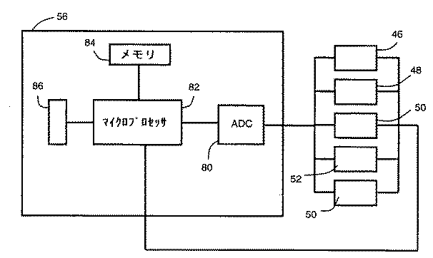
図3は個々のセンサ・アレー46、48、50、52、および、54に接続されるアナログ/デジタル変換機(ADC)80を含む信号プロセッサ56の概略図である。ADC80はメモリ84を有するマイクロプロセッサ82にも接続される。センサ・アレー46、48、50、52、および、54も温度計86のようにマイクロプロセッサ82に接続される。
FIG. 3 is a schematic diagram of a
続く図では、参照を容易にするために、図2に示す要素、コイン・チューブおよびセンサ・アレーを使用する。しかし、この図は、図1および図3に示す対応する構成要素のいずれにも等しく適用されることが理解されよう。 The following figures use the elements, coin tubes and sensor arrays shown in FIG. 2 for ease of reference. However, it will be understood that this figure applies equally to any of the corresponding components shown in FIGS.
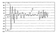
センサ・アレー72に接続されるマイクロプロセッサ82はスパーク・ギャップ74を放電させる。この放電は音響パルスを通路78の方向に走行させる。パルスは、積み重ねの最頂部のコインおよび他の表面に当ると、マイクロフォン76に向かって反射されて戻り、マイクロフォン76は反射されたパルスに応じて信号を発生する。マイクロフォン76によって発生された信号はADC80によってデジタルの形に変換され、ADCの出力は、メモリ84に保存される複数のデータ点を作成するために特定の間隔でマイクロプロセッサ82(図3)によってサンプリングされる。本実施形態において、この間隔は5.06μsである。
A
図4は上述の方法で導出されたデータ点90を示す。 FIG. 4 shows data points 90 derived in the manner described above.
図5〜7を参照して、第1の測定技術を説明する。
図5はデータ点90から導出された典型的なサンプル波形92を示す。サンプル波形92は、点90だけでなく、波形の解像度を高めるために使用される再構築アルゴリズムの使用によって再構築された追加の点にも基づく。保存されているデータおよびいかなる関連補間からも波形を導出する方法は信号再構築の技術分野ではよく知られていて、本明細書ではこれ以上は説明しない。
The first measurement technique will be described with reference to FIGS.
FIG. 5 shows a
コイン・チューブ70内のコインの積み重ねの高さを正確に決定するためには、波形92のどの部分が最頂部のコインからの音響パルスの反射に帰せられるのかを確認することが必要である。
To accurately determine the height of the stack of coins in the
事前の較正操作において、コイン・チューブ70に全くコインがなければ、スパーク・ギャップ74は点火され、参照波形100(図6)を形成するために再構築することができるデータ点が導出される。この参照波形に対応するデータ点はその後の読出しのためにメモリ84に保存される。この参照波形が空のチューブに対応するので、その後、測定操作において作成されるサンプル波形92との比較が、積み重ねの最頂部のコインからの音響パルスの反射に帰せられるサンプル波形の部分を強調する。
異なる寸法を持つと思われる他のチューブ70の較正も同様の方法で行われる。
In a pre-calibration operation, if there were no coins in the
Calibration of
図1〜3に示すタイプのコイン取り扱い装置は大量生産されている。もしそれらが十分に低い許容誤差レベルで生産されていれば、装置の較正の間にチューブのために導出されたデータ点は同じタイプの他の装置のために使用することができる。しかし、許容誤差が不十分に小さければ、較正は各装置について行わなければならない。コイン取り扱い装置が搬送され、使用される位置に設置されたなら、較正することがさらに必要となることがある。これは、搬送および設置の結果発生する機構の位置合わせの変化、および、湿度などの周囲の条件の相違からの測定への影響を回避する。 Coin handling devices of the type shown in FIGS. 1-3 are mass-produced. If they are produced with a sufficiently low tolerance level, the data points derived for the tubes during instrument calibration can be used for other instruments of the same type. However, if the tolerance is not sufficiently small, calibration must be performed for each device. Once the coin handling device has been transported and installed at the location where it will be used, further calibration may be required. This avoids changes in alignment of the mechanism that occur as a result of transport and installation, and the effects on measurements due to differences in ambient conditions such as humidity.
同じ番号が同じ要素を指定するために使用される図5、6、および、7を参照して、サンプル波形と参照波形との比較の処理を説明する。
サンプル波形および参照波形の双方の第1のプラス側ピーク94はコイン・チューブ70以外のコイン取り扱い装置10の部分に帰せられることが見出されている。したがって、(ピーク94の後にいずれの波形も最初に基線を横切る点である)参照点96の前に発生する全ての点は比較において無視される。
The process of comparing a sample waveform to a reference waveform will be described with reference to FIGS. 5, 6, and 7, where the same numbers are used to designate the same elements.
It has been found that the first
先ず、信頼できる比較が行えるようにサンプル波形の振幅は正規化される。サンプル波形の第1のマイナス側ピーク98が参照として取られ、このピーク98が参照波形100の第1のマイナス側ピーク102に等しくなるように、適切な係数がサンプル波形に適用される。
First, the amplitude of the sample waveform is normalized so that a reliable comparison can be made. The first
振幅の差を説明するためにサンプル波形が正規化されたならば、波形は温度変化を補償するためにさらに正規化されなければならない。音速はその音が伝播している媒体の温度変化に従って変化するので、参照波形100およびサンプル波形80が作成された時の周囲の温度の差はx軸(時間軸)に沿った波形のスケーリングとして現われる。これを補償するために、以下の式に従って、スケーリング係数がサンプル波形に適用される。
サンプル波形に対応する温度はマイクロプロセッサ82に付属する温度計86(図3)から確認される。
温度および振幅の差を補償するために波形が正規化されたならば、サンプル波形と参照波形との間の差は参照波形上の各点の値をサンプル波形上の対応する各点の値から減じることによって計算される。
The temperature corresponding to the sample waveform is ascertained from a thermometer 86 (FIG. 3) attached to
If the waveform was normalized to compensate for temperature and amplitude differences, the difference between the sample waveform and the reference waveform would be the value of each point on the reference waveform from the value of each corresponding point on the sample waveform. Calculated by subtracting.
温度差を補償するためにサンプル波形は説明した方法でスケーリングされたが、参照波形とサンプル波形との間のx軸に沿ったスケーリングのわずかな差でさえ、その差を計算する際には重大な誤差をもたらすことが見出されている。この誤差を最小に抑えるため、および、参照波形およびサンプル波形の対応する点が差の計算で使用されることを確実にするために、サンプル波形の各点はその点に時間的に最も近い参照波形の5つの点と比較される。続いて、参照波形の選択された点の値からサンプル波形の対応する点の値を減じることによって差の波形の各点を導出するために、差が最小になる参照波形の点が使用される。 Although the sample waveform was scaled in the manner described to compensate for the temperature difference, even small differences in scaling along the x-axis between the reference waveform and the sample waveform are significant in calculating the difference. Have been found to produce significant errors. To minimize this error, and to ensure that the corresponding points on the reference and sample waveforms are used in the difference calculation, each point on the sample waveform is the reference that is closest in time to that point. It is compared to five points on the waveform. Subsequently, the points of the reference waveform where the difference is minimal are used to derive each point of the difference waveform by subtracting the value of the corresponding point of the sample waveform from the value of the selected point of the reference waveform. .
図7は図5および図6の波形からこの方法で作成された差の波形110を示す。コインの積み重ねの高さを計算するために、参照波形110の最大マイナス側ピーク112が識別される。閾値114がピーク112の振幅の40%に設定され、差の波形が200μsに相当する距離にわたって矢印116の方向に走査される。閾値114を超える遭遇される第1のマイナス側ピークは、蓄積の最頂部のコインからの音響パルスの反射によって作成された波形の上述の部分と理解される。もしそのようなピークに遭遇しなければ、最大のマイナス側ピーク112が計算に使用される。しかし、上記に引用した数量、40%および200μsは述べた実施形態に特有のものであることが理解され、変化する条件に適合するために、これらの量は変化させることができることが推測されよう。
FIG. 7 shows a
続いて、積み重ねの高さを以下の式に従って計算することができる。
高さHは単一のコインを含むチューブに対するサンプル波形を作成することに関与する装置を使用して測定され、式(3)に従ってH’を計算すると以下のようになる。
H’が計算されたならば、Hは単一のコインの公知の厚さを減じることによってH’から導出される。
空のコイン・チューブはH’を計算するためには使用されない。なぜなら、チューブの底部の準開放的な性質が、結局は重大なエラーに翻訳され得るタイミング・エラーをもたらす位相変化を引き起こし得るからである。
Once H 'has been calculated, H is derived from H' by subtracting the known thickness of a single coin.
Empty coin tubes are not used to calculate H '. Because the quasi-open nature of the bottom of the tube can cause phase changes that result in timing errors that can eventually translate into significant errors.
比較的少ないコインを有するコインの積み重ねの高さを計算する時は、Hを計算するための差の波形としてサンプル波形が使用される。なぜなら、差の波形およびサンプル波形はこの二者の間で行われる信頼できる比較について類似し過ぎているからである。本実施形態においては、積み重ね内に5枚以下のコインがある時にこの技術が使用される。
コインの積み重ねの高さは、第2の測定技術によって決定することもできる。
When calculating the stack height of coins having relatively few coins, a sample waveform is used as the difference waveform for calculating H. This is because the difference waveform and the sample waveform are too similar for a reliable comparison made between the two. In this embodiment, this technique is used when there are five or fewer coins in the stack.
The height of the stack of coins can also be determined by a second measurement technique.
図5に示すタイプの第1のサンプル波形は上述の方法で作成される。1枚のコインが対応するコイン・チューブ70によって受領され、または、それから計量分配されたことをマイクロプロセッサが検出すると、同じく図5に示すタイプの第2のサンプル波形が際1のサンプル波形と同じ方法で作成される。
A first sample waveform of the type shown in FIG. 5 is created in the manner described above. When the microprocessor detects that a coin has been received or dispensed from the corresponding
続いて、低い方のコインの積み重ねに相当するサンプル波形が高い方のコインの積み重ねの高さに相当するサンプル波形から減じられる。したがって、第1の波形が第2の波形から減じられるのか、または、第2の波形から第1の波形から減じられるのかは計量配分動作が行われたのか、または、受領動作が行われたのかに依存する。 Subsequently, the sample waveform corresponding to the stack of lower coins is subtracted from the sample waveform corresponding to the stack height of the higher coins. Therefore, whether the first waveform is subtracted from the second waveform, or whether it is subtracted from the second waveform from the first waveform, is whether a metering operation has been performed or a receiving operation has been performed. Depends on.
結果として得られる差の波形は測定された2つのコイン蓄積の高い方に相当するピークを有する。この蓄積の高さは式(2)および(3)を参照して上述の方法で計算される。 The resulting difference waveform has a peak corresponding to the higher of the two measured coin accumulations. The height of this accumulation is calculated in the manner described above with reference to equations (2) and (3).
第2の技術において、振幅および/または軸の正規化は減算に先立っていずれか、または、双方の波形に適用することができる。しかし、好ましい実施形態においては時間軸の正規化(すなわち、温度補償)は行われない。もし第2の波形が導出される前に第1のサンプル波形の作成後に重大な時間の遅延があれば、第1の測定は破棄され、処理は再度開始される。このことは第1のサンプル波形と第2のサンプル波形との間に重大な温度差が存在しないことを、および、したがって、温度差を補償するためにいずれかの波形を正規化ことが不要であることを確実にする。しかし、両サンプル波形に温度補償が適用されていないので、これらの式におけるV(音速)は、積み重ねの高さを演繹する時に測定が行われる温度に従って調整される。この温度は温度計86から確かめられる。特定の温度におけるVに対する良好な近似は式(4)によって与えられる。
好ましい実施形態においては測定が正しいことを検証するために第1および第2の測定技術の双方が使用される。
したがって、第1および第2のサンプル波形は第1の測定技術を使用して各々解析され、個々のコイン蓄積の高さはそれらが単一のコインの分だけ異なることを検証するために比較される。続いて、第2の測定技術によって確かめられたコイン積み重ねの高さは、これが第1の技術を使用して導出された測定に合致することを調べるために検査される。したがって、現在の測定が正しいことを検証するために2つの検査がある。
In a preferred embodiment, both the first and second measurement techniques are used to verify that the measurement is correct.
Thus, the first and second sample waveforms are each analyzed using the first measurement technique, and the heights of the individual coin accumulations are compared to verify that they differ by a single coin. You. Subsequently, the height of the coin stack ascertained by the second measurement technique is checked to see if it matches the measurement derived using the first technique. Therefore, there are two tests to verify that the current measurement is correct.
いかなる数の測定も可能であるが、1回の測定を行うためにかかる時間がコインの積み重ねの高さの計算以外の多くの処理に関与するマイクロプロセッサ82の動作に干渉することがあるために、この時間がコイン蓄積の継続的な測定を非現実的にすることがある。したがって、コインの積み重ねの高さの測定は装置10のスイッチが入れられた時に行われ、処理は現在の測定が検証されるまで繰り返される。したがって、積み重ね内のコイン数の当座勘定は、測定から計算されたコイン数から受領および計量分配されたコイン数を減じる、または、追加することによって維持される。所望であれば、システムは、不正確な動作を防止するために、検証が達成されるまでは積み重ね内のコインの高さが個々の限界より上方および/または下方に進むことを防止するように構成することもできる。
Any number of measurements are possible, but because the time taken to make a single measurement can interfere with the operation of the
コインは厚さが変動し、それが、積み重ねの高さから積み重ね内のコインの枚数を決定する時のエラーをもたらす。このようなエラーは累積性を持ち、したがって、大きなコインの積み重ねでは特に顕著なことがある。この理由のために、もし当座勘定が、検証が再び達成されるまでに積み重ねが所定の閾値の下方に落ちたと決定すれば、積み重ねの測定はやり直される。本実施形態において、この閾値はコイン10枚である。 Coins vary in thickness, which leads to errors in determining the number of coins in a stack from the height of the stack. Such errors are cumulative and may therefore be particularly noticeable in large coin stacks. For this reason, if the current account determines that the stack has dropped below a predetermined threshold before verification is again achieved, the stack measurement is re-started. In the present embodiment, the threshold is 10 coins.
参照波形100はコイン・チューブ固有のものであることも見出されている。多くの参照波形を保存しておくことによって、マイクロプロセッサ82は異なったコイン・チューブを区別することができる。これは、図1の実施形態にあるように、額面金額または異なった通貨の異なった組み合わせを収容するために異なった各コイン・チューブをコイン確認機に取り付けることができるように確認機が構成されている時に特に有用である。
新しいコイン・チューブが確認機に取り付けられた時は、空のそのコイン・チューブに相当するサンプル波形が作成され、各々が異なったコイン・チューブに相当する複数の保存されている参照波形と比較される。サンプル波形は正規化され、温度差に対する補償が既に説明した方法で適用される。続いて、保存されている各参照波形からサンプル波形を減じること、および、参照波形が最小の差をもたらすことに注意することによって正しいコイン・チューブが識別される。 When a new coin tube is attached to the validator, a sample waveform corresponding to the empty coin tube is created and compared to multiple stored reference waveforms, each corresponding to a different coin tube. You. The sample waveform is normalized and compensation for temperature differences is applied in the manner already described. Subsequently, the correct coin tube is identified by subtracting the sample waveform from each stored reference waveform and noting that the reference waveform results in the least difference.
さらなる実施形態において、コイン・チューブはセットを形成し、コイン・チューブは1つのセットが他のセットに取って代わることによって交換される。続いて、特定のセットは、セットの各チューブに対する上記に概略を示した手順に従うことによって認識することができる。セット内の各チューブについてのサンプル波形は保存されている参照波形に対して比較される。個々のチューブについての結果を組み合わせることによって、セットを認識することができる。複数のセットのコイン・チューブを扱う時は、チューブのうちの1つの誤識別または無識別が、セット全体の結果が組み合わされた時に補償されることがある。 In a further embodiment, the coin tubes form a set, and the coin tubes are replaced by one set replacing another set. Subsequently, a particular set can be identified by following the procedure outlined above for each tube of the set. The sample waveform for each tube in the set is compared against a stored reference waveform. The set can be recognized by combining the results for the individual tubes. When dealing with multiple sets of coin tubes, misidentification or non-identification of one of the tubes may be compensated for when the results of the entire set are combined.
コイン・チューブおよびコイン・チューブのセットをこの方法で認識することは、(機械読取り可能な符合を認識するなどの)精緻な認識ルーチンでマイクロプロセッサをプログラムする必要性、または、コイン・チューブまたはコイン・チューブのセットが交換された時に関連設定を手動で変更することを回避する。 Recognizing a coin tube and a set of coin tubes in this way is necessary to program the microprocessor with sophisticated recognition routines (such as recognizing machine readable codes) or to use a coin tube or coin tube. -Avoid manually changing related settings when the set of tubes is replaced.
上記の構成において、サンプル波形の時間軸は参照波形の時間軸に整合させるために温度センサを使用して調整される。明らかに、参照波形の軸は代わりに、または、追加して調整できる。保存に先立って参照波形を正規化する代わりに、参照波形が作成された温度に基づいて、装置が特定の温度の制御可能な環境にある時に波形を作成することができる。さらなる選択肢は参照波形が作成される温度を保存することであり、そうすれば、(この温度とサンプル波形が導出される温度との差に基づく)単一の時間軸正規化手順だけが必要となる。 In the above configuration, the time axis of the sample waveform is adjusted using the temperature sensor to match the time axis of the reference waveform. Obviously, the axis of the reference waveform can be adjusted instead or additionally. Instead of normalizing the reference waveform prior to storage, the waveform can be created when the device is in a controllable environment at a particular temperature based on the temperature at which the reference waveform was created. A further option is to preserve the temperature at which the reference waveform is created, so that only a single time-base normalization procedure (based on the difference between this temperature and the temperature at which the sample waveform is derived) is needed. Become.
同様に、1組の波形の時間軸正規化のために温度センサを使用する代わりに、時間軸を整合させるために他の技術を使用することができる。例えば、波形を正規化するために、波形は特徴整合手順を使用して解析することができる。このような特徴整合は信号の解析および比較の技術分野ではよく知られており、本明細書ではさらなる説明はしない。代わりに、波形は時間軸の相対的スケーリングを決定するために相関させることができる。 Similarly, instead of using a temperature sensor for time axis normalization of a set of waveforms, other techniques can be used to align the time axis. For example, the waveform can be analyzed using a feature matching procedure to normalize the waveform. Such feature matching is well known in the art of signal analysis and comparison and will not be described further herein. Alternatively, the waveforms can be correlated to determine the relative scaling of the time axis.
振幅正規化は比較されている波形のいずれか、または、双方に適用することもでき、これらのうちの1つが参照波形である時、それは保存に先立って振幅正規化することができる。 Amplitude normalization can also be applied to either or both of the waveforms being compared, and when one of these is the reference waveform, it can be amplitude normalized prior to storage.
述べた方法および装置は、反射された圧力波が測定される位置ならどこでも応用例を見出すことができる。例えば、GB−A−2357617はコイン確認機の環境設定(例えば、コイン蓄積が存在するかどうか)を決定するため、コイン蓄積の寸法を検出するため、詰まったコインの存在を検出するため、または、自動販売機内の製品の数量を検出するために音響パルスの送信と反射との間の時間の測定の使用を開示している。本方法および装置は、これらの測定のいずれでも、より高い精度を達成するために使用することができる。 The described method and apparatus can find application anywhere where the reflected pressure wave is measured. For example, GB-A-2357617 determines the configuration of a coin validator (e.g., whether there is coin accumulation), detects the size of coin accumulation, detects the presence of jammed coins, or Discloses the use of measuring the time between the transmission and reflection of an acoustic pulse to detect the quantity of a product in a vending machine. The method and apparatus can be used to achieve higher accuracy with any of these measurements.
Claims (21)
Applications Claiming Priority (1)
| Application Number | Priority Date | Filing Date | Title |
|---|---|---|---|
| EP02257410A EP1413991B1 (en) | 2002-10-24 | 2002-10-24 | Coin store measurement |
Publications (3)
| Publication Number | Publication Date |
|---|---|
| JP2004164631A true JP2004164631A (en) | 2004-06-10 |
| JP2004164631A5 JP2004164631A5 (en) | 2006-12-07 |
| JP4286107B2 JP4286107B2 (en) | 2009-06-24 |
Family
ID=32050101
Family Applications (1)
| Application Number | Title | Priority Date | Filing Date |
|---|---|---|---|
| JP2003364608A Expired - Fee Related JP4286107B2 (en) | 2002-10-24 | 2003-10-24 | Coin accumulation measurement |
Country Status (6)
| Country | Link |
|---|---|
| US (1) | US7195113B2 (en) |
| EP (1) | EP1413991B1 (en) |
| JP (1) | JP4286107B2 (en) |
| CN (1) | CN100523866C (en) |
| DE (1) | DE60218856T2 (en) |
| ES (1) | ES2280489T3 (en) |
Cited By (1)
| Publication number | Priority date | Publication date | Assignee | Title |
|---|---|---|---|---|
| CN104303213A (en) * | 2012-05-08 | 2015-01-21 | 梅伊有限公司 | Acoustic coin sensor |
Families Citing this family (16)
| Publication number | Priority date | Publication date | Assignee | Title |
|---|---|---|---|---|
| GB2357617A (en) * | 1999-12-23 | 2001-06-27 | Mars Inc | Methods for detecting surfaces in vending machines |
| AU2003215283B2 (en) | 2002-02-15 | 2007-05-24 | Coinstar, Llc | Apparatuses and methods for dispensing cards |
| DE60218856T2 (en) | 2002-10-24 | 2008-01-17 | Mei, Inc. | Münzspeichermessung |
| US20060065265A1 (en) * | 2004-09-27 | 2006-03-30 | Bsh Home Appliances Corporation | Extendable oven rack assembly |
| US20070072534A1 (en) * | 2005-09-26 | 2007-03-29 | Coin Acceptors, Inc. | Tube status sensing method and control field of the invention |
| US9233812B2 (en) * | 2005-12-05 | 2016-01-12 | Outerwall Inc. | Card dispensing apparatuses and associated methods of operation |
| DE102006037947B3 (en) * | 2006-08-12 | 2007-12-13 | National Rejectors, Inc. Gmbh | Coin collection device for vending machines, has coin collecting tube with base supporting coin pile at lower end attached within framework, where power operated pusher is assigned to lower end for pushing out lowest coin in outlet channel |
| ITMI20070930A1 (en) * | 2007-05-08 | 2008-11-09 | Vesiel S P A | COIN COUNTING DEVICE PARTICULARLY FOR METAL METAL INLET AND INPUT SYSTEMS. |
| DE202009007155U1 (en) | 2009-05-18 | 2009-10-15 | Mei, Inc. | Geldspeicher evaluation |
| US9227800B2 (en) | 2013-03-14 | 2016-01-05 | Outerwall Inc. | Multi-function card handling apparatus and methods of operation |
| DE202015101489U1 (en) * | 2015-03-24 | 2016-06-28 | Crane Payment Innovations Gmbh | Device for determining the level of coin tubes |
| DE102015105286B4 (en) * | 2015-04-08 | 2017-07-06 | Crane Payment Innovations Gmbh | Method and device for determining the level of coin tubes |
| ITUB20160080A1 (en) * | 2016-01-28 | 2017-07-28 | Coges S P A | A COIN CONTAINER DEVICE |
| CN107123189A (en) * | 2017-06-06 | 2017-09-01 | 南京宝坚电子科技有限公司 | A kind of sound wave antarafacial surveys counting apparatus and the survey counting method based on the device |
| CN107346572B (en) * | 2017-06-06 | 2023-03-24 | 南京宝坚电子科技有限公司 | Intelligent coin identification change-giving device |
| US11197962B2 (en) * | 2018-02-26 | 2021-12-14 | Verily Life Sciences Llc | Waveform reconstruction for ultrasound time of flight measurements |
Family Cites Families (22)
| Publication number | Priority date | Publication date | Assignee | Title |
|---|---|---|---|---|
| US3901367A (en) | 1973-04-11 | 1975-08-26 | Mitani Shoji Co Ltd | Coin testing apparatus |
| US4012588A (en) | 1975-08-29 | 1977-03-15 | Science Accessories Corporation | Position determining apparatus and transducer therefor |
| US4223790A (en) | 1978-02-13 | 1980-09-23 | Hajime Industries, Ltd. | Container inspection system |
| US4345650A (en) | 1980-04-11 | 1982-08-24 | Wesley Richard H | Process and apparatus for electrohydraulic recovery of crude oil |
| GB2139352A (en) | 1983-05-04 | 1984-11-07 | Central Electr Generat Board | Fluid temperature and velocity measuring arrangement |
| US4590975A (en) | 1984-06-13 | 1986-05-27 | The Coca-Cola Company | Automatic beverage dispensing system |
| CA1214858A (en) * | 1984-09-27 | 1986-12-02 | Stanley Panton | Acoustic ranging system |
| GB8612479D0 (en) * | 1986-05-22 | 1986-07-02 | Bell Fruit Mfg Co Ltd | Coin handling equipment |
| US5092816A (en) | 1990-09-25 | 1992-03-03 | Coin Acceptors, Inc. | Coin tube monitor and control means |
| FR2706057B1 (en) | 1993-06-02 | 1995-08-11 | Schlumberger Ind Sa | Device for sorting and storing objects introduced as payment in a dispenser. |
| US5505090A (en) | 1993-11-24 | 1996-04-09 | Holographics Inc. | Method and apparatus for non-destructive inspection of composite materials and semi-monocoque structures |
| US5929337A (en) | 1994-11-11 | 1999-07-27 | M & A Packaging Services Limited | Non-mechanical contact ultrasound system for monitoring contents of a moving container |
| US5755618A (en) | 1995-09-14 | 1998-05-26 | Grips Electronic Gmbh | Apparatus for storing coins or coin-like articles |
| US5821424A (en) * | 1995-10-16 | 1998-10-13 | Lockheed Idaho Technologies Company | Method and apparatus for analyzing the fill characteristics of a packaging container |
| GB9522949D0 (en) | 1995-11-09 | 1996-01-10 | M & A Packaging Serv Ltd | Fill level measuring |
| US5708223A (en) | 1996-01-25 | 1998-01-13 | Leer Manufacturing Limited Partnership | Remote sensing ice merchandiser |
| US5742656A (en) * | 1996-03-21 | 1998-04-21 | The Casino Software Corporation Of America | Gaming token tray employing ultrasonic token counting |
| DE19727960C2 (en) | 1997-07-01 | 1999-10-14 | Peus Systems Gmbh | Device for the temporally high-resolution measurement of a gaseous volume flow, in particular an exhaust gas volume flow of an internal combustion engine, in a pipe through which it flows |
| WO2000065546A1 (en) | 1999-04-28 | 2000-11-02 | Cummins-Allison Corp. | Currency processing machine with multiple coin receptacles |
| GB2357617A (en) | 1999-12-23 | 2001-06-27 | Mars Inc | Methods for detecting surfaces in vending machines |
| JP3558974B2 (en) * | 2000-08-30 | 2004-08-25 | ローレル精機株式会社 | Coin wrapping machine |
| DE60218856T2 (en) | 2002-10-24 | 2008-01-17 | Mei, Inc. | Münzspeichermessung |
-
2002
- 2002-10-24 DE DE60218856T patent/DE60218856T2/en not_active Expired - Lifetime
- 2002-10-24 EP EP02257410A patent/EP1413991B1/en not_active Expired - Lifetime
- 2002-10-24 ES ES02257410T patent/ES2280489T3/en not_active Expired - Lifetime
-
2003
- 2003-10-22 US US10/690,765 patent/US7195113B2/en active Active
- 2003-10-24 CN CNB2003101203310A patent/CN100523866C/en not_active Expired - Fee Related
- 2003-10-24 JP JP2003364608A patent/JP4286107B2/en not_active Expired - Fee Related
Cited By (2)
| Publication number | Priority date | Publication date | Assignee | Title |
|---|---|---|---|---|
| CN104303213A (en) * | 2012-05-08 | 2015-01-21 | 梅伊有限公司 | Acoustic coin sensor |
| CN104303213B (en) * | 2012-05-08 | 2018-11-13 | 梅伊有限公司 | Sound coin sensor |
Also Published As
| Publication number | Publication date |
|---|---|
| CN100523866C (en) | 2009-08-05 |
| EP1413991B1 (en) | 2007-03-14 |
| EP1413991A1 (en) | 2004-04-28 |
| ES2280489T3 (en) | 2007-09-16 |
| DE60218856D1 (en) | 2007-04-26 |
| JP4286107B2 (en) | 2009-06-24 |
| US7195113B2 (en) | 2007-03-27 |
| CN1501094A (en) | 2004-06-02 |
| DE60218856T2 (en) | 2008-01-17 |
| US20040079615A1 (en) | 2004-04-29 |
Similar Documents
| Publication | Publication Date | Title |
|---|---|---|
| JP4286107B2 (en) | Coin accumulation measurement | |
| EP0058094B1 (en) | Improvements in and relating to apparatus for checking the validity of coins | |
| EP0043189B1 (en) | Method of and apparatus for assessing coins | |
| KR920704243A (en) | Method and apparatus for accepting coins, bills and other currencies and rejecting fake coins or counterfeit bills | |
| JP4126668B2 (en) | Coin checker | |
| JP2004164631A5 (en) | ||
| US20030183012A1 (en) | Verification of thickness modulations in or on sheet-type products | |
| JP2003263668A (en) | Calibration of currency validator | |
| US7699689B2 (en) | Vending machines and coin handling apparatus | |
| EP0700552B1 (en) | Coin validation | |
| EP2847742A1 (en) | Acoustic coin sensor | |
| JPH04507020A (en) | coin checker | |
| RU2155381C2 (en) | Device for checking authenticity of coins, tokens and other flat metal objects | |
| US20070072534A1 (en) | Tube status sensing method and control field of the invention | |
| EP2230645B1 (en) | Device and method for detecting the amount of coins in a tank | |
| JPH08305922A (en) | Method and device for inspecting paper sheets | |
| JP4379238B2 (en) | Coin identification device | |
| JPS6222194A (en) | Coin discrimination system | |
| JP3350958B2 (en) | Coin identification device | |
| CA2163869C (en) | Coin validation | |
| JPH1153604A (en) | Correction method for optical sensor output | |
| JPS5860389A (en) | Discrimination of coin | |
| KR870009309A (en) | Currency Confirmation Method and Device | |
| JPS5931754B2 (en) | coin sorting device | |
| JPS5931753B2 (en) | coin sorting device |
Legal Events
| Date | Code | Title | Description |
|---|---|---|---|
| A711 | Notification of change in applicant |
Free format text: JAPANESE INTERMEDIATE CODE: A711 Effective date: 20060823 |
|
| A521 | Request for written amendment filed |
Free format text: JAPANESE INTERMEDIATE CODE: A523 Effective date: 20061024 |
|
| A621 | Written request for application examination |
Free format text: JAPANESE INTERMEDIATE CODE: A621 Effective date: 20061024 |
|
| A977 | Report on retrieval |
Free format text: JAPANESE INTERMEDIATE CODE: A971007 Effective date: 20071005 |
|
| A131 | Notification of reasons for refusal |
Free format text: JAPANESE INTERMEDIATE CODE: A131 Effective date: 20071015 |
|
| A601 | Written request for extension of time |
Free format text: JAPANESE INTERMEDIATE CODE: A601 Effective date: 20080115 |
|
| A602 | Written permission of extension of time |
Free format text: JAPANESE INTERMEDIATE CODE: A602 Effective date: 20080118 |
|
| A521 | Request for written amendment filed |
Free format text: JAPANESE INTERMEDIATE CODE: A523 Effective date: 20080415 |
|
| TRDD | Decision of grant or rejection written | ||
| A01 | Written decision to grant a patent or to grant a registration (utility model) |
Free format text: JAPANESE INTERMEDIATE CODE: A01 Effective date: 20090309 |
|
| A01 | Written decision to grant a patent or to grant a registration (utility model) |
Free format text: JAPANESE INTERMEDIATE CODE: A01 |
|
| A61 | First payment of annual fees (during grant procedure) |
Free format text: JAPANESE INTERMEDIATE CODE: A61 Effective date: 20090324 |
|
| FPAY | Renewal fee payment (event date is renewal date of database) |
Free format text: PAYMENT UNTIL: 20120403 Year of fee payment: 3 |
|
| R150 | Certificate of patent or registration of utility model |
Free format text: JAPANESE INTERMEDIATE CODE: R150 |
|
| FPAY | Renewal fee payment (event date is renewal date of database) |
Free format text: PAYMENT UNTIL: 20120403 Year of fee payment: 3 |
|
| FPAY | Renewal fee payment (event date is renewal date of database) |
Free format text: PAYMENT UNTIL: 20130403 Year of fee payment: 4 |
|
| FPAY | Renewal fee payment (event date is renewal date of database) |
Free format text: PAYMENT UNTIL: 20130403 Year of fee payment: 4 |
|
| FPAY | Renewal fee payment (event date is renewal date of database) |
Free format text: PAYMENT UNTIL: 20140403 Year of fee payment: 5 |
|
| R250 | Receipt of annual fees |
Free format text: JAPANESE INTERMEDIATE CODE: R250 |
|
| LAPS | Cancellation because of no payment of annual fees |