JP2004155222A - Tire state monitoring device - Google Patents
Tire state monitoring device Download PDFInfo
- Publication number
- JP2004155222A JP2004155222A JP2002320207A JP2002320207A JP2004155222A JP 2004155222 A JP2004155222 A JP 2004155222A JP 2002320207 A JP2002320207 A JP 2002320207A JP 2002320207 A JP2002320207 A JP 2002320207A JP 2004155222 A JP2004155222 A JP 2004155222A
- Authority
- JP
- Japan
- Prior art keywords
- tire
- transmitter
- vehicle
- data
- monitoring device
- Prior art date
- Legal status (The legal status is an assumption and is not a legal conclusion. Google has not performed a legal analysis and makes no representation as to the accuracy of the status listed.)
- Pending
Links
- 238000012806 monitoring device Methods 0.000 title claims abstract description 25
- 230000001133 acceleration Effects 0.000 claims abstract description 44
- 230000004044 response Effects 0.000 claims abstract description 27
- 238000001514 detection method Methods 0.000 claims description 10
- 238000012544 monitoring process Methods 0.000 claims description 10
- 230000005540 biological transmission Effects 0.000 description 48
- 230000000694 effects Effects 0.000 description 6
- 238000005259 measurement Methods 0.000 description 5
- 238000010586 diagram Methods 0.000 description 4
- 230000005684 electric field Effects 0.000 description 4
- 230000002159 abnormal effect Effects 0.000 description 3
- 230000006870 function Effects 0.000 description 3
- 238000000034 method Methods 0.000 description 3
- 230000005856 abnormality Effects 0.000 description 2
- 230000002238 attenuated effect Effects 0.000 description 2
- 238000012545 processing Methods 0.000 description 2
- 238000002474 experimental method Methods 0.000 description 1
- 230000010354 integration Effects 0.000 description 1
- 230000000737 periodic effect Effects 0.000 description 1
- 230000035945 sensitivity Effects 0.000 description 1
Images


Classifications
-
- B—PERFORMING OPERATIONS; TRANSPORTING
- B60—VEHICLES IN GENERAL
- B60C—VEHICLE TYRES; TYRE INFLATION; TYRE CHANGING; CONNECTING VALVES TO INFLATABLE ELASTIC BODIES IN GENERAL; DEVICES OR ARRANGEMENTS RELATED TO TYRES
- B60C23/00—Devices for measuring, signalling, controlling, or distributing tyre pressure or temperature, specially adapted for mounting on vehicles; Arrangement of tyre inflating devices on vehicles, e.g. of pumps or of tanks; Tyre cooling arrangements
- B60C23/02—Signalling devices actuated by tyre pressure
- B60C23/04—Signalling devices actuated by tyre pressure mounted on the wheel or tyre
- B60C23/0408—Signalling devices actuated by tyre pressure mounted on the wheel or tyre transmitting the signals by non-mechanical means from the wheel or tyre to a vehicle body mounted receiver
- B60C23/0415—Automatically identifying wheel mounted units, e.g. after replacement or exchange of wheels
- B60C23/0416—Automatically identifying wheel mounted units, e.g. after replacement or exchange of wheels allocating a corresponding wheel position on vehicle, e.g. front/left or rear/right
-
- B—PERFORMING OPERATIONS; TRANSPORTING
- B60—VEHICLES IN GENERAL
- B60C—VEHICLE TYRES; TYRE INFLATION; TYRE CHANGING; CONNECTING VALVES TO INFLATABLE ELASTIC BODIES IN GENERAL; DEVICES OR ARRANGEMENTS RELATED TO TYRES
- B60C23/00—Devices for measuring, signalling, controlling, or distributing tyre pressure or temperature, specially adapted for mounting on vehicles; Arrangement of tyre inflating devices on vehicles, e.g. of pumps or of tanks; Tyre cooling arrangements
- B60C23/02—Signalling devices actuated by tyre pressure
- B60C23/04—Signalling devices actuated by tyre pressure mounted on the wheel or tyre
- B60C23/0408—Signalling devices actuated by tyre pressure mounted on the wheel or tyre transmitting the signals by non-mechanical means from the wheel or tyre to a vehicle body mounted receiver
- B60C23/0422—Signalling devices actuated by tyre pressure mounted on the wheel or tyre transmitting the signals by non-mechanical means from the wheel or tyre to a vehicle body mounted receiver characterised by the type of signal transmission means
- B60C23/0433—Radio signals
- B60C23/0447—Wheel or tyre mounted circuits
- B60C23/0455—Transmission control of wireless signals
- B60C23/0462—Structure of transmission protocol
-
- B—PERFORMING OPERATIONS; TRANSPORTING
- B60—VEHICLES IN GENERAL
- B60C—VEHICLE TYRES; TYRE INFLATION; TYRE CHANGING; CONNECTING VALVES TO INFLATABLE ELASTIC BODIES IN GENERAL; DEVICES OR ARRANGEMENTS RELATED TO TYRES
- B60C23/00—Devices for measuring, signalling, controlling, or distributing tyre pressure or temperature, specially adapted for mounting on vehicles; Arrangement of tyre inflating devices on vehicles, e.g. of pumps or of tanks; Tyre cooling arrangements
- B60C23/02—Signalling devices actuated by tyre pressure
- B60C23/04—Signalling devices actuated by tyre pressure mounted on the wheel or tyre
- B60C23/0408—Signalling devices actuated by tyre pressure mounted on the wheel or tyre transmitting the signals by non-mechanical means from the wheel or tyre to a vehicle body mounted receiver
- B60C23/0483—Wireless routers between wheel mounted transmitters and chassis mounted receivers
-
- B—PERFORMING OPERATIONS; TRANSPORTING
- B60—VEHICLES IN GENERAL
- B60C—VEHICLE TYRES; TYRE INFLATION; TYRE CHANGING; CONNECTING VALVES TO INFLATABLE ELASTIC BODIES IN GENERAL; DEVICES OR ARRANGEMENTS RELATED TO TYRES
- B60C23/00—Devices for measuring, signalling, controlling, or distributing tyre pressure or temperature, specially adapted for mounting on vehicles; Arrangement of tyre inflating devices on vehicles, e.g. of pumps or of tanks; Tyre cooling arrangements
- B60C23/02—Signalling devices actuated by tyre pressure
- B60C23/04—Signalling devices actuated by tyre pressure mounted on the wheel or tyre
- B60C23/0486—Signalling devices actuated by tyre pressure mounted on the wheel or tyre comprising additional sensors in the wheel or tyre mounted monitoring device, e.g. movement sensors, microphones or earth magnetic field sensors
- B60C23/0488—Movement sensor, e.g. for sensing angular speed, acceleration or centripetal force
Landscapes
- Engineering & Computer Science (AREA)
- Mechanical Engineering (AREA)
- Computer Networks & Wireless Communication (AREA)
- Measuring Fluid Pressure (AREA)
- Arrangements For Transmission Of Measured Signals (AREA)
Abstract
Description
【0001】
【発明の属する技術分野】
本発明は、タイヤ状態監視装置に関し、より詳しくはタイヤ空気圧等のタイヤ状態を車室内から確認できる無線方式のタイヤ状態監視装置に関するものである。
【0002】
【従来の技術】
従来より、車両に装着されたタイヤの状態を車室内で確認するために、無線方式のタイヤ状態監視装置が用いられている。各タイヤのホイールには、対応するタイヤの空気圧や温度等の状態を計測して、計測されたタイヤ状態を示すデータを無線送信するための送信機が装着される。車両の車体には、送信機からのデータを受け取るための受信機が設けられる。
【0003】
送信機は、車両に装着された複数のタイヤの各々に設けられる。受信機は、送信機にそれぞれ対応する複数の受信アンテナを備える。各受信アンテナは、送信機から発信される電波の電界強度に応じた電圧を誘起する。受信機は、受信アンテナで誘起された電圧信号から必要なデータを取り出すべく、その電圧信号を処理する。
【0004】
ところで、受信機は、受信されたデータが何れのタイヤに設けられた送信機から無線送信されたものであるのかを特定する必要がある。そこで、タイヤ状態監視装置の受信機では、誘起電圧レベルの最も大きい受信アンテナを特定すべく、同時期に1つの受信アンテナのみが有効化されるように、複数の受信アンテナがマルチプレクサ回路によって切り換えられる。そして、電圧信号のレベルが最も高くなったときに有効化された受信アンテナが、発信元の送信機に最も近い受信アンテナであると判定される。従って、タイヤの取付位置を特定できる(特許文献1参照)。
【0005】
【特許文献1】
特開平10−104103号公報(第6−9頁、図1)
【0006】
【発明が解決しようとする課題】
しかしながら、特許文献1の構成では、タイヤの本数に応じた受信アンテナが必須要件である。また、受信アンテナは、誘起電圧レベルが大きくなるように、車体のタイヤの近傍に設ける必要があり、その取り付け方法にも制限があった。
【0007】
加えて、送信機からの信号の受信を待つ間中、マルチプレクサ回路を能動状態に維持して、全ての受信アンテナからの電圧信号を受け取ることができるようにしておく必要がある。そのため、電力消費量が多くなる。
【0008】
さらに、送信機の特定処理に際して、同時期に1つの受信アンテナのみが有効化されるので、得られる電圧信号のレベルが比較的低くなる。そのため、送信機の特定処理を正確且つ確実に実行することが難しい。
【0009】
本発明は、このような問題点に着目してなされたものであって、その目的は、タイヤの取付位置を特定することが可能なタイヤ状態監視装置を提供することにある。
【0010】
【課題を解決するための手段】
上記の目的を達成するために、請求項1に記載の発明では、車両に設けられた複数のタイヤの状態を監視するためのタイヤ状態監視装置であって、車両の前部に設けられた左右の前輪タイヤと、車両の後部に設けられた左右の後輪タイヤとを含むタイヤと、各タイヤに設けられた送信機であって、対応するタイヤの状態を検出する状態検出手段と、対応するタイヤの回転に伴う加速度の方向を検出する加速度検出手段とを備え、状態検出手段で検出したタイヤの状態を示すデータ及び加速度検出手段で検出した加速度の方向を示すデータを含むデータを無線送信する送信機と、前輪タイヤに設けられた送信機からのデータ、又は後輪タイヤに設けられた送信機からのデータを受信するリピータであって、送信機からのデータを受信した場合には、所定時間経過後に応答信号を無線送信するリピータと、各送信機からのデータ及びリピータからの応答信号を受信する受信機であって、送信機の1つからデータを受信した後にリピータからの応答信号を受信したか否かに基づいて、発信元の送信機が設けられたタイヤの取付位置を特定する受信機とを備えた。
【0011】
請求項2に記載の発明では、請求項1に記載のタイヤ状態監視装置において、受信機は、車両の速度と車両の進行方向とに基づいて、タイヤの回転方向を把握する。
【0012】
請求項3に記載の発明では、請求項1または請求項2に記載のタイヤ状態監視装置において、受信機は、送信機の1つからデータを受信した後にリピータからの応答信号を受信したか否かに基づいて、その送信機が設けられたタイヤの取付位置の情報を記憶する。
【0013】
請求項4に記載の発明では、請求項1〜請求項3のいずれか1項に記載のタイヤ状態監視装置において、リピータをタイヤの近傍における車両の部分に設けた。
【0014】
【発明の実施の形態】
以下に、本発明に係るタイヤ状態監視装置を自動車等の車両に具体化した一実施形態について図面を用いて説明する。
【0015】
図1に示すように、タイヤ状態監視装置1は、車両10の4つのタイヤ20に設けられた4つの送信機30と、車両10の車体11に設けられた1つの受信機40とを備えている。
【0016】
車両10は、その前部に設けられた左右の前輪(FL,FR)のタイヤ20、及びその後部に設けられた左右の後輪(RL,RR)のタイヤ20を備えている。
【0017】
各送信機30は、それぞれ対応するタイヤ20の内部、例えばタイヤ20のホイール21に固定されている。そして、各送信機30は、対応するタイヤ20の状態、すなわち対応するタイヤ20内の空気圧及び温度を計測して、その計測によって得られたタイヤ20の空気圧データ及び温度データを含むデータを無線送信する。
【0018】
受信機40は、車体11の所定箇所に設置され、例えば車両10のバッテリ(図示略)からの電力によって動作する。受信機40は、1つの受信アンテナ41を備えている。受信アンテナ41は、ケーブル42を介して受信機40に接続されている。受信機40は、各送信機30から無線送信されたデータを受信アンテナ41を介して受信する。
【0019】
リピータ51,52は、それぞれ後輪左側(RL)、後輪右側(RR)のタイヤ20の近傍における車体11、例えば後輪左側(RL)、後輪右側(RR)のタイヤ20のタイヤハウス内に配設されている。
【0020】
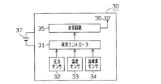
図2に示すように、各送信機30は、マイクロコンピュータ等よりなる送信コントローラ31を備える。送信コントローラ31は、例えば、中央処理装置(CPU)、リードオンリメモリ(ROM)及びランダムアクセスメモリ(RAM)を備えている。送信コントローラ31の内部メモリ、例えばROMには、予め固有のIDコードが登録されている。そして、このIDコードは、4つのタイヤ20に設けられた4つの送信機30を識別するために利用されている。
【0021】
圧力センサ32は、タイヤ20内の空気圧を計測して、その計測によって得られた空気圧データを送信コントローラ31に出力する。温度センサ33は、タイヤ20内の温度を計測して、その計測によって得られた温度データを送信コントローラ31に出力する。圧力センサ32及び温度センサ33は、状態検出手段として機能する。
【0022】
送信コントローラ31は、入力された空気圧データ及び温度データ並びに自身に登録されているIDコードを送信回路35に出力する。
送信回路35は、送信コントローラ31から出力されてきたデータを符号化及び変調した後、そのデータを送信アンテナ36を介して無線送信する。
【0023】
送信機30は、電池37を備えている。送信機30は、その電池37からの電力によって動作する。
送信コントローラ31は、予め定められた時間間隔(例えば15秒間隔)毎に、圧力センサ32及び温度センサ33に計測動作を行わせる。また、送信コントローラ31は、圧力センサ32の計測回数が所定値(例えば40回)に達する毎に、送信回路35に定期的な送信動作を行わせる。さらに、送信コントローラ31は、対応するタイヤ20内の空気圧の異常或いはタイヤ20内の温度の異常を認識した場合には、定期的な送信とは関係なく、送信回路35に送信動作を行わせる。
【0024】
なお、各送信機30が他の送信機30と異なるタイミングで定期送信を実行するように、各送信機30の送信タイミングが調整されている。従って、各送信機30のうちの2つ以上が同時に送信を行うことはない。
【0025】
図3(a)に示すように、加速度検出手段としての加速度センサ34は、タイヤ20の回転方向に基づく、加速度の方向を示すデータ(加速度データ)を送信コントローラ31に出力する。
【0026】
具体的には、例えば前輪左側(FL)のタイヤ20は、車両10の前進時には「+G」の加速度データを、車両10の後進時には「−G」の加速度データを、それぞれ送信コントローラ31に出力する。一方、前輪右側(FR)のタイヤ20は、前輪左側(FL)のタイヤ20とは、逆方向に回転するため、車両10の前進時には「−G」の加速度データを、車両10の後進時には「+G」の加速度データを、それぞれ送信コントローラ31に出力する。なお、後輪左側(RL)、後輪右側(RR)のタイヤ20についても同様である。従って、受信機40は、各送信機30からのデータを受信したとき、加速度センサ34からの加速度データに基づいて、前後輪左側(FL,RL)のタイヤ20か、或いは前後輪右側(FR,RR)のタイヤ20かを特定することができる。
【0027】
送信コントローラ31は、加速度センサ34からの加速度データを送信回路35に出力する。そして、送信コントローラ31は、入力された加速度データを送信回路35に出力する。送信回路35は、送信コントローラ31から出力されてきた加速度データを符号化及び変調した後、そのデータを送信アンテナ36を介して無線送信する。すなわち、送信回路35は、前述した空気圧データ、温度データ並びに自身に登録されているIDコードとともに、加速度データを符号化及び変調した後、そのデータを送信アンテナ36を介して無線送信する。
【0028】
次に、リピータ51,52について図4を用いて説明する。
図4に示すように、リピータ51,52は、送信機30から無線送信されたデータを受信すると、予め設定された所定時間T1が経過した後に、応答信号T2を無線送信する。ここで、リピータ51,52から発信される電波の周波数は、各送信機30から発信される電波の周波数と同一である。従って、リピータ51,52及び各送信機30から発信される電波も、同一の受信機40で受信することができる。
【0029】
ところで、送信機30から発信された電波が伝わるときには、その電界強度は距離に比例して減衰する。図1に示すように、各タイヤ20に設けられた送信機30から発信される電波の電界強度は同じである。しかし、後輪左側(RL)のタイヤハウス内に配設されたリピータ51には、後輪左側(RL)のタイヤ20に設けられた送信機30からの電波が、他の送信機30からの電波よりも、強く受信される。
【0030】
実験によれば、送信機30の送信出力が3〔m〕の遠点で、50〔dBμV/m〕の電界強度であれば、−90〔dBm〕の受信感度のリピータ51を後輪左側(RL)のタイヤハウス内に配設すれば、後輪左側(RL)のタイヤ20に設けられた送信機30からの電波のみを受信できることが確認されている。換言すれば、前輪左側(FL)、前輪右側(FR)、後輪右側(RR)のタイヤ20に設けられた送信機30からの電波は減衰されて、リピータ51で殆ど受信されないことが確認されている。また、リピータ52についても同様に、前輪左側(FL)、前輪右側(FR)、後輪左側(RL)のタイヤ20に設けられた送信機30からの電波は減衰されて、リピータ52で殆ど受信されないことが確認されている。
【0031】
従って、送信機30から無線送信されたデータが受信機40で受信された後、所定時間T1が経過した後に、この応答信号T2が受信機40で受信されれば、後輪(RL,RR)のタイヤ20であることを特定することができる。一方、送信機30から無線送信されたデータが受信機40で受信された後、所定時間T1が経過した後に、この応答信号T2が受信機40で受信されなければ、前輪(FL,FR)のタイヤ20であることを特定することができる。
【0032】
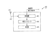
次に、受信機40について図5を用いて説明する。
図5に示すように、受信機40は、受信アンテナ41を介して受信されたデータを処理するための受信コントローラ44、受信回路45及び表示器46を備えている。マイクロコンピュータ等よりなる受信コントローラ44は、例えばCPU、ROM及びRAMを備えている。
【0033】
受信回路45は、各送信機30から無線送信されたデータ及びリピータ51,52から無線送信された応答信号を受信アンテナ41を介して受信する。また、受信回路45は、受信されたデータ及び応答信号を復調及び復号した後、受信コントローラ44に送出する。
【0034】
受信コントローラ44は、前述した加速度センサ34からの加速度データ、及び前述したリピータ51,52からの応答信号T2の有無に基づいて、4つのタイヤ20のうちのいずれのタイヤ20であるかを認識する。
【0035】
受信コントローラ44は、車両10の速度を示す信号(車速信号)を、車両10に設けられた所定の装置、例えばスピードメータ(図示略)から受け取る。また、受信コントローラ44は、車両10の進行方向を示す信号(進行方向信号)を、車両10に設けられた所定の装置、例えば変速機(図示略)から受け取る。変速機は、シフトレバーのシフト位置を示す信号を、進行方向信号として、受信コントローラ44に出力する。受信コントローラ44は、入力された進行方向信号に基づき、車両10が前進中であるか後進中であるかを判定する。なお、シフトレバーのシフト位置が後進位置にある場合のみ、受信コントローラ44は車両10が後進中であると判定する。シフト位置が後進位置以外の位置にある場合には、受信コントローラ44は車両10が前進中であるとみなす。
【0036】
その結果、受信コントローラ44は、車速信号と進行方向信号とに基づいて、車両10の走行中でも、タイヤ20の回転方向を把握することができる。従って、受信機40は、加速度センサ34からの加速度データと、車速信号と、進行方向信号とに基づいて、より一層正確に前後輪左側(FL,RL)のタイヤ20か、或いは前後輪右側(FR,RR)のタイヤ20かを特定することができる。
【0037】
受信コントローラ44は、発信元の送信機30に対応するタイヤ20の取付位置の情報を、例えばRAMに記憶する。具体的には、発信元の送信機30に対応するタイヤ20の取付位置の情報と、受信されたデータに含まれるIDコードとを関連付けて記憶する。
【0038】
また、受信コントローラ44は、受信されたデータ及び応答信号に基づいて、発信元の送信機30に対応するタイヤ20の空気圧及び温度を把握する。さらに、受信コントローラ44は、発信元の送信機30に対応するタイヤ20の空気圧及び温度に関するデータと、それらのデータに対応するタイヤ20の取付位置の情報とを表示器46に表示させる。特に、タイヤ20の空気圧が異常である場合には、その旨を表示器46に警告表示する。表示器46は、報知手段として機能する。
【0039】
以上、詳述したように本実施形態によれば、次のような作用、効果を得ることができる。
(1)送信回路35は、タイヤ20の状態を含むデータとともに、加速度データを無線送信している。このため、加速度センサ34からの加速度データに基づいて、前後輪左側(FL,RL)のタイヤ20か、或いは前後輪右側(FR,RR)のタイヤ20かを特定することができる。一方、リピータ51,52は、後輪左側(RL)、後輪右側(RR)のタイヤ20に設けられた送信機30からのデータを受信すると、所定時間T1が経過した後、応答信号T2を無線送信している。このため、リピータ51,52からの応答信号T2が受信機40で受信されたか否かに基づいて、前輪(FL,FR)又は後輪(RL,RR)のタイヤ20であることを特定することができる。従って、発信元の送信機30が設けられたタイヤ20の取付位置を特定することができる。
【0040】
(2)受信コントローラ44には、車速信号と進行方向信号が入力されている。このため、車両10の走行中でも、タイヤ20の回転方向を把握することができる。その結果、より一層正確に前後輪左側(FL,RL)のタイヤ20か、或いは前後輪右側(FR,RR)のタイヤ20かを特定することができる。
【0041】
(3)受信コントローラ44は、発信元の送信機30に対応するタイヤ20の取付位置の情報をRAMに記憶している。このため、新品のタイヤ20が車両10に取り付けられたとき、或いは車両10に対するタイヤ20の取付位置が変更されても、発信元の送信機30に対応するタイヤ20の取付位置を特定することができる。従って、発信元の送信機30に対応するタイヤ20の取付位置の情報を自動的に受信コントローラ44に記憶させることができる。よって、手作業による初期登録を行う必要もない。
【0042】
なお、前記実施形態は、次のように変更して具体化することも可能である。
・図1に示すように、リピータ51,52を省略して、1つのリピータ53を後輪(RL,RR)のタイヤ20のほぼ中央における車体11に設ける構成にしても良い。このように構成すれば、リピータ53は、後輪左側(RL)、後輪右側(RR)のタイヤ20に設けられた送信機30からのデータを受信した後、所定時間T1が経過した後に、応答信号T2を無線送信する。従って、1つのリピータ53で前記実施形態と同様な効果を得ることができる。
【0043】
・リピータ51,52を前輪(FL,FR)のタイヤ20のタイヤハウス内に配設する。そして、リピータ51,52からの応答信号T2が受信機40で受信されたか否かに基づいて、前輪(FL,FR)又は後輪(RL,RR)のタイヤ20であるかを判定する構成にしても良い。
【0044】
・また、1つのリピータ53を前輪(FL,FR)のタイヤ20のほぼ中央における車体11に設ける構成にしても良い。
・さらに、前輪(FL,FR)のタイヤ20に設けられた送信機30からのデータ、または後輪(RL,RR)のタイヤ20に設けられた送信機30からのデータであるかを判定することができる構成であれば、リピータ51〜53を車体11のいずれに設けても良い。具体的には、タイヤ20の近傍における車両10の部分、例えばサイドスポイラ、フロントスポイラ、リアスポイラ、バンパ又は泥除け等にリピータを設けても良い。
【0045】
・リピータ51,52又はリピータ53において、所定時間T1を変更しても、応答信号T2を送出する時間を変更しても、或いは特定のコードを応答信号T2として送信する構成にしても良い。
【0046】
・車速信号に代えて、図3(b)に示すように、加速度センサ34からの加速度データの大きさに応じて、車両10の速度を判定する構成にしても良い。具体的には、加速度データの大きさ対する出力値を積分回路で速度に変換して、車両10の速度を判定する。このように構成しても、車両10の速度とシフトレバーのシフト位置を示す信号とに基づいて、タイヤ20の回転方向が把握される。従って、前後輪左側(FL,RL)のタイヤ20か、或いは前後輪右側(FR,RR)のタイヤ20かを特定することができる。
【0047】
・タイヤ20の空気圧又は温度が異常である場合には、その旨を音で報知する報知器を設けても良い。加えて、予め車両10に装備されているスピーカを報知器とする構成にしても良い。
【0048】
・温度センサ33を省いた構成にしても良い。このように構成すれば、必要最小限の機能を備えた送信機30を低コストで提供することができる。
・送信機30から送信される空気圧データとしては、空気圧の値を具体的に示すデータ、または単に空気圧が許容範囲内であるか否かを示すデータであっても良い。
【0049】
・車両としては、4輪の車両に限らず、2輪の自転車やオートバイ、多輪のバスや被牽引車、またはタイヤ20を装備する産業車両(例えばフォークリフト)等に、前記実施形態を適用しても良い。なお、被牽引車に前記実施形態を適用する場合には、受信機40や表示器46を牽引車に設置することは言うまでもない。
【0050】
さらに、上記実施形態より把握される技術的思想について、以下にそれらの効果と共に記載する。
〔1〕請求項1に記載のタイヤ状態監視装置において、受信機は、加速度検出手段からの加速度データの大きさに応じて車両の速度を判定するとともに、その速度と車両の進行方向とに基づいて、タイヤの回転方向を把握するタイヤ状態監視装置。このように構成しても、前後輪左側のタイヤか或いは前後輪右側のタイヤかを特定することができる。従って、タイヤの取付位置を特定することができる。
【0051】
〔2〕請求項1に記載のタイヤ状態監視装置において、リピータは、車両の前部に設けられ、前輪タイヤに設けられた送信機からのデータ、又は車両の後部に設けられ、後輪タイヤに設けられた送信機からのデータを受信するタイヤ状態監視装置。このように構成すれば、前輪タイヤ又は後輪タイヤを特定することができる。従って、タイヤの取付位置を特定することができる。
【0052】
〔3〕請求項1に記載のタイヤ状態監視装置において、受信機は、送信機の1つからのデータに含まれる加速度の方向を示すデータに基づいて車両の左側又は右側に設けられたタイヤであるかを判定し、リピータからの応答信号を受信したか否かに基づいて車両の前部又は後部に設けられたタイヤであるかを判定して、タイヤの取付位置を特定するタイヤ状態監視装置。このように構成すれば、タイヤの取付位置を特定することができる。
【0053】
〔4〕請求項1または請求項2に記載のタイヤ状態監視装置において、受信機は、送信機の1つからのデータに含まれる加速度の方向を示すデータを受信した後にリピータからの応答信号を受信したか否かに基づいて、タイヤの取付位置の情報を記憶するタイヤ状態監視装置。このように構成すれば、タイヤの取付位置の情報を自動的に記憶させることができる。
【0054】
〔5〕請求項2に記載のタイヤ状態監視装置において、車両の進行方向は、シフトレバーのシフト位置を示す信号に基づくタイヤ状態監視装置。このように構成すれば、シフトレバーのシフト位置を示す信号に基づき、確実に車両の進行方向を判定することができる。
【0055】
〔6〕請求項1〜請求項4のいずれか1項に記載のタイヤ状態監視装置において、受信機は、タイヤの取付位置及びタイヤの状態を報知する報知手段を備えたタイヤ状態監視装置。このように構成すれば、タイヤの異常な状態をタイヤの取付位置とともに報知手段に報知することができる。
【0056】
【発明の効果】
本発明は、以上のように構成されているため、次のような効果を奏する。
請求項1〜請求項4のいずれか1項に記載の発明によれば、タイヤの取付位置を特定することができる。
【0057】
特に、請求項2に記載の発明によれば、より一層正確に前後輪左側のタイヤか或いは前後輪右側のタイヤかを特定することができる。
また、請求項3に記載の発明によれば、タイヤの取付位置の情報を自動的に記憶させることができる。
【図面の簡単な説明】
【図1】タイヤ状態監視装置を示す概略構成図。
【図2】送信機を示すブロック構成図。
【図3】(a)タイヤの回転に伴う加速度の方向を示す説明図。
(b)加速度の大きさに対する出力値を示すグラフ。
【図4】リピータの応答信号を示すタイミングチャート。
【図5】受信機を示すブロック構成図。
【符号の説明】
1…タイヤ状態監視装置、10…車両、11…車体、20…タイヤ、30…送信機、32…状態検出手段としての圧力センサ、33…状態検出手段としての温度センサ、34…加速度検出手段としての加速度センサ、40…受信機、46…報知手段としての表示器、51〜53…リピータ、T1…所定時間、T2…応答信号。[0001]
BACKGROUND OF THE INVENTION
The present invention relates to a tire condition monitoring apparatus, and more particularly to a wireless tire condition monitoring apparatus capable of confirming a tire condition such as tire pressure from a passenger compartment.
[0002]
[Prior art]
2. Description of the Related Art Conventionally, a wireless tire condition monitoring device has been used in order to check the condition of a tire mounted on a vehicle in a passenger compartment. Each tire wheel is equipped with a transmitter for measuring the state of the corresponding tire, such as air pressure and temperature, and wirelessly transmitting data indicating the measured tire state. The vehicle body is provided with a receiver for receiving data from the transmitter.
[0003]
The transmitter is provided in each of a plurality of tires mounted on the vehicle. The receiver includes a plurality of receiving antennas each corresponding to the transmitter. Each receiving antenna induces a voltage corresponding to the electric field strength of the radio wave transmitted from the transmitter. The receiver processes the voltage signal to extract the necessary data from the voltage signal induced at the receiving antenna.
[0004]
By the way, the receiver needs to specify whether the received data is wirelessly transmitted from the transmitter provided in which tire. Therefore, in the receiver of the tire condition monitoring device, in order to identify the receiving antenna having the largest induced voltage level, a plurality of receiving antennas are switched by the multiplexer circuit so that only one receiving antenna is activated at the same time. . Then, it is determined that the reception antenna that is activated when the level of the voltage signal is the highest is the reception antenna that is closest to the transmitter of the transmission source. Therefore, the mounting position of the tire can be specified (see Patent Document 1).
[0005]
[Patent Document 1]
Japanese Patent Laid-Open No. 10-104103 (page 6-9, FIG. 1)
[0006]
[Problems to be solved by the invention]
However, in the configuration of
[0007]
In addition, it is necessary to keep the multiplexer circuit active to receive voltage signals from all receiving antennas while waiting for reception of signals from the transmitter. Therefore, power consumption increases.
[0008]
Furthermore, when the transmitter is specified, only one receiving antenna is activated at the same time, so that the level of the obtained voltage signal is relatively low. For this reason, it is difficult to accurately and reliably execute the transmitter specifying process.
[0009]
The present invention has been made paying attention to such problems, and an object of the present invention is to provide a tire condition monitoring device capable of specifying a mounting position of a tire.
[0010]
[Means for Solving the Problems]
In order to achieve the above object, according to the first aspect of the present invention, there is provided a tire condition monitoring device for monitoring the condition of a plurality of tires provided in a vehicle, the right and left provided in a front part of the vehicle. Tires including front tires, left and right rear tires provided at the rear of the vehicle, transmitters provided in the respective tires, and corresponding state detection means for detecting the state of the corresponding tires Acceleration detecting means for detecting the direction of acceleration accompanying rotation of the tire, and wirelessly transmitting data including data indicating the tire state detected by the state detecting means and data indicating the direction of acceleration detected by the acceleration detecting means A repeater that receives data from the transmitter and the transmitter provided on the front wheel tire, or data from the transmitter provided on the rear wheel tire, when the data from the transmitter is received. A repeater that wirelessly transmits a response signal after a lapse of a predetermined time, and a receiver that receives data from each transmitter and a response signal from the repeater, and receives a response from one of the transmitters and receives a response from the repeater And a receiver for specifying the mounting position of the tire provided with the transmitter of the transmission source based on whether or not the signal is received.
[0011]
According to a second aspect of the present invention, in the tire condition monitoring device according to the first aspect, the receiver grasps the rotation direction of the tire based on the speed of the vehicle and the traveling direction of the vehicle.
[0012]
According to a third aspect of the present invention, in the tire condition monitoring device according to the first or second aspect, whether the receiver has received a response signal from a repeater after receiving data from one of the transmitters. Based on this, information on the mounting position of the tire provided with the transmitter is stored.
[0013]
According to a fourth aspect of the present invention, in the tire condition monitoring device according to any one of the first to third aspects, the repeater is provided in a portion of the vehicle in the vicinity of the tire.
[0014]
DETAILED DESCRIPTION OF THE INVENTION
Hereinafter, an embodiment in which a tire condition monitoring device according to the present invention is embodied in a vehicle such as an automobile will be described with reference to the drawings.
[0015]
As shown in FIG. 1, the tire
[0016]
The
[0017]
Each
[0018]
The
[0019]
The
[0020]
As shown in FIG. 2, each
[0021]
The
[0022]
The
The
[0023]
The
The
[0024]
Note that the transmission timing of each
[0025]
As shown in FIG. 3A, the
[0026]
Specifically, for example, the front wheel left (FL)
[0027]
The
[0028]
Next, the
As shown in FIG. 4, when the
[0029]
By the way, when the radio wave transmitted from the
[0030]
According to the experiment, if the transmission output of the
[0031]
Accordingly, if the response signal T2 is received by the
[0032]
Next, the
As shown in FIG. 5, the
[0033]
The
[0034]
The
[0035]
The
[0036]
As a result, the
[0037]
The
[0038]
Further, the
[0039]
As described above, according to the present embodiment, the following operations and effects can be obtained.
(1) The
[0040]
(2) A vehicle speed signal and a traveling direction signal are input to the
[0041]
(3) The
[0042]
In addition, the said embodiment can also be changed and actualized as follows.
As shown in FIG. 1, the
[0043]
The
[0044]
In addition, one
Further, it is determined whether the data is from the
[0045]
In the
[0046]
In place of the vehicle speed signal, the speed of the
[0047]
-When the air pressure or temperature of the
[0048]
A configuration in which the
The air pressure data transmitted from the
[0049]
The vehicle is not limited to a four-wheeled vehicle, and the embodiment is applied to a two-wheeled bicycle or motorcycle, a multi-wheeled bus or a towed vehicle, or an industrial vehicle (for example, a forklift) equipped with a
[0050]
Furthermore, the technical idea grasped from the above embodiment will be described below together with the effects thereof.
[1] In the tire condition monitoring apparatus according to
[0051]
[2] In the tire condition monitoring apparatus according to
[0052]
[3] In the tire condition monitoring device according to
[0053]
[4] In the tire condition monitoring apparatus according to
[0054]
[5] The tire condition monitoring apparatus according to claim 2, wherein the traveling direction of the vehicle is based on a signal indicating a shift position of the shift lever. If comprised in this way, the advancing direction of a vehicle can be determined reliably based on the signal which shows the shift position of a shift lever.
[0055]
[6] The tire condition monitoring apparatus according to any one of
[0056]
【The invention's effect】
Since this invention is comprised as mentioned above, there exist the following effects.
According to the invention of any one of
[0057]
In particular, according to the second aspect of the present invention, it is possible to more accurately specify whether the tire is on the left or right front wheel or on the right front and rear wheel.
Further, according to the invention described in claim 3, information on the mounting position of the tire can be automatically stored.
[Brief description of the drawings]
FIG. 1 is a schematic configuration diagram showing a tire condition monitoring device.
FIG. 2 is a block diagram showing a transmitter.
FIG. 3A is an explanatory diagram showing the direction of acceleration accompanying the rotation of a tire.
(B) The graph which shows the output value with respect to the magnitude | size of an acceleration.
FIG. 4 is a timing chart showing a response signal of a repeater.
FIG. 5 is a block diagram showing a receiver.
[Explanation of symbols]
DESCRIPTION OF
Claims (4)
車両の前部に設けられた左右の前輪タイヤと、車両の後部に設けられた左右の後輪タイヤとを含むタイヤと、
各タイヤに設けられた送信機であって、対応するタイヤの状態を検出する状態検出手段と、対応するタイヤの回転に伴う加速度の方向を検出する加速度検出手段とを備え、状態検出手段で検出したタイヤの状態を示すデータ及び加速度検出手段で検出した加速度の方向を示すデータを含むデータを無線送信する送信機と、
前輪タイヤに設けられた送信機からのデータ、又は後輪タイヤに設けられた送信機からのデータを受信するリピータであって、送信機からのデータを受信した場合には、所定時間経過後に応答信号を無線送信するリピータと、
各送信機からのデータ及びリピータからの応答信号を受信する受信機であって、送信機の1つからデータを受信した後にリピータからの応答信号を受信したか否かに基づいて、発信元の送信機が設けられたタイヤの取付位置を特定する受信機とを備えたタイヤ状態監視装置。A tire condition monitoring device for monitoring the condition of a plurality of tires provided in a vehicle,
Tires including left and right front wheel tires provided at the front of the vehicle and left and right rear wheel tires provided at the rear of the vehicle;
A transmitter provided in each tire, comprising a state detection means for detecting the state of the corresponding tire, and an acceleration detection means for detecting the direction of acceleration accompanying rotation of the corresponding tire, and detected by the state detection means A transmitter that wirelessly transmits data including data indicating the state of the tire and data indicating the direction of acceleration detected by the acceleration detection means;
A repeater that receives data from the transmitter installed on the front tire or data from the transmitter installed on the rear tire. A repeater that wirelessly transmits signals;
A receiver that receives data from each transmitter and a response signal from the repeater, based on whether the response signal from the repeater is received after receiving data from one of the transmitters. A tire condition monitoring device comprising: a receiver for specifying a mounting position of a tire provided with a transmitter.
受信機は、車両の速度と車両の進行方向とに基づいて、タイヤの回転方向を把握するタイヤ状態監視装置。In the tire condition monitoring device according to claim 1,
A tire condition monitoring device in which the receiver grasps the rotation direction of the tire based on the speed of the vehicle and the traveling direction of the vehicle.
受信機は、送信機の1つからデータを受信した後にリピータからの応答信号を受信したか否かに基づいて、その送信機が設けられたタイヤの取付位置の情報を記憶するタイヤ状態監視装置。In the tire condition monitoring device according to claim 1 or 2,
A tire condition monitoring device for storing information on a mounting position of a tire provided with the transmitter based on whether or not a response signal from the repeater is received after receiving data from one of the transmitters .
リピータをタイヤの近傍における車両の部分に設けたタイヤ状態監視装置。In the tire condition monitoring device according to any one of claims 1 to 3,
A tire condition monitoring device in which a repeater is provided in a vehicle portion in the vicinity of a tire.
Priority Applications (3)
| Application Number | Priority Date | Filing Date | Title |
|---|---|---|---|
| JP2002320207A JP2004155222A (en) | 2002-11-01 | 2002-11-01 | Tire state monitoring device |
| US10/677,652 US6885292B2 (en) | 2002-11-01 | 2003-09-24 | Tire condition monitoring apparatus |
| EP03021753A EP1445125A3 (en) | 2002-11-01 | 2003-09-25 | Tire condition monitoring apparatus |
Applications Claiming Priority (1)
| Application Number | Priority Date | Filing Date | Title |
|---|---|---|---|
| JP2002320207A JP2004155222A (en) | 2002-11-01 | 2002-11-01 | Tire state monitoring device |
Publications (1)
| Publication Number | Publication Date |
|---|---|
| JP2004155222A true JP2004155222A (en) | 2004-06-03 |
Family
ID=32652542
Family Applications (1)
| Application Number | Title | Priority Date | Filing Date |
|---|---|---|---|
| JP2002320207A Pending JP2004155222A (en) | 2002-11-01 | 2002-11-01 | Tire state monitoring device |
Country Status (3)
| Country | Link |
|---|---|
| US (1) | US6885292B2 (en) |
| EP (1) | EP1445125A3 (en) |
| JP (1) | JP2004155222A (en) |
Cited By (4)
| Publication number | Priority date | Publication date | Assignee | Title |
|---|---|---|---|---|
| JP2006507182A (en) * | 2002-11-22 | 2006-03-02 | シーメンス ヴイディオー オートモーティヴ | Device for detecting the wheel position of a vehicle |
| JP2006142873A (en) * | 2004-11-16 | 2006-06-08 | Yazaki Corp | Tire pressure monitoring device and tire pressure monitoring method |
| KR100596458B1 (en) | 2004-12-01 | 2006-07-04 | 현대모비스 주식회사 | Method for detecting a position of tires for a tire pressure monitoring system |
| JP2007522987A (en) * | 2004-01-20 | 2007-08-16 | シュレイダー ブリッジポート インターナショナル インコーポレイテッド | Method for determining wheel sensor position using shock sensor and wireless means |
Families Citing this family (18)
| Publication number | Priority date | Publication date | Assignee | Title |
|---|---|---|---|---|
| US7518495B2 (en) * | 2003-11-18 | 2009-04-14 | Lear Corporation | Universal tire pressure monitor |
| JP2005321958A (en) * | 2004-05-07 | 2005-11-17 | Denso Corp | Tire air pressure detection device |
| DE102006012535A1 (en) * | 2005-04-01 | 2006-10-19 | Continental Teves Ag & Co. Ohg | Tire pressure monitoring system and method of assigning tire modules in a tire air pressure monitoring system |
| US7382239B2 (en) * | 2005-08-23 | 2008-06-03 | Gm Global Technology Operations, Inc. | System and method for improving received signal strength for an in-vehicle wireless communication system |
| DE102006028411A1 (en) * | 2006-06-21 | 2007-12-27 | Robert Bosch Gmbh | Procedure for tire condition detection |
| CN101687447B (en) | 2007-07-03 | 2015-02-11 | 欧陆汽车系统美国有限公司 | Universal tire pressure monitoring sensor |
| US8751092B2 (en) | 2011-01-13 | 2014-06-10 | Continental Automotive Systems, Inc. | Protocol protection |
| JP5447442B2 (en) * | 2011-06-15 | 2014-03-19 | 株式会社デンソー | Wheel position detecting device and tire air pressure detecting device having the same |
| US8742914B2 (en) | 2011-08-09 | 2014-06-03 | Continental Automotive Systems, Inc. | Tire pressure monitoring apparatus and method |
| CN103826879B (en) | 2011-08-09 | 2017-10-10 | 大陆汽车系统公司 | Apparatus and method for transmitting tire pressure signal |
| RU2572990C2 (en) | 2011-08-09 | 2016-01-20 | Континенталь Отомоутив Системз, Инк. | Localization process activation device and method for tire pressure monitoring unit |
| US9676238B2 (en) | 2011-08-09 | 2017-06-13 | Continental Automotive Systems, Inc. | Tire pressure monitor system apparatus and method |
| KR101599780B1 (en) | 2011-08-09 | 2016-03-04 | 컨티넨탈 오토모티브 시스템즈 인코포레이티드 | Protocol misinterpretation avoidance apparatus and method for a tire pressure monitoring system |
| US9446636B2 (en) | 2014-02-26 | 2016-09-20 | Continental Automotive Systems, Inc. | Pressure check tool and method of operating the same |
| US9517664B2 (en) | 2015-02-20 | 2016-12-13 | Continental Automotive Systems, Inc. | RF transmission method and apparatus in a tire pressure monitoring system |
| DE102016213290A1 (en) | 2015-08-03 | 2017-02-09 | Continental Automotive Systems, Inc. | Apparatus, system and method for configuring a tire information sensor with a transmission protocol based on vehicle trigger characteristics |
| FR3049499B1 (en) * | 2016-03-31 | 2018-04-13 | Continental Automotive France | METHOD FOR COMMUNICATING BETWEEN A PLURALITY OF ELECTRONIC MEASUREMENT MODULES OF A MOTOR VEHICLE |
| CN113103830B (en) * | 2020-01-10 | 2022-07-15 | 比亚迪股份有限公司 | Tire pressure monitoring data transmission method and device, repeater unit and vehicle |
Family Cites Families (6)
| Publication number | Priority date | Publication date | Assignee | Title |
|---|---|---|---|---|
| DE3835236A1 (en) * | 1988-10-15 | 1990-04-19 | Bosch Gmbh Robert | CIRCUIT FOR TIRE PRESSURE AND TEMPERATURE MONITORING |
| US5473938A (en) * | 1993-08-03 | 1995-12-12 | Mclaughlin Electronics | Method and system for monitoring a parameter of a vehicle tire |
| JPH10104103A (en) | 1996-09-18 | 1998-04-24 | Alpha Beta Electron Ag | Tire pressure monitoring apparatus |
| US6204758B1 (en) * | 1999-07-23 | 2001-03-20 | Schrader-Bridgeport International, Inc. | System to automatically determine wheel position for automotive remote tire monitoring system |
| US6362731B1 (en) * | 2000-12-06 | 2002-03-26 | Eaton Corporation | Tire pressure monitor and location identification system and method |
| US6725712B1 (en) * | 2002-03-01 | 2004-04-27 | Lear Corporation | System and method for tire pressure monitoring with automatic tire location recognition |
-
2002
- 2002-11-01 JP JP2002320207A patent/JP2004155222A/en active Pending
-
2003
- 2003-09-24 US US10/677,652 patent/US6885292B2/en not_active Expired - Fee Related
- 2003-09-25 EP EP03021753A patent/EP1445125A3/en not_active Withdrawn
Cited By (4)
| Publication number | Priority date | Publication date | Assignee | Title |
|---|---|---|---|---|
| JP2006507182A (en) * | 2002-11-22 | 2006-03-02 | シーメンス ヴイディオー オートモーティヴ | Device for detecting the wheel position of a vehicle |
| JP2007522987A (en) * | 2004-01-20 | 2007-08-16 | シュレイダー ブリッジポート インターナショナル インコーポレイテッド | Method for determining wheel sensor position using shock sensor and wireless means |
| JP2006142873A (en) * | 2004-11-16 | 2006-06-08 | Yazaki Corp | Tire pressure monitoring device and tire pressure monitoring method |
| KR100596458B1 (en) | 2004-12-01 | 2006-07-04 | 현대모비스 주식회사 | Method for detecting a position of tires for a tire pressure monitoring system |
Also Published As
| Publication number | Publication date |
|---|---|
| EP1445125A2 (en) | 2004-08-11 |
| EP1445125A3 (en) | 2009-09-02 |
| US20040155761A1 (en) | 2004-08-12 |
| US6885292B2 (en) | 2005-04-26 |
Similar Documents
| Publication | Publication Date | Title |
|---|---|---|
| JP2004149093A (en) | Tire state monitor device | |
| JP2004155222A (en) | Tire state monitoring device | |
| KR100537739B1 (en) | Transmitter of tire condition monitoring apparatus and tire condition monitoring apparatus | |
| JP2004262324A (en) | Transmitter of tire state monitoring device and tire state monitoring device | |
| EP1524133B1 (en) | Transmitter for tire condition monitoring apparatus | |
| US7253726B2 (en) | Tire condition monitoring apparatus, transmitter, and receiver | |
| JP2003175711A (en) | Tire state monitoring device | |
| JP4050999B2 (en) | Tire condition monitoring device | |
| JP2004161113A (en) | Tire condition monitoring device | |
| JP2004161245A (en) | Tire air pressure monitoring system | |
| JP2004299463A (en) | Tire condition monitoring device | |
| JP2005001498A (en) | Tire state monitor and transmitter therefor | |
| JP2004258992A (en) | Tire condition monitoring device and transmitter thereof | |
| JP2004299448A (en) | Receiver for tire condition monitoring device and tire condition monitoring device | |
| JP2004203225A (en) | Monitor for tire condition | |
| JP3904155B2 (en) | Remote tire pressure monitoring system | |
| US7116217B2 (en) | Transmitter and receiver for tire condition monitoring apparatus | |
| JP2003165313A (en) | Tire condition monitoring device | |
| JP2003248890A (en) | Tire state monitoring device | |
| JP2003240660A (en) | Transmitter for tire state monitoring device and tire state monitoring device | |
| JP2003272060A (en) | Tire state monitoring device |