JP2004203225A - Monitor for tire condition - Google Patents
Monitor for tire condition Download PDFInfo
- Publication number
- JP2004203225A JP2004203225A JP2002375025A JP2002375025A JP2004203225A JP 2004203225 A JP2004203225 A JP 2004203225A JP 2002375025 A JP2002375025 A JP 2002375025A JP 2002375025 A JP2002375025 A JP 2002375025A JP 2004203225 A JP2004203225 A JP 2004203225A
- Authority
- JP
- Japan
- Prior art keywords
- tire
- trigger signal
- transmitter
- condition monitoring
- receiver
- Prior art date
- Legal status (The legal status is an assumption and is not a legal conclusion. Google has not performed a legal analysis and makes no representation as to the accuracy of the status listed.)
- Pending
Links
Images


Classifications
-
- B—PERFORMING OPERATIONS; TRANSPORTING
- B60—VEHICLES IN GENERAL
- B60C—VEHICLE TYRES; TYRE INFLATION; TYRE CHANGING; CONNECTING VALVES TO INFLATABLE ELASTIC BODIES IN GENERAL; DEVICES OR ARRANGEMENTS RELATED TO TYRES
- B60C23/00—Devices for measuring, signalling, controlling, or distributing tyre pressure or temperature, specially adapted for mounting on vehicles; Arrangement of tyre inflating devices on vehicles, e.g. of pumps or of tanks; Tyre cooling arrangements
- B60C23/02—Signalling devices actuated by tyre pressure
- B60C23/04—Signalling devices actuated by tyre pressure mounted on the wheel or tyre
- B60C23/0408—Signalling devices actuated by tyre pressure mounted on the wheel or tyre transmitting the signals by non-mechanical means from the wheel or tyre to a vehicle body mounted receiver
- B60C23/0422—Signalling devices actuated by tyre pressure mounted on the wheel or tyre transmitting the signals by non-mechanical means from the wheel or tyre to a vehicle body mounted receiver characterised by the type of signal transmission means
- B60C23/0433—Radio signals
- B60C23/0435—Vehicle body mounted circuits, e.g. transceiver or antenna fixed to central console, door, roof, mirror or fender
- B60C23/0444—Antenna structures, control or arrangements thereof, e.g. for directional antennas, diversity antenna, antenna multiplexing or antennas integrated in fenders
Landscapes
- Engineering & Computer Science (AREA)
- Mechanical Engineering (AREA)
- Arrangements For Transmission Of Measured Signals (AREA)
- Measuring Fluid Pressure (AREA)
- Tires In General (AREA)
Abstract
Description
【0001】
【発明の属する技術分野】
本発明は、タイヤ状態監視装置に関し、より詳しくはタイヤ空気圧等のタイヤ状態を車室内から確認できる無線方式のタイヤ状態監視装置に関するものである。
【0002】
【従来の技術】
近年、車両に装着された複数のタイヤの状態を車室内で確認するために、無線方式のタイヤ状態監視装置が提案されている。その監視装置は、タイヤのホイールにそれぞれ装着された複数の送信機と、車両の車体に設けられた受信機とから構成されている。各送信機は、対応するタイヤの空気圧や温度等の状態を計測して、その計測された状態を示すデータを無線送信する。一方、受信機は、送信機からのデータをアンテナで受信して、各タイヤの状態を示すデータを、例えば車両の運転席に設けられた表示器に表示するとともに、不揮発性メモリに記憶する。受信機は、所定の外部通信装置(イニシエータ)からの送信要求信号が受信されたとき、不揮発性メモリに記憶されたデータを外部通信装置に対して無線送信する。そのため、空気圧データ等の各種データを、受信機から外部通信装置に容易に取り出すことができる(特許文献1参照)。
【0003】
【特許文献1】
特開2001−108551号公報
【0004】
【発明が解決しようとする課題】
しかしながら、特許文献1では、空気圧データ等の各種データを得るために所定の外部通信装置を用いている。このため、各種データを得るためには、所定の外部通信装置が必須条件である。しかも、特許文献1において、各種データを外部通信装置に取り出すことを想定しているのは、車両が停止している状態であると考えられる。このため、外部通信装置におけるアンテナの取付位置等を考慮する必要はない。加えて、車両の停止状態であるため、受信機と外部通信装置との間でやり取りする無線周波数もあまり考慮する必要はない。しかし、車両の走行時における送受信までも考慮すると、外部通信装置におけるアンテナの取付位置や無線周波数を考慮する必要がある。
【0005】
本発明は、このような問題点に着目してなされたものであって、その目的は、タイヤの状態を示すデータを得るためのトリガ信号を検出することが可能なタイヤ状態監視装置を提供することにある。
【0006】
【課題を解決するための手段】
上記の目的を達成するために、請求項1に記載の発明では、車両のタイヤに設けられ、タイヤの状態を示すデータを無線送信する送信機と、その送信機から送信されてきたデータを車両に設けた受信アンテナで受信して、受信データを処理する受信機とを備えたタイヤ状態監視装置であって、受信機は、タイヤの状態を示すデータを得るためのトリガ信号を発信するトリガ信号発信手段を備え、トリガ信号発信手段は、タイヤに近接する車両の非金属体に設けられ、送信機は、トリガ信号発信手段から発信されたトリガ信号を検出するトリガ信号検出手段を備えた。
【0007】
請求項2に記載の発明では、請求項1に記載のタイヤ状態監視装置において、非金属体は、泥除けである。
請求項3に記載の発明では、請求項1または請求項2に記載のタイヤ状態監視装置において、トリガ信号発信手段を泥除けに内蔵した。
【0008】
請求項4に記載の発明では、請求項1〜請求項3のいずれか1項に記載のタイヤ状態監視装置において、トリガ信号には、長波帯の電波を使用している。
請求項5に記載の発明では、請求項1〜請求項4のいずれか1項に記載のタイヤ状態監視装置において、受信機は、タイヤの状態を示すデータの受信に基づいて、送信機が装着されているタイヤの取付位置を特定する。
【0009】
【発明の実施の形態】
以下に、本発明に係るタイヤ状態監視装置を自動車等の車両に具体化した一実施形態について図面を用いて説明する。
【0010】
図1に示すように、タイヤ状態監視装置1は、車両10の4つのタイヤ20に設けらた4つの送信機30と、車両10の車体11に設けられた1つの受信機40とを備えている。
【0011】
各送信機30は、それぞれ対応するタイヤ20の内部、例えばタイヤ20のホイール21に固定されている。そして、各送信機30は、対応するタイヤ20の状態、すなわち対応するタイヤ20内の空気圧を計測して、その計測によって得られた空気圧データを含むデータを無線送信する。
【0012】
受信機40は、車体11の所定箇所に設置され、例えば車両10のバッテリ(図示略)からの電力によって動作する。この受信機40は、受信アンテナ41を備えている。そして、受信アンテナ41は、それぞれケーブル42を介して受信機40に接続されている。このケーブル42は、ノイズの影響をあまり受けない同軸ケーブルが好ましい。受信機40は、各送信機30から送信されたデータを、受信アンテナを介して受信する。
【0013】
表示器50は、車室内等、車両10の運転者の視認範囲に配置される。この表示器50は、ケーブル43を介して受信機40に接続されている。
また、受信機40は、4つの送信機30にそれぞれ対応する4つのイニシエータ60を備えている。イニシエータ60は、トリガ信号発信手段として機能する。そして、各イニシエータ60は、それぞれケーブル61を介して受信機40に接続されている。各イニシエータ60は、受信機40からの制御によりトリガ信号を無線送信する。送信機30は、対応するイニシエータ60からのトリガ信号を受信すると、直ちにタイヤ20内の空気圧を計測して、その計測によって得られた空気圧データを含むデータを無線送信する。
【0014】
図2に示すように、各送信機30は、マイクロコンピュータ等よりなるコントローラ31を備えている。コントローラ31は、例えば、中央処理装置(CPU)、リードオンリメモリ(ROM)及びランダムアクセスメモリ(RAM)を備えている。コントローラ31の内部メモリ、例えばROMには、予め固有のIDコードが登録されている。このIDコードは、車両10に設けられる4つの送信機30を識別するために利用されている。
【0015】
圧力センサ32は、タイヤ20内の空気圧を計測して、その計測によって得られた空気圧データをコントローラ31に出力する。コントローラ31は、入力された空気圧データ及び内部メモリに登録されているIDコードを含むデータを送信回路33に出力する。送信回路33は、コントローラ31から送られてきたデータを符号化及び変調した後、そのデータを送信アンテナ34を介して無線送信する。
【0016】
トリガ信号検出回路35は、対応するイニシエータ60からのトリガ信号をトリガ信号受信アンテナ36を介して検出する。このトリガ信号検出回路35は、トリガ信号検出手段として機能する。そして、トリガ信号検出回路35は、トリガ信号が検出されると、その旨をコントローラ31に送出する。送信機30は、電池37を備えている。送信機30は、その電池37からの電力によって動作する。
【0017】
コントローラ31は、トリガ信号受信アンテナ36を介してトリガ信号が検出された場合には、圧力センサ32に計測動作を行わせる。また、コントローラ31は、圧力センサ32の計測回数が所定値(例えば40回)に達する毎に、送信回路33に定期的な送信動作を行わせる。さらに、コントローラ31は、対応するタイヤ20内の空気圧の異常を認識した場合には、定期的な送信とは関係なく、送信回路33に送信動作を行わせる。
【0018】
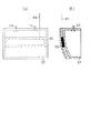
図3(a)、(b)に示すように、各イニシエータ60は、タイヤ20が跳ね上げる泥や雨水等から車体11を保護する泥除け12に設けられている。泥除け12は、ボルト14で車体11に固定される。この泥除け12は、非金属体、例えば合成樹脂等の絶縁体で構成されているため、送信機30からの電波が金属体の影響を受けることはほとんどない。その結果、受信機40の受信性能が著しく低下することもほとんどない。なお、このイニシエータ60は、フェライトコアに電線を所定回数だけ巻回した送信コイルと、共振周波数に同調させるためのコンデンサとから構成されている。そして、このイニシエータ60は、タイヤ20と対向する泥除け12の面に設けられている。
【0019】
図4に示すように、受信機40は、受信アンテナ41を介して受信されたデータを処理するためのコントローラ44及び受信回路45を備えている。マイクロコンピュータ等よりなるコントローラ44は、例えば、CPU、ROM及びRAMを備えている。受信回路45は、各送信機30からの送信データを、受信アンテナ41を介して受信する。また、受信回路45は、受信データを復調及び復号した後、コントローラ44に送出する。
【0020】
コントローラ44は、受信データに基づいて発信元の送信機30に対応するタイヤ20の空気圧を把握する。また、コントローラ44は、空気圧に関するデータを表示器50に表示させる。特に、タイヤ20の空気圧が異常である場合には、その旨を表示器50に警告表示する。
【0021】
また、受信機40は、各送信機30に対応するイニシエータ60を駆動するイニシエータ駆動回路46を備えている。イニシエータ駆動回路46は、コントローラ44で制御され、各送信機30に対応するイニシエータ60から定期的(例えば15秒間隔)にトリガ信号を無線送信させる。なお、各イニシエータ60が他のイニシエータ60と異なるタイミングでトリガ信号を無線送信するように、各イニシエータ60の送信タイミングが調整されている。従って、各イニシエータ60のうちの2つ以上が同時にトリガ信号を無線送信することはない。
【0022】
ここで、トリガ信号には、長波帯(LF:30kHz〜300kHz)の電波を使用している。これは、トリガ信号が車両10等に反射して反射波が発生する場合があり得ることを想定しているのである。すなわち、長波帯であれば、車両10等からの反射波の干渉を受けにくいことが確認されているからである。このため、送信機30のトリガ信号受信アンテナ36は、タイヤ20の全回転角度の範囲でトリガ信号を受信することができる。従って、車両10の走行中であっても、送信機30と受信機40との間でタイヤ20の状態を示すデータを送受信することができる。
【0023】
さらに、長波帯であれば、イニシエータ駆動回路46の出力を容易に制限することができるため、各イニシエータ60から発信されるトリガ信号の到達距離を制限することができる。すなわち、イニシエータ60に対応する送信機30のみにトリガ信号を検出させることができるように、イニシエータ駆動回路46の出力を制限しているのである。このため、イニシエータ60から発信されるトリガ信号は、対応する送信機30のみで検出される。従って、受信機40は、トリガ信号に応答した送信機30から送信されたデータを、受信アンテナ41を介して受信すると、送信機30が装着されているタイヤ20の取付位置を容易に特定することができる。
【0024】
次に、タイヤ状態監視装置1の動作について説明する。
まず、受信機40のコントローラ44からの制御により、いずれかのイニシエータ60がトリガ信号を無線送信すると、対応する送信機30のトリガ信号受信アンテナ36を介してトリガ信号検出回路35でトリガ信号が検出される。トリガ信号検出回路35は、トリガ信号が検出された旨をコントローラ31に送出する。コントローラ31は、圧力センサ32にタイヤ20内の空気圧を計測させ、その計測によって得られた空気圧データをコントローラ31に出力する。コントローラ31は、空気圧データを含むデータを送信回路33に出力する。送信回路33は、コントローラ31からのデータを符号化及び変調した後、そのデータを送信アンテナ34を介して無線送信する。
【0025】
受信機40は、送信機30から送信されたデータを、受信アンテナ41を介して受信すると、トリガ信号に応答した送信機30からのデータと判断する。その結果、受信機40は、トリガ信号に応答した送信機30が装着されているタイヤ20の取付位置を特定することができる。
【0026】
以上、詳述したように本実施形態によれば、次のような作用、効果を得ることができる。
(1)イニシエータ60は、非金属体で構成された泥除け12に設けられている。すなわち、イニシエータ60は、車体11等の金属体と離間された非金属体の泥除け12に設けられている。このため、送信機30からの電波が金属体の影響を受けて、受信機40の受信性能が著しく低下することはない。従って、送信機30は、タイヤ20の状態を示すデータを得るためのトリガ信号を検出することができ、そのデータを受信機40に無線送信することができる。その結果、送信機30と受信機40との間でタイヤ20の状態を示すデータを確実に送受信することができる。
【0027】
(2)イニシエータ60をタイヤ20と対向する泥除け12の面に設けている。このため、イニシエータ60が車両10の後方から見られることはない。従って、車両10自体の意匠を損なうことなく、イニシエータ60を設置することができる。
【0028】
(3)トリガ信号には、長波帯(LF:30kHz〜300kHz)の電波を使用している。このため、反射波が発生しても、反射波の干渉を受けにくい。また、送信機30のトリガ信号受信アンテナ36は、タイヤ20の全回転角度の範囲でトリガ信号を受信することができる。従って、車両10の走行中であっても、送信機30と受信機40との間でタイヤ20の状態を示すデータを送受信することができる。
【0029】
(4)イニシエータ駆動回路46の出力を制限して、各イニシエータ60から発信されるトリガ信号の到達距離を制限している。すなわち、イニシエータ60に対応する送信機30のみにトリガ信号を検出させることができるように、イニシエータ駆動回路46の出力を制限している。このため、イニシエータ60から発信されるトリガ信号は、対応する送信機30のみで検出される。従って、受信機40は、トリガ信号に応答した送信機30から送信されたデータを、受信アンテナ41を介して受信すると、送信機30が装着されているタイヤ20の取付位置を容易に特定することができる。
【0030】
なお、前記実施形態は、次のように変更して具体化することも可能である。
・図5(a)、(b)に示すように、イニシエータ60を泥除け12に内蔵した構成にしても良い。この場合、泥除け12を形成する2枚の樹脂シートでイニシエータ60を挟持した構成にしても良いし、泥除け12の形成時にイニシエータ60を一体的に埋め込んでも良い。このように構成すれば、イニシエータ60が外部から全く見えない。このため、泥除け12の意匠を損なうことなく、送信機30はイニシエータ60からのトリガ信号を安定して検出することができる。また、イニシエータ60が外部に晒されないため、イニシエータ60の損傷や劣化を確実に防止することができる。
【0031】
・イニシエータ60をPP(ポリプロピレン)、ABS樹脂等の絶縁体で成形されたサイドスポイラ、すなわちタイヤ20と最も近接するサイドスポイラの部分に設けた構成にしても良い。
【0032】
・また、イニシエータ60をPP(ポリプロピレン)、ABS樹脂等の絶縁体で成形されたリヤアンダースポイラ、すなわちタイヤ20と最も近接するリヤアンダースポイラの部分に設けた構成にしても良い。
【0033】
・車両10が四輪駆動車等のようにサイドステップを装備している場合は、イニシエータ60をサイドステップの樹脂モール等の非金属体に設けても良い。
・タイヤ20の空気圧が異常である場合には、その旨を音で報知する報知器を設けても良い。加えて、予め車両10に装備されているスピーカを報知器とする構成にしても良い。
【0034】
・送信機30から送信される空気圧データとしては、空気圧の値を具体的に示すデータ、または単に空気圧が許容範囲内であるか否かを示すデータであっても良い。
【0035】
・送信機30に温度センサを設け、空気圧データ及びタイヤ20内の温度データをタイヤの状態を示すデータとして送信機30から無線送信する構成にしても良い。
【0036】
・車両としては、4輪の車両に限らず、2輪の自転車やオートバイ、多輪のバスや被牽引車、またはタイヤを装備する産業車両(例えばフォークリフト)等に、前記実施形態を適用しても良い。なお、被牽引車に前記実施形態を適用する場合には、受信機40や表示器50を牽引車に設置することは言うまでもない。
【0037】
・多輪のトラックやバス、被牽引車等の大型車両に装着されているゴム製の泥除け部、すなわちタイヤ20と最も近接する泥除けのゴム部分にイニシエータ60を設けた構成にしても良い。
【0038】
さらに、上記実施形態より把握される技術的思想について、以下にそれらの効果と共に記載する。
〔1〕請求項1〜請求項3のいずれか1項に記載のタイヤ状態監視装置において、トリガ信号発信手段を車両の後方から見えない位置に設けたタイヤ状態監視装置。このように構成すれば、車両自体の意匠を損なうことはない。
【0039】
〔2〕請求項2〜請求項5、前記〔1〕のいずれか1項に記載のタイヤ状態監視装置において、トリガ信号発信手段を泥除けに内蔵したタイヤ状態監視装置。このように構成すれば、トリガ信号発信手段が外部から全く見えない。このため、泥除けの意匠を損なうことなく、送信機はトリガ信号発信手段からのトリガ信号を安定して検出することができる。また、トリガ信号発信手段が外部に晒されないため、トリガ信号発信手段の損傷や劣化を確実に防止することができる。
【0040】
【発明の効果】
本発明は、以上のように構成されているため、次のような効果を奏する。
請求項1〜請求項5のいずれか1項に記載の発明によれば、タイヤの状態を示すデータを得るためのトリガ信号を検出することができる。
【図面の簡単な説明】
【図1】タイヤ状態監視装置を示すブロック構成図。
【図2】送信機を示すブロック構成図。
【図3】(a)泥除けに設けた受信アンテナを示す正面図。
(b)泥除けに設けた受信アンテナを示す右側面図。
【図4】受信機を示すブロック構成図。
【図5】(a)泥除けの内部に設けた受信アンテナの例を示す正面図。
(b)泥除けの内部に設けた受信アンテナの例を示す断面図。
【符号の説明】
1…タイヤ状態監視装置、10…車両、12…泥除け、20…タイヤ、30…送信機、35…トリガ信号検出手段としてのトリガ信号検出回路、40…受信機、41…受信アンテナ、60…トリガ信号発信手段としてのイニシエータ。[0001]
BACKGROUND OF THE INVENTION
The present invention relates to a tire condition monitoring apparatus, and more particularly to a wireless tire condition monitoring apparatus capable of confirming a tire condition such as tire pressure from a passenger compartment.
[0002]
[Prior art]
In recent years, a wireless tire condition monitoring device has been proposed in order to check the condition of a plurality of tires mounted on a vehicle in a passenger compartment. The monitoring device includes a plurality of transmitters mounted on tire wheels and a receiver provided on the vehicle body. Each transmitter measures the state of the corresponding tire, such as air pressure and temperature, and wirelessly transmits data indicating the measured state. On the other hand, the receiver receives the data from the transmitter with the antenna, and displays the data indicating the state of each tire on a display provided in the driver's seat of the vehicle, for example, and stores it in the nonvolatile memory. When a transmission request signal is received from a predetermined external communication device (initiator), the receiver wirelessly transmits the data stored in the nonvolatile memory to the external communication device. Therefore, various data such as air pressure data can be easily extracted from the receiver to the external communication device (see Patent Document 1).
[0003]
[Patent Document 1]
Japanese Patent Laid-Open No. 2001-108551
[Problems to be solved by the invention]
However, in Patent Document 1, a predetermined external communication device is used to obtain various data such as air pressure data. For this reason, in order to obtain various data, a predetermined external communication device is an essential condition. Moreover, in Patent Document 1, it is considered that it is in a state where the vehicle is stopped, assuming that various types of data are taken out to the external communication device. For this reason, it is not necessary to consider the mounting position of the antenna in the external communication device. In addition, since the vehicle is in a stopped state, it is not necessary to consider the radio frequency exchanged between the receiver and the external communication device. However, in consideration of transmission and reception during travel of the vehicle, it is necessary to consider the antenna mounting position and the radio frequency in the external communication device.
[0005]
The present invention has been made paying attention to such problems, and an object thereof is to provide a tire condition monitoring apparatus capable of detecting a trigger signal for obtaining data indicating the condition of a tire. There is.
[0006]
[Means for Solving the Problems]
In order to achieve the above object, according to the first aspect of the present invention, a transmitter provided on a tire of a vehicle for wirelessly transmitting data indicating the state of the tire, and data transmitted from the transmitter are transmitted to the vehicle. A tire condition monitoring device including a receiver that receives the received data and processes the received data, the receiver transmitting a trigger signal for obtaining data indicating the tire condition The transmitter includes a transmitter, the trigger signal transmitter is provided in a non-metal body of the vehicle close to the tire, and the transmitter includes a trigger signal detector that detects the trigger signal transmitted from the trigger signal transmitter.
[0007]
According to a second aspect of the present invention, in the tire condition monitoring device according to the first aspect, the non-metal body is a mudguard.
According to a third aspect of the present invention, in the tire condition monitoring apparatus according to the first or second aspect, the trigger signal transmitting means is built in the mudguard.
[0008]
According to a fourth aspect of the present invention, in the tire condition monitoring device according to any one of the first to third aspects, a long wave radio wave is used as the trigger signal.
According to a fifth aspect of the present invention, in the tire condition monitoring device according to any one of the first to fourth aspects, the receiver is attached to the transmitter based on reception of data indicating the tire condition. The mounting position of the used tire is specified.
[0009]
DETAILED DESCRIPTION OF THE INVENTION
Hereinafter, an embodiment in which a tire condition monitoring device according to the present invention is embodied in a vehicle such as an automobile will be described with reference to the drawings.
[0010]
As shown in FIG. 1, the tire condition monitoring device 1 includes four
[0011]
Each
[0012]
The
[0013]
The
The
[0014]
As shown in FIG. 2, each
[0015]
The
[0016]
The trigger
[0017]
The
[0018]
As shown in FIGS. 3A and 3B, each
[0019]
As shown in FIG. 4, the
[0020]
The
[0021]
The
[0022]
Here, a radio wave of a long wave band (LF: 30 kHz to 300 kHz) is used as the trigger signal. This assumes that the trigger signal may be reflected on the
[0023]
Furthermore, since the output of the
[0024]
Next, the operation of the tire condition monitoring device 1 will be described.
First, when one of the
[0025]
When receiving the data transmitted from the
[0026]
As described above, according to the present embodiment, the following operations and effects can be obtained.
(1) The
[0027]
(2) The
[0028]
(3) A long wave (LF: 30 kHz to 300 kHz) radio wave is used for the trigger signal. For this reason, even if a reflected wave occurs, it is difficult to receive interference of the reflected wave. Further, the trigger
[0029]
(4) The output of the
[0030]
In addition, the said embodiment can also be changed and actualized as follows.
As shown in FIGS. 5A and 5B, the
[0031]
The
[0032]
Further, the
[0033]
When the
-When the air pressure of the
[0034]
The air pressure data transmitted from the
[0035]
The
[0036]
The vehicle is not limited to a four-wheeled vehicle, and the embodiment is applied to a two-wheeled bicycle or motorcycle, a multi-wheeled bus or a towed vehicle, or an industrial vehicle (for example, a forklift) equipped with tires. Also good. In addition, when applying the said embodiment to a towed vehicle, it cannot be overemphasized that the
[0037]
A configuration in which the
[0038]
Furthermore, the technical idea grasped from the above embodiment will be described below together with the effects thereof.
[1] The tire condition monitoring apparatus according to any one of claims 1 to 3, wherein the trigger signal transmitting means is provided at a position where it cannot be seen from the rear of the vehicle. If comprised in this way, the design of vehicle itself will not be spoiled.
[0039]
[2] The tire condition monitoring apparatus according to any one of [2] to [5] and [1], wherein the trigger signal transmitting means is built in the mudguard. If comprised in this way, a trigger signal transmission means cannot be seen at all from the outside. For this reason, the transmitter can stably detect the trigger signal from the trigger signal transmitting means without impairing the mudguard design. Further, since the trigger signal transmitting means is not exposed to the outside, it is possible to reliably prevent the trigger signal transmitting means from being damaged or deteriorated.
[0040]
【The invention's effect】
Since this invention is comprised as mentioned above, there exist the following effects.
According to the invention described in any one of claims 1 to 5, a trigger signal for obtaining data indicating a tire state can be detected.
[Brief description of the drawings]
FIG. 1 is a block diagram showing a tire condition monitoring device.
FIG. 2 is a block diagram showing a transmitter.
FIG. 3A is a front view showing a receiving antenna provided in the mudguard.
(B) The right view which shows the receiving antenna provided in mudguard.
FIG. 4 is a block diagram showing a receiver.
FIG. 5A is a front view showing an example of a receiving antenna provided inside the mudguard.
(B) Sectional drawing which shows the example of the receiving antenna provided in the inside of a mudguard.
[Explanation of symbols]
DESCRIPTION OF SYMBOLS 1 ... Tire condition monitoring apparatus, 10 ... Vehicle, 12 ... Mudguard, 20 ... Tire, 30 ... Transmitter, 35 ... Trigger signal detection circuit as trigger signal detection means, 40 ... Receiver, 41 ... Reception antenna, 60 ... Trigger Initiator as a signal transmission means.
Claims (5)
その送信機から送信されてきたデータを車両に設けた受信アンテナで受信して、受信データを処理する受信機とを備えたタイヤ状態監視装置であって、
受信機は、タイヤの状態を示すデータを得るためのトリガ信号を発信するトリガ信号発信手段を備え、トリガ信号発信手段は、タイヤに近接する車両の非金属体に設けられ、
送信機は、トリガ信号発信手段から発信されたトリガ信号を検出するトリガ信号検出手段を備えたタイヤ状態監視装置。A transmitter provided on a tire of a vehicle and wirelessly transmitting data indicating a tire state;
A tire condition monitoring device including a receiver that receives data transmitted from the transmitter by a receiving antenna provided in a vehicle and processes the received data,
The receiver includes a trigger signal transmitting means for transmitting a trigger signal for obtaining data indicating the state of the tire, and the trigger signal transmitting means is provided in a non-metal body of the vehicle adjacent to the tire,
The transmitter is a tire condition monitoring device including trigger signal detection means for detecting a trigger signal transmitted from the trigger signal transmission means.
非金属体は、泥除けであるタイヤ状態監視装置。In the tire condition monitoring device according to claim 1,
The non-metallic body is a tire condition monitoring device that is mudguard.
トリガ信号発信手段を泥除けに内蔵したタイヤ状態監視装置。In the tire condition monitoring device according to claim 1 or 2,
Tire condition monitoring device with built-in trigger signal transmission means.
トリガ信号には、長波帯の電波を使用しているタイヤ状態監視装置。In the tire condition monitoring device according to any one of claims 1 to 3,
A tire condition monitoring device that uses long-wave radio waves as trigger signals.
受信機は、タイヤの状態を示すデータの受信に基づいて、送信機が装着されているタイヤの取付位置を特定するタイヤ状態監視装置。In the tire condition monitoring device according to any one of claims 1 to 4,
The receiver is a tire condition monitoring device that identifies a mounting position of a tire on which a transmitter is mounted based on reception of data indicating a tire condition.
Priority Applications (3)
| Application Number | Priority Date | Filing Date | Title |
|---|---|---|---|
| JP2002375025A JP2004203225A (en) | 2002-12-25 | 2002-12-25 | Monitor for tire condition |
| US10/738,588 US20040135681A1 (en) | 2002-12-25 | 2003-12-15 | Tire condition monitoring apparatus |
| EP03028688A EP1433626A3 (en) | 2002-12-25 | 2003-12-16 | Tire condition monitoring apparatus |
Applications Claiming Priority (1)
| Application Number | Priority Date | Filing Date | Title |
|---|---|---|---|
| JP2002375025A JP2004203225A (en) | 2002-12-25 | 2002-12-25 | Monitor for tire condition |
Publications (1)
| Publication Number | Publication Date |
|---|---|
| JP2004203225A true JP2004203225A (en) | 2004-07-22 |
Family
ID=32463554
Family Applications (1)
| Application Number | Title | Priority Date | Filing Date |
|---|---|---|---|
| JP2002375025A Pending JP2004203225A (en) | 2002-12-25 | 2002-12-25 | Monitor for tire condition |
Country Status (3)
| Country | Link |
|---|---|
| US (1) | US20040135681A1 (en) |
| EP (1) | EP1433626A3 (en) |
| JP (1) | JP2004203225A (en) |
Cited By (4)
| Publication number | Priority date | Publication date | Assignee | Title |
|---|---|---|---|---|
| JP2006207473A (en) * | 2005-01-28 | 2006-08-10 | Hitachi Ltd | Exhaust gas diagnosis system and vehicle control system |
| JP2010030449A (en) * | 2008-07-29 | 2010-02-12 | Nippon Soken Inc | Trigger unit mounting structure for tire air pressure detector |
| KR101164482B1 (en) | 2009-07-22 | 2012-07-20 | (주)인투비 | wireless communcation in car exhaust monitoring system |
| JP2017165146A (en) * | 2016-03-14 | 2017-09-21 | 株式会社オートネットワーク技術研究所 | Communication system and communication device |
Families Citing this family (8)
| Publication number | Priority date | Publication date | Assignee | Title |
|---|---|---|---|---|
| GB0319548D0 (en) * | 2003-08-20 | 2003-09-24 | Trw Ltd | Tyre pressure monitoring apparatus |
| US20050274442A1 (en) * | 2004-06-14 | 2005-12-15 | Asia Pacific Microsystems, Inc. | Wireless tire pressure and temperature monitoring system |
| JP2006007902A (en) * | 2004-06-24 | 2006-01-12 | Denso Corp | Tire state monitoring device |
| JP2006062516A (en) * | 2004-08-26 | 2006-03-09 | Pacific Ind Co Ltd | Tire condition monitoring device, transmission device, and receiving device |
| JP2008074163A (en) * | 2006-09-19 | 2008-04-03 | Denso Corp | Tire air pressure detecting device |
| JP4544296B2 (en) * | 2007-12-10 | 2010-09-15 | 株式会社日本自動車部品総合研究所 | Trigger machine mounting structure in wheel position detector |
| CN102275470B (en) * | 2010-06-13 | 2013-10-16 | 顾向东 | Method for transferring tyre pressure by use of radio |
| EP3543041B1 (en) * | 2017-10-30 | 2021-11-24 | Pacific Industrial Co., Ltd. | Tire state detection device |
Family Cites Families (6)
| Publication number | Priority date | Publication date | Assignee | Title |
|---|---|---|---|---|
| DE4134411C2 (en) * | 1991-10-17 | 1997-01-16 | Hofmann Werkstatt Technik | Method and device for measuring wheel positions on a motor vehicle |
| US6304172B1 (en) * | 1998-11-27 | 2001-10-16 | Pacific Industrial Co., Ltd. | Receiver of tire inflation pressure monitor |
| DE19939800C2 (en) * | 1999-08-21 | 2001-09-13 | Continental Ag | System for a motor vehicle with an electronic unit located on a wheel and excitation coils arranged outside the wheel |
| US6667687B1 (en) * | 2000-11-14 | 2003-12-23 | Trw Inc. | Tire condition sensor communication with duty-cycled, amplified tire-side reception |
| JP2003165313A (en) * | 2001-11-28 | 2003-06-10 | Pacific Ind Co Ltd | Tire condition monitoring device |
| US6838985B2 (en) * | 2002-03-25 | 2005-01-04 | Lear Corporation | System and method for remote tire pressure monitoring with low frequency initiation |
-
2002
- 2002-12-25 JP JP2002375025A patent/JP2004203225A/en active Pending
-
2003
- 2003-12-15 US US10/738,588 patent/US20040135681A1/en not_active Abandoned
- 2003-12-16 EP EP03028688A patent/EP1433626A3/en not_active Withdrawn
Cited By (6)
| Publication number | Priority date | Publication date | Assignee | Title |
|---|---|---|---|---|
| JP2006207473A (en) * | 2005-01-28 | 2006-08-10 | Hitachi Ltd | Exhaust gas diagnosis system and vehicle control system |
| JP2010030449A (en) * | 2008-07-29 | 2010-02-12 | Nippon Soken Inc | Trigger unit mounting structure for tire air pressure detector |
| KR101164482B1 (en) | 2009-07-22 | 2012-07-20 | (주)인투비 | wireless communcation in car exhaust monitoring system |
| JP2017165146A (en) * | 2016-03-14 | 2017-09-21 | 株式会社オートネットワーク技術研究所 | Communication system and communication device |
| WO2017159250A1 (en) * | 2016-03-14 | 2017-09-21 | 株式会社オートネットワーク技術研究所 | Communication system and communication apparatus |
| US10266018B2 (en) | 2016-03-14 | 2019-04-23 | Autonetworks Technologies, Ltd. | Communication system and communication apparatus |
Also Published As
| Publication number | Publication date |
|---|---|
| EP1433626A3 (en) | 2006-01-25 |
| EP1433626A2 (en) | 2004-06-30 |
| US20040135681A1 (en) | 2004-07-15 |
Similar Documents
| Publication | Publication Date | Title |
|---|---|---|
| US7253726B2 (en) | Tire condition monitoring apparatus, transmitter, and receiver | |
| KR100537739B1 (en) | Transmitter of tire condition monitoring apparatus and tire condition monitoring apparatus | |
| EP1524133B1 (en) | Transmitter for tire condition monitoring apparatus | |
| US20040172179A1 (en) | Transmitter of tire condition monitoring apparatus and tire condition monitoring apparatus | |
| US7034672B2 (en) | Tire sensor | |
| JP2004149093A (en) | Tire state monitor device | |
| JP2003175711A (en) | Tire state monitoring device | |
| US6885292B2 (en) | Tire condition monitoring apparatus | |
| JP2005001498A (en) | Tire state monitor and transmitter therefor | |
| JP4050999B2 (en) | Tire condition monitoring device | |
| JP3949568B2 (en) | Transponder for tire condition monitoring device | |
| JP2004203225A (en) | Monitor for tire condition | |
| JP2004299463A (en) | Tire condition monitoring device | |
| JP2003165313A (en) | Tire condition monitoring device | |
| KR200450432Y1 (en) | Sensor for Tire Pressure and Tire Pressure Monitoring System having the same | |
| JP6131198B2 (en) | Tire condition monitoring device | |
| CN101400528B (en) | Vehicle comprising at least one assembled entity and use of a measurement system | |
| JP2000127721A (en) | Automobile and method of preventing chain of accidents of automobile |