JP2004144512A - Occupant detection system - Google Patents
Occupant detection system Download PDFInfo
- Publication number
- JP2004144512A JP2004144512A JP2002307030A JP2002307030A JP2004144512A JP 2004144512 A JP2004144512 A JP 2004144512A JP 2002307030 A JP2002307030 A JP 2002307030A JP 2002307030 A JP2002307030 A JP 2002307030A JP 2004144512 A JP2004144512 A JP 2004144512A
- Authority
- JP
- Japan
- Prior art keywords
- image
- occupant
- auxiliary light
- light
- detection system
- Prior art date
- Legal status (The legal status is an assumption and is not a legal conclusion. Google has not performed a legal analysis and makes no representation as to the accuracy of the status listed.)
- Pending
Links
Images


Classifications
-
- G—PHYSICS
- G01—MEASURING; TESTING
- G01S—RADIO DIRECTION-FINDING; RADIO NAVIGATION; DETERMINING DISTANCE OR VELOCITY BY USE OF RADIO WAVES; LOCATING OR PRESENCE-DETECTING BY USE OF THE REFLECTION OR RERADIATION OF RADIO WAVES; ANALOGOUS ARRANGEMENTS USING OTHER WAVES
- G01S17/00—Systems using the reflection or reradiation of electromagnetic waves other than radio waves, e.g. lidar systems
- G01S17/02—Systems using the reflection of electromagnetic waves other than radio waves
- G01S17/04—Systems determining the presence of a target
-
- B—PERFORMING OPERATIONS; TRANSPORTING
- B60—VEHICLES IN GENERAL
- B60R—VEHICLES, VEHICLE FITTINGS, OR VEHICLE PARTS, NOT OTHERWISE PROVIDED FOR
- B60R21/00—Arrangements or fittings on vehicles for protecting or preventing injuries to occupants or pedestrians in case of accidents or other traffic risks
- B60R21/01—Electrical circuits for triggering passive safety arrangements, e.g. airbags, safety belt tighteners, in case of vehicle accidents or impending vehicle accidents
- B60R21/015—Electrical circuits for triggering passive safety arrangements, e.g. airbags, safety belt tighteners, in case of vehicle accidents or impending vehicle accidents including means for detecting the presence or position of passengers, passenger seats or child seats, and the related safety parameters therefor, e.g. speed or timing of airbag inflation in relation to occupant position or seat belt use
- B60R21/01512—Passenger detection systems
- B60R21/0153—Passenger detection systems using field detection presence sensors
- B60R21/01538—Passenger detection systems using field detection presence sensors for image processing, e.g. cameras or sensor arrays
-
- B—PERFORMING OPERATIONS; TRANSPORTING
- B60—VEHICLES IN GENERAL
- B60R—VEHICLES, VEHICLE FITTINGS, OR VEHICLE PARTS, NOT OTHERWISE PROVIDED FOR
- B60R11/00—Arrangements for holding or mounting articles, not otherwise provided for
- B60R11/02—Arrangements for holding or mounting articles, not otherwise provided for for radio sets, television sets, telephones, or the like; Arrangement of controls thereof
- B60R11/0264—Arrangements for holding or mounting articles, not otherwise provided for for radio sets, television sets, telephones, or the like; Arrangement of controls thereof for control means
-
- B—PERFORMING OPERATIONS; TRANSPORTING
- B60—VEHICLES IN GENERAL
- B60R—VEHICLES, VEHICLE FITTINGS, OR VEHICLE PARTS, NOT OTHERWISE PROVIDED FOR
- B60R11/00—Arrangements for holding or mounting articles, not otherwise provided for
- B60R11/04—Mounting of cameras operative during drive; Arrangement of controls thereof relative to the vehicle
-
- B—PERFORMING OPERATIONS; TRANSPORTING
- B60—VEHICLES IN GENERAL
- B60R—VEHICLES, VEHICLE FITTINGS, OR VEHICLE PARTS, NOT OTHERWISE PROVIDED FOR
- B60R11/00—Arrangements for holding or mounting articles, not otherwise provided for
- B60R2011/0001—Arrangements for holding or mounting articles, not otherwise provided for characterised by position
- B60R2011/0003—Arrangements for holding or mounting articles, not otherwise provided for characterised by position inside the vehicle
- B60R2011/0028—Ceiling, e.g. roof rails
Landscapes
- Engineering & Computer Science (AREA)
- Physics & Mathematics (AREA)
- Electromagnetism (AREA)
- Computer Networks & Wireless Communication (AREA)
- General Physics & Mathematics (AREA)
- Radar, Positioning & Navigation (AREA)
- Remote Sensing (AREA)
- Computer Vision & Pattern Recognition (AREA)
- Mechanical Engineering (AREA)
- Geophysics And Detection Of Objects (AREA)
- Air Bags (AREA)
- Studio Devices (AREA)
Abstract
Description
【0001】
【発明の属する技術分野】
本発明は、車両の座席に着座している乗員状態を判別する乗員検知システムに関するものである。
【0002】
【従来の技術】
従来、車室内天井に設けられたマップランプ等に撮像手段としてのCCDカメラを設け、そのCCDカメラにて自然光の下で撮影した車室内の画像に基づいて、円形テンプレートを用いて円形部分を抽出し、その抽出結果に基づいて車室内における乗員の頭部の位置を検知するようにした乗員検知システムが提案されている。(例えば、特許文献1参照。)。
【0003】
【特許文献1】
特開2001−331790号公報
【0004】
【発明が解決しようとする課題】
しかしながら、上述した特許文献1に記載された乗員検知システムでは、周囲の明るさの変化に影響されることなく、明るさの安定した画像を得ることが困難であるという問題がある。すなわち、朝夕等においては、太陽光が斜めに車室内に差し込んで、撮影対象が明るくなり過ぎるために画像が白くなる場合がある。一方、夜間は車室内の明るさが不足して撮影が困難であると考えられる。そこで、このような状況に対応するため、夜間の暗い条件下では、絞りを大きくすると共に補助光を投光して撮影に必要な明るさを確保し、昼間の明るい条件下では、補助光を使用することなく、絞りを小さくするという方法が考えられる。この場合、夜間に対向車のヘッドライトの光が車室内に差し込む場合、光が差し込む直前は補助光が必要であるのに対し、ヘッドライトの光が差し込んだ瞬間に絞りを小さくする必要がある。同様に、朝夕の斜光が車室内に差し込む場合も、瞬間的に絞りを小さくする必要がある。しかしながら、このような急激な明るさの変化に対応して絞りを変化させたり、補助光のオン・オフを行うことは極めて困難であるため、明るさの安定した画像を得ることができないという問題がある。
【0005】
本発明は、上述した問題点に鑑みてなされたものであり、周囲の明るさの変化に影響されることなく、常に明るさの安定した画像に基づいて乗員状態を検知することが可能な乗員検知システムを提供することを解決すべき課題とする。
【0006】
【課題を解決するための手段】
この目的を達成するために、請求項1に記載の乗員検知システムは、車両座席を含む車室内所定領域へ所定の波長領域の補助光を投光する補助光投光手段と、前記車室内所定領域における少なくとも可視光の一部がカットされた画像を撮影する画像撮影手段と、前記車室内所定領域における前記画像に画像処理を施すことによって前記車両座席における乗員状態を検知する画像処理手段と、を備えたことを特徴とする。
【0007】
従って、補助光投光手段は、車両座席を含む車室内所定領域へ所定の波長領域の補助光を投光し、画像撮影手段は、補助光投光手段によって補助光が投光された前記車室内所定領域における少なくとも可視光の一部がカットされた画像を撮影し、画像処理手段は、前記画像撮影手段によって撮影された前記車室内所定領域における前記画像に画像処理を施すことによって前記車両座席における乗員状態を検知する。
【0008】
よって、補助光投光手段によって車両座席を含む車室内所定領域へ所定の波長領域の補助光が投光された状態で、画像撮影手段によって可視光の一部がカットされた画像を撮影するので、太陽光やヘッドライト、街灯等の光に含まれる可視光の影響が排除されて常に明るさの安定した画像を得ることができる。そして、このような明るさの安定した画像に画像処理を施すことによって高い精度で車両座席における乗員状態を検知することができる。
【0009】
また、請求項2に記載の乗員検知システムは、前記補助光投光手段によって投光される前記所定の波長領域の補助光は、少なくとも近赤外領域の一部を含み、前記画像撮影手段は、前記補助光における少なくとも近赤外線領域の一部において分光感度を有するカメラと、そのカメラへの入射光路上に取付けられ、少なくとも近赤外領域の一部を透過させ且つ可視光の一部をカットする光学フィルタとからなることを特徴とする。
【0010】
従って、前記画像撮影手段において、光学フィルタが、少なくとも前記補助光における近赤外領域の一部を透過させ且つ可視光の一部をカットし、前記カメラが前記車室内所定領域の近赤外線領域における画像を撮影する。
【0011】
よって、車室内所定領域からの反射光及び外部光の内、光学フィルタによって可視光の一部がカットされるので、カメラによって撮影される画像の太陽光やヘッドライト、街灯等の光による影響を除去又は低減することができる。一方、少なくとも近赤外領域の一部を含む補助光による車室内所定領域における反射光は光学フィルタを透過し、カメラによって鮮明な画像として撮影することができる。
【0012】
また、請求項3に記載の乗員検知システムは、前記補助光投光手段が、前記車室内の明るさに拘らずに前記補助光を投光するように構成されたことを特徴とする。
【0013】
従って、前記補助光投光手段が、前記車室内の明るさに拘らずに前記補助光を投光するので、昼夜を問わず、常に高い精度で乗員状態を検知することができる。また、例えば、トンネル内及びトンネルを出た後においても常に前記補助光が投光されることにより、急激な明るさの変化に拘らず、高い精度で乗員状態を検知することができる。
【0014】
また、請求項4に記載の乗員検知システムは、サイドガラス、フロントガラス等の車両に設けられたガラス部材における前記補助光の反射光が前記画像撮影手段によって撮影される画像に影響を与えないように、前記補助光投光手段における補助光の出力レベルが設定されたことを特徴とする。
【0015】
従って、サイドガラス、フロントガラス等の車両に設けられたガラス部材における前記補助光の反射光が前記画像撮影手段によって撮影される画像に影響を与えないように、前記補助光投光手段における補助光の出力レベルが設定されているので、サイドガラス等のガラス部材に車両の外部の景色が映ることがなく、誤検知の要因となる余分な画像が撮影されることを確実に防止することができる。
【0016】
また、請求項5に記載の乗員検知システムは、前記補助光投光手段が、補助光の投光領域が互いに異なるように配置された複数の光源からなり、前記各光源は、前記画像撮影手段の露光時間内において発光時間が順次切り替えられるように構成されたこと特徴とする。
【0017】
従って、投光領域が互いに異なるように配置された複数の光源によって、車室内所定領域全体に補助光が投光される。そして、各光源は、前記画像撮影手段の露光時間内において発光時間が順次切り替えられるので、露光時間全体に亘って全ての光源を同時に発光させる場合と比較して、電力消費量の低減が可能となると共に、光源の耐久性の低下を防止することができる。
【0018】
請求項6に記載の乗員検知システムは、前記画像撮影手段が、車両天井の前端部における左右方向中央部付近に設けられたことを特徴とする。
【0019】
従って、画像撮影手段が車両天井の前端部における左右方向中央部付近に設けられることにより、車両助手席又は車両運転席における車室内所定領域を確実に撮影範囲内とすることができると共に、検知対象である乗員以外の乗員を撮影範囲外とすることができるので、画像処理や乗員の頭部判別処理等が複雑化することを回避できる。また、乗員が新聞・雑誌等を広げている場合にも、乗員状態の判別に重要な乗員の頭部を確実に撮影することができる。
【0020】
請求項7に記載の乗員検知システムは、前記補助光投光手段が、車両天井の前端部における左右方向中央部付近に設けられたことを特徴とする。
【0021】
従って、前記補助光投光手段が、車両天井の前端部における左右方向中央部付近に設けられことにより、車両助手席又は車両運転席における車室内所定領域に確実に補助光を投光することができる。
【0022】
請求項8に記載の乗員検知システムは、前記画像処理手段が、前記車室内における乗員の頭部の位置を検出するように構成されたことを特徴とする。
【0023】
従って、画像処理手段が、前記車室内における乗員の頭部の位置を検出することにより、乗員の有無、大人又は子供等の乗員の種類、乗員の姿勢等、乗員の状態を確実に検知することができる。
【0024】
請求項9に記載の乗員検知システムは、前記車室内所定領域に、エアバッグの開口端付近が含まれることを特徴とする。
【0025】
従って、乗員の頭部がエアバッグの開口端付近にあるか否かを確実に判別することにより、エアバッグの展開制御を適切に行うことができる。すなわち、乗員の頭部がエアバッグの開口端付近にある状態でエアバッグが展開されると、乗員が頭部に損傷を被る可能性があるため、乗員の頭部がエアバッグの開口端付近にある場合には、エアバッグを非展開とすることによりエアバッグの安全性を向上させることができる。
【0026】
【発明の実施の形態】
以下、本発明の乗員検知システムの一実施形態について図面を参照しつつ説明する。
【0027】
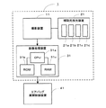
乗員検知システム1は、図1のブロック構成図に示すように、車室内の所定領域の赤外線画像を撮影する撮影装置11と、その撮影装置11によって画像が撮影される所定領域へ撮影用補助光としての赤外線を投光する補助光投光装置21と、撮影装置11によって撮影された赤外線画像に画像処理を施すことにより乗員の状態を検知し、その検知結果をエアバッグ展開制御装置41へ送信する画像処理装置31とから構成されている。
【0028】
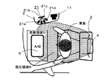
撮影装置11は、図2(a)の車室内における撮影装置11の設置領域を示す斜視図、及び同図(b)の(a)における矢印A方向から視た図に示すように、車室内天井の前端部の左右方向中央部に設けられたマップランプ2近傍から運転席上方に至るカメラ設置領域Sに設置され、車室内の助手席シート3を含む助手席ヘッドレスト4からエアバッグ開口端5に至る領域の赤外線画像が撮影されるように取付け角度が調整される。
【0029】
撮影装置11は、より具体的には、図3の分解斜視図に示すように、カメラ11aと、バンドパスフィルター11bと、レンズ11cとから構成されている。
【0030】
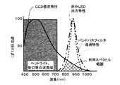
カメラ11aは、可視光から波長領域700nm〜1000nmの近赤外線までの波長領域において画像の撮影に十分な分光感度を有するCCD素子を用いたカメラである(尚、CCD感度特性については、後述する図6及び図7のグラフ参照)。
【0031】
バンドパスフィルター11bは、カメラ11aのCCD素子の前方、すなわち、CCD素子への入射光路上に取付けられ、補助光投光装置21により投光される近赤外線波長領域とほぼ同一の近赤外線波長領域のみを透過させ、それ以外の波長領域の光をカットする光学フィルターである(尚、バンドパスフィルター11bの透過特性については、後述する図6及び図7のグラフ参照)。
【0032】
レンズ11cは、バンドパスフィルター11bよりもさらに前方に取付けられ、被写体からの入射光をカメラ11aのCCD素子にて結像させる光学系部材である。
【0033】
補助光投光装置21は、撮影装置11の近傍、すなわち、マップランプ2近傍から運転席上方に至るカメラ設置領域Sに設置され、波長領域700nm〜1000nmの近赤外線を発光する光源としての4個の赤外LED21a〜21dによって構成されている。また、4個の赤外LED21a〜21dは、同時に発光することによって、図4に示すように、助手席ヘッドレスト4からエアバッグ開口端5に至る投光領域Rに赤外線が投光される。
【0034】
画像処理装置31は、各種の演算処理を行うCPU31a、画像処理プログラム及び円形テンプレート等を記憶するROM31b、ワークエリア等として使用されるRAM31c等によって構成される。CPU31aには、撮影装置11によって撮影された赤外線画像が通信線を介して入力され、画像処理を施すことによって得られた乗員状態の検知結果を、通信線を介してエアバッグ展開制御装置41へ出力する。
【0035】
エアバッグ展開制御装置41は、画像処理装置31より伝送された乗員状態の検知結果に基づいて、エアバッグの展開制御を行う。より具体的には、乗員状態の検知結果に基づいて、エアバッグの展開又は非展開、展開量を抑制する弱展開又は最大展開量とする強展開等の内、いずれの制御を行うかを決定し、エアバッグの展開制御を実行する。
【0036】
次に、本実施形態の乗員検知システム1において乗員検知を行う場合における各部の作用について説明する。
【0037】
補助光投光装置21により投光領域Rに撮影用補助光としての赤外線を投光しつつ、撮影装置11によって助手席シート3のヘッドレスト4からエアバッグ開口端5付近に至る領域の赤外線画像を撮影する。また、補助光投光装置21による赤外線の投光は、昼夜を問わず(換言すれば、周囲の明るさに拘らず)常に行われる。
【0038】
補助光投光装置21による赤外線の投光は、図5のタイミングチャートに示される通り、撮影装置11のカメラ11aによる露光タイミングと同期して行われる。また、補助光投光装置21を構成する4個の赤外LED21a〜dは同時に赤外線を投光するため、カメラ11aによる露光期間中、投光領域Rの全域に赤外線が投光される。また、補助光投光装置21による赤外線の出力は、助手席シート3のヘッドレスト4からエアバッグ開口端5付近に至る領域を赤外線撮影するのに十分なレベルであり、且つ助手席のサイドガラスやフロントガラス等のガラス部材には赤外線が殆ど届かないレベルに設定されている。このため、サイドガラス等に車両外部の景色が映ることがなく、誤検知の要因となる余分な画像が撮影装置11によって撮影されることが防止される。
【0039】
そして、補助光投光装置21によって赤外線が投光された投光領域Rにおける乗員を含む助手席シート周辺からの反射光及び外部光は、レンズ11cによってカメラ11aへ導かれ、波長領域700nm〜1000nmの近赤外線のみがバンドパスフィルター11bを透過してカメラ11aのCCD素子に入射し、これにより赤外線画像が撮影される。一方、反射光及び外部光の内、近赤外線領域以外、すなわち700nm未満及び1000nmを超える波長領域は、バンドパスフィルター11bによってカットされ、カメラ11aには入射しないため、画像には影響を与えない。
【0040】
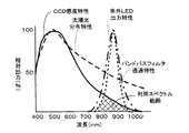
ここで、本実施形態によって、日中の太陽光入射による外乱が低減されることを図6のグラフを参照しつつ説明する。図6は、カメラ11aのCCD感度特性、バンドパスフィルター11bの透過特性、補助光投光装置21の赤外LED出力特性、及び太陽光分布特性をそれぞれ示すグラフである。図6より明らかなように、カメラ11aは可視光から近赤外線領域(波長700nm〜1000nm)までの波長領域において分光感度を有している。また、バンドパスフィルター11bは近赤外領域のみを透過し、それ以外の波長領域をカットする。また、補助光投光装置21の赤外LED21a〜21dは、近赤外線領域の光のみを出力する。従って、本実施形態における利用スペクトル範囲は、これらの重なり合った部分となり、波長領域が概ね700nm〜1000nmの範囲であることがわかる。一方、太陽光の分布特性は、図6より明らかなように、波長700nm以下の可視光領域において相対的に大きな出力を示し、近赤外領域を含む波長700nm以上では相対的に小さな出力を示している。よって、太陽光の内、相対出力の高い可視光部分がバンドパスフィルター11bによってカットされるので、朝夕の斜光によって画像が白くなって乗員が映らない等の不具合が発生することがない。また、斜光に限らず、真夏の日中等の強い明るさの下においても、上述したような不具合が発生することが防止される。
【0041】
次に、本実施形態によって、夜間のヘッドライトや街灯の光の入射による外乱が除去されることを図7のグラフを参照しつつ説明する。図7は、カメラ11aのCCD感度特性、バンドパスフィルター11bの透過特性、補助光投光装置21の赤外LED出力特性、及びヘッドライト、街灯の光の分布特性をそれぞれ示すグラフである。尚、上述した図6と重複する内容については説明を省略する。図7に示されるように、ヘッドライトや街灯の光は波長領域400nm〜700nmの可視光である。よって、ヘッドライトや街灯の光は、バンドパスフィルター11bによってほぼ完全にカットされる。従って、撮影される画像が夜間のヘッドライト、街灯等によって乗員の顔の一部が強調されたり、乗員の衣服のプリント形状が強調されてしまう等の影響を受けることがない。
【0042】
以上より、夜間等の暗い条件下から真夏の日中等の強い明るさの条件下まで、カメラ11aの絞りを変えず、且つ、感度調整を行うことなく撮影を行うことができることがわかる。つまり、夜間、急にヘッドライトの光が車室内に差し込んだり、トンネルから出た瞬間等の急激な光の変化にも影響を受けることなく画像撮影を行うことができる。
【0043】
そして、画像撮影装置11によって撮影された赤外線画像は、画像処理装置31に入力され、画像処理を施すことにより乗員状態を検知する。画像処理は、CPU31aがROM31bより画像処理プログラムを読み出して実行することにより行われる。
【0044】
画像処理では、撮影装置11より入力された赤外線画像にエッジ処理・2値化等の処理を施し、円形テンプレートとのパターンマッチングを行うことにより、助手席乗員の頭部を抽出する。そして、赤外線画像内に頭部が抽出された場合は、乗員有りと判別し、抽出されなかった場合は、乗員無しと判別される。また、抽出された頭部の大きさが所定未満である場合は、乗員が子供であると判別され、所定以上である場合は、乗員が大人であると判別される。さらに、抽出された頭部の位置が助手席エアバッグ開口端近傍の危険領域内に存在する時は、乗員が前屈みの姿勢にあって頭部が助手席エアバッグ開口端に近接する状態であると判別され、それ以外の位置に存在する時は、正常な姿勢における着座状態であると判別される。このようにして得られた乗員状態の検知結果は、通信線を介してコードの形でエアバッグ展開制御装置41に送信される。
【0045】
エアバッグ展開制御装置41は、乗員状態の検知結果を表すコードに基づいて、エアバッグの展開方法を決定し、エアバッグの展開制御を行う。例えば、検知結果が”乗員無し”の場合は、エアバッグを非展開とする。また、検知結果が、”乗員の頭部が危険領域内にある”の場合も、エアバッグを非展開とする。すなわち、乗員の頭部がエアバッグの開口端近傍の危険領域内にある場合にエアバッグを展開させると、エアバッグ展開時に乗員の頭部に強い衝撃が加わり、損傷を与える危険性が高いからである。また、検知結果が、”乗員は子供”である場合には、エアバッグを弱展開とする。その他の場合は、エアバッグを強展開とする。
【0046】
以上詳述したことから明らかなように、本実施形態によれば、補助光投光装置21によって助手席シート3を含む車室内所定領域へ所定の波長領域の補助光としての近赤外線が投光された状態で、撮影装置11によって少なくとも可視光の一部がカットされた画像を撮影するので、太陽光やヘッドライト、街灯等の光に含まれる可視光の影響が排除されて明るさの安定した画像を得ることができる。そして、このような明るさの安定した画像に、画像処理装置31において画像処理を施すことによって、高い精度で車両座席における乗員状態を検知することができる。これにより、乗員状態検知結果に基づいて、エアバッグ展開制御装置41は、適切にエアバッグの展開を制御することができる。
【0047】
また、本実施形態によれば、補助光投光装置21によって投光される所定の波長領域の補助光は、少なくとも近赤外領域の一部を含み、撮影装置11は、補助光における少なくとも近赤外線領域の一部において分光感度を有するカメラ11aと、そのカメラ11aへの入射光路上に取付けられ、少なくとも近赤外領域の一部を透過させ且つ可視光の一部をカットする光学フィルタとしてのバンドパスフィルター11bとからなる。よって、車室内所定領域からの反射光及び外部光の内、バンドパスフィルター11bによって可視光の一部がカットされるので、カメラ11aによって撮影される画像の太陽光やヘッドライト、街灯等の光による影響を除去又は低減することができる。一方、少なくとも近赤外領域の一部を含む補助光による車室内所定領域における反射光はバンドパスフィルター11bを透過し、カメラ11aによって鮮明な画像として撮影することができる。
【0048】
また、本実施形態によれば、補助光投光装置21が、車室内の明るさに拘らずに補助光としての赤外線を投光するので、昼夜を問わず、常に高い精度で乗員状態を検知することができる。また、例えば、トンネル内及びトンネルを出た後においても常に赤外線が投光されることにより、急激な明るさの変化に拘らず、高い精度で乗員状態を検知することができる。
【0049】
また、本実施形態によれば、サイドガラス、フロントガラス等の車両に設けられたガラス部材における補助光としての赤外線の反射光が撮影装置11によって撮影される画像に影響を与えないように、補助光投光装置21における補助光の出力レベルが設定されているので、サイドガラス等のガラス部材に車両の外部の景色が映ることがなく、誤検知の要因となる余分な画像が撮影されることを確実に防止することができる。
【0050】
また、本実施形態によれば、撮影装置11が、車両天井の前端部における左右方向中央部付近に設けられているので、車両助手席における車室内所定領域を確実に撮影範囲内とすることができると共に、検知対象である乗員以外の乗員(すなわち、運転席や後部座席の乗員)を撮影範囲外とすることができるので、画像処理や乗員の頭部判別処理等が複雑化することを回避できる。また、乗員が新聞・雑誌等を広げている場合にも、乗員状態の判別に重要な乗員の頭部を確実に撮影することができる。
【0051】
また、本実施形態によれば、補助光投光装置21が、車両天井の前端部における左右方向中央部付近に設けられているので、車両助手席における車室内所定領域に確実に補助光を投光することができる。
【0052】
また、本実施形態によれば、画像処理装置31が、車室内における乗員の頭部の位置を検出することにより、乗員の有無、大人又は子供等の乗員の種類、乗員の姿勢等、乗員の状態を確実に検知することができる。
【0053】
また、本実施形態によれば、車室内所定領域に、エアバッグ開口端5付近が含まれており、乗員の頭部がエアバッグ開口端5付近にあるか否かを確実に判別することにより、エアバッグの展開制御を適切に行うことができる。すなわち、乗員の頭部がエアバッグ開口端5付近にある状態でエアバッグが展開されると、乗員が頭部に損傷を被る可能性があるため、乗員の頭部がエアバッグ開口端5付近にある場合には、エアバッグを非展開とすることによりエアバッグの安全性を向上させることができる。
【0054】
また、本実施形態によれば、撮影された画像内において車両内の前後方向の位置を特定できるため、頭部を抽出した後、エアバッグ開口端5から頭部までの距離を確実に算出することができる。すなわち、助手席乗員の頭部のエアバッグ開口端5からの距離は、画像内でのエアバッグ開口端5から頭部までの距離と、実際の距離に対する画像の縮尺とから算出することができる。
【0055】
また、本実施形態によれば、1個のカメラ11aを用いてエアバッグ開口端5から頭部までの距離を算出することができるので、製造コストを低く抑えることができる。また、複雑な演算をする必要がないので、応答性にも優れている。
【0056】
次に、本発明の第二の実施形態について、図8乃至10を参照しつつ説明する。
【0057】
上述した第一の実施形態では赤外LED21a〜dを同時に発光させるように制御する構成であったが、本実施形態では、カメラ11aの露光時間内で指向性の高い赤外LED21a〜21dを順次切り替えて投光するように制御される。
【0058】
すなわち、図8に示すように、赤外LED21aは、助手席エアバッグ開口端5付近を含む第1投光領域R1に、赤外LED21bは、助手席シート3の着座部分を含む第2投光領域R2に、赤外LED21cは、助手席シート3の背もたれ部分を含む第3投光領域R3に、赤外LED21dは、助手席シート3のヘッドレスト4を含む第4投光領域R4にそれぞれ赤外線を投射するように取付け方向が調整されている。
【0059】
そして、赤外LED21a〜21dは、図9及び図10に示すように、カメラ11aの露光時間内で発光時間が順次切り替えられる。尚、図9は、第二の実施形態における赤外LEDの投光タイミングとカメラの露光タイミングとの関係を示すグラフであり、図10は、図9において破線の楕円で囲まれた部分の拡大図である。つまり、カメラ11aの露光時間内で、第1投光領域R1から第2投光領域R2、第3投光領域R3、第4投光領域R4へ順次、投光領域が切り替えられることにより、助手席ヘッドレスト4からエアバッグ開口端5に至る領域に赤外線が投光される。
【0060】
本実施形態では、第1の実施形態と比較して、各赤外LED21a〜dにおける発光時間が短いため、赤外LED21a〜dの電力消費を低減することができると共に、耐久性の低下を防止することができる。
【0061】
次に、本発明の第三の実施形態について、図11及び図12を参照しつつ説明する。
【0062】
本実施形態は、上述した第一の実施形態におけるバンドパスフィルター11bに代えて、可視光カットフィルター11dを用いる構成としたものである。本実施形態では、図11に示すように、日中において、太陽光に相対的に多く含まれる可視光領域が可視光カットフィルター11dによってカットされるため、第一の実施形態と同様に太陽光の影響を低減した画像を撮影することができる。また、図12に示すように、夜間においてヘッドライトや街灯の光が可視光カットフィルター11dによってほぼ完全にカットされるので、ヘッドライトや街灯の光による影響のない画像を撮影することができる。尚、バンドパスフィルター11bと異なり、波長1000nmを超える波長領域がカットされないが、カメラ11aは波長1000nmを超える領域において分光感度特性を有しないので、第一の実施形態とほぼ同等の画像を得ることができる。
【0063】
尚、本発明は上述した各実施形態に限定されるものではなく、本発明の主旨を逸脱しない範囲で種々の変更を施すことが可能である。
【0064】
例えば、前記各実施形態では、カメラ11aがCCD素子を用いたカメラによって構成された例を示したが、CCD素子に代えてCMOS素子を用いたカメラによって構成してもよい。要するに、近赤外線領域における分光感度特性を有する撮影装置であればよい。
【0065】
また、前記各実施形態では、助手席における乗員検知システムの例を示したが、運転席等他の車両座席における乗員検知システムに本発明を適用してもよい。
【0066】
また、前記各実施形態では、乗員状態の判別結果をエアバッグ展開制御装置41に伝送する構成としたが、他の車両乗員保護装置、例えば、プリテンショナ付きシートベルト、又はモータ等を用いて繰り返しシートベルトを巻き取る装置等の制御装置へ伝送する構成としてもよい。
【0067】
【発明の効果】
以上述べたように本発明の乗員検知システムによれば、周囲の明るさの変化に影響されることなく、常に明るさの安定した画像に基づいて乗員状態を検知することができるという効果を奏する。すなわち、補助光投光手段によって車両座席を含む車室内所定領域へ所定の波長領域の補助光が投光された状態で、画像撮影手段によって可視光の一部がカットされた画像を撮影するので、太陽光やヘッドライト、街灯等の光に含まれる可視光の影響が排除されて明るさの安定した画像を得ることができる。そして、このように明るさの安定した画像に画像処理を施すことによって高い精度で車両座席における乗員状態を検知することができる。
【図面の簡単な説明】
【図1】本発明の実施形態の乗員検知システムの全体構成を示すブロック構成図である。
【図2】(a)は車室内における撮影装置の設置領域を示す斜視図、(b)は(a)における矢印A方向から視た図である。
【図3】撮影装置の分解斜視図である。
【図4】補助光投光装置による赤外線の投光範囲を示す助手席付近の平面図である。
【図5】赤外LEDの投光タイミングとカメラの露光タイミングとの関係を示すグラフである。
【図6】太陽光入射による外乱が低減されることを示すグラフである。
【図7】ヘッドライト、街灯による外乱が除去されることを示すグラフである。
【図8】第二の実施形態における補助光投光装置による赤外線の投光範囲を示す助手席付近の平面図である。
【図9】第二の実施形態における赤外LEDの投光タイミングとカメラの露光タイミングとの関係を示すグラフである。
【図10】図9において破線の楕円で囲まれた部分の拡大図である。
【図11】第三の実施形態において太陽光入射による外乱が低減されることを示すグラフである。
【図12】第三の実施形態においてヘッドライト、街灯による外乱が除去されることを示すグラフである。
【符号の説明】
1…乗員検知システム、5…エアバッグ開口端、11…撮影装置(画像撮影手段)、11a…カメラ、11b…バンドパスフィルター(光学フィルタ)、11d…可視光カットフィルター(光学フィルタ)、21…補助光投光装置(補助光投光手段)、21a〜21d…赤外LED(光源)、31…画像処理装置(画像処理手段)。[0001]
TECHNICAL FIELD OF THE INVENTION
The present invention relates to an occupant detection system that determines the state of an occupant sitting on a vehicle seat.
[0002]
[Prior art]
2. Description of the Related Art Conventionally, a CCD camera as an imaging means is provided on a map lamp or the like provided on the ceiling of a vehicle interior, and a circular portion is extracted using a circular template based on an image of the vehicle interior taken by natural light with the CCD camera. An occupant detection system has been proposed which detects the position of the occupant's head in the vehicle cabin based on the extraction result. (For example, refer to Patent Document 1).
[0003]
[Patent Document 1]
JP 2001-331790 A
[0004]
[Problems to be solved by the invention]
However, the occupant detection system described in
[0005]
The present invention has been made in view of the above-described problems, and is capable of always detecting an occupant state based on an image with stable brightness without being affected by a change in ambient brightness. Providing a detection system is an issue to be solved.
[0006]
[Means for Solving the Problems]
To achieve this object, an occupant detection system according to
[0007]
Accordingly, the auxiliary light projecting means projects auxiliary light in a predetermined wavelength range to a predetermined area in the vehicle compartment including the vehicle seat, and the image photographing means executes the auxiliary light projecting by the auxiliary light projecting means. An image processing unit captures an image in which at least a part of visible light is cut in a predetermined area of the vehicle, and the image processing unit performs image processing on the image in the predetermined region of the vehicle room, which is captured by the image capturing unit. The occupant state at is detected.
[0008]
Therefore, in a state where the auxiliary light of a predetermined wavelength region is projected to a predetermined region of the vehicle interior including the vehicle seat by the auxiliary light projecting unit, an image in which a part of the visible light is cut by the image photographing unit is taken. In addition, the influence of visible light included in light such as sunlight, headlights, street lights, etc. is eliminated, and an image with constant brightness can always be obtained. By performing image processing on such an image having a stable brightness, the occupant state in the vehicle seat can be detected with high accuracy.
[0009]
The occupant detection system according to
[0010]
Therefore, in the image photographing means, the optical filter transmits at least a part of the near-infrared region in the auxiliary light and cuts a part of the visible light, and the camera operates in the near-infrared region of the predetermined region in the vehicle compartment. Take an image.
[0011]
Therefore, the visible light is partially cut by the optical filter out of the reflected light and the external light from the predetermined area in the vehicle cabin, so that the influence of sunlight, headlights, street lights, and the like on the image captured by the camera is reduced. Can be eliminated or reduced. On the other hand, reflected light in a predetermined area in the vehicle cabin due to the auxiliary light including at least a part of the near-infrared region passes through the optical filter and can be taken as a clear image by the camera.
[0012]
An occupant detection system according to a third aspect is characterized in that the auxiliary light projecting means is configured to emit the auxiliary light regardless of the brightness of the vehicle interior.
[0013]
Therefore, since the auxiliary light projecting means emits the auxiliary light regardless of the brightness of the vehicle interior, the occupant state can be always detected with high accuracy regardless of day or night. Further, for example, the auxiliary light is always emitted even in the tunnel and after leaving the tunnel, so that the occupant state can be detected with high accuracy regardless of a sudden change in brightness.
[0014]
The occupant detection system according to claim 4 is configured such that reflected light of the auxiliary light in a glass member provided on the vehicle such as a side glass or a windshield does not affect an image captured by the image capturing unit. The output level of the auxiliary light in the auxiliary light projecting means is set.
[0015]
Therefore, in order to prevent the reflected light of the auxiliary light on the glass member provided on the vehicle such as a side glass and a windshield from affecting the image captured by the image capturing unit, the auxiliary light is projected by the auxiliary light projecting unit. Since the output level is set, a scene outside the vehicle is not reflected on a glass member such as a side glass, and it is possible to reliably prevent an extra image that is a cause of erroneous detection from being captured.
[0016]
Further, in the occupant detection system according to
[0017]
Therefore, the auxiliary light is projected over the entire predetermined area in the vehicle compartment by the plurality of light sources arranged so that the light projection areas are different from each other. Since the light emission time of each light source is sequentially switched within the exposure time of the image photographing means, it is possible to reduce the power consumption as compared with the case where all the light sources emit light simultaneously over the entire exposure time. In addition, the durability of the light source can be prevented from lowering.
[0018]
An occupant detection system according to a sixth aspect is characterized in that the image photographing means is provided near a center in the left-right direction at a front end of a vehicle ceiling.
[0019]
Therefore, by providing the image photographing means near the center in the left-right direction at the front end of the vehicle ceiling, it is possible to ensure that a predetermined area in the vehicle passenger seat or the vehicle driver's seat is within the photographing range, Since the occupant other than the occupant can be set outside the photographing range, it is possible to prevent the image processing and the occupant's head discrimination processing from becoming complicated. In addition, even when the occupant is spreading newspapers, magazines, and the like, it is possible to reliably photograph the occupant's head which is important for determining the occupant state.
[0020]
An occupant detection system according to a seventh aspect is characterized in that the auxiliary light projecting means is provided near the center in the left-right direction at the front end of the vehicle ceiling.
[0021]
Therefore, since the auxiliary light projecting means is provided near the center in the left-right direction at the front end of the vehicle ceiling, it is possible to reliably emit auxiliary light to a predetermined area in the vehicle passenger seat or the vehicle driver's seat. it can.
[0022]
The occupant detection system according to claim 8, wherein the image processing means is configured to detect a position of a head of the occupant in the vehicle interior.
[0023]
Therefore, by detecting the position of the occupant's head in the vehicle interior, the image processing means can reliably detect the state of the occupant, such as the presence or absence of an occupant, the type of occupant such as an adult or a child, and the occupant's posture. Can be.
[0024]
An occupant detection system according to a ninth aspect is characterized in that the predetermined area in the vehicle cabin includes the vicinity of the open end of the airbag.
[0025]
Therefore, the deployment control of the airbag can be appropriately performed by reliably determining whether or not the head of the occupant is near the opening end of the airbag. That is, if the airbag is deployed while the occupant's head is near the open end of the airbag, the occupant may suffer damage to the head. In this case, the safety of the airbag can be improved by not deploying the airbag.
[0026]
BEST MODE FOR CARRYING OUT THE INVENTION
Hereinafter, an embodiment of an occupant detection system according to the present invention will be described with reference to the drawings.
[0027]
As shown in the block diagram of FIG. 1, the
[0028]
As shown in the perspective view of the installation area of the
[0029]
More specifically, as shown in an exploded perspective view of FIG. 3, the photographing
[0030]
The
[0031]
The band-
[0032]
The lens 11c is an optical system member that is attached further forward than the
[0033]
The auxiliary
[0034]
The
[0035]
The airbag
[0036]
Next, the operation of each unit when the occupant detection is performed in the
[0037]
An infrared image of an area from the headrest 4 of the passenger seat 3 to the vicinity of the
[0038]
The infrared light projection by the auxiliary
[0039]
Then, the reflected light and the external light from around the passenger seat including the occupant in the light projecting region R where the infrared light is projected by the auxiliary
[0040]
Here, a description will be given, with reference to the graph of FIG. 6, that the present embodiment reduces disturbance caused by daytime sunlight incidence. FIG. 6 is a graph showing CCD sensitivity characteristics of the
[0041]
Next, a description will be given, with reference to the graph of FIG. 7, that the present embodiment eliminates disturbance due to the incidence of nighttime headlights and streetlights. FIG. 7 is a graph showing CCD sensitivity characteristics of the
[0042]
From the above, it can be seen that shooting can be performed without changing the aperture of the
[0043]
Then, the infrared image captured by the
[0044]
In the image processing, the infrared image input from the photographing
[0045]
The airbag
[0046]
As is clear from the above, according to the present embodiment, the near-infrared ray as auxiliary light in a predetermined wavelength region is projected by the auxiliary
[0047]
Further, according to the present embodiment, the auxiliary light in the predetermined wavelength region emitted by the auxiliary
[0048]
In addition, according to the present embodiment, since the auxiliary
[0049]
Further, according to the present embodiment, the auxiliary light is used so that the infrared reflected light as the auxiliary light in the glass member provided on the vehicle such as the side glass and the windshield does not affect the image captured by the
[0050]
Further, according to the present embodiment, since the photographing
[0051]
Further, according to the present embodiment, the auxiliary
[0052]
Further, according to the present embodiment, the
[0053]
Further, according to the present embodiment, the vicinity of the
[0054]
Further, according to the present embodiment, since the position in the front-back direction in the vehicle can be specified in the captured image, the head is extracted, and then the distance from the
[0055]
Further, according to the present embodiment, the distance from the
[0056]
Next, a second embodiment of the present invention will be described with reference to FIGS.
[0057]
In the first embodiment described above, the
[0058]
That is, as shown in FIG. 8, the
[0059]
As shown in FIGS. 9 and 10, the emission times of the
[0060]
In the present embodiment, since the emission time of each of the
[0061]
Next, a third embodiment of the present invention will be described with reference to FIGS.
[0062]
In the present embodiment, a visible light cut filter 11d is used in place of the
[0063]
The present invention is not limited to the above-described embodiments, and various changes can be made without departing from the gist of the present invention.
[0064]
For example, in each of the above embodiments, the example in which the
[0065]
Further, in each of the above embodiments, the example of the occupant detection system in the passenger seat is shown, but the present invention may be applied to an occupant detection system in another vehicle seat such as a driver seat.
[0066]
Further, in each of the above-described embodiments, the configuration is such that the determination result of the occupant state is transmitted to the airbag
[0067]
【The invention's effect】
As described above, according to the occupant detection system of the present invention, there is an effect that the occupant state can be always detected based on an image with stable brightness without being affected by a change in ambient brightness. . That is, an image in which a part of visible light is cut by the image photographing means is taken in a state in which the auxiliary light in a predetermined wavelength region is projected to a predetermined area in the vehicle interior including the vehicle seat by the supplementary light projecting means. In addition, it is possible to obtain an image with stable brightness by eliminating the influence of visible light included in light such as sunlight, headlights, and street lamps. By performing image processing on an image having a stable brightness as described above, the occupant state in the vehicle seat can be detected with high accuracy.
[Brief description of the drawings]
FIG. 1 is a block diagram showing the overall configuration of an occupant detection system according to an embodiment of the present invention.
FIG. 2A is a perspective view showing an installation area of a photographing device in a vehicle cabin, and FIG. 2B is a view seen from a direction of an arrow A in FIG.
FIG. 3 is an exploded perspective view of the photographing device.
FIG. 4 is a plan view of the vicinity of a passenger seat showing an infrared light projection range of the auxiliary light projection device.
FIG. 5 is a graph showing a relationship between a projection timing of an infrared LED and an exposure timing of a camera.
FIG. 6 is a graph showing that disturbance due to sunlight incidence is reduced.
FIG. 7 is a graph showing that disturbance due to headlights and street lights is removed.
FIG. 8 is a plan view of the vicinity of a passenger seat showing an infrared light projection range of an auxiliary light projection device according to a second embodiment.
FIG. 9 is a graph showing a relationship between a projection timing of an infrared LED and an exposure timing of a camera in the second embodiment.
FIG. 10 is an enlarged view of a portion surrounded by a broken line ellipse in FIG. 9;
FIG. 11 is a graph showing that disturbance due to sunlight incidence is reduced in the third embodiment.
FIG. 12 is a graph showing that disturbance due to headlights and street lights is removed in the third embodiment.
[Explanation of symbols]
DESCRIPTION OF
Claims (9)
前記車室内所定領域における少なくとも可視光の一部がカットされた画像を撮影する画像撮影手段と、
前記車室内所定領域における前記画像に画像処理を施すことによって前記車両座席における乗員状態を検知する画像処理手段と、
を備えたことを特徴とする乗員検知システム。Auxiliary light projecting means for projecting auxiliary light in a predetermined wavelength region to a predetermined region in a vehicle cabin including a vehicle seat,
Image photographing means for photographing an image in which at least a part of visible light in the predetermined area in the vehicle interior is cut,
Image processing means for detecting an occupant state in the vehicle seat by performing image processing on the image in the predetermined area in the vehicle interior,
An occupant detection system comprising:
前記画像撮影手段は、前記補助光における少なくとも近赤外線領域の一部において分光感度を有するカメラと、そのカメラへの入射光路上に取付けられ、少なくとも近赤外領域の一部を透過させ且つ可視光の一部をカットする光学フィルタとからなることを特徴とする請求項1に記載の乗員検知システム。The auxiliary light in the predetermined wavelength region emitted by the auxiliary light projecting unit includes at least a part of the near infrared region,
The image photographing means includes a camera having spectral sensitivity in at least a part of a near-infrared region of the auxiliary light, and is mounted on an optical path incident on the camera, and transmits at least a part of the near-infrared region and emits visible light. The occupant detection system according to claim 1, comprising an optical filter that cuts a part of the occupant.
Priority Applications (2)
| Application Number | Priority Date | Filing Date | Title |
|---|---|---|---|
| JP2002307030A JP2004144512A (en) | 2002-10-22 | 2002-10-22 | Occupant detection system |
| US10/689,061 US20040085448A1 (en) | 2002-10-22 | 2003-10-21 | Vehicle occupant detection apparatus for deriving information concerning condition of occupant of vehicle seat |
Applications Claiming Priority (1)
| Application Number | Priority Date | Filing Date | Title |
|---|---|---|---|
| JP2002307030A JP2004144512A (en) | 2002-10-22 | 2002-10-22 | Occupant detection system |
Publications (1)
| Publication Number | Publication Date |
|---|---|
| JP2004144512A true JP2004144512A (en) | 2004-05-20 |
Family
ID=32170926
Family Applications (1)
| Application Number | Title | Priority Date | Filing Date |
|---|---|---|---|
| JP2002307030A Pending JP2004144512A (en) | 2002-10-22 | 2002-10-22 | Occupant detection system |
Country Status (2)
| Country | Link |
|---|---|
| US (1) | US20040085448A1 (en) |
| JP (1) | JP2004144512A (en) |
Cited By (7)
| Publication number | Priority date | Publication date | Assignee | Title |
|---|---|---|---|---|
| JP2006242909A (en) * | 2005-03-07 | 2006-09-14 | Toyota Central Res & Dev Lab Inc | System for discriminating part of object |
| JP2007316036A (en) * | 2006-05-29 | 2007-12-06 | Honda Motor Co Ltd | Occupant detector for vehicle |
| JP2008002827A (en) * | 2006-06-20 | 2008-01-10 | Honda Motor Co Ltd | Occupant detector |
| WO2012172865A1 (en) | 2011-06-17 | 2012-12-20 | 本田技研工業株式会社 | Occupant sensing device |
| WO2013021707A1 (en) | 2011-08-10 | 2013-02-14 | 本田技研工業株式会社 | Vehicle occupant detection device |
| JP2016041266A (en) * | 2015-10-26 | 2016-03-31 | セイコーエプソン株式会社 | Imaging apparatus |
| WO2020250932A1 (en) * | 2019-06-11 | 2020-12-17 | 株式会社小糸製作所 | Vehicle-mounted lighting device |
Families Citing this family (27)
| Publication number | Priority date | Publication date | Assignee | Title |
|---|---|---|---|---|
| AU2003902319A0 (en) | 2003-05-14 | 2003-05-29 | Garrett Thermal Systems Limited | Laser video detector |
| JP4644423B2 (en) * | 2003-09-30 | 2011-03-02 | 富士フイルム株式会社 | Color solid-state imaging device, solid-state imaging device using the color solid-state imaging device, and digital camera |
| US6944527B2 (en) * | 2003-11-07 | 2005-09-13 | Eaton Corporation | Decision enhancement system for a vehicle safety restraint application |
| US7471832B2 (en) * | 2004-02-24 | 2008-12-30 | Trw Automotive U.S. Llc | Method and apparatus for arbitrating outputs from multiple pattern recognition classifiers |
| US20060092401A1 (en) * | 2004-10-28 | 2006-05-04 | Troxell John R | Actively-illuminating optical sensing system for an automobile |
| EP2595131A3 (en) * | 2004-11-12 | 2013-06-12 | VFS Technologies Limited | Particle detector, system and method related applications |
| US7283901B2 (en) * | 2005-01-13 | 2007-10-16 | Trw Automotive U.S. Llc | Controller system for a vehicle occupant protection device |
| JP4533762B2 (en) * | 2005-01-19 | 2010-09-01 | 日立オートモティブシステムズ株式会社 | Variable transmittance window system |
| DE102006007092A1 (en) * | 2005-03-01 | 2006-09-07 | Denso Corp., Kariya | imaging device |
| US20060291697A1 (en) * | 2005-06-21 | 2006-12-28 | Trw Automotive U.S. Llc | Method and apparatus for detecting the presence of an occupant within a vehicle |
| US20070146482A1 (en) | 2005-12-23 | 2007-06-28 | Branislav Kiscanin | Method of depth estimation from a single camera |
| JP2007216722A (en) * | 2006-02-14 | 2007-08-30 | Takata Corp | Object detection system, operating device control system, and vehicle |
| JP2007218626A (en) * | 2006-02-14 | 2007-08-30 | Takata Corp | Object detecting system, operation device control system, vehicle |
| JP2008052029A (en) * | 2006-08-24 | 2008-03-06 | Takata Corp | Photographing system, vehicle crew detection system, operation device controlling system, and vehicle |
| JP4658899B2 (en) * | 2006-10-24 | 2011-03-23 | 本田技研工業株式会社 | Vehicle occupant detection device |
| JP2008129948A (en) * | 2006-11-22 | 2008-06-05 | Takata Corp | Occupant detection device, actuator control system, seat belt system, vehicle |
| JP2008261749A (en) * | 2007-04-12 | 2008-10-30 | Takata Corp | Occupant detection device, actuator control system, seat belt system, and vehicle |
| US8659698B2 (en) * | 2007-05-17 | 2014-02-25 | Ilya Blayvas | Compact 3D scanner with fixed pattern projector and dual band image sensor |
| TWI583937B (en) * | 2007-11-15 | 2017-05-21 | 愛克斯崔里斯科技有限公司 | Determining alignment of a beam in an active video smoke detection (avsd) system |
| US20120026331A1 (en) * | 2009-01-05 | 2012-02-02 | Winner Jr James E | Seat Belt Usage Indication |
| WO2013109869A1 (en) | 2012-01-20 | 2013-07-25 | Magna Electronics, Inc. | Vehicle vision system with free positional virtual panoramic view |
| US20150015706A1 (en) * | 2013-07-09 | 2015-01-15 | Honda Motor Co., Ltd. | Vehicle exterior image capturing device |
| DE102013019111B4 (en) * | 2013-11-15 | 2017-07-06 | Audi Ag | Motor vehicle and method for operating at least one radiation source |
| CN107428302B (en) | 2015-04-10 | 2022-05-03 | 罗伯特·博世有限公司 | Occupant size and pose detection with vehicle interior camera |
| WO2019176391A1 (en) * | 2018-03-15 | 2019-09-19 | 株式会社Jvcケンウッド | Drive recorder, display control method, and program |
| JP7252755B2 (en) * | 2018-12-27 | 2023-04-05 | 株式会社小糸製作所 | Active sensors, object identification systems, vehicles, vehicle lighting |
| CN112644255A (en) * | 2020-12-17 | 2021-04-13 | 广州橙行智动汽车科技有限公司 | Method and device for adjusting light transmission in vehicle, storage medium and vehicle |
Family Cites Families (3)
| Publication number | Priority date | Publication date | Assignee | Title |
|---|---|---|---|---|
| US6820897B2 (en) * | 1992-05-05 | 2004-11-23 | Automotive Technologies International, Inc. | Vehicle object detection system and method |
| DE19852653A1 (en) * | 1998-11-16 | 2000-05-18 | Bosch Gmbh Robert | Device for detecting the occupancy of a vehicle seat |
| JP3732398B2 (en) * | 2000-10-11 | 2006-01-05 | 三菱電機株式会社 | Crew protection device |
-
2002
- 2002-10-22 JP JP2002307030A patent/JP2004144512A/en active Pending
-
2003
- 2003-10-21 US US10/689,061 patent/US20040085448A1/en not_active Abandoned
Cited By (10)
| Publication number | Priority date | Publication date | Assignee | Title |
|---|---|---|---|---|
| JP2006242909A (en) * | 2005-03-07 | 2006-09-14 | Toyota Central Res & Dev Lab Inc | System for discriminating part of object |
| JP2007316036A (en) * | 2006-05-29 | 2007-12-06 | Honda Motor Co Ltd | Occupant detector for vehicle |
| JP2008002827A (en) * | 2006-06-20 | 2008-01-10 | Honda Motor Co Ltd | Occupant detector |
| JP4669445B2 (en) * | 2006-06-20 | 2011-04-13 | 本田技研工業株式会社 | Occupant detection device |
| WO2012172865A1 (en) | 2011-06-17 | 2012-12-20 | 本田技研工業株式会社 | Occupant sensing device |
| WO2013021707A1 (en) | 2011-08-10 | 2013-02-14 | 本田技研工業株式会社 | Vehicle occupant detection device |
| JP2016041266A (en) * | 2015-10-26 | 2016-03-31 | セイコーエプソン株式会社 | Imaging apparatus |
| WO2020250932A1 (en) * | 2019-06-11 | 2020-12-17 | 株式会社小糸製作所 | Vehicle-mounted lighting device |
| JPWO2020250932A1 (en) * | 2019-06-11 | 2020-12-17 | ||
| JP7406553B2 (en) | 2019-06-11 | 2023-12-27 | 株式会社小糸製作所 | In-vehicle lighting system |
Also Published As
| Publication number | Publication date |
|---|---|
| US20040085448A1 (en) | 2004-05-06 |
Similar Documents
| Publication | Publication Date | Title |
|---|---|---|
| JP2004144512A (en) | Occupant detection system | |
| JP4853389B2 (en) | Face image capturing device | |
| JP3948431B2 (en) | Vehicle periphery monitoring device | |
| US8059867B2 (en) | Detection system, informing system, actuation system and vehicle | |
| US7551987B2 (en) | Illuminating apparatus, image capturing apparatus, and monitoring apparatus, for vehicle driver | |
| US8081800B2 (en) | Detection device of vehicle interior condition | |
| US6603137B2 (en) | Differential imaging rain sensor | |
| US7278505B2 (en) | Control device for starting motion of mobile body | |
| US7295771B2 (en) | Method and apparatus for minimizing ambient illumination effects in a vision system | |
| CN101130353A (en) | Photographing system, vehicle occupant detection system, operation device controlling system, and vehicle | |
| JP7060790B2 (en) | Camera and occupant detection system | |
| JP6963563B2 (en) | Vehicle lighting system and vehicle | |
| KR100759238B1 (en) | Device for detecting whether a vehicle seat is occupied by means of a stereoscopic image recording sensor | |
| US9506803B2 (en) | Vehicle optical sensor system | |
| JP7331483B2 (en) | Imaging control device | |
| JP2007156832A (en) | On-vehicle near-infrared light irradiation device and on-vehicle periphery monitoring device | |
| EP1862358A1 (en) | Vehicle occupant detection device | |
| JP4269998B2 (en) | Imaging device | |
| JP5179428B2 (en) | Vehicle periphery monitoring device | |
| US20050151053A1 (en) | Infrared proximity sensor for air bag safety | |
| JP2004274154A (en) | Vehicle crew protector | |
| JP6572809B2 (en) | Image processing device | |
| KR102320030B1 (en) | Camera system for internal monitoring of the vehicle | |
| JP2009120008A (en) | Lighting system for photographing | |
| JP6203535B2 (en) | Rear fog lamp device |
Legal Events
| Date | Code | Title | Description |
|---|---|---|---|
| A621 | Written request for application examination |
Free format text: JAPANESE INTERMEDIATE CODE: A621 Effective date: 20041221 |
|
| A977 | Report on retrieval |
Free format text: JAPANESE INTERMEDIATE CODE: A971007 Effective date: 20050419 |
|
| A131 | Notification of reasons for refusal |
Free format text: JAPANESE INTERMEDIATE CODE: A131 Effective date: 20051227 |
|
| A521 | Request for written amendment filed |
Free format text: JAPANESE INTERMEDIATE CODE: A523 Effective date: 20060224 |
|
| A02 | Decision of refusal |
Free format text: JAPANESE INTERMEDIATE CODE: A02 Effective date: 20060407 |