JP2004086930A - Method of manufacturing magnetic disk glass substrate and magnetic disk - Google Patents
Method of manufacturing magnetic disk glass substrate and magnetic disk Download PDFInfo
- Publication number
- JP2004086930A JP2004086930A JP2002210363A JP2002210363A JP2004086930A JP 2004086930 A JP2004086930 A JP 2004086930A JP 2002210363 A JP2002210363 A JP 2002210363A JP 2002210363 A JP2002210363 A JP 2002210363A JP 2004086930 A JP2004086930 A JP 2004086930A
- Authority
- JP
- Japan
- Prior art keywords
- glass substrate
- magnetic
- magnetic disk
- manufacturing
- cleaning
- Prior art date
- Legal status (The legal status is an assumption and is not a legal conclusion. Google has not performed a legal analysis and makes no representation as to the accuracy of the status listed.)
- Pending
Links
Images


Landscapes
- Manufacturing Of Magnetic Record Carriers (AREA)
- Cleaning By Liquid Or Steam (AREA)
- Magnetic Record Carriers (AREA)
Abstract
Description
【0001】
【発明の属する技術分野】
本発明は、磁気記録媒体に関し、特に、HDD(ハードディスクドライブ)等に搭載される磁気ディスクに関する。
【0002】
【従来の技術】
今日、情報記録技術、特に磁気記録技術は、急速なIT産業の発達に伴い飛躍的な技術革新が要請されている。HDD等に搭載される磁気ディスクでは、高容量化の要請により40Gbit/in2〜100Gbit/in2以上の情報記録密度を実現できる技術が求められている。
【0003】
磁気ディスクでは、磁気記録ヘッドの浮上飛行方向の磁気特性が特に優れていることが求められる。このため、例えば特開昭62−273619号等では、アルミ合金等の金属基板表面上に磁気異方性を付与するテクスチャを形成した上で、磁性層を成膜することによって、半径方向の磁気特性に対比して、磁気記録ヘッドの浮上飛行方向の磁気特性を向上させるなどされてきた。
【0004】
ところで、近年、HDDのモバイル化、小型化の要請から、高剛性で耐衝撃性に優れ、また高い表面平滑性が得られるガラス基板が注目されている。
さらに、ガラス基板の場合であれば、耐衝撃性に優れているので、アルミ合金製基板のようにNiP等の金属膜を被着して剛性を補強する必要が無く、工程短縮できるので、廉価な磁気ディスクを提供でき、また、小型化が容易であるという利点がある。例えば、本出願人は、特開2002−32909号公報において、ガラス基板上に円周状のテクスチャを形成し、この上に磁性層等をスパッタリングした磁気記録媒体に関して開示している。
【0005】
【発明が解決しようとする課題】
ガラス基板の場合においても、半径方向の磁気特性に比べて、円周方向の磁気特性が優れていることが望まれる。例えば40Gbit/inch2以上の記録密度を達成する場合では、残留磁化膜厚積による磁気異方性比(MrtOR)は1.2以上であることが求められる。また、50Gbit/inch2以上の記録密度を得るためには、MrtORは1.3以上、特に、60Gbit/inch2以上の高記録密度領域ではMrtORは1.35以上が望ましいとされている。
【0006】
なお、上述のMrtORとは、残留磁化膜厚積(Mrt)から算出する磁気異方性比OR(Oriented Ratio)のことである。磁気記録媒体主表面上の任意の点において、円周方向の残留磁化膜厚積をMrt(c)、半径方向の残留磁化膜厚積をMrt(r)としたときに、Mrt(r)に対するMrt(c)の比Mrt(c)/Mrt(r)をMrtORとして定める。
【0007】
ここで、Mrtとは、Mr(残留磁化)とt(媒体の磁性層厚さ)との積のことである。MrtORがほぼ1であれば、円周方向と半径方向の磁気特性がほぼ等しい、等方性の磁気記録媒体である。MrtORが1を越えて大きくなるに従って、円周方向の磁気異方性が向上していることを示している。
【0008】
ところが、アルミ合金製基板や、NiP等の金属膜を被着した基板など、金属表面上に磁気異方性を付与するテクスチャを形成した場合とは異なり、ガラス基板表面上に直接、磁気異方性を付与するテクスチャを形成し、この上に磁性層を形成した場合では、MrtORは1.0〜1.1程度しか得られなかったため、HDDの高容量化と低価格化を阻害する要因となっていた。
【0009】
本発明は上記問題点に鑑みてなされたものであり、ガラス基板を用いた場合であっても1.2以上のMrtORが得られ、40Gbit/in2以上の記録密度が達成できる、耐衝撃性に優れた、廉価な磁気ディスク用ガラス基板の製造方法を提供することを目的とする。
【0010】
また、ガラス基板を用いた場合であっても1.2以上のMrtORが得られ、40Gbit/in2以上の記録密度が達成できる、耐衝撃性に優れた、廉価な磁気ディスクの製造方法を提供することを目的とする。
【0011】
【課題を解決するための手段】
(構成1)
磁性層に磁気異方性を付与するテクスチャを、ガラス基板の主表面に形成するテクスチャ工程と、前記テクスチャ工程の後に、ガラス基板の清浄工程を含む磁気ディスク用ガラス基板の製造方法において、
前記清浄工程は、pHが4.5〜14の処理液によってガラス基板のテクスチャを清浄することを含むことを特徴とする磁気ディスク用ガラス基板の製造方法。
【0012】
(構成2)
構成1記載の磁気ディスク用ガラス基板の製造方法であって、
処理液によってガラス基板のテクスチャを清浄する前に、
前記テクスチャ工程でガラス基板に付着した研磨砥粒を除去する工程を含むことを特徴とする磁気ディスク用ガラス基板の製造方法。
【0013】
(構成3)
構成1又は2に記載の磁気ディスク用ガラス基板の製造方法であって、
前記ガラス基板を構成するガラスは、アルミノシリケートガラスであることを特徴とする磁気ディスク用ガラス基板の製造方法。
【0014】
(構成4)
構成3記載の磁気ディスク用ガラス基板の製造方法であって、
前記アルミノシリケートガラスは、SiO2を58〜75重量%、Al2O3を5〜23重量%、Li2Oを3〜10重量%、Na2Oを4〜13重量%、主成分として含有するガラスであることを特徴とする磁気ディスク用ガラス基板の製造方法。
【0015】
(構成5)
構成1乃至4の何れか一に記載の磁気ディスク用ガラス基板の製造方法であって、ガラス基板上に少なくとも磁性層を形成したときに、磁性層に1.2以上の残留磁化膜厚積による磁気異方性が付与されるよう製造する磁気ディスク用ガラス基板の製造方法。
【0016】
(構成6)
構成1乃至5の何れか一に記載の磁気ディスク用ガラス基板の製造方法によって製造されたガラス基板上に少なくとも磁性層を形成する磁気ディスクの製造方法。
【0017】
(構成7)
構成6記載の磁気ディスクの製造方法であって、
ガラス基板上に前記テクスチャを形成してから磁性層を形成するまでのガラス基板の全清浄工程における処理液はpHが4.5〜14の処理液であることを特徴とする磁気ディスクの製造方法。
【0018】
(構成8)
ガラス基板上に少なくとも磁性層を形成したときに磁性層に磁気異方性を付与するテクスチャを主表面に有するガラス基板を処理液で処理し、少なくとも磁性層を形成する磁気異方性磁気ディスクの製造方法において、
予め、処理液のpHと、磁気異方性との相関関係を求めておき、
所定の磁気異方性を得るために、前記相関関係に基づいて処理液のpHを選定し、
前記選定条件に従って、ガラス基板を処理することを特徴とする磁気異方性磁気ディスクの製造方法。
【0019】
本発明者らは、磁気ディスク用ガラス基板上に直接、磁性層に磁気異方性を付与するテクスチャを形成した場合では高いMrtORが得られない原因について様々な観点から研究を行った。
【0020】
従来、磁気ディスク用ガラス基板を洗浄する工程においては、高い洗浄能力を得るために、強い酸性の洗浄液が用いられることが多かった。ここで言う強い酸性の洗浄液としては、例えば、硫酸、フッ酸、ケイフッ酸等が挙げられる。これら強い酸性による高い洗浄能力を得て、ガラス基板上からヘッドクラッシュやサーマルアスペリティ等の原因となる異物を除去している。
【0021】
しかし本願発明者らによって得られた知見によれば、前記テクスチャが形成されたガラス基板の場合においては、洗浄能力に着眼した従来のガラス基板の洗浄工程を用いてしまうと、高い磁気異方性を得る目的に対して阻害要因となる事が判明した。
【0022】
本発明者らが解明した事実では、ガラス基板上に前記テクスチャを形成した後から、磁性層を形成するまでの間に設けられている、ガラス基板の清浄工程の処理液のPHによって、MrtORが変動することが判った。
【0023】
ここで言うガラス基板の清浄工程の処理液とは、ガラス基板の洗浄工程の洗浄液、ガラス基板の保管工程の保管液、ガラス基板の搬送工程の保管液など、テクスチャの形成されたガラス基板を清浄する作用を備える処理液のことである。ガラス基板の主表面に前記テクスチャが形成されたガラス基板においては、処理液は、磁気異方性を低下させることのないよう、PHの厳密な制御を要することが判った。
【0024】
具体的には、処理液のpHを4.5〜14と選定すると、高いMrtORが得られるようになることが判明した。この場合1.2以上の高いMrtORが得られるようにする事ができるので好適である。さらに、処理液のpHを6.3〜13と選定すると特に好適である。この場合1.3以上の高いMrtORが得られるようにする事ができるからである。
【0025】
本発明者が考察するところでは、このような現象が発生する理由は以下のように考えられている。通常、アルカリ金属イオン等のプラスイオン(カチオン)を含むガラスを、液体に接触させると、液中に含まれる水素イオン(H+)が、ガラスに対してリーチング作用を働くので、ガラス表面のプラスイオンは、水素イオン(H+)と置換される。
【0026】
このリーチング作用により、ガラス基板の相対的にイオン半径の大きなアルカリ金属イオンが、液中に含まれる相対的にイオン半径の小さな水素イオンと置換されてしまうため、ガラス基板表面が侵され、ガラス基板表面に形成された、磁性層に磁気異方性を付与するための微細なテクスチャ形状を乱してしまうと考察されている。従って、テクスチャ工程後のガラス基板に接触する液体はガラス基板に対して磁気異方性を低下させるリーチング作用を働かないものが好ましいと考えられる。
【0027】
従来、磁気ディスク用ガラス基板において、リーチング作用によるガラス基板表面形状の乱れが問題とされなかった理由は、リーチング作用によるガラス基板表面の乱れが極めて微細であるので、磁気記録ヘッドの浮上特性に影響を与えたり、サーマルアスペリティ障害を発生させることがなかったためであると考えられる。
【0028】
液体に含まれる前記水素イオン(H+)の濃度は、pHにより数値化できるが、処理液のpHを4.5以上とすることにより高いMrtORが得られる理由は、pHが4.5以上の場合、前記リーチング作用が抑制できるからであると考えられる。
【0029】
次に、ガラス基板と液中に含まれる水酸基イオン(OH−)との関係を考察する。水酸基イオンは、ガラスの基本骨格であるSi−Oの共有結合を浸食するエッチング作用を備えると考えられるので、水酸基イオンが過多になると、ガラス基板表面に形成された、磁性層に磁気異方性を付与するための微細なテクスチャ形状を乱してしまうと考えられる。従って、テクスチャ工程後のガラス基板に接触する液体はガラス基板に対して磁気異方性を低下させるエッチング作用を働かないものが好ましいと考えられる。
【0030】
従来、磁気ディスク用ガラス基板において、水酸基イオンのエッチング作用によるガラス基板表面形状の乱れが問題とされなかった理由は、ガラス基板表面の乱れが極めて微細であるので、磁気記録ヘッドの浮上特性に影響を与えたり、サーマルアスペリティ障害を発生させることがなかったためであると考えられる。
【0031】
液体に含まれる前記水酸基イオン(OH−)の濃度は、pHにより数値化できるが、処理液のpHを13以下とすることにより高いMrtORが得られる理由は、pHが13以下の場合、前記水酸基イオンによるエッチング作用が抑制できるからであると考えられる。
【0032】
処理液のpHを中性に近づける程、ガラス基板に対するリーチング作用やエッチング作用は抑制されるので好ましい。
但し、洗浄工程の洗浄液の場合にあっては、同時に洗浄性能が低下するので、洗浄液のpHは、前述の範囲内で、好適な洗浄性能が得られるよう適宜調整するのが好ましい。
【0033】
洗浄工程の場合では、洗浄液のpHを中性に近づけると、洗浄性能が低下するので、この場合は、洗浄性能を補うために、ジェット水流による洗浄、スピン洗浄、スクラブ洗浄など物理的エネルギーを付加する洗浄手段を併用することが好ましい。洗浄液として水を用いる場合、或いは洗浄液を水で希釈する場合は超純水(DI水、RO水)等の異物対策、残留イオン対策の施された水を用いることが好ましい。このように洗浄することで、ヘッドクラッシュやサーマルアスペリティを防止しつつ、高い磁気異方性比が得られるようにできる。
【0034】
ヘッドクラッシュやサーマルアスペリティを好適に抑制し、かつ、高い磁気異方性比を得るために、処理液によってガラス基板のテクスチャを清浄する前に、前記テクスチャ工程でガラス基板に付着した研磨剤を除去する工程を備える事が好ましい。
【0035】
ガラス基板に前記テクスチャを形成するために用いる研磨剤(ダイヤモンドなどからなる研磨砥粒と、グリセリンなどからなる湿潤剤などを含む)は、ヘッドクラッシュやサーマルアスペリティの原因となる場合がある。従って、処理液によってガラス基板のテクスチャを清浄する前に研磨剤を除去しておくと、清浄工程の作用効果が高められるので好ましい。
【0036】
洗浄液による洗浄工程の前に、前記テクスチャ工程でガラス基板に付着した研磨剤を除去する工程を備えると、該洗浄液のpHを中性に近づけられるので、高い磁気異方性比を得られるようになり特に好ましい。
【0037】
ガラス基板に付着した研磨剤を除去する工程としては、超純水(RO水、DI水)でテクスチャ工程後のガラス基板をシャワー洗浄して研磨剤を除去する工程が挙げられる。
【0038】
洗浄液による洗浄工程としては、洗浄液は、KOH水溶液、NaOH水溶液、リン酸ナトリウム水溶液などが好ましい。洗浄液としてKOHを含有する洗浄液を用いる場合は、KOHが8重量%以下とすると洗浄性能が高く好適である。中でも、KOHとNaOHの両方を含有するものは、ガラス基板上のパーティクルや、油脂分、金属イオン、研磨剤の除去に優れているので特に好ましい。この場合、KOHとNaOHの含有量の比は体積%の比で、60:40〜40:60の範囲内で調整すると、洗浄性能が高く好適である。ガラス基板上に前記テクスチャを形成する工程においてダイヤモンド砥粒や、グリセリン等の湿潤剤が配合されている遊離砥粒を用いる場合に関して、これらの除去能力が高くなるので好適である。
【0039】
なお、洗浄工程における洗浄液の温度については、実用上20℃〜60℃とすることが好ましい。20℃未満の場合は洗浄能力が低く、磁気ディスク上に磁気記録ヘッドを走行たときにヘッドクラッシュやサーマルアスペリティーなどの障害を発生させる可能性がある。また60℃を越えるとガラス表面に乾きが発生するために好ましくない。
【0040】
洗浄時間については、ガラス基板の表面形状を乱さない範囲内であればよいが、実用上10秒以上でないと洗浄効果が不十分であり、また1時間を越えると生産性が低下し製造コストが増大するため好ましくない。
【0041】
本発明における洗浄工程では超音波を付加することが好ましい。超音波を付加することにより、高い洗浄効果が得られるので、ヘッドクラッシュやサーマルアスペリティ等の障害を防止することができる。
【0042】
本発明において用いるガラス基板の構成するガラスは、アルミノシリケートガラスが好適である。アルミノシリケートガラスは、前述したPHの範囲内であれば、前記リーチング作用、エッチング作用を厳密に制御することができるので、高いMrtORを得るようにすることができる。
【0043】
アルミノシリケートガラスとしては、アルカリ金属元素を含有するガラスが好ましい。アルカリ元素を含有するガラス基板は、化学強化に適し、優れたLUL特性、耐衝撃性を得ることができる。本発明ではリーチング作用が抑止されているため、アルカリ元素を含有したガラス基板であっても高いMrtORを得ることができるので好適である。
【0044】
なお、上記アルミノシリケートガラスの中でも特に、その組成比は、SiO2:58〜75重量%、Al2O3:5〜23重量%、Li2O:3〜10重量%、Na2O:4〜13重量%を主成分として含有するガラスからなることが好ましい。
【0045】
更に、前記ガラス基板の組成を、SiO2:62〜75重量%、Al2O3:5〜15重量%、Li2O:4〜10重量%、Na2O:4〜12重量%、ZrO2:5.5〜15重量%を主成分として含有するとともに、Na2O/ZrO2の重量比が0.5〜2.0、Al2O3/ZrO2の重量比が0.4〜2.5であるアルミノシリケートガラスであることが好ましい。
【0046】
また、ZrO2の未溶解物が原因で生じるガラス基板表面の突起を無くすためには、モル%表示で、SiO2を57〜74%、ZnO2を0〜2.8%、Al2O3を3〜15%、LiO2を7〜16%、Na2Oを4〜14%含有する化学強化用ガラス等を使用することが好ましい。
【0047】
このようなアルミノシリケートガラスは、化学強化することによって、抗折強度が増加し、圧縮応力層の深さも深く、ヌープ硬度にも優れるとともに、前記リーチング作用、エッチング作用の制御性においても大変優れているので、高いMrtORが得られるようになり特に好ましい。なお、上述のアルミノシリケートガラスの代表的なものとしては、HOYA株式会社製のN5が挙げられる。
【0048】
本発明において、ガラス基板は化学強化されたものであることが好ましい。化学強化されたガラス基板は、ガラス基板表面上に応力層が形成されているため、強度が高く、また平坦度も高いので、LUL特性、耐衝撃性に優れ、モバイル用途のHDDに特に好適である。
【0049】
なお、この化学強化工程は、ガラス基板表面上に前記テクスチャを形成する工程より前に施すことが好ましい。化学強化工程では、イオン交換の過程でガラス基板表面の圧縮応力分布に微小な乱れが生じたり、或いは化学強化塩がガラス基板表面に固く結着するなどして、ガラス基板の表面粗さを乱す場合がある。このため、ガラス基板上に前記テクスチャを形成した後に化学強化工程を施した場合では、磁性層に磁気異方性を付与するためのテクスチャ形状が化学強化によって乱され、所望のMrtORが得られない場合がある。従って、化学強化工程は、前記テクスチャを形成する前に施すことが好ましい。
【0050】
本発明においては、磁気ディスクの製造方法として、ガラス基板上に前記テクスチャを形成してから磁性層を形成するまでのガラス基板の全清浄工程における処理液はpHが4.5〜14の処理液であることが好ましい。このようにすることで、ガラス基板上に直接前記テクスチャを形成した場合であっても、高い1.2以上の高いMrtORを備える磁気ディスクを得られるようになるので好適である。
更に好ましくは、該処理液のPHを6.3〜13.0とすることが好ましい。このようにすることで、ガラス基板上に直接前記テクスチャを形成した場合であっても、高い1.3以上の高いMrtORを備える磁気ディスクを得られるようになるので好適である。
【0051】
本発明においては、ガラス基板上に少なくとも磁性層を形成したときに磁性層に磁気異方性を付与するテクスチャを主表面に有するガラス基板を処理液で処理し、少なくとも磁性層を形成する磁気異方性磁気ディスクの製造方法において、予め、処理液のpHと、磁気異方性との相関関係を求めておき、所定の磁気異方性を得るために、前記相関関係に基づいて処理液のpHを選定し、前記選定条件に従って、ガラス基板を処理することを特徴とする磁気異方性磁気ディスクの製造方法についても提供される。
【0052】
このように磁気ディスクを製造することにより、再現性よく所望の残留磁化膜厚積による磁気異方性比(MrtOR)を得ることができるので、磁気ディスクを大量生産した場合においても、磁気ディスク毎のMrtORのバラツキを抑制することができ、製造歩留まりを向上させることができるので、磁気ディスクの低コスト化と、低価格化を実現することができる。
【0053】
本発明において磁性層の組成は特に限定されないが、hcp結晶構造をもつCo合金からなる材料は、結晶磁気異方性が高いので好ましい。Co系合金の内、CoPt系合金の場合、3000エルステッド以上の高い保磁力を得ることのできるので、好ましい。またCoCr系合金の場合では、Crによって磁性粒子間の交換相互作用を抑制することができるので、媒体ノイズを低減することができ、好ましい。これらCo系合金としては、例えば、CoPt合金やCoCr合金の他、CoCrPt系合金、CoCrPtTa系合金、CoCrPtTaB系合金、CoCrPtB系合金、CoCrPtNb系合金などが挙げられる。これらの中でもCoCrPtB合金は媒体ノイズが低く高記録密度化に好適である。CoCrPtB合金の場合のCrの含有量として好適な範囲は13at%〜25at%、Ptの好適な含有量は、6at%〜15at%、Bの好適な含有量としては、2at%〜10at%、残部をCoとする事が好ましい。
【0054】
本発明において、ガラス基板上に形成する、磁性層に磁気異方性を付与するテクスチャは磁気記録ヘッドの浮上走行方向の磁気異方性を高められる規則性のある形態であればよいが、磁気ディスクの場合、磁気記録ヘッドの走行方向は円周方向であるので、円周状の規則性を持ったテクスチャ、あるいは、これに交差する形状成分を持つクロステクスチャ、楕円状テクスチャ、らせん状テクスチャまたはこれら形状成分の複合形態であってよい。中でも円周状のテクスチャは、磁性粒子を磁気記録ヘッドの走行方向へ配列させる作用が高いので好ましい。
【0055】
【発明の実施の形態】
本発明の一実施形態になる製造方法により製造した磁気ディスク用ガラス基板1に、成膜工程により磁性層等を形成した磁気ディスク10を図1に示す。磁気ディスク10は以下の構造を有している。
【0056】
磁気ディスク用ガラス基板1は、化学強化されたアルミノシリケートガラスに、研磨、及び円周状テクスチャ、精密洗浄が施されたガラス基板である。このガラス基板1上に、シード層2、下地層3、磁性層4、保護層5、潤滑層6が順次積層されている。シード層2はシード層2a及びシード層2bからなる。シード層2及び下地層3は非磁性層である。
【0057】
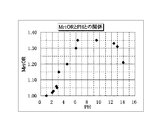
本発明者らは、同一のテクスチャ条件による製造方法により、ガラス基板上に円周状のテクスチャを形成した磁気ディスク用ガラス基板1に対して様々なpHの洗浄液を用いて洗浄を行い、洗浄後に同一の製造条件でシード層2、下地層3、磁性層4、保護層5、潤滑層6を順次形成した磁気ディスクを製造し、洗浄液のpHとMrtORとの相関関係を調査した。結果を図2に示す。
【0058】
ここで洗浄に用いた洗浄液は、PHが7を越える領域はKOH水溶液を希釈することによりpHを変化させたものであり、PHが7を下回る領域はHCl水溶液を希釈することによりpHを変化させたものである。
また、洗浄方法は後述の実施例1と同様の洗浄方法である。pH及びMrtORの測定方法は後述する方法と同一である。
【0059】
シード層2は、Cr合金薄膜(膜厚600オングストローム)からなる、第1のシード層2aと、AlRu薄膜(膜厚:300オングストローム)からなる、第2のシード層2bとからなる。なお、このAlRu薄膜はAl:50at%、Ru:50at%の組成比で構成されている。
【0060】
下地層3は、CrW薄膜(膜厚:100オングストローム)であり、Cr:90at%、W:10at%の組成比で構成されている。
【0061】
磁性層4は、CoCrPtB合金からなり、膜厚は、150オングストロームである。この磁性層のCo、Cr、Pt、Bの各含有量は次のとおりである。すなわち、Co:62at%、Cr:20at%、Pt:12at%、B:6at%である。
【0062】
図2より、ガラス基板洗浄における洗浄液のpHと、MrtORとの間には相関関係が認められた。従って、所定のMrtORを得るために、図2の相関関係に基づいて洗浄液のpHを選定しガラス基板の洗浄を行うことで、所定の磁気異方性比を備えるよう磁気ディスク用ガラス基板を製造することができることが判った。
【0063】
次に、図2で得られた相関関係を基に、所定のMrtORが得られる洗浄液のpHを選定して、以下の実施例及び比較例の磁気ディスク用ガラス基板を製造した。
【0064】
【実施例1】
実施例1の磁気ディスク用ガラス基板の製造方法は、
(1)粗ラッピング工程(粗研削工程)、(2)形状加工工程、(3)精ラッピング工程(精研削工程)、(4)端面鏡面加工工程、(5)第1研磨工程、(6)第2研磨工程、(7)化学強化工程、(8)テクスチャ工程、(9)精密洗浄工程、をこの順で含む。
実施例1では図2の相関関係に基づいてMrtOR=1.33が得られるよう、(9)精密洗浄工程の洗浄液のpHは12.4に選定した。
【0065】
(1)粗ラッピング工程
まず、溶融ガラスから上型、下型、胴型を用いたダイレクトプレスにより直径66mmφ、厚さ1.5mmの円盤状のアルミノシリケートガラスからなるガラス基板を得た。なお、この場合、ダイレクトプレス以外に、ダウンドロー法やフロート法で形成したシートガラスから研削砥石で切り出して円盤状のガラス基板を得てもよい。
アルミノシリケートガラスはSiO2:63.6量%、Al2O3:14.2重量%、Na2O:10.4重量%、Li2O:5.4重量%、ZrO2:6.0重量%、Sb2O3:0.4重量%の組成を有するアルミノシリケートガラスである。
【0066】
次いで、ガラス基板に寸法精度及び形状精度を向上させるためラッピング工程を行った。このラッピング工程は両面ラッピング装置を用い、粒度#400の砥粒を用いて行なった。具体的には、はじめに粒度#400のアルミナ砥粒を用い、荷重を100kg程度に設定して、サンギアとインターナルギアを回転させることによって、キャリア内に収納したガラス基板の両面を面精度0〜1μm、表面粗さ(Rmax)6μm程度にラッピングした。
【0067】
(2)形状加工工程
次に、円筒状の砥石を用いてガラス基板の中央部分に孔を空けると共に、外周端面の研削をして直径を65mmφとした後、外周端面および内周端面に所定の面取り加工を施した。このときのガラス基板端面の表面粗さは、Rmaxで4μm程度であった。
なお、一般に、2.5インチ型HDD(ハードディスクドライブ)では、外径が65mmの磁気ディスクを用いる。
【0068】
(3)精ラッピング工程
次に、砥粒の粒度を#1000に変え、ガラス基板表面をラッピングすることにより、表面粗さをRmaxで2μm程度、Raで0.2μm程度とした。上記ラッピング工程を終えたガラス基板を、中性洗剤、水の各洗浄槽(超音波印加)に順次浸漬して、超音波洗浄を行なった。
【0069】
(4)端面鏡面加工工程
次いで、ブラシ研磨により、ガラス基板を回転させながらガラス基板の端面(内周、外周)の表面の粗さを、Rmaxで1μm、Raで0.3μm程度に研磨した。そして、上記端面鏡面加工を終えたガラス基板の表面を水洗浄した。
【0070】
(5)第1研磨工程
次に、上述したラッピング工程で残留した傷や歪みの除去するため第1研磨工程を両面研磨装置を用いて行なった。両面研磨装置においては、研磨パッドが貼り付けられた上下上盤の間にキャリアにより保持したガラス基板を密着させ、このキャリアをサンギアとインターナルギアとに噛合させ、上記ガラス基板を上下定番によって挟圧する。その後、研磨パッドとガラス基板の研磨面との間に研磨液を供給して回転させることによって、ガラス基板が定盤上で自転しながら公転して両面を同時に研磨加工するものである。以下、実施例で使用する両面研磨装置としては同一装置を用いた。
【0071】
具体的には、ポリシャとして硬質ポリシャ(硬質発泡ウレタン)を用い、研磨工程を実施した。研磨条件は、研磨液として酸化セリウム(平均粒径1.3μm)とし、荷重:100g/cm2、研磨時間:15分とした。上記第1研磨工程を終えたガラス基板を、中性洗剤、純水、純水、IPA、IPA(蒸気乾燥)の各洗浄槽に順次浸漬して、超音波洗浄し、乾燥した。
【0072】
(6)第2研磨工程
次に第1研磨工程で使用したものと同じタイプの両面研磨装置を用い、ポリシャを軟質ポリシャ(スウェードパット)に変えて、第2研磨工程を実施した。この第2研磨工程は、上述した第1研磨工程で得られた平坦な表面を維持しつつ、例えば表面粗さRaを1.0〜0.3μm程度以下まで低減させることを目的とするものである。研磨条件は、研磨液として酸化セリウム(平均粒径0.8μm)とし、荷重:100g/cm2、研磨時間を5分とした。
上記第2研磨工程を終えたガラス基板を、中性洗剤、純水、純水、IPA、IPA(蒸気乾燥)の各洗浄槽に順次浸漬して、超音波洗浄し、乾燥した。
【0073】
(7)化学強化工程
上記洗浄を終えたガラス基板に、ガラス基板表面の圧縮応力値を所定の数値とするために、以下条件で低温型イオン交換法による化学強化工程を施した。化学強化は硝酸カリウム(60%)と硝酸ナトリウム(40%)の混合した化学強化溶融塩を用意し、この化学強化溶融塩を380℃に加熱し、上記洗浄・乾燥済みのガラス基板を240分間浸漬して化学強化処理を行なった。化学強化を終えたガラス基板を硫酸、中性洗剤、純水、純水、IPA、IPA(蒸気乾燥)の各洗浄槽に順次浸漬して、超音波洗浄し、乾燥した。
【0074】
次に、上記洗浄を終えたガラス基板表面の目視検査及び光の反射・散乱・透過を利用した精密検査を実施した。
その結果、ガラス基板表面に付着物による突起や、傷等の欠陥は発見されなかった。
また、上記工程を経て得られたガラス基板の主表面の表面粗さを原子間力顕微鏡(AFM)にて測定したところ、Rmax=2.13nm、Ra=0.20nmと超平滑な表面を持つ磁気ディスク用ガラス基板を得た
また、ガラス基板の外径は65mm、内径は20mm、板圧は0.635mmであった。
【0075】
(8)テクスチャ工程
テープ(Tape)式のテクスチャ装置を用いて、研磨、及び円周状テクスチャ処理を施した。テープには織物タイプのテープを、硬質研磨剤には平均粒径0.125μmの多結晶ダイヤモンドが分散剤・湿潤剤(グリセリン)に溶かしてあるスラリーを用いて行った。
また、その他のテクスチャ装置の加工条件は、
・加工加重 1.4kg
・加工圧力 12g/mm2
・基板回転数 1000rpm
・テープの送り速度 2mm/sec
・加工時間 30sec
とした。
【0076】
このテクスチャ工程の後に、ダイヤモンドスラリーと分散剤(湿潤剤)を洗い流すため、超純水(RO水)シャワーによる前洗を5秒間行った。
得られた磁気ディスク用ガラス基板表面をAFMで高精細に測定した。測定条件は以下の通りである。
測定領域:1μm×1μm
サンプリングモード:256×256
測定形状の波長帯域:3.9nm〜1000nm
カンチレバー(探針):先端曲率半径10nm
【0077】
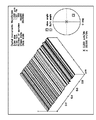
AFM測定の結果、磁気ディスク用ガラス基板表面には、円周状のテクスチャが形成されていた。なお、日本工業規格(JIS)B0601規定による表面特性値については、Rmax=2.20nm、Ra=0.25nmであった。
また、円周方向表面粗さRa(c)に対する半径方向の表面粗さRa(r)の比は6.25であった。
なお、AFMで測定したガラス基板表面の鳥瞰図を図4に掲げる。
【0078】
(9)精密洗浄工程
次に、ガラス基板の精密洗浄を行った。これは、ヘッドクラッシュやサーマルアスペリティ障害の原因となる研磨剤残渣や外来の鉄系コンタミなどを除去し、表面が平滑、清浄なガラス基板を得るためのものである。
【0079】
精密洗浄工程は以下の順で一連の洗浄工程を含む。
まず、以下のようにして洗浄液による洗浄工程を実施した。
KOHとNaOHを100:100に混合した薬液を超純水(DI水)で希釈し、洗浄能力を高めるために非イオン界面活性剤を添加した洗浄液を用いた。
洗浄液のpHは、DI水による希釈により12.4となるよう調整した。
pHはpH計で測定した。
ガラス基板をこの洗浄液に浸漬させた上で揺動させ、2分間洗浄した。このとき洗浄液の温度は50℃とし、超音波を加えて洗浄効果を高めた。
【0080】
次に、水リンス洗浄工程を2分間行なった。これは前述の洗浄で用いた洗浄液の残渣を除去するためのものである。
次に、IPA(イソプロピルアルコール)洗浄工程を2分間行った。これはガラス基板を洗浄するとともに、基板上の水を除去するためのものである。
最後に、IPA(イソプロピルアルコール)蒸気乾燥工程を2分間行った。これは基板に付着している液状IPAをIPA蒸気により除去しつつ乾燥させるためのものである。
【0081】
この精密洗浄工程の後に、前述の同一の測定条件によりガラス基板表面をAFMにて測定した。
結果、Rmax=2.25nm、Ra=0.26nmであった。
また、円周方向表面粗さRa(c)に対する半径方向の表面粗さRa(r)の比は5.52であった。
なお,円周状テクスチャについてはRmaxを5.0nm以下とすることが望ましい、Rmaxを5.0nm以下とすることにより、タッチダウンハイトを5nm以下とすることができる。
【0082】
次に、上記洗浄を終えたガラス基板表面の目視検査及び光の反射・散乱・透過を利用した精密検査を実施した。
その結果、ガラス基板表面に付着物による突起や、傷等の欠陥は発見されなかった。
サーマルアスペリティーやヘッドクラッシュの原因となる異物も発見されなかった。
【0083】
以上の磁気ディスク用ガラス基板の製造方法によって得られたガラス基板に対して、枚葉式スパッタリング装置を用いて、シード層2、下地層3、磁性層4、保護層5を、Arガスによるスパッタリング法で順次形成した。
【0084】
シード層2は、Cr合金薄膜(膜厚600オングストローム)からなる、第1のシード層2aと、AlRu薄膜(膜厚:300オングストローム)からなる、第2のシード層2bとからなる。なお、このAlRu薄膜はAl:50at%、Ru:50at%の組成比で構成されている。
【0085】
下地層3は、CrW薄膜(膜厚:100オングストローム)で、磁性層の結晶構造を良好にするために設けられている。なお、このCrW薄膜は、Cr:90at%、W:10at%の組成比で構成されている。また、結晶粒子の微細化を促進するために、ArガスとCO2ガスとの混合ガス雰囲気中で成膜した。このときArガスに対するCO2ガスとの混合比は0.75%とした。
【0086】
磁性層4は、CoCrPtB合金からなり、膜厚は、150オングストロームである。この磁性層のCo、Cr、Pt、Bの各含有量は次のとおりである。すなわち、Co:62at%、Cr:20at%、Pt:12at%、B:6at%である
【0087】
保護層5は、磁性層が磁気ヘッドとの接触によって劣化することを防止するためのものであり、膜厚50オングストロームの水素化カーボンからなる。
保護層5まで成膜した磁気ディスクに対して、次のようにして潤滑層6を形成した。
潤滑層6は、パーフルオロポリエーテルの液体潤滑剤をディップ法により形成した。
潤滑層の膜厚は9オングストロームである。
【0088】
次に、得られた磁気ディスクを以下のようにして評価した。
(磁気特性評価)
磁気特性は、VSM(振動試料型磁化測定法)により測定した。磁気ディスクから8mm直径の円形試料を切り出し、基板の円周方向、基板の半径方向にそれぞれ外部磁場を印加し(±10kOe)て磁化曲線を求め、Mrt(残留磁化膜厚積)を算出した。
結果は表1に掲げる。MrtORは1.33であった。
【0089】
(信頼性評価)
得られた磁気記録媒体について、グライド特性評価を行ったところ、タッチダウンハイトは、4.2nmであった。通常、40Gbit/in2以上の記録密度が求められるHDDでは、タッチダウンハイトは5nm以下であることが求められる。
【0090】
またLUL耐久性試験について試験したところ、60万回のLUL連続試験に耐久し障害は発生しなかった。また、この間、ヘッドクラッシュや、サーマルアスペリティなどの故障は発生しなかった。通常に使用されるHDDの使用環境では、LUL回数が60万回を越えるには10年間程度の使用が必要とされている。実施例1では、高い信頼性をもつ耐久性の高い磁気ディスクを得ることができた。
【0091】
【実施例2及び実施例3】
次に、実施例2及び実施例3の製造方法により磁気ディスクを製造した。
このとき、図2に基づき、(9)精密洗浄工程において、MrtOR=1.31が得られるよう、洗浄液を用いた洗浄工程における洗浄液のpHを13(実施例2)、MrtOR=1.21となるようpHを14(実施例3)と選定した。
この点以外は実施例1と同一製造条件による製造方法である。なお洗浄液のpHはDI水による希釈量により調節した。
【0092】
精密洗浄工程の後に、前述の同一の測定条件によりガラス基板表面をAFMにて測定した。
結果、実施例2では、Rmax=2.22nm、Ra=0.25nmであった。
また、円周方向表面粗さRa(c)に対する半径方向の表面粗さRa(r)の比は4.10であった。
MrtORは1.31であった。
【0093】
結果、実施例3では、Rmax=2.31nm、Ra=0.22nmであった。
また、円周方向表面粗さRa(c)に対する半径方向の表面粗さRa(r)の比は2.29であった。
MrtORは1.21であった。
グライド特性、LUL特性は実施例2、実施例3ともに、実施例1と同様に良好な結果が得られ、また、ヘッドクラッシュやサーマルアスペリティ障害も発生しなかった。
【0094】
【実施例4】
次に、実施例4の製造方法により磁気ディスクを製造した。
実施例4は、実施例1の(9)精密洗浄工程における洗浄液を用いた洗浄工程について、洗浄液をDI水のみとした以外は、実施例1と同一製造条件による製造方法である。DI水のpHは6.3であった。図2記載の相関関係に基づくと、pH=6.3の洗浄液を用いた場合、MrtORは1.35が得られている。
【0095】
精密洗浄工程の後に、前述の同一の測定条件によりガラス基板表面をAFMにて測定した。
結果、Rmax=3.11nm、Ra=0.30nmであった。
また、円周方向表面粗さRa(c)に対する半径方向の表面粗さRa(r)の比は6.23であった。
MrtORは1.35であった。
【0096】
LUL特性は実施例1と同様に良好な結果が得られたが、タッチダウンハイトは5.0nmとなり、グライド特性は実施例1に比べて大きくなった。
従って、洗浄液をDI水など超純水とする場合、高いMrtORを得ることができるが、グライド特性が悪化する場合があるので、ジェット水流による洗浄、スピン洗浄、スクラブ洗浄など物理的エネルギーを付加する洗浄手段を併用することが好ましいと言える。
【0097】
なお、本実施例において、洗浄液をDI水のみとした上記洗浄液を用いた洗浄の後に、スクラブ洗浄を行ったところ、タッチダウンハイトは4.8nmとなり、グライド特性を改善することができた。
【0098】
【実施例5】
次に、実施例5の製造方法により磁気ディスクを製造した。
このとき、図2に基づいてMrtOR=1.20が得られるよう、(9)精密洗浄工程における洗浄液を用いた洗浄工程における洗浄液のpHを4.5と選定した。
洗浄液は硫酸を用い、pH=4.5となるようにDI水で希釈した。
この時の硫酸の濃度は1.6×10⁻⁵mol/lである。
この点以外は実施例1と同一製造条件による製造方法である。
【0099】
精密洗浄工程の後に、前述の同一の測定条件によりガラス基板表面をAFMにて測定した。
結果、Rmax=2.33nm、Ra=0.23nmであった。
また、円周方向表面粗さRa(c)に対する半径方向の表面粗さRa(r)の比は2.13であった。
MrtORは1.20であった。
グライド特性、LUL特性は実施例1と同様に良好な結果が得られ、また、ヘッドクラッシュやサーマルアスペリティ障害も発生しなかった。
【0100】
【比較例1及び比較例2】
次に比較例1及び比較例2の磁気ディスクを製造した。
比較例1では、(9)精密洗浄工程において、洗浄液を用いた洗浄工程にける洗浄液のpHを2.0と選定した。比較例2では、pHを1.0と選定した。
図2の相関関係に基づけば、ph=2.0の洗浄液を用いた場合、MrtOR=1.02である。
また、洗浄液のpHが1.0の場合、MrtORは1である。
比較例1では、洗浄液としてDI水で希釈した硫酸を用いた。洗浄液中の硫酸の濃度は6.7×10⁻³mol/lである。
比較例2では、洗浄液としてDI水で希釈した塩酸を用いた。洗浄液中の塩酸の濃度は1.0×10⁻¹mol/lである。
この点以外は実施例1と同一製造条件による製造方法である。
【0101】
精密洗浄工程の後に、前述の実施例1と同一の測定条件によりガラス基板表面をAFMにて測定したところ、比較例1においては、
結果、Rmax=2.35nm、Ra=0.24nmであった。
また、円周方向表面粗さRa(c)に対する半径方向の表面粗さRa(r)の比は1.22であった。
MrtORは1.02であった。
AFMで測定した、比較例1のガラス基板表面の鳥瞰図を図5に掲げる。
【0102】
比較例2においては、Rmax=2.38nm、Ra=0.24nmであった。
また、円周方向表面粗さRa(c)に対する半径方向の表面粗さRa(r)の比は1.15であった。
MrtORは1.00であった。
グライド特性、LUL特性は、比較例1及び比較例2の磁気ディスク共に、実施例1と同様に良好な結果が得られ、また、ヘッドクラッシュやサーマルアスペリティ障害も発生しなかった。
【0103】
図3の表1において、実施例1〜実施例5及び、比較例1〜比較例2の結果を対比すると、ガラス基板上に磁性層に磁気異方性を付与するテクスチャを形成した後に、磁性層を形成するまでの間の洗浄工程において洗浄液のpHを4.5〜14と選定することにより、1.2以上の高いMrtORを得られるようになり、このpHの領域以外の洗浄液を用いた場合、高いMrtORは得られないことが判る。これは、洗浄液によるリーチング作用及びエッチング作用により、MrtORに寄与するガラス基板表面上の前記テクスチャの微細形状が乱されてしまうことによるものと考えられる。図4(実施例1)のガラス基板表面形状と図5(比較例1)のガラス基板表面状態とを対比すると、前記テクスチャの微細形状が乱されていることが判る。
【0104】
なお、実施例1〜実施例5及び比較例1〜比較例2の各々の磁気ディスク製造工程において、(9)精密洗浄工程における洗浄液を用いた洗浄工程と同様のpHを備える保管液で前記テクスチャが形成された磁気ディスク用ガラス基板を1時間保管したところ、実施例1〜実施例5及び比較例1〜比較例2と同様の結果が得られた。
【0105】
【実施例6及び実施例7】
次に、アルミノシリケートガラスとして、SiO2を65.5重量%、Al2O3を17.7重量%、Li2Oを3.3重量%、Na2Oを7.9重量%、K2Oを0.3重量%、MgOを1.7重量%、CaOを3.6重量%含有するガラスを用いたガラス基板とした(実施例6)。また、ソーダライムガラスとして、SiO2を72.5重量%、Na2Oを15.0重量%、Al2O3を1.0重量%、CaOを9.0重量%、MgOを2.5重量%含有するガラスを用いたガラス基板とした(実施例7)。ガラスの組成以外の点においては、実施例1と同様の製造方法による。
【0106】
実施例6においては、Ra(r)/Ra(c)が4.02、MrtORは1.30が得られた。実施例1には劣るが、好適な結果が得られた。
実施例7においては、Ra(r)/Ra(c)が2.11、MrtORは1.21が得られた。実施例1、実施例6にはには劣るが好適な結果が得られた。実施例1と実施例7の結果を対比すると、本発明においてガラス基板に用いる硝種としては、アルミノシリケートガラスの方が好適であることが判る。
【0107】
【発明の効果】
本発明によれば、ガラス基板上に少なくとも磁性層を形成したときに、磁性層に高い磁気異方性を付与することのできるガラス基板を提供することができる。
本発明によれば、ガラス基板上に少なくとも磁性層を形成したときに、磁性層に所望の磁気異方性を付与することのできるガラス基板を提供することができる。
【0108】
本発明によれば、高い磁気異方性を備え、耐衝撃性に優れた磁気ディスクを廉価に提供することができる。
本発明によれば、所望の磁気異方性を備え、耐衝撃性に優れた磁気ディスクを廉価に提供することができる。
【図面の簡単な説明】
【図1】実施の形態による磁気ディスクの層構成を模式的に示す断面図である。
【図2】MrtORとpHとの相関関係を示す図である。
【図3】実施例と比較例の結果を示す表1である。
【図4】実施例1に係る磁気ディスク用ガラス基板の表面をAFMにより測定した結果である。
【図5】比較例1に係る磁気ディスク用ガラス基板の表面をAFMにより測定した結果である。
【符号の説明】
1 磁気ディスク用ガラス基板
2 シード層
3 下地層
4 磁性層
5 保護層
6 潤滑層
10 磁気ディスク[0001]
TECHNICAL FIELD OF THE INVENTION
The present invention relates to a magnetic recording medium, and more particularly, to a magnetic disk mounted on an HDD (hard disk drive) or the like.
[0002]
[Prior art]
2. Description of the Related Art Today, information recording technology, particularly magnetic recording technology, is required to undergo dramatic technological innovation with the rapid development of the IT industry. For a magnetic disk mounted on an HDD or the like, a technology capable of realizing an information recording density of 40 Gbit / in2 to 100 Gbit / in2 or more has been demanded due to a demand for high capacity.
[0003]
A magnetic disk is required to have particularly excellent magnetic characteristics in the flying flight direction of a magnetic recording head. For this reason, for example, in Japanese Patent Application Laid-Open No. 62-273819, a magnetic layer is formed on a metal substrate surface of an aluminum alloy or the like by forming a texture for imparting magnetic anisotropy, and then a magnetic layer is formed. Compared to the characteristics, the magnetic characteristics of the magnetic recording head in the flying flight direction have been improved.
[0004]
By the way, in recent years, due to demands for mobile and miniaturized HDDs, glass substrates that have high rigidity, excellent impact resistance, and high surface smoothness have been receiving attention.
Further, in the case of a glass substrate, since it is excellent in impact resistance, there is no need to apply a metal film such as NiP to reinforce the rigidity as in the case of an aluminum alloy substrate, and the process can be shortened. There is an advantage that a compact magnetic disk can be provided, and miniaturization is easy. For example, the present applicant discloses in JP-A-2002-32909 a magnetic recording medium in which a circumferential texture is formed on a glass substrate and a magnetic layer or the like is sputtered thereon.
[0005]
[Problems to be solved by the invention]
Even in the case of a glass substrate, it is desired that the magnetic properties in the circumferential direction be superior to the magnetic properties in the radial direction. For example, when achieving a recording density of 40 Gbit / inch2 or more, the magnetic anisotropy ratio (MrtOR) based on the product of the residual magnetization film thickness is required to be 1.2 or more. Further, in order to obtain a recording density of 50 Gbit / inch2 or more, it is considered that MrtOR is preferably 1.3 or more, and particularly, MrtOR is preferably 1.35 or more in a high recording density region of 60 Gbit / inch2 or more.
[0006]
The above-mentioned MrtOR is a magnetic anisotropy ratio OR (Oriented Ratio) calculated from the product of the residual magnetization film thickness (Mrt). At any point on the main surface of the magnetic recording medium, when the product of the thickness of the residual magnetization in the circumferential direction is Mrt (c) and the product of the thickness of the residual magnetization in the radial direction is Mrt (r), the relationship to Mrt (r) is obtained. The ratio Mrt (c) / Mrt (r) of Mrt (c) is defined as MrtOR.
[0007]
Here, Mrt is a product of Mr (residual magnetization) and t (magnetic layer thickness of the medium). If MrtOR is substantially 1, the magnetic recording medium is an isotropic magnetic recording medium having substantially equal magnetic properties in the circumferential direction and the radial direction. It shows that the magnetic anisotropy in the circumferential direction is improved as the value of MrtOR exceeds 1 and increases.
[0008]
However, unlike the case where a texture giving magnetic anisotropy is formed on a metal surface, such as an aluminum alloy substrate or a substrate on which a metal film such as NiP is applied, a magnetic anisotropic layer is directly formed on a glass substrate surface. In the case where a texture for imparting the property is formed and a magnetic layer is formed thereon, only about 1.0 to 1.1 is obtained for MrtOR, which is a factor that hinders the increase in capacity and cost of HDD. Had become.
[0009]
The present invention has been made in view of the above-described problems, and even when a glass substrate is used, a MrtOR of 1.2 or more is obtained, and a recording density of 40 Gbit / in2 or more can be achieved. An object of the present invention is to provide an excellent and inexpensive method for manufacturing a glass substrate for a magnetic disk.
[0010]
Further, even when a glass substrate is used, a method for manufacturing a low-cost magnetic disk excellent in impact resistance, capable of achieving a MrtOR of 1.2 or more and achieving a recording density of 40 Gbit / in2 or more is provided. The purpose is to:
[0011]
[Means for Solving the Problems]
(Configuration 1)
A texture step of forming a texture for imparting magnetic anisotropy to the magnetic layer on the main surface of the glass substrate, and after the texturing step, a method of manufacturing a glass substrate for a magnetic disk including a glass substrate cleaning step,
The method of manufacturing a glass substrate for a magnetic disk, wherein the cleaning step includes cleaning a texture of the glass substrate with a treatment liquid having a pH of 4.5 to 14.
[0012]
(Configuration 2)
A method for manufacturing a glass substrate for a magnetic disk according to Configuration 1, comprising:
Before cleaning the texture of the glass substrate with the processing liquid,
A method of manufacturing a glass substrate for a magnetic disk, comprising a step of removing abrasive grains attached to a glass substrate in the texturing step.
[0013]
(Configuration 3)
A method for manufacturing a glass substrate for a magnetic disk according to
A method for manufacturing a glass substrate for a magnetic disk, wherein the glass constituting the glass substrate is aluminosilicate glass.
[0014]
(Configuration 4)
A method for manufacturing a glass substrate for a magnetic disk according to Configuration 3, wherein:
The aluminosilicate glass is a glass containing SiO2 at 58 to 75% by weight, Al2O3 at 5 to 23% by weight, Li2O at 3 to 10% by weight, Na2O at 4 to 13% by weight as a main component. Of manufacturing a glass substrate for a magnetic disk.
[0015]
(Configuration 5)
5. The method for manufacturing a glass substrate for a magnetic disk according to any one of the constitutions 1 to 4, wherein at least a magnetic layer is formed on the glass substrate, wherein the magnetic layer has a remanence film thickness product of 1.2 or more. A method of manufacturing a glass substrate for a magnetic disk manufactured so as to impart magnetic anisotropy.
[0016]
(Configuration 6)
A method for manufacturing a magnetic disk, wherein at least a magnetic layer is formed on a glass substrate manufactured by the method for manufacturing a glass substrate for a magnetic disk according to any one of Configurations 1 to 5.
[0017]
(Configuration 7)
A method for manufacturing a magnetic disk according to
A method for manufacturing a magnetic disk, wherein a processing solution in a process of completely cleaning the glass substrate from the formation of the texture on the glass substrate to the formation of the magnetic layer is a processing solution having a pH of 4.5 to 14. .
[0018]
(Configuration 8)
When a glass substrate having a texture on its main surface that imparts magnetic anisotropy to the magnetic layer when at least the magnetic layer is formed on the glass substrate is treated with a processing liquid, at least a magnetic anisotropic magnetic disk that forms the magnetic layer In the manufacturing method,
In advance, the correlation between the pH of the processing solution and the magnetic anisotropy is determined,
In order to obtain a predetermined magnetic anisotropy, the pH of the processing solution is selected based on the correlation,
A method of manufacturing a magnetic anisotropic magnetic disk, comprising processing a glass substrate according to the selection conditions.
[0019]
The present inventors have studied from various viewpoints the reason why a high MrtOR cannot be obtained when a texture giving magnetic anisotropy is directly formed on a magnetic layer on a glass substrate for a magnetic disk.
[0020]
Conventionally, in a step of cleaning a glass substrate for a magnetic disk, a strong acidic cleaning liquid has been often used in order to obtain high cleaning performance. Examples of the strong acidic cleaning solution include sulfuric acid, hydrofluoric acid, silicic hydrofluoric acid, and the like. By obtaining a high cleaning ability due to the strong acidity, foreign substances that cause head crash, thermal asperity, and the like are removed from the glass substrate.
[0021]
However, according to the knowledge obtained by the inventors of the present application, in the case of the glass substrate on which the texture is formed, if the conventional glass substrate cleaning step focusing on the cleaning ability is used, a high magnetic anisotropy is obtained. It became clear that it became a hindrance factor for the purpose of obtaining.
[0022]
According to the facts clarified by the present inventors, MrtOR is determined by the pH of the treatment liquid in the glass substrate cleaning step provided between the formation of the texture on the glass substrate and the formation of the magnetic layer. It was found to fluctuate.
[0023]
The treatment liquid in the glass substrate cleaning step referred to here is a cleaning liquid in the glass substrate cleaning step, a storage liquid in the glass substrate storage step, a storage liquid in the glass substrate transfer step, and the like, which cleans the glass substrate on which the texture is formed. It is a processing liquid having an action to perform. It has been found that in a glass substrate having the texture formed on the main surface of the glass substrate, the treatment liquid requires strict control of the PH so as not to lower the magnetic anisotropy.
[0024]
Specifically, it has been found that when the pH of the treatment liquid is selected to be 4.5 to 14, a high MrtOR can be obtained. In this case, a high MrtOR of 1.2 or more can be obtained, which is preferable. Further, it is particularly preferable that the pH of the treatment liquid is selected to be 6.3 to 13. In this case, a high MrtOR of 1.3 or more can be obtained.
[0025]
From the viewpoint of the present inventors, the reason why such a phenomenon occurs is considered as follows. Generally, when a glass containing a positive ion (cation) such as an alkali metal ion is brought into contact with a liquid, hydrogen ions (H +) contained in the liquid act as a leaching action on the glass. Is replaced by a hydrogen ion (H +).
[0026]
Due to this leaching action, alkali metal ions having a relatively large ionic radius of the glass substrate are replaced by hydrogen ions having a relatively small ionic radius contained in the liquid, so that the surface of the glass substrate is attacked, It is considered that the fine texture shape for imparting magnetic anisotropy to the magnetic layer formed on the surface is disturbed. Therefore, it is considered preferable that the liquid that comes into contact with the glass substrate after the texturing step does not act as a leaching function of reducing the magnetic anisotropy with respect to the glass substrate.
[0027]
Conventionally, in the glass substrate for magnetic disks, the disorder of the glass substrate surface shape due to the leaching action was not considered a problem because the turbulence of the glass substrate surface due to the leaching action was extremely small, which affected the flying characteristics of the magnetic recording head. It is considered that this was because no thermal asperity failure was caused.
[0028]
The concentration of the hydrogen ion (H +) contained in the liquid can be quantified by the pH, but the reason why a high MrtOR can be obtained by setting the pH of the treatment liquid to 4.5 or more is that the pH is 4.5 or more. It is considered that the leaching action can be suppressed.
[0029]
Next, the relationship between the glass substrate and the hydroxyl ion (OH-) contained in the liquid will be considered. Hydroxide ions are considered to have an etching action that erodes the covalent bond of Si—O, which is the basic skeleton of glass. Therefore, if the hydroxyl ions become excessive, the magnetic layer formed on the glass substrate surface becomes magnetically anisotropic. It is considered that the fine texture shape for imparting the texture is disturbed. Therefore, it is considered preferable that the liquid that comes into contact with the glass substrate after the texturing step does not act on the glass substrate to perform an etching action for reducing magnetic anisotropy.
[0030]
Conventionally, in the glass substrate for magnetic disks, the irregularity of the glass substrate surface shape due to the etching action of hydroxyl ions has not been a problem because the irregularity of the glass substrate surface is extremely small, which affects the flying characteristics of the magnetic recording head. It is considered that this was because no thermal asperity failure was caused.
[0031]
The concentration of the hydroxyl group ion (OH-) contained in the liquid can be quantified by pH. The reason why a high MrtOR can be obtained by setting the pH of the treatment liquid to 13 or less is that when the pH is 13 or less, It is considered that the etching action by ions can be suppressed.
[0032]
It is preferable that the pH of the treatment liquid be closer to neutral since the leaching action and the etching action on the glass substrate are suppressed.
However, in the case of the cleaning liquid in the cleaning step, the cleaning performance is simultaneously lowered, so that the pH of the cleaning liquid is preferably adjusted appropriately within the above range so as to obtain a suitable cleaning performance.
[0033]
In the case of the cleaning process, if the pH of the cleaning solution approaches neutrality, the cleaning performance will decrease.In this case, to compensate for the cleaning performance, add physical energy such as cleaning with a jet stream, spin cleaning, and scrub cleaning. It is preferable to use a washing means for cleaning. When water is used as the cleaning liquid or when the cleaning liquid is diluted with water, it is preferable to use water that has been subjected to measures against foreign substances such as ultrapure water (DI water and RO water) and measures against residual ions. By performing such cleaning, a high magnetic anisotropy ratio can be obtained while preventing head crash and thermal asperity.
[0034]
In order to suitably suppress head crash and thermal asperity, and to obtain a high magnetic anisotropy ratio, remove the abrasive adhered to the glass substrate in the above-described texture process before cleaning the texture of the glass substrate with the processing liquid. It is preferable to include a step of performing
[0035]
An abrasive used for forming the texture on the glass substrate (including abrasive grains made of diamond or the like and a wetting agent made of glycerin or the like) may cause head crash or thermal asperity. Therefore, it is preferable to remove the abrasive before cleaning the texture of the glass substrate with the treatment liquid, since the effect of the cleaning step can be enhanced.
[0036]
Before the cleaning step with the cleaning liquid, if a step of removing the abrasive adhered to the glass substrate in the texturing step is provided, the pH of the cleaning liquid can be made closer to neutral, so that a high magnetic anisotropy ratio can be obtained. It is particularly preferred.
[0037]
The step of removing the abrasive attached to the glass substrate includes a step of shower-cleaning the glass substrate after the texturing step with ultrapure water (RO water, DI water) to remove the abrasive.
[0038]
As the washing step using a washing solution, the washing solution is preferably an aqueous KOH solution, an aqueous NaOH solution, an aqueous sodium phosphate solution, or the like. When a cleaning solution containing KOH is used as the cleaning solution, it is preferable that the KOH content be 8% by weight or less, since the cleaning performance is high. Among them, those containing both KOH and NaOH are particularly preferable because they are excellent in removing particles on the glass substrate, oils and fats, metal ions, and abrasives. In this case, if the ratio between the contents of KOH and NaOH is adjusted in the range of 60:40 to 40:60 by volume%, the cleaning performance is high and suitable. In the case where diamond abrasive grains or free abrasive grains containing a wetting agent such as glycerin are used in the step of forming the texture on the glass substrate, the removal ability of these abrasive grains increases, which is preferable.
[0039]
The temperature of the cleaning liquid in the cleaning step is preferably 20 ° C to 60 ° C for practical use. If the temperature is lower than 20 ° C., the cleaning ability is low, and there is a possibility that a trouble such as a head crash or thermal asperity may occur when the magnetic recording head runs on the magnetic disk. On the other hand, if the temperature exceeds 60 ° C., drying occurs on the glass surface, which is not preferable.
[0040]
The cleaning time may be within a range that does not disturb the surface shape of the glass substrate. However, if the cleaning time is not more than 10 seconds, the cleaning effect is insufficient, and if it exceeds 1 hour, the productivity is reduced and the manufacturing cost is reduced. It is not preferable because it increases.
[0041]
In the cleaning step of the present invention, it is preferable to add ultrasonic waves. By applying ultrasonic waves, a high cleaning effect can be obtained, so that failures such as head crash and thermal asperity can be prevented.
[0042]
The glass constituting the glass substrate used in the present invention is preferably aluminosilicate glass. If the aluminosilicate glass is within the above-mentioned pH range, the leaching action and the etching action can be strictly controlled, so that a high MrtOR can be obtained.
[0043]
As the aluminosilicate glass, a glass containing an alkali metal element is preferable. A glass substrate containing an alkali element is suitable for chemical strengthening and can obtain excellent LUL characteristics and impact resistance. In the present invention, since the leaching function is suppressed, a high MrtOR can be obtained even with a glass substrate containing an alkali element, which is preferable.
[0044]
In particular, among the aluminosilicate glasses, the composition ratio is mainly composed of SiO2: 58 to 75% by weight, Al2O3: 5 to 23% by weight, Li2O: 3 to 10% by weight, and Na2O: 4 to 13% by weight. It is preferable that the glass is contained.
[0045]
Further, the composition of the glass substrate is as follows: SiO2: 62 to 75% by weight, Al2O3: 5 to 15% by weight, Li2O: 4 to 10% by weight, Na2O: 4 to 12% by weight, ZrO2: 5.5 to 15% by weight. It is preferable to use an aluminosilicate glass containing Na as a main component, a weight ratio of Na2O / ZrO2 of 0.5 to 2.0, and a weight ratio of Al2O3 / ZrO2 of 0.4 to 2.5.
[0046]
Further, in order to eliminate projections on the glass substrate surface caused by undissolved ZrO2, SiO2 is 57 to 74%, ZnO2 is 0 to 2.8%, Al2O3 is 3 to 15% in terms of mol%. It is preferable to use glass for chemical strengthening containing 7 to 16% of LiO2 and 4 to 14% of Na2O.
[0047]
Such an aluminosilicate glass, by chemical strengthening, has an increased transverse rupture strength, a deep compressive stress layer, a superior Knoop hardness, and a very good controllability of the leaching action and etching action. Therefore, a high MrtOR can be obtained, which is particularly preferable. Note that a typical example of the above aluminosilicate glass is N5 manufactured by HOYA Corporation.
[0048]
In the present invention, the glass substrate is preferably chemically strengthened. The chemically strengthened glass substrate has a high strength and a high flatness because a stress layer is formed on the surface of the glass substrate, and therefore has excellent LUL characteristics and impact resistance, and is particularly suitable for HDDs for mobile use. is there.
[0049]
Note that this chemical strengthening step is preferably performed before the step of forming the texture on the glass substrate surface. In the chemical strengthening process, a small disturbance occurs in the compressive stress distribution on the surface of the glass substrate in the process of ion exchange, or a chemical strengthening salt binds firmly to the surface of the glass substrate, thereby disturbing the surface roughness of the glass substrate. There are cases. Therefore, when the chemical strengthening step is performed after forming the texture on the glass substrate, the texture shape for imparting magnetic anisotropy to the magnetic layer is disturbed by the chemical strengthening, and a desired MrtOR cannot be obtained. There are cases. Therefore, it is preferable to perform the chemical strengthening step before forming the texture.
[0050]
In the present invention, as a method for manufacturing a magnetic disk, a treatment liquid having a pH of 4.5 to 14 is used in the entire cleaning process of the glass substrate from the formation of the texture on the glass substrate to the formation of the magnetic layer. It is preferable that This is preferable because a magnetic disk having a high MrtOR of 1.2 or higher can be obtained even when the texture is directly formed on the glass substrate.
More preferably, the pH of the treatment liquid is preferably 6.3 to 13.0. This is preferable because a magnetic disk having a high MrtOR of 1.3 or more can be obtained even when the texture is directly formed on the glass substrate.
[0051]
In the present invention, a glass substrate having a texture for giving magnetic anisotropy to a magnetic layer when a magnetic layer is formed on the glass substrate on a main surface is treated with a processing liquid to form at least a magnetic layer for forming a magnetic layer. In the method of manufacturing an isotropic magnetic disk, the correlation between the pH of the processing solution and the magnetic anisotropy is determined in advance, and in order to obtain a predetermined magnetic anisotropy, the processing solution is determined based on the correlation. There is also provided a method for manufacturing a magnetic anisotropic magnetic disk, which comprises selecting a pH and treating a glass substrate in accordance with the selection conditions.
[0052]
By manufacturing the magnetic disk in this manner, a desired magnetic anisotropy ratio (MrtOR) based on the product of the residual magnetization film thickness can be obtained with good reproducibility. The variation in MrtOR can be suppressed and the manufacturing yield can be improved, so that the cost and price of the magnetic disk can be reduced.
[0053]
In the present invention, the composition of the magnetic layer is not particularly limited, but a material made of a Co alloy having an hcp crystal structure is preferable because of its high crystal magnetic anisotropy. Of the Co alloys, a CoPt alloy is preferable because a high coercive force of 3000 Oe or more can be obtained. In the case of a CoCr-based alloy, the exchange interaction between magnetic particles can be suppressed by Cr, so that medium noise can be reduced, which is preferable. Examples of these Co-based alloys include CoCrPt-based alloys, CoCrPtTa-based alloys, CoCrPtTaB-based alloys, CoCrPtB-based alloys, and CoCrPtNb-based alloys, in addition to CoPt alloys and CoCr alloys. Among them, CoCrPtB alloy has low medium noise and is suitable for high recording density. In the case of a CoCrPtB alloy, the preferred range of the Cr content is 13 at% to 25 at%, the preferred content of Pt is 6 at% to 15 at%, the preferred content of B is 2 at% to 10 at%, and the balance is balance. Is preferably Co.
[0054]
In the present invention, the texture formed on the glass substrate and imparting magnetic anisotropy to the magnetic layer may be any form having regularity that can increase the magnetic anisotropy in the flying traveling direction of the magnetic recording head. In the case of a disk, since the running direction of the magnetic recording head is the circumferential direction, a texture having a circumferential regularity, or a cross texture, an elliptical texture, a spiral texture, or a cross texture having a shape component intersecting with the circumferential direction is used. A composite form of these shape components may be used. Among them, the circumferential texture is preferable because it has a high effect of arranging the magnetic particles in the running direction of the magnetic recording head.
[0055]
BEST MODE FOR CARRYING OUT THE INVENTION
FIG. 1 shows a
[0056]
The magnetic disk glass substrate 1 is a glass substrate obtained by polishing, circumferentially textured, and precision-cleaned aluminosilicate glass that has been chemically strengthened. On this glass substrate 1, a
[0057]
The present inventors performed cleaning using a cleaning solution of various pH on the magnetic disk glass substrate 1 having a circumferential texture formed on the glass substrate by a manufacturing method under the same texture conditions, and after cleaning. Under the same manufacturing conditions, a magnetic disk in which a
[0058]
The pH of the cleaning liquid used in the cleaning was changed by diluting the aqueous KOH solution in the region where the pH was higher than 7, and was changed by diluting the aqueous HCl solution in the region where the pH was lower than 7. It is a thing.
The cleaning method is the same as the cleaning method of Example 1 described later. The method for measuring pH and MrtOR is the same as the method described later.
[0059]
The
[0060]
The underlayer 3 is a CrW thin film (thickness: 100 angstroms) and has a composition ratio of Cr: 90 at% and W: 10 at%.
[0061]
The
[0062]
From FIG. 2, a correlation was recognized between the pH of the cleaning solution in cleaning the glass substrate and MrtOR. Accordingly, in order to obtain a predetermined MrtOR, the pH of the cleaning liquid is selected based on the correlation shown in FIG. 2 and the glass substrate is cleaned, thereby manufacturing a glass substrate for a magnetic disk so as to have a predetermined magnetic anisotropy ratio. I found that I could do that.
[0063]
Next, based on the correlation obtained in FIG. 2, the pH of the cleaning solution at which a predetermined MrtOR was obtained was selected, and glass substrates for magnetic disks of the following Examples and Comparative Examples were manufactured.
[0064]
Embodiment 1
The manufacturing method of the glass substrate for a magnetic disk of the first embodiment is as follows.
(1) Rough lapping step (rough grinding step), (2) shape processing step, (3) fine lapping step (fine grinding step), (4) end face mirror polishing step, (5) first polishing step, (6) The second polishing step, (7) chemical strengthening step, (8) texture step, and (9) precision cleaning step are included in this order.
In Example 1, the pH of the cleaning liquid in the (9) precision cleaning step was selected to be 12.4 so that MrtOR = 1.33 was obtained based on the correlation shown in FIG.
[0065]
(1) Rough lapping process
First, a disc-shaped glass substrate made of aluminosilicate glass having a diameter of 66 mm and a thickness of 1.5 mm was obtained from a molten glass by direct pressing using an upper mold, a lower mold, and a body mold. In this case, in addition to the direct press, a disk-shaped glass substrate may be obtained by cutting a sheet glass formed by a down-draw method or a float method with a grinding wheel.
Aluminosilicate glass: SiO2: 63.6% by weight, Al2O3: 14.2% by weight, Na2O: 10.4% by weight, Li2O: 5.4% by weight, ZrO2: 6.0% by weight, Sb2O3: 0.4% by weight % Of aluminosilicate glass.
[0066]
Next, a lapping process was performed on the glass substrate to improve dimensional accuracy and shape accuracy. This lapping step was performed using a double-sided lapping apparatus and abrasive grains having a grain size of # 400. Specifically, first, using alumina abrasive grains having a grain size of # 400, setting the load to about 100 kg, and rotating the sun gear and the internal gear, both surfaces of the glass substrate housed in the carrier have a surface accuracy of 0 to 1 μm. And lapping to a surface roughness (Rmax) of about 6 μm.
[0067]
(2) Shape processing process
Next, a hole was made in the central portion of the glass substrate using a cylindrical grindstone, and the outer peripheral end surface was ground to a diameter of 65 mmφ. Then, the outer peripheral end surface and the inner peripheral end surface were subjected to predetermined chamfering. At this time, the surface roughness of the end face of the glass substrate was about 4 μm in Rmax.
In general, a 2.5-inch HDD (hard disk drive) uses a magnetic disk having an outer diameter of 65 mm.
[0068]
(3) Fine wrapping process
Next, the particle size of the abrasive grains was changed to # 1000, and the surface of the glass substrate was wrapped to make the surface roughness about 2 μm in Rmax and about 0.2 μm in Ra. The glass substrate after the lapping step was sequentially immersed in each of washing tanks (ultrasonic application) of a neutral detergent and water to perform ultrasonic cleaning.
[0069]
(4) Mirror finish process
Next, the surface roughness of the end surface (inner circumference, outer circumference) of the glass substrate was polished to about 1 μm in Rmax and about 0.3 μm in Ra while rotating the glass substrate by brush polishing. Then, the surface of the glass substrate which had been subjected to the end surface mirror finishing was washed with water.
[0070]
(5) First polishing step
Next, a first polishing step was performed using a double-side polishing apparatus in order to remove scratches and distortion remaining in the above-described lapping step. In a double-side polishing apparatus, a glass substrate held by a carrier is brought into close contact between an upper and lower plate to which a polishing pad is attached, and this carrier is meshed with a sun gear and an internal gear, and the glass substrate is clamped by an upper and lower standard. . Then, by supplying a polishing liquid between the polishing pad and the polishing surface of the glass substrate and rotating the glass substrate, the glass substrate revolves while rotating on the surface plate to simultaneously grind both surfaces. Hereinafter, the same apparatus was used as the double-side polishing apparatus used in the examples.
[0071]
Specifically, a polishing step was performed using a hard polisher (hard urethane foam) as the polisher. The polishing conditions were cerium oxide (average particle size: 1.3 μm) as a polishing solution, load: 100 g /
[0072]
(6) Second polishing step
Next, a second polishing step was performed using a double-side polishing apparatus of the same type as that used in the first polishing step, and changing the polisher to a soft polisher (Sweed Pad). The second polishing step aims at reducing, for example, the surface roughness Ra to about 1.0 to 0.3 μm or less while maintaining the flat surface obtained in the first polishing step. is there. The polishing conditions were cerium oxide (average particle size 0.8 μm) as a polishing solution, load: 100 g /
The glass substrate having been subjected to the second polishing step was sequentially immersed in cleaning tanks of a neutral detergent, pure water, pure water, IPA and IPA (steam drying), ultrasonically cleaned, and dried.
[0073]
(7) Chemical strengthening process
The glass substrate after the cleaning was subjected to a chemical strengthening step by a low-temperature ion exchange method under the following conditions in order to set the compressive stress value on the surface of the glass substrate to a predetermined value. For chemical strengthening, prepare a chemically strengthened molten salt in which potassium nitrate (60%) and sodium nitrate (40%) are mixed, heat the chemically strengthened molten salt to 380 ° C., and immerse the washed and dried glass substrate for 240 minutes. Then, a chemical strengthening treatment was performed. The chemically strengthened glass substrate was sequentially immersed in cleaning tanks of sulfuric acid, a neutral detergent, pure water, pure water, IPA, and IPA (steam drying), ultrasonically cleaned, and dried.
[0074]
Next, a visual inspection of the surface of the glass substrate after the cleaning and a precision inspection using reflection, scattering, and transmission of light were performed.
As a result, no defects such as protrusions and scratches were found on the surface of the glass substrate.
When the surface roughness of the main surface of the glass substrate obtained through the above steps was measured by an atomic force microscope (AFM), the glass substrate had an ultra-smooth surface of Rmax = 2.13 nm and Ra = 0.20 nm. Obtained glass substrate for magnetic disk
The outer diameter of the glass substrate was 65 mm, the inner diameter was 20 mm, and the plate pressure was 0.635 mm.
[0075]
(8) Texture process
Polishing and circumferential texture processing were performed using a tape-type texture device. A woven tape was used as the tape, and a slurry in which polycrystalline diamond having an average particle size of 0.125 μm was dissolved in a dispersant / wetting agent (glycerin) was used as the hard abrasive.
In addition, the processing conditions of other texture devices are as follows:
・ Processing weight 1.4kg
・ Processing pressure 12g / mm2
・ Substrate rotation speed 1000rpm
・ Tape feed speed 2mm / sec
・ Processing time 30sec
And
[0076]
After the texturing step, prewashing with a shower of ultrapure water (RO water) was performed for 5 seconds to wash off the diamond slurry and the dispersant (wetting agent).
The surface of the obtained glass substrate for a magnetic disk was measured with high definition by AFM. The measurement conditions are as follows.
Measurement area: 1 μm × 1 μm
Sampling mode: 256 × 256
Wavelength band of measurement shape: 3.9 to 1000 nm
Cantilever (tip): Tip radius of
[0077]
As a result of the AFM measurement, a circumferential texture was formed on the surface of the magnetic disk glass substrate. The surface characteristic values according to the Japanese Industrial Standards (JIS) B0601 were Rmax = 2.20 nm and Ra = 0.25 nm.
The ratio of the radial surface roughness Ra (r) to the circumferential surface roughness Ra (c) was 6.25.
FIG. 4 shows a bird's-eye view of the glass substrate surface measured by AFM.
[0078]
(9) Precision cleaning process
Next, precision cleaning of the glass substrate was performed. This is for removing a polishing agent residue and extraneous iron-based contaminants which cause a head crash and a thermal asperity failure, and obtains a glass substrate having a smooth and clean surface.
[0079]
The precision cleaning step includes a series of cleaning steps in the following order.
First, a cleaning step using a cleaning liquid was performed as follows.
A chemical solution in which KOH and NaOH were mixed at a ratio of 100: 100 was diluted with ultrapure water (DI water), and a cleaning solution to which a nonionic surfactant was added to increase the cleaning performance was used.
The pH of the washing solution was adjusted to 12.4 by dilution with DI water.
pH was measured with a pH meter.
The glass substrate was immersed in this cleaning solution and then rocked to wash for 2 minutes. At this time, the temperature of the cleaning liquid was set to 50 ° C., and ultrasonic waves were applied to enhance the cleaning effect.
[0080]
Next, a water rinsing washing step was performed for 2 minutes. This is for removing residues of the cleaning liquid used in the above-described cleaning.
Next, an IPA (isopropyl alcohol) cleaning step was performed for 2 minutes. This is for cleaning the glass substrate and removing water on the substrate.
Finally, an IPA (isopropyl alcohol) vapor drying step was performed for 2 minutes. This is for drying while removing the liquid IPA adhering to the substrate by IPA vapor.
[0081]
After this precision cleaning step, the surface of the glass substrate was measured by AFM under the same measurement conditions as described above.
As a result, Rmax was 2.25 nm and Ra was 0.26 nm.
The ratio of the radial surface roughness Ra (r) to the circumferential surface roughness Ra (c) was 5.52.
In addition, it is preferable that Rmax is 5.0 nm or less for the circumferential texture. By setting Rmax to 5.0 nm or less, the touchdown height can be 5 nm or less.
[0082]
Next, a visual inspection of the surface of the glass substrate after the cleaning and a precision inspection using reflection, scattering, and transmission of light were performed.
As a result, no defects such as protrusions and scratches were found on the surface of the glass substrate.
No foreign material causing thermal asperity or head crash was found.
[0083]
The
[0084]
The
[0085]
The underlayer 3 is a CrW thin film (thickness: 100 angstroms) and is provided to improve the crystal structure of the magnetic layer. Note that this CrW thin film is composed of a composition ratio of Cr: 90 at% and W: 10 at%. In order to promote the miniaturization of crystal grains, the film was formed in a mixed gas atmosphere of Ar gas and
[0086]
The
[0087]
The protective layer 5 is for preventing the magnetic layer from deteriorating due to contact with the magnetic head, and is made of hydrogenated carbon having a thickness of 50 angstroms.
A
The
The thickness of the lubricating layer is 9 Å.
[0088]
Next, the obtained magnetic disk was evaluated as follows.
(Evaluation of magnetic properties)
The magnetic properties were measured by VSM (vibration sample type magnetization measurement method). A circular sample having a diameter of 8 mm was cut out from the magnetic disk, and an external magnetic field was applied in the circumferential direction of the substrate and in the radial direction of the substrate (± 10 kOe) to determine a magnetization curve, thereby calculating Mrt (residual magnetization film thickness product).
The results are listed in Table 1. MrtOR was 1.33.
[0089]
(Reliability evaluation)
When the glide characteristics of the obtained magnetic recording medium were evaluated, the touchdown height was 4.2 nm. Usually, in an HDD requiring a recording density of 40 Gbit / in2 or more, the touchdown height is required to be 5 nm or less.
[0090]
Further, when the test was conducted for the LUL durability test, the LUL durability test was continued for 600,000 times and no failure occurred. During this period, no failure such as head crash or thermal asperity occurred. In an environment where HDDs are usually used, it is necessary to use the HDDs for about 10 years before the number of LUL operations exceeds 600,000. In Example 1, a highly durable magnetic disk having high reliability was obtained.
[0091]
Next, magnetic disks were manufactured by the manufacturing methods of the second and third embodiments.
At this time, based on FIG. 2, (9) in the precision cleaning step, the pH of the cleaning liquid in the cleaning step using the cleaning liquid was set to 13 (Example 2) and MrtOR = 1.21 so that MrtOR = 1.31 was obtained. The pH was chosen to be 14 (Example 3).
Except for this point, the manufacturing method is the same as that of the first embodiment under the same manufacturing conditions. The pH of the washing solution was adjusted by the amount of dilution with DI water.
[0092]
After the precision cleaning step, the surface of the glass substrate was measured by AFM under the same measurement conditions as described above.
As a result, in Example 2, Rmax was 2.22 nm and Ra was 0.25 nm.
The ratio of the radial surface roughness Ra (r) to the circumferential surface roughness Ra (c) was 4.10.
MrtOR was 1.31.
[0093]
As a result, in Example 3, Rmax = 2.31 nm and Ra = 0.22 nm.
The ratio of the surface roughness Ra (r) in the radial direction to the surface roughness Ra (c) in the circumferential direction was 2.29.
MrtOR was 1.21.
In both Example 2 and Example 3, good results were obtained in glide characteristics and LUL characteristics as in Example 1, and no head crash or thermal asperity failure occurred.
[0094]
Next, a magnetic disk was manufactured by the manufacturing method of the fourth embodiment.
Example 4 is a manufacturing method under the same manufacturing conditions as Example 1 except that the cleaning liquid in the (9) precision cleaning step of Example 1 using the cleaning liquid was changed to only DI water. The pH of DI water was 6.3. Based on the correlation shown in FIG. 2, when a cleaning solution having a pH of 6.3 is used, an MrtOR of 1.35 is obtained.
[0095]
After the precision cleaning step, the surface of the glass substrate was measured by AFM under the same measurement conditions as described above.
As a result, Rmax = 3.11 nm and Ra = 0.30 nm.
The ratio of the radial surface roughness Ra (r) to the circumferential surface roughness Ra (c) was 6.23.
MrtOR was 1.35.
[0096]
Although good results were obtained with respect to the LUL characteristic as in Example 1, the touchdown height was 5.0 nm, and the glide characteristic was larger than that in Example 1.
Therefore, when ultrapure water such as DI water is used as the cleaning liquid, high MrtOR can be obtained, but glide characteristics may be deteriorated. It can be said that it is preferable to use a washing means in combination.
[0097]
In this example, when the scrub cleaning was performed after the cleaning using the above-mentioned cleaning liquid using only DI water as the cleaning liquid, the touchdown height was 4.8 nm, and the glide characteristics could be improved.
[0098]
Embodiment 5
Next, a magnetic disk was manufactured by the manufacturing method of the fifth embodiment.
At this time, the pH of the cleaning liquid in the cleaning step using the cleaning liquid in the (9) precision cleaning step was selected to be 4.5 so as to obtain MrtOR = 1.20 based on FIG.
The washing solution was diluted with DI water so as to have a pH of 4.5 using sulfuric acid.
At this time, the concentration of sulfuric acid was 1.6 × 10 -5 mol / l.
Except for this point, the manufacturing method is the same as that of the first embodiment under the same manufacturing conditions.
[0099]
After the precision cleaning step, the surface of the glass substrate was measured by AFM under the same measurement conditions as described above.
As a result, Rmax was 2.33 nm and Ra was 0.23 nm.
The ratio of the surface roughness Ra (r) in the radial direction to the surface roughness Ra (c) in the circumferential direction was 2.13.
MrtOR was 1.20.
Good glide characteristics and LUL characteristics were obtained as in Example 1, and no head crash or thermal asperity failure occurred.
[0100]
[Comparative Example 1 and Comparative Example 2]
Next, magnetic disks of Comparative Examples 1 and 2 were manufactured.
In Comparative Example 1, in the (9) precision cleaning step, the pH of the cleaning liquid in the cleaning step using the cleaning liquid was selected to be 2.0. In Comparative Example 2, the pH was selected to be 1.0.
Based on the correlation in FIG. 2, when a cleaning solution with ph = 2.0 is used, MrtOR = 1.02.
When the pH of the cleaning solution is 1.0, MrtOR is 1.
In Comparative Example 1, sulfuric acid diluted with DI water was used as a cleaning liquid. The concentration of sulfuric acid in the washing solution is 6.7 × 10 -3 mol / l.
In Comparative Example 2, hydrochloric acid diluted with DI water was used as a cleaning liquid. The concentration of hydrochloric acid in the washing solution is 1.0 × 10 -1 mol / l.
Except for this point, the manufacturing method is the same as that of the first embodiment under the same manufacturing conditions.
[0101]
After the precision cleaning process, the surface of the glass substrate was measured by AFM under the same measurement conditions as in Example 1 described above.
As a result, Rmax = 2.35 nm and Ra = 0.24 nm.
The ratio of the radial surface roughness Ra (r) to the circumferential surface roughness Ra (c) was 1.22.
MrtOR was 1.02.
FIG. 5 shows a bird's-eye view of the glass substrate surface of Comparative Example 1 measured by AFM.
[0102]
In Comparative Example 2, Rmax = 2.38 nm and Ra = 0.24 nm.
The ratio of the radial surface roughness Ra (r) to the circumferential surface roughness Ra (c) was 1.15.
MrtOR was 1.00.
The glide characteristics and LUL characteristics of the magnetic disks of Comparative Example 1 and Comparative Example 2 were as good as those of Example 1, and no head crash or thermal asperity failure occurred.
[0103]
In Table 1 of FIG. 3, when the results of Examples 1 to 5 and Comparative Examples 1 and 2 are compared, after forming a texture that imparts magnetic anisotropy to the magnetic layer on the glass substrate, By selecting the pH of the cleaning solution to be 4.5 to 14 in the cleaning process before forming the layer, a high MrtOR of 1.2 or more can be obtained, and a cleaning solution outside this pH range was used. In this case, it is found that a high MrtOR cannot be obtained. This is considered to be due to the fact that the fine shape of the texture on the glass substrate surface contributing to MrtOR is disturbed by the leaching action and the etching action by the cleaning liquid. Comparing the surface shape of the glass substrate in FIG. 4 (Example 1) with the surface state of the glass substrate in FIG. 5 (Comparative Example 1), it can be seen that the fine shape of the texture is disturbed.
[0104]
In each of the magnetic disk manufacturing processes of Examples 1 to 5 and Comparative Examples 1 and 2, (9) the texture was prepared using a storage solution having the same pH as the cleaning process using the cleaning solution in the precision cleaning process. When the glass substrate for a magnetic disk on which was formed was stored for 1 hour, the same results as in Examples 1 to 5 and Comparative Examples 1 and 2 were obtained.
[0105]
Next, as aluminosilicate glass, 65.5% by weight of SiO2, 17.7% by weight of Al2O3, 3.3% by weight of Li2O, 7.9% by weight of Na2O, 0.3% by weight of K2O, and 0.3% by weight of MgO were used. A glass substrate using glass containing 1.7% by weight and 3.6% by weight of CaO was used (Example 6). As soda-lime glass, a glass containing 72.5% by weight of SiO2, 15.0% by weight of Na2O, 1.0% by weight of Al2O3, 9.0% by weight of CaO, and 2.5% by weight of MgO is used. A glass substrate was used (Example 7). Except for the composition of the glass, the same manufacturing method as in Example 1 was used.
[0106]
In Example 6, Ra (r) / Ra (c) was 4.02, and MrtOR was 1.30. Although inferior to Example 1, favorable results were obtained.
In Example 7, Ra (r) / Ra (c) was 2.11 and MrtOR was 1.21. Although inferior to Examples 1 and 6, favorable results were obtained. Comparing the results of Example 1 and Example 7, it can be seen that aluminosilicate glass is more suitable as the glass type used for the glass substrate in the present invention.
[0107]
【The invention's effect】
According to the present invention, it is possible to provide a glass substrate capable of imparting high magnetic anisotropy to a magnetic layer when at least a magnetic layer is formed on the glass substrate.
According to the present invention, it is possible to provide a glass substrate capable of imparting a desired magnetic anisotropy to a magnetic layer when at least a magnetic layer is formed on the glass substrate.
[0108]
According to the present invention, a magnetic disk having high magnetic anisotropy and excellent impact resistance can be provided at low cost.
According to the present invention, a magnetic disk having desired magnetic anisotropy and excellent in impact resistance can be provided at low cost.
[Brief description of the drawings]
FIG. 1 is a sectional view schematically showing a layer configuration of a magnetic disk according to an embodiment.
FIG. 2 is a diagram showing a correlation between MrtOR and pH.
FIG. 3 is Table 1 showing the results of Examples and Comparative Examples.
FIG. 4 shows the result of measuring the surface of the glass substrate for a magnetic disk according to Example 1 by AFM.
FIG. 5 shows the result of measuring the surface of a magnetic disk glass substrate according to Comparative Example 1 by AFM.
[Explanation of symbols]
1 Glass substrate for magnetic disk
2 Seed layer
3 Underlayer
4 Magnetic layer
5 Protective layer
6 Lubrication layer
10 Magnetic disk
Claims (8)
前記清浄工程は、pHが4.5〜14の処理液によってガラス基板のテクスチャを清浄することを含むことを特徴とする磁気ディスク用ガラス基板の製造方法。A texture step of forming a texture for imparting magnetic anisotropy to the magnetic layer on the main surface of the glass substrate, and after the texturing step, a method of manufacturing a glass substrate for a magnetic disk including a glass substrate cleaning step,
The method of manufacturing a glass substrate for a magnetic disk, wherein the cleaning step includes cleaning a texture of the glass substrate with a treatment liquid having a pH of 4.5 to 14.
処理液によってガラス基板のテクスチャを清浄する前に、
前記テクスチャ工程でガラス基板に付着した研磨剤を除去する工程を含むことを特徴とする磁気ディスク用ガラス基板の製造方法。A method for manufacturing a glass substrate for a magnetic disk according to claim 1,
Before cleaning the texture of the glass substrate with the processing liquid,
A method for manufacturing a glass substrate for a magnetic disk, comprising a step of removing an abrasive attached to a glass substrate in the texturing step.
前記ガラス基板を構成するガラスは、アルミノシリケートガラスであることを特徴とする磁気ディスク用ガラス基板の製造方法。It is a manufacturing method of the glass substrate for magnetic disks of Claim 1 or 2, Comprising:
A method for manufacturing a glass substrate for a magnetic disk, wherein the glass constituting the glass substrate is aluminosilicate glass.
前記アルミノシリケートガラスは、SiO2を58〜75重量%、Al2O3を5〜23重量%、Li2Oを3〜10重量%、Na2Oを4〜13重量%、主成分として含有するガラスであることを特徴とする磁気ディスク用ガラス基板の製造方法。The method for producing a glass substrate for a magnetic disk according to claim 3, wherein
The aluminosilicate glass is a glass containing SiO2 at 58 to 75% by weight, Al2O3 at 5 to 23% by weight, Li2O at 3 to 10% by weight, Na2O at 4 to 13% by weight as a main component. Of manufacturing a glass substrate for a magnetic disk.
ガラス基板上に少なくとも磁性層を形成したときに、磁性層に1.2以上の残留磁化膜厚積による磁気異方性が付与されるよう製造する磁気ディスク用ガラス基板の製造方法。A method for manufacturing a glass substrate for a magnetic disk according to claim 1, wherein:
A method for manufacturing a glass substrate for a magnetic disk, wherein the magnetic layer is provided with magnetic anisotropy by a product of a residual magnetization thickness of at least 1.2 when at least a magnetic layer is formed on the glass substrate.
ガラス基板上に前記テクスチャを形成してから磁性層を形成するまでのガラス基板の全清浄工程における処理液はpHが4.5〜14の処理液であることを特徴とする磁気ディスクの製造方法。The method for manufacturing a magnetic disk according to claim 6, wherein
A method for manufacturing a magnetic disk, wherein a processing solution in a process of completely cleaning the glass substrate from the formation of the texture on the glass substrate to the formation of the magnetic layer is a processing solution having a pH of 4.5 to 14. .
予め、処理液のpHと、磁気異方性との相関関係を求めておき、
所定の磁気異方性を得るために、前記相関関係に基づいて処理液のpHを選定し、
前記選定条件に従って、ガラス基板を処理することを特徴とする磁気異方性磁気ディスクの製造方法。When a glass substrate having a texture on its main surface that imparts magnetic anisotropy to the magnetic layer when at least the magnetic layer is formed on the glass substrate is treated with a processing liquid, at least a magnetic anisotropic magnetic disk that forms the magnetic layer In the manufacturing method,
In advance, the correlation between the pH of the processing solution and the magnetic anisotropy is determined,
In order to obtain a predetermined magnetic anisotropy, the pH of the processing solution is selected based on the correlation,
A method of manufacturing a magnetic anisotropic magnetic disk, comprising processing a glass substrate according to the selection conditions.
Priority Applications (1)
| Application Number | Priority Date | Filing Date | Title |
|---|---|---|---|
| JP2002210363A JP2004086930A (en) | 2002-07-03 | 2002-07-19 | Method of manufacturing magnetic disk glass substrate and magnetic disk |
Applications Claiming Priority (2)
| Application Number | Priority Date | Filing Date | Title |
|---|---|---|---|
| JP2002195069 | 2002-07-03 | ||
| JP2002210363A JP2004086930A (en) | 2002-07-03 | 2002-07-19 | Method of manufacturing magnetic disk glass substrate and magnetic disk |
Publications (2)
| Publication Number | Publication Date |
|---|---|
| JP2004086930A true JP2004086930A (en) | 2004-03-18 |
| JP2004086930A5 JP2004086930A5 (en) | 2005-10-27 |
Family
ID=32071960
Family Applications (1)
| Application Number | Title | Priority Date | Filing Date |
|---|---|---|---|
| JP2002210363A Pending JP2004086930A (en) | 2002-07-03 | 2002-07-19 | Method of manufacturing magnetic disk glass substrate and magnetic disk |
Country Status (1)
| Country | Link |
|---|---|
| JP (1) | JP2004086930A (en) |
Cited By (6)
| Publication number | Priority date | Publication date | Assignee | Title |
|---|---|---|---|---|
| WO2006022146A1 (en) * | 2004-08-27 | 2006-03-02 | Showa Denko K.K. | Process for manufacturing glass substrate for magnetic recording medium, glass substrate for magnetic recording medium obtained by the process, and magnetic recording medium obtained using the substrate |
| WO2006022145A1 (en) * | 2004-08-27 | 2006-03-02 | Showa Denko K.K. | Process for manufacturing glass substrate for magnetic recording medium and glass substrate for magnetic recording medium obtained by the process |
| WO2007119775A1 (en) * | 2006-04-14 | 2007-10-25 | Showa Denko K.K. | Method of processing glass base and rinse composition for glass base processing |
| JP2009205767A (en) * | 2008-02-28 | 2009-09-10 | Hoya Corp | Magnetic disk manufacturing method |
| JP2012183977A (en) * | 2011-03-08 | 2012-09-27 | U S:Kk | Vehicle washing system |
| JP2015188818A (en) * | 2014-03-28 | 2015-11-02 | AvanStrate株式会社 | Manufacturing method for glass substrate |
-
2002
- 2002-07-19 JP JP2002210363A patent/JP2004086930A/en active Pending
Cited By (8)
| Publication number | Priority date | Publication date | Assignee | Title |
|---|---|---|---|---|
| WO2006022146A1 (en) * | 2004-08-27 | 2006-03-02 | Showa Denko K.K. | Process for manufacturing glass substrate for magnetic recording medium, glass substrate for magnetic recording medium obtained by the process, and magnetic recording medium obtained using the substrate |
| WO2006022145A1 (en) * | 2004-08-27 | 2006-03-02 | Showa Denko K.K. | Process for manufacturing glass substrate for magnetic recording medium and glass substrate for magnetic recording medium obtained by the process |
| JP2006089363A (en) * | 2004-08-27 | 2006-04-06 | Showa Denko Kk | Process for manufacturing glass substrate for magnetic recording medium, glass substrate for magnetic recording medium obtained by the process, and magnetic recording medium obtained using the substrate |
| US7700205B2 (en) | 2004-08-27 | 2010-04-20 | Showa Denko K.K. | Process for manufacturing glass substrate for magnetic recording medium, glass substrate for magnetic recording medium obtained by the process, and magnetic recording medium obtained using the substrate |
| WO2007119775A1 (en) * | 2006-04-14 | 2007-10-25 | Showa Denko K.K. | Method of processing glass base and rinse composition for glass base processing |
| JP2009205767A (en) * | 2008-02-28 | 2009-09-10 | Hoya Corp | Magnetic disk manufacturing method |
| JP2012183977A (en) * | 2011-03-08 | 2012-09-27 | U S:Kk | Vehicle washing system |
| JP2015188818A (en) * | 2014-03-28 | 2015-11-02 | AvanStrate株式会社 | Manufacturing method for glass substrate |
Similar Documents
| Publication | Publication Date | Title |
|---|---|---|
| JP3512702B2 (en) | Method for manufacturing glass substrate for information recording medium and method for manufacturing information recording medium | |
| JP6141636B2 (en) | Substrate manufacturing method, magnetic disk glass substrate manufacturing method, and magnetic disk manufacturing method | |
| JP5083212B2 (en) | Glass substrate cleaning method, manufacturing method, and magnetic disk using the same | |
| JP2008090898A (en) | Manufacturing method for glass substrate of information recording medium, and manufacturing method for information recording medium | |
| JP3801568B2 (en) | Manufacturing method of glass substrate for magnetic disk and manufacturing method of magnetic disk | |
| JP4623211B2 (en) | Manufacturing method of glass substrate for information recording medium and magnetic disk using the same | |
| JP5235118B2 (en) | Manufacturing method of glass substrate for magnetic disk and manufacturing method of magnetic disk | |
| JP2004086930A (en) | Method of manufacturing magnetic disk glass substrate and magnetic disk | |
| JP3577486B2 (en) | Magnetic recording medium and method for manufacturing the same | |
| JP2003173518A (en) | Method for manufacturing glass substrate for magnetic recording medium, method for manufacturing magnetic recording medium | |
| JP2004335081A (en) | Cleaning method of magnetic disk glass substrate, manufacturing method of the substrate and manufacturing method of magnetic disk | |
| JP3025654B2 (en) | Method for manufacturing glass substrate for information recording medium and method for manufacturing information recording medium | |
| JP5778165B2 (en) | Method for manufacturing glass substrate for information recording medium and method for manufacturing information recording medium | |
| JP3564631B2 (en) | A method for manufacturing a glass substrate for an information recording medium, a method for manufacturing an information recording medium, a method for manufacturing a glass substrate for a magnetic disk, and a method for manufacturing a magnetic disk. | |
| JP6041290B2 (en) | Manufacturing method of glass substrate for magnetic disk and manufacturing method of magnetic disk | |
| JPH10194785A (en) | Production of glass substrate for information recording medium, and production of information recording medium | |
| JP3969717B2 (en) | Glass substrate for magnetic disk and magnetic disk | |
| JP3766424B2 (en) | Manufacturing method of glass substrate for magnetic disk and manufacturing method of magnetic disk | |
| WO2014045653A1 (en) | Method for manufacturing glass substrate for information recording medium | |
| JP4698546B2 (en) | Method for manufacturing glass substrate for magnetic disk, method for manufacturing magnetic disk | |
| JP3511002B2 (en) | Method for manufacturing glass substrate for information recording medium and method for manufacturing information recording medium | |
| JPH10194786A (en) | Production of glass substrate for information recording medium, and production of information recording medium | |
| WO2013099584A1 (en) | Method of manufacturing glass substrate for information recording medium | |
| JP2004290787A (en) | Method for cleaning magnetic disk substrate, method for producing magnetic disk substrate, and method for producing magnetic disk | |
| JP6021911B2 (en) | GLASS SUBSTRATE FOR INFORMATION RECORDING MEDIUM AND METHOD FOR PRODUCING GLASS SUBSTRATE FOR INFORMATION RECORDING MEDIUM |
Legal Events
| Date | Code | Title | Description |
|---|---|---|---|
| A521 | Written amendment |
Effective date: 20050719 Free format text: JAPANESE INTERMEDIATE CODE: A523 |
|
| A621 | Written request for application examination |
Free format text: JAPANESE INTERMEDIATE CODE: A621 Effective date: 20050719 |
|
| A977 | Report on retrieval |
Free format text: JAPANESE INTERMEDIATE CODE: A971007 Effective date: 20070402 |
|
| A131 | Notification of reasons for refusal |
Free format text: JAPANESE INTERMEDIATE CODE: A131 Effective date: 20070802 |
|
| A02 | Decision of refusal |
Effective date: 20080325 Free format text: JAPANESE INTERMEDIATE CODE: A02 |