JP2004017721A - Controller for four-wheel-drive vehicle - Google Patents
Controller for four-wheel-drive vehicle Download PDFInfo
- Publication number
- JP2004017721A JP2004017721A JP2002173165A JP2002173165A JP2004017721A JP 2004017721 A JP2004017721 A JP 2004017721A JP 2002173165 A JP2002173165 A JP 2002173165A JP 2002173165 A JP2002173165 A JP 2002173165A JP 2004017721 A JP2004017721 A JP 2004017721A
- Authority
- JP
- Japan
- Prior art keywords
- wheel
- control
- speed
- wheels
- torque
- Prior art date
- Legal status (The legal status is an assumption and is not a legal conclusion. Google has not performed a legal analysis and makes no representation as to the accuracy of the status listed.)
- Pending
Links
Images


Landscapes
- Arrangement And Driving Of Transmission Devices (AREA)
- Control Of Driving Devices And Active Controlling Of Vehicle (AREA)
Abstract
Description
【0001】
【発明の属する技術分野】
本発明は、動力源の駆動力を前輪と後輪の一方の主駆動輪と、他方の副駆動輪とに分配する駆動力配分制御を実行するとともに、制動力を能動的に発生可能な空転抑制ブレーキ制御装置を搭載した四輪駆動車の制御装置に関する。
【0002】
【従来の技術】
従来、あらかじめ設定された所定の切替条件に基づき、左右の車輪の回転数差に基づいた差動回転制御と、目標ヨーレートと実ヨーレートの偏差に基づいたヨーレート制御とを適宜切り替え、左右の駆動力配分を行う自動車の駆動力配分制御装置が、例えば、特開平7−164910号公報に記載されている。
この従来技術においては、ドライブシャフトの左右に設けられているクラッチを制御し、左右後輪(副駆動輪)に与える駆動力配分比を変更することで、車両の走破性および操縦安定性を向上させるようにしている。前述の左右の回転数差に基づいた差動回転制御には、左右の車輪間における回転数差が所定以上大きくならないようにする回転数感応型が含まれる。
【0003】
また、従来、前輪と後輪の一方の主駆動輪と他方の副駆動輪とに駆動力を配分する四輪駆動車が知られている。さらに、このような車両において、加速時にスリップが発生した場合に、このスリップを抑制する制御(以下、これをTCS制御と呼ぶ)を実行する制御装置も知られている。
この従来技術のTCS制御は、加速時にスリップが発生した場合に、副駆動輪に対して伝達する駆動力を減少あるいは伝達を中止して2輪駆動側に制御し、これにより副駆動輪の回転速度を車体速度に一致させて精度の高い車体速度を求めた上で、主駆動輪に伝達する駆動力を減少させたりあるいは主駆動輪に制動力を与えたりし、これにより、スリップを抑制するように制御する。
【0004】
【発明が解決しようとする課題】
しかしながら、前者の従来技術にあっては、左右後輪(副駆動輪)間で車輪速度差が発生した場合は、左右のそれぞれの車輪(後輪)への駆動力配分を、ドライブシャフトに設けられたクラッチを制御することで行っていた、すなわち、副駆動輪(もしくは主駆動輪)の一方の軸のみで駆動力配分制御を行うようになっていた。このため、例えば、左右で路面摩擦係数が異なるいわゆるスプリットμ路を走行したときなどに主駆動輪と副駆動輪とでそれぞれ片輪がスリップした場合、副駆動輪への駆動力配分を行っても、主駆動輪の片輪スリップ状態を解消することができないため、十分な駆動力を副駆動輪に与えることができず、発進性あるいは走破性の向上を図ることができないという問題があった。
【0005】
また、後者の従来技術にあっては、駆動輪に片輪スリップが発生した場合、TCS制御によりスリップは解消することができるものの、正確な車体速度を得るべく2輪駆動側に制御するため、発進性あるいは走破性が低下してしまうという問題があった。このような問題は、特に、前輪を主駆動輪とした車両における坂道発進時に顕著である。すなわち、登坂路では主駆動輪である前輪の輪荷重が低下する。この状態で、主駆動輪に片輪スリップが生じてTCS制御を実行した場合、正確な車体速度を得るために後輪への駆動力配分比率を低減させると、主駆動輪である前輪のトルクが小さくなって、登坂性が著しく低下してしまう。
【0006】
本発明は、このような従来の問題に着目して成されたもので、走行中に左右の一方の輪がスリップする片輪スリップが発生した場合に、4輪駆動状態を維持したままで片輪スリップを解消して、発進性および走破性の向上を図ることを目的としている。
【0007】
【課題を解決するための手段】
上述の目的を達成するため請求項1に記載の発明は、四輪駆動車の制御装置において、左右の一方の輪がスリップする片輪スリップが生じたときには、副駆動輪に対して駆動力を伝達するようトルク配分手段を作動させるとともに、スリップ輪に制動力を与えるようブレーキユニットを作動させる空転抑制ブレーキ制御を制御手段が実行することを特徴とする手段とした。
【0008】
したがって、本発明では、主駆動輪と副駆動輪とのいずれか一方、あるいは両方で左右の1輪がスリップする片輪スリップが発生した場合、制御手段が空転抑制ブレーキ制御を実行する。この空転抑制ブレーキ制御実行時には、トルク配分手段により副駆動輪にもトルクが伝達されるため、駆動源のトルクが4輪に伝達される状態となり、かつ、空転している車輪に対しては、ブレーキユニットにより制動力が与えられることで空転を抑制して駆動トルクが逃げることを抑制できる。
このように、本発明では、高い発進性および走破性が得られる4輪駆動状態で、スリップ輪にのみ制動力を与えて片輪スリップを抑制するため、従来に比べて、発進性および走破性が高い状態で、片輪スリップを解消することができる。
さらに、上述のように制動力を与えて片輪スリップを解消するにあたり、既存の能動的に制動力を与えるブレーキユニットを利用して製造コストを低く抑えることができる。
【0009】
【発明の実施の形態】
以下に、本発明実施の形態の四輪駆動車の制御装置について説明する。
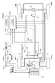
図1は本発明の実施の形態の四輪駆動車の制御装置を示す全体システム図である。
この実施の形態を適用した車両は、左右前輪WFL,WFRを主駆動輪とし左右後輪WRL,WRRを副駆動輪とした前輪駆動ベースの四輪駆動車である。すなわち、この車両は、エンジン1および図外の変速機を含むパワーユニットPUの駆動力が、トランスファ2およびフロントディファレンシャル3を介して左右の前輪WFL,WFRに直接伝達され、さらに、パワーユニットPUの駆動力が、トランスファ2,プロペラシャフト4,クラッチ装置5、リアディファレンシャル6を介して左右の後輪WRL,WRRに伝達される構成となっている。なお、前記パワーユニットPUには、スロットル開度を変更させるスロットル装置1sが設けられている。
【0010】
前記クラッチ装置5は、特許請求の範囲のトルク配分手段に相当するもので、このクラッチ装置5を完全に解放させた状態では、左右前輪WFL,WFRと左右後輪WRL,WRRとの駆動力配分比は、100:0となり、一方、クラッチ装置5を完全に締結させた状態では、左右前輪WFL,WFRと左右後輪WRL,WRRとの駆動力配分比は、50:50となる。
よって、クラッチ装置5の締結状態を変更することにより、前輪WFL,WFRと後輪WRL,WRRとの駆動力配分を、100:0〜50:50の範囲で任意に変更することができる。
なお、本実施の形態では、主駆動輪である前輪の車輪速度が副駆動輪である後輪の車輪速度よりも大きくなると、後輪に対する駆動力配分を高くして4輪駆動状態とする制御を実行するが、本実施の形態の場合、このように4輪駆動状態とするのは発進性を確保するために実行するものであるため、例えば20km/h程度の所定速度以下の低速領域でのみ、4輪駆動状態に制御し、前記所定速度よりも高速の速度領域では4輪駆動側に制御しないものとする。
【0011】
また、本実施の形態を適用した車両には、ブレーキユニットBUが搭載されている。このブレーキユニットBUは、運転者の制動操作に応じて制動圧を発生させるマスタシリンダMCと、各輪に制動圧に応じた制動力を与える図外のホイールシリンダとを結ぶブレーキ油圧回路の途中に設けられている。
そして、このブレーキユニットBUは、図示を省略した圧力制御弁を有し、マスタシリンダMCで発生した制動圧を、4つの図外のホイールシリンダに対して任意に減圧や増圧させて任意の圧力に調整してから伝達可能に構成されているとともに、圧力を発生させるポンプを有し、マスタシリンダMCにおいて制動圧が発生していない状態でも能動的に所望の制動圧を発生させて任意のホイールシリンダへ供給することが可能に構成されている。
よって、このブレーキユニットBUは、運転者が制動操作を行ったときに車輪がロックしそうになった場合には、その輪の制動圧を減圧させるとともに、最適の制動圧に向けて制御することで制動時の車輪ロックを防止するいわゆるABS制御と、旋回時などに車両が過度のオーバステアあるいはアンダステア状態となったときに、ニュートラルステア方向に戻す方向にヨーモーメントが発生するように所望の輪に能動的に制動力を発生させて車両姿勢の安定化を図るいわゆるVDC制御と、を実行することができる。
なお、上述のようなABS制御およびVDC制御を実行可能なブレーキユニットBUは、周知であるのでその詳細については説明を省略する。
【0012】
前記パワーユニットPUのエンジン1およびスロットル装置1sの作動はエンジンコントローラECUにより制御される。
また、パワーユニットPUに設けられている図外の変速機の作動はATコントローラATCUにより制御される。
また、前記クラッチ装置5の作動は、トルク配分コントローラTRQCUにより制御される。
【0013】
また、前記ブレーキユニットBUの作動は、トルク・制動コントローラBCUにより制御される。
すなわち、このトルク・制動コントローラBCUは、前記ブレーキユニットBUを作動させて前述のVDC制御およびABS制御を実行するもので、車輪速度センサ11から各輪WFL,WFR,WRL,WRRの速度に相当する信号を入力し、かつ、ヨーレート/Gセンサ12から車両に発生しているヨーレートおよび前後加速度を示す信号を入力し、圧力センサ13からマスタシリンダMCから供給される制動液圧に相当する信号を入力し、さらに、エンジンコントローラECUからエンジン回転数、エンジントルク、スロットル開度に相当する信号を入力し、また、ATコントローラATCUから、ギア位置を示す信号を入力し、舵角センサユニット14から舵角を示す信号を入力し、これらの入力に基づいて車両の状況を把握して、予め設定された制御則に基づいて、前述したVDC制御およびABS制御を実行するものである。
【0014】
さらに、このトルク・制動コントローラBCUは、TCS制御も実行する。このTCS制御は、各輪WFL,WFR,WRL,WRRのスリップ状態に基づいてスロットル装置1sあるいはブレーキユニットBUを作動させてスリップを抑制するTCS制御を実行するもので、スロットル装置1sを作動させる場合、エンジントルクダウン要求信号を、通信によりエンジンコントローラECUへ出力し、このエンジンコントローラECUが、エンジントルクダウン要求信号に基づいてスロットル装置1sおよびエンジン1を制御する。
また、このTCS制御におけるスリップ判断は、詳細な説明は省略するが、左右前輪WFL,WFRの車輪速度の平均値と、左右後輪WRL,WRRの車輪速度の平均値とを比較し、主駆動輪である前輪車輪速度平均値が後輪車輪速度平均値よりも設定値以上高くなったときにスリップ状態と判断する。そして、このスリップ状態判断時には、エンジン1の出力を低下するようにスロットル装置1sなどを作動させて主駆動輪である前輪WFL,WFRのスリップを抑制する。また、このTCS制御にあっては、エンジン1の出力低下量を最適に制御するべく正確な車体速度を検出するために、クラッチ装置5を解放側に制御させて、副駆動輪である後輪WRL,WRRを従動輪化させるものとする。
【0015】
次に、前記トルク配分コントローラTRQCUは、エンジンコントローラECUからエンジン回転数、スロットル開度を入力し、また、ATコントローラATCUからギア位置信号を入力し、トルク・制動コントローラBCUから、各輪WFL,WFR,WRL,WRRの車輪速度、VDC作動信号、TCS作動信号、ABS作動信号、ストップランプスイッチ信号などを通信により入力し、予め決められた制御則に従った制御演算を行い、その演算で得られた締結力が得られるようにクラッチ装置5へ駆動信号を出力する。
加えて、このトルク配分コントローラTRQCUは、トルク・制動コントローラBCUと連携して、本発明の特徴とする空転抑制ブレーキ制御を実行する。
【0016】
以下に、トルク配分コントローラTRQCUの詳細について説明する。
図2はこのトルク配分コントローラTRQCUを示すブロック図である。
データ受信部20では、トルク・制動コントローラBCUから各輪の車輪速度VWFR,VWFL,VWRR,VWRLと、VDC作動信号fVDCATと、TCS作動信号fTCSATと、ABS作動信号fABSATとを入力する。加えて、ストップランプスイッチ15からの信号に基づいてストップランプスイッチ信号STSをセットするとともに、エンジンコントローラECUからの入力に基づいてスロットル開度ACCをセットする。
【0017】
車体速度計算部21では、各車輪速度VWFR,VWFL,VWRR,VWRLに基づいて、車体速度VFの演算を行う。ちなみに、車体速度VFは、副駆動輪の車輪速度の平均値を用い、これを前後加速度により補正して求める。
前輪平均速度計算部22では、左右前輪WFL,WFRの車輪速度VWFL,VWFRの平均速度VWFを求める。
前輪左右速差計算部23では、前輪左右速度差DVWF=VWFR−VWFLの計算を行う。
後輪平均速度計算部24では、左右後輪WRL,WRRの車輪速度VWRL,VWRRの平均速度VWRを求める。
後輪左右速差計算部25では、後輪左右速度差DVWR=VWRR−VWRLの計算を行う。
前後回転数差計算部26は、前後の平均速度VWF,VWRの差である前後回転数差DVWを、DVW=VWF−VWRにより求める。
前後回転数速度差ゲイン計算部27は、予め設定されているマップと、前記車体速度計算部21で求めた車体速度VFから、ゲインKhを計算する。
前後回転数差制御トルク計算部28は、前後回転数速度差ゲイン計算部27で得られたゲインKhと、前後回転数差計算部26で得られた前後回転数差DVWに基づいて、Kh×DVWの計算により前後回転数差に感応した前後回転数差制御トルクTDVを演算する。
イニシャルトルク計算部29は、車体速度計算部21で得られた車体速度VFに基づいてイニシャルトルクTVを計算するもので、このイニシャルトルクTVは、車体速度VFの低速領域では一定で、車体速度VFが大きくなるにつれて小さくなる特性になっている。
【0018】
スロットル感応制御トルク計算部30は、車体速度計算部21で得られた車体速度VFと、データ受信部20から得られたスロットル開度ACCに基づいて車体速度VFが20km/hであるときに、スロットル開度ACCに応じた理想トルクであるスロットル感応制御トルクTSを、予め入力したマップに基づいて求める。なお、スロットル感応制御トルクTSの特性は、図示のように、スロットル開度ACCが低開度域ではスロットル開度ACCに対応してスロットル感応制御トルクTSが変動し、中開度域ではスロットル感応制御トルクTSを一定トルクとし、高開度域ではスロットル開度ACCに応じてさらにスロットル感応制御トルクTSが変動する特性となっている。
【0019】
空転抑制ブレーキ制御演算部31は、データ受信部20から得られた各車輪速度VWFR,VWFL,VWRR,VWRLに基づいて車輪の空転を判断し、さらに、前輪平均速度計算部22,前輪左右速差計算部23,後輪平均速度計算部24,後輪左右速差計算部25から得られた各平均速度VWF,VWR、各左右速度差DVWF,DVWR、前後回転数差DVWに基づいて、空転抑制ブレーキ制御時トルクTBと目標右前輪車輪速度VWSFR,目標左前輪車輪速度VWSFL,目標右後輪車輪速度VWSRR,目標左後輪車輪速度VWSRLを計算する。また、VDC作動信号fVDAT,TCS作動信号fTCSAT,ABS作動信号fABSAT,ストップランプスイッチ信号STSに基づいて、空転抑制ブレーキ制御許可判断を行い、空転抑制ブレーキ制御中に空転抑制ブレーキ制御フラグfBRをセットする。
【0020】
トルク選択第1ステージ部32は、前後回転数差制御トルク計算部28で得られた前後回転数差制御トルクTDVと、イニシャルトルク計算部29で得られたイニシャルトルクTVと、スロットル感応制御トルク計算部30で得られたスロットル感応制御トルクTSのセレクトハイにより目標トルクT1を決定する。
トルク選択第2ステージ部33は、前記トルク選択第1ステージ部32で得られた目標トルクT1と、前記空転抑制ブレーキ制御演算部31から得られた空転抑制ブレーキ制御時トルクTBおよび空転抑制ブレーキ制御フラグfBRとに基づいて目標トルクT2を決定する。すなわち、fBR=0のときは、目標トルクT2として目標トルクT1を選択し、fBR=1のときには、目標トルクT2として空転抑制ブレーキ制御時トルクTBを選択する。
【0021】
トルク決定部34は、目標トルクT2に対して、トルク増加/減少のフィルタ処理を行い、目標トルクTEを決定する。すなわち、目標トルクT2の急変をある程度緩和させるためにフィルタリング処理を行う。
トルク〜電流変換部35は、予め設定されたクラッチ装置5の特性であるトルク−電流値変換式に基づいて、目標トルクTEに対応した目標電流値Iを決定する。
クラッチ出力部36は、クラッチ装置5に向けて目標電流値Iを出力する。
また、データ通信部37は、空転抑制ブレーキ制御演算部31で得られた目標右前輪車輪速度VWSFR,目標左前輪車輪速度VWSFL,目標右後輪車輪速度VWSRR,目標左後輪車輪速度VWSRLをトルク・制動コントローラBCUに向けて送信する。なお、この送信を受けたトルク・制動コントローラBCUは、各車輪速度を目標値に制御すべく所望の輪に能動的に制動力を与える制御を実行する。
【0022】
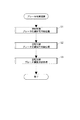
次に、空転抑制ブレーキ制御演算部31における処理を図3,図4,図5,図6のフローチャートに基づいて説明する。
まず、図3は、空転抑制ブレーキ制御演算部31における全体的な処理流れを示している。
この空転抑制ブレーキ制御演算部31にあっては、まず、ステップS1において、空転抑制ブレーキ制御を実行してよいか否かの判断である空転抑制ブレーキ制御許可判断処理を実行する。
次に、ステップS2に進んで、空転抑制ブレーキ制御を実行するか否かの判断である空転抑制ブレーキ制御実行判断処理を実行する。
最後に、ステップS3に進んで、空転抑制ブレーキ制御時トルクTBを決定して出力する処理である空転抑制ブレーキ制御決定処理を実行する。
【0023】
次に、各ステップS1,S2,S3について詳細に説明する。
まず、ステップS1の空転抑制ブレーキ制御許可判断処理を図4のフローチャートに基づいて説明する。
ステップ100では、許可フラグが0であるか否か判断し、許可フラグ=0の場合はステップ101に進み、許可フラグ=1の場合はステップ106に進む。なお、許可フラグは、空転抑制ブレーキ制御の許可判断時に=1にセットされるフラグであって、初期設定時には0にリセットされている。
次に、ステップ101では、4輪の車輪速度VWFR,VWFL,VWRR,VWRLのうちで最も低い値であるセレクトロー値(この値は、車体速度に最も近い値である)が、所定値(例えば、20km/hであり、この値は4駆制御の実行域を示す)未満であるか否か判断し、セレクトロー値<所定値の場合はステップ102に進み、セレクトロー値≧所定値の場合は、空転抑制ブレーキ制御許可判断を終了する。ちなみに、前記所定値(例えば、20km/h)は、前述したように、発進性を確保するために4輪駆動側に制御する速度域の設定値であり、このステップ101では、4輪駆動側に制御する領域であるか否かを判断している。すなわち、空転抑制ブレーキ制御は、4輪駆動状態における片輪スリップ発生時における発進性確保を目的としているため、このように4輪駆動側に制御する速度域であるか否かを判断している。
【0024】
次のステップ102では、VDC,TCS,ABSのいずれの制御も非実行中であるか否か判断し、いずれも非実行中であればステップ103に進み、いずれかの制御を実行している場合は、空転抑制ブレーキ制御許可判断を終了する。なお、このVDC,TCS,ABS各制御の判断は、トルク・制動コントローラBCUから送られる各作動信号fABSAT,fVDCAT,fTCSATに基づいて、これらが全て=0のときにYESと判断してステップ103に進む。
【0025】
次のステップ103では、スロットル開度ACCが予め設定された所定値(例えば10%)≧であるか否か判断し、ACC≧所定値の場合はステップ104に進み、ACC<所定値の場合は空転抑制ブレーキ制御許可判断を終了する。すなわち、このステップ103では、運転者がアクセルをある程度踏み込んで、走破性が求められる状態であるか否かを判断している。
【0026】
次のステップ104では、ストップランプスイッチ信号STSに基づいてストップランプがOFFであるか否か、すなわち運転者が制動操作を行っていないか否か判断し、ストップランプがOFFの場合はステップ105に進み、ストップランプがONの場合には空転抑制ブレーキ制御許可判断を終了する。すなわち、空転抑制ブレーキ制御は、発進性・走破性を確保する制御であるため、運転者が制動を行っている場合には、この空転抑制ブレーキ制御は許可されない。
【0027】
上記ステップ101〜104において、全てYESと判断された場合、ステップ105に進んで制御許可フラグを=1にセットする。
すなわち、セレクトロー車輪速度が4駆制御の実行域であることを示す所定の車速未満であり、VDC,TCS,ABSのいずれの制御を実行しておらず、スロットル開度ACCが所定値以上で加速状態を示しており、かつ、運転者が制動操作を行っていない場合に、空転抑制ブレーキ制御の許可と判定して制御許可フラグ=1にセットする。
【0028】
このように、いったん制御許可フラグ=1にセットされると、次回からステップ100の許可フラグ判断においてNOと判断されてステップ106に進むことになる。
このステップ106〜109にあっても、上記のステップ101〜104の各ステップと同様の判断を行い、セレクトロー車輪速度が所定値以上となるか、VDC,TCS,ABSのいずれかの制御が実行されるか、スロットル開度が所定値未満となるか、運転者が制動操作を行ってストップランプがOFFとなるか、してステップ106〜109のいずれかのステップでYESと判断されると、ステップ110に進んで、制御許可フラグ=0にリセットする。
なお、ステップ106にあっては、セレクトロー車輪速度と比較する所定値は、ステップ101の所定値よりも大きな値として制御ハンチングを防止するようにするのが好ましいものであり、例えば、ステップ101の所定値が20km/hであればこのステップ106では、25km/h程度の値とするのが好ましい。一方、ステップ108における所定値は、ステップ103の所定値よりも低い値にするのが好ましいものであり、例えば、ステップ103の所定値を10%とした場合、ステップ108では所定値を5%とする。
【0029】
次に、ステップS2の空転抑制ブレーキ制御実行判断処理について、図5のフローチャートにより説明する。
ステップ200〜202および207では、片輪スリップの発生を判断する。
まず、ステップ200では、片輪スリップの判断しきい値である前輪制御しきい値SLIPFBを計算する。この前輪制御しきい値SLIPFBの計算の一例を示せば、通常は、予め設定した第1所定値(例えば、10km/h)にセットし、既に前輪のいずれかに対して空転抑制ブレーキ制御が実行されている場合には、第1所定値よりも小さな第2所定値(例えば、5km/h)にセットする。あるいは、この前輪制御しきい値SLIPFBを車速に応じて異ならせるようにしてもよい。
次のステップ201では、後輪制御しきい値SLIPRBを計算する。この後輪制御しきい値SLIPRBも、例えば上述の前輪制御しきい値SLIPFBと同じようにして求める。ここで、後輪制御しきい値SLIPRBは、前輪制御しきい値SLIPFBと異ならせてもよい。すなわち、主駆動輪である前輪は、トルク伝達量が副駆動輪である後輪に比べて大きくなりがちであるから、左右車輪速差が大きく現れやすい。そこで、後輪制御しきい値SLIPRBは、前輪制御しきい値SLIPFBよりも小さめの値とするようにしてもよい。
【0030】
次のステップ202では、前輪左右速度差DVWFの絶対値が前輪制御しきい値SLIPFB以上であるかにより前輪において片輪スリップが発生しているか否かを判断し、|DVWF|≧SLIPFBであって片輪スリップが発生していると判断した場合はステップ203に進み、|DVWF|<SLIPFBであって片輪スリップが発生していないと判断した場合はステップ206に進む。
【0031】
ステップ202において前輪において片輪スリップが発生した場合に進むステップ203では、前輪左右速度差DVWFの符号のチェックを、DVWF≧0であるか否かにより行う。すなわち、前輪左右速度差DVWFは、右前輪車輪速度VWFRから左前輪車輪速度VWFLを差し引いて求めているため、左右のいずれの車輪速度が空転しているかを、DVWF≧0により判断し、DVWF≧0であって右前輪空転の場合はステップ204に進み、DVWF<0であって左前輪空転の場合はステップ205に進む。
【0032】
右前輪空転判断時に進むステップ204では、右前輪制御フラグfBR_FR=1、左前輪制御フラグfBR_FL=0にセットする。
左前輪空転判断時に進むステップ205では、右前輪制御フラグfBR_FR=0、左前輪制御フラグfBR_FL=1にセットする。
また、ステップ202において非空転と判断して進むステップ206では、右前輪制御フラグfBR_FR=0、左前輪制御フラグfBR_FL=0にセットする。
【0033】
次のステップ207〜211は、後輪について片輪スリップ判断を行うとともに、その判断結果に基づいて右後輪制御フラグfBR_RRおよび左後輪制御フラグfBR_RLのセットを行う。これらのステップ207〜211は、ステップ202〜206に対応しているため説明は省略する。なお、相違点は、ステップ207において、後輪左右速度差DVWRと後輪制御しきい値SLIPRBとの比較を行う点である。ここで、後輪制御しきい値SLIPRBと前輪制御しきい値SLIPFBとは、同一の値を用いてもよいし、車両特性に応じて異なる値を用いるようにしてもよい。
【0034】
次に、ステップ212では、空転抑制ブレーキ制御の実行許可を示す制御許可フラグが=1にセットされているか否か判断し、制御許可フラグ=1の場合には、ステップ213に進み、制御許可フラグ=0の場合にはステップ215に進む。
ステップ212にて制御許可フラグ=1の場合に進むステップ213では、4輪の制御フラグfBR_FR,fBR_FL,fBR_RR,fBR_RLのいずれかが1にセットされているか否か判断し、いずれかが1にセットされている場合はステップ214に進んで、空転抑制ブレーキ制御フラグfBR=1にセットし、いずれの制御フラグfBR_FR,fBR_FL,fBR_RR,fBR_RLも=0である場合にはステップ215に進んで、空転抑制ブレーキ制御フラグfBR=0にリセットする。
すなわち、制御許可フラグ=1にセットされ、4輪の制御フラグfBR_FR,fBR_FL,fBR_RR,fBR_RLが=1にセットされている場合に、空転抑制ブレーキ制御フラグfBR=1にセットされ、制御許可フラグ=0あるいは制御許可フラグは=1にセットされていても4輪の制御フラグfBR_FR,fBR_FL,fBR_RR,fBR_RLが=0である場合は、空転抑制ブレーキ制御フラグfBRは、=0とされる。
【0035】
したがって、上記の空転抑制ブレーキ制御実行判断にあっては、前輪と後輪とのいずれかあるいは両方において、左右車輪速度差DVWF,DVWRがしきい値SLIPFB,SLIPRBを超え、かつ、制御許可フラグ=1である場合に、空転抑制ブレーキ制御フラグが=1にセットされて、空転抑制ブレーキ制御実行と判断されるものである。
【0036】
次に、ステップS3の空転抑制ブレーキ制御決定処理の詳細を図6のフローチャートに基づいて説明する。
ステップ300〜302では、空転輪(前輪)の前輪目標車輪速度VBFRSを決定する。そのため、まず、ステップ300では、空転量が所定量よりも大きいか否かを判断すべく、前輪左右速度差DVWFの絶対値が所定値である20km/hよりも大きいか否か判断し、|DVWF|>20km/hであって空転量が大きい場合はステップ301に進んで前輪目標車輪速度VBFRS=VWF(前輪平均速度)にセットし、|DVWF|≦20km/hであって空転量が大きくない場合はステップ302に進んで前輪目標車輪速度VBFRSを右前輪車輪速度VWFRと左前輪車輪速度VWFLの小さい方の値とする。
すなわち、空転量が所定値以下で空転量が比較的小さい場合には、目標車輪速度を非空転輪である左右の他方の車輪速度とするが、空転量が大きい場合には、目標車輪速度をいったん、左右輪の平均速度とする。これは、片輪の空転量が大きい場合に、強い制動力を与えると、車両挙動が不安定になるおそれがあるため、このような場合には、徐々に制動力を与えるようにして、車両挙動の安定化を図っている。
【0037】
続くステップ303〜305では、後輪目標車輪速度VBRRSを決定する。この場合も、前輪と同様にステップ303において後輪左右速度差DVWRの絶対値が20km/hよりも大きいか否か判断し、|DVWR|>20km/hの場合はステップ304に進んで後輪目標車輪速度VBRRS=VWR(後輪平均速度)にセットし、|DVWR|≦20km/hの場合はステップ305に進んで後輪目標車輪速度VBRRSを右後輪車輪速度VWRRと左後輪車輪速度VWRLの小さい方の値とする。
【0038】
次のステップ306では、右前輪制御フラグfBR_FRが1にセットされているか否か判断し、fBR_FR=1の場合はステップ307に進み、fBR_FR=0の場合はステップ308に進む。そして、ステップ307では、目標右前輪車輪速度VWSFR=VBFRSとし、ステップ308では、目標右前輪車輪速度VWSFR=初期値とする。なお、この初期値としては、例えばデータの最大値をセットする。
同様の処理の各輪について行う。
すなわち、ステップ309〜311では、左前輪制御フラグfBR_FL=1の場合は、ステップ310において目標左前輪車輪速度VWSFL=VBFRSとし、fBR_FL=0の場合は、ステップ311において目標左前輪車輪速度VWSFL=初期値とする。
また、ステップ312〜314では、右後輪制御フラグfBR_RR=1の場合は、ステップ313において目標右後輪車輪速度VWSRR=VBRRSとし、fBR_RR=0の場合はステップ314において目標右後輪車輪速度VWSRR=初期値とする。
また、ステップ315〜317では、左後輪制御フラグfBR_RL=1の場合は、ステップ316において目標左後輪車輪速度VWSRL=VBRRSとし、fBR_RL=0の場合はステップ317において目標左後輪車輪速度VWSRL=初期値とする。
【0039】
以上のようにして各輪の目標車輪速度が決定したら、ステップ318〜320において、空転抑制ブレーキ制御時トルクTBを決定するものであり、まず、ステップ318において前後回転数差DVWが所定値(−3km/h)以上であるか否か判断し、DVW≧−3km/hであって前輪がスリップしている場合はステップ319に進み、DVW<−3km/hであって後輪がスリップしている場合はステップ320に進む。
ステップ319では、空転抑制ブレーキ制御時トルクTBを前後のトルク配分が50:50となるリジッドトルクをセットし、その後、処理を終了する。
また、ステップ320では、後輪のスリップが大きい状態であるため、後輪側のトルクを減少させてスリップを抑制することを目的として、空転抑制ブレーキ制御時トルクTBを、TB=リジッドトルク−k×|DVW|により求めた後、処理を終了する。ここで、kは係数であり、予め設定されている。
なお、ステップ318において、前後回転数差DVWを所定値と比較するにあたり、所定値として−3km/hを用いているのは、後輪がスリップしても後輪のトルクを減じるステップ320に進む処理を実行しない不感帯を設定しているもので(すなわち、−3km/h≦DVW<0の領域は、前輪に対して後輪がスリップしているが後輪のトルクを減少させる処理には進まない)、この所定値としては、明らかに後輪がスリップしていると判断できる値であれば、この−3km/h以外の値(例えば、−1km/h〜−7km/hの範囲内の任意の値など)を用いるようにしてもよい。
【0040】
次に、実施の形態の作動について説明する。
雪道発進時などのように、例えば、20km/hなどのような所定車速未満において、主駆動輪である左右前輪WFL,WFRがスリップして前輪の平均速度VWFが後輪の平均速度VWRよりも所定以上大きくなると、トルク配分コントローラTRQCUは、クラッチ装置5を締結させて左右後輪WRL,WRRに対してトルク伝達を行って、4輪駆動状態とする。
このような4輪駆動状態において、左右で路面摩擦係数が異なるスプリットμや1輪のみが路面摩擦係数が低い部分を通過するなどして、前後輪の両方あるいは一方で片輪スリップが発生したときには、本実施の形態では以下のような作動を行う。なお、このとき、雪道発進時を想定し、運転者は制動操作を行っていないものとするとともに、旋回時などにおいて車両挙動を安定させるVDC制御も実行されていないものとする。
【0041】
上記のように、車体速度VFが所定値以下である発進時にあっては、4輪セレクトロー値が所定値以下となるため、図4に示す空転抑制ブレーキ制御許可判断処理では、ステップ100→101→102の流れとなる。
このステップ102では、ABS制御、VDC制御、TCS制御が非作動であるか否かの判断を行うが、ABS制御およびVDC制御については上述したようにに実行されていない。ここで、TCS制御であるが、片輪スリップが発生しても以下に述べる理由によりこの時点では生後が実行されていない。よって、ステップ102では、YESと判断して次のステップ103に進む。
ここで、TCS制御が実行されていない理由について説明すると、前述したようにTCS制御は前輪の平均速度VWFと後輪の平均速度VWRとの差に基づいて実行する。それに対し、片輪スリップ発生に対応して実行される空転抑制ブレーキ制御は、左右の車輪速度差DVWF,DVWRに基づいて実行される。ここで左右の車輪速度差DVWF,DVWRと、前後の平均速度差とを比較した場合、左右の車輪速度差DVWF,DVWRの方が変化が顕著に現れる。したがって、片輪スリップが発生した場合には、TCS制御よりも空転抑制ブレーキ制御の方が制御に入りやすい(なお、空転抑制ブレーキ制御が実行される手順については後述する)。よって、説明している作動例のように、片輪スリップが発生した場合、この図4に示す空転抑制ブレーキ制御許可判断処理のステップ102の判断を行う時点で、TCS制御は実行されていない。
【0042】
また、この作動例にあっては、発進時であるので、ステップ103においてスロットル開度≧所定値であることからステップ104に進み、前述したようにこのとき運転者は制動操作を行っていないことから、ストップランプスイッチ15がOFFでステップ105に進んで、制御許可フラグ=1にセットする。
また、この後も、運転者は、発進操作を続行し、4輪セレクトロー値<所定値であり、ABS制御、VDC制御、TCS制御が成されず、スロットル開度≧所定値、ストップランプスイッチOFFの状態が維持されるため、ステップ100→106→107→108→109→終了の流れとなって、制御許可フラグ=1の状態が続く。
【0043】
そこで、図5に示す空転抑制ブレーキ制御実行判断処理では、まず、ステップ200,201において、前輪と後輪の制御しきい値SLIPFB,SLIPRBをセットする。この場合、例えば、空転抑制ブレーキ制御に入る前はSLIPFB,SLIPRB=10km/hにセットし、空転抑制ブレーキ制御の開始後は、SLIPFB,SLIPRB=5km/hにセットする。
【0044】
そして、前輪において片輪スリップが発生している場合、その左右車輪速度差である前輪左右速度差DVWFの絶対値が前輪制御しきい値SLIPFB以上となると、ステップ202→203に進み、片輪スリップが発生している輪が左右のいずれかを判断し、次のステップ204もしくは205により各輪の制御フラグのセットを行う。
ここで、片輪スリップが右輪に発生しているとすると、ステップ204に進んで、右前輪制御フラグfBR_FR=1にセットする。
また、前輪において片輪スリップが発生していない場合には、左右前輪制御フラグfBR_FR,fBR_FL=0とする。
【0045】
一方、後輪についてもステップ207〜211に基づいて、左右後輪制御フラッグfBR_RL,fBR_RRのセットを必要に応じ行うものであり、上記と同様に右輪がスリップしている場合、ステップ207→208→209の流れとなって右後輪制御フラグfBR_RR=1にセットする。
【0046】
さらに、片輪スリップが発生している場合には、ステップ212→213→214の流れとなって空転抑制ブレーキ制御フラグfBR=1にセットされる。
【0047】
そこで、図6に示す空転抑制ブレーキ制御決定処理にあっては、前輪で片輪スリップが発生している場合にはステップ300〜302において前輪目標車輪速度VBFRSを設定し、同様に後輪で片輪スリップが発生している場合にはステップ303〜305で、後輪目標車輪速度VBRRSを設定する。この場合、ステップ300および303で、それぞれ前輪・後輪左右速度差DVWF,DVWRの絶対値が、所定値である20km/hよりも大きいか否かを判断し、前輪・後輪の各左右速度差DVWF,DVWRの絶対値が、20km/h以下であれば空転してない方の車輪速度、すなわち、上述のように前後において右輪が空転している場合には、前輪目標車輪速度VBFRS=VWFL、後輪目標車輪速度VBRRS=VWRLとする。また、前輪・後輪の各左右速度差DVWF,DVWRの絶対値が20km/hよりも大きい場合には、前輪目標車輪速度VBFRSを前輪の平均速度VWF、後輪目標車輪速度VBRRSを後輪の平均速度VWRとする。
【0048】
そして、右前輪についてはステップ306〜308で、左前輪についてはステップ309〜311で、右後輪についてはステップ312〜314で、左後輪についてはステップ315〜317で、それぞれ、目標車輪速度VWSFL,VWSFR,VWSRL,VWSRRを設定するものであり、空転抑制ブレーキ制御の対象輪(本例では、右前輪および右後輪)は、目標右前輪車輪速度VWSFRおよび目標右後輪車輪速度VWSRRを、前輪目標車輪速度VBFRSと後輪目標車輪速度VBRRSに設定し、空転が生じていない前後左輪に関しては、目標左前輪車輪速度VWSFLおよび目標左後輪車輪速度VWSRLを、初期値(制動力を与えない値)とする。
【0049】
最後に、ステップ318〜320において、空転抑制ブレーキ制御時トルクTBを決定するもので、後輪のみが空転している場合に限り、後輪へのトルク配分を減じるが、それ以外は、クラッチ装置5をリジッド状態、すなわち前後のトルク配分比を50:50とする。
【0050】
上述してきたように、本実施の形態にあっては、雪道発進時において右前輪および右後輪が空転している場合には、空転抑制ブレーキ制御により、右前輪および右後輪に対して、それぞれ、制動力が与えられ、空転が防止される。このとき、右前輪および右後輪の空転が大きくない場合、すなわち、左右車輪速度差が20km/h以下の場合は、右前輪および左後輪の車輪速度が、それぞれ左前輪および左後輪に一致するよう、制動力が制御される。
一方、右前輪および右後輪の空転が大きい場合、すなわち、左右車輪速度差が20km/hよりも大きい場合には、まず、右前輪および左後輪の車輪速度が、それぞれ前輪・後輪の平均速度VWF,VWRを目指して制動力を与え、その後、左右車輪速度差が20km/h以下に低下すると、左前輪および左後輪の車輪速度に一致するように制御する。
同時に、クラッチ装置5は、後輪のみがスリップしている場合を除いて、リジッドに制御する。すなわち、本例のように、雪道における発進時には、主駆動輪である左右前輪側の方がスリップ量が大きくなりやすく、この場合、リジッドなトルク配分となる。
【0051】
よって、本実施の形態にあっては、空転抑制ブレーキ制御実行時には、トルク配分手段としてのクラッチ装置5により副駆動輪である左右後輪WRL,WRRに対して最大限のトルクが伝達された状態で、片輪スリップ状態で空転している車輪、すなわち本例では、右前輪WFRおよび右後輪WRRに対して、空転していない左前輪WFLおよび左後輪WRLの車輪速度に一致するまで制動力が与えられる。このように、発進性および走破性を最大としたリジッド4輪駆動状態で片輪スリップを抑制するため、従来に比べて、発進性および走破性が非常に高い状態で、片輪スリップを解消することができる。
なお、上述の空転抑制ブレーキ制御は、発進後、図4に示すように、車速が上がって4輪セレクトロー値が、例えば20km/h程度の所定値以上となるか、VDC制御、TCS制御、ABS制御のいずれかが実行されるか、発進後、車速が安定するなどによりスロットル開度が所定値以下に戻されるか、運転者が制動操作を行うか、のいずれかにより、制御許可フラグが0にリセットされることにより、中止される。
さらに、実施の形態にあっては、上述のように制動力を与えて片輪スリップを解消するにあたり、既存の能動的に制動力を与えるブレーキユニットBUおよびその制御を行うトルク・制動コントローラBCUをそのまま利用することができ、製造コストを低く抑えることができる。
【0052】
(別の実施の形態)
以上、本発明の実施の形態について説明してきたが、本発明は、以下のような別の実施形態に具体化することができる。以下の別の実施の形態において、上記実施の形態と同様の作用および効果を得ることができる。
例えば、実施の形態では、主駆動輪を前輪としたが、主駆動輪を後輪とした車両にも適用できる。
また、実施の形態では、駆動源としてエンジンを示したが、これに限られず、モータなど他の駆動源を用いてもよい。
また、実施の形態では、前輪WFL,WFRと後輪WRL,WRRとの駆動力配分を、100:0〜50:50の範囲で実行するものを示したが、この駆動力配分比はこれに限定されず、これよりも狭い範囲で配分するようにしてもよい。
【0053】
また、実施の形態では、ステップ300〜305において、左右の車輪速度差に応じて目標車輪速度を決定する処理を行っている。この処理において左右の車輪速度差の一例として20km/hを示しているが、この速度は、20km/hに限定されるものではなく、車両の特性に応じて片輪に大きな制動力を与えた場合に車両挙動が変化するおそれのある車輪速度に応じて任意の値を設定するようにしてよい。また、この制動力は、片輪スリップ発生時に与えるものであるから、この場合、大きな制動力を与えても車両挙動が大きく変化するおそれがない場合には、この左右の車輪速度差に応じて目標車輪速度を異ならせる処理を実行する必要はなく、常に、左右の他方の非スリップ輪の車輪速度を目標車輪速度とするようにしてもよい。
【0054】
また、ステップ318〜320において、非駆動輪である後輪と主駆動輪である前輪との車輪速度差に応じて後輪へのトルク配分を決定する処理を行うようにしている。しかしながら、非駆動輪側が主駆動輪よりも大きくスリップすることはまれであるので、このような非駆動輪と主駆動輪との回転差に応じた処理を行うことなく、空転抑制制御時には、常に、主駆動輪と副駆動輪とのトルク配分を50:50とするリジッドトルク配分とするようにしてもよい。
【0055】
(請求項以外の技術思想)
さらに、上記実施の形態から把握し得る請求項以外の技術思想について、以下にその効果とともに記載する。
【0056】
イ)請求項1に記載の四輪駆動車の制御装置において、前記制御手段は、トルク配分手段により副駆動輪にトルク配分を行って4輪駆動状態とするのは、所定の車速未満の発進加速時であることとしたことを特徴とする四輪駆動車の制御装置。
このように、所定の車速未満の発進加速時のみに4輪駆動状態にトルク配分する構成において、片輪スリップ発生時に空転抑制ブレーキ制御を実行するようにすると、発進性および走破性が向上する効果が顕著に得られる。
【0057】
ロ)請求項1に記載の四輪駆動車の制御装置において、前記制御手段を、空転抑制ブレーキ制御許可条件が成立しているか否かの空転抑制ブレーキ制御許可判断を実行して空転抑制ブレーキ制御許可条件が成立している場合に、前記空転抑制ブレーキ制御を実行するよう構成し、かつ、空転抑制ブレーキ制御許可条件が、運転者が制動操作を行っていないこと、スロットル開度が所定値以上であること、制動および駆動トルク配分に関する他の制御を実行していないこと、車速が所定値以下のいずれかを含むことを特徴とする四輪駆動車の制御装置。
したがって、運転者が制動を行っていないことを許可条件とすることで、運転者の制動と、空転抑制ブレーキ制御による制動とが干渉しないとともに、運転者が制動を行って発進性および走破性を向上させることが不要であるときに、この発進性および走破性を向上させる空転抑制ブレーキ制御を無用に実行することがないようにできる。
同様に、スロットル開度が所定値以上であることを許可条件とすることで、運転者が発進性および走破性が必要な発進加速を行っていいない状態で、無用に空転抑制ブレーキ制御を実行しないようにできる。
同様に、制動および駆動トルク配分に関する他の制御を実行していないことを許可条件とすることで、空転抑制ブレーキ制御による制動力および駆動力配分制御と、他の制御による制動力あるいは駆動力配分制御とが制御干渉しないようにすることができる。
同様に、車速が所定値以下であることを許可条件とすることで、上記ア)に記載の四輪駆動車の制御装置のように4輪駆動状態とする速度域を限った場合に、不要に空転抑制ブレーキ制御を実行して、副駆動輪への駆動伝達系に負荷を与えないようにすることができる。
【0058】
ハ)請求項1に記載の四輪駆動車の制御装置において、
前記制御手段は、空転抑制ブレーキ制御を実行するにあたり、空転抑制ブレーキ制御を実行するか否かを判断する空転抑制ブレーキ制御実行判断を実行するよう構成され、かつ、この空転抑制ブレーキ制御実行判断において、スリップ判断しきい値を決定するしきい値決定処理を実行し、前輪と後輪とのいずれかの左右車輪速度差がスリップ判断しきい値以上となると、片輪スリップが発生したとして空転抑制ブレーキ制御の実行と判断するよう構成したことを特徴とする四輪駆動車の制御装置。
このように、スリップ判断閾値と左右車輪速度差との比較に基づいて片輪スリップ判断を行うので、片輪スリップ判断を容易に行うことができる。
また、しきい値決定処理において、空転抑制ブレーキ制御実行中は空転抑制ブレーキ制御実行前よりも、小さな値のしきい値を用いるようにすることで、制御ハンチングが生じないようにしながら、片輪スリップ発生輪の車輪速度を非発生輪の車輪速度に向けて収束させることができる。
また、しきい値決定処理において、主駆動輪のスリップ判断しきい値と副駆動輪のスリップ判断しきい値とを異ならせ、前者の方が後者よりも大きな値とすることができる。このようにすることで、トルク配分量が小さくなりがちで同じ条件であれば片輪スリップ発生時の左右車輪速差が小さくなりがちな副駆動輪にあっても、的確に空転抑制ブレーキ制御を実行することができる。
【0059】
ニ)請求項1に記載の四輪駆動車の制御装置において、
前記制御手段は、空転抑制ブレーキ制御を実行するにあたり、各輪の目標車輪速度およびトルク配分手段によるトルク配分目標値を決定する空転抑制ブレーキ制御決定処理を実行し、かつ、空転抑制ブレーキ制御実行時には、制御対象の車輪速度が目標車輪速度となるよう制動力を与えるようブレーキユニットに向けて制御出力を行うとともに、副駆動輪に対するトルク配分がトルク配分目標値となるようにトルク配分手段に向けて制御出力を行うことを特徴とする四輪駆動車の制御装置。
このように、空転している車輪に対して目標車輪速度に収束するように制動力を与えるように制御することにより、発生する制動力自体を制御するのに比べて制御性に優れる。
【0060】
ホ)上記ニ)に記載の四輪駆動車の制御装置において、
前記制御手段は、空転抑制ブレーキ制御決定処理を実行するにあたり、空転輪の目標車輪速度は、空転輪のスリップ量が所定量以下であるときには、左右輪の他方の非空転輪の車輪速度を目標車輪速度とし、空転輪のスリップ量が所定量よりも大きい場合には、左右輪の平均速度を目標車輪速度とすることを特徴とする四輪駆動車の制御装置。
したがって、片輪スリップが生じて空転抑制ブレーキ制御を実行するときに、空転量が所定以下の場合には、左右の他方の非空転輪と車輪速度が一致するように制動力を与えるが、空転量が大きい場合には、目標車輪速度を左右輪の平均車輪速度として、制御開始時に与える制動力を抑える。これにより、スリップ輪に急激に大きな制動力を与えることで、車両挙動が変化するのを防止することができる。なお、このように空転量が大きい場合に、目標車輪速度を低く抑えて制動力を与える制御を実行して、空転輪の空転量が下がってスリップ量が所定量以下になると、左右の他方の非空転輪の車輪速度を目標車輪速度とした制御に変わって非空転輪の車輪速度に収束する。
【0061】
ヘ)上記ニ)に記載の四輪駆動車の制御装置において、
前記制御手段は、空転抑制ブレーキ制御決定処理を実行するにあたり、主駆動輪と副駆動輪との回転差に基づき、副駆動輪の車輪速度が主駆動輪の車輪速度よりも所定値以上高い場合に、副駆動輪に対する駆動力配分を前記回転差に応じたトルク配分目標値を設定し、それ以外では、主駆動輪と副駆動輪とに均等にトルク配分を行うようにトルク配分目標値を設定するようにしたことを特徴とする四輪駆動車の制御装置。
したがって、一般に、トルク配分可変の四輪駆動車では、主駆動輪側のトルク配分が高くなることから、主駆動輪側にスリップが生じやすい。そこで、空転抑制ブレーキ制御を実行するにあたり、副駆動輪のスリップ量が所定量を超えない限りは、すなわち、副駆動輪の車輪速度が主駆動輪の車輪速度よりも所定値以上高くならない限りは、トルク配分目標値は、主駆動輪と副駆動輪とに均等にトルク配分を行うリジッド状態に制御して、発進性および走破性を確保することができる。
それに対して、万一、副駆動輪が過剰にスリップした場合、すなわち、副駆動輪の車輪速度が主駆動輪の車輪速度よりも所定値以上高くなった場合には、副駆動輪に対する駆動力配分を回転差に応じたトルク配分目標値を設定する。これにより、副駆動輪へのトルク配分量を適正に低下させて、副駆動輪のスリップ量を抑えながら、片輪スリップを抑制することができ、これにより、車両挙動の安定化を図りつつ片輪スリップを抑制することができる。
【図面の簡単な説明】
【図1】本発明実施の形態の四輪駆動車の制御装置を示す全体システム図である。
【図2】実施の形態の四輪駆動車の制御装置におけるトルク配分コントローラを示すブロック図である。
【図3】実施の形態の四輪駆動車の制御装置における空転抑制ブレーキ制御演算部の全体的な処理流れを示すフローチャートである。
【図4】実施の形態の四輪駆動車の制御装置における空転抑制ブレーキ制御許可判断処理の制御流れを示すフローチャートである。
【図5】実施の形態の四輪駆動車の制御装置における空転抑制ブレーキ制御実行判断処理の制御流れを示すフローチャートである。
【図6】実施の形態の四輪駆動車の制御装置における空転抑制ブレーキ制御決定処理の制御流れを示すフローチャートである。
【符号の説明】
1 エンジン(駆動源)
5 クラッチ装置(トルク配分手段)
11 車輪速度センサ(スリップ状態検出手段)
WFL 左前輪(主駆動輪)
WFR 右前輪(主駆動輪)
WRL 左後輪(副駆動輪)
WRR 右後輪(副駆動輪)
BU ブレーキユニット
TRQCU トルク配分コントローラ(制御手段)
BCU トルク・制動コントローラ(制御手段)[0001]
TECHNICAL FIELD OF THE INVENTION
The present invention executes a driving force distribution control for distributing a driving force of a power source to one main driving wheel of a front wheel and a rear wheel and the other sub driving wheel, and performs an idling that can actively generate a braking force. The present invention relates to a control device for a four-wheel drive vehicle equipped with a suppression brake control device.
[0002]
[Prior art]
Conventionally, based on a predetermined switching condition set in advance, a differential rotation control based on the difference between the rotational speeds of the left and right wheels and a yaw rate control based on a deviation between the target yaw rate and the actual yaw rate are appropriately switched, and the left and right driving forces are changed. A driving force distribution control device for a vehicle that performs distribution is described in, for example, Japanese Patent Application Laid-Open No. 7-164910.
In this conventional technique, the clutches provided on the left and right sides of the drive shaft are controlled, and the driving force distribution ratio applied to the left and right rear wheels (auxiliary driving wheels) is changed, thereby improving the running performance and steering stability of the vehicle. I try to make it. The above-described differential rotation control based on the difference between the left and right rotation speeds includes a rotation speed sensitive type for preventing the rotation speed difference between the left and right wheels from becoming larger than a predetermined value.
[0003]
Conventionally, there has been known a four-wheel drive vehicle that distributes driving force to one main drive wheel of a front wheel and a rear wheel and the other auxiliary drive wheel. Further, in such a vehicle, when a slip occurs during acceleration, a control device that executes control for suppressing the slip (hereinafter, this control is referred to as TCS control) is also known.
In the conventional TCS control, when a slip occurs during acceleration, the driving force transmitted to the sub-drive wheels is reduced or stopped to control the two-wheel drive, thereby controlling the rotation of the sub-drive wheels. After obtaining a high-precision vehicle speed by matching the speed to the vehicle speed, the driving force transmitted to the main drive wheels is reduced or braking force is applied to the main drive wheels, thereby suppressing slip. Control.
[0004]
[Problems to be solved by the invention]
However, in the former prior art, when a wheel speed difference occurs between the left and right rear wheels (auxiliary driving wheels), the driving force distribution to the left and right wheels (rear wheels) is provided on the drive shaft. That is, the driving force distribution control is performed only by controlling one of the sub-drive wheels (or the main drive wheels). For this reason, for example, when one wheel slips between the main drive wheel and the sub drive wheel, for example, when traveling on a so-called split μ road having different road surface friction coefficients on the left and right, the driving force is distributed to the sub drive wheels. However, since the one-wheel slip state of the main drive wheel cannot be eliminated, sufficient driving force cannot be given to the sub-drive wheel, so that there is a problem that startability or running performance cannot be improved. .
[0005]
Further, in the latter conventional technique, when one-wheel slip occurs in the drive wheels, the slip can be eliminated by the TCS control. However, since the slip is controlled by the two-wheel drive side to obtain an accurate vehicle speed, There was a problem that the starting performance or running performance was reduced. Such a problem is particularly remarkable when a vehicle having a front wheel as a main drive wheel starts on a slope. That is, on an uphill road, the wheel load of the front wheel, which is the main drive wheel, decreases. In this state, when one-wheel slip occurs in the main drive wheels and the TCS control is executed, if the drive power distribution ratio to the rear wheels is reduced to obtain an accurate vehicle speed, the torque of the front wheels as the main drive wheels is reduced. Becomes small, and the climbability is remarkably reduced.
[0006]
The present invention has been made in view of such a conventional problem, and when one of the left and right wheels slips during traveling, one wheel slip occurs while maintaining the four-wheel drive state. The purpose is to eliminate wheel slip and improve start-up and running performance.
[0007]
[Means for Solving the Problems]
In order to achieve the above object, according to a first aspect of the present invention, in the control device for a four-wheel drive vehicle, when a one-wheel slip occurs in which one of the left and right wheels slips, the driving force is applied to the auxiliary drive wheel. The control means executes the idling suppression brake control for activating the torque distribution means so as to transmit the information and for operating the brake unit so as to apply the braking force to the slip wheels.
[0008]
Therefore, in the present invention, when one of the left and right wheels slips on one or both of the main drive wheels and the sub drive wheels, the control means executes the idling suppression brake control. When the anti-skid brake control is executed, the torque is also transmitted to the sub-drive wheels by the torque distribution means, so that the torque of the drive source is transmitted to the four wheels, and for the spinning wheels, When the braking force is applied by the brake unit, the idling can be suppressed, and the escape of the driving torque can be suppressed.
As described above, according to the present invention, in the four-wheel drive state in which high starting performance and running performance are obtained, braking force is applied only to the slip wheel to suppress one-wheel slip. , The one-wheel slip can be eliminated.
Further, in order to eliminate the one-wheel slip by applying the braking force as described above, it is possible to reduce the manufacturing cost by using the existing brake unit that actively provides the braking force.
[0009]
BEST MODE FOR CARRYING OUT THE INVENTION
Hereinafter, a control device for a four-wheel drive vehicle according to an embodiment of the present invention will be described.
FIG. 1 is an overall system diagram showing a control device for a four-wheel drive vehicle according to an embodiment of the present invention.
The vehicle to which this embodiment is applied is a front-wheel drive four-wheel drive vehicle in which left and right front wheels WFL, WFR are main drive wheels, and left and right rear wheels WRL, WRR are auxiliary drive wheels. That is, in this vehicle, the driving force of the power unit PU including the
[0010]
The
Thus, by changing the engagement state of the
In the present embodiment, when the wheel speed of the front wheel, which is the main drive wheel, becomes higher than the wheel speed of the rear wheel, which is the auxiliary drive wheel, the drive power distribution to the rear wheel is increased, and the four-wheel drive state is set. In the case of the present embodiment, the four-wheel drive state is executed in order to ensure startability, and thus, for example, in a low-speed region of a predetermined speed of about 20 km / h or less. Only the four-wheel drive state is controlled, and control is not performed on the four-wheel drive side in a speed range higher than the predetermined speed.
[0011]
Further, a brake unit BU is mounted on a vehicle to which the present embodiment is applied. This brake unit BU is provided in the middle of a brake hydraulic circuit that connects a master cylinder MC that generates a braking pressure in accordance with a braking operation of a driver and a wheel cylinder (not shown) that applies a braking force to each wheel according to the braking pressure. Is provided.
The brake unit BU has a pressure control valve (not shown), and the brake pressure generated in the master cylinder MC is arbitrarily reduced or increased with respect to four wheel cylinders (not shown) to obtain an arbitrary pressure. The pump is configured to be capable of transmitting after adjusting the pressure, has a pump for generating pressure, and actively generates a desired braking pressure even when no braking pressure is generated in the master cylinder MC. It is configured to be able to supply to the cylinder.
Therefore, when the wheel is likely to lock when the driver performs the braking operation, the brake unit BU reduces the braking pressure of the wheel and controls the braking pressure toward the optimum braking pressure. The so-called ABS control for preventing wheel lock during braking, and active control of desired wheels so that a yaw moment is generated in the direction of returning to neutral steering when the vehicle is in an excessive oversteer or understeer state during turning or the like. The so-called VDC control for stabilizing the vehicle attitude by generating a braking force is performed.
Since the brake unit BU capable of executing the ABS control and the VDC control as described above is well known, a detailed description thereof will be omitted.
[0012]
The operations of the
The operation of a transmission (not shown) provided in power unit PU is controlled by AT controller ATCU.
The operation of the
[0013]
The operation of the brake unit BU is controlled by a torque / braking controller BCU.
That is, the torque / braking controller BCU operates the brake unit BU to execute the above-described VDC control and ABS control, and corresponds to the speed of each wheel WFL, WFR, WRL, WRR from the
[0014]
Further, the torque / braking controller BCU also executes TCS control. This TCS control executes TCS control for suppressing the slip by operating the throttle device 1s or the brake unit BU based on the slip state of each wheel WFL, WFR, WRL, WRR. An engine torque down request signal is output to the engine controller ECU through communication, and the engine controller ECU controls the throttle device 1s and the
Although the detailed description of the slip determination in the TCS control is omitted, the average value of the wheel speeds of the left and right front wheels WFL and WFR is compared with the average value of the wheel speeds of the right and left rear wheels WRL and WRR, and the main drive is performed. When the average value of the front wheel speeds of the wheels is higher than the average value of the rear wheel speeds by a set value or more, it is determined that the vehicle is in the slip state. When the slip state is determined, the throttle device 1s and the like are operated so as to reduce the output of the
[0015]
Next, the torque distribution controller TRQCU inputs the engine speed and the throttle opening from the engine controller ECU, inputs the gear position signal from the AT controller ATCU, and outputs the respective wheels WFL, WFR from the torque / brake controller BCU. , WRL, WRR, wheel speed, VDC operation signal, TCS operation signal, ABS operation signal, stop lamp switch signal, etc. are input by communication, and control calculation is performed according to a predetermined control law, and the calculation is obtained. A drive signal is output to the
In addition, the torque distribution controller TRQCU executes the idling suppression brake control, which is a feature of the present invention, in cooperation with the torque / brake controller BCU.
[0016]
Hereinafter, details of the torque distribution controller TRQCU will be described.
FIG. 2 is a block diagram showing the torque distribution controller TRQCU.
The
[0017]
The vehicle
The front wheel average speed calculation unit 22 calculates an average speed VWF of the wheel speeds VWFL, VWFR of the left and right front wheels WFL, WFR.
The front wheel left / right speed
The rear wheel average
The rear wheel left / right speed
The front-rear rotation
The longitudinal rotation speed difference
The front / rear rotation speed difference control
The initial torque calculator 29 calculates the initial torque TV based on the vehicle speed VF obtained by the
[0018]
When the vehicle speed VF is 20 km / h based on the vehicle speed VF obtained by the vehicle
[0019]
The anti-skid brake
[0020]
The torque selection
The torque selection
[0021]
The
The torque-
The
Further, the
[0022]
Next, the processing in the idling suppression brake
First, FIG. 3 shows an overall processing flow in the idling suppression brake
In the anti-skid brake
Next, the process proceeds to step S2, in which an anti-skid brake control execution determination process is executed, which is a determination as to whether or not to execute the anti-skid brake control.
Finally, the process proceeds to step S3, in which an anti-skid brake control determination process is performed, which is a process for determining and outputting the anti-skid brake control torque TB.
[0023]
Next, steps S1, S2, and S3 will be described in detail.
First, the idling suppression brake control permission determination process in step S1 will be described with reference to the flowchart in FIG.
In
Next, in
[0024]
In the
[0025]
In the
[0026]
In the
[0027]
If YES is determined in all of
That is, the select low wheel speed is lower than a predetermined vehicle speed indicating that the vehicle is in the execution range of the 4WD control, none of the VDC, TCS, and ABS controls is being executed, and the throttle opening ACC is equal to or higher than the predetermined value. When the vehicle is in the acceleration state and the driver is not performing the braking operation, it is determined that the idling suppression brake control is permitted, and the control permission flag is set to 1.
[0028]
In this way, once the control permission flag is set to 1, the determination of the permission flag in
Also in
In
[0029]
Next, the idling suppression brake control execution determination processing in step S2 will be described with reference to the flowchart in FIG.
In
First, in
In the
[0030]
In the
[0031]
In
[0032]
In
In
In
[0033]
In the following
[0034]
Next, in
In
That is, when the control permission flag is set to 1 and the control flags fBR_FR, fBR_FL, fBR_RR, and fBR_RL of the four wheels are set to 1, the idling suppression brake control flag fBR is set to 1 and the control permission flag is set to 1 If the control flags fBR_FR, fBR_FL, fBR_RR, and fBR_RL of the four wheels are set to 0 even if 0 or the control permission flag is set to 1, the idling suppression brake control flag fBR is set to 0.
[0035]
Therefore, in the above-described determination of execution of the idling suppression brake control, the left and right wheel speed differences DVWF and DVWR exceed the threshold values SLIPFB and SLIPRB in one or both of the front wheels and the rear wheels, and the control permission flag = When it is 1, the anti-skid brake control flag is set to = 1, and it is determined that the anti-skid brake control is to be executed.
[0036]
Next, details of the idling suppression brake control determination process in step S3 will be described with reference to the flowchart of FIG.
In
That is, when the amount of slip is less than a predetermined value and the amount of slip is relatively small, the target wheel speed is set to the other left or right wheel speed that is a non-idling wheel. Once, the average speed of the left and right wheels. This is because when a large amount of idling of one wheel is large, if a strong braking force is applied, the behavior of the vehicle may become unstable, and in such a case, the braking force is gradually applied to the vehicle. The behavior is stabilized.
[0037]
In
[0038]
In the
The same processing is performed for each wheel.
That is, in
In
In
[0039]
After the target wheel speeds of the respective wheels are determined as described above, in
In
Further, in
In the
[0040]
Next, the operation of the embodiment will be described.
At a vehicle speed lower than a predetermined speed such as 20 km / h, for example, when the vehicle starts on a snowy road, the left and right front wheels WFL and WFR, which are the main drive wheels, slip, and the average speed VWF of the front wheels becomes higher than the average speed VWR of the rear wheels. Is larger than a predetermined value, the torque distribution controller TRQCU engages the
In such a four-wheel drive state, when a single wheel slip occurs in both or one of the front and rear wheels due to a split μ having a different road friction coefficient on the left and right or only one wheel passing through a portion having a low road friction coefficient. In this embodiment, the following operation is performed. At this time, it is assumed that the driver does not perform the braking operation and that the VDC control for stabilizing the vehicle behavior at the time of turning or the like is not executed, assuming that the vehicle starts on a snowy road.
[0041]
As described above, at the time of starting when the vehicle body speed VF is equal to or lower than the predetermined value, the four-wheel select low value is equal to or lower than the predetermined value. Therefore, in the idling suppression brake control permission determination process shown in FIG. → It becomes 102 flow.
In this
Here, the reason why the TCS control is not executed will be described. As described above, the TCS control is executed based on the difference between the average speed VWF of the front wheels and the average speed VWR of the rear wheels. On the other hand, the idling suppression brake control executed in response to the occurrence of the one-wheel slip is executed based on the left and right wheel speed differences DVWF and DVWR. Here, when the left and right wheel speed differences DVWF and DVWR are compared with the front and rear average speed differences, the left and right wheel speed differences DVWF and DVWR show a remarkable change. Accordingly, when one-wheel slip occurs, the anti-skid brake control is more easily controlled than the TCS control (the procedure for executing the anti-skid brake control will be described later). Therefore, as in the operation example described above, when one-wheel slip occurs, the TCS control is not executed at the time when the determination in
[0042]
In this operation example, since the vehicle is starting, the throttle opening is equal to or larger than the predetermined value in
Further, after this, the driver continues the start operation, the four-wheel select low value <predetermined value, the ABS control, the VDC control, and the TCS control are not performed, the throttle opening degree ≧ predetermined value, the stop lamp switch Since the OFF state is maintained, the flow of
[0043]
Therefore, in the idling suppression brake control execution determination processing shown in FIG. 5, first, in
[0044]
If the front wheel has a one-wheel slip, and if the absolute value of the front-wheel left-right speed difference DVWF, which is the left-right wheel speed difference, is equal to or greater than the front wheel control threshold value SLIPFB, the process proceeds to
Here, assuming that one-wheel slip has occurred on the right wheel, the routine proceeds to step 204, where the right front wheel control flag fBR_FR = 1 is set.
If one-wheel slip does not occur in the front wheels, the left and right front wheel control flags fBR_FR and fBR_FL = 0.
[0045]
On the other hand, for the rear wheels, the right and left rear wheel control flags fBR_RL and fBR_RR are set as needed based on
[0046]
Further, when a one-wheel slip has occurred, the flow proceeds to
[0047]
Therefore, in the idling suppression brake control determination process shown in FIG. 6, when one wheel slip occurs at the front wheel, the front wheel target wheel speed VBFRS is set in
[0048]
Then, in
[0049]
Lastly, in
[0050]
As described above, in the present embodiment, when the right front wheel and the right rear wheel are idling at the time of starting on a snowy road, the anti-slip braking control controls the right front wheel and the right rear wheel. , Respectively, a braking force is applied, and idling is prevented. At this time, when the idling of the right front wheel and the right rear wheel is not large, that is, when the difference between the left and right wheel speeds is equal to or less than 20 km / h, the wheel speeds of the right front wheel and the left rear wheel are changed to the left front wheel and the left rear wheel, respectively. The braking force is controlled to match.
On the other hand, when the right front wheel and the right rear wheel have large idling, that is, when the difference between the left and right wheel speeds is larger than 20 km / h, first, the wheel speeds of the right front wheel and the left rear wheel are respectively set to the front wheel and the rear wheel. A braking force is applied aiming at the average speeds VWF and VWR, and thereafter, when the difference between the left and right wheel speeds falls to 20 km / h or less, control is performed so as to match the wheel speeds of the left front wheel and the left rear wheel.
At the same time, the
[0051]
Therefore, in the present embodiment, when the idling suppression brake control is executed, the maximum torque is transmitted to the left and right rear wheels WRL and WRR, which are the auxiliary driving wheels, by the
It should be noted that, as shown in FIG. 4, after the vehicle starts moving, the above-mentioned anti-skid brake control determines whether the vehicle speed increases and the four-wheel select low value becomes equal to or more than a predetermined value of, for example, about 20 km / h, or VDC control, TCS control, or the like. The control permission flag is set depending on whether any of the ABS controls is executed, the throttle opening is returned to a predetermined value or less due to the vehicle speed being stabilized after the vehicle starts, or the driver performs a braking operation. It is stopped by being reset to 0.
Further, in the embodiment, in order to eliminate the one-wheel slip by applying the braking force as described above, the existing brake unit BU for actively applying the braking force and the torque / braking controller BCU for controlling the same are used. It can be used as it is, and the manufacturing cost can be kept low.
[0052]
(Another embodiment)
The embodiment of the present invention has been described above, but the present invention can be embodied in another embodiment as follows. In another embodiment described below, the same operation and effect as those of the above embodiment can be obtained.
For example, in the embodiment, the main drive wheel is the front wheel, but the present invention can be applied to a vehicle having the main drive wheel as the rear wheel.
Further, in the embodiment, the engine is shown as the drive source, but the present invention is not limited to this, and another drive source such as a motor may be used.
Further, in the embodiment, the driving force distribution between the front wheels WFL, WFR and the rear wheels WRL, WRR is performed in the range of 100: 0 to 50:50, but this driving force distribution ratio is not limited to this. The present invention is not limited thereto, and may be distributed in a narrower range.
[0053]
Further, in the embodiment, in
[0054]
Further, in
[0055]
(Technical ideas other than claims)
Further, technical ideas other than the claims that can be grasped from the above embodiment will be described below together with their effects.
[0056]
B) In the control device for a four-wheel drive vehicle according to
As described above, in the configuration in which the torque is distributed to the four-wheel drive state only at the time of starting acceleration at a speed lower than the predetermined vehicle speed, the start-up performance and running performance are improved by executing the anti-skid brake control when one-wheel slip occurs. Is remarkably obtained.
[0057]
(B) In the control device for a four-wheel drive vehicle according to
Therefore, by setting the permitting condition that the driver does not perform the braking, the braking of the driver and the braking by the anti-slip braking control do not interfere with each other, and the driver performs the braking to improve the startability and the running performance. When it is not necessary to improve the start-up performance and the running performance, it is possible to prevent unnecessary execution of the idling suppression brake control for improving the startability and the running performance.
Similarly, by setting the throttle opening to be equal to or more than a predetermined value as a permission condition, the idle rotation suppression brake control is not unnecessarily executed in a state where the driver is not performing start acceleration that requires startability and running performance. I can do it.
Similarly, by setting the permission condition that no other control related to the braking and the driving torque distribution is executed, the braking force and the driving force distribution control by the idling suppression brake control and the braking force or the driving force distribution by the other control are performed. Control interference with control can be prevented.
Similarly, by setting the vehicle speed to be equal to or less than a predetermined value as a permission condition, when the speed range in which the four-wheel drive state is set is limited as in the control device of the four-wheel drive vehicle described in a) above, this is unnecessary. The anti-skid brake control is executed at the same time so that a load is not applied to the drive transmission system to the auxiliary drive wheels.
[0058]
C) the control device for a four-wheel drive vehicle according to
The control means is configured to execute an anti-skid brake control execution determination to determine whether or not to execute the anti-skid brake control when executing the anti-skid brake control. If the difference between the left and right wheel speeds of the front wheel and the rear wheel is greater than or equal to the slip determination threshold value, a slip determination is performed to determine the slip determination threshold value. A control device for a four-wheel drive vehicle, characterized in that it is determined that brake control is to be executed.
As described above, since the one-wheel slip determination is performed based on the comparison between the slip determination threshold value and the difference between the left and right wheel speeds, the one-wheel slip determination can be easily performed.
Further, in the threshold value determination process, by using a smaller threshold value during the execution of the anti-skid brake control than before the execution of the anti-slipping brake control, the one wheel The wheel speed of the slip generating wheel can be made to converge toward the wheel speed of the non-generating wheel.
Further, in the threshold value determination processing, the slip determination threshold value of the main drive wheel and the slip determination threshold value of the auxiliary drive wheel can be made different, and the former can be set to a larger value than the latter. By doing so, under the same conditions where the amount of torque distribution tends to be small, and under the same conditions, even in the case of the sub-drive wheel where the difference between the right and left wheel speeds when the one-wheel slip occurs is likely to be small, the anti-skid braking control is accurately performed. Can be performed.
[0059]
D) The control device for a four-wheel drive vehicle according to
In performing the anti-spin brake control, the control means executes an anti-spin brake control determination process for determining a target wheel speed of each wheel and a torque distribution target value by the torque distribution means, and when the anti-slip brake control is executed. And a control output to the brake unit so as to apply a braking force so that the wheel speed of the control target becomes the target wheel speed, and to a torque distribution means such that the torque distribution to the sub-drive wheels becomes the torque distribution target value. A control device for a four-wheel drive vehicle, which performs control output.
As described above, by controlling to apply the braking force to the idling wheel so as to converge to the target wheel speed, controllability is superior to controlling the generated braking force itself.
[0060]
E) In the control device for a four-wheel drive vehicle according to the above d),
In executing the idling suppression brake control determination process, the control means sets the target wheel speed of the idling wheel to the wheel speed of the other non-idling wheel of the left and right wheels when the slip amount of the idling wheel is equal to or less than a predetermined amount. A control device for a four-wheel drive vehicle, wherein the average speed of the left and right wheels is set as a target wheel speed when the slip amount of the idle wheel is greater than a predetermined amount.
Therefore, when the one-wheel slip occurs and the slipping suppression brake control is executed, if the slipping amount is equal to or less than a predetermined value, the braking force is applied so that the wheel speeds of the left and right non-idling wheels coincide with each other. If the amount is large, the braking force applied at the start of control is suppressed by setting the target wheel speed as the average wheel speed of the left and right wheels. As a result, it is possible to prevent a change in vehicle behavior by suddenly applying a large braking force to the slip wheel. In addition, when the amount of idling is large, a control for suppressing the target wheel speed and applying a braking force is executed, and when the amount of idling of the idling wheel is reduced and the slip amount is equal to or less than a predetermined amount, the other of the left and right is performed. The control is changed to the control in which the wheel speed of the non-idling wheel is set to the target wheel speed, and the wheel speed of the non-idling wheel converges.
[0061]
F) In the control device for a four-wheel drive vehicle according to the above d),
The control means, when executing the idling suppression brake control determination process, based on the rotation difference between the main drive wheel and the sub drive wheel, when the wheel speed of the sub drive wheel is higher than the wheel speed of the main drive wheel by a predetermined value or more In addition, the torque distribution target value according to the rotation difference is set as the driving force distribution to the sub-drive wheels, and otherwise, the torque distribution target value is set so as to distribute the torque equally to the main drive wheels and the sub-drive wheels. A control device for a four-wheel drive vehicle, wherein the control device is set.
Therefore, in general, in a four-wheel drive vehicle with variable torque distribution, the torque distribution on the main drive wheel side is increased, so that slip is likely to occur on the main drive wheel side. Therefore, in executing the idling suppression brake control, as long as the slip amount of the auxiliary drive wheel does not exceed the predetermined amount, that is, unless the wheel speed of the auxiliary drive wheel becomes higher than the wheel speed of the main drive wheel by a predetermined value or more. The target torque distribution value can be controlled to a rigid state in which torque is equally distributed to the main drive wheels and the sub-drive wheels, thereby ensuring startability and running performance.
On the other hand, if the auxiliary drive wheel slips excessively, that is, if the wheel speed of the auxiliary drive wheel becomes higher than the wheel speed of the main drive wheel by a predetermined value or more, the driving force for the auxiliary drive wheel is increased. A torque distribution target value according to the rotation difference is set. As a result, it is possible to appropriately reduce the torque distribution amount to the sub-drive wheels, to suppress the one-wheel slip while suppressing the slip amount of the sub-drive wheels. Wheel slip can be suppressed.
[Brief description of the drawings]
FIG. 1 is an overall system diagram showing a control device for a four-wheel drive vehicle according to an embodiment of the present invention.
FIG. 2 is a block diagram showing a torque distribution controller in the control device for the four-wheel drive vehicle according to the embodiment.
FIG. 3 is a flowchart illustrating an overall processing flow of an anti-skid brake control calculation unit in the control device for the four-wheel drive vehicle according to the embodiment;
FIG. 4 is a flowchart showing a control flow of an idling suppression brake control permission determination process in the control device for the four-wheel drive vehicle according to the embodiment.
FIG. 5 is a flowchart showing a control flow of an idling suppression brake control execution determination process in the control device for the four-wheel drive vehicle of the embodiment.
FIG. 6 is a flowchart illustrating a control flow of an anti-skid brake control determination process in the control device for the four-wheel drive vehicle according to the embodiment.
[Explanation of symbols]
1 engine (drive source)
5 Clutch device (torque distribution means)
11 Wheel speed sensor (Slip state detection means)
WFL front left wheel (main drive wheel)
WFR Right front wheel (main drive wheel)
WRL Left rear wheel (sub drive wheel)
WRR right rear wheel (sub drive wheel)
BU brake unit
TRQCU torque distribution controller (control means)
BCU torque / braking controller (control means)
Claims (1)
前記トルク配分手段の作動に基づいて伝達される駆動力が変更される副駆動輪と、
各輪に対して独立して任意に能動的に制動力を与えることができるブレーキユニットと、
車輪のスリップ状態を検出するスリップ状態検出手段と、
スリップ状態検出手段が検出したスリップ状態に基づいてトルク配分手段およびブレーキユニットの作動を制御する制御手段と、
を備えた四輪駆動車の制御装置において、
前記制御手段は、左右の一方の輪がスリップする片輪スリップが生じたときには、副駆動輪に対して駆動力を伝達するようトルク配分手段を作動させるとともに、スリップ輪に制動力を与えるようブレーキユニットを作動させる空転抑制ブレーキ制御を実行することを特徴とする四輪駆動車の制御装置。A main drive wheel to which drive power is constantly transmitted from a drive source;
A sub-drive wheel whose driving force transmitted is changed based on the operation of the torque distribution unit;
A brake unit that can independently and actively apply a braking force to each wheel independently,
Slip state detecting means for detecting a slip state of the wheel;
Control means for controlling the operation of the torque distribution means and the brake unit based on the slip state detected by the slip state detection means,
In the control device of the four-wheel drive vehicle provided with
The control means activates the torque distribution means so as to transmit the driving force to the auxiliary driving wheel when one of the left and right wheels slips, and the brake means applies the braking force to the slip wheel. A control device for a four-wheel drive vehicle, characterized by executing anti-skid brake control for operating the unit.
Priority Applications (1)
| Application Number | Priority Date | Filing Date | Title |
|---|---|---|---|
| JP2002173165A JP2004017721A (en) | 2002-06-13 | 2002-06-13 | Controller for four-wheel-drive vehicle |
Applications Claiming Priority (1)
| Application Number | Priority Date | Filing Date | Title |
|---|---|---|---|
| JP2002173165A JP2004017721A (en) | 2002-06-13 | 2002-06-13 | Controller for four-wheel-drive vehicle |
Publications (1)
| Publication Number | Publication Date |
|---|---|
| JP2004017721A true JP2004017721A (en) | 2004-01-22 |
Family
ID=31172535
Family Applications (1)
| Application Number | Title | Priority Date | Filing Date |
|---|---|---|---|
| JP2002173165A Pending JP2004017721A (en) | 2002-06-13 | 2002-06-13 | Controller for four-wheel-drive vehicle |
Country Status (1)
| Country | Link |
|---|---|
| JP (1) | JP2004017721A (en) |
Cited By (8)
| Publication number | Priority date | Publication date | Assignee | Title |
|---|---|---|---|---|
| JP2007083960A (en) * | 2005-09-26 | 2007-04-05 | Hitachi Ltd | Vehicle braking force control device |
| JP2009166572A (en) * | 2008-01-11 | 2009-07-30 | Toyota Motor Corp | Vehicle movement control system |
| JP2010173608A (en) * | 2009-02-02 | 2010-08-12 | Honda Motor Co Ltd | Front and rear wheel driving vehicle |
| JP2011213347A (en) * | 2008-12-26 | 2011-10-27 | Komatsu Ltd | Traction control system |
| WO2012014652A1 (en) * | 2010-07-30 | 2012-02-02 | いすゞ自動車株式会社 | Coasting control device |
| JP4891333B2 (en) * | 2005-12-02 | 2012-03-07 | ボルグワーナー トルクトランスファー システムズ エービー | Method and system for adjusting vehicle dynamics |
| JP2017504519A (en) * | 2014-01-24 | 2017-02-09 | ジャガー ランド ローバー リミテッドJaguar Land Rover Limited | Driveline and driveline control method |
| WO2018110346A1 (en) * | 2016-12-13 | 2018-06-21 | 本田技研工業株式会社 | Torque distributor control device |
-
2002
- 2002-06-13 JP JP2002173165A patent/JP2004017721A/en active Pending
Cited By (17)
| Publication number | Priority date | Publication date | Assignee | Title |
|---|---|---|---|---|
| JP4657864B2 (en) * | 2005-09-26 | 2011-03-23 | 日立オートモティブシステムズ株式会社 | Vehicle braking force control device |
| JP2007083960A (en) * | 2005-09-26 | 2007-04-05 | Hitachi Ltd | Vehicle braking force control device |
| JP4891333B2 (en) * | 2005-12-02 | 2012-03-07 | ボルグワーナー トルクトランスファー システムズ エービー | Method and system for adjusting vehicle dynamics |
| JP2009166572A (en) * | 2008-01-11 | 2009-07-30 | Toyota Motor Corp | Vehicle movement control system |
| JP2011213347A (en) * | 2008-12-26 | 2011-10-27 | Komatsu Ltd | Traction control system |
| JP2010173608A (en) * | 2009-02-02 | 2010-08-12 | Honda Motor Co Ltd | Front and rear wheel driving vehicle |
| CN103038532A (en) * | 2010-07-30 | 2013-04-10 | 五十铃自动车株式会社 | Coasting control device |
| JP2012031945A (en) * | 2010-07-30 | 2012-02-16 | Isuzu Motors Ltd | Coasting control device |
| WO2012014652A1 (en) * | 2010-07-30 | 2012-02-02 | いすゞ自動車株式会社 | Coasting control device |
| US8855887B2 (en) | 2010-07-30 | 2014-10-07 | Isuzu Motors Limited | Coasting control device |
| AU2011283966B2 (en) * | 2010-07-30 | 2014-11-27 | Isuzu Motors Limited | Coasting control device |
| CN103038532B (en) * | 2010-07-30 | 2015-07-29 | 五十铃自动车株式会社 | Skid controlling device |
| EP2600022A4 (en) * | 2010-07-30 | 2018-03-28 | Isuzu Motors, Ltd. | Coasting control device |
| JP2017504519A (en) * | 2014-01-24 | 2017-02-09 | ジャガー ランド ローバー リミテッドJaguar Land Rover Limited | Driveline and driveline control method |
| WO2018110346A1 (en) * | 2016-12-13 | 2018-06-21 | 本田技研工業株式会社 | Torque distributor control device |
| JPWO2018110346A1 (en) * | 2016-12-13 | 2019-10-24 | 本田技研工業株式会社 | Control device for torque distribution device |
| US10744875B2 (en) | 2016-12-13 | 2020-08-18 | Honda Motor Co., Ltd. | Control device for torque distributor |
Similar Documents
| Publication | Publication Date | Title |
|---|---|---|
| JP4638065B2 (en) | Control device for four-wheel drive vehicle | |
| US8348353B2 (en) | Brake control device for vehicle | |
| JP3642041B2 (en) | Driving force control device for four-wheel drive vehicle | |
| JP4456748B2 (en) | Power distribution control device for four-wheel drive vehicles | |
| US7693639B2 (en) | Vehicle dynamics control apparatus | |
| JP5857593B2 (en) | Brake control device for vehicle | |
| US20020036429A1 (en) | Control apparatus and method of vehicle braking and driving force | |
| US5471390A (en) | Differential limiting torque control system for automotive vehicles | |
| JPH0729558B2 (en) | Drive force distribution controller for four-wheel drive vehicle | |
| JPH0729557B2 (en) | Drive force distribution controller for four-wheel drive vehicle | |
| US10744875B2 (en) | Control device for torque distributor | |
| JP6464149B2 (en) | VEHICLE DRIVELINE CONTROL SYSTEM, CONTROL METHOD, AND POWERED VEHICLE HAVING THE CONTROL SYSTEM | |
| JP2004106649A (en) | Power distribution controller of four-wheel drive vehicle | |
| JP4233794B2 (en) | Driving force distribution control device for four-wheel drive vehicles | |
| CN110775047B (en) | Behavior control device for four-wheel drive vehicle | |
| JP2003159952A (en) | Control system of four wheel drive | |
| JP2004017721A (en) | Controller for four-wheel-drive vehicle | |
| JP3840061B2 (en) | Four-wheel drive vehicle | |
| JP5663368B2 (en) | Vehicle driving support control device | |
| JP6025249B2 (en) | Control device for four-wheel drive vehicle | |
| JP2018070059A (en) | Behavior control device for four-wheel drive vehicle | |
| JP3539280B2 (en) | Driving force distribution control device for four-wheel drive vehicle | |
| JP2004231004A (en) | Wheel state estimating device for vehicle | |
| JP3582375B2 (en) | 4 wheel drive vehicle | |
| JP3518464B2 (en) | Driving force distribution control device for four-wheel drive vehicle |
Legal Events
| Date | Code | Title | Description |
|---|---|---|---|
| A711 | Notification of change in applicant |
Free format text: JAPANESE INTERMEDIATE CODE: A712 Effective date: 20041217 |
|
| RD04 | Notification of resignation of power of attorney |
Free format text: JAPANESE INTERMEDIATE CODE: A7424 Effective date: 20051111 |
|
| A072 | Dismissal of procedure |
Effective date: 20060718 Free format text: JAPANESE INTERMEDIATE CODE: A072 |