JP2004231004A - Wheel state estimating device for vehicle - Google Patents
Wheel state estimating device for vehicle Download PDFInfo
- Publication number
- JP2004231004A JP2004231004A JP2003020637A JP2003020637A JP2004231004A JP 2004231004 A JP2004231004 A JP 2004231004A JP 2003020637 A JP2003020637 A JP 2003020637A JP 2003020637 A JP2003020637 A JP 2003020637A JP 2004231004 A JP2004231004 A JP 2004231004A
- Authority
- JP
- Japan
- Prior art keywords
- wheel
- wheels
- vehicle
- grip
- force
- Prior art date
- Legal status (The legal status is an assumption and is not a legal conclusion. Google has not performed a legal analysis and makes no representation as to the accuracy of the status listed.)
- Granted
Links
Images


Landscapes
- Steering Control In Accordance With Driving Conditions (AREA)
- Control Of Driving Devices And Active Controlling Of Vehicle (AREA)
- Regulating Braking Force (AREA)
Abstract
Description
【0001】
【発明の属する技術分野】
本発明は、車輌用車輪状態推定装置に係り、更に詳細には後輪のグリップ度を推定する車輌用車輪状態推定装置に係る。
【0002】
【従来の技術】
自動車等の車輌の車輪状態推定装置の一つとして、例えば本願出願人の出願にかかる下記の特許文献1に記載されている如く、操舵輪である前輪のセルフアライニングトルクを演算し、車輌のヨーレートの時間微分値及び車輌の横加速度に基づき前輪のコーナリングフォースを演算し、セルフアライニングトルク及びコーナリングフォースに基づき路面の摩擦係数を演算する路面の摩擦係数検出装置が従来より知られている。
【特許文献1】
特開平6−221968号公報
【0003】
【発明が解決しようとする課題】
上述の如き路面の摩擦係数検出装置によれば路面の摩擦係数を推定することができるので、セルフアライニングトルク及び路面の摩擦係数に基づき前輪のグリップ度を演算することができ、前輪のグリップ度に応じて前輪の制駆動力を適正に制御することができるが、後輪の制駆動力をも適正に制御するためには、後輪のグリップ度も推定されることが望ましい。
【0004】
前輪の場合と同様、後輪のセルフアライニングトルクを検出すれば、後輪のセルフアライニングトルク及び路面の摩擦係数に基づいて後輪のグリップ度を演算することができるが、その場合には後輪のセルフアライニングトルクを検出するためには力センサ等が必要であり、車輪状態推定装置が高価なものにならざるを得ないという問題がある。
【0005】
本発明は、後輪の制駆動力をも適正に制御する上で後輪のグリップ度が低廉に推定される必要があるという技術的要請に鑑みてなされたものであり、本発明の主要な課題は、前輪のセルフアライニングトルクや路面の摩擦係数を推定しこれらを有効に利用することにより、後輪のセルフアライニングトルクを検出することなく後輪のグリップ度を推定することである。
【0006】
【課題を解決するための手段】
上述の主要な課題は、本発明によれば、操舵輪である前輪のセルフアライニングトルクに基づき前輪のグリップ度を演算し、前輪のグリップ度に基づき路面の摩擦係数を演算し、前記路面の摩擦係数と後輪の前後力及び横力とに基づき後輪のグリップ度を推定することを特徴とする車輌用車輪状態推定装置(請求項1の構成)、又は前輪に制駆動力が発生していない状況に於いて操舵輪である前輪のセルフアライニングトルクに基づき前輪のグリップ度を演算し、前記前輪のグリップ度と後輪の前後力と前輪の横力と前輪及び後輪の接地荷重とに基づき後輪に制駆動力が作用する状況に於ける後輪のグリップ度を推定することを特徴とする車輌用車輪状態推定装置(請求項2の構成)によって達成される。
【0007】
また本発明によれば、上述の主要な課題を効果的に達成すべく、上記請求項2の構成に於いて、前輪のグリップ度をεfとし、後輪の前後力をFxrとし、前輪の横力をFyfとし、前輪及び後輪の接地荷重をそれぞれWf及びWrとし、α=(FxrWf)/(FyfWr)として、下記の式1
【数2】
![]()
【0008】
尚本明細書に於いて、「グリップ度」とは、車輪が発生し得る路面に沿う方向の力と車輪が発生している路面に沿う方向の力との差を車輪が発生し得る路面に沿う方向の力にて除算した値(ε)をいい、車輪が発生している路面に沿う方向の力を車輪が発生し得る路面に沿う方向の力にて除算した値をμ利用率と呼ぶとすると、グリップ度εは「1−μ利用率」に等しい。
【0009】
【発明の作用及び効果】
一般に、後輪のグリップ度は後輪の前後力と後輪の横力と路面の摩擦係数とに基づいて推定可能であり、操舵輪である前輪のセルフアライニングトルクに基づき前輪のグリップ度を推定することができ、前輪のグリップ度に基づき前輪の路面の摩擦係数を推定することができるので、前後輪の路面の摩擦係数が同一であると仮定すれば、前輪のセルフアライニングトルクに基づき前輪のグリップ度を推定し、前輪のグリップ度に基づき路面の摩擦係数を推定することにより、後輪の前後力と後輪の横力と路面の摩擦係数とに基づいて後輪のグリップ度を推定することができる。
【0010】
上記請求項1の構成によれば、操舵輪である前輪のセルフアライニングトルクに基づき前輪のグリップ度が演算され、前輪のグリップ度に基づき路面の摩擦係数が演算され、後輪の前後力と後輪の横力と路面の摩擦係数とに基づき後輪のグリップ度が推定されるので、前後輪の路面の摩擦係数が同一であることを前提に、後輪のセルフアライニングトルクを検出することなく後輪のグリップ度を推定することができる。
【0011】
また一般に、車輌が制駆動状態にないときには前後輪のグリップ度が同一であると仮定すると、後に詳細に説明する如く、前輪に制駆動力が発生していない状況に於いて前輪のセルフアライニングトルクに基づき前輪のグリップ度を演算することにより、前輪のグリップ度と後輪の前後力と前輪の横力と前輪及び後輪の接地荷重とに基づき後輪に制駆動力が作用する状況に於ける後輪のグリップ度を推定することができる。
【0012】
上記請求項2の構成によれば、前輪に制駆動力が発生していない状況に於いて操舵輪である前輪のセルフアライニングトルクに基づき前輪のグリップ度が演算され、前輪のグリップ度と後輪の前後力と前輪の横力と前輪及び後輪の接地荷重とに基づき後輪に制駆動力が作用する状況に於ける後輪のグリップ度が推定されるので、車輌の非制駆動時には前後輪のグリップ度が同一であることを前提に、後輪のセルフアライニングトルクを検出することなく後輪に制駆動力が作用する状況に於ける後輪のグリップ度を推定することができる。
【0013】
また前後輪のグリップ度が同一であるということは前後輪の横力の比が前後輪の接地荷重の比と等しいことを意味する。一般に、後輪の横力の発生は前輪の横力の発生よりも遅れるが、上記請求項2の構成によれば、前後輪のグリップ度が同一であると仮定されることにより、位相の早い前輪横力を使用することができるので、後輪に制駆動力が作用したときの後輪のグリップ度を早く推定することができる。
【0014】
上述の如く、車輌が制駆動状態にないときには前輪のグリップ度εf及び後輪のグリップ度εrが同一であると仮定すると、路面の摩擦係数をμとし後輪の接地荷重をWrとし後輪の横力をFyrとすると、下記の式2が成立する。
【数3】

車輌が制駆動状態にない状況に於いて後輪に制駆動力が作用すると、後輪のグリップ度εrは下記の式3により表わされる。
【数4】
上記式2よりμWrは下記の式4により表わされ、この式4を式3に代入し、αを下記の式5の通りとすると、後輪のグリップ度εrは上記式1により表わされ、従って上記式1により後輪に制駆動力が作用する状況に於ける後輪のグリップ度εrを演算することができる。
【数5】
上記請求項3の構成によれば、上記式1に従って後輪のグリップ度が推定されるので、後輪のセルフアライニングトルクを検出することなく、後輪に制駆動力が作用する状況に於ける後輪のグリップ度を正確に推定することができる。
【0018】
【課題解決手段の好ましい態様】
本発明の一つの好ましい態様によれば、上記請求項1の構成に於いて、前輪のセルフアライニンクトルクSATを演算し、前輪のスリップ角を演算すると共に前輪のスリップ角に基づき車輌モデルのセルフアライニングトルクSATmを演算し、車輌モデルのセルフアライニングトルクSATmに対する前輪のセルフアライニングトルクSATの比として前輪のグリップ度を演算するよう構成される(好ましい態様1)。
【0019】
本発明の他の一つの好ましい態様によれば、上記請求項1の構成に於いて、前輪のグリップ度εf、前輪位置に於ける車輌の前後加速度Gxf及び横加速度Gyfに基づき前輪の路面の摩擦係数μfを演算し、前輪の路面の摩擦係数μfを路面の摩擦係数μとするよう構成される(好ましい態様2)。
【0020】
本発明の他の一つの好ましい態様によれば、上記請求項1の構成に於いて、後輪の前後力Fxr及び横力Fyrを推定し、後輪の接地荷重Wrを推定し、路面の摩擦係数μと後輪の前後力Fxr及び横力Fyrと後輪の接地荷重Wrとに基づき後輪のグリップ度εrを推定するよう構成される(好ましい態様3)。
【0021】
本発明の他の一つの好ましい態様によれば、上記好ましい態様2の構成に於いて、下記の式6
【数7】
【0022】
本発明の他の一つの好ましい態様によれば、上記好ましい態様3の構成に於いて下記の式7
【数8】
【0023】
本発明の他の一つの好ましい態様によれば、上記請求項2の構成に於いて、車輌の非駆動時に前輪のセルフアライニンクトルクに基づき前輪のグリップ度を演算するよう構成される(好ましい態様6)。
【0024】
本発明の他の一つの好ましい態様によれば、上記請求項2の構成に於いて、後輪の前後力、前輪の横力、前輪及び後輪の接地荷重を推定し、前輪のグリップ度と後輪の前後力と前輪の横力と前輪及び後輪の接地荷重とに基づき後輪に制駆動力が作用する状況に於ける後輪のグリップ度を推定するよう構成される(好ましい態様7)。
【0025】
本発明の他の一つの好ましい態様によれば、上記請求項1又は2の構成に於いて、車輌は後輪がエンジンにより駆動される後輪駆動車又は四輪駆動車であり、後輪の前後力はエンジンブレーキ力と後輪の摩擦制動力との和として演算されるよう構成される(好ましい態様8)。
【0026】
本発明の他の一つの好ましい態様によれば、上記請求項1の構成に於いて、後輪の横力は車輌の横加速度及びヨーレートに基づいて演算されるよう構成される(好ましい態様9)。
【0027】
本発明の他の一つの好ましい態様によれば、上記請求項2の構成に於いて、前輪の横力は車輌の横加速度及びヨーレートに基づいて演算されるよう構成される(好ましい態様10)。
【0028】
【発明の実施の形態】
以下に添付の図を参照しつつ、本発明を幾つかの好ましい実施の形態(以下単に実施形態という)について詳細に説明する。
【0029】
第一の実施形態
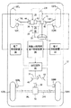
図1は電動式パワーステアリング装置を備えた後輪駆動車の制動制御装置の一部として構成された本発明による車輌用車輪状態推定装置の第一の実施形態を示す概略構成図である。
【0030】
図1に於いて、10FL及び10FRはそれぞれ車輌12の左右の前輪を示し、10RL及び10RRはそれぞれ車輌12の左右の後輪を示している。従動輪であり操舵輪でもある左右の前輪10FL及び10FRは運転者によるステアリングホイール14の転舵に応答して駆動されるラック・アンド・ピニオン式の電動式パワーステアリング装置16によりタイロッド18L及び18Rを介して操舵される。
【0031】
また図1に於いて、20は電子制御スロットルバルブ20Aを備えたエンジンを示しており、エンジン20の出力はエンジン用電子制御装置22により電子制御スロットルバルブ20Aが制御されることによって制御される。エンジン20の駆動力はトルクコンバータ24及びトランスミッション26を含む自動変速機28を介してプロペラシャフト30へ伝達され、プロペラシャフト30の駆動力はディファレンシャルギヤ装置32により左後輪車軸34L及び右後輪車軸34Rへ伝達され、これにより駆動輪である左右の後輪10RL及び10RRが回転駆動される。
【0032】
図示の実施形態に於いては、電動式パワーステアリング装置16はラック同軸型の電動式パワーステアリング装置であり、電子制御装置36により制御される。電動式パワーステアリング装置16は電動機38と、電動機38の回転トルクをラックバー40の往復動方向の力に変換する例えばボールねじ式の変換機構42とを有し、ハウジング44に対し相対的にラックバー40を駆動する補助転舵力を発生することにより、運転者の操舵負担を軽減する操舵アシストトルクを発生する。
【0033】
各車輪の制動力は制動装置46の油圧回路48によりホイールシリンダ50FL、50FR、50RL、50RRの制動圧が制御されることによって制御されるようになっている。図には示されていないが、油圧回路48はリザーバ、オイルポンプ、種々の弁装置等を含み、各ホイールシリンダの制動圧は通常時には運転者によるブレーキペダル52の踏み込み操作に応じて駆動されるマスタシリンダ54により制御され、また必要に応じて後に詳細に説明する如く電子制御装置56により制御される。
【0034】
車輪10FL〜10RRのホイールシリンダ50FL〜50RRにはそれぞれ対応するホイールシリンダ内の圧力Pi(i=fl、fr、rl、rr)を検出する圧力センサ60FL〜60RRが設けられ、マスタシリンダ54にはマスタシリンダ圧力Pmを検出する圧力センサ62が設けられている。またステアリングシャフト64にはそれぞれ操舵角θ及び操舵トルクTsを検出する操舵角センサ66及びトルクセンサ68が設けられ、車輌12にはそれぞれ車速V、車輌の前後加速度Gx、車輌の横加速度Gy、車輌のヨーレートγを検出する車速センサ70、前後加速度センサ72、横加速度センサ74、ヨーレートセンサ76が設けられている。尚操舵角センサ66、トルクセンサ68、横加速度センサ74、ヨーレートセンサ76は車輌の右旋回方向を正としてそれぞれ操舵角θ、操舵トルクTs、横加速度Gy、ヨーレートγを検出する。
【0035】
図2に示されている如く、圧力センサ60FL〜60RRにより検出されたホイールシリンダ50FL〜50RR内の圧力Piを示す信号、圧力センサ62により検出されたマスタシリンダ圧力Pmを示す信号、操舵角センサ66により検出された操舵角θを示す信号、車速センサ70により検出された車速Vを示す信号、前後加速度センサ72により検出された前後加速度Gxを示す信号、横加速度センサ74により検出された横加速度Gyを示す信号、ヨーレートセンサ76により検出されたヨーレートγを示す信号は電子制御装置56に入力される。
【0036】
図には示されていないが、エンジン20にはエンジン回転数Neを検出するエンジン回転数センサ78が設けられ、電子制御スロットルバルブ20Aにはスロットル開度φを検出するスロットル開度センサ80が設けられ、エンジン回転数Neを示す信号及びスロットル開度φを示す信号は図には示されていないアクセル開度センサよりのアクセル開度を示す信号や吸入空気量センサよりの吸入空気量を示す信号等と共にエンジン用電子制御装置22へ入力される。電子制御装置22はエンジン回転数Neを示す信号及びスロットル開度φを示す信号を電子制御装置56へ出力する。
【0037】
トルクセンサ68により検出された操舵トルクTsを示す信号は電子制御装置36に入力され、電子制御装置36には電子制御装置56より車速Vを示す信号も入力される。電子制御装置36は操舵トルクTsを示す信号と共に電動式パワーステアリング装置16に対するトルクアシスト指令電流Itaを示す信号を電子制御装置56へ出力する。
【0038】
尚図には詳細に示されていないが、電子制御装置22、36及び56はそれぞれ例えばCPUとROMとRAMと入出力ポート装置とを有し、これらが双方向性のコモンバスにより互いに接続された一般的な構成のマイクロコンピュータを含んでいる。
【0039】
特に図示の実施形態に於いては、電子制御装置56は、図3に示されたフローチャートに従い、前輪のグリップ度εfを演算すると共に前輪位置に於ける車輌の前後加速度Gxf及び横加速度Gyfを演算し、これらに基づき前輪の路面の摩擦係数μfを演算し、この値を路面の摩擦係数μとする。そして電子制御装置56は、左右後輪の前後力Fxr、横力Fyr、接地荷重Wrを演算し、路面の摩擦係数μ、左右後輪の前後力Fxr、横力Fyr、接地荷重Wrに基づき後輪のグリップ度εrを演算する。
【0040】
また電子制御装置56は、図4に示されたフローチャートに従い、車輌の非加速時であるか否かを判定し、車輌の非加速時にはエンジンブレーキ力Febを演算し、後輪のグリップ度εrに基づきエンジンブレーキが作用すると車輌の挙動が悪化する状況であるか否かを判定する。
【0041】
そして電子制御装置56は、エンジンブレーキが作用すると車輌の挙動が悪化する状況であるときには、マスタシリンダ圧力Pmに基づき車輌全体の目標摩擦制動力Fbvを演算し、エンジンブレーキ力Febと目標摩擦制動力Fbvとの和を車輌全体の目標制動力Fbvtとして、車輌の挙動を安定化させる配分にて車輌全体の目標制動力Fbvtを各車輪に配分することにより各車輪の目標制動力Fbti(i=fl、fr、rl、rr)を演算する。
【0042】
また電子制御装置56は、駆動輪である左右後輪の目標制動力Fbtrl及びFbtrrのうち小さい方の値に基づきエンジン20の目標出力トルクTet(負の値)を演算し、目標出力トルクTet及びエンジン回転数Neに基づき目標スロットル開度φtを演算し、目標スロットル開度φtを示す指令信号をエンジン用電子制御装置22へ出力する。
【0043】
更に電子制御装置56は、左右前輪の目標制動力Fbtfl及びFbtfrが達成されると共に左右後輪の目標制動力Fbtrl及びFbtrrのうち大きい方の値に対応する車輪の目標制動力Fbtrl又はFbtrrが達成されるよう、これらの車輪の制動圧Piを制御する。
【0044】
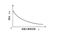
特に電子制御装置56は、路面の摩擦係数μが低いほど大きくなるよう閾値Keを演算し、後輪のグリップ度εrが閾値Keよりも小さいか否かの判別により、エンジンブレーキが作用すると車輌の挙動が悪化する状況であるか否かを判定する。
【0045】
電子制御装置36は、操舵トルクTsの大きさが大きいほどアシストトルクTabの大きさが大きくなり、車速Vが高いほどアシストトルクTabの大きさが小さくなるよう、操舵トルクTs及び車速Vに基づき図8に示されたグラフに対応すマップよりアシストトルクTabを演算し、少なくともアシストトルクTabに基づき電子制御装置36を介して電動式パワーステアリング装置16によるアシストトルクを制御し、これにより運転者の操舵負担を軽減する。尚電動式パワーステアリング装置16によるアシストトルクの制御自体は本発明の要旨をなすものではなく、当技術分野に於いて公知の任意の要領にて実行されてよい。
【0046】
電子制御装置22は通常時にはアクセル開度や吸入空気量等に基づいて電子制御スロットルバルブ20Aを制御することによりエンジン20の出力を制御するが、電子制御装置56より目標スロットル開度φtを示す指令信号が入力されると、該指令信号に従ってスロットル開度φが目標スロットル開度φtになるよう電子制御スロットルバルブ20Aを制御することによりエンジン20の出力トルクを制御する。尚通常時のエンジン20の制御も本発明の要旨をなすものではなく、当技術分野に於いて公知の任意の要領にて実行されてよい。
【0047】
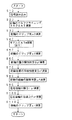
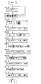
次に図3を参照して、路面の摩擦係数μ及び後輪のグリップ度εrの演算ルーチンについて説明する。尚図3に示されたフローチャートによる制御は図には示されていないイグニッションスイッチの閉成により開始され、所定の時間毎に繰返し実行される。
【0048】
まずステップ10に於いてはトルクセンサ68により検出された操舵トルクTsを示す信号等の読み込みが行われ、ステップ20に於いてはトルクアシスト指令電流Itaにトルク定数(正の定数)との積として電動式パワーステアリング装置16によるアシストトルクTasが演算され、トルクセンサ68により検出された操舵トルクTsとアシストトルクTasとの和より操舵系の摩擦力に対応する値を減算することにより、前輪のセルフアライニングトルクSATが演算される。尚前輪のセルフアライニングトルクSATは当技術分野に於いて公知の他の要領にて演算されてもよく、また検出されてもよい。
【0049】
ステップ30に於いては横加速度Gyと車速V及びヨーレートγの積V*γとの偏差Gy−V*γとして横加速度の偏差、即ち車輌の横すべり加速度Vydが演算され、この横加速度の偏差Vydが積分されることにより車体の横すべり速度Vyが演算されると共に、操舵角センサ66により検出された操舵角θより演算される前輪の実舵角θaが演算され、車体の横すべり速度Vy、前輪の実舵角θa、ヨーレートγ及び車速Vに基づき下記の式8に従って前輪のスリップ角αfが演算される。
αf=(Vy+Lf*γ)/V−θa ……(8)
【0050】
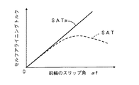
ステップ40に於いては前輪のスリップ角αfに基づき図5に示されたグラフに対応すマップ(実線)より車輌モデルのセルフアライニングトルクSATmが演算され、ステップ50に於いては前輪のセルフアライニングトルクSAT及び車輌モデルのセルフアライニングトルクSATmに基づき下記の式9に従って前輪のグリップ度εfが演算される。
εf=SAT/SATm ……(9)
【0051】
ステップ60に於いては横加速度Gy及びヨーレートγに基づき下記の式10に従って前輪位置に於ける車輌の横加速度Gyfが演算され、ステップ70に於いてはLf及びLrをそれぞれ重心と前輪車軸及び後輪車軸との間の距離として、前後加速度Gx及びヨーレートγに基づき下記の式11に従って前輪位置に於ける車輌の前後加速度Gxfが演算され、ステップ80に於いては下記の式12に従って前輪の路面の摩擦係数μfが演算され、この値が路面の摩擦係数μとされる。
【数9】
【数10】
ステップ90に於いては車輌のヨー慣性モーメントをIzとし、ヨーレートγの微分値をγdとし、車輌の重量をMとして、下記の式13に従って左右後輪の横力Fyrが演算され、ステップ100に於いては圧力−左右後輪制動力の変換係数Kbrとマスタシリンダ圧力Pmとの積として左右後輪の目標摩擦制動力Fbrtが演算されると共に、左右後輪の前後力Fxrがエンジンブレーキ力Febと左右後輪の目標摩擦制動力Fbrtとの和として演算される。
【数11】
ステップ110に於いては車輌の前後加速度Gxに基づき当技術分野に於いて公知の要領にて左右後輪の接地荷重Wrが演算されると共に、左右後輪の横力Fyr、左右後輪の前後力Fxr、路面の摩擦係数μ、左右後輪の接地荷重Wrに基づき下記の式14に従って後輪のグリップ度εrが演算される。
【数12】
次に図4に示されたフローチャートを参照して図示の第一の実施形態に於ける制動力制御ルーチンについて説明する。尚図4に示されたフローチャートによる制御も図には示されていないイグニッションスイッチの閉成により開始され、所定の時間毎に繰返し実行される。
【0055】
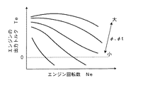
まずステップ210に於いては圧力センサ60FL〜60RRにより検出されたホイールシリンダ50FL〜50RR内の圧力Piを示す信号等の読み込みが行われ、ステップ220に於いては例えばスロットル開度φ及びエンジン回転数Neに基づき図6に示されたグラフに対応すマップより推定されるエンジン20の出力トルクTeが0以下であるか否かの判別により、車輌が非駆動状態にあるか否かの判別が行われ、否定判別が行われたときにはステップ300へ進み、肯定判別が行われたときにはステップ230へ進む。
【0056】
ステップ230に於いては路面の摩擦係数μが低いほど閾値Keが大きくなるよう、上述の図3に示されたフローチャートに従って演算された路面の摩擦係数μに基づき図7に示されたグラフに対応するマップより後述のステップ240の判別に供される閾値Keが演算される。
【0057】
ステップ240に於いては後輪のグリップ度εrが閾値Keよりも小さいか否かの判別、即ちエンジンブレーキ力Febが作用すると車輌の挙動が悪化する虞れがあるか否かの判別が行われ、否定判別が行われたときにはステップ300へ進み、肯定判別が行われたときにはステップ250へ進む。
【0058】
ステップ250に於いてはスロットル開度φ及びエンジン回転数Neに基づき図6に示されたグラフに対応すマップよりエンジン20の出力トルクTeが演算され、出力トルクTe及び駆動系のギヤ比に基づきエンジンブレーキ力Febが演算される。
【0059】
ステップ260に於いては圧力−車輌全体制動力の変換係数Kbv(正の値)とマスタシリンダ圧力Pmとの積として車輌全体の目標摩擦制動力Fbvが演算され、エンジンブレーキ力Febと目標摩擦制動力Fbvとの和として車輌全体の目標制動力Fbvtが演算される。また車輌の前後加速度Gx及び横加速度Gyに基づき当技術分野に於いて公知の要領にて各車輪の接地荷重Wi(i=fl、fr、rl、rr)が演算され、接地荷重Wiの和をWとして下記の式15に従って各車輪に対する目標制動力Fbvtの配分量、即ち各車輪の目標制動力Fbti(i=fl、fr、rl、rr)が演算される。
Fbti=Fbvt×Wi/W ……(15)
【0060】
ステップ270に於いては駆動輪である左右後輪の目標制動力Fbtrl及びFbtrrのうち小さい方の値をFbtrminとして、Fbtrminの2倍(目標エンジンブレーキ力Febt)及び駆動系のギヤ比に基づきエンジン20の目標出力トルクTet(負の値)が演算される。
【0061】
ステップ280に於いては左右前輪の目標制動力Fbtfl及びFbtfrに基づき左右前輪の目標制動圧Pbtfl及びPbtfrが演算され、左右前輪の制動圧Pfl及びPfrがそれぞれ目標制動圧Pbtfl及びPbtfrになるよう制御されると共に、左右後輪の目標制動力Fbtrl及びFbtrrのうち大きい方の値とFbtrminとの偏差ΔFbtrが演算され、偏差ΔFbtrに基づき目標制動圧Pbtrが演算され、当該車輪の制動圧が目標制動圧Pbtrになるよう制御される。
【0062】
ステップ290に於いては目標出力トルクTet及びエンジン回転数Neに基づき図6に示されたグラフに対応すマップより目標スロットル開度φtが演算され、目標スロットル開度φtを示す指令信号がエンジン用電子制御装置22へ出力され、しかる後ステップ10へ戻る。
【0063】
ステップ300に於いてはマスタシリンダ54とホイールシリンダ50FR、50FL、50RR、50RLとの連通が維持され、これにより各車輪の制動圧がマスタシリンダ圧力Pmにより制御される通常時の制動力制御が実行され、しかる後ステップ10へ戻る。
【0064】
かくして図示の第一の実施形態によれば、ステップ20に於いて前輪のセルフアライニングトルクSATが演算され、ステップ30に於いて前輪のスリップ角αfが演算され、ステップ40に於いて前輪のスリップ角αfに基づき車輌モデルのセルフアライニングトルクSATmが演算され、ステップ50に於いて前輪のセルフアライニングトルクSAT及び車輌モデルのセルフアライニングトルクSATmに基づき前輪のグリップ度εfが演算される。
【0065】
そしてステップ60〜100に於いてそれぞれ前輪位置に於ける車輌の横加速度Gyf、車輌の前後加速度Gxf、路面の摩擦係数μ、左右後輪の横力Fyr、左右後輪の前後力Fxrが演算され、ステップ110に於いて前輪のグリップ度εf、前輪の路面の摩擦係数μf、左右後輪の横力Fyr、左右後輪の前後力Fxrに基づき後輪のグリップ度εrが演算される。
【0066】
従って図示の第一の実施形態によれば、前後輪の路面の摩擦係数が同一であることを前提に、後輪のセルフアライニングトルクを検出することなく、推定される前輪のグリップ度εf及び路面の摩擦係数μを有効に利用して後輪のグリップ度εrを推定することができる。
【0067】
第二の実施形態
図9は本発明による車輌用車輪状態推定装置の第二の実施形態に於ける路面の摩擦係数μ及び後輪のグリップ度εrの演算ルーチンを示すゼネラルフローチャートである。尚図9に於いて図3に示されたステップと同一のステップには図3に於いて付されたステップ番号と同一のステップ番号が付されている。
【0068】
この実施形態に於いては、ステップ10の次に実行されるステップ15に於いて前輪が非制駆動状態にあるか否かの判別が行われ、否定判別が行われたときにはそのままステップ10へ戻り、肯定判別が行われたときにはステップ20へ進む。
【0069】
ステップ20〜60、80、100は上述の第一の実施形態の場合と同様に実行され、第一の実施形態のステップ70に対応するステップは実行されず、ステップ80の次に実行されるステップ95に於いて下記の式15に従って左右前輪の横力Fyfが演算される。
【数13】
ステップ120に於いては車輌の前後加速度Gx及び横加速度Gyに基づき当技術分野に於いて公知の要領にて左右前輪の接地荷重Wf及び左右後輪の接地荷重Wrが演算され、ステップ130に於いては前輪のグリップ度εf、路面の摩擦係数μ、左右前輪の横力Fyf、左右後輪の前後力Fxr、左右前輪の接地荷重Wf及び左右後輪の接地荷重Wrに基づき下記の式16に従って後輪のグリップ度εrが演算される。
【数14】
かくして図示の第二の実施形態によれば、ステップ20〜80に於いて上述の第一の実施形態の場合と同様の要領にて前輪のグリップ度εf及び路面の摩擦係数μが演算され、ステップ100に於いて左右後輪の前後力Fxrが演算されると共に、ステップ95に於いて左右前輪の横力Fyfが演算され、ステップ120に於いて左右前輪の接地荷重Wf及び左右後輪の接地荷重Wrが演算され、ステップ130に於いて前輪のグリップ度εf、路面の摩擦係数μ、左右前輪の横力Fyf、左右後輪の前後力Fxr、左右前輪の接地荷重Wf及び左右後輪の接地荷重Wrに基づき後輪のグリップ度εrが演算される。
【0072】
従って図示の第二の実施形態によれば、車輌の非制駆動時には前後輪のグリップ度が同一であることを前提に、上述の第一の実施形態の場合と同様、後輪のセルフアライニングトルクを検出することなく、推定される前輪のグリップ度εf及び路面の摩擦係数μを有効に利用して後輪のグリップ度εrを推定することができ、また後輪横力に比して位相が早い前輪横力を使用して後輪のグリップ度が推定されるので、後輪に制駆動力が作用したときの後輪のグリップ度を早く推定することができる。
【0073】
尚、上述の各実施形態によれば、車輌が非駆動状態にあるときにはステップ220に於いて肯定判別が行われ、ステップ230に於いて路面の摩擦係数μが低いほど閾値Keが大きくなるよう、路面の摩擦係数μに基づき閾値Keが演算される。
【0074】
そしてステップ240に於いて後輪のグリップ度εrが閾値Keよりも小さいか否かの判別により、エンジンブレーキ力Febが作用すると車輌の挙動が悪化する虞れがあるか否かの判別が行われ、車輌の挙動が悪化する虞れがあるときにはステップ250に於いてエンジンブレーキ力Febが演算され、ステップ260に於いてエンジンブレーキ力Febと目標摩擦制動力Fbvとの和として車輌全体の目標制動力Fbvtが演算されると共に、各車輪の接地荷重Wiに比例する割合にて車輌全体の目標制動力Fbvtが各車輪に配分されることにより各車輪の目標制動力Fbtiが演算される。
【0075】
ステップ270に於いて駆動輪である左右後輪の目標制動力Fbtrl及びFbtrrのうち小さい方の値をFbtrminとして、Fbtrminの2倍及び駆動系のギヤ比に基づきエンジン20の目標出力トルクTetが演算され、ステップ290に於いて目標出力トルクTet及びエンジン回転数Neに目標スロットル開度φtが演算され、目標スロットル開度φtを示す指令信号がエンジン用電子制御装置22へ出力される。
【0076】
更にステップ280に於いて左右前輪の目標制動力Fbtfl及びFbtfrに基づき左右前輪の目標制動圧Pbtfl及びPbtfrが演算され、左右前輪の制動圧Pfl及びPfrがそれぞれ目標制動圧Pbtfl及びPbtfrになるよう制御されると共に、左右後輪の目標制動力Fbtrl及びFbtrrのうち大きい方の値とFbtrminとの偏差ΔFbtrが演算され、偏差ΔFbtrに基づき目標制動圧Pbtrが演算され、当該車輪の制動圧が目標制動圧Pbtrになるよう制御される。
【0077】
一般に、車輌が前輪操舵式の後輪駆動車である場合に於いて、車輌が旋回限界に近づくと、前輪のセルフアライニングトルクが飽和した状態になり、前輪のセルフアライニングトルクは車輪の横力よりも早く飽和する。上述の各実施形態によれば、前輪のセルフアライニングトルクSATに基づいて後輪のグリップ度εrが演算され、後輪のグリップ度εrが閾値Keよりも小さいか否かの判別により、エンジンブレーキ力Febが作用すると車輌の挙動が悪化する虞れがあるか否かの判別が行われるので、エンジンブレーキが作用すると車輌の挙動が悪化する虞れがあるか否かを早期に判定し、これによりエンジンブレーキ力を早期に各車輪に配分して車輌の挙動の悪化を効果的に防止することができる。
【0078】
またステップ240に於いて否定判別が行われたときには、即ちエンジンブレーキ力Febが作用しても車輌の挙動が悪化する虞れがないときには、ステップ250〜290は実行されず、車輌が駆動状態にありステップ220に於いて否定判別が行われた場合と同様、ステップ300に於いてマスタシリンダ54とホイールシリンダ50FR、50FL、50RR、50RLとの連通が維持され、これにより各車輪の制動圧がマスタシリンダ圧力Pmにより制御される通常時の制動力制御が実行される。
【0079】
従ってエンジンブレーキ力Febが作用すると車輌の挙動が悪化する虞れがある場合にのみ、ステップ250〜290が実行され、車輌の挙動が安定化させる配分比率にてエンジンブレーキ力Febが各車輪に配分されるので、車輌の挙動が悪化する虞れがあるか否かが考慮されることなくエンジンブレーキ力が各車輪に配分される従来の制動力制御装置の場合に比して、非駆動輪である左右前輪及び左右後輪のうち配分されたエンジンブレーキ力が大きい側の車輪の制動装置の負担、例えば山道降坂時の制動装置の作動頻度及び作動時間を軽減し、その耐久性を向上させることができる。
【0080】
更に上述の各実施形態によれば、ステップ230に於いて路面の摩擦係数μが低いほど閾値Keが大きくなるよう、路面の摩擦係数μに基づき閾値Keが演算され、後輪のグリップ度εrが閾値Keよりも小さいか否かの判別により、エンジンブレーキ力Febが作用すると車輌の挙動が悪化する虞れがあるか否かの判別が行われるので、路面の摩擦係数μが低いほど、即ち車輌の挙動が悪化し易いほど早期に車輌の挙動が悪化する虞れがあると判定することができ、これにより応答遅れなく車輌の挙動の悪化を効果的に防止することができる。
【0081】
以上に於いては本発明を特定の実施形態について詳細に説明したが、本発明は上述の実施形態に限定されるものではなく、本発明の範囲内にて他の種々の実施形態が可能であることは当業者にとって明らかであろう。
【0082】
例えば上述の各実施形態に於いては、前輪のセルフアライニングトルクSAT及びスリップ角αfが演算され、前輪のスリップ角αfに基づき車輌モデルのセルフアライニングトルクSATmが演算され、前輪のセルフアライニングトルクSAT及び車輌モデルのセルフアライニングトルクSATmに基づき前輪のグリップ度εfが演算されるようになっているが、前輪のグリップ度εfは当技術分野に於いて公知の任意の要領にて演算されてよい。
【0083】
また上述の各実施形態に於いては、後輪のグリップ度εrが閾値Keよりも小さいか否かの判別により、エンジンブレーキ力Febが作用すると車輌の挙動が悪化する虞れがあるか否かの判別が行われ、その判別結果に基づき各車輪の制動力が制御されるようになっているが、後輪のグリップ度εrは例えば後輪駆動車のトラクション制御や四輪駆動車の後輪駆動力の制御の如く、車輌の任意の制御に使用されてよい。
【0084】
更に上述の各実施形態に於いては、車輌は後輪駆動車であるが、本発明は四輪駆動車に適用されてもよい。
【図面の簡単な説明】
【図1】電動式パワーステアリング装置を備えた後輪駆動車の制動制御装置の一部として構成された本発明による車輌用車輪状態推定装置の第一の実施形態を示す概略構成図である。
【図2】第一の実施形態に於ける制御系を示すブロック図である。
【図3】第一の実施形態に於ける路面の摩擦係数μ及び後輪のグリップ度εr演算ルーチンを示すフローチャートである。
【図4】第一の実施形態に於ける制動力制御ルーチンを示すフローチャートである。
【図5】前輪のスリップ角αfと車輌モデルのSAT(実線)及び実際のSATの一例(破線)との間の関係を示すグラフである。
【図6】エンジン回転数Neとスロットル開度φと及びエンジンの出力トルクTe及び目標出力トルクTetとの間の関係を示すグラフである。
【図7】路面の摩擦係数μと閾値Keとの間の関係を示すグラフである。
【図8】操舵トルクTs及び車速VとアシストトルクTabとの間の関係を示すグラフである。
【図9】本発明による車輌用車輪状態推定装置の第二の実施形態に於ける路面の摩擦係数μ及び後輪のグリップ度εr演算ルーチンを示すフローチャートである。
【符号の説明】
16…電動式パワーステアリング装置16
20…エンジン
22、36…電子制御装置
46…制動装置
54…マスタシリンダ
56…電子制御装置
60FL〜60RR、62…圧力センサ
66…操舵角センサ
68…トルクセンサ
70…車速センサ
72…前後加速度センサ
74…横加速度センサ
76…ヨーレートセンサ[0001]
TECHNICAL FIELD OF THE INVENTION
The present invention relates to a vehicle wheel state estimating apparatus, and more particularly, to a vehicle wheel state estimating apparatus for estimating a rear wheel grip degree.
[0002]
[Prior art]
As one of the wheel state estimating devices for vehicles such as automobiles, for example, as described in Patent Document 1 below filed by the present applicant, self-aligning torque of front wheels that are steered wheels is calculated, and 2. Description of the Related Art A road surface friction coefficient detection device that calculates a front wheel cornering force based on a time differential value of a yaw rate and a lateral acceleration of a vehicle and calculates a road surface friction coefficient based on a self-aligning torque and a cornering force is conventionally known.
[Patent Document 1]
JP-A-6-221968
[0003]
[Problems to be solved by the invention]
According to the road surface friction coefficient detecting device as described above, the road surface friction coefficient can be estimated, so that the front wheel grip degree can be calculated based on the self-aligning torque and the road surface friction coefficient, and the front wheel grip degree can be calculated. , The braking / driving force of the front wheels can be appropriately controlled, but in order to properly control the braking / driving force of the rear wheels, it is desirable that the grip of the rear wheels is also estimated.
[0004]
As in the case of the front wheels, if the self-aligning torque of the rear wheels is detected, the grip of the rear wheels can be calculated based on the self-aligning torque of the rear wheels and the friction coefficient of the road surface. In order to detect the self-aligning torque of the rear wheels, a force sensor or the like is required, and there is a problem that the wheel state estimating device must be expensive.
[0005]
The present invention has been made in view of the technical requirement that the grip of the rear wheel needs to be estimated at low cost in order to properly control the braking / driving force of the rear wheel. The problem is to estimate the degree of grip of the rear wheels without detecting the self-aligning torque of the rear wheels by estimating the self-aligning torque of the front wheels and the friction coefficient of the road surface and effectively using these.
[0006]
[Means for Solving the Problems]
According to the present invention, the main problem described above is to calculate the degree of grip of the front wheels based on the self-aligning torque of the front wheels that are the steered wheels, calculate the coefficient of friction of the road surface based on the degree of grip of the front wheels, A vehicle wheel state estimating device for estimating a degree of grip of a rear wheel based on a friction coefficient and a front-rear force and a lateral force of a rear wheel; The front wheel grip degree is calculated based on the self-aligning torque of the front wheel, which is the steered wheel, and the grip force of the front wheel, the front-rear force of the rear wheel, the lateral force of the front wheel, and the contact load of the front wheel and the rear wheel in a situation where the steering wheel is not in operation. Based on the above, the grip degree of the rear wheel in a situation where the braking / driving force acts on the rear wheel is estimated by the vehicle wheel state estimating device (the configuration of claim 2).
[0007]
Further, according to the present invention, in order to effectively achieve the above-mentioned main problem, in the configuration of the second aspect, the grip degree of the front wheel is set to εf, the front-rear force of the rear wheel is set to Fxr, Assuming that the force is Fyf, the ground load of the front wheel and the rear wheel is Wf and Wr, respectively, and α = (FxrWf) / (FyfWr),
(Equation 2)
![]()
[0008]
In this specification, the "grip degree" refers to a difference between a force in a direction along a road surface where a wheel can be generated and a force in a direction along a road surface where a wheel is generated, on a road surface where a wheel can be generated. The value (ε) divided by the force along the road surface, and the value obtained by dividing the force along the road surface where the wheels are generated by the force along the road surface where the wheels can be generated is called μ utilization factor Then, the grip factor ε is equal to “1-μ utilization factor”.
[0009]
Function and effect of the present invention
In general, the grip of the rear wheel can be estimated based on the front-rear force of the rear wheel, the lateral force of the rear wheel, and the coefficient of friction of the road surface.The grip of the front wheel is determined based on the self-aligning torque of the front wheel, which is the steering wheel. Since the friction coefficient of the road surface of the front wheel can be estimated based on the degree of grip of the front wheel, it is possible to estimate the friction coefficient of the road surface of the front and rear wheels based on the self-aligning torque of the front wheel. By estimating the degree of grip of the front wheels and estimating the friction coefficient of the road surface based on the degree of grip of the front wheels, the degree of grip of the rear wheels is determined based on the front-rear force of the rear wheels, the lateral force of the rear wheels, and the friction coefficient of the road surface. Can be estimated.
[0010]
According to the configuration of the first aspect, the grip degree of the front wheel is calculated based on the self-aligning torque of the front wheel that is the steered wheel, the friction coefficient of the road surface is calculated based on the grip degree of the front wheel, and the front-rear force of the rear wheel is calculated. Since the grip of the rear wheel is estimated based on the lateral force of the rear wheel and the friction coefficient of the road surface, the self-aligning torque of the rear wheel is detected on the assumption that the friction coefficient of the front and rear wheels is the same. The degree of grip of the rear wheel can be estimated without any need.
[0011]
Generally, when it is assumed that the front and rear wheels have the same grip when the vehicle is not in the braking / driving state, as will be described in detail later, the self-aligning of the front wheels in a situation where no braking / driving force is generated in the front wheels. By calculating the grip of the front wheels based on the torque, the braking / driving force acts on the rear wheels based on the grip of the front wheels, the front and rear forces of the rear wheels, the lateral forces of the front wheels, and the grounding loads of the front and rear wheels. It is possible to estimate the degree of grip of the rear wheel at the time.
[0012]
According to the configuration of the second aspect, the grip degree of the front wheel is calculated based on the self-aligning torque of the front wheel which is the steered wheel in a situation where the braking / driving force is not generated on the front wheel, and the grip degree of the front wheel and the rear wheel are calculated. The degree of grip of the rear wheels in a situation where the braking / driving force acts on the rear wheels based on the front-rear force of the wheels, the lateral force of the front wheels, and the ground load of the front wheels and the rear wheels is estimated. Assuming that the front and rear wheels have the same grip, it is possible to estimate the rear wheel grip in a situation where the braking / driving force acts on the rear wheels without detecting the rear wheel self-aligning torque. .
[0013]
The fact that the front and rear wheels have the same grip means that the ratio of the lateral force of the front and rear wheels is equal to the ratio of the ground load of the front and rear wheels. In general, the generation of the lateral force of the rear wheel is later than the generation of the lateral force of the front wheel. However, according to the configuration of the second aspect, it is assumed that the grip degree of the front and rear wheels is the same, so that the phase is earlier. Since the front wheel lateral force can be used, it is possible to quickly estimate the grip of the rear wheel when the braking / driving force acts on the rear wheel.
[0014]
As described above, when it is assumed that the grip degree εf of the front wheels and the grip degree εr of the rear wheels are the same when the vehicle is not in the braking / driving state, the friction coefficient of the road surface is μ, the ground contact load of the rear wheels is Wr, and the rear wheels are Assuming that the lateral force is Fyr, the following equation 2 is established.
(Equation 3)
When the braking / driving force acts on the rear wheels in a situation where the vehicle is not in the braking / driving state, the grip εr of the rear wheels is expressed by the following equation 3.
(Equation 4)
From the above equation (2), μWr is expressed by the following equation (4). If this equation (4) is substituted into the equation (3) and α is expressed by the following equation (5), the grip degree εr of the rear wheel is expressed by the above equation (1). Therefore, the gripping degree εr of the rear wheel in the situation where the braking / driving force acts on the rear wheel can be calculated by the above equation (1).
(Equation 5)
According to the configuration of the third aspect, the grip degree of the rear wheel is estimated according to the above equation 1, so that the braking / driving force acts on the rear wheel without detecting the self-aligning torque of the rear wheel. It is possible to accurately estimate the degree of grip of the rear wheel to be driven.
[0018]
Preferred embodiments of the means for solving the problems
According to one preferred aspect of the present invention, in the configuration of the first aspect, the self-aligning torque SAT of the front wheel is calculated, the slip angle of the front wheel is calculated, and the self-alignment torque of the vehicle model is calculated based on the slip angle of the front wheel. The configuration is such that the aligning torque SATm is calculated, and the grip degree of the front wheels is calculated as a ratio of the self-aligning torque SAT of the front wheels to the self-aligning torque SATm of the vehicle model (preferred mode 1).
[0019]
According to another preferred aspect of the present invention, in the configuration of the first aspect, the friction of the road surface of the front wheel based on the grip degree εf of the front wheel, the longitudinal acceleration Gxf and the lateral acceleration Gyf of the vehicle at the front wheel position. The coefficient μf is calculated, and the friction coefficient μf of the road surface of the front wheel is set as the friction coefficient μ of the road surface (preferred mode 2).
[0020]
According to another preferred aspect of the present invention, in the configuration of claim 1, the front-rear force Fxr and the lateral force Fyr of the rear wheel are estimated, the ground contact load Wr of the rear wheel is estimated, and the road surface friction is estimated. The rear wheel grip degree εr is estimated based on the coefficient μ, the front-rear force Fxr and the lateral force Fyr of the rear wheel, and the ground contact load Wr of the rear wheel (preferred mode 3).
[0021]
According to another preferred embodiment of the present invention, in the configuration of the preferred embodiment 2, the following formula 6
(Equation 7)
[0022]
According to another preferred embodiment of the present invention, in the configuration of the preferred embodiment 3, the following formula 7
(Equation 8)
[0023]
According to another preferred aspect of the present invention, in the configuration of the second aspect, the degree of grip of the front wheel is calculated based on the self-aligning torque of the front wheel when the vehicle is not driven (preferred aspect). 6).
[0024]
According to another preferred aspect of the present invention, in the configuration of claim 2, the front-rear force of the rear wheel, the lateral force of the front wheel, the ground contact load of the front wheel and the rear wheel are estimated, and the grip degree of the front wheel and It is configured to estimate the degree of grip of the rear wheel in a situation where braking / driving force acts on the rear wheel based on the front-rear force of the rear wheel, the lateral force of the front wheel, and the grounding load of the front wheel and the rear wheel (preferred mode 7 ).
[0025]
According to another preferred embodiment of the present invention, in the configuration of claim 1 or 2, the vehicle is a rear-wheel drive vehicle or a four-wheel drive vehicle in which a rear wheel is driven by an engine. The longitudinal force is configured to be calculated as the sum of the engine braking force and the friction braking force of the rear wheels (preferred mode 8).
[0026]
According to another preferred aspect of the present invention, in the configuration of the first aspect, the lateral force of the rear wheel is calculated based on the lateral acceleration and the yaw rate of the vehicle (preferred aspect 9). .
[0027]
According to another preferred aspect of the present invention, in the configuration of the second aspect, the lateral force of the front wheel is calculated based on the lateral acceleration and the yaw rate of the vehicle (preferred aspect 10).
[0028]
BEST MODE FOR CARRYING OUT THE INVENTION
Hereinafter, the present invention will be described in detail with reference to the accompanying drawings with reference to some preferred embodiments (hereinafter simply referred to as embodiments).
[0029]
First embodiment
FIG. 1 is a schematic configuration diagram showing a first embodiment of a vehicle wheel state estimating device according to the present invention, which is configured as a part of a braking control device for a rear wheel drive vehicle including an electric power steering device.
[0030]
1, 10FL and 10FR indicate left and right front wheels of the
[0031]
In FIG. 1,
[0032]
In the illustrated embodiment, the electric
[0033]
The braking force of each wheel is controlled by controlling the braking pressure of the wheel cylinders 50FL, 50FR, 50RL, 50RR by the
[0034]
Wheel cylinders 50FL to 50RR of wheels 10FL to 10RR are provided with pressure sensors 60FL to 60RR for detecting pressures Pi (i = fl, fr, rl, rr) in the corresponding wheel cylinders, respectively. A pressure sensor 62 for detecting the cylinder pressure Pm is provided. The steering shaft 64 is provided with a
[0035]
As shown in FIG. 2, a signal indicating the pressure Pi in the wheel cylinders 50FL to 50RR detected by the pressure sensors 60FL to 60RR, a signal indicating the master cylinder pressure Pm detected by the pressure sensor 62, a
[0036]
Although not shown, the
[0037]
A signal indicating the steering torque Ts detected by the
[0038]
Although not shown in detail in the figure, the
[0039]
In particular, in the illustrated embodiment, the electronic control unit 56 calculates the front wheel grip degree εf and calculates the longitudinal acceleration Gxf and the lateral acceleration Gyf of the vehicle at the front wheel position in accordance with the flowchart shown in FIG. Then, a friction coefficient μf of the road surface of the front wheel is calculated based on these, and this value is set as a friction coefficient μ of the road surface. Then, the electronic control unit 56 calculates the front-rear force Fxr, the lateral force Fyr, and the ground contact load Wr of the left and right rear wheels, and calculates the rearward based on the road surface friction coefficient μ, the front-rear force Fxr of the left and right rear wheels, the lateral force Fyr, and the contact load Wr. The wheel grip degree εr is calculated.
[0040]
Further, the electronic control unit 56 determines whether or not the vehicle is not accelerating according to the flowchart shown in FIG. 4, calculates the engine braking force Feb when the vehicle is not accelerating, and calculates the rear wheel grip degree εr. Then, it is determined whether or not the vehicle is degraded when the engine brake is applied.
[0041]
The electronic control unit 56 calculates the target frictional braking force Fbv of the whole vehicle based on the master cylinder pressure Pm when the behavior of the vehicle is deteriorated when the engine brake is applied, and the engine braking force Feb and the target frictional braking force are calculated. Fbv is set as the target braking force Fbvt of the entire vehicle, and the target braking force Fbvt of each wheel is distributed to each wheel in a distribution that stabilizes the behavior of the vehicle. , Fr, rl, rr).
[0042]
Further, the electronic control unit 56 calculates a target output torque Tet (negative value) of the
[0043]
Further, the electronic control unit 56 achieves the target braking forces Fbtfl and Fbtfr of the left and right front wheels and the target braking forces Fbtrl or Fbtrr of the wheels corresponding to the larger of the target braking forces Fbtrl and Fbtrr of the left and right rear wheels. To control the braking pressure Pi of these wheels.
[0044]
In particular, the electronic control unit 56 calculates the threshold value Ke so as to increase as the friction coefficient μ of the road surface decreases, and determines whether the grip degree εr of the rear wheel is smaller than the threshold value Ke. It is determined whether the situation is such that the behavior deteriorates.
[0045]
The
[0046]
Normally, the
[0047]
Next, a routine for calculating the road surface friction coefficient μ and the rear wheel grip degree εr will be described with reference to FIG. The control according to the flowchart shown in FIG. 3 is started by closing an ignition switch (not shown) and is repeatedly executed at predetermined time intervals.
[0048]
First, in
[0049]
In
αf = (Vy + Lf * γ) / V−θa (8)
[0050]
In
εf = SAT / SATm (9)
[0051]
In
(Equation 9)
(Equation 10)
In
(Equation 11)
In step 110, the ground load Wr of the left and right rear wheels is calculated based on the longitudinal acceleration Gx of the vehicle in a manner known in the art, the lateral force Fyr of the left and right rear wheels, and the front and rear of the left and right rear wheels. Based on the force Fxr, the coefficient of friction μ of the road surface, and the ground contact load Wr of the left and right rear wheels, the grip degree εr of the rear wheels is calculated according to the following
(Equation 12)
Next, a braking force control routine in the illustrated first embodiment will be described with reference to the flowchart shown in FIG. The control according to the flowchart shown in FIG. 4 is also started by closing an ignition switch (not shown) and is repeatedly executed at predetermined time intervals.
[0055]
First, in step 210, a signal indicating the pressure Pi in the wheel cylinders 50FL to 50RR detected by the pressure sensors 60FL to 60RR is read, and in
[0056]
In
[0057]
In
[0058]
In
[0059]
In
Fbti = Fbvt × Wi / W (15)
[0060]
In
[0061]
In step 280, the target braking pressures Pbtfl and Pbtfr of the left and right front wheels are calculated based on the target braking forces Fbtfl and Fbtfr of the left and right front wheels, and control is performed so that the braking pressures Pfl and Pfr of the left and right front wheels become the target braking pressures Pbtfl and Pbtfr, respectively. At the same time, a difference ΔFbtr between the larger value of the target braking forces Fbtrl and Fbtrr of the left and right rear wheels and Fbtrmin is calculated, a target braking pressure Pbtr is calculated based on the difference ΔFbtr, and the braking pressure of the wheels is set to the target braking pressure. The pressure is controlled to be Pbtr.
[0062]
In step 290, the target throttle opening φt is calculated from the map corresponding to the graph shown in FIG. 6 based on the target output torque Tet and the engine speed Ne, and a command signal indicating the target throttle opening φt is output to the engine. It is output to the
[0063]
In
[0064]
Thus, according to the first embodiment shown in the figure, the self-aligning torque SAT of the front wheels is calculated in
[0065]
In
[0066]
Therefore, according to the illustrated first embodiment, on the assumption that the friction coefficients of the road surfaces of the front and rear wheels are the same, without detecting the self-aligning torque of the rear wheels, the estimated grip degree εf of the front wheels and The grip degree εr of the rear wheel can be estimated by effectively using the friction coefficient μ of the road surface.
[0067]
Second embodiment
FIG. 9 is a general flowchart showing a calculation routine of the road surface friction coefficient μ and the rear wheel grip degree εr in the second embodiment of the vehicle wheel state estimation device according to the present invention. In FIG. 9, the same steps as those shown in FIG. 3 are assigned the same step numbers as those given in FIG.
[0068]
In this embodiment, in
[0069]
(Equation 13)
In
[Equation 14]
Thus, according to the illustrated second embodiment, in
[0072]
Therefore, according to the illustrated second embodiment, the self-alignment of the rear wheels is performed in the same manner as in the above-described first embodiment, on the assumption that the grip of the front and rear wheels is the same when the vehicle is not driven. Without detecting the torque, the grip degree εr of the rear wheel can be estimated by effectively using the estimated grip degree εf of the front wheel and the friction coefficient μ of the road surface. Is used to estimate the degree of grip of the rear wheel using the front wheel lateral force, which makes it possible to quickly estimate the degree of grip of the rear wheel when braking / driving force acts on the rear wheel.
[0073]
According to the above-described embodiments, when the vehicle is in the non-driving state, an affirmative determination is made in
[0074]
Then, in
[0075]
In
[0076]
Further, in step 280, target braking pressures Pbtfl and Pbtfr for the left and right front wheels are calculated based on the target braking forces Fbtfl and Fbtfr for the left and right front wheels, and control is performed so that the braking pressures Pfl and Pfr for the left and right front wheels become the target braking pressures Pbtfl and Pbtfr, respectively. At the same time, a difference ΔFbtr between the larger value of the target braking forces Fbtrl and Fbtrr of the left and right rear wheels and Fbtrmin is calculated, a target braking pressure Pbtr is calculated based on the difference ΔFbtr, and the braking pressure of the wheels is set to the target braking pressure. The pressure is controlled to be Pbtr.
[0077]
In general, when the vehicle is a front-wheel steering rear-wheel drive vehicle, when the vehicle approaches the turning limit, the self-aligning torque of the front wheels becomes saturated, and the self-aligning torque of the front wheels is Saturates faster than force. According to each of the above-described embodiments, the grip degree εr of the rear wheel is calculated based on the self-aligning torque SAT of the front wheel, and the engine brake is determined by determining whether the grip degree εr of the rear wheel is smaller than the threshold Ke. Since it is determined whether or not the behavior of the vehicle is likely to deteriorate when the force Feb acts, it is determined at an early stage whether or not the behavior of the vehicle may deteriorate when the engine brake acts. As a result, the engine braking force can be distributed to the respective wheels at an early stage, and the behavior of the vehicle can be effectively prevented from deteriorating.
[0078]
When a negative determination is made in
[0079]
Therefore, only when there is a possibility that the behavior of the vehicle will deteriorate when the engine braking force Feb acts,
[0080]
Further, according to each of the above-described embodiments, the threshold value Ke is calculated based on the road surface friction coefficient μ so that the lower the road surface friction coefficient μ is, the larger the threshold value Ke is in
[0081]
In the above, the present invention has been described in detail with respect to a specific embodiment. However, the present invention is not limited to the above embodiment, and various other embodiments are possible within the scope of the present invention. Some will be apparent to those skilled in the art.
[0082]
For example, in each of the above-described embodiments, the self-aligning torque SAT and the slip angle αf of the front wheels are calculated, and the self-aligning torque SATm of the vehicle model is calculated based on the slip angle αf of the front wheels. The grip εf of the front wheels is calculated based on the torque SAT and the self-aligning torque SATm of the vehicle model. The grip εf of the front wheels is calculated in any manner known in the art. May be.
[0083]
Further, in each of the above-described embodiments, it is determined whether or not the behavior of the vehicle may be degraded when the engine braking force Feb acts by determining whether or not the grip degree εr of the rear wheel is smaller than the threshold Ke. Is determined, and the braking force of each wheel is controlled based on the determination result. The grip degree εr of the rear wheel is, for example, the traction control of the rear wheel drive vehicle or the rear wheel of the four wheel drive vehicle. It may be used for any control of the vehicle, such as control of the driving force.
[0084]
Further, in each of the above embodiments, the vehicle is a rear wheel drive vehicle, but the present invention may be applied to a four wheel drive vehicle.
[Brief description of the drawings]
FIG. 1 is a schematic configuration diagram showing a first embodiment of a vehicle wheel state estimation device according to the present invention, which is configured as a part of a braking control device for a rear wheel drive vehicle including an electric power steering device.
FIG. 2 is a block diagram illustrating a control system according to the first embodiment.
FIG. 3 is a flowchart showing a routine for calculating a friction coefficient μ of a road surface and a grip degree εr of a rear wheel in the first embodiment.
FIG. 4 is a flowchart illustrating a braking force control routine according to the first embodiment.
FIG. 5 is a graph showing a relationship between a front wheel slip angle αf and a SAT (solid line) of a vehicle model and an example of an actual SAT (broken line).
FIG. 6 is a graph showing a relationship between an engine speed Ne, a throttle opening φ, and an engine output torque Te and a target output torque Tet.
FIG. 7 is a graph showing a relationship between a friction coefficient μ of a road surface and a threshold value Ke.
FIG. 8 is a graph showing a relationship between a steering torque Ts, a vehicle speed V, and an assist torque Tab.
FIG. 9 is a flowchart showing a routine for calculating a road surface friction coefficient μ and a rear wheel grip degree εr in a second embodiment of the vehicle wheel state estimation device according to the present invention.
[Explanation of symbols]
16: Electric
20 ... Engine
22, 36 ... Electronic control device
46 ... Brake device
54… Master cylinder
56 ... Electronic control device
60FL-60RR, 62 ... Pressure sensor
66 ... Steering angle sensor
68 ... Torque sensor
70 ... Vehicle speed sensor
72 ... longitudinal acceleration sensor
74 ... lateral acceleration sensor
76 ... Yaw rate sensor
Claims (3)
Priority Applications (1)
| Application Number | Priority Date | Filing Date | Title |
|---|---|---|---|
| JP2003020637A JP4158539B2 (en) | 2003-01-29 | 2003-01-29 | Vehicle wheel state estimation device |
Applications Claiming Priority (1)
| Application Number | Priority Date | Filing Date | Title |
|---|---|---|---|
| JP2003020637A JP4158539B2 (en) | 2003-01-29 | 2003-01-29 | Vehicle wheel state estimation device |
Publications (2)
| Publication Number | Publication Date |
|---|---|
| JP2004231004A true JP2004231004A (en) | 2004-08-19 |
| JP4158539B2 JP4158539B2 (en) | 2008-10-01 |
Family
ID=32950214
Family Applications (1)
| Application Number | Title | Priority Date | Filing Date |
|---|---|---|---|
| JP2003020637A Expired - Fee Related JP4158539B2 (en) | 2003-01-29 | 2003-01-29 | Vehicle wheel state estimation device |
Country Status (1)
| Country | Link |
|---|---|
| JP (1) | JP4158539B2 (en) |
Cited By (7)
| Publication number | Priority date | Publication date | Assignee | Title |
|---|---|---|---|---|
| JP2007223389A (en) * | 2006-02-22 | 2007-09-06 | Nissan Motor Co Ltd | Device for state estimation and control of vehicle |
| JP2007223388A (en) * | 2006-02-22 | 2007-09-06 | Nissan Motor Co Ltd | Device for state estimation and control of vehicle |
| JP2009143371A (en) * | 2007-12-13 | 2009-07-02 | Nsk Ltd | Electric power steering device |
| JP2009143452A (en) * | 2007-12-14 | 2009-07-02 | Nsk Ltd | Vehicle travel control device |
| CN106143210A (en) * | 2015-05-13 | 2016-11-23 | 丰田自动车株式会社 | The driving-force control apparatus of four-wheel drive vehicle |
| CN106547970A (en) * | 2016-10-27 | 2017-03-29 | 西安航空制动科技有限公司 | According to the method that wheel side force determines drag friction coefficient |
| CN110395199A (en) * | 2018-04-24 | 2019-11-01 | 通用汽车环球科技运作有限责任公司 | Detect the device and method of wheel alignment situation |
-
2003
- 2003-01-29 JP JP2003020637A patent/JP4158539B2/en not_active Expired - Fee Related
Cited By (9)
| Publication number | Priority date | Publication date | Assignee | Title |
|---|---|---|---|---|
| JP2007223389A (en) * | 2006-02-22 | 2007-09-06 | Nissan Motor Co Ltd | Device for state estimation and control of vehicle |
| JP2007223388A (en) * | 2006-02-22 | 2007-09-06 | Nissan Motor Co Ltd | Device for state estimation and control of vehicle |
| JP2009143371A (en) * | 2007-12-13 | 2009-07-02 | Nsk Ltd | Electric power steering device |
| JP2009143452A (en) * | 2007-12-14 | 2009-07-02 | Nsk Ltd | Vehicle travel control device |
| CN106143210A (en) * | 2015-05-13 | 2016-11-23 | 丰田自动车株式会社 | The driving-force control apparatus of four-wheel drive vehicle |
| CN106143210B (en) * | 2015-05-13 | 2018-05-01 | 丰田自动车株式会社 | The driving-force control apparatus of four-wheel drive vehicle |
| CN106547970A (en) * | 2016-10-27 | 2017-03-29 | 西安航空制动科技有限公司 | According to the method that wheel side force determines drag friction coefficient |
| CN106547970B (en) * | 2016-10-27 | 2019-05-07 | 西安航空制动科技有限公司 | The method for determining drag friction coefficient according to wheel lateral force |
| CN110395199A (en) * | 2018-04-24 | 2019-11-01 | 通用汽车环球科技运作有限责任公司 | Detect the device and method of wheel alignment situation |
Also Published As
| Publication number | Publication date |
|---|---|
| JP4158539B2 (en) | 2008-10-01 |
Similar Documents
| Publication | Publication Date | Title |
|---|---|---|
| JP4029856B2 (en) | Vehicle behavior control device | |
| JP3937524B2 (en) | Vehicle braking / driving force control device | |
| EP1270305B1 (en) | Driving force controlling apparatus and method for four-wheel drive vehicle | |
| US8655563B2 (en) | Braking/driving force controller of vehicle | |
| US8116942B2 (en) | Steering angle control apparatus for vehicle | |
| EP1424263A2 (en) | Vehicle steering control device | |
| US20050096830A1 (en) | Integrated control apparatus for vehicle | |
| CN109720338B (en) | Vehicle behavior control device | |
| JP2002127772A (en) | Power distribution control device of four-wheel drive vehicle | |
| JPH1159216A (en) | Power distributing control device for four-wheel drive vehicle | |
| JPH0729557B2 (en) | Drive force distribution controller for four-wheel drive vehicle | |
| JP4501343B2 (en) | Braking force control device for vehicle | |
| JP3607985B2 (en) | Vehicle body speed estimation device and control device | |
| JP2007186020A (en) | Motion controller for vehicle | |
| JP2004106649A (en) | Power distribution controller of four-wheel drive vehicle | |
| JP2007106338A (en) | Vehicle body speed estimating device for vehicle | |
| JP4158539B2 (en) | Vehicle wheel state estimation device | |
| JP4114065B2 (en) | Four-wheel drive vehicle behavior control device | |
| US10604010B2 (en) | Behavior control device for four-wheel drive vehicle | |
| JP3948076B2 (en) | Estimation method of friction circle radius of wheel | |
| US20030173129A1 (en) | Stability control throttle compensation on vehicles with passive all wheel drive systems | |
| JP4055225B2 (en) | Vehicle braking / driving force control device | |
| JP3518464B2 (en) | Driving force distribution control device for four-wheel drive vehicle | |
| JP4661450B2 (en) | Vehicle drive torque control device | |
| JP4685407B2 (en) | Vehicle behavior control device |
Legal Events
| Date | Code | Title | Description |
|---|---|---|---|
| RD02 | Notification of acceptance of power of attorney |
Free format text: JAPANESE INTERMEDIATE CODE: A7422 Effective date: 20051226 |
|
| RD04 | Notification of resignation of power of attorney |
Free format text: JAPANESE INTERMEDIATE CODE: A7424 Effective date: 20051227 |
|
| A711 | Notification of change in applicant |
Free format text: JAPANESE INTERMEDIATE CODE: A711 Effective date: 20060119 |
|
| A621 | Written request for application examination |
Free format text: JAPANESE INTERMEDIATE CODE: A621 Effective date: 20060120 |
|
| A521 | Written amendment |
Free format text: JAPANESE INTERMEDIATE CODE: A821 Effective date: 20060119 |
|
| RD02 | Notification of acceptance of power of attorney |
Free format text: JAPANESE INTERMEDIATE CODE: A7422 Effective date: 20060419 |
|
| A521 | Written amendment |
Free format text: JAPANESE INTERMEDIATE CODE: A821 Effective date: 20060420 |
|
| A977 | Report on retrieval |
Free format text: JAPANESE INTERMEDIATE CODE: A971007 Effective date: 20070727 |
|
| A131 | Notification of reasons for refusal |
Free format text: JAPANESE INTERMEDIATE CODE: A131 Effective date: 20070731 |
|
| A521 | Written amendment |
Free format text: JAPANESE INTERMEDIATE CODE: A523 Effective date: 20070914 |
|
| A131 | Notification of reasons for refusal |
Free format text: JAPANESE INTERMEDIATE CODE: A131 Effective date: 20080319 |
|
| A521 | Written amendment |
Free format text: JAPANESE INTERMEDIATE CODE: A523 Effective date: 20080417 |
|
| TRDD | Decision of grant or rejection written | ||
| A01 | Written decision to grant a patent or to grant a registration (utility model) |
Free format text: JAPANESE INTERMEDIATE CODE: A01 Effective date: 20080624 |
|
| A01 | Written decision to grant a patent or to grant a registration (utility model) |
Free format text: JAPANESE INTERMEDIATE CODE: A01 |
|
| A61 | First payment of annual fees (during grant procedure) |
Free format text: JAPANESE INTERMEDIATE CODE: A61 Effective date: 20080707 |
|
| FPAY | Renewal fee payment (event date is renewal date of database) |
Free format text: PAYMENT UNTIL: 20110725 Year of fee payment: 3 |
|
| FPAY | Renewal fee payment (event date is renewal date of database) |
Free format text: PAYMENT UNTIL: 20110725 Year of fee payment: 3 |
|
| FPAY | Renewal fee payment (event date is renewal date of database) |
Free format text: PAYMENT UNTIL: 20120725 Year of fee payment: 4 |
|
| FPAY | Renewal fee payment (event date is renewal date of database) |
Free format text: PAYMENT UNTIL: 20130725 Year of fee payment: 5 |
|
| LAPS | Cancellation because of no payment of annual fees |